1
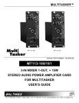
MULTI-TASKER
MANUAL PART NUMBER: 400-0209-001
MT113-100/101
3-IN MIXER 1-OUT, + 15W
STEREO AUDIO POWER AMPLIFIER CARD
FOR MULTI-TASKER.
USER’S GUIDE
MULTI-TASKER
TABLE OF CONTENTS
Page
PRECAUTIONS / SAFETY WARNINGS ...............2
GENERAL ..........................................................2
INSTALLATION..................................................2
CLEANING.........................................................2
FCC / CE NOTICE..............................................2
ABOUT YOUR MT113-100/101.............................3
TECHNICAL SPECIFICATIONS............................3
DESCRIPTION OF MT113-100/101 ......................4
APPLICATION DIAGRAM .....................................4
APPLICATION 1.................................................4
APPLICATION 2.................................................5
INSTALLING YOUR MT113-100/101 ....................8
OPERATION .........................................................8
RS-232 CONTROL.............................................8
RS-232 INTERFACE ..........................................8
DESCRIPTION OF COMMANDS .......................8
SUMMARY OF COMMANDS ...........................12
TROUBLESHOOTING GUIDE ............................12
ALTINEX POLICY ...............................................18
LIMITED WARRANTY......................................18
RETURN POLICY ............................................18
CONTACT INFORMATION ..............................18
1
1
MULTI-TASKER
PRECAUTIONS / SAFETY WARNINGS
•
1
Please read this manual carefully before using your
MT113-100/101. Keep this manual handy for future
reference. These safety instructions are to ensure
the long life of your MT113-100/101 and to prevent
fire and shock hazard. Please read them carefully
and heed all warnings.
1.1 GENERAL
•
•
•
•
•
•
Qualified ALTINEX service personnel, or their
authorized representatives must perform all
service.
To prevent fire or shock, do not expose this
unit to rain or moisture. Do not place the
MT113-100/101 in direct sunlight, near heaters
or heat radiating appliances, or near any
liquid. Exposure to direct sunlight, smoke, or
steam can harm internal components.
Handle the MT113-100/101 carefully. Dropping
or jarring can damage the card.
Do not pull the cables that are attached to the
MT113-100/101.
Insert the card carefully into the slots of the
Multi-Tasker™ without bending any edges.
When removing a card, pull it halfway through
to avoid damage to internal cables. If an
expansion card is being removed, please
make sure that the Main card to which it is
attached is also pulled out simultaneously.
•
1.3 CLEANING
•
Clean only the connector area with a dry cloth.
Never use strong detergents or solvents, such
as alcohol or thinner. Do not use a wet cloth or
water to clean the card. Do not clean or touch
any component or PCB.
1.4 FCC / CE NOTICE
•
This device complies with part 15 of the FCC
Rules. Operation is subject to the following two
conditions: (1) This device may not cause
harmful interference, and (2) this device must
accept any interference received, including
interference that may cause undesired
operation.
2
2
This equipment has been tested and found to
comply with the limits for a Class A digital
device, pursuant to Part 15 of the FCC Rules.
These limits are designed to provide
reasonable
protection
against
harmful
interference when the equipment is operated
in a commercial environment. This equipment
generates, uses, and can radiate radio
frequency energy and, if not installed and used
in accordance with the instruction manual, may
cause
harmful
interference
to
radio
communications. Operation of this equipment
in a residential area is likely to cause harmful
interference in which case the user will be
required to correct the interference at his own
expense.
Any changes or modifications to the unit not
expressly approved by ALTINEX, Inc. could
void the user’s authority to operate the
equipment.
MULTI-TASKER
ABOUT YOUR MT113-100/101
2
TECHNICAL SPECIFICATIONS
MT113-100/101
3 in Mixer, 1 fixed line level output
and 30W amplifier Card
FEATURES/DESCRIPTION
GENERAL
Inputs
Input Connectors
The MT113-100/101 is a Stereo Audio Power
Amplifier Card designed for use with the
MultiTasker™. When installed in the Basic
Enclosure (MT100-100), This card allows
connection of up to two line level balanced/
unbalanced inputs and 1 microphone. The Card
has a built in dual 15W power amplifier. The
MT113-100 has 70 Volt output for Sound
reinforcement speakers and MT113-101 has
Stereo Output to drive 8 Ohms speakers direct.
Input 1
Input 2
Input 3
3
MT113-100/101
(3) Terminal Blocks
Balanced/Unbalanced
Microphone Input
Line level
Balanced/Unbalanced
Line Level
Balanced/Unbalanced
Outputs
Fixed Output
Line Level
Balanced/Unbalanced
Speaker Output
MT113-100 70V
30Watts
Speaker Output
MT113-101 8 ohms
stereo 15 Wattas each
speaker output
Stereo
or Mono Audio
Compatibility
Table 1. MT113-100/101 General
Mixing is of input is selected via easy-to-use ASCII
commands from a control system or computer
connected to the RS-232 port of the MultiTasker™
Basic Enclosure. The MT113-100/101 can accept
balanced or unbalanced audio inputs and the
output can be wired for either balanced or
unbalanced audio output.
MECHANICAL
MT113-100/101
Basic Enclosure Slots
Three
Required
Weight
2.0 lb (0.45 kg)
Connector Panel
Black
T° Operating
10°C-50°C
T° Maximum
75°C
Humidity
90% non-condensing
MTBF (calc.)
55,000 hrs
Table 2. MT113-100/101 Mechanical
The MT113-100 is primarily designed to utilize the
70 Volt speaker system.
It has on board
Transformer to convert low impedance signal to
high voltage, high impedance output signal. This
card can supply tot al of 30 Watts of power to the
speakers.
The MT113-101 is primarily designed to utilize the
standard 8 Ohms stereo speaker systems. This
card can deliver full 15 Watts of power to each
speaker.
ELECTRICAL
Input Signals
Max Line Level Input
Max microphone Input
Power Amplifier
The MT113-100/101 has separate power supply
that is used to drive output of the power audio
amplifier. This power supply has universal power
input and can operat from 90 to 240 volts AC.
MT113-100/101
0 dBu (.7V p-p) 10k Ohms
-20dBu (70mv) 47 Kohm
Stereo 15 Watts per
channel
Mono 30 Watts 70V output
10 Hz to 20 kHz
Frequency Response
(+/- 0.5 dB)
Noise Floor
-97 dB @ 20 kHz
Table 3. MT113-100/101 Electrical
Through RS-232 control, the MT113-100/101 can
be controlled to adjust signal level of each input in
32 steps. In addition the volume, treble and bass of
the output amplifier can be adjusted in 32 steps.
Output Power
All three inputs to the amplifier are mixing inputs
and can be adjusted from 0db to –60db.
3
3
MULTI-TASKER
DESCRIPTION OF MT113-100/101
4
APPLICATION DIAGRAM
Application 1
4
4
5
MULTI-TASKER
Block Diagrams: Internal View of MT113-100/101
5
5
MULTI-TASKER
INSTALLING YOUR MT113-100/101
After processing a command, an OK or ER will be
returned as feedback if "F" is included at the end of
a command string or if the unit ID is zero.
6
Step 1. Slide the MT113-100/101 into an available
slot in the Multi-Tasker™ Basic Enclosure
in order to connect to the bus. Make sure
that the MT113-100/101 card fits into
place. Secure the card to the MultiTasker™ by tightening the retainer
screws located on the top and bottom of
the MT113-100/101 card.
7.2 DESCRIPTION OF COMMANDS
Each command consists of three parts: function,
card ID, and unit ID. [Function, Card ID, Unit ID]
Example:
[VERC3U2]
VER = Function
C3 = Card ID
U2 = Unit ID
For detailed information regarding function, see
each command description.
Step 2. The LED on the card panel will turn red
indicating that the card is in full operation.
A green LED indicates that a signal is
present. An LED that is blinking red
indicates that the card is experiencing a
problem. If the LED is blinking, see
Troubleshooting Guide in section 8.
Card ID is an assigned value from 1 to 19, which
represents the number of slots. Card ID 0 (C0) is
used for the controller (see user’s guide for the
MT100-100). Changing the position of a card will
significantly affect the commands recorded on
software definitions or a third party control system.
Step 3. Connect audio cables from the audio
source to the input connector of the
MT113-100/101. Connect the output
connectors of the MT113-100/101 to the
audio equipment through an audio cable.
Unit ID has a value from 0 to 9. Unit ID 0 should be
used for single unit operation. If the Unit ID is set to
0, then each command can be used without Ui (use
command [SETU0]; see user’s guide for the
MT100-100).
Step 4. Starting from the left, identify the slot
number where the MT113-100/101 card is
plugged into the Enclosure and note that
it is for RS-232 control.
Example:
OPERATION
7
[VERC3]: for unit ID zero
[VERC3Ui]: for unit ID other than zero
[VERC3]: equivalent to [VERC3U0]
7.1 RS-232 CONTROL
When used in the Multi-Tasker™ Enclosure, the
MT113-100/101 has many advanced remote control
capabilities, which are accessible through standard
RS-232 communication. The actual controlling can
be accomplished through a computer control system
or any other device capable of sending RS-232
commands.
1. [VERCnUi]
This command receives the software version
and card type for the MT113-100/101 card.
Cn = card ID number (n = # from 1 to 19)
Ui = Unit ID (i = # from 0 to 9) (refer to the
MT100-100 user’s guide for explanation)
7.1.1 RS-232 INTERFACE
Example:
The RS-232 commands for the MT113-100/101 are
in a simple ASCII character format.
1.
2.
3.
If one MT113-100/101 card is in slot #2 of
unit 3:
To send command [VERC2U3], the MultiTasker™ Enclosure will return:
Square brackets “[ ]” are part of the
command.
Use uppercase letters for all commands.
Commands may be executed with or
without a space.
[Ver A1 MT113-100_101 C02]
2. [CnUi]
8
8
MULTI-TASKER
This command receives the status of the card.
Command Format: [CnUi]
Cn = card id (n = 1 to 19)
Ui = unit id (i = from 0 to 9) (refer to the
MT100100 user’s guide for explanation)
Example:
If all of the inputs on the MT113-100/101
card are
OFF and the card is in slot #5 of unit 3:
1) [ON1C5U3]: Turns ON only input 1 of the
MT113-100/101 card.
2) [ON3C5U3]: Turns ON only input 3
Example:
If one MT113-100/101 card is in slot #2 of
unit 3
with input 1 ON:
To send command [C2U3], the MultiTasker™
Enclosure will return feedback as [On1 C02]
or
[On1 ER03 C02] if there is an error number 3
(see error code list).
If there is no card in slot #2 of unit 3, sending
the [C2U3] command will not return any
feedback.
4. [OFFmCnUi]
This command disables one or all inputs of a
single card or a group of cards.
[OFFmCnUi]: for a single card
This command disables input “m” or all inputs.
[OFFC5CnUi]: Turns OFF all inputs of the
MT113-100/101 card.
m = Input number (m = 1 to 8)
n = Card ID number (n = slot # from 1 to 19)
i = Unit ID number (i = 0 to 9)
Example:
If card 5 of unit 3 has input 1 ON, the
following
commands can be used to turn OFF the
input.
1) [OFF1C5U3]: Turns OFF only input 1.
ERROR CODES
ER01: CPU Error
This error indicates that the CPU is not
working
properly.
ER02: I²C Communication Error
This means that the communication between
the MT113-100/101 card and its serial device
has failed.
5. [SELmCnUi]
This command sets path to adjust the
individual volume level for single card.
Command Format: [SELmCnUi] [–] [–] [–] [–] or
[+] [+] [+] [+]
m = Input number (m = 1 to 3)
n = Card ID number (n = slot # from 1 to 19)
i = Unit ID number (i = 0 to 9)
+ = increases volume. (maximum of 15 levels
for audio).
– = decreases volume. (maximum of 15 levels
for audio).
ER03: RS485 Communication Error
This type of error is a communication error
between the MT113-100/101 card and the
controller of the Multi-Tasker™ Enclosure.
3.
[ONmCnUi]
This command enables one input of a single
card or a group of cards.
•
[ONmCnUi]: for a single card
This command enables input “m” and disables
all other inputs.
Example:
If the status of audio card 5 of unit zero is as
follows:
VOLIN1:16
VOLIN2:16
VOLIN3:32
VOLOUT:12
Default when plugged in = ALL OFF
m = Input number (m = 1 to 8)
n = Card ID No. (n = slot # from 1 to 19)
i = Unit ID number (i = 0 to 9)
9
9
MULTI-TASKER
BASS:8
TREBLE:14
LOUDNESS:ON
Send commands [SEL2C5] [+] [+] [+] [+] [+].
After executing that command, send [C5] to get
the new status of card 5:
VOLIN1:16
VOLIN2:21
VOLIN3:32
VOLOUT:12
BASS:8
TREBLE:14
LOUDNESS:ON
VOLIN1:16
VOLIN2:16
VOLIN3:32
VOLOUT:12
BASS:8
TREBLE:14
LOUDNESS:ON
Send commands [SEL2C5] [+] [+] [+] [+] [+].
After executing that command, send [C5] to get
the new status of card 5:
VOLIN1:16
VOLIN2:21
VOLIN3:32
VOLOUT:12
BASS:8
TREBLE:14
LOUDNESS:ON
[SELmGkUi]
This command sets path to adjust the individual
volume level for a group of cards. Command
Format: [SELmGkUi] [–] [–] [–] [–] or [+] [+] [+]
[+]
m = Input number (m = 1 to 3)
k = group number (k = # from 1-9)
i = Unit ID number (i = 0 to 9)
+ = increases volume. (maximum of 15 levels
for audio).
– = decreases volume. (maximum of 15 levels
for audio).
Example:
If card 1, 2, and 3 are grouped as group 5 of
unit 1, send the [SEL1G5U1] [–] [–] [–]
command to decrease the volume for card 1, 2,
and 3 simultaneously.
• [SELmGkUi]
This command sets path to adjust the individual
volume level for a group of cards. Command
Format: [SELmGkUi] [–] [–] [–] [–] or [+] [+] [+]
[+]
m = Input number (m = 1 to 3)
k = group number (k = # from 1-9)
i = Unit ID number (i = 0 to 9)
+ = increases volume. (maximum of 15 levels
for audio).
– = decreases volume. (maximum of 15 levels
for audio).
Example:
If card 1, 2, and 3 are grouped as group 5 of unit 1,
send the [SEL1G5U1] [–] [–] [–] command to
decrease the volume for card 1, 2, and 3
simultaneously.
6. [SELmCnUi]
This command sets path to adjust the individual
volume level for single card. Command Format:
[SELmCnUi] [–] [–] [–] [–] or [+] [+] [+] [+]
m = Input number (m = 1 to 3)
n = Card ID number (n = slot # from 1 to 19)
i = Unit ID number (i = 0 to 9)
+ = increases volume. (maximum of 15 levels
for audio).
– = decreases volume. (maximum of 15 levels
for audio).
7. SLOCnUi]
This command sets path to adjust the output
volume level for single card. Command Format:
[SLOCnUi] [–] [–] [–] [–] or [+] [+] [+] [+]
n = Card ID number (n = slot # from 1 to 19)
i = Unit ID number (i = 0 to 9)
+ = increases volume. (maximum of 15 levels
for audio).
– = decreases volume. (maximum of 15 levels
for audio).
Example:
Example:
If the status of audio card 5 of unit zero is as
follows:
10
10
MULTI-TASKER
If the status of audio card 5 of unit zero is as
follows:
VOLIN1:16
VOLIN2:21
VOLIN3:32
VOLOUT:12
BASS:8
TREBLE:14
LOUDNESS:ON
Send commands [SLOC5] [+] [+] [+] [+] [+].
After executing that command, send [C5] to get
the new status of card 5:
VOLIN1:16
VOLIN2:21
VOLIN3:32
VOLOUT:17
BASS:8
TREBLE:14
LOUDNESS:ON
VOLIN1:16
VOLIN2:21
VOLIN3:32
VOLOUT:17
BASS:8
TREBLE:14
LOUDNESS:ON
Send commands [VL1A2CnUi], [VL2A12CnUi],
[VL3A18CnUi]. After executing the above
commands, send [C2] to get the new status of
card 2:
VOLIN1:2
VOLIN2:12
VOLIN3:18
VOLOUT:17
BASS:8
TREBLE:14
LOUDNESS:ON
• [VLmAyGkUi]
This command sets absolute individual volume
level for a group of cards. Command Format:
[VLmAyGkUi]
m = Input number (m = 1 to 3)
y = Absolute audio level (y = 1 to 15)
k = group number (k = # from 1-9)
i = Unit ID number (i = 0 to 9)
Example:
If card 1, 2, and 3 are grouped as group 5 of
unit 1, send the [VL2A32G5U1] command to set
maximum volume for card 1, 2, and 3
simultaneously.
• [SELmGkUi]
This command sets path to adjust the individual
volume level for a group of cards. Command
Format: [SLOGkUi] [–] [–] [–] [–] or [+] [+] [+] [+]
k = group number (k = # from 1-9)
i = Unit ID number (i = 0 to 9)
+ = increases volume. (maximum of 15 levels
for audio).
– = decreases volume. (maximum of 15 levels
for audio).
Example:
If card 1, 2, and 3 are grouped as group 5 of
unit 1, send the [SEL1G5U1] [–] [–] [–]
command to decrease the volume for card 1, 2,
and 3 simultaneously.
9. [VLOAyCnUi]
This command sets absolute individual volume
level for single card. Command Format:
[VLOAyCnUi]
y = Absolute audio level (y = 1 to 32)
n = Card ID number (n = slot # from 1 to 19)
i = Unit ID number (i = 0 to 9)
Example:
If the status of audio card 2 of unit zero is as
follows:
VOLIN1:16
VOLIN2:21
VOLIN3:32
VOLOUT:17
BASS:8
TREBLE:14
8. VLmAyCnUi]
This command sets absolute individual volume
level for single card. Command Format:
[VLmAyCnUi]
m = Input number (m = 1 to 3)
y = Absolute audio level (y = 1 to 32)
n = Card ID number (n = slot # from 1 to 19)
i = Unit ID number (i = 0 to 9)
Example:
If the status of audio card 2 of unit zero is as
follows:
11
11
MULTI-TASKER
LOUDNESS:ON
Send commands [VLOA8CnUi]. After executing
this command, send [C2] to get the new status
of card 2:
VOLIN1:2
VOLIN2:12
VOLIN3:18
VOLOUT:8
BASS:8
TREBLE:14
LOUDNESS:ON
• [VLmAYGkUi]
This command sets absolute individual volume
level for a group of cards. Command Format:
[VLOAyGkUi]
y = Absolute audio level (y = 1 to 15)
k = group number (k = # from 1-9)
i = Unit ID number (i = 0 to 9)
Example:
If card 1, 2, and 3 are grouped as group 5 of
unit 1, send the [VLOA32G5U1] command to
set maximum volume for card 1, 2, and 3
simultaneously.
VOLIN2:12
VOLIN3:18
VOLOUT:8
BASS:13
TREBLE:14
LOUDNESS:ON
• [SEBGkUi]
This command sets path to adjust the bass level
for a group of cards. Command Format:
[SEBGkUi] [–] [–] [–] [–] or [+] [+] [+] [+]
k = group number (k = # from 1-9)
i = Unit ID number (i = 0 to 9)
+ = increases volume. (maximum of 15 levels
for bass).
– = decreases volume. (maximum of 15 levels
for bass).
Example:
If card 1, 2, and 3 are grouped as group 5 of
unit 1, send the [SEB1G5U1] [–] [–] [–]
command to decrease the volume for card 1, 2,
and 3 simultaneously.
11. [VBLyCnUi]
This command sets absolute bass level for
single card. Command Format: [VBLyCnUi]
y = Absolute bass level (y = 1 to 15)
n = Card ID number (n = slot # from 1 to 19)
i = Unit ID number (i = 0 to 9)
Example:
If the status of audio card 2 of unit zero is as
follows:
VOLIN1:2
VOLIN2:12
VOLIN3:18
VOLOUT:8
BASS:8
TREBLE:14
LOUDNESS:ON
After sending a command [VBL2CnUi] on
request [C2] we will the new status of card 2:
VOLIN1:2
VOLIN2:12
VOLIN3:18
VOLOUT:8
BASS:2
TREBLE:14
LOUDNESS:ON
10. [SEBCnUi]
This command sets path to adjust the bass level
for single card. Command Format: [SEBCnUi] [–
] [–] [–] [–] or [+] [+] [+] [+]
n = Card ID number (n = slot # from 1 to 19)
i = Unit ID number (i = 0 to 9)
+ = increases volume. (maximum of 15 levels
for bass).
– = decreases volume. (maximum of 15 levels
for bass).
Example:
If the status of audio card 5 of unit zero is as
follows:
VOLIN1:2
VOLIN2:12
VOLIN3:18
VOLOUT:8
BASS:8
TREBLE:14
LOUDNESS:ON
Send commands [SEBC5] [+] [+] [+] [+] [+].
After executing that command, send [C5] to get
the new status of card 5:
VOLIN1:2
12
12
MULTI-TASKER
This command sets path to adjust the bass level
for a group of cards. Command Format:
[STBGkUi] [–] [–] [–] [–] or [+] [+] [+] [+]
k = group number (k = # from 1-9)
i = Unit ID number (i = 0 to 9)
+ = increases volume. (maximum of 15 levels
for treble).
– = decreases volume. (maximum of 15 levels
for treble).
Example:
If card 1, 2, and 3 are grouped as group 5 of
unit 1, send the [STB1G5U1] [–] [–] [–]
command to decrease the treble volume for
card 1, 2, and 3 simultaneously.
• [VBLyGkUi]
This command sets absolute bass level for a
group of cards. Command Format: [VBLyGkUi]
y = Absolute bass level (y = 1 to 15)
k = group number (k = # from 1-9)
i = Unit ID number (i = 0 to 9)
Example:
If card 1, 2, and 3 are grouped as group 5 of
unit 1, send the [VBLFG5U1] command to set
maximum volume of bass for card 1, 2, and 3
simultaneously.
12. [STBCnUi]
This command sets path to adjust the treble
level for single card. Command Format:
[STBCnUi] [–] [–] [–] [–] or [+] [+] [+] [+]
n = Card ID number (n = slot # from 1 to 19)
i = Unit ID number (i = 0 to 9)
+ = increases volume. (maximum of 15 levels
for treble).
– = decreases volume. (maximum of 15 levels
for treble).
Example:
If the status of audio card 5 of unit zero is as
follows:
VOLIN1:2
VOLIN2:12
VOLIN3:18
VOLOUT:8
BASS:8
TREBLE:14
LOUDNESS:ON
13. [VTLyCnUi]
This command sets absolute treble level for
single card. Command Format: [VTLyCnUi]
y = Absolute treble level (y = 1 to 15)
n = Card ID number (n = slot # from 1 to 19)
i = Unit ID number (i = 0 to 9)
Example:
If the status of audio card 2 of unit zero is as
follows:
VOLIN1:2
VOLIN2:12
VOLIN3:18
VOLOUT:8
BASS:8
TREBLE:14
LOUDNESS:ON
After sending a command [VTL2CnUi] on
request [C2] we will the new status of card 2:
VOLIN1:2
VOLIN2:12
VOLIN3:18
VOLOUT:8
BASS:8
TREBLE:2
LOUDNESS:ON
Send commands [STBC5] [-] [-] [-] [-]. After
executing that command, send [C5] to get the
new status of card 5: [On123C5]
VOLIN1:2
VOLIN2:12
VOLIN3:18
VOLOUT:8
BASS:8
TREBLE:10
LOUDNESS:ON
• [VTLYGkUi]
This command sets absolute treble level for a
group of cards. Command Format: [VTLYGkUi]
Y = Absolute treble level (Y = 0 to F in hex
format)
k = group number (k = # from 1-9)
• [STBGkUi]
13
13
MULTI-TASKER
i = Unit ID number (i = 0 to 9)
Example:
If card 1, 2, and 3 are grouped as group 5 of
unit 1, send the [VTLFG5U1] command to set
maximum volume of treble for card 1, 2, and 3
simultaneously.
m = Input number (m = 1 to 3)
n = card ID No. (n = slot # from 1 to 19)
i = unit number (i = # from 0-9)
Example:
To save setting for audio input 1 for card in slot
8 send command [SIV1C8U1].
13. [LOD0CnUi]
This command turns OFF loudness feature for
single card.
n = Card ID number (n = slot # from 1 to 19)
i = Unit ID number (i = 0 to 9)
17. [SOVCnUi]
This command saves audio output level. So on
the next power up this settings will be activated.
Command Format:
n = card ID No. (n = slot # from 1 to 19)
i = unit number (i = # from 0-9)
Example:
To save setting for audio output on card in slot 8
send command [SOVC8U1].
• [LOD1CnUi]
This command turns ON loudness feature for
group of cards simultaneously.
n = Card ID number (n = slot # from 1 to 19)
i = Unit ID number (i = 0 to 9)
18. [SBVCnUi
This command saves audio bass level. So on
the next power up this settings will be activated.
Command Format:
n = card ID No. (n = slot # from 1 to 19)
i = unit number (i = # from 0-9)
Example:
To save setting for audio bass level on card in
slot 2 send command [SBVC2U1].
• [LOD1GkUi]
This command turns ON loudness feature for
single card.
k = group number (k = # from 1-9)
i = Unit ID number (i = 0 to 9)
• [LOD0GkUi]
This command turns OFF loudness feature for
group of cards simultaneously.
k = group number (k = # from 1-9)
i = Unit ID number (i = 0 to 9)
19. [STVCnUi]
This command saves audio treble level. So on
the next power up this settings will be activated.
Command Format:
n = card ID No. (n = slot # from 1 to 19)
i = unit number (i = # from 0-9)
Example:
To save setting for audio treble level on card in
slot 4 send command [STVC4U1].
14. [MUT0CnUi]
This command turns ON speaker output.
n = Card ID number (n = slot # from 1 to 19)
i = Unit ID number (i = 0 to 9)
15. [MUT1CnUi]
This command turns OFF speaker output.
n = Card ID number (n = slot # from 1 to 19)
i = Unit ID number (i = 0 to 9)
20. [SLVCnUi]
This command saves state of loudness function.
So on the next power up this settings will be
activated. Command Format:
n = card ID No. (n = slot # from 1 to 19)
i = unit number (i = # from 0-9)
Example:
16. [SIVmCnUi]
This command saves audio input level. So on the
next power up this settings will be activated.
Command Format:
14
14
MULTI-TASKER
To save setting loudness on card in slot 10 send
command [SLVC10U1].
This command reads card memory at address
XX . Command Format: [RDXXCnUi]
XX = data address (XX = # from 60-FF in hex
format)
n = card ID No. (n = slot # from 1 to 19)
i = unit number (i = # from 0-9)
Example:
To read memory at address 0x0A card 2 of unit
1, send the [RD0AC2U1] command. The system
will return feedback as RD0A1DC2, if data at
address 0x0A is 0x1D.
21. [WR….GkUi]
This command groups multiple cards in the
MT100-100 Enclosure. Each unit contains a
maximum of nine groups. Command Format:
[WRCn…GkUi]
n = card ID No. (n = slot # from 1 to 19)
k = group number (k = # from 1-9)
i = unit number (i = # from 0-9)
Example:
To group card #1, 2, and 3 as group 5 of unit
#1, send the [WRC1C2C3G5U1] command.
After executing this command, cards 1, 2, and 3
of unit 1 will be grouped together as group 5.
25. [WRXXYY]
This command writes data YY into card memory
at address XX . Command Format:
[RDXXYYCnUi]
XX = data address (XX = # from 60-FF in hex
format)
YY = data (YY = # from 00-FF in hex format)
n = card ID No. (n = slot # from 1 to 19)
i = unit number (i = # from 0-9)
Example:
To write data 0x2B into memory at address
0x10 card 5 of unit 1, send the [RD102BC5U1]
command. The system will return feedback as
OK.
22. [CLR]
This command clears the members for a single
group or for all nine groups. Command Format:
[CLRGkUi]
k = group number (k = # from 1-9)
i = unit number (i = # from 0-9)
Example:
a) To clear group #1, send the [CLRG1U1]
command. This command clears the members
for the specified group only.
b) b) To clear all groups of unit 1, send the [CLR
G....U1] command.
26. [WRCn…GkUi]
This command groups multiple cards in the
MT100-100 Enclosure. Each unit contains a
maximum of nine groups.
n = card ID No. (n = slot # from 1 to 19)
k = group number (k = # from 1-9)
i = unit number (i = # from 0-9)
23. [GkUi]
This command is used to request group data.
With the command, the user can identify which
input or output of a particular group is on.
Command Format: [GkUi]
k = group number (k = # from 1-9)
i = unit number (i = # from 0-9)
Example:
If group 1 has DA Cards with output 1 and 2 on,
while group 2 has SW Cards with input 2 on:
1) [G1]: will return feedback as [On12G1].
2) [G2]: will return feedback as [On2G2].
Example:
To group card #1, 2, and 3 as group 5 of unit
#1, send the [WRC1C2C3G5U1] command.
After executing this command, cards 1, 2, and
3 of unit 1 will be grouped together as group 5.
27. [CLRGkUi]
This command clears the members for a single
group or for all nine groups.
Command Format: [CLRGkUi]
k = group number (k = # from 1-9)
i = unit number (i = # from 0-9)
24. [RDXX]
15
15
MULTI-TASKER
the slot used is good by seeing
if the other card’s LED lights
in that slot. If it lights, then the
original card may be the source
of the problem. Call ALTINEX at
(714) 990-2300.
Example:
a) To clear group #1, send the [CLRG1U1]
command. This command clears the
members
for the specified group only.
b) To clear all groups of unit 1, send the
[CLR G✻U1] command.
.
TROUBLESHOOTING GUIDE
8.2 LED IS BLINKING RED
If the LED on the card is blinking red, find the error
code. For example, if you are using card 5 of unit
1, send the [C5U1] command to see the status and
error code. Note that card 5 refers to slot 5.
8
We have carefully tested and have found no
problems in the supplied MT113-100/101; however,
we would like to offer suggestions for the following:
•
•
•
•
•
A) Cause 1:
8.1 LED IS NOT LIT
8.2 LED IS BLINKING RED
8.3 NO SOUND
8.4 SOUND DISTORTION
8.5 SOUND LEVEL IS LOW
- If the CPU is not working, you
will receive an ER01 message.
The system will return feedback
as [On1 ER01 C05] when
using card 5 of unit 1.
8.1 LED IS NOT LIT
A) Cause 1:
Card cage is not plugged in.
Solution:
Plug card cage in. If the LED
lights, the problem is solved. If
the LED is still not lit, see
Cause 2.
- ER01 Code: CPU error
Solution 1:
Look at the card and verify that
there is no damage. If there is
no damage, see Solution 2.
Solution 2: Verify that all IC’s are seated in
their sockets. If the LED is still
blinking red, see Solution 3.
B) Cause 2: Card is not plugged in all the
way.
Solution: Push the card in all the way. If
the LED is still not lit, see
Cause 3.
C) Cause 3:
The CPU on the card is not
working properly.
Solution 3: Call ALTINEX at (714) 990-2300.
B) Cause 2:
Card cage slot has a problem.
Solution 1: Test the card in other slots of
the card cage. If the slot was
damaged, the card may work in
other slots. If other slots work
and the LED lights, the problem
is the card cage slot. The card
cage may require service. Call
ALTINEX at (714) 990-2300. If
the other slots do not work and
the LED is still not lit, see
Solution 2.
The MT113-100/101 card and its
serial device are not
communicating.
- If there is no communication
between the MT113-100/101
card
and its serial device, you
will receive an ER02 message.
The system will return
feedback as [On1 ER02 C05]
when using card 5 of unit 1.
- ER02 Code: Communication
error between the MT113100/101
Solution 2: Take any other known good
card with an LED and verify that
card and its serial device.
16
16
MULTI-TASKER
Solution 1: Turn the system OFF and then
ON again. If there is still an error
message, see Solution 3.
wiring are good. If there is still no
sound present, see Cause 4.
D) Cause 4:
Solution 2: Call ALTINEX at (714) 990-2300.
C) Cause 3:
RS485 communication error
Solution 1: Make sure that the destination
amplifier is powered. If there is
still no sound, see Solution 2
- If there is an RS485
communication error, you will
receive an ER03 message. The
system will return feedback as
[On1 ER03 C05] when using
card 5 of unit 1.
Solution 2: Set the volume of the destination
amplifier to a reasonable level. If
there is still no sound, call
ALTINEX at (714) 990-2300.
8.4 SOUND DISTORTION
- ER03 Code: RS485
communication error
Solution 1:
A) Cause 1:
Make sure that the card is
pushed all the way into the slot.
If there is still an ER03
message, see Solution 2.
Solution 2: Turn the system OFF and then
ON again. If there is still an error
message, see Solution 3.
Solution1:
Make sure that the source level is
below 1V p-p. If the sound is still
distorted, see Cause 2.
Solution 2:
Call ALTINEX at (714) 990-2300.
A) Cause 1: The volume levels are
inappropriate.
8.3 NO SOUND
Solution 1:
Turn up the source volume. If
sound level is still low, see
Solution 2.
Solution 2:
Turn up the destination amplifier
volume. If the sound level is still
low, see Cause 2.
A) Cause 1: The source has a problem.
B) Cause 2:
Solution:
C) Cause 3:
Solution:
The source level is above 1V
p-p.
8.5 SOUND LEVEL IS LOW
Solution 3: If there is still a problem, call
ALTINEX at (714) 990-2300.
Solution:
The destination amplifier has a
problem.
Check the source and make sure
that it is working at an
appropriate volume level and all
source connections are correct. If
the source is working and there
is still no sound, see Cause 2.
B) Cause 2: Poor signal transmission.
Solution:
The proper card input may not
be selected.
Select the card input that is
used, by RS-232 accessible
commands in section 7. If no
sound is present, see Cause 3.
Check the cables for continuity
and make sure that connections
are wired properly to verify that
there is good signal transmission.
Note: Test the system by removing the card from
between the source and the destination amplifier. If
problem persists, call ALTINEX at (714) 990-2300.
Cable connections to the
destination are incorrect.
Make sure that cables are
connected properly. Also, make
sure that the continuity and
17
17
MULTI-TASKER
ALTINEX POLICY
If your product is out of warranty and needs service,
contact the ALTINEX Sales Department for an RMA
(Return Material Authorization). Products returned
without an RMA number may experience a delay in
service. The service charges will be quoted to you
before the actual repairs are done.
9
9.1 LIMITED WARRANTY
ALTINEX warrants that its products and cables are
free from defects in materials under normal use and
service. This warranty is limited to repairing at
company’s factory any part or parts of the product,
which upon company’s examination shall disclose to
be, thus defective. Products considered defective
should be returned to company with transportation
charges pre-paid within 2 years (90 days for cables)
from date of shipment to the purchaser. The
warranty is expressly instead of all other warranties
expressed or implied. ALTINEX neither assumes
nor authorizes any other person to assume for it any
other liability in connection with the sale of the
products. This warranty shall not apply to any
product that shall have been repaired or altered
outside of company’s factory in any way so as, in its
judgment, to affect its stability or reliability, or that
has been subject to misuse, negligence or accident.
9.3 CONTACT INFORMATION
ALTINEX, INC.
592 Apollo Street
Brea, CA 92821 USA
TEL: 714-990-2300
TOLL FREE: 1-800-ALTINEX
WEB: www.altinex.com
E-MAIL: [email protected]
FAX: 714-990-3303
9.2 RETURN POLICY
It is very important to ALTINEX that you receive the
products that you have ordered and that this product
fulfills your need. In the unlikely event, that an
ALTINEX product needs to be returned please
follow the policies below:
ALTINEX will accept product returns for a period of
30 days from authorized ALTINEX dealers.
Products must be returned in an unopened
package.
If a product has been opened, the restocking fees
will apply. For the restocking fee amount, please
contact an ALTINEX Sales Representative.
If the product is in your possession for more than 30
days, the restocking fees will apply.
ALTINEX will not accept any returns on cables or
custom products.
If your product is in warranty and needs service,
contact the ALTINEX Sales Department for an RMA
(Return Material Authorization). Products returned
without an RMA number may experience a delay in
service.
18
18