1
MULTI-TASKER™
MANUAL PART NUMBER: 400-0343-003
MT109-102
3 IN 1 OUT AUDIO/MIC MIXER
FOR MULTI-TASKER™
USER’S GUIDE
MULTI-TASKER™
TABLE OF CONTENTS
Page
PRECAUTIONS / SAFETY WARNINGS .............. 2
GENERAL..........................................................2
CLEANING.........................................................2
FCC / CE NOTICE..............................................2
ABOUT YOUR MT109-102 .................................. 3
TECHNICAL SPECIFICATIONS .......................... 3
DESCRIPTION OF MT109-102 ............................ 4
APPLICATION DIAGRAM .................................... 5
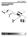
DIAGRAM 1: TYPICAL SETUP ..........................5
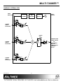
DIAGRAM 2: INTERNAL VIEW ..........................6
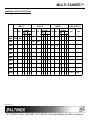
DIAGRAM 3: SWITCH POSITIONS ...................7
INSTALLING YOUR MT109-102 .......................... 8
OPERATION ........................................................ 8
RS-232 CONTROL ............................................8
DESCRIPTION OF COMMANDS .......................8
SUMMARY OF COMMANDS ...........................19
MENU MODE ...................................................20
TROUBLESHOOTING GUIDE ........................... 24
LED IS NOT ON ...............................................24
NO SOUND......................................................24
SOUND DISTORTION .....................................25
SOUND LEVEL IS LOW...................................25
ALTINEX POLICY .............................................. 25
LIMITED WARRANTY/RETURN POLICY ........25
CONTACT INFORMATION ..............................25
400-0343-003
1
1
MULTI-TASKER™
PRECAUTIONS / SAFETY WARNINGS ....... 1
•
This equipment has been tested and found to
comply with the limits for a Class A digital
device, pursuant to Part 15 of the FCC Rules.
These limits are designed to provide reasonable
protection against harmful interference when
the equipment is operated in a commercial
environment. This equipment generates, uses,
and can radiate radio frequency energy and, if
not installed and used in accordance with the
instruction manual, may cause harmful
interference to radio communications. Operation
of this equipment in a residential area is likely to
cause harmful interference in which case the
user will be required to correct the interference
at their expense.
•
Any changes or modifications to the unit not
expressly approved by ALTINEX, Inc. could void
the user’s authority to operate the equipment.
Please read this manual carefully before using
your MT109-102. Keep this manual handy for
future reference. These safety instructions are to
ensure the long life of your MT109-102 and to
prevent fire and shock hazard. Please read them
carefully and heed all warnings.
1.1 GENERAL
•
Qualified ALTINEX service personnel, or their
authorized representatives, must perform all
service.
•
To prevent fire or shock, do not expose this unit
to rain or moisture. Do not place the MT109-102
in direct sunlight, near heaters or heat radiating
appliances, or near any liquid. Exposure to
direct sunlight, smoke, or steam can harm
internal components.
•
Handle the MT109-102 carefully. Dropping or
jarring can damage the card.
•
Do not pull the cables that are attached to the
MT109-102.
•
Insert the card carefully into the slots of the
Multi-Tasker™ without bending any edges.
1.2 CLEANING
•
Clean only the connector area with a dry
cloth. Never use strong detergents or solvents,
such as alcohol or thinner. Do not use a wet
cloth or water to clean the card. Do not clean or
touch any component or PCB.
1.3 FCC / CE NOTICE
•
This device complies with part 15 of the FCC
Rules. Operation is subject to the following two
conditions: (1) This device may not cause
harmful interference, and (2) this device must
accept any interference received, including
interference that may cause undesired
operation.
400-0343-003
2
2
MULTI-TASKER™
ABOUT YOUR MT109-102
2
TECHNICAL SPECIFICATIONS
MT109-102
3 in 1 out Audio Mixer Card
FEATURES/DESCRIPTION
GENERAL
Inputs
Input Connectors
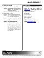
The MT109-102 is a Stereo Audio Mixer Card.
When installed in the Basic Enclosure
(MT100-100), this card allows connection of up to
three line level balanced or unbalanced
microphone inputs.
MT109-102
(3) Terminal Blocks
Balanced/Unbalanced
Microphone Input
Balanced/Unbalanced
Microphone Input
Balanced/Unbalanced
Microphone Input
Input 1
Input 2
Input 3
Mixing of inputs is controled via easy-to-use ASCII
commands from a control system or computer
connected to the RS-232 port of the MultiTasker™
Basic Enclosure. The MT109-102 can accept
balanced or unbalanced audio inputs and the
output can be wired for either balanced or
unbalanced audio output.
Outputs
Output Connector
(1) Terminal Block
Output
Line Level
Balanced/Unbalanced
Stereo or Mono Audio
Compatibility
Through RS-232 control, the MT109-102 can be
controlled to adjust the signal level of each input in
16 steps. In addition the volume, treble and bass
of the output amplifier can be adjusted in 16 steps.
3
Table 1. MT109-102 General
MECHANICAL
Basic Enclosure Slots
Required
Weight
Connector Panel
T° Operating
T° Maximum
Humidity
MTBF (calc.)
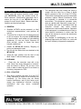
All three inputs to the amplifier are mixing inputs
and can be adjusted from 0db to –60db.
Phantom Power +12V can be connected to the
microphone input using a dip-switch located on the
PCB.
MT109-102
One Slot
0.43 lb (0.19 kg)
Black
10°C-50°C
75°C
90% non-condensing
55,000 hrs
Table 2. MT109-102 Mechanical
ELECTRICAL
Input Signals
Max Line Level Input
Max microphone Input
Frequency Response
Noise Floor
MT109-102
0 dBu (.7V p-p) 10k Ohms
-65dBu (2-10mv) 47 Kohm
10 Hz to 20 kHz
(+/- 0.5 dB)
-97 dB @ 20 kHz
Table 3. MT109-102 Electrical
400-0343-003
3
3
MULTI-TASKER™
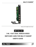
DESCRIPTION OF MT109-102
400-0343-003
4
4
4
MULTI-TASKER™
APPLICATION DIAGRAM
5
DIAGRAM 1: TYPICAL SETUP
400-0343-003
5
5
MULTI-TASKER™
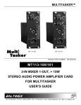
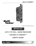
DIAGRAM 2: INTERNAL VIEW
AUDIO
INPUTS TB
PHANTOM
POWER
MP
CONTROL
AUDIO
OUTPUT
POWER
SUPPLY
SW5
M+
SW4
M-
MIC
LINE/MIC
INPUT1
BALANCED
SW1
S/W
GAIN
VOLUME
BASS
TREBLE
SW7
M+
SW6
M-
MIC
SW2
LINE/MIC
INPUT2
BALANCED
S/W
GAIN
Σ
SW9
M+
SW8
M-
MIC
LINE/MIC
INPUT3
BALANCED
400-0343-003
SW3
S/W
GAIN
6
6
SW10
S/W
GAIN
FIXED MIX LINE
LEVEL OUTPUT
OR
ADJUSTABLE
MIX LINE
LEVEL OUTPUT
TERMINAL
BLOCK
MULTI-TASKER™
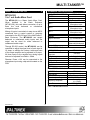
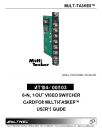
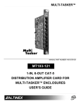
DIAGRAM 3: SWITCH POSITIONS
INPUT1
INPUT2
PHANTOM
POWER
LINE MIC
ON
OFF
INPUT3
PHANTOM
POWER
LINE MIC
- + - +
OFF
ON
LINE OUTPUT
PHANTOM
POWER
LINE MIC
- + - +
ON
OFF
FIX
ADJ
- + - +
SW1 OFF ON
SW2
OFF ON
SW3
SW4
SW5
SW6
SW7
OFF ON
ON
OFF
ON
OFF
ON
OFF
ON
SW8
ON
SW9
OFF
ON
OFF
OFF
SW10
400-0343-003
OFF
7
7
ON
MULTI-TASKER™
INSTALLING YOUR MT109-102
6
OPERATION
Step 1. Turn off the power to the Multi-Tasker™
enclosure.
7
7.1 RS-232 CONTROL
When used in the Multi-Tasker™ Enclosure, the
MT109-102 has many advanced remote control
capabilities, which are accessible through standard
RS-232 communication. The actual controlling can
be accomplished through a computer control
system or any other device capable of sending
RS-232 commands.
Step 2. Slide the MT109-102 into an available
slot in the Multi-Tasker™ Basic Enclosure
in order to connect to the bus. Make sure
that the MT109-102 card fits into place.
Step 3. Secure the card to the Multi-Tasker™ by
tightening the retainer screws located on
the top and bottom of the MT109-102
card.
7.1.1 RS-232 INTERFACE
The RS-232 commands, for the MT109-102 are
in a simple ASCII character format.
Step 4. Turn the Multi-Tasker™ system power
back on.
Step 5. The LED on the card panel will turn red
indicating that the card is in full operation.
Step 6. Connect audio cables from the audio
source to the input connector of the
MT109-102.
Connect
the
output
connectors of the MT109-102 to the
audio equipment through an audio cable.
1.
Square brackets “[
command.
]” are part of the
2.
Use uppercase letters for all commands.
After processing a command, an OK or ER will
be returned as feedback if "F" is included at the
end of a command string.
Commands ending in "S" will be saved into
memory. Commands not ending in "S" will still
be executed but will not be restored when the
system is reset or powered OFF then ON.
Step 7. Starting from the left, identify the slot
number where the MT109-102 card is
plugged into the Enclosure and note that
it is for RS-232 control.
7.2 DESCRIPTION OF COMMANDS
Each command consists of three
Function, Card ID, and Unit ID.
[ Function , Card ID , Unit ID ]
parts:
Example: [VERC3U2]
VER = Function
C3 = Card ID or Group ID
U2 = Unit ID
For Function, see a detailed explanation under
each command description.
The Card ID is an assigned value. It is equal to
the enclosure slot number in which the card is
installed. The value can range from 1 to 4 up to
1 to 20 depending on the enclosure.
Card ID 0 (C0) is used for the controller. See
the MT100-100 User’s Guide for details.
400-0343-003
8
8
MULTI-TASKER™
The Group ID is a number representing a group
of cards defined with the [WR] command.
When using the Group ID, all cards in the group
will perform the given instruction.
Example:
There is one MT109-102 card in slot #4.
Sending
the
command
[C4]
to
the
Multi-Tasker™ will display feedback similar to
the following:
Changing the position of a card will significantly
affect the commands recorded on software
definitions or third party control systems.
In1Vol=16/16
In2Vol=16/16
In3Vol=16/16
OutVol=16/16
Bass =08/16
Treble=08/16
Loudness:OFF
The Unit ID has a value from 0 to 9. Unit ID 0
should be used for single unit operation. If the
Unit ID is set to zero, each command may be
used without Ui. Use the command [SETU0],
as explained in the MT100-100 User’s Guide.
Example:
[VERC3]:
The status shows the input volume settings, in
this case 16 out of 16, the output volume, the
bass and treble levels and that the loudness
feature is turned off.
For Unit ID Zero
[VERC3Ui]: For Unit ID other than Zero
[VERC3]:
Equivalent to [VERC3U0]
If there is no card in slot #4, sending the [C4]
command will not return any feedback.
1. [VER]
3. [CnS]
This command displays the software version
and card type for the MT109-102 card.
This command saves the card volume settings.
This configuration will be restored after the
system is reset or powered off then on.
Command Format: [VERCnUi]
Cn = Card ID (n = slot # from 1 to max slots)
Command Format: [CnSUi]
Ui = Unit ID (i = # from 0 to 9)
Cn = Card ID (n = # from 1 to max slots)
Example:
S
An MT109-102 card is in slot #4. Send the
command [VERC4], and the Multi-Tasker™
Enclosure will return the following feedback:
Ui = Unit ID (i = # from 0 to 9)
Example:
MT109-102 690-0133-008
MT109-102
There is an MT109-102 in slot #4. All volume
levels are set to the maximum of 16. The bass
and treble levels are set to 08. Save the
settings of the card by sending the command
[C4S]. The feedback will be as follows:
= the card model
690-0133-008 = the software version
2. [C]
In1Vol=16/16
In2Vol=16/16
In3Vol=16/16
OutVol=16/16
Bass =08/16
Treble=08/16
Loudness:OFF
Card Status Saved
This command receives the status of the card.
Command Format: [CnUi]
Cn = Card ID (n = # from 1 to max slots)
Ui = Unit ID (i = # from 0 to 9)
400-0343-003
= save configuration
9
9
MULTI-TASKER™
4. [?CnUi]
5. [?Ui]
This command will return general information
about the card and its status. It is a function of
both the card and the front panel and is only
available with Multi-Tasker™ Front Panel
systems that have the following firmware:
690-0122-015
690-0123-004
690-0124-018
This command will return general information
about the Multi-Tasker™ and cards installed in
the unit.
Command Format: [?Ui]
Cn = Card ID (n = # from 1 to max slots)
= Version 015 or later.
= Version 004 or later.
= Version 018 or later.
Ui = Unit ID (i = from 0 to 9)
Example:
NOTE: In MTSetup™, send the command
[VER] from the Terminal Window. The system
will respond with feedback similar to the
following:
A Multi-Tasker™ with ID #0 has a front panel
with part number MT101-102 and contains an
MT109-102. Send the command [?] and receive
the following feedback:
[690-0122-015 690-0123-004 690-0124-018]
[+MT101-102U0+MT109-102C04]
Check the last three digits against the numbers
above to determine if the option is available.
MT101-102U1 = Panel Number and Unit ID
MT109-102C04 = An MT109-102 is in slot 4.
Command Format: [?CnUi]
6. [STA]
Cn = Card ID (n = # from 1 to max slots)
This command enables/disables automatic
feedback from the front panel. The command
affects any card with auto-feedback capability,
not just the MT109-102. The default at power
on or reset is STA0, OFF.
Ui = Unit ID (i = from 0 to 9)
The MT109-102 is in slot #4. Send the
command [?C4] to receive the feedback status.
Each status field begins with a '+' and ends with
the card slot number (ex: C04). The feedback
will be similar to the following:
Command Format [STA1] = ON
Command Format [STA0] = OFF
[+MT109-102C04+VR690-0133-008C04
+VO16C04+VI161616C04+VB08C04+VT08C0
4+VL01C04+VM0C04]
MT109-102
VR690-0133-008
VO16
VI161616
VB08
VT08
VL01
VM0
Feedback Prefix Definitions:
+VR = Firmware Version
+VO = Output Volume
+VI = Input Volume
+VB = Bass Volume
+VT = Treble Control
+VL = Loudness Control
+VM = Mute Control
= Card Type
= Firmware version
= Output Volume Level=16
= Input volume levels
= Bass level = 08 out of 16
= Treble level = 08 out of 16
= Loudness (00=ON, 01=OFF)
= Mute (0=OFF, 1=ON)
Example:
Command =
Feedback =
The Input Volume status line is read from left to
right as outputs one through three. Each
volume level is 2 digits, in this case, each is set
to 16.
400-0343-003
10
10
[VLOA12C04]
[+VO12C04]
+VO = Output Volume
12 = Output volume level12
C04 = Card slot number
MULTI-TASKER™
Command Format: [SELImCnUi]
7. […S] – SAVE
m
This command will save the configuration
command being sent in memory.
When
sending the command [VLBA12C4S], after
reset or power up, the bass level on C4 will be
12 out of 16.
Cn = Card ID (n = slot # from 1 to max slots)
Ui = Unit ID (i = # from 0 to 9)
Example:
8. […F] – FEEDBACK
An MT109-102 is in slot #4. Adjust the volume
on Input 2 by sending the command [SELI2C4]
and then using the [+] and [-] commands.
After processing a command, an OK or ER will
be returned as feedback if "F" is included at the
end of some command strings.
11. [SELO]
9. [ + ] and [ - ]
This command sets the path to adjust the
OUTPUT volume level. The output volume
range is 00 to 16 and is adjustable using the [+]
and [-] commands or the Volume Ramping
commands.
These commands allow a selected property to
be adjusted from keyboard commands or
programmed front panel buttons.
Command Format: [ + ], [ - ]
Command Format: [SELOCnUi]
[+] = Increment level by one step
[-]
Cn = Card ID (n = slot # from 1 to max slots)
= Decrement level by one step
Ui = Unit ID (i = # from 0 to 9)
Example:
Example 1:
Select the Output Volume command for the
card in slot #4. The current Output Volume level
is 10, but it is not the optimal value. After
sending the following commands, an optimum
volume level of 15 is obtained:
1.
[SELOC4]
The current volume level is 10.
2.
[–][–][–]
The level is now 7 and is too low.
3.
[+][+][+][+][+][+][+][+]
The level is now 15 and no further
adjustments are required.
An MT109-102 is in slot #4. Adjust the output
volume by sending the command [SELOC4]
and then using the [+] and [-] commands.
Example 2:
The output volume may also be adjusted using
key ramping commands. See the VOLUME
RAMPING FEATURE section of this manual for
details on using this feature.
12. [SELB]
This command sets the path to adjust the bass
level. The BASS level range is 00 to 16 and is
adjustable using the [+] and [-] commands.
10. [SELIm]
Command Format: [SELBCnUi]
This command sets the path to adjust the
INPUT volume level. The input volume range is
00 to 16 and is adjustable using the [+] and [-]
commands.
400-0343-003
= Input (m = # from 1 to 3)
Cn = Card ID (n = slot # from 1 to max slots)
Ui = Unit ID (i = # from 0 to 9)
11
11
MULTI-TASKER™
Example:
Example:
An MT109-102 is in slot #4. Adjust the BASS on
the output by sending the command [SELBC4]
and then using the [+] and [-] commands.
Set Input 2 volume level to a value of 8 for the
card in slot #4.
Send the command
[VLI2A8C4].
16. [VLBA]
13. [SELT]
This command sets the path to adjust the treble
level. The TREBLE level range is 00 to 16 and
is adjustable using the [+] and [-] commands.
This command sets the output BASS level to an
absolute level.
Command Format: [SELTCnUi]
m
Cn = Card ID (n = slot # from 1 to max slots)
Cn = Card ID (n = slot # from 1 to max slots)
Command Format: [VLBAmCnUi]
Ui = Unit ID (i = # from 0 to 9)
= BASS Level (m = # from 0 to 16)
Ui = Unit ID (i = # from 0 to 9)
Example:
Example:
An MT109-102 is in slot #4. Adjust the TREBLE
on the output by sending the command
[SELTC4] and then using the [+] and [-]
commands.
Set the output BASS level of the MT109-102 in
slot #4 to the maximum of 16 by sending the
command [VLBA16C4].
17. [VLTA]
14. [VLOA]
This command sets the output TREBLE level to
an absolute value.
This command sets the OUTPUT volume to an
absolute value.
Command Format: [VLTAmCnUi]
Command Format: [VLOAmCnUi]
m
m
= Volume Level (m = # from 0 to 16)
Cn = Card ID (n = slot # from 1 to max slots)
Cn = Card ID (n = slot # from 1 to max slots)
Ui = Unit ID (i = # from 0 to 9)
Ui = Unit ID (i = # from 0 to 9)
Example:
Example:
Set the output TREBLE of the MT109-102 in
slot #4 to a mid-range value of 8 by sending the
command [VLTA8C4].
Set the output volume to 16 for the MT109-102
in slot #4. Send the command [VLOA16C4].
15. [VLIxAm]
18. [LOD0]
This command sets an INPUT volume to an
absolute level.
This command disables the loudness feature.
Command Format: [LOD0CnUi]
Command Format: [VLIxAmCnUi]
x
= Input Number (x = # from 1 to 3)
m
= Volume Level (m = # from 0 to 16)
Cn = Card ID (n = slot # from 1 to max slots)
Ui = Unit ID (i = # from 0 to 9)
Example:
Cn = Card ID (n = slot # from 1 to max slots)
Turn OFF the Loudness feature of the
MT109-102 in slot #4 by sending the command
[LOD0C4].
Ui = Unit ID (i = # from 0 to 9)
400-0343-003
= TREBLE (m = # from 0 to 16)
12
12
MULTI-TASKER™
When defined as a volume control key, the key will
respond to two conditions: press and release.
Below, subroutine 8 starts ramping up when key 8
is pressed and subroutine 10 starts ramping down
when key 10 is pressed. Subroutine 108 stops
ramping when either key is released.
19. [LOD1]
This command enables the loudness feature.
Command Format: [LOD1CnUi]
Cn = Card ID (n = slot # from 1 to max slots)
Ui = Unit ID (i = # from 0 to 9)
{WRS8=RUPC4}
{WRK8=8,108,0,0,0}
{WRS10=RDNC4}
{WRK10=10,108,0,0,0}
{WRS108=RSTC4}
{SETVK8}
{WRLK8=VOL_UP}
{SETVK10}
{WRLK10=VOL_DN}
[RAMP=10C4]
Example:
Turn ON the Loudness feature of the
MT109-102 in slot #4 by sending the command
[LOD1C4].
20. [CLR]
This command clears the card and resets it to
its factory defaults. All volume levels are set to
maximum, bass and treble are set to midrange,
loudness is turned off and mute is turned off.
//Ramp Up
//Press= start, release= stop
//Ramp Down
//Press= start, release= stop
//STOP RAMPING
//Set key 8 as volume key
//Define Key 8 Label
//Set key 8 as volume key
//Define Key 8 Label
//Set the ramp rate.
21. [RUP]
Cn = Card ID (n = slot # from 1 to max slots)
This command ramps the OUTPUT volume to
its maximum level at the rate defined using the
[RAMP] command.
Ui = Unit ID (i = # from 0 to 9)
Command Format: [RUPCnUi]
Example:
Cn = Card ID (n = # from 1 to max slots)
Clear the MT109-102 in slot #4 by sending the
command [CLRC4]. Send the status command
after the clear command and receive the
following feedback:
Ui = Unit ID (i = # from 0 to 9)
Command Format: [CLRCnUi]
Example:
Ramp the output volume from a starting level of
10 to the maximum level of 16 for the card in
slot #8. Send the command [RUPC8] and the
system will respond with the following feedback:
In1Vol=16/16
In2Vol=16/16
In3Vol=16/16
OutVol=16/16
Bass =08/16
Treble=08/16
Loudness:OFF
[11][12][13]…[16]
22. [RUP=xx]
This command ramps the OUTPUT volume to a
user defined level at a rate defined using the
[RAMP] command.
VOLUME RAMPING FEATURE
The following 7 commands are used to control the
output volume of the MT109-102. They may be
used with computer control, but also are designed
to be used with the {SETVK} command using keys
on the Front Panel. The following code sample
sets front panel keys 8 and 10 to Ramp Up and
Ramp Down respectively. See your Front Panel
User’s Guide for more details.
400-0343-003
Command Format: [RUP=xxCnUi]
xx = Stop Level (xx = # from 01-16)
Cn = Card ID (n = # from 1 to max slots)
Ui = Unit ID (i = # from 0 to 9)
13
13
MULTI-TASKER™
Example:
25. [RST]
Ramp the output volume from a starting level of
1 to a level of 10 for the card in slot #8. Send
the command [RUP=10C8] and the system will
respond with the following feedback:
This command stops ramping and maintains the
last volume setting.
Command Format: [RSTCnUi]
Cn = Card ID (n = # from 1 to max slots)
[02][03][04]…[10]
Ui = Unit ID (i = # from 0 to 9)
23. [RDN]
Example:
This command ramps the OUTPUT volume
down to a level of 1 at a rate defined using the
[RAMP] command.
The card in slot #8 is ramping from 1 to 16.
Send the command [RSTC8] and the card will
stop ramping the output volume. The last
displayed volume setting will remain the current
volume level.
Command Format: [RDNCnUi]
Cn = Card ID (n = # from 1 to max slots)
Ui = Unit ID (i = # from 0 to 9)
26. [RAMP]
Example:
This command displays the ramping time for 16
steps. The time between each step is equal to
the time in seconds divided by 16.
Ramp the output volume from a starting level of
16 down to 1 for the card in slot #8. Send the
command [RDNC8] and the system will respond
with the following feedback:
Command Format: [RAMPCnUi]
Cn = Card ID (n = # from 1 to max slots)
[16][15][14]…[01]
Ui = Unit ID (i = # from 0 to 9)
24. [RDN=xx]
Example:
This command ramps the OUTPUT volume
down to a user defined level at a rate defined
using the [RAMP] command.
Command Format: [RDN=xxCnUi]
Display the ramp rate setting for the card in slot
#8 by sending the command [RAMPC8]. The
system will respond with feedback similar to the
following:
xx = Stop Level (xx = # from 01-16)
RAMPTIME = 6 SECONDS
Cn = Card ID (n = # from 1 to max slots)
27. [RAMP=x]
Ui = Unit ID (i = # from 0 to 9)
This command sets the ramp rate for 16 steps.
The settings range from 4 to 18 seconds, in
two-second intervals.
Example:
Ramp the output volume from a starting level of
16 down to 8 for the card in slot #8. Send the
command [RDN=8C8] and the system will
respond with the following feedback:
[16][15][14]…[8]
400-0343-003
14
14
MULTI-TASKER™
Command Format: [RAMP=xCnUi]
29. [FBD]
x
= Rate in Seconds
4 = 0.25 seconds/step
6 = 0.38 seconds /step
8 = 0.50 seconds /step
10 = 0.63 seconds /step
12 = 0.75 seconds /step
14 = 0.88 seconds /step
16 = 1.00 seconds /step
18 = 1.13 seconds /step
Cn = Card ID (n = # from 1 to max slots)
Ui = Unit ID (i = # from 0 to 9)
This command turns feedback delay on or off. It
is necessary when installing some newer cards
in older systems. If the system does not receive
all of the feedback from the card, the card may
be communicating too fast. This command will
slow down the card's communication rate.
Command Format: [FBDmCnUi]
m
= Delay (0= no delay, 1= delay 100mS)
Cn = Card ID (n = # from 1 to max slots)
Ui = Unit ID (i = from 0 to 9)
Example:
Example:
There is an MT109-102 in slot #5. Send the
command [RAMP=16C5] to set the ramp rate to
16 seconds. After this is set, any ramping will
occur at a rate of 16 steps in 16 seconds, or 1
second per step. Confirm the setting by sending
the command [RAMPC5] and receiving the
feedback:
The command [HELPC4] is sent to the card in
slot #4. Some of the HELP file is displayed on
the screen, but most is missing. Send the
command [FBD1C4] to slow down the rate at
which the card sends feedback to the system.
CARD ID COMMANDS
RAMPTIME = 16 SECONDS
The default Card ID is the same as the card slot
number. The next several commands allow the
user to change the Card ID to a value other
than the slot number.
28. [TEST]
This command performs a test on the internal
memory. Upon completion, the system will
display the results. If there are no problems, the
system will display the following:
Otherwise, failures will be indicated.
The ID commands work with all Multi-Tasker™
Front Panel systems. However, front panels
that have firmware releases prior to the
following will not be able to address Card ID's
greater than the number of slots in the system:
Command Format: [TESTCnUi]
690-0122-019 = Version 019 or later.
Cn = Card ID (n = slot # from 1 to max slots)
690-0123-005 = Version 005 or later.
Ui = Unit ID (i = # from 0 to 9)
690-0124-019 = Version 019 or later.
Example:
NOTE: In MTSetup™, send the command
[VER] from the Terminal Window. The system
will respond with feedback similar to the
following:
MEMORY IS GOOD
There is an MT109-102 in slot #10. In order to
test the internal memory, send the command
[TESTC10].
[690-0122-015 690-0123-005 690-0124-019]
Check the last three digits against the numbers
above to determine if the Card ID commands
can address all 99 Card ID's.
400-0343-003
15
15
MULTI-TASKER™
Some cards require more than one slot in the
Multi-Tasker™ system. As an example, some
matrix switcher cards require 4 slots. If there
are 5 of these cards installed, they would be
numbered C4, C8, C12, C16 and C20.
Changing the Card ID allows the user to define
the cards as C1, C2, C3, C4 and C5.
32. [SIDnCi]
This command sets the Card ID of a single card
to a number from 1 to 99.
Command Format: [SIDnCi]
n
Ci = Slot Number (i = # from 1 to max slots)
Another use for changing the Card ID is to be
able to use multiple systems without having to
set each unit to a different Unit ID. All systems
may be left as Unit ID 0 for ease of
programming. The cards in the first unit may be
numbered 1-10 and in the second unit 11-20.
Example:
Send the command [SID50C10] to set the ID of
the card in slot #10 to an ID of 50.
33. [SID+]
This command sets the Card ID of all the cards
in a system to their slot number plus the offset
value.
30. [RSI]
This command resets the card ID's in the
system. After sending this command, each card
ID in the system will match the slot number of
the card. Use this command along with the SID
commands that follow. The [RSI] command
MUST be used prior to changing Card ID's once
they have already been set.
Command Format: [SID+n]
n = Offset amount (n = # from 0 to 99)
The maximum Card ID is 99, so subtract
the highest slot number from 99 to find
the maximum offset. For example, in an 8
slot enclosure, the maximum offset would
be 91. The slot number, 8, plus the
offset, 91, equals 99.
Command Format: [RSI]
Example:
Send the command [RSI] to the system with
Unit ID 0. The card in slot 1 will have ID 1, the
card in slot 2 will have ID 2 and so on.
Example:
There are two, 20 slot enclosures to be
connected together during normal operation.
The first unit will use the Card ID defaults which
are equal to their slot numbers. The second unit
will have the same Unit ID, but will have the
card ID's offset by 20.
31. [SIDn]
This command sets all the cards installed in the
Multi-Tasker™ system to the same Card ID.
After sending this command, all cards will be
addressed with the same ID. Use caution when
sending this command to a system with multiple
board types.
Connect the computer to the second unit only
and send the command [SID+20] to set the ID
of all the cards in the enclosure to their slot
number plus 20. Reconnect both units to the
computer.
Command Format: [SIDn]
n
= Card ID (n = # from 1 to 99)
The cards in the first unit will be referenced as
Card ID's 1-20 and the cards in the second unit
will be referenced by Card ID's 21-40.
Example:
Send the command [SID1] to the system. All
the cards in the system now have ID 1. Any
commands that are sent to Card ID 1 will be
received and executed by each card.
400-0343-003
= Card ID (n = # from 1 to 99)
16
16
MULTI-TASKER™
If assigning group commands to button
functions, it is best to use the "Press and Hold
on Power Up" to make group settings.
34. [RSN]
This command reads the slot number of the
card with a specified ID number, and returns
the value to the system to be displayed in the
terminal window. If more than one card has the
same ID, each slot number will be displayed.
Command Format: [WRCn1Cn2…GkUi]
Cn = Card ID (n = slot # from 1 to max slots)
Gk = Group number (k = # from 1-8)
Command Format: [RSNCi]
Ui = Unit ID (i = # from 0-9)
Ci = Card ID (i = # from 1 to 99)
Example:
Example:
To group cards 1, 2, and 3 as group 5 of
Unit ID 1,
send
the
command
[WRC1C2C3G5U1]. After executing this
command, cards 1, 2 and 3 will be grouped
together as group 5 of Unit ID 1. The system
will return the following feedback:
The card in slot #4 takes up four slots in the
enclosure. Its ID was set to 1 since it is the first
card installed in the system, reading from left to
right. Send the command [RSNC1] to find the
slot number of this card. The system responds
with the following feedback:
G1=C1C2C3
4
Now, when a command is sent to G1, each
board in G1 will execute the same command.
35. [HELP]
This command displays information available
for the Multi-Tasker interface commands.
37. [RMC]
This command may be used to remove one or
more group members from a group. Reset the
system after using this command for all
changes to take effect.
Command Format: [HELPCnUi]
Cn = Card ID (n = # from 1 to max slots)
Ui = Unit ID (i = # from 0 to 9)
Command Format: [RMCn1Cn2…GkUi]
Example:
Cn = Card ID (n= # from 1 to max slots)
In order to display the RS-232 commands
available for the MT109-102 card in slot #2,
send the command [HELPC2]. The commands
along with a brief description will be displayed
in the Terminal Window.
Gk = Group number (k = # from 1-8)
Ui = Unit ID (i = # from 0-9)
Example:
Group 1 consists of the cards located in slots
numbered 1, 2, 3, 4 and 5. Remove just cards
#4 and #5 from the group by sending the
command [RMC4C5G1]. The system will return
the following feedback:
36. [WR]
This command groups multiple cards in the
enclosure allowing all the group members to be
controlled simultaneously with the same
command. Each unit may define a maximum of
eight groups.
G1=C1C2C3
In Multi-Tasker™ systems with audio and video
cards, boards are typically grouped as follows:
Group 1 = Video Cards
Group 2 = Audio Cards
Group 3 = Video and Audio Cards
400-0343-003
17
17
MULTI-TASKER™
The cards in slots 1, 2 and 19 are part of
group 5. Read the member data for group 5, by
sending the command [RDG5]. The system will
return feedback as follows:
38. [RMG]
This command may be used to delete an entire
group, or all groups.
REMOVE ONE GROUP MEMBERS
G1=C1C2C19
Remove all the members from the group,
effectively deleting the group.
The feedback shows G1 (Group 1) and then the
cards that make up Group 1. In this case,
Group 1 includes C1, C2 and C19.
Command Format: [RMGkUi]
Gk = Group number (k = # from 1-8)
40. [CLRG]
Ui = Unit ID (i = # from 0-9)
This command clears the members for a single
group or for all groups. The clear command
restores the cards to default settings and is the
equivalent to sending the [CLR] command to
each individual card.
Example:
Group 1 consists of the cards located in slots
number 1, 2 and 3. Remove all cards from the
group by sending the command [RMG1]. The
system will return the following feedback:
NOTE: Since this command is sending the
[CLR] command to its group members,
each card will display its own reset
message, if any.
G1=EMPTY
REMOVE ALL GROUPS
Remove all the members from every group,
effectively deleting all groups.
Command Format: [CLRGkUi]
Command Format: [RMGÜUi]
Ui = Unit ID (i = # from 0-9)
Ui = Unit ID (i = # from 0-9)
Example:
Example:
1) To clear group 1 of Unit ID 0, send the
[CLRG1] command. This command clears
the members for the specified group only.
Gk = Group ID (k = # from 1-8, or Ü for all)
Group 1 consists of cards 1 and 2. Group 2
consists of cards 1, 2, 3, 4 and 5. Delete all the
groups by sending the command [RMGÜ]. The
system will return the following feedback:
2) To clear all groups of Unit ID 1, send the
[CLRGÜU1] command.
G1-G8:EMPTY
41. [CLM]
39. [RD]
This command removes the members in a
group and leaves the group empty. It is
equivalent to sending the [RMGkUi] command
without card references.
This command reads and then displays the
members in each group.
Command Format: [RDGkUi]
Command Format: [CLMGkUi]
Gk = Group number (k = # from 1-8)
Gk = Group number (k = # from 1-8)
Ui = Unit ID (i = # from 0-9)
Ui = Unit ID (i = # from 0-9)
Example:
400-0343-003
18
18
MULTI-TASKER™
Example:
18) [LOD0]
Turn ON loudness feature
Group 5 of Unit ID 1 contains the cards in slots
1, 2 and 19. Read the member data for group 5
of Unit ID 1. Send the command [RDG5U1]
and receive the following feedback:
19) [LOD1]
Turn OFF loudness feature
20) [CLR]
Reset card to default values
21) [RUP]
Ramp volume UP to max (16)
G1=C1C2C19
22) [RUP=]
Ramp volume UP to a value
Now, clear group 5 by sending the command
[CLMG5U1]. Reread the member data as above
and note the following feedback:
23) [RDN]
Ramp volume DOWN to min (1)
24) [RDN=]
Ramp volume DOWN to a value
G1=EMPTY
25) [RST]
Stop ramping
26) [RAMP]
Display ramp rate
7.3 SUMMARY OF COMMANDS
Card Commands
27) [RAMP=] Set ramp rate
1)
[VER]
Receives software version
28) [TEST]
Test internal memory IC's
2)
[C]
Receives status of the card
29) [FBD]
Feedback delay on/off
3)
[CnS]
Save card settings
30) [RSI]
Reset Card ID’s
4)
[?C]
Show card information
31) [SIDn]
Set all Card ID’s
5)
[?]
Show system cards
32) [SIDnCi] Set one Card ID
6)
[STA]
Enable/disable auto feedback
33) [SID+n]
Set Card ID offset
7)
[…S]
Save the command being sent
34) [RSN]
Read Card slot number
8)
[…F]
Show command feedback
35) [HELP]
Display available commands
9)
[+]
Increments and Decrements
Group Commands
[-]
selected commands
36) [WR]
10) [SELI]
Select input volume to adjust
37) [RMC] Remove members from group
11) [SELO]
Select output volume to adjust
38) [RMG] Delete group
12) [SELB]
Select to adjust bass level
39) [RD]
13) [SELT]
Select to adjust treble level
40) [CLRG] Clears group members
14) [VLO]
Set absolute output volume
41) [CLM]
15) [VLIm]
Set absolute input volume
16) [VLB]
Set absolute bass level
17) [VLT]
Set absolute treble level
400-0343-003
19
19
Groups multiple cards
Displays group members
Delete group
MULTI-TASKER™
MENU
Control
Select
Save
Clear
Volume
Loudness
Mute
Setup
Group
Input Volume
Ramp Time
Status
Help
7.4 MENU MODE
MENU MODE commands are RS-232 commands
that allow virtually the same functionality as
programming commands. Unlike the programming
commands in the previous sections, 7.2 and 7.3,
MENU commands prompt the user to select from a
list of available options. The system then responds
based upon selections made by the user.
MENU commands may be issued in response to
prompts from within MTSetup™ or other RS-232
communication software.
The MENU driven commands are only available
with Multi-Tasker™ Front Panel systems that have
the following firmware:
Not Available
690-0122-015 = Version 015 or later.
690-0123-004 = Version 004 or later.
COMMAND
n/a
[CnS]
[CLR]
[VLOA], [VLBA], [VLTA], [+/-]
[LOD0], [LOD1]
[MUT0], [MUT1]
[WR], [CLM]
[VLImAn]
[RAMP], [RAMP=]
[VER], [C]
[HELP]
[?], [?Ci], [CiS], [STA], […S],
[...F], [FBD], [RUP], [RDN],
[RST], [RSI], [RSNCi],
[SIDn], [SIDnCi], [SID+n],
[TEST], [RD], and [SEL]
690-0124-018 = Version 018 or later.
7.4.2 USING MENU MODE
NOTE: In MTSetup™, send the command [VER]
from the Terminal Window. The system will
respond with feedback that is similar to the
following:
SUGGESTION: Before using menu mode, it is
best to disable the automatic feedback feature.
The values and current settings will be
displayed in the menu mode, but the automatic
feature will display after each setting change
making the menus difficult to read.
[690-0122-015 690-0123-004 690-0124-018]
Check the last three digits against the numbers
above to determine if the MENU MODE option is
available.
1.
In order to enter MENU mode, the system
needs to be connected to a computer
running MTSetup™ or other RS-232 control
software.
2.
Insert the card into an empty slot and push
in all the way for a secure fit.
3.
Reset the system or power the system OFF
and then ON.
4.
In MTSetup™, click the cursor in the
Terminal Window and press the ENTER
key.
5.
The system will interrogate the enclosure
and return a list of cards installed and their
slot locations.
7.4.1 MENU COMMAND DEFINITIONS
Refer to section 7.2 for details on card functions
and examples. Following is a table crossreference of menu mode sections versus
programming commands.
400-0343-003
20
20
MULTI-TASKER™
Example: 08 (Slot 8): MT109-102
7.4.4 MT109-102 MENUS
NOTE: Only cards supporting the MENU
feature will be displayed.
5.
6.
Following are the menus available to the
MT109-102. The first menu is the Main Menu
only. The second listing is an expansion of all
the menu items available.
Find
the
alphanumeric
characters
representing the card whose setup requires
changing. It will be the first one or two
characters in the line.
The expanded menu contains values that
indicate the current setting or value of a
parameter. The value is usually in parentheses,
or otherwise indicated at the top of a sub menu.
In some areas, additional comments are
provided for clarification.
Press the number or letter associated with
the card, and a menu with options available
for that card will appear on the screen. In
the example above, press "08".
System prompts requiring specific values for
volume, card number etc… are not shown. See
the examples following the menus for details.
WARNING: Do NOT enter any characters
except the one relating to the desired
menu. Pressing ENTER or RETURN after
"08" will force the system back to the
original prompt.
7.
After selecting the MT109-102 as described
above, the system will prompt for selections
specific to that card.
8.
Read each menu carefully, and continue
selecting keys as prompted for further
functions. (Example prompt: "Key= ")
CAUTION: Pay special attention to the top of
the CONTROL menu. After selecting the
CONTROL menu, THIS CARD or a group will
be identified at the top of the sub menu. Since
group functions may be modified from this
menu, make sure the desired card or group is
selected.
MT109-102 MAIN MENU
PRESS KEY TO SELECT
7.4.3 MENU TYPES
1.
1: CONTROL
2: SETUP
3: STATUS
4: HELP
MAIN MENU
The first menu displayed after selecting the
card is the Main Menu. This menu provides
access to the main functions related to the
card. Press the key representing the menu
item for access. A sub menu will appear
next.
2.
ESC: GO BACK
KEY =
SUB MENUS
Each sub menu will display either another
menu (sub menu) or a list of available
options or settings. Press the key
corresponding to the menu choice to
change a setting or select the next menu.
NOTE: Pressing the ESCAPE (ESC) key in
most menus will take you up to the
previous menu.
400-0343-003
21
21
MULTI-TASKER™
MT109-102 EXPANDED MENUS
1. CONTROL: THIS CARD
1: SELECT (Card/Group)
5: LOUDNESS
TURN LOUDNESS ON/OFF
(Loudness=OFF)
1: LOUDNESS ON
2: LOUDNESS OFF
CURRENT SELECTION: THIS CARD
0: This Card
1: Group 1
2: Group 2
3: Group 3
4: Group 4
5: Group 5
6: Group 6
7: Group 7
8: Group 8
ESC: GO BACK
KEY=
6: LOUDNESS
TURN MUTE ON/OFF (Mute=OFF)
1: MUTE ON
2: MUTE OFF
ESC: GO BACK
ESC: GO BACK
KEY =
KEY=
2: SETUP
2: SAVE
1: SET GROUP ID
SAVE THIS SETTING?
SET GROUP ID: (G2)
1: YES
2: NO
1: ASSIGN GROUP ID
2: DELETE GROUP ID
KEY=
3: CLEAR
ESC: GO BACK
RESET CARD TO FACTORY DEFAULT:
KEY=
2: SET INPUT VOLUME
* Set Output Volume to maximum (16)
* Set Input Volumes to maximum (16)
* Set Bass Volume to Mid Range (8)
* Set Treb Volume to Mid Range (8)
* Set Loudness Off
* Set Mute Off
* Set Ramp Time to 6 SEC
SET INPUT VOLUME:
1: INPUT1 VOLUME (16/16)
2: INPUT2 VOLUME (16/16)
3: INPUT3 VOLUME (16/16)
SELECT INPUT: ENTER A NUMBER, ESC:
GO BACK
1: YES
2: NO
KEY=
KEY=
4: VOLUME
CHANGE VOLUME:
1: OUTPUT VOLUME (16/16)
2: BASS VOLUME (08/16)
3: TREBLE VOLUME (08/16)
ESC: GO BACK
KEY=
400-0343-003
22
22
MULTI-TASKER™
3: SET RAMP TIME
1. Select THIS CARD for control
CURRENT RAMP TIME: 18 SEC
Follow the keystrokes below to select Input 3 as
the source input.
1: 04 SEC
2: 06 SEC
3: 08 SEC
4: 10 SEC
5: 12 SEC
6: 14 SEC
7: 16 SEC
8: 18 SEC
Enter
01
1
1
0
ESC
ESC
List available cards
Select MT109-102 in slot #1
Select CONTROL Menu
Select Card/Group Select
Select This Card (card #1)
Return to CONTROL Menu
Return to the MAIN Menu
ESC: GO BACK
2. Set Input 3 Volume
KEY=
Starting from the Main Menu, set Input 3
volume level to 16. Follow the keystrokes
below.
ESC: GO BACK
KEY=
3: STATUS
Equivalent to the [C] command.
Returns the card status.
4: HELP
Equivalent to the [HELP] command.
Displays a list of commands available for the
MT109-102 along with a brief description.
ESC
Returns to the parent menu.
2
2
3
16
ESC
ESC
3. Set Output Volume
7.4.5 MENU MODE EXAMPLES
Starting from the Main Menu, set the output
volume level to 16. Follow the keystrokes
below.
All MENU MODE examples assume an
MT109-102 is installed in slot #1. Start by
clicking the mouse in the Terminal window.
Press ENTER and a list of available cards will
be displayed.
1
4
1
111…
NOTE When entering numeric values (not
selecting menu items) the system may
echo each character as it is typed. For
example, entering a volume of 03 may
appear as 0033 on the screen,
depending on the settings of the control
software.
400-0343-003
Select SETUP Menu
Select Set Input Volume
Select Input 3 Volume
Enter 16
NOTE The system may echo the 1
and the 6 entries, depending
on the settings.
Return to SETUP
Return to the MAIN Menu
ESC
ESC
ESC
23
23
Select CONTROL Menu
Select VOLUME
Select OUTPUT volume
Press ‘1’ to increase volume level until
16 is reached.
Return to VOLUME Menu
Return to CONTROL menu
Return to the MAIN Menu
MULTI-TASKER™
Solution 2: Take any other known good card
with an LED and verify that the slot
used is good by seeing if the other
card’s LED lights in that slot. If it
lights, then the original card may be
the source of the problem. Call
ALTINEX at (714) 990-2300.
4. Set Ramp Time
Starting from the main menu, set the ramp time
to 10 seconds. Follow the keystrokes below.
2
3
4
ESC
ESC
Select SETUP Menu
Select Set Ramp Time
Select Ramp Time = 10 seconds
Return to SETUP menu
Return to the MAIN Menu
8.2 NO SOUND
5. Display Card Status
Cause 1:
The source has a problem.
Solution
Check the source and make sure
that it is working at an appropriate
volume level and all source
connections are correct. If the
source is working and there is still
no sound, see Cause 2.
Cause 2:
The proper card input may not be
selected.
Solution:
Select the card input that is used,
by RS-232 accessible commands in
section 7. If no sound is present,
see Cause 3.
Cause 3:
Cable
connections
to
destination are incorrect.
Solution:
Make sure that cables are
connected properly. Also, make
sure that the continuity and wiring
are good. If there is still no sound
present, see Cause 4.
Cause 4:
The destination amplifier has a
problem.
Starting from the Main Menu, follow the
keystrokes below.
3
Displays card status
NOTE:
The status will be displayed, followed
by the Main Menu being redisplayed.
TROUBLESHOOTING GUIDE
8
We have carefully tested and have found no
problems in the supplied MT109-102; however, we
would like to offer suggestions for the following:
8.1 LED IS NOT ON
Cause 1:
Card cage is not plugged into
power outlet.
Solution:
Plug card cage in. If the LED is ON,
the problem is solved. If the LED is
still not ON, see Cause 2.
Cause 2:
Card is not plugged in all the way.
Solution:
Push the card in all the way. If the
LED is still not lit, see Cause 3.
Cause 3:
Card cage slot has a problem.
Solution 1: Make sure that the destination
amplifier is powered. If there is still
no sound, see Solution 2
Solution 1: Test the card in other slots of the
card cage. If the slot was damaged,
the card may work in other slots. If
other slots work, and the LED is
ON, the problem is the card cage
slot. The card cage may require
service. Call ALTINEX at (714) 9902300. If the other slots do not work
and the LED is still not lit, see
Solution 2.
400-0343-003
the
Solution 2: Set the volume of the destination
amplifier to a reasonable level. If
there is still no sound, call ALTINEX
at (714) 990-2300.
24
24
MULTI-TASKER™
8.3 SOUND DISTORTION
Cause 1:
ALTINEX POLICY
Source level is above 0.7Vp-p.
9.1 LIMITED WARRANTY/RETURN POLICY
Solution1: Make sure that the source level is
below 1V p-p. If the sound is still
distorted, see Solution 2.
Please
see
the
Altinex
website
at
www.altinex.com for details on warranty and
return policy.
Solution 2: Call ALTINEX at (714) 990-2300.
9.2 CONTACT INFORMATION
8.4 SOUND LEVEL IS LOW
Cause 1:
ALTINEX, INC
Volume levels are inappropriate.
592 Apollo Street
Solution 1: Turn up the source volume. If sound
level is still low, see Solution 2.
Brea, CA 92821 USA
Solution 2: Turn up the destination amplifier
volume. If the sound level is still low,
see Cause 2.
TOLL FREE: 1-800-ALTINEX
Cause 2:
Poor signal transmission.
E-MAIL: [email protected]
Solution:
Check the cables for continuity and
make sure that connections are
wired properly to verify that there is
good signal transmission. Note:
Test the system by removing the
card from between the source and
the destination amplifier. If the
problem persists, call ALTINEX at
(714) 990-2300.
400-0343-003
9
TEL: 714 990-2300
WEB: www.altinex.com
25
25


![[December] [2010] Oracle Part Number E51712-01](http://vs1.manualzilla.com/store/data/005705420_1-4b383e67b8ec6628c44005398bb7935f-150x150.png)