1
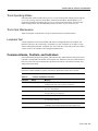
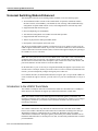
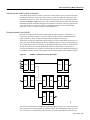
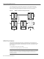
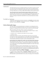
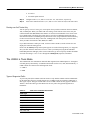
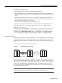
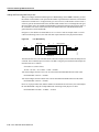
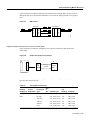
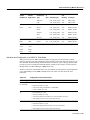
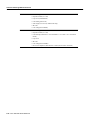
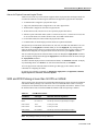
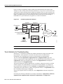
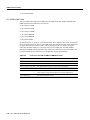
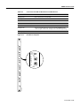
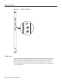
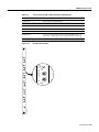
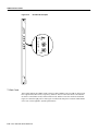
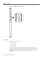
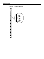
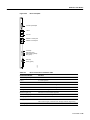
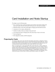
C H A P TER
4
Trunk Cards
This chapter describes the hardware and functionality of IGX trunk cards. The description of each
card includes:
•
•
•
Function
System interconnect
Faceplate indicators
Other publications that relate to IGX operation are:
•
The Cisco IGX 8400 Series Installation and Configuration publication describes installation,
troubleshooting, user commands, repair and replacement, and the rack-mount Cisco IGX
8420-to-IGX 8430 conversion.
•
The Cisco WAN Switching Command Reference publication and the Cisco WAN Switching
SuperUser Command Reference publication describe standard user commands and superuser
commands.
•
The Cisco WAN Manager Installation publication and the Cisco WAN Manager Operations
publication both contain information on network management.
Trunk Cards 4-1
Trunk Interface Cards
Trunk Interface Cards
This section describes the IGX trunks. The card groups are:
•
•
Universal switching module enhanced (UXM-E)
Network trunk module (NTM)
Note With Release 9.2 and later software, an Cisco IGX 8420 or 8430 switch can support a
maximum of 32 trunks.
Table 4-1 lists the trunk front cards, and Table 4-2 lists the corresponding trunk interface back cards.
Table 4-1
Trunk Front Cards
Card Acronym
Card Name
UXM-E
Universal switching module
NTM
Network trunk module
Table 4-2
Interface Back Cards for Trunks
Back Card Acronym by Trunk
Card Name
UXM-E
BC-UAI-4-155-MMF
4-port multimode fiber 155Mbps
BC-UAI-4-155-SMF
4-port single mode fiber 155Mbps
BC-UAI-2-155-SMF
2-port single mode fiber 155Mbps
BC-UAI-2-SMFXLR
2-port single mode fiber XLR
BC-UAI-4-SMFXLR
4-port single mode fiber XLR
BC-UAI-4-STM1E
4-port synchronous transport module-1E
BC-UAI-6-T3
6-port T3 back card
BC-UAI-3-T3
3-port T3 back card
BC-UAI-6-E3
6-port E3 back card
BC-UAI-3-E3
3-port E3 back card
BC-UAI-8-T1-DB-15
8-port T1 back card with DB-15 connector
BC-UAI-8-E1-DB-15
8-port E1 back card with DB-15 connector
BC-UAI-8-E1-BNC
8-port E1 back card with BNC connector
BC-UAI-4-T1-DB-15
4-port T1 back card with DB-15 connector
BC-UAI-4-E1-DB-15
8-port E1 back card with DB-15 connector
BC-UAI-4-E1-BNC
4-port E1 back card with BNC connector
NTM
BC-E1
E1 interface card
BC-T1
T1 interface card
BC-Y1
Y1 trunk interface card
BC-SR
Subrate trunk interface card
4-2 Cisco IGX 8400 Series Reference
Common Alarms, Controls, and Indicators
Trunk Operating Modes
IGX trunk cards operate in either simple gateway or cell forwarding mode. Simple gateway supports
service interworking, which lets Frame Relay connections terminate at ATM endpoints. For a
description of simple and complex gateways, service and network interworking, tiered networks,
trunks, ATM protocols, and cell and header formats, refer to the Cisco Systems Overview.
Trunk Card Maintenance
Trunk cards require no maintenance except for replacement after a confirmed failure.
Loopback Test
A trunk loopback test runs when an ATM trunk detects an integrated alarm. The loopback test
indicates if the line or the card is faulty. A loopback test “pass” means the line is faulty, so a line
alarm is subsequently indicated. A loopback test “fail” means the card is faulty. If the card is faulty,
a switch occurs to an available Y-cable equipped redundant card.
Common Alarms, Controls, and Indicators
Front cards and back cards have faceplates with indicator LEDs. Most cards have both a green Active
LED and a red Fail LED at the bottom of the faceplate. For definitions of the port status LEDs on a
back card, refer to the section that describes the back card. Table 4-3 describes the common card
status indicators for LEDs.
Note In slots where no back card exists, a blank faceplate must reside to block Electromagnetic
Interference (EMI) and Radio Frequency Interference (RFI) and to ensure correct air flow.
Table 4-3
Common Card Status Indicators
Indicators
Status
Meaning
Fail
ON Steady
Indicates an error occurred. First, reset the card with the resetcd f
command. If the LED comes on again, call the TAC.
Fail
Blinking
On an NPM in a redundant system, this combination indicates that
the card is being updated.
Active
ON steady
When steadily on, this combination indicates the card is active and
carrying traffic or processing data.
Active
ON momentarily
When momentarily on, indicates the card executed a self-test.
BOTH
OFF
Indicates the card is either part of a redundant pair and is in standby
or is not being used at all.
BOTH
ON
Indicates the card failed but remains active because no standby card
is available. One or more lines failed, but others remain active.
Trunk Cards 4-3
Universal Switching Module Enhanced
Universal Switching Module Enhanced
This description of the universal switching module (UXM-E) covers the following topics:
•
An introduction includes sections on the UXM-E mode of operation, trunk-mode features,
interface card list, card redundancy, card mismatch, clock sourcing, cellbus bandwidth usage,
configuration for public ATM network service, and configuration for cell trunk-only routes
•
•
•
•
•
•
Supported traffic and connection types
Inverse multiplexing over ATM (IMA)
Activation and configuration of a UXM-E for trunk-mode operation
Supported traffic and connection types
Alarms for physical lines and logical (IMA) trunks
Descriptions of the faceplates on the back cards
The universal switching module (UXM-E) can function in one of two modes. In trunk mode, the
UXM-E supports trunks in the network. In port mode, it as either an ATM User-to-Network Interface
(UNI) or a Network-to-Network interface (NNI). The back cards support multiple ports operating at
OC3/STM1, T3, E3, T1, or E1 rates.
Note The word “port” has two uses in a Cisco WAN switch. “Port mode” refers to the function of
an interface at the edge of a network—the endpoint at which you add connections (UNI) or the
interface between two networks (NNI). Examples of port cards are the UVM, UFM, ALM/A, and
port-mode UXM-E in an IGX switch or an ASI in a BPX switch.
On the other hand, a “port” is also a layer of logical functionality that applies to port cards as well
as trunk cards. For example, whether you activate a line to a router or activate an ATM trunk to the
network, you must subsequently configure the logical port in either case.
For a UXM-E, therefore, the documentation describes a logical “port” on a port-mode UXM-E for
a UNI or NNI at the edge of a network, yet it also refers to a “port on a UXM-E trunk” as a layer of
logic.
Introduction to the UXM-E Trunk Mode
The UXM-E can transport ATM cells to and from the cellbus at a maximum rate of 310 Mbps in
either direction. The UXM-E can support up to 8000 total connections in trunk mode.
Note The UXM-E in trunk mode cannot support more than 4000 gateway connections. All
remaining connections can be either user or networking connections. For example, if you configure
2500 gateway connections, you still have 5500 connections available to be used for user or
networking connections.
The UXM-E communicates only ATM cells to either the network or the CPE. On the cellbus,
however, the UXM-E communicates either ATM cells or FastPackets according to the card type.
With another UXM-E, it communicates only in ATM cells. With other cards, the UXM-E
communicates in FastPackets. Through its gateway functionality, the UXM-E translates between
FastPackets and ATM cells so it can transport voice, data, or Frame Relay traffic that other cards have
put in FastPackets.
4-4 Cisco IGX 8400 Series Reference
Universal Switching Module Enhanced
Determining the UXM-E’s Mode of Operation
The UXM-E detects reports its mode of operation to switch software when you first activate either
a trunk to the network or a line on the UNI or NNI. If you activate a trunk, the UXM-E goes into
trunk mode. If you activate a line, the UXM-E goes into port mode. The CLI commands for these
operations are uptrk and upln, respectively. (The UXM-E description in this chapter lists important
information about the commands that apply to the UXM-E, but the order of their use appears in the
Cisco IGX 8400 Series Installation guide. For a detailed description of each command and its
parameters, see the Cisco WAN Switching Command Reference.)
Example Networks with UXM-Es
Networks with both trunk mode and port mode UXM-Es appear in Figure 4-1 and Figure 4-2,
respectively. The nodes in Figure 4-1 use only UXM-Es for port interfaces and trunk interfaces.
Figure 4-2 shows a variety of cards providing interfaces for different traffic types.
The network carrying only ATM traffic appears in Figure 4-1. Each UXM-E trunk card in Figure 4-1
connects to either another UXM-E trunk card or a BXM operating as a trunk. The ATM UNI ports
are the UXM-E port cards (for connection A), the BXM operating in port mode (for connection B),
the ASI (for connection C), and the BXM feeder trunk (for connection D). Connection D is a
two-segment connection. One segment of connection D exists between the BNM and AUSM on the
Cisco MGX 8220 shelf, and the other segment exists between the BXM and the UXM-E UNI port.
Figure 4-1
UXM-Es in a Network with Pure ATM Traffic
A
B
UXM-E
UXM-E
UXM-E
UXM-E
A
ASI
C
C
D
IGX
BXM
BXM
BXM
BPX
BNI
BNI
BPX
BNM
BPX
AUSM
MGX 8220
D
29629
B
IGX
A network with ATM traffic and FastPacket-based traffic appears in Figure 4-2. Connections A and
B are ATM connections that terminate on UXM-E UNI port cards and a BXM operating as a UNI
port. Connection C is a Frame Relay connection between a UFM and an FRM. Connection D is a
Trunk Cards 4-5
Universal Switching Module Enhanced
voice connection between a CVM and CDP. Connection E is a local connection (DAXCON)
between a UFM and a UXM-E UNI port on the same node. For connections C–E, the gateway
function of the UXM-E packs and unpacks the FastPackets into and out of the ATM cells.
Figure 4-2
UXM-Es in a Network with Heterogeneous Traffic
A
A
UXM-E
BXM
UXM-E
BXM
B
IGX
B
UXM-E
BPX
UXM-E
UXM-E
UXM-E
UXM-E
UFM
C
IGX
IGX
IGX
CVM
NTM
UXM-E
D
E
29630
E
UXM-E Trunk Features
The following list broadly identifies the features of a UXM-E trunk. After the bulleted list, the
remaining sections of this introduction contain tables that list the features on particular topics, such
as interworking. Actual descriptions of the features appear in the section “The UXM-E in Trunk
Mode” on page 13.
•
•
The UXM-E uses all four lanes of the cellbus.
In trunk mode, the UXM-E supports up to 8000 connections.
Note The UXM-E in trunk mode cannot support more than 4000 gateway connections. All
remaining connections can be either user or networking connections. For example, if you configure
2500 gateway connections, you still have 5500 connections available to be used for user or
networking connections.
4-6 Cisco IGX 8400 Series Reference
Universal Switching Module Enhanced
•
The maximum throughput is 310 Mbps—two times the OC-3 (STM1) rate. This maximum
applies whether the back card is a 2-port or 4-port back card. In practical application, this
maximum rate means that most trunk applications with an OC-3 interface would use the 2-port
back card.
•
•
The UXM-E supports ATM-to-Frame Relay network and service interworking.
•
•
•
The UXM-E supports Y-cable redundancy with hot standby for very fast switchover.
•
The UXM-E can form a logical trunk by grouping more than one T1 or E1 port. The name of this
(purchased) option is Inverse Multiplexing over ATM (IMA).
•
The on-board diagnostics are loopback, self-test, and background.
For the ABR connection types, the UXM-E supports EFCI marking, Explicit Rate Stamping, and
Virtual Source/Virtual Destination (VS/VD).
The front card has 128K cell buffers.
For statistics support, the UXM-E provides real-time statistics counters and interval statistics
collection for ports, lines, trunks, and channels.
UXM-E Interfaces
Table 4-4 is a list of the UXM-E back cards. Figure 4-3 shows the UXM-E front card. Table 4-5
defines all possible combinations for the states of the front card status LEDs (Fail, Active, and
Standby).
Table 4-4
Back Cards for the UXM-E
Card Name
Card Description
BC-UAI-4-155-MMF
4-port multimode fiber 155 Mbps
BC-UAI-4-155-SMF
4-port single mode fiber 155 Mbps
BC-UAI-2-155-SMF
2-port single mode fiber 155 Mbps
BC-UAI-2-SMFXLR
2-port single mode fiber XLR
BC-UAI-4-SMFXLR
4-port single mode fiber XLR
BC-UAI-4-STM1E
4-port synchronous transport module-1E
BC-UAI-6-T3
6-port T3 back card
BC-UAI-3-T3
3-port T3 back card
BC-UAI-6-E3
6-port E3 back card
BC-UAI-3-E3
3-port E3 back card
BC-UAI-4-T1-DB-15
4-port T1 back card with DB-15 connector
BC-UAI-8-T1-DB-15
8-port T1 back card with DB-15 connector
BC-UAI-4-E1-DB-15
4-port E1 back card with DB-15 connector
BC-UAI-8-E1-DB-15
8-port E1 back card with DB-15 connector
BC-UAI-4-E1-BNC
4-port E1 back card with BNC connector
BC-UAI-8-E1-BNC
8-port E1 back card with BNC connector
Trunk Cards 4-7
Universal Switching Module Enhanced
Figure 4-3
UXM-E Front Card
Minor
Major
Fail
Active
Standby
29424
UXME
4-8 Cisco IGX 8400 Series Reference
Universal Switching Module Enhanced
Table 4-5
UXM-E Status LEDs
Fail
Active
Standby
Status of Card
On
Off
Off
Failed
Blinking
Blinking
Off
Back Card Mismatch (hot standby)
Blinking
On
Off
Back Card Mismatch (active)—can be missing back card
Blinking
Off
Blinking
Back Card Mismatch (self-test)
Blinking
Off
On
Back Card Mismatch (standby)
Off
Blinking
Off
Hot Standby
Off
On
Off
Active
Off
Off
Blinking
Self-test
Off
Off
On
Standby
On
On
On
Down
Maximum Number of UXM-Es
Switch software limits the number of logical trunks and ports on an IGX switch. The maximum
number of UNI or NNI ports in an IGX switch is 64. The maximum number of logical trunks is 32.
To determine the number of each logical type in the switch, add the number of ports on multiport
cards and single-port cards. These sums cannot exceed 64 ports and 32 trunks. For example, using
exclusively 2-port OC3 trunks, you could install:
2 trunks per card x 16 OC3 UXM-Es = 32 trunks
Switch software monitors the number of logical ports and trunks, not the number of UXM-Es.
Therefore, the software keeps you from activating an excessive number of lines or trunks on the node
rather than flagging the presence of too many cards.
Y-Cabled UXM-E Redundancy
The UXM-E features hot standby as a part of its Y-cable redundancy capability. With hot standby,
the redundant card receives the configuration information as soon as you finish specifying
redundancy. The standby card also receives updates to its configuration as the active card
configuration changes. Hot standby lets the backup card go into operation as soon as necessary rather
than waiting for the NPM to download the configuration.
Y-cable redundancy requires that both cards are active and available before you set up redundancy.
Use Cisco WAN Manager or the CLI commands uptrk, addtrk, then addyred. (See also
descriptions of addyred, delyred, dspyred, and ptyred in the Cisco WAN Switching Command
Reference publication.)
Switchover to a Redundant UXM-E
If the card fails, a switchover occurs to a Y-cabled, redundant UXM-E card set if available. If the
switchover occurs, the primary UXM-E acquires failed status, and the Fail LED turns on.
Trunk Cards 4-9
Universal Switching Module Enhanced
Card Mismatch
The UXM-E supports two types of card mismatch notification. The notification common to all cards
occurs when you connect an unsupported back card to the front card. The mismatch notification
unique to the UXM-E occurs if you attach a supported back card but one that has a different interface
or a smaller number of the correct line types than what the UXM-E previously reported to software.
The UXM-E informs switch software of the number and type of interface ports when you first
activate a UXM-E. Software retains the back card configuration data if you remove it. If you
subsequently attach a card with fewer ports, switch software flags a mismatch. Replacing a back card
with more ports of the same line type or exchanging SMF and MMF OC3 (STM1) cards is not a
mismatch. To change the interface that software has on record, you must first down the card then
reactivate it.
The UXM-E as a Clock Source
A UXM-E line or trunk can be the clock source for the node. Use the dspclksrcs command to display
available clock sources, dspcurclk to show the current clock source, and cnfclksrc to specify a new
clock source. To clear clock alarms, use clrclkalm.
Cellbus Bandwidth Usage
The cellbus consists of four operational lanes plus one backup lane. (The backup lane becomes
active if a lane fails.) The FastPacket-based cards can use only one lane and communicate only in
FastPackets. If a FastPacket-based card controls the cellbus, no ATM cells can be on the cellbus.
When the UXM-E has control of the cellbus, it can pass any of the following:
•
ATM cells on all lanes (for example, with a daxcon between UXM-Es or when one UXM-E
communicates with another UXM-E in the same switch)
•
•
FastPackets on lane 1 simultaneously with ATM cells on lanes 2 through 4
FastPackets on lane 1
Switch software monitors and computes cellbus bandwidth requirements for each card in the
Cisco 8400 series switches. For the UXM-E alone, you can change its cellbus bandwidth allocation.
(You cannot view or alter bandwidth allocation for other cards.) The unit of measure for the ATM
cell and FastPacket bandwidth on the cellbus is the universal bandwidth unit (UBU).
Switch software allocates a default number of UBUs for the card when the UXM-E identifies the
back card interface to switch software. If you remove a card, switch software reserves the current
cellbus bandwidth allocation for that card. If, as you add more connections, the load approaches
oversubscription, switch software displays a warning message. Regardless of the warning message,
Cisco recommends that you monitor bandwidth allocation and allocate more UBUs for the card to
avoid oversubscription.
For the UXM-E, switch software allocates enough bandwidth to meet the requirements for the
minimum cell rate (MCR) and therefore does not accommodate burstiness. Therefore, you must
know the UXM-E bandwidth requirements to determine if you should change its UBU allocation.
Monitor the bandwidth requirements after you build the network and during normal operation. On
the CLI, the applicable commands are cnfbusbw and dspbusbw.
You can raise, lower, or check a UXM-E’s UBUs with cnfbusbw. The cnfbusbw privilege level is
0—superuser. To check a UXM-E’s UBUs, use dspbusbw or cnfbusbw. Any user can use
dspbusbw. Each command’s display provides the information you need to determine if you must
increase the UBUs on a particular UXM-E. The only value you can change is allocated bandwidth.
4-10 Cisco IGX 8400 Series Reference
Universal Switching Module Enhanced
The card-based default and maximum cellbus bandwidth for each interface appears in Table 4-5.
Note that FastPackets require substantially less cellbus bandwidth than ATM cells. The FastPacket
requirements in the figure and table reflect the restriction of FastPackets to one lane and the
maximum processing rate of the gateway on the UXM-E.
The values you can view with the cnfbusbw and dspbusbw commands are:
Table 4-6
•
Minimum Required Bandwidth, the necessary bandwidth that switch software has calculated for
the existing connections on the local UXM-E. The display shows the requirements for
FastPackets, ATM cells, and the equivalent in total UBUs.
•
•
•
Average Used Bandwidth is the average bandwidth usage.
•
Allocated Bandwidth is the current cellbus allocation for the card. The field shows the UBUs, the
bandwidth when only ATM cells are on the bus, and cells plus Fastpackets. The reason for cells
alone and cells plus Fastpackets is that cells can exist on the cellbus with or without FastPackets.
The last field under Allocated Bandwidth shows the formula to which the allocated values must
adhere. (A description of the formula follows the example screen.)
Peak Used Bandwidth is the peak bandwidth usage.
Maximum Port Bandwidth is the maximum bandwidth that the back card can support. The
FastPackets per second field has a dash-mark because only cells pass through the port.
Cellbus Bandwidth Allocation for UXM-E Interfaces
Max.
UBUs
Max.
Cell
Traffic
Only
(cps)
Maximum
Cell + Fpkts
Traffic
(cps and fps)
Interface
Type
Ports
Default
UBUs
Default
Cell
Traffic
Only
(cps)
OC3
4 or 2
44
176,000
132,000, 88,000
235
708,000
473,000, 470,000
T3
6 or 3
24
96,000
72,000, 48,000
235
708,000
473,000, 470,000
E3
6 or 3
20
80,000
60,000, 40,000
235
708,000
473,000, 470,000
T1
8
8
32,000
24,000, 16,000
32
128,000
96,000, 64,000
T1
4
4
16,000
12,000, 8,000
16
64,000
48,000, 32,000
E1
8
10
40,000
30,000, 20,000
40
160,000
120,000, 80,000
E1
4
5
20,000
15,000, 10,000
20
80,000
60,000, 40,000
Default
Cell + Fpkt
Traffic
(cps and fps)
Planning for Cellbus Bandwidth Allocation
With the Network Modeling Tool™ (NMT), you can use the projected load for all UXM-Es in the
network to estimate their cellbus requirements. During normal operation, you can use Cisco WAN
Manager to obtain the trunk and port statistics then decide whether to use cnfbusbw to increase the
UBU allocation. If you are using only the CLI, you would need to establish a virtual terminal (vt)
session to each node then execute dspbusbw or cnfbusbw.
Trunk Cards 4-11
Universal Switching Module Enhanced
Calculating Cellbus Bandwidth Changes
To determine how many UBUs are necessary, use the values for average bandwidth used in the
following formula:
fps
-------- + cps
2
UBUs = ----------------------4000
In most circumstances, the fps and cps values from average bandwidth used are sufficient. The peak
bandwidth used values are primarily informational.
The information in Table 4-5 provides the ranges for the interface type. Note that, if you do the math
according to the formula, you see that the value in the cells-alone column of Table 4-5 equals the
result of adding half the FastPacket value to the cell value in the cells plus FastPackets column.
When you use dspbusbw, a yes/no prompt asks if you want firmware to retrieve the usage values. If
you enter a “y,” the UXM-E reads—then clears—its registers and thus restarts statistics gathering.
If you enter an “n,” switch software displays the current values that reside in control card memory
(on the NPM). The values in memory come from the last update from the UXM-E.
ATM Across a Public ATM Network
The UXM-E can support trunking across a public ATM network so both virtual channel connections
(VCCs) and virtual path connections (VPCs) traverse a single virtual path trunk. This feature lets
you map multiple trunks to a single port of an NNI. The NNI connects to either a public or private
ATM network. The virtual trunk package is a lower-cost alternative to leased circuits but still has the
full set of Cisco ATM traffic management capabilities. This application requires two UXM-Es and
a clock from an external source. The rates can be OC-3/STM-1, T3/E3, or T1/E1.
UXM-Es Configured for a Public ATM Network
1
UXM-E
trunk
Cable
2
1
2 UXM-E 4
port
3
3
slot 8
Public
network
slot 9
10106
Figure 4-4
Note the following characteristics of this form of trunking across a public network:
•
•
•
The trunk cannot provide the a clock for transport across the public network.
This feature does not support VPC connections across the public network.
The node number at each endpoint must be 17 or higher.
Refer to Figure 4-3 as you read the steps for the following example set-up:
Step 1
Connect a cable between each of the following:
•
•
8.1 and 9.1
8.2 and 9.2
4-12 Cisco IGX 8400 Series Reference
Universal Switching Module Enhanced
•
•
8.3 and 9.3
9.4 and the public network
Step 2
Configure trunk 8.1, 8.2, and 8.3 to use VPC 101, 102, and 103, respectively.
Step 3
Add 3 VPC connections from 9.1, 9.2, and 9.3 to 9.4. At the far end, use the same VPCs.
Routing over Cell Trunks Only
You can specify trunk cell routing only as an option when you add a connection between UXM-E,
ASI, or BXM ports. When you enable trunk cell routing, switch software routes across only the
cell-based trunk cards BNI, BXM, and UXM-E: no conversion to FastPackets occurs on the route.
If you disable trunk cell routing, the routing process can select a FastPacket-based trunk and so
decrement the number of available gateway connections. Also, using a FastPacket-based trunk may
result in increased network delays. Therefore, enabling trunk cell routing is the preferred choice
when you add a connection at a BNI, BXM, or UXM-E.
If you add connections at other port cards, such as a UFM or ALM/A, switch software does not
display the trunk cell routing option.
On the CLI, the addcon prompt for this option appears as “trunk cell routing restrict y/n?” It appears
after you enter either the ATM class of service or after you finish specifying all the individual
bandwidth parameters that apply to the current connection type. You can specify whether the default
for trunk cell routing is “Yes” or “No” through the cnfnodeparm (superuser) command.
The UXM-E in Trunk Mode
The UXM-E trunk can communicate ATM cells that originated at an ATM endpoint or—through its
on-board gateway functionality—FastPacket-based traffic such as voice, data, and Frame Relay. A
UXM-E trunk can connect to the following trunk cards:
•
•
UXM-E
BXM
Types of Supported Traffic
As previously stated, the UXM-E trunk can connect to only another UXM-E trunk or a BXM trunk.
On the other hand, the types of traffic that traverse a UXM-E trunk can originate at ATM ports or
other types of ports. The types of traffic that a cell on a UXM-E trunk can carry appear in Table 4-7.
Table 4-7 shows the traffic types that ATM cells can carry where the payload originated as a
FastPacket.
Table 4-7
Traffic from FastPacket-Based Cards
Traffic Type
Timestamped
Non-timestamped
Voice
Bursty data A
Bursty data B
High priority
CBR, VBR, ABR
Trunk Cards 4-13
Universal Switching Module Enhanced
Types of Connections on a UXM-E Trunk
This section introduces the connections that a UXM-E trunk supports. The context of each
description is the trunk rather than the connection endpoints. The purpose of these descriptions is
not only to inform but also help you plan the network. Some definitions overlap because a connection
may qualify as more than one type.
•
A Cell connection carries information that exists in ATM cell format throughout the path. On a
UXM-E trunk, therefore, the only cell connections are those that have originated on a UXM-E
port at one end and remain in cell format throughout the connection.
•
A Gateway connection carries information that normally exists in ATM cell format but is
translated to FastPacket format for some purpose at some point along the path. Reason for the
translation could be that the connection terminates on a FastPacket-based card, is a network
connection, or includes a FastPacket-based trunk card in the route.
•
A Networking connection carries network messages between nodes and terminate as FastPackets
(and therefore are also gateway connections).
•
A User-connection is a connection that a user has added at the current node. User-connections
can be cell connections or gateway connections. User connections are mutually exclusive of via
connections and network connections.
•
A Via connection passes through a node and does not terminate on the node. You can neither view
nor alter a via connection because the connection does not terminate on the node (the node that
owns the connection has made the via node and trunk a part of the route).
•
An Interworking connection is a service or network interworking connection in which one end
terminates as ATM and the other as Frame Relay. Interworking connections are a subset of
gateway connections.
Operating as a trunk, the UXM-E carries up to 8000 connections. A via connection can be either a
cell-type or a gateway-type.
Because network messages use gateway channels, they subtract from the total number of available
gateway connections. For each active port, the UXM-E reserves 270 gateway connections for
networking regardless of the interface type. Therefore, with a fully-utilized 8-E1 or 8-T1 back card,
the UXM-E reserves up to 2160 connections. Because these numbers potentially represent a very
significant reduction in the number of gateway connections for user-data, switch software lets you
specify a maximum number of active ports on the back card. The most applicable interfaces for this
capability are the T1 and E1 ports, especially with Inverse Multiplexing Over ATM (IMA). See the
section “Inverse Multiplexing over ATM on IGX Trunks” for the description of IMA.
You can specify the maximum number of logical trunks that can be active on a card through Cisco
WAN Manager or the CLI. The applicable CLI command is cnftrkport. For example, if you intend
an eight-port card to have two logical (IMA) trunks, you can use cnftrkport to specify a maximum
number of two trunks. Software would therefore reserve 540 connections for network messages
rather than the 2160 connections if you did not specify a maximum.
Inverse Multiplexing over ATM on IGX Trunks
Inverse Multiplexing over ATM (IMA) lets you group physical T1 or E1 lines to form a logical trunk.
A logical trunk consisting of more than one T1 or E1 line supports connections with data rates that
are much higher than the T1 or E1 rate. System software lets you specify IMA so that one or more
physical lines within the logical trunk can serve as backup if a line fails.
4-14 Cisco IGX 8400 Series Reference
Universal Switching Module Enhanced
IMA characteristics are as follows:
•
•
All physical ports of an IMA trunk use the same line configuration.
The node maintains a set of retained links for the IMA trunk to keep it active. The IMA trunk
does not fail unless the number of active trunks is less than the user-specified number of retained
links.
•
The IMA trunk can provide a clock source or clock path (see cnftrk command). The first (the
lowest numbered) available physical line is used. If this line fails, the next available line within
the IMA provides the clock source or clock path.
•
Full support for individual physical line alarms and statistics.
To specify the range of ports for an IMA trunk, you can use either Cisco WAN Manager or the
command-line interface (CLI). To define an IMA trunk on the CLI, use the uptrk command:
uptrk slot.start_port-end_port
For example, you could enter uptrk 8.1–4. Subsequently, you would refer to this logical trunk by
using only the slot number and first port number—8.1 in this example—when you use other
commands, such as addtrk, deltrk, cnftrk, and so on. Commands for viewing IMA information
also include dspportstats, dspphyslns, dsptrkcnf, dspfdr, dspnode, and dspphyslnstathist.
Adding an IGX Feeder
The IMA feeder node feature provides redundancy in case one of the physical lines on an IMA trunk
fails. This reduces the chance of a single point of failure when a single feeder trunk is out of service.
In addition, this feature allows you to configure the services on a feeder node instead of a routing
node.
Figure 4-5 shows an example of an IGX feeder topology.
Sample IGX Feeder Topology
IGX-feeder
U
F
M
IGX-hub
U
X
ME
U
X
ME
U
X
ME
IGX-hub
IMA cloud
U
X
ME
U
X
ME
29454
Figure 4-5
IMA-trunk 8.3-8
Currently supported on the IGX, a Service Expansion Shelf (SES) can function as a feeder node
connected to an IGX routing node using a UXM-E OC-3 interface. The UXM-E feeder node feature
adds the capability to support the UXM-E interface and the IGX as a feeder node. The routing node
can be an IGX or a BPX/BXM-T3, BPX/BXM-E3, or BNI. The UXM-E interface type T1/E1,
nxT1/E1, T3/E3, and OC-3, SMF/MMF Extra Long Reach can be used to connect an IGX feeder
node to the IGX/BPX routing node.
Note For a summary of commands you use to bring up an IGX node, refer to the section “IGX
Configuration Summary” in Cisco IGX 8400 Series Installation and Configuration.
Trunk Cards 4-15
Universal Switching Module Enhanced
Adding and Removing IMA Group Links
When you configure an IMA trunk through Cisco WAN Manager or the cnftrk command, you enter
the number of retained links. This represents the number of ports that must remain active for the IMA
trunk itself to remain active. If a physical line goes out of service, but the number of active lines is
at least as great as the retained links value, the IMA trunk remains active even though the node goes
into major alarm. Also, the available load bandwidth is adjusted according to physical line status, so
the switch does not reroute connections after a line failure unless the used bandwidth becomes
greater than the available bandwidth.
In Figure 4-6, the number of retained links is set to 3. If line 1 fails for example, trunk 8.1-4 will
continue functioning, however, the node will show major alarm due to the physical line failure.
Line Redundancy
4
IGX-Hub
6
1
U
X
ME
U
X
ME
1
IGX-Feeder
5
2
6
3
U
X
ME
Trunk 8.1-4
U
X
ME
6
1
29452
Figure 4-6
The transmit and receive rate of an IMA trunk is the sum of all physical lines minus the IMA protocol
overhead. The overhead for up to four lines is one DS0. Using the previous IMA trunk example, the
maximum rates are as follows:
for trunk 8.1-4 (with T1 lines):
TX rate = Rx rate = 24 * 4 DS0s – 1 DS0 = 95 DS0s
You could configure the line receive rate to be the maximum bandwidth allowed on this trunk:
total bandwidth = RX rate = 95 DS0s
You could configure the line transmit rate to be the maximum bandwidth allowed on this trunk:
total bandwidth = RX rate = 95 DS0s
However, if a physical line fails (and the number of retained links are still active), the switch adjusts
the total bandwidth. Using the example IMA trunk consisting of four physical T1 lines:
total bandwidth is 95 DS0s – 24 DS0s = 71 DS0s
4-16 Cisco IGX 8400 Series Reference
Universal Switching Module Enhanced
Figure 4-7 shows an example of IMA protocol overhead. In the example, DS0 1 is reserved for an
IMA group with 1 to 4 physical lines and DS0 2 is reserved for an IMA group with 5 to 8 physical
lines.
IMA Protocol
IGX-hub
6
1
U
X
ME
U
X
ME
5
1
IGX-feeder
6
2
U
X
ME
3
4
U
X
ME
6
1
29453
Figure 4-7
Trunk 8.1-4
Supported Segment Connections on the IGX Feeder Node
Figure 4-8 shows an example of configuring a two-segment connection for IGX feeder node
functionality.
Figure 4-8
Sample Two-Segment Connections
A
U
X
ME
BNI/
BXM/
UXM-E
Routing
network
UXM-E/
BXM
29455
B
IGX-feeder
Table 4-8 lists the corresponding routing and feeder endpoints with applicable gateway and load
types and also connection types.
Table 4-8
Two-Segment Connections
Routing
Endpoint A
Feeder
Endpoint B
Connection
Type
VCC
or
VPC
Gateway Type
Cell
Routing
Load Type
UXM-E
UXM-E
CBR
Both
GW_TYPE_NONE
True
CBR_LOAD
RT-VBR
GW_TYPE_NONE
True
CBR_LOAD
NRT-VBR
GW_TYPE_NONE
True
VBR_LOAD
ABR.STD
GW_TYPE_NONE
True
ABR_LOAD
ABRFST
GW_TYPE_NONE
True
ABR_LOAD
UBR
GW_TYPE_NONE
True
UBR_LOAD
GW_TYPE_NWI
N/A
BDATA_LOAD
BXM
UXM-E
UXM-E
ATFR
N/A
Trunk Cards 4-17
Universal Switching Module Enhanced
Routing
Endpoint A
Feeder
Endpoint B
BXM
Connection
Type
VCC
or
VPC
ATFST
UXM-E
UFM
FRM
Gateway Type
Cell
Routing
Load Type
GW_TYPE_NWI
N/A
BDATB_LOAD
UFM
ATFR
N/A
GW_TYPE_NWI
N/A
BDATA_LOAD
FRM
ATFST
N/A
GW_TYPE_NWI
N/A
BDATB_LOAD
UFM
ATFR
N/A
GW_TYPE_NWI
N/A
BDATA_LOAD
ATFST
N/A
GW_TYPE_NWI
N/A
BDATB_LOAD
ATFX
N/A
GW_TYPE_SIWX
N/A
BDATA_LOAD
ATFXFST
N/A
GW_TYPE_SIWX
N/A
BDATB_LOAD
ATFT
N/A
GW_TYPE_SIWT
N/A
BDATA_LOAD
ATFTFST
N/A
GW_TYPE_SIWT
N/A
BDATB_LOAD
ATFR
N/A
GW_TYPE_NWI
N/A
BDATA_LOAD
FRM
Note Two-segment voice and data connections are not supported.
Figure 4-9 shows an example of configuring a three-segment connection for IGX feeder node
functionality.
Figure 4-9
Sample Three-Segment Connections
A
B
BXM/
UXM
Routing
network
BXM/
UXM
U
X
ME
29551
U
X
ME
IGX-feeder
IGX-feeder
Table 4-9 lists the corresponding feeder endpoints with applicable gateway and load types and
connection types.
Table 4-9
Three-Segment Connections
Feeder
Endpoint A
Feeder
Endpoint B
Connection
Type
VCC
or
VPC
Gateway Type
Cell
Routing
Load Type
UXM-E
UXM-E
CBR
Both
GW_TYPE_NONE
True
CBR_LOAD
RT-VBR
GW_TYPE_NONE
True
CBR_LOAD
NRT-VBR
GW_TYPE_NONE
True
VBR_LOAD
ABR.FST
GW_TYPE_NONE
True
ABR_LOAD
4-18 Cisco IGX 8400 Series Reference
Universal Switching Module Enhanced
Feeder
Endpoint A
Feeder
Endpoint B
Connection
Type
VCC
or
VPC
Gateway Type
Cell
Routing
Load Type
ABR.STD
GW_TYPE_NONE
True
ABR_LOAD
UBR
GW_TYPE_NONE
True
UBR_LOAD
GW_TYPE_NWI
N/A
BDATA_LOAD
UXM-E
UXM-E
ATFR
Both
UFM
UFM
ATFST
GW_TYPE_NWI
N/A
BDATB_LOAD
ATFX
GW_TYPE_SIWX
N/A
BDATA_LOAD
ATFXST
GW_TYPE_SIWX
N/A
BDATB_LOAD
ATFT
GW_TYPE_SIWT
N/A
BDATA_LOAD
ATFTST
GW_TYPE_SIWT
N/A
BDATB_LOAD
UXM-E
UXM-E
ATFR
N/A
GW_TYPE_NWI
N/A
BDATA_LOAD
FRM
FRM
ATFST
N/A
GW_TYPE_NWI
N/A
BDATB_LOAD
UVM
UVM
CBR
N/A
GW_TYPE_NONE
N/A
CBR_LOAD
CVM
CVM
HDM
HDM
LDM
LDM
Activation and Configuration of a UXM-E in Trunk Mode
When you insert a new UXM-E into the backplane or apply power to the IGX node, UXM-E
firmware reports the card type and number of physical lines on the back card. Switch software can
then determine the allowed range and characteristics of trunks for you to configure. Software thus
prevents you from exceeding the maximum number of trunks on the switch as you activate them
through either Cisco WAN Manager or uptrk on the CLI.
Table 4-10 shows the trunk characteristics you can configure for each interface type through either
Cisco WAN Manager or the cnftrk command on the CLI. Table 4-10 also shows the fixed
parameters.
Table 4-10
Configurable Trunk Characteristics
Interface Type
Configurable Parameters
OC3 (STM1) SMF,
EL, and MMF
• HCS masking (on or off)
• Payload scramble (on or off)
• Cell (line) framing (STS/SONET or STM/SDH)
• Frame scramble (on or off)
T3
• HCS masking (on or off)
• Payload scramble (on or off)
• Cell (line) framing can be header error correction (HEC) or PLCP
• Cable length (0 to 255 feet or greater than 255 feet)
E3
• HCS masking (on or off)
• Payload scramble (on or off)
• Cell (line) framing is fixed as header error Correction (HEC)
• Cable length (0 to 255 feet or greater than 255 feet)
Trunk Cards 4-19
Universal Switching Module Enhanced
T1
• HCS masking (on or off)
• Payload scramble (on or off)
• Loop clock (enable/disable)
• Line framing (ESF or D4)
• Cable length (0 to 655 feet, ABAM cable only)
• Idle code
• Line coding (fixed as B8ZS)
E1
• HCS masking (on or off)
• Payload scramble (on or off)
• Line DS0 map (timeslots 0 to 31 for unframed or 1 to 15 and 17 to 31 for framed
format)
• Loop clock
• Idle code
• Line coding (fixed as HDB3)
• Receive line impedance (BNC fixed at 75 ohms; DB-15 fixed at 120 ohms)
4-20 Cisco IGX 8400 Series Reference
Universal Switching Module Enhanced
Alarms for Physical Lines and Logical Trunks
Variations exist in the way switch software supports alarms for physical lines and logical trunks for
a trunk-mode UXM-E. The following list summarizes the approach to physical lines and trunks:
•
•
•
•
•
A UXM-E trunk is mapped to a physical line object.
•
•
For non-IMA trunks, the alarm includes the physical line alarm.
A physical (non-IMA) trunk is mapped one-to-one with a physical line.
An IMA trunk is mapped to more than one physical line.
All line alarms (LOS, LOP, and so on) are reported as physical line alarms.
Software reports other trunk alarms (such as communication failure, communication break, and
so on) as trunk alarms in a manner similar to other, non-UXM-E trunk alarms.
For IMA trunks, the trunk and physical line alarms are separate and distinct.
The physical layer trunk alarms include LOS, LOF, AIS, Yel, LOP, Path AIS, and Path Yel. To view
these alarms, use the dspphysln command. When you execute dspphysln, any existing alarms
appear as the physical line status. For a trunk with one physical line (such as an OC3 trunk or T1/E1
without IMA configured), the integrated alarm status is also shown by the dsptrks command.
You can enable the physical line statistical alarm on the CLI through the cnfphyslnalm command.
You can display existing alarms through the dspphyslnerrs command and clear the alarms through
the clrphyslnalm command.
To enable or disable the physical line or trunk statistical alarms, use cnftrkalm command. To display
any outstanding alarms, use dstrkerrs. To clear the statistical alarms, use clrtrkalm.
To see the physical line and trunk statistical alarm types that apply to the UXM-E, enter the
commands for configuring the alarms.
In summary, the applicable commands are dspphyslns, dspphyslnerrs, clrphyslnalm, cnflnalm,
dsptrks, dsptrkerrs, cnftrkalm, clrtrkalm, dspalms.
SCR and PCR Policing at Less than 50 CPS on UXM-E
This section provides descriptions of lowered PCR minimum policing values supported by the BXM
and UXM-E. When policing is off, connections can be set with PCR values as low as 6 cells per
second (CPS). The minimum SCR value can be set to 6 CPS regardless of interfaces. Table 4-11 lists
the minimum PCR values for different BXM and UXM-E cards when policing is enabled.
Table 4-11
PCR Minimum Values
Card Name
Card Type
Minimum PCR Policing Values
BXM
T3/E3
12 cells per second
BXM
OC-3/OC-12
50 cells per second (or equivalently 19.2 kbps)
IGX-UXM-E
T1/E1
6 cells per second
IGX-UXM-E
T1/E1 IMA
6 cells per second
IGX-UXM-E
OC-3/STM-1
50 cells per second (or equivalently 19.2 kbps)
Note The policing accuracy is always within 1%.
Trunk Cards 4-21
Universal Switching Module Enhanced
Figure 4-10 shows an application example enabled by the PCR minimum value feature. In the
example, less than 19.2 kbps Frame and ATM connections are set up across two carrier Frame and
ATM networks with the policing function enabled at the boundary of the two carrier networks. The
PCR value of segment 2 is set to the new minimum PCR policing value supported by the NNI facing
BXM. For the BXM cards where the minimum PCR values are lowered, over-provisioning of
bandwidth for low speed connections (on segment 2) is reduced or eliminated.
PCR Policing Application Example
Segment 1
Segment 2
FR end device
Policing enabled
BPX
FRSM
BXM
BXM
NNI
Public
ATM/FR network
< 19.2 kbps FR/ATM SIW
or NIW connections
FR or
ATM server
IGX
UFM
FR end device
UXM-E
NNI
Policing enabled
Note Firmware revision Model B must be used on all cards to avoid card mismatch.
Trunk Statistics for Troubleshooting
In Release 9.3, switch software separates the UXM-E trunk statistics into physical statistics and
logical statistics. (This separation is a deviation from other schemes for trunk statistics
management.) The commands in this section are useful primarily for troubleshooting.
The CLI commands cnfphyslnstats, dspphyslnstatscnf, and dspphyslnstathist apply to the
statistics for physical lines within an IMA trunk. You can enable the physical line statistics by using
cnfphyslnstats, display the configuration for statistics with dspphyslnstatcnf, and display the
statistics themselves with dspphyslnstathist.
The logical trunk statistics includes Qbin statistics, VI statistics, and gateway statistics. To enable
statistics using the Cisco WAN Manager, you must use the TFTP mechanism. To configure the
logical trunk statistics through the CLI, use cnftrkstats. The dsptrkstatcnf command shows the
configuration of the trunk statistics. To display the logical trunk statistics, use dsptrkstathist. These
three commands primarily apply to debugging.
Software also supports statistics for trunk ports. Use the dspportstats command to display these
statistics.
In summary, the following commands let you manage trunk statistics: cnfphyslnstats, cnftrkstats,
dspphyslnstatcnf, dspphyslnstathist, dsptrkstatcnf, dsptrkstathist, and dspportstats.
4-22 Cisco IGX 8400 Series Reference
31230
Figure 4-10
UXM-E Interface Cards
Summary Statistics
You can view summary statistics for a UXM-E trunk through Cisco WAN Manager or the CLI. The
CLI commands are dspportstats and dsptrkstats.
With dspportstats, you can view:
•
•
•
Port statistics
IMA statistics
ILMI/ILMI statistics
With dsptrkstats, you can view:
•
•
•
Qbin statistics
Gateway statistics
Virtual interface statistics
UXM-E Interface Cards
This section provides basic information on the interface back cards for the UXM-E. The information
consists of a general description, an illustration of the card faceplate, and a table describing the
connectors and status LEDs. For details on the line technology of each type of interface, see the
appendix “System Specifications.”
Note The T1 and E1 back cards do not have Active and Fail LEDs to indicate card status (rather
than the port status indicated by the tri-color LEDs). If a T1 or E1 back card failure is detected, all
of the tri-color LEDs turn red.
The model numbers of the back cards and the order of their appearance are:
•
•
•
•
•
•
•
•
•
•
•
•
•
•
•
BC-UAI-4-155-MMF
BC-UAI-4-155-SMF
BC-UAI-2-155-SMF
BC-UAI-2-SMFXLR
BC-UAI-4-SMFXLR
BC-UAI-4-STM1E
BC-UAI-6-T3
BC-UAI-3-T3
BC-UAI-8-T1-DB-15
BC-UAI-4-T1-DB-15
BC-UAI-6-E3
BC-UAI-3-E3
BC-UAI-8-E1-DB-15
BC-UAI-8-E1-BNC
BC-UAI-4-E1-DB-15
Trunk Cards 4-23
UXM-E Interface Cards
•
BC-UAI-4-E1-BNC
OC-3/STM1 Back Cards
The OC3/STM1 back cards for the UXM-E have the single-mode fiber (SMF), multimode fiber
(MMF) and electrical connections. The cards are:
•
•
•
•
•
•
BC-UAI-2-155-SMF
BC-UAI-4-155-SMF
BC-UAI-4-155-MMF
BC-UAI-2-SMFXLR
BC-UAI-4-SMFXLR
BC-UAI-4-STM1E
As indicated by the “2” or the “4” in the model number, these cards have two or four transmit and
receive connectors. Each line has a tri-color LED whose color indicates its status. Each card also has
a red Fail LED and a green Active LED to indicate the status of the card. Table 4-12 lists the
connectors and LEDs. Figure 4-11 shows the four-port OC3/STM1 card. The SMF, STM1E,
SMFXLR, and MMF versions appear the same. Figure 4-12 shows the two-port OC3/STM1 card.
For technical data on OC3/STM1 lines, see the appendix “System Specifications.”
Table 4-12
Connectors and LEDs for SMF and MMF Back Cards
Connector/Indicator
Function
Transmit and receive
SC connector for SMF and MMF
Red (on the tri-color LED)
On indicates line is active but a local alarm was detected.
Yellow (on the tri-color LED)
On indicates line is active but a remote alarm was detected.
Green (on the tri-color LED)
On indicates line is active.
Fail light (red)
An error was detected. Reset the card with resetcd f to clear it. If Fail
comes on again, call the TAC through Cisco Customer Engineering.
Active light (green)
The card is active and in service.
4-24 Cisco IGX 8400 Series Reference
UXM-E Interface Cards
Figure 4-11
BC-UAI-4-155-SMF Faceplate
UAI- 4-155
SMF
R LOC
Y REM
G OK
P
O
R
T
R
X
T
X
1
R LOC
Y REM
G OK
P
O
R
T
R LOC
Y REM
G OK
R
X
T
X
2
P
O
R
T
R LOC
Y REM
G OK
P
O
R
T
R
X
T
X
3
R LOC
Y REM
G OK
P
O
R
T
R
X
2
R
X
T
X
T
X
4
FAIL
H11697
ACTIVE
Trunk Cards 4-25
UXM-E Interface Cards
Figure 4-12
BC-UAI-2-155-SMF Faceplate
UAI-2-155
SMF
R LOC
Y REM
G OK
P
O
R
T
R
X
T
X
1
R LOC
Y REM
G OK
P
O
R
T
R LOC
Y REM
G OK
R
X
T
X
2
P
O
R
T
2
R
X
T
X
FAIL
H11698
ACTIVE
T3 Back Cards
The T3 back cards for the UXM-E are BC-UAI-6-T3 and BC-UAI-3-T3. These cards have six and
three pairs of BNC connectors, respectively. Each port has a tri-color LED whose color indicates its
status. Each card also has a red Fail LED and a green Active LED to indicate the status of the card.
Table 4-13 lists the connectors and LEDs. Figure 4-13 show the six-port T3 card. Figure 4-14 shows
the three-port T3 card. For technical data on T3 lines, see the appendix “System Specifications.”
4-26 Cisco IGX 8400 Series Reference
UXM-E Interface Cards
Table 4-13
Connectors and LEDs for BC-UAI-6-T3 and BC-UAI-3-T3
Connectors/Indicator
Function
Transmit jacks
BNC connectors for transmit data.
Receive jacks
BNC connectors for receive data.
Red (on the tri-color LED)
On indicates line is active but a local alarm was detected.
Yellow (on the tri-color LED)
On indicates line is active but a remote alarm was detected.
Green (on the tri-color LED)
On indicates line is active.
Fail light (red)
An error was detected. First, reset the card with resetcd f. If Fail
comes on again, call the TAC through Cisco Customer Engineering.
Active light (green)
The card is active and in service.
Figure 4-13
BC-UAI-6-T3 Faceplate
UAI
6T3
R LOC
Y REM
G OK
TX
P
O
R
T
1
RX
R LOC
Y REM
G OK
R LOC
Y REM
G OK
TX
P
O
R
T
2
TX
RX
P
O
R
T
R LOC
Y REM
G OK
TX
P
O
R
T
3
RX
2
R LOC
Y REM
G OK
TX
RX
P
O
R
T
4
RX
R LOC
Y REM
G OK
TX
P
O
R
T
5
RX
R LOC
Y REM
G OK
TX
P
O
R
T
6
RX
FAIL
H11699
ACTIVE
Trunk Cards 4-27
UXM-E Interface Cards
Figure 4-14
BC-UAI-3-T3 Faceplate
UAI
3T3
R LOC
Y REM
G OK
TX
P
O
R
T
1
RX
R LOC
Y REM
G OK
R LOC
Y REM
G OK
TX
P
O
R
T
2
TX
RX
P
O
R
T
R LOC
Y REM
G OK
TX
P
O
R
T
3
RX
2
RX
FAIL
H11700
ACTIVE
E3 Back Cards
The E3 back cards for the UXM-E are the six-port BC-UAI-6-E3 and the three-port BC-UAI-3-E3.
These cards have six and three pairs of SMB connectors, respectively. Each line has a tri-color LED
whose color indicates its status. Each card also has a red Fail LED and a green Active LED to
indicate the status of the card. Table 4-14 lists the connectors and LEDs. Figure 4-15 show the
six-port card. Figure 4-16 shows the three-port card. For technical data on E3 lines, see the appendix
“System Specifications.”
4-28 Cisco IGX 8400 Series Reference
UXM-E Interface Cards
Table 4-14
Connectors and LEDs for BC-UAI-6-E3 and BC-UAI-3-E3
Connector/Indicator
Function
Transmit Jack
BNC connector for transmit data.
Receive Jack
BNC connector for receive data.
Red (on the tri-color LED)
On indicates line is active but a local alarm was detected.
Yellow (on the tri-color LED)
On indicates line is active but a remote alarm was detected.
Green (on the tri-color LED)
On indicates line is active.
Fail light (red)
An error was detected. Reset the card with resetcd f to clear it. If
Fail comes on again, call the TAC through Customer Engineering.
Active light (green)
The card is active and in service.
Figure 4-15
BC-UAI-6-E3 Faceplate
UAI
6E3
R LOC
Y REM
G OK
TX
P
O
R
T
1
RX
R LOC
Y REM
G OK
R LOC
Y REM
G OK
TX
P
O
R
T
2
TX
RX
P
O
R
T
R LOC
Y REM
G OK
TX
P
O
R
T
3
RX
2
R LOC
Y REM
G OK
TX
RX
P
O
R
T
4
RX
R LOC
Y REM
G OK
TX
P
O
R
T
5
RX
R LOC
Y REM
G OK
TX
P
O
R
T
6
RX
FAIL
H11701
ACTIVE
Trunk Cards 4-29
UXM-E Interface Cards
Figure 4-16
BC-UAI-3-E3 Faceplate
UAI
3E3
R LOC
Y REM
G OK
TX
P
O
R
T
1
RX
R LOC
Y REM
G OK
R LOC
Y REM
G OK
TX
P
O
R
T
2
TX
RX
P
O
R
T
R LOC
Y REM
G OK
TX
P
O
R
T
3
RX
2
RX
FAIL
H11702
ACTIVE
T1 Back Cards
The T1 back cards for the UXM-E are BC-UAI-8-T1-DB-15 and BC-UAI-4-T1-DB-15. These cards
have eight and four DB-15 lines, respectively. Each line has a tri-color LED whose color indicates
its status. If a card failure occurs, all the LEDs turn red. Table 4-15 lists the connectors and LEDs.
Figure 4-17 show the eight-port T1 card. Figure 4-18 shows the four-port T1 card. For technical data
on T1 lines, see the appendix “System Specifications.”
4-30 Cisco IGX 8400 Series Reference
UXM-E Interface Cards
Table 4-15
Connectors and LEDs for BC-UAI-8-T1-DB-15 and BC-UAI-4-T1-DB-15
Connector/Indicator
Function
Four or eight DB-15s
Each DB-15 connector carries transmit and receive data.
Red (on the tri-color LED)
On indicates line is active but a local alarm was detected.
Yellow (on the tri-color LED)
On indicates line is active but a remote alarm was detected.
Green (on the tri-color LED)
On indicates line is active.
Figure 4-17
BC-UAI-8-T1-DB-15 Faceplate
UAI-8T1
DB15
R LOC
Y REM
G OK
P
O
R
T
1
R LOC
Y REM
G OK
R LOC
Y REM
G OK
P
O
R
T
2
P
O
R
T
R LOC
Y REM
G OK
P
O
R
T
3
R LOC
Y REM
G OK
2
P
O
R
T
4
R LOC
Y REM
G OK
P
O
R
T
5
R LOC
Y REM
G OK
P
O
R
T
6
R LOC
Y REM
G OK
P
O
R
T
7
R LOC
Y REM
G OK
P
O
R
T
H11703
8
Trunk Cards 4-31
UXM-E Interface Cards
Figure 4-18
BC-UAI-4-T1-DB-15 Faceplate
UAI-4T1
DB15
R LOC
Y REM
G OK
P
O
R
T
1
R LOC
Y REM
G OK
R LOC
Y REM
G OK
P
O
R
T
2
P
O
R
T
R LOC
Y REM
G OK
P
O
R
T
3
R LOC
Y REM
G OK
2
P
O
R
T
H11706
4
E1 Back Cards
The E1 back cards for the UXM-E are:
•
•
•
•
BC-UAI-8-E1-BNC
BC-UAI-8-E1-DB-15
BC-UAI-4-E1-BNC
BC-UAI-4-E1-DB-15
As the model numbers indicate, the eight and four-port E1 cards can have either BNC or DB-15
connectors. Each line has a tri-color LED whose color indicates its status. If a card failure occurs on
the back card, all LEDs turn red. Table 4-16 lists the connectors and LEDs. Figure 4-19 shows the
card. Figure 4-20 shows the card. For technical data on E1 lines, see the appendix “System
Specifications.”
4-32 Cisco IGX 8400 Series Reference
UXM-E Interface Cards
Table 4-16
Connectors and LEDs for BC-UAI-8-E1 and BC-UAI-4-E1
Connector/Indicator
Function
Eight or four DB-15 connectors
Each DB-15 connector carries transmit and receive data.
Eight or four pairs of BNC
connectors
Each BNC connector carries traffic in one direction.
Red (on the tri-color LED)
On indicates line is active but a local alarm was detected.
Yellow (on the tri-color LED)
On indicates line is active but a remote alarm was detected.
Green (on the tri-color LED)
The card is active and in service.
Figure 4-19
BC-UAI-8-E1 DB-15 Faceplate
UAI-8E1
DB15
R LOC
Y REM
G OK
P
O
R
T
1
R LOC
Y REM
G OK
R LOC
Y REM
G OK
P
O
R
T
2
P
O
R
T
R LOC
Y REM
G OK
P
O
R
T
3
R LOC
Y REM
G OK
2
P
O
R
T
4
R LOC
Y REM
G OK
P
O
R
T
5
R LOC
Y REM
G OK
P
O
R
T
6
R LOC
Y REM
G OK
P
O
R
T
7
R LOC
Y REM
G OK
P
O
R
T
H11704
8
Trunk Cards 4-33
UXM-E Interface Cards
Figure 4-20
BC-UAI-8-E1 BNC Faceplate
UAI-8EI
BNC
PORT 1
TX
R LOC
Y REM
G OK
RX
PORT 2
PORT 2
TX
TX
R LOC
Y REM
G OK
RX
PORT 3
TX
R LOC
Y REM
G OK
R LOC
Y REM
G OK
RX
PORT 4
TX
RX
R LOC
Y REM
G OK
RX
PORT 5
TX
R LOC
Y REM
G OK
RX
PORT 6
TX
R LOC
Y REM
G OK
RX
PORT 7
TX
R LOC
Y REM
G OK
RX
PORT 8
TX
R LOC
Y REM
G OK
H11705
RX
4-34 Cisco IGX 8400 Series Reference
UXM-E Interface Cards
Figure 4-21
BC-UAI-4-E1 DB-15 Faceplate
UAI-4E1
DB15
R LOC
Y REM
G OK
P
O
R
T
1
R LOC
Y REM
G OK
R LOC
Y REM
G OK
P
O
R
T
2
P
O
R
T
R LOC
Y REM
G OK
P
O
R
T
3
R LOC
Y REM
G OK
2
P
O
R
T
H11707
4
Trunk Cards 4-35
UXM-E Interface Cards
Figure 4-22
BC-UAI-4-E1 BNC Faceplate
UAI-4EI
BNC
PORT 1
TX
R LOC
Y REM
G OK
RX
PORT 2
PORT 2
TX
TX
R LOC
Y REM
G OK
RX
PORT 3
TX
R LOC
Y REM
G OK
R LOC
Y REM
G OK
RX
PORT 4
TX
RX
R LOC
Y REM
G OK
H11708
RX
4-36 Cisco IGX 8400 Series Reference
Network Trunk Module
Network Trunk Module
The network trunk module (NTM) enables FastPacket transmission on a trunk. NTM functions
include the following:
•
•
•
Takes FastPackets off the cellbus and places them in queues before transmission to the trunk
•
•
•
•
Receives and checks FastPackets from the trunk and queues them for transmission to the cellbus
Arbitrates access to the trunk for the traffic type
Monitors the age of each timestamped FastPacket, updates the timestamp for FastPackets at
intermediate nodes, and discards FastPackets that exceed age limit
Provides packet alignment based on the CRC in the FastPacket header
Extracts clocking from the trunk that can be used as a clock source on the node or as a clock path
Collects trunk usage statistics
Note The NTM card exists in two forms. One uses an ACM1 adaptor, and the other is a single-card
or “native” version. They are functionally identical, but their firmware is not interchangeable. The
native NTM requires revision F or later firmware.
An NTM can occupy any available front service card slot in the range 3 to 32. The choice of back
card depends on the trunk interface type.
For fractional T1 trunk lines, the NTM and BC-T1 card set can provide the interface. A fractional
trunk interface uses a group of 64-Kbps channels to create a partial T1 trunk. For example, a
512-Kbps fractional T1 trunk might use every third channel among channels 1 to 24. The user makes
the channel assignments. For the clock rate, fractional trunks use the basic trunk frequency (such as
1.544 Mbps for T1).
Fractional E1 is the same as fractional T1 except that the channels are 1 to 15 and 17 to 31 (0 and 16
reserved), and the clock rate is 2.048 Mbps.
The NTM supports subrate trunks if a BC-SR back card and appropriate local bus are present.
Subrate trunks interface to the transmission facility at rates in the range 64 Kbps to 2.048 Mbps.
Three interface connections are possible: EIA/TIA-449, X.21, and V.35.
Y-Cable Redundancy for the NTM
You can configure the NTM for 1:1 redundancy by using a second, identical, card group in an
adjacent slot and a Y-cable to connect the card sets. All NTM back cards support redundancy.
NTM Status
The faceplate of the NTM has four LEDs. The first two in the following list apply to the NTM front
card. Each of the other two LEDs is a summary alarm for the back cards. Their significance is:
•
•
•
The green Active LED indicates the NTM is active and functioning normally.
•
The red Major LED indicates a service-affecting failure was detected.
The red Fail LED indicates an NTM card failure was detected.
The yellow Minor LED indicates non-service-interrupting faults or statistical errors that have
exceeded a preset threshold.
Trunk Cards 4-37
Network Trunk Module
For details on the significance of LEDs, see the Cisco IGX 8400 Series Installation manual.
The alarms and line conditions that the NTM monitors include those in the list that follows. To view
errors on a trunk, use the dsptrkerrs command. To see a list of the (user-specified) errors that
dsptrkerrs can display, use dsptrkstatcnf.
•
•
•
•
•
•
•
E1 CRC4 errors
T1 bipolar violations
Near end and far end frame alarms
Alarm information signal (AIS)
Loss of signal (LOS)
Line signal frame sync losses
Packet out of frame
T1 Interface Card (BC-T1)
The T1 trunk interface card (BC-T1) card terminates a single 1.544 Mbps T1 trunk line on the NTM.
The BC-T1 can reside in any rear slot 3 through 8 in an Cisco IGX 8410, 3 through 16 of the Cisco
IGX 8420, or 3 through 32 of the Cisco IGX 8430. The BC-T1 connects directly to the NTM.
The BC-T1 provides the following:
•
•
•
•
•
•
•
Trunk line interfaces to T1 trunks at 1.544 Mbps
Software selectable AMI or B8ZS (bipolar 8 zero-suppress) line code
Software selectable D4 or ESF (extended super-frame) framing format
Configuration as either full or fractional T1 service
Extraction of receive-timing from the input signal for use as the node timing
Software selectable line buildout for cable lengths up to 655 feet
Passes line event information to the front card
B8ZS supports clear channel operation because B8ZS eliminates the possibility of a long string of
0s. B8ZS is preferable whenever available, especially on trunks.
The BC-T1 supports two clock modes. The clock modes are normal clocking and loop timing. You
select the mode through software control. With normal clocking, the node uses the receive clock
from the network for the incoming data and supplies the transmit clock for outgoing data. The node
can use the receive clock to synchronize itself with the network.
With loop timing, the node uses the receive clock from the network for the incoming data and
redirects this receive clock to time the transmit data.
BC-T1 Faceplate Description
Figure 4-23 and Table 4-17 provide information on the faceplate of the BC-T1. When you correlate
the descriptions in the table with the callouts in the figure, read from the top of the table to the
bottom. The standard port connector is a female DB-15.
4-38 Cisco IGX 8400 Series Reference
Network Trunk Module
Figure 4-23
BC-T1 Faceplate
BC-T1
T1 input/output
LOS (red)
Red alarm (red)
Yellow alarm (yellow)
AIS (green)
H8316
Fail (red)
Active (green)
Table 4-17
BC-T1 Connections and Status LEDs
Connector/Indicator
Function
T1 input/output
Female DB-15 connector for T1 line.
LOS light (red)
Indicates loss of signal at the local end.
Red alarm light (red)
Indicates loss of local E1 frame alignment, or it indicates loss of packet
alignment on the NTM.
Yellow alarm light (yellow)
Indicates loss of frame alignment at remote end or loss of packet alignment
(NTM).
AIS light (green)
Indicates the presence of all ones on the line.
Fail light (red)
Indicates an error occurred. First, reset the card with the resetcd f
command to clear the error. If the LED comes on again, contact the TAC
through Cisco Customer Engineering.
Active: light (green)
Indicates the card is in service with active circuits.
Trunk Cards 4-39
Network Trunk Module
E1 Interface Back Card (BC-E1)
The E1 trunk interface card (BC-E1) provides an E1 trunk interface for the network trunk module
(NTM). The BC-E1 connects directly to the NTM and can reside in any rear slot 3 through 8 in an
Cisco IGX 8410, 3 through 16 in an Cisco IGX 8420, or 3 through 32 in an Cisco IGX 8430. The
BC-E1 provides the following:
•
•
•
Interfaces to CEPT E1 lines (CCITT G.703 specification)
•
•
•
•
Configuration of either full or fractional E1 lines
•
•
Detection of loss of packet sync when used with the NTM
Support for both Channel Associated Signalling and Common Channel Signalling
Support for unframed 32-channel (2.048 Mbps), framed 31 channel (1.984 Mbps), or 30 channel
(1.920 Mbps) operation, or any n x 64 Kbps rate down to 256 Kbps
CRC-4 error checking
Support for HDB3 (clear channel operation on E1 lines) or AMI
Passes E1 line events (frame loss, loss of signal, BPV, frame errors, CRC errors, and CRC
synchronization loss) to the front card
120-ohm balanced or 75-ohm balanced or unbalanced physical interfaces
The BC-E1 supports two clock modes. The clock modes are normal clocking and loop timing. You
select the mode through software control. With normal clocking, the node uses the receive clock
from the network for the incoming data and supplies the transmit clock for outgoing data. The node
can use the receive clock to synchronize itself with the network.
With loop timing, the node uses the receive clock from the network for the incoming data and
redirects this receive clock to time the transmit data.
Statistics are kept on most line errors and fault conditions, including:
•
•
•
•
•
•
•
•
Loss of signal
Frame sync loss
Multi-frame sync loss
CRC errors
Frame slips
Bipolar violations
Frame bit errors
AIS, all-1’s in channel 16 (CAS mode)
Figure 4-24 shows and Table 4-18 lists status LEDs and connections on the BC-E1 faceplate. When
you correlate the table and figure items, read from the top to the bottom.
4-40 Cisco IGX 8400 Series Reference
Network Trunk Module
Figure 4-24
BC-E1 Faceplate
BC-E1
RX/TX
RX
TX
LOS (red)
Red alarm (red)
Yellow alarm (yellow)
AIS (green)
MFRA (red)
MFYA (yellow)
H8317
Fail (red)
Active (green)
Table 4-18
BC-E1 Connections and Status LEDs
Connector/Indicator
Function
RX-TX
Female DB-15 connector for XMT and RCV E1.
RX
BNC connector for receive E1 line.
TX
BNC connector for transmit E1 line.
LOS light (red)
Indicates loss of signal at the local end.
Red alarm light
Indicates loss of local frame alignment. On an NTM, Red indicates loss of packet
alignment.
Yellow alarm light
Indicates loss of frame alignment at remote end. On an NTM, Yellow alarm indicates loss of
packet alignment.
AIS light (green)
Indicates the presence of all ones on the line.
MFRA light (red)
Indicates loss of multiframe alignment (E1 only).
MFYA light (yellow)
Indicates loss of multiframe at remote end (E1 only).
Fail light (red)
Indicates an error. Reset the card with resetcd f. If the LED comes on again, call the TAC.
Active: light (green)
Indicates the card is in service with active circuits.
Trunk Cards 4-41
Network Trunk Module
Subrate Interface Card (BC-SR)
The back card/subrate (BC-SR) terminates subrate trunks on the NTM. A subrate trunk uses part of
the E1 or T1 bandwidth. The BC-SR typically functions in tail circuits or where little traffic exists.
A subrate trunk facility interface operates in DCE mode, and the subrate channel functions like a
synchronous data channel. Therefore, the IGX BC-SR always operates in DTE mode. Only leased
lines are supported (no dial-up lines). Subrate trunks cannot pass clock signals between nodes.The
BC-SR provides the following:
•
•
•
•
•
Trunk line interfaces to subrate trunks
Trunk rates of: 256 Kbps, 384 Kbps, 512 Kbps, 768 Kbps, 1.024 Mbps, 1.536 Mbps, 1.920 Mbps
V.11/X.21, V.35, and EIA/TIA-449 interfaces
Synchronization of the trunk clocking with looped clock option (not applicable to X.21)
A limited set of EIA control leads monitored by the system
Figure 4-25 and Table 4-19 describe the BC-SR faceplate. When you correlate the figure and table,
read from the top down.
Table 4-20 lists the data signals and EIA leads supported by the subrate interface.
4-42 Cisco IGX 8400 Series Reference
Network Trunk Module
Figure 4-25
BC-SR Faceplate
BC-SR
RS 449/MIL188
X.21
V.35
LOS (red)
Bad Clk (red)
Yellow alarm (yellow)
DSR (green)
DTR (green)
RXD (green)
TXD (green)
H8318
Fail (red)
Active (green)
Table 4-19
BC-SR Connections and Status LEDs
Connection/Indicator
Function
EIA/TIA-449 data connector
DB-37 female connector
X.21 data connector
DB-15 female connector
V.35 data connector
34-pin female MRAC connector
LOS light (red)
Loss of signal at the local end
Bad CLK light (red)
Loss of clock or clock out of range
Yellow alarm light (yellow)
Loss of packet alignment (NTM) or frame alignment at remote end
DSR light (green)
The DSR lead is high (ON)
DTR light (green)
The DTR lead is high (ON)
RXD light (green)
The receive data line shows activity
TXD light (green)
The transmit data line shows activity
Fail light (red)
An error occurred. First, reset the card with resetcd f. If the LED comes on
again, contact the Cisco TAC through Customer Engineering
Active: light (green)
The card is in service and has active circuits
Trunk Cards 4-43
Network Trunk Module
Table 4-20
Data and Control Leads Supported with BC-SR
Transmit
Receive
Lead
Name
Interface
Lead
Name
Interface
TX
Transmit data
All
RX
Receive data
All
RTS
Request to Send
V.35
CTS
Clear to Send
V.35
DTR/C
Data Terminal Ready
All
DSR/I
Data Set Ready
All
LL
Local Loop
EIA/TIA-422
DCD
Data carrier select
V.35
RL
Remote Loop
EIA/TIA-422
RI/IC
Ring Incoming Call
V.35
IS
Terminal In Service
EIA/TIA-422
TM
Test mode
V.35
SS
Select standby
V.35
SB
Standby indicator
SF
Sig rate select
SI
Signalling rate
Y1 Interface Back Card (BC-Y1)
The BC-Y1 back card provides a Japanese Y1 trunk interface for an NTM. The BC-Y1 can reside
in any rear slot 3 through 8 in an Cisco IGX 8410, 3 through 16 in an Cisco IGX 8420, or 3 through
32 in an Cisco IGX 8430. The BC-Y1 provides:
•
•
•
•
•
•
•
An interface to Japanese “Y” Trunk (Y1) lines
Support for Y1 trunk formatted signaling
Support for 24-channel, 1.544 Mbps operation
Support for fractional rates
Coded Mark Inversion (CMI) line coding
Statistics for Y1 line events (such as loss of framing, loss of signal, and framing errors.)
Support for local and remote loopback at the Y1 interface and the local bus interface for fault
isolation
The BC-Y1 supports two clock modes. These are normal clocking and loop timing. The system
operator selects the mode through software control. Normal clocking uses the receive clock from the
network for incoming data and supplies the transmit clock for outgoing data. This clock can be used
to synchronize the node.
Loop timing uses the receive clock from the network for the incoming data and turns the receive
clock around for timing the transmit data.
Figure 4-26 and Table 4-21 provide descriptions of the BC-Y1 status LEDs and connections on the
faceplate. When you correlate the items in the figure and table, read from the top to the bottom.
4-44 Cisco IGX 8400 Series Reference
Network Trunk Module
Figure 4-26
BC-Y1 Faceplate
BC-Y1
Y1 trunk input/output
Line in
Line out
RXMON - monitor jack
TXMON - monitor jack
LOS (red)
Red alarm (red)
Yellow alarm (yellow)
AIS (green)
H8319
Fail (red)
Active (green)
Table 4-21
BC-Y1 Connections and Status LEDs
Connector/Indicator
Function
Y1 Trunk input/output
DB-15 connector for Y1 trunk
Line in
Y1 trunk input line
Line out
Y1 trunk output line
RX MON
BNC test connector for monitoring receive Y1 line
TX MON
BNC test connector for monitoring transmit Y1 line
LOS light (red)
Indicates loss of signal at the local end
Red alarm light (red)
Indicates loss of local frame alignment
Yellow alarm light (yellow)
Indicates loss of frame alignment at the remote end
AIS light (green)
Indicates the presence of all ones on the line
Fail light (red)
Indicates an error occurred. First, reset the card with resetcd f. If the
LED comes on again, contact the TAC through Customer Engineering
Active light (green)
The card is in service and has active circuits
Trunk Cards 4-45
Network Trunk Module
4-46 Cisco IGX 8400 Series Reference