1
Please read this first!
Warning:
Although ACR strives for accuracy in all its publications; this material may contain errors or
omissions, and is subject to change without prior notice. ACR shall not be made liable for any
specific, indirect, incidental or consequential damages as a result of its use. ACR components may
only be used in safety of life devices or systems, with the express written approval of ACR, as the
failure of such components could cause the failure of the ACR device or system. If these fail, it is
reasonable to assume that the safety of the user or other persons may be endangered.
User Manual
2
Y1-03-0203 Rev.L
NAUTICAST Transponder
User Manual
Index
1
STARTING THE NAUTICAST ............................................................................................... 5
1.1
1.2
1.3
1.4
1.5
2
3.1.1
3.1.2
3.1.3
3.1.4
3.2
3.3
3.4
3.4.1
3.4.2
3.4.3
3.4.4
3.4.5
3.4.6
3.4.7
3.4.8
3.5
3.5.1
3.5.2
3.5.3
3.5.4
3.5.5
3.5.6
3.5.7
3.6
3.6.1
3.6.2
3.6.3
3.6.4
3.6.5
Navigation Screen............................................................................................................................................. 16
Own Vessel Data ................................................................................................................................................................. 17
Other Vessel Data ............................................................................................................................................................... 18
Short Header ....................................................................................................................................................................... 18
Other Vessel Details ............................................................................................................................................................ 19
Menu Structure ................................................................................................................................................. 21
Main Menu ........................................................................................................................................................ 21
Sub-Menus Overview ........................................................................................................................................ 22
Messages ............................................................................................................................................................................ 22
AIS Status............................................................................................................................................................................ 22
Voyage Settings – (User Password Protected)..................................................................................................................... 22
Ship Settings – (User Password Protected) ......................................................................................................................... 23
Configuration – (User Password Protected) ......................................................................................................................... 23
Service Configuration – (Service Password Protected) ........................................................................................................ 23
Display Settings ................................................................................................................................................................... 24
Graphical Display Settings ................................................................................................................................................... 24
Sub-Menus Detailed ......................................................................................................................................... 24
Messages ............................................................................................................................................................................ 24
AIS Status............................................................................................................................................................................ 36
Voyage Settings (User Password Protected) ....................................................................................................................... 40
Ship Settings (User Password Protected) ............................................................................................................................ 43
Transponder Configuration (User Password Protected) ....................................................................................................... 47
Service Configuration (Service Password Protected) ........................................................................................................... 57
Display Settings ................................................................................................................................................................... 61
Graphical User Interface (GUI) ......................................................................................................................... 62
Switching between the Views ............................................................................................................................................... 63
The Radar View ................................................................................................................................................................... 65
The Fairway View ................................................................................................................................................................ 69
Message and Alarm Handling .............................................................................................................................................. 73
Configuration of the Graphical Display ................................................................................................................................. 74
SAFETY FUNCTIONS .......................................................................................................... 81
4.1
4.2
5
NAUTICAST Keyboard ..................................................................................................................................... 14
Explanation of the “Cursor Cross” ..................................................................................................................... 14
Explanation of the Num-Locked and [NUM] Functions ..................................................................................... 14
Explanation of the Soft Keys ............................................................................................................................. 15
Safety Keys ....................................................................................................................................................... 15
NAUTICAST SCREENS .................................................................................................... 16
3.1
4
Initial Set Up of the NAUTICAST for operation ................................................................................................... 5
Entering the MMSI and IMO Numbers ................................................................................................................ 6
Entering Ship Settings ........................................................................................................................................ 7
Entering Voyage Related Data............................................................................................................................ 8
Service and User Passwords .............................................................................................................................. 9
NAUTICAST USER INTERFACE ........................................................................................ 13
2.1
2.2
2.3
2.4
2.5
3
Page Number
MOB Person over Board ................................................................................................................................... 82
Activating the SRM Safety Related Message Button ........................................................................................ 82
TROUBLESHOOTING .......................................................................................................... 86
5.1
5.2
5.3
5.4
Reading and understanding Alarms: ................................................................................................................. 86
Alarm Codes ..................................................................................................................................................... 87
Text Messages................................................................................................................................................. 88
Restarting the NAUTICAST .............................................................................................................................. 88
6
CONTACT AND SUPPORT INFORMATION .............................................................................. 89
7
APPENDIX ........................................................................................................................ 90
7.1
7.2
7.3
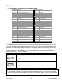
Explanation of commonly used Abbreviations................................................................................................... 90
Password Settings: ........................................................................................................................................... 90
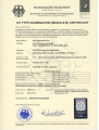
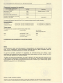
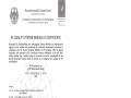
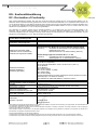
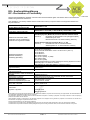
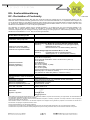
Approvals ...........................................................................................................................................................91
User Manual
3
Y1-03-0203 Rev.L
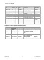
History of Changes
Date
2002-12-04
Version
1.0
2003-03-18
1.0
2003-03-27
1.0
2003-03-31
1.0
2003-06-30
2004-06-03
1.0.1
1.0.2
2004-07-30
1.0.3
2005-07-30
1.0.4
2005-11-21
2006-05-23
2006-11-06
2009-07-28
1.0.5
1.0.6
1.0.7
1.0.8
Rev. Status
A
Released
B
Released
C
D
Comments
Latest release amendments
Updated EC-Conformity
Document inserted.
B553 picture update
New front cover.
Insertion of Wheelmark
Certificate
Corrections
Corrections, new pictures
Graphical User Interface,
new Sensor configuration
Released
Released
E
F
G
H
I
J
K
L
Released
Released
Released
Released
Editorial work
Released
Released
Released
Released
Position pinning
Editorial work
Updated AIS Menu‟s
ITU-R M.1371-3 Updates
Responsible
A. Lesch
C. Moore
F. Gruber
C. Moore
B. Werner
B. Werner
Team
B. Werner,
A. Lesch
A. Lesch
M.D‟Arcangelo
M.D‟Arcangelo
B. Werner
This Manual is valid for following AIS software Version:
Date
AIS software
Version
Status
Comments
Responsible
2009-04-12
2.0.S105.X408
Test
Test version for Approval
tests
A. Lesch
2009-07-28
2.0.S105.X714
Released
New GPS Module. New
way to store ship
dimensions.
A. Lesch
User Manual
4
Y1-03-0203 Rev.L
1 Starting the NAUTICAST
1.1
Initial Set Up of the NAUTICAST for operation
ATTENTION: IMO REGULATIONS MANDATE THAT YOU ENTER THIS INFORMATION.
After installing the antennas and hardware the following User, Voyage related and Ship Settings
data needs to be entered. Upon Start-up (Applying power) enter the following information.
a) Enter MMSI Number - See section 1.2 on entering information.
During the initial boot or after “factory settings” the user is asked to enter a valid MMSI
number. As long as this is not done, the system does not transmit. This appears as Alarm-ID
56 with the text “AIS: ENTER MMSI NUMBER”.
LAT: N/A
LON: N/A
IntN/A:
SOG: N/A
COG: N/A
STOP
00/00/00
24:60:60
! 7A 1T
++++++++++++++++++++++++++++++++++++++++
Time 24:60 00/00
[!] ALARM ID:56
AIS: ENTER MMSI NUMBER
Please press OK to enter MMSI number!
Tx temporary suppressed
++++++++++++++++++++++++++++++++++++++++
---------------------------------------|
OK
|
|
|
b) Enter IMO Number - See section 1.2 on Entering information.
c) Ship Settings Data - After initial entry of the Ship Settings Data any changes in the
information below should be edited accordingly. See section 1.3 on entering information.
Enter Call Sign
Enter Ships Name
Enter Length of Ship
Enter Beam of Ship
Enter Internal GPS antenna Position
Enter External GPS Antenna Position (If applicable).
Enter Ship Type
d) Voyage related Data – After initial entry of the Voyage related Data any changes in the
information below should be edited accordingly.
See paragraph 1.4 above on entering information.
Enter Cargo Type
Enter Draught
Enter Destination
Enter ETA
Enter Navigation Status.
e) Password – Service and User passwords see section 1.5 and Appendix 7.2
User Manual
5
Y1-03-0203 Rev.L
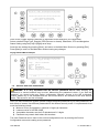
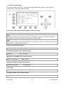
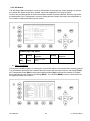
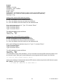
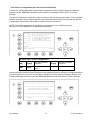
1.2
Entering the MMSI and IMO Numbers
Select from the Main Menu “Service Configuration” Number 6. Menu is SERVICE password
protected (Please see Appendix 7.2 for password information). Enter Service Password and use the
up and down arrows on keypad to select “Change MMSI / IMO” than press M5 “Select” or “by
pressing number 3 on the keypad.
Input your MMSI and IMO number and press Save to store data. Unit will reboot itself after pressing
Save. Continue to 4.2 after reboot, if no IMO number is available use the value 0 (Zero).
N 1o19' E 0o13' |1>0.01|2>1.30|3>1.80nm
|---------------------------------| Menu
-----| |
| +- 1. Messages
View | +- 2. AIS Status
| +- 3. Voyage Settings
-----| +- 4. Ship Settings
| +- 5. Transponder Configuration
Msg. | +- 6. Service Configuration
| +- 7. Display Settings
-----| +- 8. Graphical Display Settings
|
Displ|
---------------------------------------NUM |Select->|
|
<-Back
Service Configuration Menu Example:
N 1o21' E 0o14' |1>0.01|2>1.30|3>1.80nm
|---------------------------------| 6. Service Configuration
-----| |
| +- 1. Change Service Password
View | +- 2. User Password Settings
| +- 3. Change MMSI / IMO
-----| +- 4. Restore Factory Settings
|
Msg. |
|
-----|
|
Displ|
---------------------------------------NUM| Select->|
|
|<-Back
Note: MMSI and IMO Data input are limited to 9 characters.
N 1o21' E 0o14' |1> N/A|2>0.00|3>0.10nm
********** Change MMSI / IMO ***********
MMSI
:1193046
IMO No.:303174162
---------------------------------------NUM| Save |
|
| Back
User Manual
6
Y1-03-0203 Rev.L
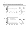
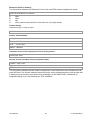
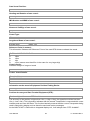
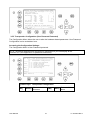
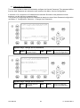
1.3
Entering Ship Settings
Select from the Main Menu “Ship Settings” Menu is USER password protected (Please see
Appendix 7.2 for password information).Enter Password and use the up and down arrows to edit
Ship Settings then press Enter or the numeric reference on the keypad to select and edit.
Save after editing.
Main Menu Example:
N 1o23' E 0o16' |1>0.01|2>1.30|3>1.80nm
|---------------------------------| Menu
-----| |
| +- 1. Messages
View | +- 2. AIS Status
| +- 3. Voyage Settings
-----| +- 4. Ship Settings
| +- 5. Transponder Configuration
Msg. | +- 6. Service Configuration
| +- 7. Display Settings
-----| +- 8. Graphical Display Settings
|
Displ|
---------------------------------------NUM |Select->|
|
<-Back
Select Ship Settings and press M5 [Enter]. Enter User Password and Continue.
Ship Settings Menu Example:
N48^12' E 16^26' |1> N/A|2> N/A|3> N/Anm
************ Ship Settings *************
Call Sign:OEZ1234
/\ +
ShipName :SOLAS 55
/
\|
Ref.Points ext
int
|
|
A: 200m
220m
|
A
B:
20m
N/A
|
|
C:
10m
10m
|
+--|
D:
33m
33m
|
| B
Len (A+B): 220m
220m
|
| |
Beam(C+D):
43m
43m
+-C-+D-+
Ship Type:<Cargo ship>
>>> DATA OK. PRESS M5 TO SAVE DATA <<<
---------------------------------------| Save |
|
| Back
Select and enter Call Sign.
Select and enter Ship Name.
Enter external GPS Antenna Position
Enter internal GPS Antenna Position
Select and enter a default ShipType with the [Left] & [Right] arrows.
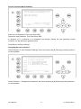
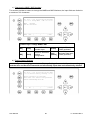
Setting the Internal and External GPS Antenna Position.
Note: It is critical for the proper orientation of your ship to other AIS users to enter this data
accurately.
Example: Length of ship = 220m and Beam = 43m.
User Manual
7
Y1-03-0203 Rev.L
GPS ANTENNA location on ship (is x in above Menu example) is located 200 meters from bow (A)
and 33 Meters from Starboard side (D).
Note: When only using internal GPS antenna it is ok to have default values for external position
since they are not used.
Ref.Points ext (Position of the external GPS antenna)
A = 200m the distance from bow (front) to the antenna.
B= 20m the distance from the antenna to the stern (rear)
C = 10m the distance from the port (left) side to the antenna
D = 33m the distance from the antenna to the starboard (right) side
Enter Ref.Point int (location of the internal GPS antenna) in the same way.
A = 220m the distance from bow (front) to the antenna.
B= 0m the distance from the antenna to the stern (rear)
C = 10m the distance from the port (left) side to the antenna
D = 33m the distance from the antenna to the starboard (right) side
Your reference points must match the entered ship dimensions. Length of ship = 220m and Beam =
43m. For incorrect dimension the AIS shows:
>>> ext/int ship len/beam don't match
After correct settings of the reference points and dimensions you can press M5 - [Save]. to save
your settings:
>>> DATA OK. PRESS M5 TO SAVE DATA <<<
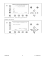
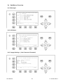
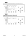
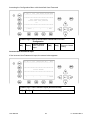
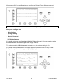
1.4
Entering Voyage Related Data
Select from the Main Menu “Voyage Settings” Menu is USER password protected (Please see
Appendix 7.2 for password information). Enter Password and use the up and down arrows to edit
Voyage Related data then press Enter or the numeric reference on the keypad to select and edit.
Save after editing.
Main Menu Example:
N 1o20' E 0o13' |1> N/A|2>0.00|3>0.10nm
|---------------------------------| Menu
-----| |
| +- 1. Messages
View | +- 2. AIS Status
| +- 3. Voyage Settings
-----| +- 4. Ship Settings
| +- 5. Transponder Configuration
Msg. | +- 6. Service Configuration
| +- 7. Display Settings
-----| +- 8. Graphical Display Settings
|
Displ|
---------------------------------------NUM |Select->|
|
<-Back
Password inquiry Example: The password query field appears. Input password and press M5 [Enter].
User Manual
8
Y1-03-0203 Rev.L
N 1o31' E 0o24' |1>0.01|2>1.30|3>1.80nm
---------------------------------------++++++++++++++++++++++++++++++++++++++++
User password protected!
Please enter user password:
++++++++++++++++++++++++++++++++++++++++
---------------------------------------| Enter |
|
| Exit
Scroll to the Voyage Setting Fields with up and down arrows and input your vessel data.
Select a default Cargo Type, Draught, POB (Persons on board), Destination, ETA and Navigation
Status Setting using the [Left] & [Right] arrow keys.
Save the new settings by pressing [Save], and return to the Main Menu Screen by pressing [Exit].
Press [Back] to return to the Main Menu without saving any changes.
Voyage Related Menu Example:
N 1o18' E 0o12' |1>0.01|2>1.30|3>1.80nm
*********** Voyage Settings ************
Cargo
:<N/A or harmless>
Draught :24.8m
PoB
:1
Dest.
:CASABLANCA
ETA
:10/13 12:31
NavStat.:Engaged in fishing
---------------------------------------| Save |
|
| Back
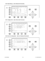
1.5
Service and User Passwords
WARNING: It is very important that the Service password not be lost. Keeping the
password in a second location may be wise. Memorizing the password is best. If you lose this
password, you cannot make any further configuration changes: Access to the AIS is blocked.
Another master key is not available and the unit would have to be returned to the ACR Service
centre. This service is not free of charge.
Once you have entered the system, please change the default password to your own passwords, for
both levels of access. Use different passwords for the different security levels. Your passwords must
meet the following criteria:
Minimum of six (6) characters, maximum of eight (8) characters
Letters must be in UPPER CASE
Acceptable characters are the A-Z alphabet and 0- 9 digits
Password may contain both letters and numbers
The User Password can be reset in the service configuration menu by entering the Service
Configuration menu and creating a new password.
User Manual
9
Y1-03-0203 Rev.L
Changing the Service Password
Select “Service Configuration” from the Main Menu with the cursor button [Up] & [Down] or press
Number 6 on the keyboard.
The password query field appears. Input default Service Password and press M5 [Enter].
N48^12' E 16^26' |1> N/A|2> N/A|3>
N/An
-------------------------------------+++++++++++++++++++++++++++++++++++++++
Service password protected!
Please enter service password:
+++++++++++++++++++++++++++++++++++++++
--------------------------------------| Enter |
|
| Exit
Select Submenu 1 “Change Service Password” with cursor button [Up] & [Down] by pressing
Number 1 on the keyboard.
Service Menu Example:
N48^12' E 16^26' |1> N/A|2> N/A|3> N/Anm
|---------------------------------| 6. Service Configuration
-----| |
| +- 1. Change Service Password
View | +- 2. User Password Settings
| +- 3. Change MMSI / IMO
-----| +- 4. Restore Factory Settings
|
Msg. |
|
-----|
|
Displ|
---------------------------------------NUM|Select->|
|
|<-Back
User Manual
10
Y1-03-0203 Rev.L
Service Password Menu Example:
N48^12' E 16^26' |1> N/A|2> N/A|3> N/An
******* Change Service Password *******
Enter new password :
Repeat new password:
{Length: 6..8 characters
--------------------------------------| Enter |
|
| Back
Enter the new Password: Then push Enter (M5).
Repeat the new Password: Then Push Enter (M5).
A minimum of 6, a maximum of 8 characters are allowed. Should the new password include
numbers, use the shift key to generate them.
Press Save to store the change.
Changing the User Password
Select Submenu 2 “User Password Settings” with cursor button [Up] & [Down] by pressing number 2
on the keyboard.
N48^12' E 16^26' |1> N/A|2> N/A|3> N/Anm
|---------------------------------| 6. Service Configuration
-----| |
| +- 1. Change Service Password
View | +- 2. User Password Settings
| +- 3. Change MMSI / IMO
-----| +- 4. Restore Factory Settings
|
Msg. |
|
-----|
|
Displ|
---------------------------------------NUM|Select->|
|
|<-Back
Select Submenu 1 “Change User Password” with cursor button [Up] & [Down] by pressing Number 1
on the keyboard.
User Manual
11
Y1-03-0203 Rev.L
N48^12' E 16^26' |1> N/A|2> N/A|3> N/Anm
|---------------------------------| 6-2. User Password Settings
-----| |
| +- 1. Change User Password
View | +- 2. Change Password Protection
|
-----|
|
Msg. |
|
-----|
|
Displ|
---------------------------------------NUM|Select->|
|
|<-Back
Enter the new Password. A minimum of 6, a maximum of 8 characters are allowed. Should the new
password include numbers, use the shift key to generate them.
Repeat the new Password.
N48^12' E 16^26' |1> N/A|2> N/A|3> N/A
********* Change User Password *******
Enter new password :
Repeat new password:
{Length: 6..8 character
-------------------------------------| Enter |
|
| Back
Press Save to store the changes.
User Manual
12
Y1-03-0203 Rev.L
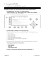
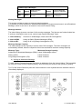
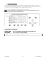
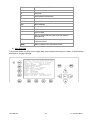
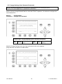
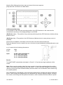
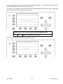
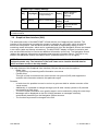
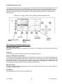
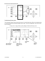
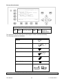
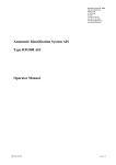
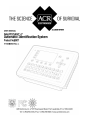
2 NAUTICAST User Interface
Display
Safety Keys
Soft Keys [M1] – [M8]
Navigation Screen
Header (max. 3 lines)
_________________
Navigation Screen or
MENU
Structure
(Content 13 lines)
Keyboard
Enter Key
User Manual
13
Cursor
Cross
Y1-03-0203 Rev.L
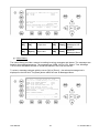
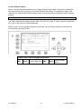
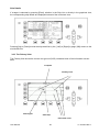
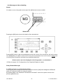
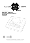
2.1
NAUTICAST Keyboard
The NAUTICAST is fitted with a full alphanumeric keyboard, with the following functions:
By pressing any key on the keyboard the letters are addressed.
Number symbols and special characters are addressed by holding down the
shift [] key and simultaneously pressing the chosen key.
The characters ($; %; &; /; (; ); <;
and pressing the chosen key.
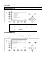
2.2
o
; \ ; [; ]; ) can be reached by holding down the Function [Fn] key
Explanation of the “Cursor Cross”
The Cursor Cross allows navigation within the current screen
[Up] [Down] [Left] [Right].
In addition to the actually displayed [Enter] button, the center of
the cursor cross always has the Enter functionality.
2.3
Explanation of the Num-Locked and [NUM] Functions
The NUM-Locked function is enabled after pressing the Function [Fn] Key and the Shift [] Key.
It is possible to disable the Num-Lock Function by pressing the Shift [] Key.
Tip: The NAUTICAST automatically changes the keys “Q” through to “P” to numerical input when the
current application requires numbers, rather than letters to be input. This feature is enabled when
[NUM] appears on the bottom left hand side of the screen.
User Manual
14
Y1-03-0203 Rev.L
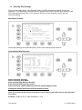
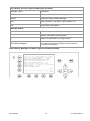
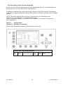
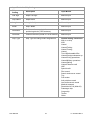
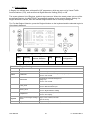
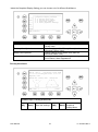
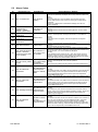
2.4
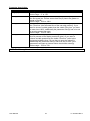
Explanation of the Soft Keys
The Soft Keys are divided into vertical static keys [M1-M4] and horizontal dynamic keys [M5-M8],
which differ in function according to the current application.
Soft Key Definition
filter option on AIS targets in graphical view
FA (hides received Class A targets)
FB (hides received Class B targets)
[M1]
Display Modes
[M2]
This Soft Key allows toggling between the different Display Modes.
Safety Message
[M3]:
This Soft Key allows direct Message Writing. Either broadcast or addressed messages
can be sent in this mode. Pending alarms could be accessed by this Soft Key
[M4]:
Display Settings - Brightness and Contrast Regulator
This Soft Key allows the Display Settings to be changed between Daytime,
and Nighttime Modes.
[Menu]:
Go to Main Menu or return to the Navigation View Screen.
[M5] – [M8]:
These Soft Keys are described in individual screens
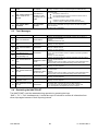
2.5
Safety Keys
The NAUTICAST is fitted with Safety Keys, which allow the user to automatically send urgent
messages without the necessity of navigating the Menus.
[MOB]
The MOB Button sends out precise position of an MOB incident to Addressed
Vessels, therefore allowing the message to be sent to a vessel closest to
accident location.
[SRM]
The SRM Button sends out emergency Broadcast Safety Related Messages to
all ships in the Vessel Listing.
Note: For detailed description of the Safety Functions see Chapter 4.
User Manual
15
Y1-03-0203 Rev.L
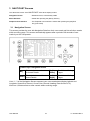
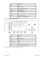
3 NAUTICAST Screens
The advanced version of the NAUTICAST offers three display modes:
Navigation Screen
- Standard screen, automatically visible
Menu Structure
- Visible after pressing the [Menu] Soft Key
Graphical User Interface
- The Graphical User Interface is visible after pressing the [M2] Soft
Key (new mode)
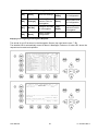
3.1
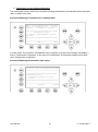
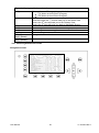
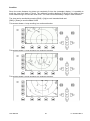
Navigation Screen
This screen provides the user with Navigation Data from their own vessel and lists all other vessels
within receiving range. This screen automatically appears after a period of 60 seconds of user
inactivity on the Transponder.
LAT:N 1°27.845'ExtSOG:34.6kn 05/26/06
LON:E 0°21.289'ExtCOG:173.0°
10:52:26
IntGPS: 3D A/ ExtHDT:222° Reg6 ! 3A 2T
001/021..ShipName....RNG.BRG..SOG..COG..
DOREEN
[Cl-A] N/A 120 22.2 301.5
FINE EAGLE
[Cl-A] 0.00 N/A 13.1 359.9
SYLVAEPSILON [Cl-A] 0.10 23 32.1 203.2
ESSOTOKYO
[Cl-A] 0.43 99 10.0 120.3
KATHARGO
[Cl-B] 0.59 342 21.2 50.0
SANEI
[Cl-A] 0.80 272 32.1 270.1
KATOO
[Cl-A] 1.00 321 21.2 200.8
ID=002319999_[Base] 1.34 277 0.0
0.0
MINILOG
[Cl-A] 1.96 201 21.7 102.2
ALIBRAHIMYA [Cl-A] 2.66 340 22.1 30.3
EWALD M
[Cl-A] 2.75 121 N/A N/A
ID=231919191 [SAR ] 3.36 66 24.1
2.9>
Dynamic Keys: Navigation Screen
[M5]
Select desired vessel
for Vessel Details
[Up] /
[Down]
Scroll Vessel Listing
Pages
[Enter]
Select desired vessel for
Vessel Details
[Left] /
[Right]
Scroll Vessel Listing
Pages
Lines 1 – 3 of the Navigation Screen represent your own vessels data (display Latitude and
Longitude, Speed Over Ground, Course Over Ground, Heading, Date and the UTC).
After line 4, all data refers to other vessels within receiving range.
User Manual
16
Y1-03-0203 Rev.L
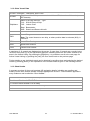
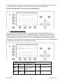
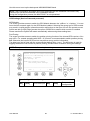
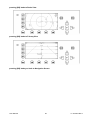
3.1.1 Own Vessel Data
LAT:N
LON:E
1°27.845'ExtSOG:34.6kn
0°21.289'ExtCOG:173.0°
05/26/06
10:52:26
LAT:
Latitude
LON:
Longitude
Date:
The actual UTC - date (MM.DD.YY) and time (hh.mm.ss) are displayed on the top
right hand corner of this view.
IntGPS: 3D
IntGPS
A/
ExtHDT:222° Reg6
Indicates normal or differential mode of GPS position.
2D or 3D: Indicates the precision of the GPS result.
Indicates the used position source:
intGPS.
= internal GNSS receiver
extGPS
= external GNSS receiver (sensors)
A/B: (A or B) Indicates the last transmitting channel in use.
ExtHDT
True Heading
Reg:
Indicates the actual region of own vessel‟s position. If no region number is displayed,
then the vessel is traveling on high sea and is outside a predefined region.
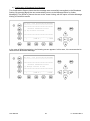
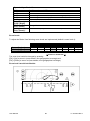
Message (SRM) Indication
LAT:N
1o27.845'ExtSOG:34.6kn
*3S
Queued safety related messages, e.g. *3S are displayed in the date field (instead of the date) – in
the above example 3 Safety Related (3S) Messages are queued, and await viewing and handling
(acknowledgement or reply) in the Message Inbox History.
Alarm (ALR) and Text (TXT) Indication
IntGPS: 3D
/B
Reg6 ! 3A 2T
Queued alarms or messages, e.g. ! 3A 2T are displayed in the 3rd line – in the above example
3 (3A) Alarms and 2 (2T) Text Messages are in queue, and await viewing and handling
(acknowledgement and reaction).
User Manual
17
Y1-03-0203 Rev.L
3.1.2 Other Vessel Data
001/021..SHIPNAME....RNG.BRG..SOG..COG..
001/021
(E.g: Vessel 01 of 021) current or selected Vessel/ Total number of Vessels (max.
256 Vessels)
ShipName:
Name of the Ship and AIS – Type:
Cl-A: SOLAS Class-A Ship
Cl-B: Leisure Craft
Base: Base station
SAR : Search and Rescue Aircraft
RNG
Vessel Range
Note: The vessel closest to own ship, or where position data is unknown (N/A), is
listed first.
BRG
Vessel True Bearing
SOG
Speed Over Ground
COG
Course Over Ground
A maximum of 12 vessels are displayed on the screen. If more than 12 vessels are currently being
received, the symbol [>] on the right bottom appears, indicating that there are further vessels to be
seen in the Vessel Listing. By pressing the [Right] key, it is possible to scroll to the next page for
further Vessel Listing, by pressing the [Left], the user scrolls back to the previous page.
Further details on any individual vessel can be obtained by scrolling down and selecting the desired
vessel by pressing [Enter]. A full explanation of the Vessel Details is given in the following section.
3.1.3 Short Header
A constant overview of the most important AIS navigation details, including own position and
distance of the three closest vessels is always displayed the first line. This information appears in
every Submenu and is called the “Short Header”.
N 1o21 E
0o14' |1>0.10|2>1.30|3>1.80nm
Own Vessel Position: N 1o21' E 0o14'
1> Closest vessel situated 0.10 nm away
2> Second closest vessel situated 1.30nm away
3> Third closest vessel situated 1.80nm away
User Manual
18
Y1-03-0203 Rev.L
3.1.4 Other Vessel Details
This screen shows the Dynamic, Voyage and Vessel Related Data, which is currently being
transmitted by a previously selected vessel.
N 1o21' E 0o14' |1>0,10|2>1.30|3>1.80nm
Time 2:07 -----------------POS:001/021
LAT
: S 74o 50.231' LON :W o 9o 34.192'
Heading :77o
ROT :-0.2 /min l
IMO No. :90733283
MMSI:5004
ShipName:DOREEN
CS:DORET6W
ShipType:Passenger ship
Length :310m
Beam:73m
RefPoint:A190 B120 C10 D>=63m
Cargo
:N/A or harmless
Draught :3.3m
Dest.
:HAWAI
ETA
:10/15 12:31
NavStat.:Moored
EPFDType:GPS
PosAcc :High<10m
DTE :Available
Current Time and Selected Vessel Number in Vessel Listing:
Time 2:07 ---------------- POS: 0001/0021
Time:
The period of time which has elapsed since the last update is shown in minutes and seconds.
The update rate differs according to the respective vessels speed.
POS:
Indicates the number of the selected vessel (e.g. vessel 02 of 21) from the Vessel Listing and the
total number of vessels being received.
Position of the selected vessel:
LAT : S74°50.231'
LON : W 9o 34.192'
Heading and Rotation of the selected vessel:
Heading :77o
ROT :-0.2o/min l
IMO-Number and MMSI of the selected vessel:
IMO No. : 90733283
MMSI: 5004
Name and CallSign of the selected vessel:
ShipName:DOREEN
CS:DORET6W
Vessel Type
Passenger ship
Length and Beam of the selected vessel:
Length:310m
User Manual
Beam:73m
19
Y1-03-0203 Rev.L
Reference Point (in meters):
This information indicates the Reference Point of the used GPS Antenna onboard the vessel.
RefPoint:A190 B120 C10 D<63m
A:
B:
C:
D:
190m
120m
10m
<63m (means more than 63m in the case of a very large vessel)
Vessels Cargo:
Indicates the type of cargo on board.
N/A or harmless
Further Vessel Details:
Draught : 3.3m
Dest
: HAWAII
ETA
: 10/15 12:31
NavSt : Moored
Information on the vessel’s Equipment Position Finding Device:
EPFDType: GPS
Position Accuracy and Data Terminal Equipment (DTE):
PosAcc :High <10m
DTE :Available
This information indicates that the vessel‟s transponder is connected with a user interface and can
show AIS Data. This function basically ensures that the current transponder being used is fitted with
a display and can therefore send and receive messages. As the NAUTICAST is fitted with an
integrated display unit, it will always show “DTE: Available”.
User Manual
20
Y1-03-0203 Rev.L
3.2
Menu Structure
To call up the Main Menu, press the [Menu] button once, and all Submenus are displayed. The
cursor position indicates the selected submenu.
Menu navigation is achieved by pressing the [Up] or [Down] keys to select, and then by pressing
[Enter] to confirm the desired Submenu selection.
To escape from any Submenu and returning to the Navigation Screen, press the [M2] button at any
time.
The own vessel‟s current Navigation Information is continuously displayed on the first line. It
contains the own position and the first three vessels, which are located within closest range of the
own ship.
Tip: Fast Menu Selection is achieved by simply pressing the desired Submenu Number on the
keyboard.
3.3
Main Menu
N 1o46' E 0o39' |1>0.10|2>1.30|3>1.80nm
|---------------------------------| Menu
-----| |
| +- 1. Messages
View | +- 2. AIS Status
| +- 3. Voyage Settings
-----| +- 4. Ship Settings
| +- 5. Transponder Configuration
Msg. | +- 6. Service Configuration
| +- 7. Display Settings
-----| +- 8. Graphical Display Settings
|
Displ|
---------------------------------------NUM |Select->|
|
<-Back
Dynamic Keys: Main Menu Screen
[Enter]
or
[Right]
[M5]
[Select]
Select chosen
Submenu
[M8]
[Back]
Return to Navigation [Up] /
[Down]
Screen
Confirm Submenu
Selection
Navigate Submenu
for selection
Note: The Navigation Screen automatically appears after some seconds of user inactivity on the
Transponder, or immediately by pressing the [Menu] button in the Main Menu.
User Manual
21
Y1-03-0203 Rev.L
3.4
Sub-Menus Overview
3.4.1 Messages
N 1o19' E 0o12' |1>0.10|2>1.30|3>1.80nm
| 1. Messages
-----| |
| +- 1. Write Addressed SRM
View | +- 2. Write Broadcast SRM
| +- 3. Lock Request
| +- 4. Inbox History
-----| +- 5. Inbox SRM
| +- 6. Inbox LRI
Msg. | +- 7. Inbox Lock Reply
| +- 8. Interrogate IFM
-----|
|
Displ|
---------------------------------------NUM|Select->|
|
| <-Back
3.4.2 AIS Status
N 1o18' E 0o12' |1> N/A|2>0.00|3>0.10nm
|---------------------------------| 2. AIS Status
-----| |
| +- 1. State / Conditions
View | +- 2. Own Ship Data
| +- 3. Own VHF Status
-----| +- 4. Alarm Status
| +- 5. TXT Status
Msg. | +- 6. Version Info
| +- 7. Security Log
-----|
|
Displ|
---------------------------------------NUM|Select->|
|
|<-Back
3.4.3 Voyage Settings – (User Password Protected)
N 1o20' E 0o14' |1>0.10|2>1.30|3>1.80nm
*********** Voyage Settings ************
Cargo
:<N/A or harmless>
Draught :24.8m
PoB
:1
Dest.
:CASABLANCA
ETA
:10/13 12:31
NavStat.: Engaged in fishing
---------------------------------------| Save |
|
| Back
User Manual
22
Y1-03-0203 Rev.L
3.4.4 Ship Settings – (User Password Protected)
N48^12' E 16^26' |1> N/A|2> N/A|3> N/Anm
************ Ship Settings *************
Call Sign:OEZ1234
/\ +
ShipName :SOLAS 55
/
\|
Ref.Points ext
int
|
|
A: 200m
220m
|
A
B:
20m
N/A
|
|
C:
10m
10m
|
+--|
D:
33m
33m
|
| B
Len (A+B): 220m
220m
|
| |
Beam(C+D):
43m
43m
+-C-+D-+
Ship Type:<Cargo ship>
>>> DATA OK. PRESS M5 TO SAVE DATA <<<
---------------------------------------| Save |
|
| Back
3.4.5 Configuration – (User Password Protected)
N 1o21' E 0o14' |1>0.10|2>1.30|3>1.80nm
|---------------------------------| 5. Transponder Configuration
-----| |
| +- 1. Change User Password
View | +- 2. Region Settings
| +- 3. Alarm Settings
-----| +- 4. Interrogation Settings
| +- 5. Sensor Settings
Msg. | +- 6. GPS Settings
|
-----|
|
Displ|
---------------------------------------NUM| Select->|
|
| <-Back
3.4.6 Service Configuration – (Service Password Protected)
N 1o21' E 0o14' |1>0.10|2>1.30|3>1.80nm
|---------------------------------| 6. Service Configuration
-----| |
| +- 1. Change Service Password
View | +- 2. User Password Settings
| +- 3. Change MMSI / IMO
-----| +- 4. Restore Factory Settings
|
Msg. |
|
-----|
|
Displ|
---------------------------------------NUM| Select->|
|
|<-Back
User Manual
23
Y1-03-0203 Rev.L
Display Settings
N 1o21' E 0o15' |1>0.10|2>1.30|3>1.80nm
*********** Display Settings ***********
Mode
|
+-[*] Day
Min
Max
| +---- Brightness:<9> [*********]
| +---- Contrast : 6
[******
]
|
|
+-[ ] Night
Min
Max
+---- Brightness: 3
[***
]
+---- Contrast : 2
[**
]
---------------------------------------NUM|DayNight|
|
| Back
3.4.7 Graphical Display Settings
N 1o46' E 0o39' |1>0.10|2>1.30|3>1.80nm
|---------------------------------| 8 Graphical Display Settings
-----| |
| +- 1. Fairway View Scale
View | +- 2. Fairway View Symbols
| +- 3. Radar View Symbols
-----| +- 4. Other graphical Settings
|
Msg. |
|
-----|
|
Displ|
---------------------------------------NUM |Select->|
|
<-Back
3.5
Sub-Menus Detailed
3.5.1 Messages
N48^12' E 16^26' |1> N/A|2> N/A|3> N/An
|--------------------------------| 1. Messages
-----| |
| +- 1. Write Addressed SRM
View | +- 2. Write Broadcast SRM
| +- 3. Inbox History
-----| +- 4. Inbox SRM
| +- 5. Inbox LRI
Msg. |
|
-----|
|
Displ|
--------------------------------------NUM|Select->|
|
|<-Back
User Manual
24
Y1-03-0203 Rev.L
Dynamic Keys: Messages
[M5]
[Select]
Select chosen
Submenu
[Enter]
Confirm Message
Submenu Selection
[M8]
[Back]
Return to Main Menu [Up] /
[Down]
Screen
Navigate Submenu
for Selection
Writing Messages:
This screen provides a means to write and send messages.
It is possible to select between an Addressed Message to a single selected vessel, and a Broadcast
Message, which is sent out to all vessels in the current Vessel Listing.
Message Inboxes:
The Inbox History gives an overview of all incoming messages. The Inboxes are further divided into
3 sections, allowing the user to see, and act upon specific Message Types.
1.3 Inbox History:
1.4 Inbox SRM:
1.6 Inbox LRI:
Overview of all Messages, Alarms and LRI Interrogations
Listing all Safety Related Messages (SRM)
Listing of all Long Range Interrogations (LRI)
Message Storage Capacity:
The Inbox History has the capacity to store a total of 60 messages. The older messages are
automatically deleted, when the respective Inbox has reached its maximum storage capacity.
Message Type:
Addressed or Broadcast Messages (SRM):
Alarms (ALR):
Long Range Interrogation (LRI):
Maximum Storage Capacity:
Latest 30 Messages stored
Latest 20 stored
Latest 10 stored
a) Writing an Addressed Message
To write a Safety Related Message first select an addressee from the Vessel Listing. This is possible
by using the cursor buttons [Up] and [Down], and confirming the selection with [Enter] or [Select].
Tip: For fast Vessel Selection press the Vessel Number on the keyboard and the selected vessel is
immediately displayed.
N 1o26' E 0o20' |1>0.10|2>1.30|3>1.80nm
************ Write Message *************
..ShipName......Dist..SOG..COG..CallSign
1>DOREEN-------> N/A 22.2 301.5 DORET6W
2>FINE EAGLE--->0.00 13.1 359.9 OEX1538
3>SYLVAEPSILON->0.10 32.1 203.2 ND4RX
4>ESSOTOKYO---->0.43 10.0 120.3 ZA9A
5>OLYMPIAHIGHWA>0.59 21.2 50.0 3FSH4
6>SANEI-------->0.80 32.1 270.1 YJQX9
7>KATOO-------->1.00 21.2 200.8 A4F317
8>OLYMPIA PALAC>1.34 [BASESTAT] 4DSW
9>MINILOG------>1.96 21.7 102.2 FOR6
10>ALIBRAHIMYA->2.66 22.1 30.3 DEZ42
11>TITANIC----->2.75 N/A N/A FSG
>
---------------------------------------NUM| Select |
|
| Back
User Manual
25
Y1-03-0203 Rev.L
Dynamic Keys: Messages
[M5]
[Select]
Write Message to
Selected Vessel
[M8]
[Back]
Return to Messages
Menu
[Enter]
Write Message to
Selected Vessel
b) Using the NAUTICAST Message Editor
After selecting a vessel, the Message Editor is automatically displayed.
Messages containing a maximum of 156 characters are allowed. Longer texts require a second
message. After text input completion, transmission to the selected addressee is facilitated by
pressing the [Send] button. The [<Back] button leads to the Message Editor for writing a second
message to the same addressee. A second activation of the [<Back] button leads to the Vessel
Listing and allows selection of another addressee.
It is possible to select the desired channel by pressing the [<Channel>] buttons.
The default setting for Addressed Messages is (auto) in contrast to Broadcasted Messages, where
the default setting is set at Channels A+B (AIS1 + AIS2).
N 1o20' E 0o13' |1>0.10|2>1.30|3>1.80nm
************ Write Message *************
Addressed SRM
SendTo:5004 (DOREEN)
Text:TEXT INPUT IS POSSIBLE HERE
129
---------------------------------------auto/ A / B /A+B
Channel:
[*]/[ ]/[ ]/[ ]
---------------------------------------| Send |<Channel |Channel> | Back
Dynamic Keys: Addressed Message Editor
User Manual
[M5]
[Send]
Send Message
[M6]
[Channel]
Select Transmission
Channel
[M7]
[Channel]
Select Transmission
Channel
[M8]
[Back]
Return to Vessel
Listing
26
[Enter]
Send Message
Y1-03-0203 Rev.L
c) Confirmation of Sent Addressed Message
The confirmation screen shows the successful message transmission and indicates which channels
(AIS1 or AIS2) were used.
Successful Message Transmission on Channel AIS1:
LAT:N 1oo18.963'ExtSOG:34.6kn 05/21/2006
LON:E 0 12.408'ExtCOG:173.0
09:11:08
Ships:21
/B IntGPS: 3D Region6
++++++++++++++++++++++++++++++++++++++++
Transmission Status
[+] AIS1:OK, acknowledgement received
[-] AIS2:
++++++++++++++++++++++++++++++++++++++++
---------------------------------------|
| Send To |
| <-Back
In some cases, the recipient‟s Transponder may not be able to receive the message immediately –
due to Transponder in-operation. In this case, the confirmation of the send message arrives later,
upon Transponder re-operation.
Successful Message Confirmation (late reply):
N 1°18' E 0°12' |1> N/A|2>0.00|3>0.10nm
---------------------------------------++++++++++++++++++++++++++++++++++++++
Transmission Status
[?] AIS1:Late reception of an ack.
[ ] AIS2:
++++++++++++++++++++++++++++++++++++++++
---------------------------------------|
| Send To |
|<-Back
User Manual
27
Y1-03-0203 Rev.L
It is possible, that the recipient‟s Transponder could not receive the message at all, and in this case
the following screen is displayed. It is then recommended to resend the message.
Unsuccessful Message Confirmation (no acknowledgement)
N 1o19' E 0o12' |1>0.10|2>1.30|3>1.80nm
++++++++++++++++++++++++++++++++++++++++
Transmission Status
[ ] AIS1:
[-] AIS2: Sent, but no acknowledgement
++++++++++++++++++++++++++++++++++++++++
---------------------------------------|
| Send To |
|<-Back
d) Writing a Broadcast Message
Upon selection of Write Broadcast SRM in the Message Menu, the Message Editor appears.
Messages containing a maximum of 161 characters are allowed. Longer texts require a second
message. When the text input has been completed, transmission to all vessels within receiving
range is possible by pressing the [Send] button. The [<Back] button leads to the Message Editor.
It is possible to select the desired channel by pressing the [<Channel>] buttons. The default Settings
for Broadcasted Message Setting is A+B (AIS1 and AIS2).
N 1o18' E 0o12' |1>0.10|2>1.30|3>1.80nm
************ Write Message *************
Broadcast SRM
111
Text:MILITARY EXCERSISE IN AREA, KEEP AW
AY. SHIP MASTER
---------------------------------------auto/ A / B /A+B
Channel:
[ ]/[ ]/[ ]/[*]
---------------------------------------| Send |<Channel |Channel> |
Back
Dynamic Keys: Broadcast Message Editor
User Manual
[M5]
[Send]
[M6] /
[M7]
Select Transmission
[Channel] Channel (A+B is
default)
[M8]
[Back]
Send Message
[Enter]
Send Message
Return to Messages
Menu
28
Y1-03-0203 Rev.L
e) Confirmation of Broadcast Sent Message
This Confirmation Screen shows that the message was successfully transmitted on the Broadcast
Setting. By pressing [Back] the user automatically returns to the Message Editor for further
Messaging. The [SendTo] returns the user to the Vessel Listing, with the option of further Message
Writing to individual vessels.
N 1o19' E 0o13' |1>0.10|2>1.30|3>1.80nm
---------------------------------------++++++++++++++++++++++++++++++++++++++++
Broadcast Transmission Status
[+] OK, broadcast successful
++++++++++++++++++++++++++++++++++++++++
---------------------------------------|
| Send To |
| <-Back
In the case of failed transmission, the following screen appears. In this case, it is recommended to
retransmit the Broadcast Message.
N 1o19' E 0o13' |1>0.10|2>1.30|3>1.80nm
---------------------------------------++++++++++++++++++++++++++++++++++++++++
Broadcast Transmission Status
[-] Message could not be sent
++++++++++++++++++++++++++++++++++++++++
---------------------------------------|
| Send To |
|<-Back
User Manual
29
Y1-03-0203 Rev.L
f)
Long Range Interrogation
Mobile, and shore-based stations have the ability to interrogate vessels and make requests for
information over the “Long Range Interface”. The interrogated vessel can either reply in automatic,
or in manual mode. The interrogation request is displayed in both modes.
The arrival of a Long Range Interrogation Request is indicated by:
1L on the top right hand corner of the Navigation Screen. The LRI automatically arrives in the
Message Inbox LRI and can be handled from there.
LAT:N 1oo20.256'ExtSOG:34.6kn
*
1L
o
LON:E 0 13.700'ExtCOG:173.0
07:44:49
IntGPS: 3D
ExtHDT:222o Reg6 SRM /B
001/021..ShipName....RNG.BRG..SOG..COG..
1>DOREEN-----------> N/A 120 22.2 301.5
2>FINE EAGLE------->0.00 N/A 13.1 359.9
3>SYLVAEPSILON----->0.10 23 32.1 203.2
4>ESSOTOKYO-------->0.43 99 10.0 120.3
5>OLYMPIAHIGHWAY FE>0.59 342 21.2 50.0
6>SANEI------------>0.80 272 32.1 270.1
7>KATOO------------>1.00 321 21.2 200.8
8>OLYMPIA PALACE--->1.34 277 [BASESTAT]
9>MINILOG---------->1.96 201 21.7 102.2
10>ALIBRAHIMYA----->2.66 340 22.1 30.3
11>TITANIC--------->2.75 121 N/A N/A
12>BWRTZ123-------->3.36 66 24.1
2.9>
Handling a Long Range Interrogation (LRI)
Default Settings for LRI Requests:
Automatic Mode:
Manual Mode:
The LRI is automatically dealt with and own vessel data is sent.
The LRI needs to be manually handled.
NOTE: The data which may be interrogated via the Long Range Interface can be configured in Menu
5: Configuration, Submenu 5: Interrogation Settings.
User Manual
30
Y1-03-0203 Rev.L
An LRI has arrived;
The NAUTICAST Settings are configured to Automatic Mode:
N 1o20' E 0o13' |1>0.10|2>1.30| * 1L
************** Inbox LRI ***************
LRI *07:44
5004
07:44 11/28 ------------------ POS:01/01
LRI 5004
(automatic mode)
Please confirm with OK!
---------------------------------------|
OK
|
| Reply | Back >
Dynamic Keys: LRI in the Inbox History (automatic mode)
[M5]
[OK]
Confirms that LRI
has been seen
[M7]
[Reply]
Send Addressed
Message to LRI
sender
[M8]
[Back]
Return to
Message Menu
Upon activation of the [OK] button, the user confirms that he has been notified of a current
Transponder system interrogation. This information is useful, as it prevents unknown interrogation
from taking place when the transponder is set in automatic mode.
Upon pressing the [Reply] button, user returns to the Message Editor from where it is possible to
send an addressed message to the LRI sender.
N 1o20' E 0o13' 1>0.10|2>0.00|3>0.10nm
************** Inbox LRI ***************
LRI 07:44
5004
TEXT TO LRI SENDER CAN BE INPUT HERE
07:44 11/28 ------------------ POS:01/01
LRI 5004
ACK
---------------------------------------|
|
| Reply | Back
An LRI has arrived; the NAUTICAST Settings are configured to Manual Mode:
The LRI therefore needs to be manually handled (accepted or rejected)
User Manual
31
Y1-03-0203 Rev.L
N 1o20' E 0o14' ||1>0.10|2>1.30| *
1L
************** Inbox LRI ***************
LRI *07:49
5004
LRI 07:44
5004
07:49 11/28 ------------------ POS:01/02
LRI 5004
(manual mode)
Please acknowledge with OK/Reject!
---------------------------------------|
OK
| Reject | Reply | Back
Dynamic Keys: LRI in the Inbox History (manual mode)
[M5]
[OK]
Accept LRI‟s
[M7]
Send Addressed
[Reply] Message to LRI
Sender
[M6]
[Reject]
Reject LRI‟s
[M8]
[Back]
Return to
Messages Menu
g) Inbox History
The Inbox History provides a means to reading incoming messages and alarms. The messages are
listed in chronological sequence. The message type (SRM, ALR or LRI), Status, Time, Message
Text Preview and MMSI Number of sender are shown in this overview screen.
To select a message navigate with the cursor [Up] or [Down] – the selected message text is
displayed in the text field. The [Back] button takes the user to Messages Menu.
N 1o19' E 0o13'|1>0.10|2>1.30| *1S1A
************ Inbox History *************
ASRM 13:43 PIRATE ATTACK!
5264
ASRM*13:42 LOST COOK!
5004
ALR 13:40 external EPFS lost 25
ALR!*13:38 general failure
6
ALR! 13:39 no sensor pos in use26
13:43 11/21 ------------------ POS:01/05
AddressedSRM
5264
Text: PIRATE ATTACK!
ACK
---------------------------------------|
|
|
| Back
User Manual
32
Y1-03-0203 Rev.L
Inbox History: Overview of Received Messages and Alarms
Message Types:
Description
ASRM
Addressed Safety Related Message
BSRM
Broadcast Safety Related Message
ALR
Alarms (Details – see Alarm Types chapter 5.2)
LRI
Long Range Interrogation
Message Status:
*
Marks a new, unacknowledged message or alarm
!
Marks a valid alarm requiring action
[]
Marks a revoked alarm (no longer active)
ACK (Acknowledged)
Abbreviation, which is displayed on bottom right hand corner
and signifies that selected message or alarm, has been
previously acknowledged.
Inbox History: Message and Alarm Types and Status Definition:
N 1o19' E 0o13' |1>0.10|2>1.30 * 1S1A
************ Inbox History *************
ASRM 13:43 PIRATE ATTACK!
5264
ASRM*13:42 HIGH WINDS IN AREA! 5004
ALR 13:40 external EPFS lost 25
ALR!*13:38 general failure
6
ALR! 13:39 no sensor pos in use26
13:43 11/21 ------------------ POS:01/05
AddressedSRM
5264
Text: PIRATE ATTACK!
ACK
---------------------------------------|
|
|
| Back
User Manual
33
Y1-03-0203 Rev.L
ASRM 13:43 PIRATE ATTACK!
5264
Addressed Safety Related Message, acknowledged by recipient, arrived at 13:43, with text
“Pirate Attack”, from vessel with MMSI 5264
ASRM*13:42 HIGH WINDS IN AREA! 5004
Addressed Safety Related Message, unacknowledged by recipient, arrived at 13:42, with text
“High winds in area!” from vessel with MMSI number 5004
ALR 13:40 external EPFS lost 25
Alarm, no longer active (revoked) with ID Number 25 (see Alarm Types), revoked at 13:40 with
text “external EPFS lost”
ALR!*13:38 general failure
6
Alarm, new and valid with ID Number 6, not yet revoked at 13:38 with text “general failure”.
ALR! 13:39 no sensor pos in use26
Alarm, old, still valid and requiring attention, with ID Number 2, arrived at 13:39 with text “no
sensor position in use”
13:43 11/21 ------------------ POS:01/05
AddressedSRM
5264
Text: PIRATE ATTACK!
The text of the selected message (in this case Message POS 01/05) is shown in the text field.
ASRM – Reading Incoming Addressed Safety Related Messages:
N 1o26' E 0o20' |1>0.10|2>1.30|3>1.80nm
************** Inbox SRM ***************
ASRM*17:39 CAPTAIN IS LOST
5004
ASRM 16:26 ROUGH SEA!
5022
17:39 11/26 ------------------ POS:01/02
AddressedSRM
5004
Text:CAPTAIN IS LOST
Channel:AIS1
ACK
---------------------------------------|
| Reply |
| Back
User Manual
34
Y1-03-0203 Rev.L
ASRM:
Information
Time
17:39
Date
11/26 (mm.dd)
POS
01/02 (Message 01 of 02)
Message Type
AddressedSRM
Status
* (not acknowledged)
MMSI of Sender
5004
Channel
Incoming AIS Channel
ACK
Message not yet acknowledged
ALR – Reading Incoming Alarms:
N48^12' E 16^26' |1> N/A|2> N/A|3> N/Anm
************ Inbox History *************
TXT! 10:00 AIS: INTERNAL DGNSS 24
ALR 09:59 AIS: NO VALID COG I 30
ALR 09:59 AIS: NO VALID SOG I 29
TXT! 09:59 AIS: INTERNAL SOG C 28
ALR 09:59 AIS: NO SENSOR POSI 26
09:59 03/25 ------------------ POS:02/11
[ ] ALARM ID:30 revoked.
AIS: NO VALID COG INFORMATION
ACK
----------------------------------------
|
| Back
|
|
ALR:
Information
Time
17:36
Date
11/26 (mm.dd)
POS
01/1
Message Type
ALARM
Alarm ID
30
Status
[!] Valid alarm, requiring action
See also chapter 5.1 for more details about Alarms
User Manual
35
Y1-03-0203 Rev.L
3.5.2 AIS Status
The AIS Status Menu provides a variety of information concerning own vessel settings, as well as
the current AIS status of the other vessels, which are displayed in the Vessel Listing.
Version Info provides details of the actual software release currently installed. Security Log traces
the downtimes of the Transponder, to ensure those periods of down time when the transponder is
out of order or lacking electricity can be traced.
N 1o19' E 0o12' |1> N/A|2>0.00|3>0.10nm
|---------------------------------| 2. AIS Status
-----| +- 1. State / Conditions
View | +- 2. Own Ship Data
| +- 3. Own VHF Status
-----| +- 4. Alarm Status
Msg. | +- 5. TXT Status
| +- 6. Version Info
-----| +- 7. Security Log
Displ|
---------------------------------------NUM|Select->|
|
|<-Back
Dynamic Keys: AIS Status
[M5]
[Select]
Confirm Submenu
Selection
[M8]
[Back]
Return to Main
Menu
[Enter]
Confirm Submenu
Selection
a) State / Conditions
This screen provides a means to viewing the current AIS status of all vessels within receiving range.
The information reported is own vessel‟s last AIS contact with the other vessel in the listing (Time),
the Transponder mode (Mod.), the synchronization status (Syn.) and the total number of vessels
being received by each vessel in the listing (RXVe). The vessel‟s (MMSI) number is also shown on
the right hand side of the screen.
N 1o22' E 0o15' |1>0.10|2>1.30|3>1.80nm
********** State / Conditions ***** AIS1
ShipName......Time.Mod.Syn.RXVe..MMSI...
DOREEN
2:07 AU I 1 5004
FINE EAGLE
4:51 AU I 11 5008
SYLVAEPSILON 2:54 AU I 1 5264
ESSOTOKYO
2:11 AU D 2 5776
OLYMPIAHIGHWA 6:44 ?? D 1 354503000
SANEI
5:39 AU I 6 776840000
KATOO
2:58 AU D 3 203375830
OLYMPIA PALAC 6:01 AS D 2 241455470
MINILOG
4:42 AS D 7 234712450
ALIBRAHIMYA
7:40 AS B 3 232834560
TITANIC
0:57 AS I 2 419245790>
---------------------------------------|
|
|
|
Back
User Manual
36
Y1-03-0203 Rev.L
Mod.:
AIS Transmission Mode
AU
Autonomous
AS
Assigned
IN
Interrogation/Polled Mode
??
Unknown
Used Channel
AIS1, AIS2
Syn.:
(UTC source)
D
UTC direct
I
UTC indirect
B
Sync to Base
A
Sync to mobile with the most received stations
(Semaphore)
RXVe:
Total number of all received stations by the
individual vessel.
MMSI:
MMSI number of the individual vessel.
b) Own Ship Data
This screen shows own Ship, and Voyage Data, which was previously input in Menu 3: Ship Settings
and Menu 4: Voyage Settings.
N 1o26' E 0o19' |1>0.10|2>1.30|3>1.80nm
Time 0:08 -----------------------------LAT
:N 1o18.901'LON :E 0oo12.345'
Heading :222o
ROT :+5.4 /min r
IMO No. :9100254
MMSI:257530700
ShipName:MYLADY CS:D11233
ShipType:Pilot vessel
Length :220m
Beam:43m
RefPoint:A190 B30 C20 D23m
Cargo
:N/A or harmless
Draught :24.8m
Dest.
:CASABLANCA
ETA
:10/13 12:31
NavStat.:Engaged in fishing
EPFDType:Integrated navigation system
PosAcc :Low >10m
DTE :Available
User Manual
37
Y1-03-0203 Rev.L
Own Vessel Position:
LAT
: N 1°18.901'
LON : E 0°12.345'
Heading and Rotation of own vessel:
Heading :77o
ROT : +5.4°
IMO-Number and MMSI of own vessel:
IMO No. : 9100254
MMSI: 257530700
Name and CallSign of own vessel:
ShipName: MYLADY
CS: D11233
Vessel Type:
Pilot vessel
Length and Beam of own vessel:
Length:310m
Beam:73m
Reference Point (in meters):
This information indicates the Reference Point of the used GPS Antenna onboard the vessel.
RefPoint:A190 B120 C10 D>63m
A:
190m
B:
120m
C:
10m
D:
>63m (means more than 63m in the case of a very large ship)
Vessels Cargo:
Indicates the type of cargo on board
N/A or harmless
Further Vessel Details:
Draught : 3.3m
Dest : HAWAII
ETA : 10/15 12:31
NavSt : Moored
Information on the vessel’s Equipment Position Finding Device:
EPFDType: GPS
Position Accuracy and Data Terminal Equipment (DTE):
PosAcc :High <10m
DTE :Available
The accuracy of the position is higher than 10 m (= High <10m), the opposite would be less than
10m (= Low >10m). This information indicates that the vessels Transponder is connected with a user
interface and can show AIS Data. This function basically ensures that the current Transponder being
used is fitted with a display and can therefore send and receive messages.
As the NAUTICAST is fitted with an integrated display unit, it will always show “DTE: Available”.
User Manual
38
Y1-03-0203 Rev.L
c) Version Info
This Screen shows the actual Software Release which is being run on the NAUTICAST.
N48^12' E 16^26' |1> N/A|2> N/A|3>0.00nm
************* Version Info *************
##
# #
####
# #
# #
# ###
# #
# ##
#
#
# ###
###
#
#
#
#
###
# #
###
# #
# #
##
# #
####
# #
# #
# # ###
## # #
#### ##
# ##
#
# # ### #
Hardware: AIS Transponder Class A R4 J
Software: 2.0.S105.X309
SW Stamp: Mar 25 2009 09:45:59
Modem HW: Issue J
SeCo: 0
Modem SW: 01.10.10
Battery: OK
---------------------------------------|
|
|
|<-Back
d) Security Log
The Security Log is implemented to show the ”switched off” – times of the transponder.
In standard operation, this Log should not contain any entries.
N 1o27' E 0o20' |1>0.10|2>1.30|3>1.80nm
************* Security Log *************
....StartTime..........EndTime.....Cause
01/15/2001 03:11 - 01/15/2001 04:00 Pow.
---------------------------------------|
|
|
|
<-Back
User Manual
39
Y1-03-0203 Rev.L
3.5.3 Voyage Settings (User Password Protected)
NOTE: The default password from the factory is mentioned on your AIS display at the
protection foil. (see Appendix 0 for password information).!
Before entering Voyage Related Data for initial NAUTICAST operation, it is advised to configure the
User Password in:
Menu 5:
Configuration
Submenu 1: Change User Password
N 1o31' E 0o24' |1>0.10|2>1.30|3>1.80nm
---------------------------------------++++++++++++++++++++++++++++++++++++++++
User password protected!
Please enter user password:
++++++++++++++++++++++++++++++++++++++++
---------------------------------------| Enter |
|
| Exit
Dynamic Keys: Voyage Settings (User Password Protected)
[M5]
[Enter]
Confirm Password
[M8]
Input
[Exit]
Return to Vessel
Listing
After the Voyage Settings have been input and saved, this screen appears.
[Exit] takes the user back to the Main Menu.
N 1o30' E 0o24' |1>0.10|2>1.30|3>1.80nm
----------------------------------------
++++++++++++++++++++++++++++++++++++++++
Data saved.
++++++++++++++++++++++++++++++++++++++++
---------------------------------------|
|
|
| <-Exit
User Manual
40
Y1-03-0203 Rev.L
Voyage Settings Entries
After a new User Password has been set, Voyage Settings may be input. A selection is made with
the cursor buttons [Up] or [Down] to reach the individual input fields. The categories “Cargo” and
“NavStat” are equipped with default settings, which can be selected by pressing the [Left] or [Right]
buttons.
Note: ETA is input in the following format: MMDDHHMM
The Cargo Categories are defined by the IMO (ITU-R M.1371, page 47, table 18) and correspond to
the Type of Ship chosen in the Ship Settings.
Entries, which, do not correctly correspond to the Ship Type and Cargo Category Guidelines are
over-looked by the NAUTICAST.
LAT:N 1o27.915'ExtSOG:34.6kn 05/21/2006
LON:E 0o21.360'ExtCOG:173.0
11:01:06
Ships:21
A/ IntGPS: 3D Region6
*********** Voyage Settings ************
Cargo
:<DG, HS or MP (category A)>
Draught :24.8m
PoB
:1
Dest.
:CASABLANCA
ETA
:10/13 12:31
NavStat.: Engaged in Fishing
---------------------------------------| Save |
|
| Back
Dynamic Keys: Input of Voyage Related Data
[M5]
User Manual
[Save]
Confirm Data Input [M8]
41
[Back]
Return to Main
Menu
Y1-03-0203 Rev.L
Data Input Modes
Voyage Setting
Description
Input Modus
Cargo
Cargo Category
Default Setting <Selection>
N/A or harmless
DG, HS or MP (category A)
DG, HS or MP (category B)
DG, HS or MP (category C)
DG, HS or MP (category D)
Draught
Maximum present static
draught
Manual input
PoB
Number of persons on
board
Manual input
Dest
Destination
Manual input
ETA
Estimated Time of Arrival
(ETA)
Manual input
Navigational Status
Default Setting <Selection>
Under way using engine,
At anchor,
Not under command,
Restricted maneuverability,
Constrained by her draught,
Moored,
Aground,
Engaged in fishing,
Under way sailing,
Undefined
NavSt
After the Ship Settings have been input and saved, this screen appears.
[Exit] takes the user back to the Main Menu.
N 1o30' E 0o24' |1>0.10|2>1.30|3>1.80nm
----------------------------------------
++++++++++++++++++++++++++++++++++++++++
Data saved.
++++++++++++++++++++++++++++++++++++++++
---------------------------------------|
|
|
| <-Exit
User Manual
42
Y1-03-0203 Rev.L
3.5.4 Ship Settings (User Password Protected)
After a new User Password has been set, the Ship Settings may be input. The Ship Settings are
usually only set once, upon NAUTICAST initial operation.
A selection is made with the cursor buttons [Up] or [Down] for input field selection. The category
“ShipType” is equipped with default settings, which can be selected by pressing the [Left] or [Right]
buttons.
NOTE: The default password from the factory is mentioned on your AIS display at the
protection foil. (see Appendix 7.2 for password information).
Before entering Ship Settings for initial NAUTICAST operation, it is advised to configure the
User Password in:
Menu 5:
Configuration
Submenu 1: Change User Password
After the User Password has been set, Ship Settings may be input.
N48^12' E 16^26' |1> N/A|2> N/A|3> N/Anm
************ Ship Settings *************
Call Sign:SO52
/\ +
ShipName :SOLAS 52
/
\|
Ref.Points ext
int
|
|
A: 170m
171m
|
A
B:
30m
29m
|
|
C:
15m
N/A
|
+--|
D:
15m
30m
|
| B
Len (A+B): 200m
200m
|
| |
Beam(C+D):
30m
30m
+-C-+D-+
Ship Type: N/A or no ship
>>> DATA OK. PRESS M5 TO SAVE DATA <<<
---------------------------------------NUM| Save |
|
| Back
| Save |
|
| Back
Dynamic Keys: Input of Ship Settings
[M5]
User Manual
[Save]
Confirm Data Input [M8]
43
[Back]
Return to Main
Menu
Y1-03-0203 Rev.L
Input Modes for Ship Settings
Ships
Setting
Description
Input Modus
Call Sign
Ships Call Sign
Manual input
Ship Name
Ships Name
Manual input
Length
Length of ship
Manual input
Beam
Ship‟s Beam
Manual input
RefPntExt:
Position reference points for external
positioning device (GPS antenna)
Manual input
RefPntInt:
Position reference points for GPS antenna
Manual input
Ship Type
Ship Type according to IMO Regulations:
Default Setting <Selection>
N/A or no ship
WIG
Vessel
Vessel-Fishing
Vessel-Towing
VesselTow>200mbreadth>25m
Vessel-Dredg.underwater op.
Vessel-Diving operations
Vessel-Military operations
Vessel-Sailing
Vessel-Pleasure craft
HSC
Special craft
Pilot vessel
Search and rescue vessel
Tug
Port tender
Anti-pollution vessel
Law enforcement vessel
Medical transport
Resolution No 18 (Mob-83)
Passenger ship
Cargo ship
Tanker
Other
User Manual
44
Y1-03-0203 Rev.L
After the Ship Settings have been input and saved, this screen appears.
[Exit] takes the user back to the Main Menu.
N 1o30' E 0o24' |1>0.10|2>1.30|3>1.80nm
----------------------------------------
++++++++++++++++++++++++++++++++++++++++
Data saved.
++++++++++++++++++++++++++++++++++++++++
---------------------------------------|
|
|
| <-Exit
GPS Antenna Mounting
It is important to input the exact mounting position of the GPS Antenna on the vessel as this
influences the accuracy of the displayed target in an ECDIS.
(Ref.Points ext:) = The position of any external positioning device (GPS Antenna) used as primary
position source.
(Ref.Points int:) = The position of the GPS Antenna (fallback device in case primary source is
disabled).
After antenna installation, the distance from the sides must be measured and input.
Either the distance from the vessel‟s bow (a) or the stern (b) and starboard (d) and backboard (c) are
required.
e.g. A vessel with the following dimensions:
Length:
Beam:
220m
43m
Input:
A: 200 - then press Enter or
B: 20 - then press Enter
C: 10 – then press Enter
D: 33 – then press Enter
Result:
The NAUTICAST automatically calculates A+ B and C + D and shows length and beam of the
vessel.
Note: When receiving position data from large vessels, it should be considered that the position
refers to the antenna mounting point upon the vessel. To ensure accurate navigation, the antenna
reference points (see Other Vessels Details) should be taken into consideration when determining
the vessels position.
Also, the electronic chart display in use should be programmed to consider the antenna reference
points. Traffic images are represented in true distances only when all displayed targets, including
own vessel, are working with AIS position information, which considers Antenna reference points.
User Manual
45
Y1-03-0203 Rev.L
Sample:
Display:
CallSign = D11233
ShipName = M/V TUGELA
Length = 200m
Beam = 30m
RefPointExt = A170 B30 C15 D15m (location of the external GPS antenna)
RefPointInT = A171 B29 C0 D30m (location of the internal GPS antenna)
ShipType = Tug
Setting of the external GPS antenna position:
A = 170m the distance from bow to the antenna
B= 30m the distance from the antenna to the stern
C = 15m the distance from the port side to the antenna
D = 15m the distance from the antenna to the starboard side
Move with Up/down keys to A:. Type 170, actuate “Enter ”
Type 30, actuate “Enter ”
Type 15, actuate “Enter ”
Type 15, actuate “Enter ”
The AIS calculates Length and Beam:
Len (A+B):
200m
Beam(C+D): 30m
Setting of the internal GPS antenna position:
A = 171m the distance from bow to the antenna
B= 29m the distance from the antenna to the stern
C = 0m the distance from the port side to the antenna
D = 30m the distance from the antenna to the starboard side
Move with Left/Right and Up/down keys to A:. Type 171, actuate “Enter ”
Type 29, actuate “Enter ”
Type 0, actuate “Enter ”
Type 30, actuate “Enter ”
The AIS calculates Length and Beam:
Len (A+B):
200m
Beam(C+D): 30m
The calculated Length (A+B) and Beam (C+D) of external and internal GPS antenna position must
be the same value, other your entered distances are wrong and the AIS shows in the last line:
>>> ext/int ship length doesn't match
After correct settings of external and internal GPS antenna reference points the AIS allows to press
M5 - [Save]. to save your settings:
>>> DATA OK. PRESS M5 TO SAVE DATA <<<
User Manual
46
Y1-03-0203 Rev.L
N48^12' E 16^26' |1> N/A|2> N/A|3> N/Anm
************ Ship Settings *************
Call Sign:SO52
/\ +
ShipName :SOLAS 52
/
\|
Ref.Points ext
int
|
|
A: 170m
171m
|
A
B:
30m
29m
|
|
C:
15m
N/A
|
+--|
D:
15m
30m
|
| B
Len (A+B): 200m
200m
|
| |
Beam(C+D):
30m
30m
+-C-+D-+
Ship Type: N/A or no ship
>>> DATA OK. PRESS M5 TO SAVE DATA <<<
---------------------------------------NUM| Save |
|
| Back
| Save
Back
|
|
|
3.5.5 Transponder Configuration (User Password Protected)
The Configuration Menu allows the user to alter the hardware-based parameters. User Password
Configuration is also undertaken here.
Accessing the Configuration Settings:
The Configuration Menu is User Password protected.
NOTE: The default password from the factory is mentioned on your AIS display at the
protection foil. (see Appendix 0 for password information).
N 1o33' E 0o26' |1>01.10|2>1.30| * 1A1L
|---------------------------------| 5. Transponder Configuration
-----| |
| +- 1. Change User Password
View | +- 2. Region Settings
| +- 3. Alarm Settings
-----| +- 4. Interrogation Settings
| +- 5. Sensor Settings
Msg. | +- 6. GPS Settings
|
-----|
|
Displ|
---------------------------------------NUM| Select->|
|
|<-Back
Dynamic Keys: Transponder Configuration
[M5]
User Manual
[Select]
Select desired
Submenu
[M8]
47
[Back]
Return to Main
Menu
Y1-03-0203 Rev.L
Accessing the Configuration Menu with the default User Password
N 1o18' E 0o12' |1>0.10|2>1.30|3>1.80nm
---------------------------------------++++++++++++++++++++++++++++++++++++++++
User password protected!
Please enter user password:
****
++++++++++++++++++++++++++++++++++++++++
---------------------------------------| Enter |
|
| Exit
Dynamic Keys: Input of Default User Password to Access
Configuration
[M5]
[Enter]
Confirm Default
User Password
Input
[M8]
[Exit]
Return to Vessel
Listing
Incorrect User Password Input
If the incorrect User Password is input, the screen below appears.
N 1o34' E 0o27' |1>0.10|2>1.30| * 1A1L
----------------------------------------
++++++++++++++++++++++++++++++++++++++++
Access denied!
++++++++++++++++++++++++++++++++++++++++
---------------------------------------|
|
|
| <-Exit
Dynamic Keys: User Password Input (Access Denied)
[M8]
User Manual
[Exit]
Return to Vessel Listing
48
Y1-03-0203 Rev.L
a) Change User Password (for initial NAUTICAST Operation)
It is strongly recommended to change the default User Password upon initial NAUTICAST operation.
A minimum of 6, a maximum of 8 characters are allowed. Should the new password include
numbers, use the shift key to generate them.
N 1o19' E 0o12' |1>0.10|2>1.30|3>1.80nm
|---------------------------------| 5. Configuration
-----| |
| +- 1. Change User Password
View | +- 2. Region Settings
| +- 3. Alarm Settings
-----| +- 4. Interrogation Settings
| +- 5. Sensor Settings
Msg. |
|
-----|
|
Displ|
---------------------------------------NUM|Select->|
|
|<-Back
N 1o33' E 0o27' |1>0.10|2>1.30| * 1A1L
********* Change User Password *********
Enter new password:
Repeat new password:
*****
*****
{Length: 6..8 characters}
---------------------------------------| Enter |
|
| Back
Dynamic Keys: Initial User Password Setting
[M5]
User Manual
[Enter]
Confirm User
Password Input
[M8]
49
[Back]
Return to Menu
Configuration
Y1-03-0203 Rev.L
This screen appears if the new User Passwords are mismatched - i.e. the New User Password and
the Repeated New User Password are not identical.
In this case, it is possible to re-input both the New and Repeated User Passwords again. [Exit] takes
the user back to the User Password Input Screen.
N 1o19' E 0o13' |1>0.10|2>1.30|3>1.80nm
----------------------------------------
++++++++++++++++++++++++++++++++++++++++
Passwords mismatched!
++++++++++++++++++++++++++++++++++++++++
---------------------------------------|
|
|
|<-Exit
Dynamic Keys: User Password Input (Password Mismatched)
[M8]
[Exit]
Return to Password Input Screen
The new User Password configuration has been saved.
N 1o33' E 0o27' |1>0.10|2>1.30| * 1A1L
----------------------------------------
++++++++++++++++++++++++++++++++++++++++
Data saved.
++++++++++++++++++++++++++++++++++++++++
---------------------------------------|
|
|
| <-Exit
User Manual
50
Y1-03-0203 Rev.L
b) Region Settings
A Region is a defined area, with specific VHF parameters, which are sent out by Vessel Traffic
Service Stations (VTS), and received via Digital Selective Calling (DSC) or AIS.
The screen shows a list of Regions, and their input sources. When the vessel enters into one of the
pre-defined Regions, the NAUTICAST automatically switches to the relevant Region Setting. If a
Region Number is vacant, then the relevant Region Name Slot is currently unoccupied.
Tip: For fast Region Selection, press the Region Number on the keyboard and the selected region is
immediately displayed.
N 1o18' E 0o12' |1>0.10|2>1.30|3>1.80nm
*********** Region Settings ************
..Name....Valid...Source.......DaysOld..
1>Region 1 OK A:AddrChM
2 06:21:59
2>Region 2 OK B:BcastChM
37 09:36:14
3>Region 3
4>Region 4 OK ?
N/A
N/A
5>Region 5 OK M:OpManual
23 11:02:40
6>Region 6 OK C:AIS_ChAs
10 12:39:17
7>Region 7
8>Region 8 OK D:DSC_Ch70
27 05:56:34
9>Region 9 OK C:AIS_ChAs
9 17:08:46
In use:Region 6
---------------------------------------NUM| Select->|
New
|
|<-Back
Dynamic Keys: Region Settings
[M5]
[Select]
Confirm Region
Number Selection
[M6]
[New]
Create New Region
[M8]
[Back]
Return to Menu
Configuration
Overview of Region Settings
Name
Region Number
Number of pre-defined Region
Valid
OK
Status of Region Setting - OK: Stored and Valid
Source
A:AddrChM
A: Addressed Channel Management (Msge. 22)
Source: VTS via AIS
B:BcastChM
B: Broadcast Channel Management
(Msge. 22)
Source: VTS via AIS
C:AIS_ChAs
C: AIS Channel Assignment Sentence
Source: Manual ECDIS Input
D:DSC_Ch70
D: Channel 70 Telecommand
Source: Digital Selective Calling
M:OpManual
M: Operator Manual Input
Source: Via Display
DaysOld
Period of time Region Setting is
stored
Days, hours, minutes, seconds
(dd hh:mm:ss)
In use
Region 6
Region Setting of vessel current operation
User Manual
51
Y1-03-0203 Rev.L
Creating a New Region
Parameters for setting up a new Region can be entered and saved here.
N 1o19' E 0o12' |1>0.10|2>1.30|3>1.80nm
********** Create
New Region ***********
NE LAT(1):N 0oo 0.0000'
+----------1
NE LON(1):E 0o 0.0000'
| +------+ |
SW LAT(2):N 0o 0.0000'
| |
| |
SW LON(2):E 0 0.0000'
>|3|<
| |
TrZone(3): 5nm
| +------+ |
ChannAIS1:2087
2----------+
BandwAIS1: Default
ChannAIS2:2088
BandwAIS2: Default
Tx/RxMode: TxA/TxB,RxA/RxB
VHF Power: High
---------------------------------------| Save |
|
| Back
Dynamic Keys: Initial User Password Setting
[M5]
Confirm Region
Data Input
[Save]
[M8]
[Back]
Return to Region
Listing
Inputting Region Settings: Mode of Latitude and Longitude Input:
Example:
44 Degrees, 13.1234 minutes, North
Input Format:
N 44-13.1234
Input Modes for New Regions
Data Field
Field Description
Input Modus
Additional Information
NE LAT(1)
Latitude N/E corner
Manual Input
Degrees and minutes
NE LON(1) Longitude of N/E corner
Manual Input
Degrees and minutes
SW LAT(2) Latitude of S/W corner
Manual Input
Degrees and minutes
SW LON(2) Longitude of S/W corner
Manual Input
Degrees and minutes
TrZone(3)
<Selection>
Nautical Miles
Manual Input
Channel Number
<Selection>
Default Setting as defined by
the channel number
Manual Input
Channel Number
Transitional Zone Size
ChannAIS1 Primary AIS Channel
BandwAIS1
Bandwidth for Primary AIS
Channel
ChannAIS2 Secondary AIS Channel
BandwAIS2
Bandwidth for Secondary AIS
Channel
<Selection>
Tx/RxMode Channel Modes
<Selection>
VHF Power VHF Power Settings
<Selection>
User Manual
52
Default Setting as defined by
the channel number
Tx : Transmitting Mode
Rx: Receiving Mode
Low =
2 Watt
(Default for Ports)
High = 12,5 Watt (Default for
High Sea Regions)
Y1-03-0203 Rev.L
c) Alarm Settings
This screen allows the user to enable or disable the generation and display of Alarms. Alarms are
displayed in the Alarm Inbox (see Menu 5: Transponder Configuration, Submenu 3: Alarm Settings)
and on the ECDIS screen.
Note:
It is highly recommended to enable the Alarm Function.
N 1o19' E 0o12' |1>0.10|2>1.30|3>1.80nm
************ Alarm Settings ************
on/off
Alarm generation: [*]/[ ]
Note: This setting also affects output
on ECDIS port.
---------------------------------------| Save | Change |
| Back
Dynamic Keys: Alarm Settings
[M5]
[Save]
Save Alarm Settings [M8]
[M6]
[Change]
Configure Alarm
Generation (on/off)
[Back]
Return to Submenu
Configuration
d) Interrogation Settings
This screen allows settings for modes of response to Long Range Interrogation Requests (LRI).
It is possible to set the AIS station to respond automatically or manually to LR Interrogations, and
determine which vessel data may be interrogated. It is further possible to reply to incoming LRI‟s.
Long Range Interrogation Settings:
N 1o19' E 0o13' |1>0.10|2>1.30|3>1.80nm
******** Interrogation Settings ********
on/off
LR-Interrogation: [*]/[ ]
Data for Interrogation:
Name,Call,IMO
[*]
Length,Beam,Type [*]
POS
[*]
SOG
[*]
COG
[*]
auto/manu
[*]/[ ]
Cargo
Draught
PoB
Dest,ETA
Date,Time
[*]
[*]
[*]
[*]
[*]
---------------------------------------| Save | Change | All On | Back
User Manual
53
Y1-03-0203 Rev.L
Dynamic Keys: LR Interrogation Settings
[M5]
[Save]
Save LRI Settings
[Up] /
[Down]
Select Data Field
for Configuration
[M6]
[Change]
Enable or Disable
selected Field for
Interrogation
[Enter]
Select Data Field
for Configuration
[M7]
[All On]
Configure All Data [Left] /
[Right]
for Interrogation
Enable or Disable
selected Field for
Interrogation
[M8]
[Back]
Return to Menu
Configuration
Replying to a Long Range Interrogation Request:
The arrival of an LRI is shown in the Navigation Screen (top right hand corner: * 1L)
The detailed LRI is automatically stored in Menu 1:Messages, Submenu: 6 Inbox LRI, where the
request can be read and replied to.
LAT:N 1oo20.261'ExtSOG:34.6kn
*
1L
o
LON:E 0 13.705'IntCOG:173.0
13:37:34
o
IntGPS: 3D
ExtHDT:222 Reg6
/B
001/021..ShipName....RNG.BRG..SOG..COG..
1>DOREEN-----------> N/A 120 22.2 301.5
2>FINE EAGLE------->0.00 N/A 13.1 359.9
3>SYLVAEPSILON----->0.10 23 32.1 203.2
4>ESSOTOKYO-------->0.43 99 10.0 120.3
5>OLYMPIAHIGHWAY FE>0.59 342 21.2 50.0
6>SANEI------------>0.80 272 32.1 270.1
7>KATOO------------>1.00 321 21.2 200.8
8>OLYMPIA PALACE--->1.34 277 [BASESTAT]
9>MINILOG---------->1.96 201 21.7 102.2
10>ALIBRAHIMYA----->2.66 340 22.1 30.3
11>TITANIC--------->2.75 121 N/A N/A
12>BWRTZ123-------->3.36 66 24.1
2.9>
N 1o19' E 0o13' |1>0.10|2>1.30| *
1L
************** Inbox LRI **************
LRI *19:13
5004
19:13 11/26 ------------------ POS:01/01
LRI 5004
(automatic mode)
Please confirm with OK!
---------------------------------------|
OK
|
|
Reply | Back
User Manual
54
Y1-03-0203 Rev.L
Dynamic Keys: Replying to a LR Interrogation
[M5]
[OK]
[M7]
[Reply]
Notifies User of
current
interrogation
Display
Message Editor
for LRI Reply
[M8]
[Back]
Return to
Vessel Listing
Sensor Settings
The screen provides the means to switch the sensor speeds. It allows the user to change sensor
interfaces from IEC61162-1 to IEC61162-2 settings. The data input fields are fitted with default
values. The [Up], [Down] buttons are used for menu navigation, the [Left] or [Right] buttons for
default data input.
Sensor Software Configuration (Service Password protected)
This is new in software version 2.0.1.x. The NAUTICAST offers the following configuration options:
Set up data speed 4800/9600/38400 baud.
Monitor the connected sensor inputs for each sensor channel.
Verify and edit the Sensor Configuration on the display screen.
Analyze the information received from the connected sensor devices.
Produce an electronic installation report.
Configuration of various NMEA protocols.
N 1o19' E 0o12' |1> N/A|2>0.00|3>0.10nm
*********** Sensor Settings ************
BaudRate Sensor1:< 4800>
CRC: auto
Ignored:$HC---$-----$-----$----$-----$-----$-----$----1>Start Monitor>
BaudRate Sensor2: 4800
CRC: auto
Ignored:$HC---$-----$-----$----$-----$-----$-----$----2>Start Monitor>
BaudRate Sensor3: 38400
CRC: auto
Ignored:$HC---$-----$-----$----$-----$-----$-----$----3>Start Monitor>
---------------------------------------| Save | Default | Analyze | Back
Dynamic Keys: Sensor Settings
User Manual
[M5]
[Save]
Save Data Input
[Up] /
[Down]
Select Data Field
for Configuration
[M6]
[Default]
Restore the
default settings
[Enter]
Select Data Field
for Configuration
[M7]
[Analyce]
Analye you NMEA [Left] /
[Right]
Data streem
[M8]
[Back]
Return to Menu
Configuration
55
Configure Data
Y1-03-0203 Rev.L
Use this menu to set up the data speed 4800/9600/38400 baud.
NOTE: This Configuration should be done from advanced user like installation technicians only.
Therefore you will find more details in the installation manual.
During the configuration process, the NAUTICAST is not operational.
GPS Settings (Service Password protected)
GPS Module:
The screen provides means to switch the GPS Module between the „<µBlox>‟ or „<Jupiter>‟. You can
force the AIS to search again for the GPS Module installed. Selecting the wrong type of GPS module
may result in invalid position information and/or malfunction so that your AIS can not operate correct.
Select and with [Left] & [Right] arrows the option <SEARCH>to search which module is installed
Please mention the system will restart automatically when saving these setting later. .
Pos.Pinning:
The screen provides means to switch the position pinning function of the internal GPS receiver <On>
and <Off>. For vessels operating with SOG < 0,3 knots it is recommended to switch position pinning
Off. Otherwise the internal GPS receiver may deliver wrong position information.
The data input field is fitted with the recommended default value (<on>). The M6 button is used for
toggling between the two modes of position pinning; the M5 button is used for saving the settings.
NOTE: The system will be restarted after saving the settings.
N48^12' E 16^26' |1> N/A|2> N/A|3>0.00nm
************* GPS Settings *************
GPS module : <Jupiter>
Pos. Pinning: On
NOTE: The system will restart
when saving these settings.
---------------------------------------| Save |
|
| Back
Dynamic Keys: Sensor Settings
[M5]
User Manual
[Save]
Save Data Input [M8]
56
[Back]
Return to Menu
Configuration
Y1-03-0203 Rev.L
3.5.6 Service Configuration (Service Password Protected)
The Service Configuration Menu allows initial configuration of the Service Password, Password
Settings (on/off), MMSI/IMO Numbers and the option of resetting the NAUTICAST to Factory
Settings.
The Service Password is required in order to enter the Service Configuration Menu. This is a higher
security level than can be reached with the User Password and therefore ensures that the Service
Configuration is protected, and limited to authorized service personnel.
NOTE: The default password from the factory is mentioned on your AIS display at the
protection foil. (see Appendix 0 for password information).
N 1o23' E 0o17' |1>0.10|2>1.30|3>1.80nm
|---------------------------------| 6. Service Configuration
-----| |
| +- 1. Change Service Password
View | +- 2. User Password Settings
| +- 3. Change MMSI / IMO
-----| +- 4. Restore Factory Settings
|
Msg. |
|
-----|
|
Displ|
---------------------------------------NUM| Select->|
|
|<-Back
Dynamic Keys: Service Configuration
[M5]
[Select]
Confirm Submenu
Selection
[M8]
[Back]
Return to Main
Menu
[Enter]
Confirm Submenu
Selection
After entering the Default Service Password in the password query, the Service Configuration Menu
may be accessed. In this menu it is possible to configure both the Service Password and the User
Password Settings, as well as input the MMSI/IMO Numbers and reset them to Factory Settings.
N 1o24' E 0o17' |1>0.10|2>1.30|3>1.80nm
---------------------------------------++++++++++++++++++++++++++++++++++++++++
Service password protected!
Please enter service password:
++++++++++++++++++++++++++++++++++++++++
---------------------------------------| Enter |
|
| Exit
User Manual
57
Y1-03-0203 Rev.L
a) Change Service Password
This screen provides a means to individually configure the Service Password. This password differs
from the User Password as it allows the user access to the Menu „Service Configuration“.
A minimum of 6, a maximum of 8 characters are allowed. Should the new password include
numbers, use the shift key to generate them.
The process of configuring the Service Password is identical to that of User Password configuration
(see Menu 5: Configuration, Submenu 1: Change User Password).
N 1o25' E 0o18' |1>0.10|2>1.30|3>1.80nm
******* Change Service Password ********
Enter new password :
Repeat new password:
{Length: 4..8 characters}
---------------------------------------| Enter |
|
| Back
Dynamic Keys: Change Service Password
[M5]
[Enter]
Confirm New Service
[M8]
Password Input
[Back]
Return to Submenu
Service Configuration
N 1o27' E 0o20' |1>0.10|2>1.30|3>1.80nm
******* Change Service Password ********
Enter new password :****
Repeat new password:****
{Length: 4..8 characters}
---------------------------------------| Save |
|
| Back
Dynamic Keys: Change Service Password
[M5]
User Manual
[Save]
Save New Service
Password
[M8]
58
[Back]
Return to Submenu
Service Configuration
Y1-03-0203 Rev.L
b) User Password Settings
N 1o24' E 0o18' |1>0.10|2>1.30|3>1.80nm
|---------------------------------| 6-2. User Password Settings
-----| |
| +- 1. Change User Password
View | +- 2. Change Password Protection
|
-----|
|
Msg. |
|
-----|
|
Displ|
---------------------------------------NUM| Select->|
|
|<-Back
Change User Password Protection:
This function allows the user to enable or disable the User Password Query Function. For security
reasons, it is highly recommended to enable User Password Protection in order to avoid
unauthorized Transponder operation.
After the settings have been input and saved, the Data Saved Screen confirms the new
configuration.
N 1o19' E 0o12' |1>0.10|2>1.30|3>1.80nm
****** Change Password Protection ******
on/off
User password protection: [*]/[ ]
Note: It is highly recommended that you
enable user password protection.
---------------------------------------| Save | Change |
| Back
Dynamic Keys: Change User Password Protection
[M5]
[Save]
Save User
Password Setting
[M6]
[Change]
Configure Password [Right] / Configure Password
[Left]
Setting (on/off)
Setting (on/off)
[Back]
Return to Submenu
User Password
Settings
[M8]
User Manual
59
[Enter]
Save User
Password Setting
Y1-03-0203 Rev.L
c) Changing the MMSI / IMO Numbers
This screen provides a means to change the MMSI and IMO Numbers; the input fields are limited to
a maximum of 9 characters.
N 1o19' E 0o13' |1>0.10|2>1.30|3>1.80nm
********** Change MMSI / IMO ***********
MMSI
:1193046
IMO No.:303174162
---------------------------------------NUM| Save |
|
| Back
Dynamic Keys: Change MMSI / IMO
[M5]
[Save]
Save MMSI/IMO
Number Input
[Enter]
Navigate Data Input
Fields (up/down)
[M8]
[Back]
Return to Submenu
Service
Configuration
[Up] /
[Down]
Navigate Data Input
Fields (up/down)
d) Restore Factory Settings
CAUTION: By acknowledging the return to Factory Settings Command, all previous settings,
both the User and Service Passwords and all manually input data are automatically deleted!
N 1o20' E 0o13' |1>0.10|2>1.30|3>1.80nm
******* Restore Factory Settings *******
Really overwrite all settings?
Note: This also affects both passwords.
Please acknowledge with OK!
---------------------------------------|
OK
|
|
|<-Back
User Manual
60
Y1-03-0203 Rev.L
After pressing [OK], the Data Saved Screen confirms the Restore Factory Settings command.
N 1o20' E 0o13' |1>0.10|2>1.30|3>1.80nm
----------------------------------------
++++++++++++++++++++++++++++++++++++++++
Data saved.
++++++++++++++++++++++++++++++++++++++++
---------------------------------------|
|
|
|<- Exit
Note: The NAUTICAST has been restored to the Factory Settings!
Now please configure your:
-
Ship Settings
Voyage Settings
User Password
Service Password
3.5.7 Display Settings
It is possible to choose from Daylight and Nightlight Display Settings; it is further possible to adjust
the Brightness and Contrast Settings for both Display Settings.
The maximum setting for Brightness and Contrast is <9>, the minimum setting is <0>.
It is possible to automatically switch the Display Settings on the NAUTICAST to Day or Night
Settings from any Menu Screen by pressing the [M4] [Displ] button.
N 1o20' E 0o14' |1>0.10|2>1.30|3>1.80nm
*********** Display Settings ***********
Mode
|
+-[*] Day
Min
Max
| +---- Brightness:<9> [*********]
| +---- Contrast : 6
[******
]
|
|
+-[ ] Night
Min
Max
+---- Brightness: 3
[***
]
+---- Contrast : 2
[**
]
---------------------------------------NUM| DayNight|
|
| Back
User Manual
61
Y1-03-0203 Rev.L
Dynamic Keys: Display Settings
[M5]
[DayNight] or Night Settings
[Enter]
Switch between
Day or Night
Settings
[M8]
[Back]
[Up] /
[Down]
Navigate Input
Fields
[Left] /
[Right]
Regulate Modes
(min/max)
Switch between Day
Return to Main Menu
NOTE: The Brightness and Contrast Setting can be directly changed from the keyboard by inputting
the desired value.
3.6
Graphical User Interface (GUI)
The advanced version of the NAUTICAST is fitted with the new Graphical User Interface. The
intention of this interface is to enable the operator to visualize any AIS traffic, which is traveling
around the own position. Fast and direct access to AIS data is supported by display of a list
containing vessel information, which can be reached directly from the Navigation Screen and viewed
in two views (radar and fairway orientations). The NAUTICAST display is limited in resolution and
size and should therefore be used as an additional information source only. The Navigation Screen
(without the graphical information) remains the most relevant information source. The GUI is only
visible in the advanced version of the NAUTICAST (software version 2.0.1.0 or higher).
NOTE: The Automatic Identification System (AIS) provides additional information from AIS
equipped vessels only. The intentions of the new views are to visualize this AIS data for
better and faster access to the ship details.
The main features of this Graphical User Interface (GUI) are the two new view options:
- Radar View
The typical way of presenting traffic information on screens
- Fairway View
This type of view is oriented to the current course over ground (COG) and supports the
operator with information related to this particular region
Remarks
- In both views it is possible to zoom in and out to get more detail or a better overview of the
visual content.
- Additionally, it is possible to change the target (own & other vessel) symbols to fit personal
requirements in both views.
- To receive further information on a specific target it can be selected by using the cursor keys.
- Messages will be displayed on the GUI. Writing answers to messages is done by
automatically transferring to the Navigation Screen structure.
- The function keys remain unchanged in the GUI.
User Manual
62
Y1-03-0203 Rev.L
Dynamic Keys: graphical user interface
[M1]
filter option on AIS targets in graphical view
[M2]
[M3]
[M5]
[M7]
[Menu]
[FN] +
[Up] / [Down]
[Shift]+
[Up] / [Down] /
FA (hides received Class A targets)
FB (hides received Class B targets)
Switch between the views from the Navigation Screen
press the button the 1st time will lead you to the Radar View
press it the 2nd time will lead you to the Fairway View
press it the 3rd time will bring you back to Navigation Screen
Show alarm windows
Acknowledge alarms or safety related messages (SRM)
Acknowledge SRM and Reply
Selects the Main Menu
Changes the Zoom Level
Scrolls the view (only in radar view available)
3.6.1 Switching between the Views
Navigation Screen
LAT:N 1oo27.845'ExtSOG:34.6kn
05/26/2006
o
LON:E 0 21.289'IntCOG:173.0
10:52:26
IntGPS: 3D
ExtHDT:222o Reg6
A/
001/021..ShipName....RNG.BRG..SOG..COG..
1>DOREEN-----------> N/A 120 22.2 301.5
2>FINE EAGLE------->0.00 N/A 13.1 359.9
3>SYLVAEPSILON----->0.10 23 32.1 203.2
4>ESSOTOKYO-------->0.43 99 10.0 120.3
5>OLYMPIAHIGHWAY FE>0.59 342 21.2 50.0
6>SANEI------------>0.80 272 32.1 270.1
7>KATOO------------>1.00 321 21.2 200.8
8>OLYMPIA PALACE--->1.34 277 [BASESTAT]
9>MINILOG---------->1.96 201 21.7 102.2
10>ALIBRAHIMYA----->2.66 340 22.1 30.3
11>TITANIC--------->2.75 121 N/A N/A
12>BWRTZ123-------->3.36 66 24.1
2.9>
User Manual
63
Y1-03-0203 Rev.L
pressing [M2] leads to Radar View
pressing [M2] leads to Fairway View
pressing [M2] leads you back to Navigation Screen
User Manual
64
Y1-03-0203 Rev.L
3.6.2 The Radar View
This screen provides the user with a commonly used way of representing ship objects on an
electronic device. The Radar View is northern orientated, as indicated by the compass on the very
right top of the screen.
Other AIS targets
Own ship position
Distance rings around the own position
The Elements of the Radar View:
Own Ship:
A symbol for the own ship is displayed in the middle of the screen. This can be changed by scrolling
through the window (for detailed description see later chapter) Error! Reference source not
ound..
AIS-Targets:
Other AIS-Targets received within VHF range are displayed as long as they fit in the current zoom
level. They are displayed according to their current heading.
Distance Rings:
The distance rings are marked in nautical miles according to the current zoom level.
Symbol Representation:
There is a choice of personalized symbols for the own ship, as well as symbols for the other AIStargets. (For symbol selection refer to page 67 “Scrolling”).
User Manual
65
Y1-03-0203 Rev.L
Dynamic Keys: Radar View
[M1]
Set filter option on AIS Targets
[M2]
Switch between the views
[M3]
Show alarm window
[M5]
Acknowledge alarms or safety related messages (SRM)
[M7]
Acknowledge SRM and reply
[Menu]
Selects the Main Menu
[Up] / [Down] /
Activate the minimized radar view
[Left] / [Right]
[FN] +
Change the zoom level
[Up] / [Down]
[Shift]+
Scroll the view (only available in radar view)
[Up] / [Down] /
Zoom Levels
To adjust the Radar View following zoom levels are implemented (default is zoom level 4):
Radius
Outer Ring [nm]
Middle Ring [nm]
Inner Ring [nm]
1
0,3
0,2
0,1
2
0,6
0,4
0,2
3
1,5
1
0,5
ZOOM LEVEL
4
5
3
7,5
2
5
1
2,5
6
15
10
5
7
30
20
10
8
45
30
15
zoom in / zoom out
The zoom level could be changed by pressing
[FN] + [Up] to zoom in (more details, less geographical coverage) and
[FN] + [Down] to zoom out (less details, more geographical coverage)
Zoom level 2 would look like this:
User Manual
66
Y1-03-0203 Rev.L
Scrolling
Since the outer distance ring does not completely fit into the (rectangle) display, it is possible to
scroll the view from North or South. The maximum scrolling distance is limited to the radius of the
outer distance ring in the current zoom level. The view can be scrolled by 2 steps in each direction.
The view can be scrolled by pressing [Shift] + [Up] to scroll towards North and
[Shift] + [Down] to scroll towards South
This screen shows a 1 step scrolling in a northern direction.
This screen shows a 1 step scrolling in a southern direction.
This screen shows a 2 step scrolling in a southern direction.
User Manual
67
Y1-03-0203 Rev.L
The Minimized Radar View
The minimized radar view shows a split screen. On the left hand side a Ship List is displayed, on the
right hand side a minimized view of the Radar View is visible. This view will be displayed, if one of
the cursor keys is pressed. The difference between the minimized, and the large view options are
that the minimized view shows the maximum in both North and South direction, since scrolling is
NOT possible.
Radar View [Up] | [Down] | [Left] | [Right] Minimized Radar View
minimized
Radar View
Ship List
[M4] “Message Write”
Button
[M6] Ship List /
Minimized View
Switch
[M8] Exit
Button
The Elements in the Minimized Radar View:
“Message Write” Button:
By pressing the [M4] button, a message can be sent to an AIS target that is currently selected in the
Ship List.
Ship List:
This list shows the same targets as shown in the Navigation Screen.
Ship List / Minimized View Switch:
This switch indicates whether targets can be selected from the Ship List or from the minimized view.
If the arrow above the [M6] points to the left, targets can be selected from the Ship List with the [Up]
and [Down] buttons. If the above arrow points to the right, targets can be selected from the
minimized view with the [Up] or [Down] or [Left] or [Right] buttons. Regardless on which side of the
screen targets are selected, both views correspond to each other.
Minimized View:
This view is the minimized representation of the normal Radar View. Zoom in/out is also possible in
the Minimized Radar View
Exit Button:
The exit button returns the user to the Radar View.
User Manual
68
Y1-03-0203 Rev.L
Ship Details
If a target is selected by pressing [Enter], whether in the Ship List or directly in the graphical view,
the corresponding ship details are displayed instead of the minimized view.
Pressing [Up] or [Down] scrolls the ship detail list by line, [Left] or [Right] by page. [M8] returns to the
minimized view.
3.6.3 The Fairway View
The Fairway View shows the course over ground (COG) orientated view of the Information screen
data.
Compass
Fairway Lines
AIS Targets
Own Ship
Horizontal Lines
User Manual
69
Y1-03-0203 Rev.L
The Elements in the Fairway View:
Compass:
Shows the current COG.
Fairway Lines:
The Fairway Lines are border lines of a virtual fairway oriented on the actual course over ground.
AIS-Targets:
Other AIS targets received via VHF are displayed, if their distance is within the range of the current
zoom level.
Own Ship:
A symbol for the own ship is displayed in the middle of the screen and can not be changed.
Horizontal Lines:
The horizontal lines are the equivalent to the radar views distance rings.
Dynamic Keys: Fairway View
[M1]
Set filter option on AIS targets
[M2]
Switch between the views
[M3]
Show alarm windows
[M5]
Acknowledge alarms or safety related messages (SRM)
[M7]
Acknowledge SRM and reply
[Menu]
Select the Main Menu
[Up] / [Down] /
Activate the minimized radar view
[Left] / [Right]
[FN] +
Change the zoom level
[Up] / [Down]
Zooming
The following zoom levels are implemented for adjusting the Fairway View (default is zoom level 4):
Radius
Outer Ring [nm]
Middle Ring [nm]
Inner Ring [nm]
1
0,3
0,2
0,1
2
0,6
0,4
0,2
3
1,5
1
0,5
ZOOM LEVEL
4
5
3
7,5
2
5
1
2,5
6
15
10
5
7
30
20
10
8
45
30
15
zoom in / zoom out
The zoom level can be changed by pressing
[FN] + [Up] to zoom in (more details, less geographical coverage) and
[FN] + [Down] to zoom out (less details, more geographical coverage)
User Manual
70
Y1-03-0203 Rev.L
Zoom Level 2 would look like this:
The Minimized Fairway View
The minimized Fairway View shows a split screen. On the left hand side a Ship List is displayed and
on the right hand side a minimized Fairway View is seen. This view is displayed, if one of the cursor
keys is pressed.
Fairway View [Up] | [Down] | [Left] | [Right] Minimized Fairway View
Minimized
View
Ship List
[M4] “Message
Write” Button
User Manual
[M6] Ship List /
Minimized View
Switch
71
[M8] Exit
Button
Y1-03-0203 Rev.L
The Elements in the Minimized Fairway View:
“Message Write” Button:
By pressing the [M4] button, a message could be sent to that AIS-Target that is currently selected in
the Ship List.
Ship List:
This list shows the same targets as shown in the Navigation Screen.
Ship List / Minimized View Switch:
This switch indicates whether targets can be selected from the Ship List or from the minimized view.
If the arrow above the [M6] points to the left, targets can be selected from the Ship List with the [Up]
and [Down] buttons. If the arrow above points to the right, targets can be selected from the
minimized view with the [Up] or [Down] or [Left] or [Right] buttons. Regardless on which side of the
screen targets are selected, both views correspond to each other.
Minimized View:
This view is the minimized representation of the normal Radar View. Zoom in/out is also possible in
this view.
Exit button:
The exit button returns the operator to the Radar View.
Zooming is also possible in the Minimized Fairway View
Ship Details
If a target is selected, whether in the Ship List or directly in the graphical view, the corresponding
ship details are displayed instead of the minimized view.
Pressing [Up] or [Down] scrolls the ship detail list by line, [Left] or [Right] by page. [M8] returns to the
minimized view.
User Manual
72
Y1-03-0203 Rev.L
3.6.4 Message and Alarm Handling
Alarms
If an alarm occurs, the symbol to the right of the [M3] button becomes visible.
M3
Alarm Icon
Pressing the [M3] button shows the details of the selected alert.
Pressing [M5] leads to alarm acknowledgement and the closure of the window as well as the alarm
icon disappearing. An alarm could occur at every time so the alarm icon can be seen in every view
(in the big views as well as minimized views and ship details list).
Alarms can be set to be displayed <in the foreground > or <minimized >
Refer to chapter 3.6.5 Configuration of the Graphical Display for details
Safety Related Messages
If a SRM is received, it is displayed immediately.
Pressing [M5] acknowledges the SRM and closes the window. [M6] acknowledges the SRM and
leads you to the text screen for writing an answer.
By pressing [M8] in the “Broadcast Transmission Successful” screen the system returns to the
previous graphical view.
User Manual
73
Y1-03-0203 Rev.L
3.6.5 Configuration of the Graphical Display
General
The configuration of the Graphical Display could be accessed over the entry point 8 of the Main
Menu.
N 1o46' E 0o39' |1>0.10|2>1.30|3>1.80nm
|---------------------------------| Menu
-----| |
| +- 1. Messages
View | +- 2. AIS Status
| +- 3. Voyage Settings
-----| +- 4. Ship Settings
| +- 5. Transponder Configuration
Msg. | +- 6. Service Configuration
| +- 7. Display Settings
-----| +- 8 Graphical Display Settings
|
Displ|
---------------------------------------NUM |Select->|
|
|
<-Back
Dynamic Keys: Main Menu Screen
[Enter]
or
[Right]
[M5]
[Select]
Select chosen
Submenu
[M8]
[Back]
Return to Navigation [Up] /
[Down]
Screen
Confirm Submenu
Selection
Navigate Submenu
for selection
The Configuration Menu allows the user to alter the parameters of the Graphical Display.
Accessing the Configuration Settings:
The Configuration Menu is User Password protected.
N 1o31' E 0o24' |1>0.10|2>1.30|3>1.80nm
---------------------------------------++++++++++++++++++++++++++++++++++++++++
User password protected!
Please enter user password:
++++++++++++++++++++++++++++++++++++++++
---------------------------------------| Enter |
|
| Exit
User Manual
74
Y1-03-0203 Rev.L
Inside the Graphical Display Setting you can choose out of 4 different Sub-Menus.
N 1o46' E 0o39' |1>0.10|2>1.30|3>1.80nm
|---------------------------------| 8 Graphical Display Settings
-----| |
| +- 1. Fairway View Scale
View | +- 2. Fairway View Symbols
| +- 3. Radar View Symbols
-----| +- 4. Other graphical Settings
|
Msg. |
|
-----|
|
Displ|
---------------------------------------NUM |Select->|
|
<-Back
Sub-Menu
Fairway View Scale
Content
Settings of the Geometry and Scale of the
Fairway View
Symbol settings of the Fairway View (also the
minimized Fairway View)
Symbol settings of the Radar View (also the
minimized Radar View)
AIS-target filter settings; enabling / disabling the Auto
Zoom feature; Alarm appearance
Fairway View Symbols
Radar View Symbols
Other Graphical Settings
Fairway View Scale
N53°31 E10° 1
|1>0.69|2>0.77|3>1.08nm
*********** Fairwayview Scale **********
Angle(A): 178°
Dim(B):50%
Dim(C):100%
Dim(D):20%
\ - A - /
+- B -+
+
+
/
\
\ . /
/
\
/ \
/
\
|
|
+ - - C - - +|
|
|
.
|D
+---+
+-----/ \-----+---------------------------------------NUM| Save
|
|
| Back
Dynamic Keys: Fairway View Scale
[M5]
User Manual
[Save]
Save the settings
75
[M8]
Return to
[Back] Graphical
Display Menu
Y1-03-0203 Rev.L
Parameter description:
Parameter
Angle(A)
Dim(B)
Dim(C)
Dim(D)
Description
The angle α defines the visible sector.
Value range: 2° to 178°
The parameter Dim(B) defines the width of the fairway in percent of
the horizontal line. Please ensure that Dim(C) has to be greater or
equal to Dim(B).
Value range: 10% to 100%
The parameter Dim(C) defines the width of the fairway in percent of
the „Zero-line“ (the horizontal line of the own ship position). If you
want to choose a width greater than the visible “Zero-line” you have
to enter here 100%, additionally the parameter Dim(D) has to be set
to a value greater than zero.
Value range: 10% to 100%
The parameter Dim(D) defines the height of the horizontal guidance
lines in percent of the display resolution (pixel). If you want to
choose a width greater than the visible “Zero-line” (refer to the
horizontal guidance lines f´2) you have to enter the value 0%,
additionally the parameter Dim(C) has to be set to 100% (your
parameters will pass an internal value check while entering).
Value range: 10% to 70%
NOTE: The Fairway View is a “non linear View”.
User Manual
76
Y1-03-0203 Rev.L
The following drawing illustrates the parameters from the Fairway View Scale Menu and additionally
presents the transformation process from the Radar View to the Fairway View.
260°
325.0°
30°
DIM(B)
15 nm
10 nm
f1
f2
Horizontal
line
f '2
5 nm
Dim(D)
Zero-line
DIM(C)
S2
S1
S3
325°
N
0°
COG
280°
s
260°
30°
Angle(A)
5
10
15
nm
235°
55°
S6
S4
180°
100°
S5
145°
User Manual
77
Y1-03-0203 Rev.L
Fairway View Symbols
N53°31 E10° 1
|1>0.69|2>0.77|3>1.08nm
*********** Fairwayview Symbols ********
Fairwayview Symbols
Own Ship
:<Standard + Vectors>
Other Targets: 3D
Minimized Fairwayview Symbols
Own Ship
: Solid
Other Targets: Reduced(3x3)
---------------------------------------NUM| Save
|
|
| Back
Dynamic Keys: Fairway View Symb ols
[M5]
[Save]
Save the settings
[M8]
Return to
[Back] Graphical
Display Menu
The symbols for the own ship and for other targets could be selected individually.
The following symbols are available:
Parameter
Standard
Symbol
Standard + Vectors
Standard Solid
Standard Solid + Vectors
Solid
Reduced (3x3)
3D
Samples:
Note: Other symbols (i.e.: for a Base Station) are fixed
User Manual
78
Y1-03-0203 Rev.L
Radar View Symbols
N53°31 E10° 1
|1>0.69|2>0.77|3>1.08nm
*********** Radarview Symbols **********
Radarview Symbols
Own Ship
:<Standard + Vectors>
Other Targets: Standard + Vectors
Minimized Radarview Symbols
Own Ship
: Solid
Other Targets: Reduced(3x3)
---------------------------------------NUM| Save
|
|
| Back
Dynamic Keys: Radar View Symbols
[M5]
[Save]
Save the settings
Parameter
Standard
[M8]
Return to
[Back] Graphical
Display Menu
Symbol
Standard + Vectors
Standard Solid
Standard Solid + Vectors
Solid
Reduced (3x3)
Note: Other symbols (i.e.: for a Base Station) are fixed
User Manual
79
Y1-03-0203 Rev.L
Other Settings
Inside this menu it is possible to adjust the graphical view to your demand. The available functions
cover the topics:
o AIS-target filter settings
o Enabling / disabling the Auto Zoom feature with max. number of ships
o Alarm appearance
N53°31 E10° 1
|1>0.69|2>0.77|3>1.08nm
******* Other Graphical Settings ********
Targets
Do not show:<------>
Max Count :20
on/off
Autom Zoom :[*]/[ ]
Show Alarms: Minimized
---------------------------------------NUM| Save
|
|
| Back
Dynamic Keys: Other Settings
[M5]
[Save]
Save the settings
[M8]
Return to
[Back] Graphical
Display Menu
Targets Filter
This switch [M1] provides a filter for Class A or Class B targets. Targets falling in one of these
categories will not be displayed. An icon right to the M1 button indicates which filter is active.
Pressing the [M1] button in one of the graphical views will let you toggle this filter online.
Max Count
Sets the maximum number of displayed targets. For example a max Count of 20 displays 20 closest
targets.
Auto Zoom
Is set to on, a zoom level is set automatically that the targets fit best into the display. If during Auto
Zoom the zoom level is changed manually, the Auto Zoom functionality is interrupted for 30 minutes.
Then after this time period, Auto Zoom is active again.
For Example: If you set Max Count to 20 and activate Auto Zoom, then the zoom level will be fitted
to show these 20 targets.
Show Alarms:
Minimized
In the foreground
The Minimized option shows an icon beside the M3 button if one appears. The In the foreground
option displays the alarm immediately.
User Manual
80
Y1-03-0203 Rev.L
Save
On all of the described options inside the Configuration of the Graphical User Interface you could
save your settings by pressing the [M2] Button.
N 1o30' E 0o24' |1>0.10|2>1.30|3>1.80nm
----------------------------------------
++++++++++++++++++++++++++++++++++++++++
Data saved.
++++++++++++++++++++++++++++++++++++++++
---------------------------------------|
|
|
| <-Exit
Dynamic Keys: Other Settings
[M5]
[Save]
[M8]
Save the settings
Return to
[Back] Graphical
Display Menu
4 Safety Functions
The NAUTICAST is fitted with Safety Keys, which allow the user to automatically send urgent
messages without the necessity of navigating the Menus.
The SRM Button sends out Broadcast Safety Related Messages to all ships in the Vessel Listing.
The MOB Button sends out precise position of incident to Addressed Vessels, therefore allowing the
message to be sent to a vessel closest to accident location.
MOB-Button
SRM-Button
User Manual
81
Y1-03-0203 Rev.L
4.1
MOB Person over Board
By pressing the MOB button the current navigation position of own vessel and time of incident is
automatically saved. The MOB message containing the distress information “Person Over Board” is
automatically prepared for transmission as an Addressed or Broadcast Safety Related Message.
By pressing the [Broadcast] button, the MOB Message is automatically sent to all vessels within
receiving range. By activating the [Send] button, an individual vessel can be chosen as recipient of
the MOB Message.
The MOB screen shows the 5 closest vessels within receiving range as in some cases it may be
helpful to send an individual message to a specific vessel, i.e. to a vessel which, is located closest to
own ship or the accident area.
The > at the end of the Vessel Listing indicates, that further Vessels are listed and can be scrolled
using the [Left] or [Right] buttons.
LAT:N 1oo20.088'ExtSOG:34.6kn
05/28/2006
o
LON:E 0 13.532'ExtCOG:173.0
07:43:05
IntGPS: 3D
ExtHDT:222o Reg6 SRM A/
-MOB----MOB----MOB----MOB----MOB----MOBMAYDAY,DE,ANDREA
DORIA,D11233,1193046,PO
S:N 1o20.083'_E 0o13.528'_UTC07:43
- P
ERSON
OVER
BOARD
AT POS:N 1o20.083'_E
o
0 13.528'_UTC07:43
---------------------------------------1>DOREEN-----------> N/A 120 22.2 301.5
2>FINE EAGLE------->0.00 N/A 13.1 359.9
3>SYLVAEPSILON----->0.10 23 32.1 203.2
4>ESSOTOKYO-------->0.43 99 10.0 120.3
5>OLYMPIAHIGHWAY FE>0.59 342 21.2 50.0>
---------------------------------------NUM| Send |Broadcast|
| Exit
Dynamic Keys: Write Addressed SRM
Send an
Addressed MOB
Message
[M5]
[Send]
[M6]
[Broadcast] MOB Message
[M8]
[Exit]
Return to Vessel
Listing
Send a Broadcast
N 1°18' E 0°12' |1> N/A|2>0.00|3>0.10nm
---------------------------------------++++++++++++++++++++++++++++++++++++++++
Transmission Status
[+] AIS1:OK, acknowledgement received
[ ] AIS2:
++++++++++++++++++++++++++++++++++++++++
---------------------------------------|
|
Send To |
|<-Back
4.2
Activating the SRM Safety Related Message Button
User Manual
82
Y1-03-0203 Rev.L
The desired Distress Message Text can be selected by pressing the appropriate number on the
keyboard. By pressing the [Exit] button, it is possible to escape from this screen without sending the
SRM Message.
NOTE:If no message subject is selected, the message is automatically sent as an
undesignated distress call.
N 1o22' E 0o15' |1>0.10 2>1.30|3>1.80nm
************ Write Message *************
-SRM----SRM----SRM----SRM----SRM----SRMBroadcast message
1. UNDESIGNATED
2. FIRE, EXPLOSION
3. FLOODING
4. COLLISION
5. GROUNDING
6. LISTING, IN DANGER OF CAPSIZING
7. SINKING
8. DISABLED AND ADRIFT
9. ABANDONING SHIP
10. PIRACY/ARMED ROBBERY ATTACK
---------------------------------------NUM| Select->|
|
|<-Exit
Dynamic Keys: SRM Broadcast Message
[M5]
[Select]
Confirm
Message
Selection
[M8]
[Exit]
Return to
Vessel Listing
[Enter]
Confirm
Message
Selection
Sending an SRM Message:
Upon selection of a message, this screen shows the emergency information, which will be sent and
should be checked before transmission. To confirm message transmission to all vessels within range
it is necessary to activate either the [Send] or [SRM] button. The [Back] button takes the user back to
the Message Selection Menu without sending the message.
N 1o22' E 0o16' |1>0.10|2>1.30|3>1.80nm
************ Write Message *************
-SRM----SRM----SRM----SRM----SRM----SRMBroadcast message
MAYDAY,DE,ANDREA
DORIA,D11233,1193046,PO
S:N 1o22.658'_E 0o16.102'_UTC15:36 - F
IRE, EXPLOSION
************** Send SRM? ***************
---------------------------------------| Send |
|
|<-Back
User Manual
83
Y1-03-0203 Rev.L
Dynamic Keys: Send SRM Message
[M5]
[Send]
Send selected
SRM Message
[M8]
[Back]
Return to SRM
Message
Selection
Confirmation of sent SRM:
Upon sending the SRM to all vessels the Broadcast Transmission Status is shown. The Broadcast
Transmission Status Screen shows confirmation of sent message and allows the user to return to
the Vessel Listing for further messaging to individual vessels.
N 1o19' E 0o13' |1>0,10|2>1.30|3>1.80nm
---------------------------------------++++++++++++++++++++++++++++++++++++++++
Broadcast Transmission Status
[+] OK, broadcast successful
++++++++++++++++++++++++++++++++++++++++
---------------------------------------|
| Send To |
| <-Back
Dynamic Keys: Confirmation of Broadcast SRM
[M6]
Return to Vessel
[SendTo] Listing for further [M8]
Messaging
[Back]
Return to SRM
Message View
After pressing [SendTo] from the previous screen, the user is taken back to the Vessel Listing for the
option of writing further addressed messages.
N 1o19' E 0o13' |1>0.10|2>1.30|3>1.80nm
************ Write Message *************
..ShipName...........RNG.BRG..SOG..COG..
1>DOREEN-----------> N/A 120 22.2 301.5
2>FINE EAGLE------->0.00 N/A 13.1 359.9
3>SYLVAEPSILON----->0.10 23 32.1 203.2
4>ESSOTOKYO-------->0.43 99 10.0 120.3
5>OLYMPIAHIGHWAY FE>0.59 342 21.2 50.0
6>SANEI------------>0.80 272 32.1 270.1
7>KATOO------------>1.00 321 21.2 200.8
8>OLYMPIA PALACE--->1.34 277 [BASESTAT]
9>MINILOG---------->1.96 201 21.7 102.2
10>ALIBRAHIMYA----->2.66 340 22.1 30.3
11>TITANIC--------->2.75 121 N/A N/A >
---------------------------------------NUM| Select |
|
| Back
Dynamic Keys: Send SRM to Addressed Vessel
[M5]
User Manual
[Select]
Select Vessel for
Messaging
[M8]
84
[Back]
Return to Submenu
Messages
Y1-03-0203 Rev.L
NOTE: The SRM message transmission is automatically repeated every 180 seconds until the [Stop]
button has been pressed.
Each SRM Message that is sent out every 180 seconds contains updated navigation information of
own vessel position and actual time.
N 1°18' E
0°12' |1> N/A|2>0.00|3>0.10nm
-SRM----SRM----SRM----SRM----SRM----SRMMAYDAY,DE,ANDREA
DORIA,D11233,1193046,PO
S:N 1o19.006'_E 0o12.451'_UTC07:31 - F
IRE, EXPLOSION
Repeating SRM in 180 sec...
************** Stop SRM? ***************
---------------------------------------| Stop | Repeat |
|<-Exit
Dynamic Keys: SRM Message View
[M5]
[Stop]
Discontinue SRM
Message Transmission
in 180 secs.
[M6]
[Repeat]
Repeat SRM Message
Transmission
immediately
[M8]
[Exit]
Return to Vessel
Listing
Sending a further SRM to an Addressed Vessel:
N 1o19' E 0o13' |1>0.10|2>1.30|3>1.80nm
************ Write Message *************
Addressed SRM
116
SendTo:5004 (DOREEN)
Text:YOUR SHIP IS CLOSEST PLSE COME TO M
Y AID
---------------------------------------auto/ A / B /A+B
Channel:
[*]/[ ]/[ ]/[ ]
---------------------------------------| Send |<Channel |Channel> | Back
Dynamic Keys: Write Addressed SRM
[M5]
[M6]
User Manual
Return to Vessel
Listing
Select Transmission
Select Transmission
[Channel]
[M7] [Channel]
Channel
Channel
[Send]
[M8] [Back]
Send Message
85
Y1-03-0203 Rev.L
5 Troubleshooting
5.1
Reading and understanding Alarms:
The NAUTICAST differentiates between Alarm and TXT messages. An Alarm informs the user about
major system malfunctions and failings in the connected sensors.
The Alarm Status informs the user about all active Alarms. The Alarm will be disabled and deleted
from the Alarm Status, as soon as the displayed problem has been rectified.
The TXT status displays additional sensor information and the UTC clock status.
See tables (page 41) for Alarm and TXT Messages.
Select “AIS Status” with cursor button [Up] & [Down]
or press Nr. 2 on the keyboard.
N 1o19' E 0o12' |1> N/A|2>0.00|3>0.10nm
|---------------------------------| Menu
-----| |
| +- 1. Messages
View | +- 2. AIS Status
| +- 3. Voyage Settings
-----| +- 4. Ship Settings
| +- 5. Transponder Configuration
Msg. | +- 6. Service Configuration
| +- 7. Display Settings
-----| +- 8. Graphical Display Settings
Displ|
---------------------------------------NUM|Select->|
|
|<-Back
Select “Alarm Status” or “TXT Status” with cursor button [Up] & [Down]
or press Nr. 4 or 5 on the keyboard.
N 1o21' E 0o14' |1> N/A|2>0.00|3>0.10nm
|---------------------------------| 2. AIS Status
-----| |
| +- 1. State / Conditions
View | +- 2. Own Ship Data
| +- 3. Own VHF Status
-----| +- 4. Alarm Status
| +- 5. TXT Status
Msg. | +- 6. Version Info
| +- 7. Security Log
-----|
Displ|
---------------------------------------NUM|Select->|
|
|<-Back
User Manual
86
Y1-03-0203 Rev.L
5.2
ID
01
02
03
04
05
Alarm Codes
Description Text
AIS: Tx malfunction
AIS: Antenna VSWR
exceeds limit
(VSWR - Voltage
Standing Wave Ratio)
AIS: Rx channel 1
malfunction
AIS; Rx channel 2
malfunction
AIS: Rx channel 70
malfunction
Cause/Source
VHF Antenna,
cabling
VHF antenna,
installation
Reaction: The transponder unit continues transmission.
Remedy:
Check the antenna and the antenna cabling (RG214 / 50 Ohm cable
required).
Internal error
Reaction: The transponder unit stops transmission on the affected
channel,
Remedy;
If this alarm reoccurs regularly, then the transponder unit requires
replacing.
06
AIS: General failure
Internal error
25
AIS; External EPFS lost
(EPFS = electronic
Position Fixing System
such as GPS)
No valid data on
Ch1, Ch2 or Ch3
is available
26
AIS: No sensor position
in use
No valid position
from internal GPS
or external
position sensor
29
30
32
35
System Reaction / Remedy
Reaction: The transponder unit stops transmission. If Alarm ID 01 and
ID 02 are simultaneously displayed, then a major antenna problem has
arisen.
Remedy:
Check if the antenna is AIS compatible (156-162 MHz) and if the
antenna cabling has a short circuit or is missing any contacts at the
connectors.
If the ID 01 is displayed as a stand alone message, then the unit
requires replacing.
Reaction: The transponder unit stops transmission.
Remedy;
The transponder unit requires replacing.
Reaction: The transponder unit continues operation using the position
data of the internal GPS. If there is no valid position data available from
the internal GPS, error 026 is additionally displayed.
Remedy:
Id 25 indicates that the sentences GLL, GNS, GGA, RMC cannot be
received. Check the sensor and the cabling; check if the system that
delivers the data is working. Check the baud rate settings of the sensor
inputs. AIS requires the protocol NMEA 0183 V3.0!
Reaction: The transponder unit continues operation.
Remedy:
Check the sensor cabling and the antenna of the internal GPS sensor.
Reaction: The transponder unit continues operation and displays SOG:
N/A
Remedy:
AIS: No valid SOG
The sentences VBW, VTG, RMC cannot be received. Check the sensor
information
and the cabling; check if the system that delivers the data is working.
Check the baud rate settings of the sensor inputs. AIS requires the
protocol NMEA 0183 V3.0!
Reaction: The transponder unit continues operation and displays COG:
N/A
No valid data from Remedy:
AIS: No valid COG
external sensor or The sentences VBW, VTG, RMC cannot be received. Check the sensor
Information
and the cabling, check if the system that delivers the data is working.
internal GPS
Check the baud rate settings of the sensor inputs. AIS requires the
protocol NMEA 0183 V3.0!
Reaction: The transponder unit continues operation
No valid data from Remedy:
The sentence for HDT cannot be received. Check the sensor and the
AIS: Heading lost/invalid external sensor
cabling, check if the system that delivers the data is working. Check the
(Gyrocompass)
baud rate settings of the sensor inputs. Mention AIS accepts true
heading only (no magnetic).
Reaction: The transponder unit continues operation
Remedy:
No ROT indicator The sentence for ROT cannot be received. If a Rate Of Turn indicator is
AIS: No valid ROT
is used.
not in use, then it suffices to just acknowledge the alarm. The Alarm
Information
No valid data from Status will store the information that no ROT sensor is available.
Otherwise, check the sensor and the cabling. Check if the system that
external sensor
delivers the data is working. Check the baud rate settings of the sensor
inputs. The AIS requires the protocol NMEA 0183 V3.0!
User Manual
No valid data from
external speed
sensor or internal
GPS
87
Y1-03-0203 Rev.L
53
AIS: BATTERY SOON
LOW
Battery is soon out Reaction: Own ship data is lost after powering on/off the system.
Remedy: consider to contact Technical Support for additional help
of capacity
55
Conditions for
AIS: PRESS ENTER TO
enabling 1 Watt
EXIT 1W/AUTO TX
TX power are not
MODE
valid
56
AIS: ENTER MMSI
NUMBER
5.3
ID
No valid MMSI
entered.
Reaction: Conditions for enabling 1 Watt TX power are not valid.
This means that:
the speed is >3kn and / or
the navigational status is NOT moored / at anchor and / or
the ship type is NOT “Tanker”
Remedy:
Check the conditions (SOG, Navstat, Shiptype)
if GPS is valid ( a invalid GPS causes also this alarm)
Reaction: During the initial boot or after “factory settings” the user is
asked to enter a valid MMSI. As long as this is not done, the system
does not transmit.
Remedy: Enter a valid MMSI
Text Messages
Description Text
Cause/Source
Reaction of the System / Remedy
Reaction: the transponder unit continues operation using indirect or
semaphore synchronisation
Remedy:
Check GPS Antenna for AIS.
Reaction: Positioning is fully operational
Remedy: no action required
Reaction: The transponder unit continues operation using the position
data from a GNSS receiver
Remedy: no action required
07
AIS: UTC clock lost
Internal GPS
21
AIS: external DGNSS in
use
Information
22
AIS: external GNSS in
use
Information
AIS: internal DGNSS in
use (beacon) 023
AIS: internal DGNSS in
use (message 17)
Information
25
AIS: internal GNSS in
use
Information
data from the internal GPS.
additional to Alarm Remedy
Check the sensor and the cabling; Check if the system that delivers the
ID 25
27
AIS: external SOG/COG
Information
in use
28
AIS: internal SOG/COG
in use
Information
additional to Alarm
ID 29 or ID 30
31
AIS: Heading valid
Information
33
AIS: Rate of Turn
Indicator in use
Information
34
AIS: Other ROT source
in use
Information
23
24
Reaction: The transponder unit uses position data from the internal
source. The internal GNSS receiver is capable of processing DGNSS
corrections.
Remedy: no action required
Reaction: The transponder unit continues operation using the position
5.4
data is working; Check the baud rate settings of the sensor input
Reaction: COG/SOG is in full operation
Remedy: no action required
Reaction: The transponder unit continues operation using the data from
the internal GPS.
Remedy:
Check the sensor and the cabling; Check if the system that delivers the
data is working; Check the baud rate settings of the sensor inputs
Reaction: Heading is in full operation
Remedy: no action required
Reaction: A Rate Of Turn indicator is connected and in full operation
Remedy: no action required
Reaction: The transponder unit is operating with ROT data rather than
with TIROT data - therefore the AIS only differs between
+ 127 (turning right at 720 degrees per minute or higher) and
– 127 (turning left at 720 degrees per minute or higher)
Restarting the NAUTICAST
The NAUTICAST could be restarted during operation by pressing the keys
“Shift” + “Fn” + “Del” simultaneously. It could take up to 6 minutes to receive all information from
other ships again because of their reporting interval.
User Manual
88
Y1-03-0203 Rev.L
6 Contact and Support Information
Contact your local dealer for NAUTICAST support.
Please see our ACR Website for Service Listing.
ACR Electronics Europe GmbH
Mariahilfer Straße 50/2/11
A-1070 Vienna, Austria
Tel: +43 (1) 5 237 237 - 0
Fax: +43 (1) 5 237 237 - 150
Email: [email protected]
Web: www.acr-europe.com
ACR Electronics
Customer Service
5757 Ravenswood Road
Fort Lauderdale, FL 33312, U.S.A.
Tel.:
+1 (954) 981-3333
Fax:
+1 (954) 983-5087
Email:
[email protected]
Web:
www.acrelectronics.com
User Manual
89
Y1-03-0203 Rev.L
7 Appendix
7.1
7.2
Explanation of commonly used Abbreviations
Abbreviation Full Text
Abbreviation Full Text
A/B (A+B)
AIS Channel 1 / AIS Channel 2
IntGPS
Internal Global Positioning System
ACK
Acknowledgement
LAT
Latitude
AddrChM
AIS
Addressed Channel Management
Automatic Identification System
LON
LRI
Longitude
Long Range Interrogation
AIS_ChAs
ALR
AIS Channel Assignment Sentence
Alarm
MMSI
MOB
Maritime Mobile Service Identity
Man Over Board
AS
AU
Assigned
Autonomous
Mod
NavStat
Mode
Navigational Status
BcastChM
Broadcast Channel Management
Nm
Nautic Miles
BRG
COG
Vessel True Bearing
Course Over Ground
OpManual
PoB
Operator Manual
Persons on Board
Dest
DGNSS
Destination
Differential Global Navigation Satellite Service
Pos
PosAcc
Position
Position Accuracy
Dist
Distance
Reg
Region
DSC
DTE
Digital Selective Calling
Data Terminal Equipment
RNG
Rng
Rating
Vessel Range
ECDIS
EPFD
Electronic Chart Display
Electronic Position Fixing Device
ROT
RxA
Rate of Turn
Receiving AIS Channel
EPFS
Electronic Position Fixing System
RxB
Broadcasting AIS Channel
ETA
ExtGPS
Estimated Arrival Time
External Global Positioning System
RXVe
SOG
Received vessels
Speed Over Ground
ExtHDT
ExtSOG
External Heading True
External Speed Over Ground
SRM
Syn
Safety Related Message
synchronization
GNSS
GPS
Global Navigation Satellite Service
Global Positioning System
TrZone
TxA
Transitional Zone
Transmitting on Channel A
IMO No
International Maritime Association Number
TxB
Transmitting on Channel B
IN
ExtCOG
Interrogation/Polled Mode
External Course Over Ground
UTC
VHF
Universal Time Coordinated
Very High Frequency
Password Settings:
The default password from the factory is mentioned on your AIS display at the protection foil. After
you have changed the password, you shall write it down here. It is very important that the Service
password is memorized. The service password is the highest password level. When you lose this
password, you cannot make any further configuration changes. The access to the AIS is blocked!
Another master key is not available and the unit would have to be returned to the ACR-Service
centre. The service is not free of charge.
Service
Password:
(max. 6-8 chrs.
UPPER CASE
A-Z; 0-9)
User
Password:
(max. 6-8 chrs.
UPPER CASE
A-Z; 0-9)
CAUTION: The Password should be written down here or another save place to memorize it. Under
any circumstance it should not be forgotten! Without password there is no more access to the AIS.
To correct this problem the AIS must be returned to a ACR service station. This service is not free of
charge.
User Manual
90
Y1-03-0203 Rev.L
Bundesrepubli
k Deutschland
Federal Republic of Germany
BUNDESAM
FT
UR
SEESCHIFFFAHRT
UND
HYDROCRAPHI E
Bundesamtfür Seeschifffahrtund Hydrographie
Federal Maritime and Hydrographic Agency
(MODULEB) CERTTFTCATE
EC TYPEEXAMTNATTON
This is to certifythat:
Bundesamtfür Seeschifffahrt
und Hydrographie,
specifiedas a "notifiedbody" underthe termsof
(BGBl.I, p. 2860)modifiedlast08. April2008 (BGBl.
of
9.
September
1998
,,Schiffssicherheitsgesetz"
I, p. 706),did undertakethe relevanttypeapprovalprocedures
for the equipmentidentified
belowwhich
was foundto be in compliancewiththe Navigation
requirements
of MarineEquipmentDirective(MED)
96/98/ECand the last modificationby Directive20091261EC.
Manufacturer
r"7
ACR Electronics Inc. \,
Aciciress
|
.a,-,
5757 Ravenswood Road.
r
r
tf,
FORTLAUDERDALE,FL 3331?6645,USA
Applicant
"/
ACR El'ectronicsEutoft GinbFl=.
Address
Address
t
/-11,
r'"'2....!):Tndelskpi'$8{'1,,Top
'--*-.
1020MENNA,
632,,1020
Handelskai 388 /-Top 632t
oVl,ENN4AUSTRIA'
"
|'
-',',:il,.r,,
jffi,*, iq
rfl,u"r"Ji,;UrÄrli.ia
inl "-*A.1ltem
-\
''\ "\,"5":
^
x
(No
itemoeslgrlauon'
& l.erTr
designation)
[No Ö(
Product
Name ' ruedlcRsi'" Aß
-
i
f
l=t
.on
"-
:
1"";;,...,l+,.|
1t
)
,t,
"" t
I'h.,.","...,,,,.'r--,,,",
/-rt
rrade
n"ili.l
il
.i
t
::.1
ßcified*StääOatä(sl
IMO Resolution
MSC.74(69)
Annex3
\"'"
ITU-RM.1371-3(Class{)"
."h\
ITU-RM.1084-3
_
ro','
'-=,
| T U - RM . 8 2 5 - 3 t " . . " 0 , '
J
' i {EC 993-2Ed.1:0-,2001
61
tEC61J62-1
Ed.3.0lS*007 ;.
tEC 61161.-. Ed.1.0, 1998
rEC6094$-Ed.4.O,2oO2
Ed.2.0,
2003
lHc 61108-1
App|iedversionofAnnexA.1(üED)iDirective2oo8t67tEc
This certificateremainsvalid upieSd?aacp.=!19d,
expiredrr...retlöt{e&,
,..-._?,::.;ä:i"....,j
_,i
Date of lssue: 2OOg-07-21
Expirydate:
2014-07-20
lssuedbji: J Bundesamtfür Seäschifffahrt
und Hydrographie
I 2 Bernhard-Nocht-Str.
78,20359Hamburg,Germany
,,.: ttotiRedbody 0735
No.: BSH/461
Certificate
2 14321220109
'ffi
This certificateconsistsof 2 pages.
Ka{-Jens Schulz-Reifer
This certificateis issued under the authorityof the ,,Bundesministerium
für Verkehr,Bau und Stadtentwicklung".
v2008-09-03
Page2o'f2
EC TYPE EXAMINATIONCERTIFICATENo. BSH/461214321220109
Gomponentsnecessaryfor operation:
Componentsnecessaryfof
operation
Part No.
Remarks
NAUTICASTTM
AIS
2607
2.0.S105
Software-Version:
ConnectionBox
2640
GPS AntennaAIS-AW/SMCoax
2639
VH-3200 VHF StainlessSteel Whip
Antenna91.4cm(36in)
2628
or equivalent
The intemalGPS sensorof the NAUTICASTTM
AIS is usedas backupsensorfor positionreporting
Documentation:
User Manual
InstallationManual
NAUTICASTAutomaticldentification
System:
NAUT|CASTAutomaticldentificationSystem:
Y1-03-0203
Rev.L (2009-04-01)
Y1-03-0204
Rev.K (2009-04-01)
Tradenames:
The equipmentis alsoavailableunderthe followingtradenames:
Company
ProductName
ACR Part No.
of AIS transponderunit:
ACR
NAUTICASTTM2
AIS
2609
ACR
NAUTICASTTM
lnlandAIS
(in SOLASMode)
2662
Limitationson the acceptanceor use of the product:
Notes:
The manufacturer shall inform Bundesamt für Seeschifffahrt und Hydrographie, as the notified
body, of any modifications to the type-tested product(s) that may affect compliance with the
requirementsor conditions laid down for use of the product(s).
In case the specified regulations or standards are amended during the validity of this
certificate,the product(s) must be re-certifiedbefore being placed on board vessels to which
such amended regulations or standards apply.
The Mark of Conformity (wheelmark)may onty be affixed to the type approved equipment, and
a Manufacturer's Declaration of Conformity may only be issued, if the product quality system
fully complies with the Marine Equipment Directive and is certified by a notified body against
ANNEXB module D. E. or F of the Directive.
Notice on legal remedies available:
The objectionmust be filed in writingto,
Objectionto this documentmay be filed withinone monthafter notification.
78, 20359 Hamburg,Germany
Agency,Bemhard-Nocht-Str.
or put on recordat, FederalMaritimeand Hydrographic
Annexto
EC QUALTTY
SYSTEM(MODULED) CERTTFTCATE
No. BSHI 46131051021
1251109
Item
B U N D E S A MFTü R
SEESCHIFFFA}IRT
UNI)
H Y D R O G R A PIIEI
Module B Certificatedata
Registration
number
USCGApprovalNo.
date of
issue
date of
expiry
Notified
Body
4 . 1 1 1 . 2 cPosition-indicating
lightsfor life-savingappliances:- for lifejackets
HL8-10
9 2014-06-1
8
BSH/46'12/1021250109 2009-06-1
0735
4 . 1 t 4 . 1 8 9 GHz SAR transponder(SART)
ACR Pathfinder3 SART
QQ-MED-22/08-01
2008-1
1-06 2013-11-05 0 19 1
4.1t4.32Universalautomaticidentification
systemequipment(AlS)
NAUTICASTTM
AIS
85Ht4612t4321220t09
2009-07-212014-07-200735
4.1/5.6 406 MHz EPIRB(COSPAS-SARSAT)
RLB-36
8
BSH/4612is0609s9/08 2008-09-1
9 2013-09-1
0735
RLB-35
BSH/461215060372106
2006-1
0-04 2011-10-03
0735
GlobalFix 406
46't215060016/2005
4 0735
2005-03-1
5 2010-03-1
Satellite2406
6492t050564-1t2004
2-1I
2004-12-202009-1
0735
RapidFix 406
6492/050564-2t2004
2-1I
2004-12-202009-1
0735
Hamburg,2009-07-21
Notice on legal remedies available:
Objectionto this documentmay be filedwithinone monthafternotification.
The objectionmust be filed in writingto,
or put on recordat, FederalMaritimeand Hydrographic
Agency,Bernhard-Nocht-Str.
78, 20359 Hamburg,Germany
v 2008-04-1
6
Pagel of2
EG - Konformitätserklärung
EC - Declaration of Conformity
Diese Konformitätserklärung bestätigt, dass das unten benannte Produkt den Auflagen der EC Council Directive 96/98/EC vom 20
Dezember 1996 für maritime Ausrüstung, geändert durch die EC Council Directive 2002/75/EC vom 2. September 2002 entspricht und
von der benannten Stelle Nr. 0735 (BSH) typengeprüft wurde. Darüber hinaus ist die Konformität gemäß Commission Regulation (EC)
No. 415/2007 zum „Standard Schiffsverfolgung und Aufspürung in der Binnenschifffahrt, Edition 1.01 vom 10.10.2007“ sowie zum „Test
Standard for Inland AIS Edition 1.0“ vom 31. May 2007 gewährleistet.
This declaration of conformity certifies that the specified equipment is in compliance with EC Council Directive 96/98/EC of 20
December 1996 on Marine Equipment (MED), as amended by Commission Directive 2002/75/EC of 2 September 2002. The
Commission Regulation (EC) No. 415/2007 concerning Vessel Tracking and Tracing Systems on Inland Waterways, defined in the Test
Standard for Inland AIS Edition 1.0 of 31st May 07 has been type examined.
Produktbezeichnung:
Product Name / Nom du produit
NAUTICAST™ AIS
OEM Name:
Trade Name / Marque Déposée
NAUTICAST™ Inland AIS (in SOLAS Mode), NAUTICAST™2 AIS
Zertifikate der benannten Stelle:
Certificates from the notified Body /
Certificats des Organismes Notifiés
EC Type Examination (Module B) Certificate: BSH/4612/4321220/09
EC Quality System (Module D) Certificate: BSH/4613/05102/1251/09
Issued by:
Bundesamt für Seeschifffahrt und Hydrographie (BSH),
Notified Body No. 0735
Bernhard-Nocht-Str. 78, 20359 Hamburg, Germany
Inland AIS Type Approval Certificate No: R - 4 - 203
Issued by:
Fachstelle der WSV für Verkehrstechniken
Weinbergstraße 11-13, 56070 Koblenz, Germany
Spezifizierte Standards:
Specified Standard(s) /
Standard(s) Spécifié(s)
Dokumentennummer:
Document number / Num. du document
Hersteller:
Manufacturer / Fabricant
Anschrift EU-Vertretung:
Address EU-Representative /
Adresse du Représentant pour l'UE
Ort, Datum:
place, date / Lieu,Date
Unterschrift:
Signature / Signature
IMO MSC.74(69) Annex 3
ITU-R M.1371-3 (Class A)
IALA Technical Clarifications of Rec. ITU-R M.1371-1 (Ed. 1.3)
ITU-R M.825-3
ITU-R M1084-3
IEC 61993-2 (2001)
IEC 61162-1 (2000), -2 (1998)
IEC 60945 (1996)
IEC 61108-1 (1996)
Technical Specification for Vessel Tracking and Tracing Systems for Inland
Waterways (Ed. 1.01 dated 10.10.2007)
Test Standard for Inland AIS,(Edition 1.0 dated 31.5.2007)
2009-04
ACR Electronics Inc.,
5757 Ravenswood Road, Fort Lauderdale, Florida, 33312 USA
ACR Electronics Europe GmbH
Handelskai 388 / Top 632
A-1020 Vienna, Austria
Vienna, 2009-07-22
Andreas Lesch
Managing Director
Diese Erklärung bescheinigt die Übereinstimmung mit den genannten Richtlinien, ist jedoch keine Zusicherung von Eigenschaften. Die Sicherheitshinweise
der mitgelieferten Produktdokumentation sind zu beachten.
This declaration certifies the compliance with the indicated directives but implies no warranty of properties. The safety instructions of the accompanying
product documentation shall be observed.
Cette déclaration certifie la conformité avec les directives indiquées mais n'implique aucune garantie des propriétés. Les instructions de sécurité de la
documentation accompagnant le produit doivent être suivies.
ISO 9001:2000 Zertifizierung / ISO 9001:2000 Certification
ACR Electronics Europe GmbH hat ein Qualitätsmanagement System nach ISO 9001:2000 implementiert, und ist seit Juli 2003 ISO-zertifiziert.
ACR Electronics Europe GmbH maintains a Quality Management System according to ISO 9001:2000, and received ISO certification in July 2003.
EG - Konformitätserklärung
EC - Declaration of Conformity
Diese Konformitätserklärung bestätigt, dass das unten benannte Zubehör gleich oder besser dem im untenstehenden
Zertifikat ausgewiesenen Zubehör ist.
This declaration of conformity certifies that the mentioned accessory is equal or better to the equipment stated in the
beyond Certificate.
Produktbezeichnung:
Product Name / Nom du produit
NAUTICAST™ AIS
OEM Name:
Trade Name / Marque Déposée
NAUTICAST™ Inland AIS (in SOLAS Mode), NAUTICAST™2 AIS
Zertifikate der benannten Stelle:
Certificates from the notified Body /
Certificats des Organismes Notifiés
EC Type Examination (Module B) Certificate: BSH/4612/4321220/09
EC Quality System (Module D) Certificate: BSH/4613/05102/1251/09
Issued by:
Bundesamt für Seeschifffahrt und Hydrographie (BSH),
Notified Body No. 0735
Bernhard-Nocht-Str. 78, 20359 Hamburg, Germany
Inland AIS Type Approval Certificate No: R - 4 - 203
Issued by:
Fachstelle der WSV für Verkehrstechniken
Weinbergstraße 11-13, 56070 Koblenz, Germany
Spezifizierte Standards:
Specified Standard(s) /
Standard(s) Spécifié(s)
IMO MSC.74(69) Annex 3
ITU-R M.1371-3 (Class A)
IALA Technical Clarifications of Rec. ITU-R M.1371-1 (Ed. 1.3)
ITU-R M.825-3
ITU-R M1084-3
IEC 61993-2 (2001)
IEC 61162-1 (2000), -2 (1998)
IEC 60945 (1996)
IEC 61108-1 (1996)
Technical Specification for Vessel Tracking and Tracing Systems for Inland
Waterways (Ed. 1.01 dated 10.10.2007)
Test Standard for Inland AIS,(Edition 1.0 dated 31.5.2007)
Zubehörtyp:
Type of Accessory
ACR Part Number:
Einschränkungen / Hinweise
Restrictions / Comments
Combined GPS/VHF Antenna
Comrod AC17 combined GPS/VHF Antenna + Splitter (in Cable integrated)
2624
Verlegte Kabellänge < 40m
Installed Cable lenght <40m
Dokumentennummer:
Document number / Num. du document
Hersteller:
Manufacturer / Fabricant
Anschrift EU-Vertretung:
Address EU-Representative /
Adresse du Représentant pour l'UE
Ort, Datum:
place, date / Lieu,Date
Unterschrift:
Signature / Signature
2009-05
ACR Electronics Inc.,
5757 Ravenswood Road, Fort Lauderdale, Florida, 33312 USA
ACR Electronics Europe GmbH
Handelskai 388 / Top 632
A-1020 Vienna, Austria
Vienna, 2009-07-22
Andreas Lesch
Managing Director
Diese Erklärung bescheinigt die Übereinstimmung mit den genannten Richtlinien, ist jedoch keine Zusicherung von Eigenschaften. Die Sicherheitshinweise
der mitgelieferten Produktdokumentation sind zu beachten.
This declaration certifies the compliance with the indicated directives but implies no warranty of properties. The safety instructions of the accompanying
product documentation shall be observed.
Cette déclaration certifie la conformité avec les directives indiquées mais n'implique aucune garantie des propriétés. Les instructions de sécurité de la
documentation accompagnant le produit doivent être suivies.
ISO 9001:2000 Zertifizierung / ISO 9001:2000 Certification
ACR Electronics Europe GmbH hat ein Qualitätsmanagement System nach ISO 9001:2000 implementiert, und ist seit Juli 2003 ISO-zertifiziert.
ACR Electronics Europe GmbH maintains a Quality Management System according to ISO 9001:2000, and received ISO certification in July 2003.
EG - Konformitätserklärung
EC - Declaration of Conformity
Diese Konformitätserklärung bestätigt, dass das unten benannte Zubehör gleich oder besser dem im untenstehenden
Zertifikat ausgewiesenen Zubehör ist.
This declaration of conformity certifies that the mentioned accessory is equal or better to the equipment stated in the
beyond Certificate.
Produktbezeichnung:
Product Name / Nom du produit
NAUTICAST™ AIS
OEM Name:
Trade Name / Marque Déposée
NAUTICAST™ Inland AIS (in SOLAS Mode), NAUTICAST™2 AIS
Zertifikate der benannten Stelle:
Certificates from the notified Body /
Certificats des Organismes Notifiés
EC Type Examination (Module B) Certificate: BSH/4612/4321220/09
EC Quality System (Module D) Certificate: BSH/4613/05102/1251/09
Issued by:
Bundesamt für Seeschifffahrt und Hydrographie (BSH),
Notified Body No. 0735
Bernhard-Nocht-Str. 78, 20359 Hamburg, Germany
Inland AIS Type Approval Certificate No: R - 4 - 203
Issued by:
Fachstelle der WSV für Verkehrstechniken
Weinbergstraße 11-13, 56070 Koblenz, Germany
Spezifizierte Standards:
Specified Standard(s) /
Standard(s) Spécifié(s)
IMO MSC.74(69) Annex 3
ITU-R M.1371-3 (Class A)
IALA Technical Clarifications of Rec. ITU-R M.1371-1 (Ed. 1.3)
ITU-R M.825-3
ITU-R M1084-3
IEC 61993-2 (2001)
IEC 61162-1 (2000), -2 (1998)
IEC 60945 (1996)
IEC 61108-1 (1996)
Technical Specification for Vessel Tracking and Tracing Systems for Inland
Waterways (Ed. 1.01 dated 10.10.2007)
Test Standard for Inland AIS,(Edition 1.0 dated 31.5.2007)
Zubehörtyp:
Type of Accessory
ACR Part Number:
VHF Antenna
Comrod AV-7
2621
Dokumentennummer:
Document number / Num. du document
Hersteller:
Manufacturer / Fabricant
Anschrift EU-Vertretung:
Address EU-Representative /
Adresse du Représentant pour l'UE
Ort, Datum:
place, date / Lieu,Date
Unterschrift:
Signature / Signature
2009-06
ACR Electronics Inc.,
5757 Ravenswood Road, Fort Lauderdale, Florida, 33312 USA
ACR Electronics Europe GmbH
Handelskai 388 / Top 632
A-1020 Vienna, Austria
Vienna, 2009-07-22
Andreas Lesch
Managing Director
Diese Erklärung bescheinigt die Übereinstimmung mit den genannten Richtlinien, ist jedoch keine Zusicherung von Eigenschaften. Die Sicherheitshinweise
der mitgelieferten Produktdokumentation sind zu beachten.
This declaration certifies the compliance with the indicated directives but implies no warranty of properties. The safety instructions of the accompanying
product documentation shall be observed.
Cette déclaration certifie la conformité avec les directives indiquées mais n'implique aucune garantie des propriétés. Les instructions de sécurité de la
documentation accompagnant le produit doivent être suivies.
ISO 9001:2000 Zertifizierung / ISO 9001:2000 Certification
ACR Electronics Europe GmbH hat ein Qualitätsmanagement System nach ISO 9001:2000 implementiert, und ist seit Juli 2003 ISO-zertifiziert.
ACR Electronics Europe GmbH maintains a Quality Management System according to ISO 9001:2000, and received ISO certification in July 2003.
EG - Konformitätserklärung
EC - Declaration of Conformity
Diese Konformitätserklärung bestätigt, dass das unten benannte Zubehör gleich oder besser dem im untenstehenden
Zertifikat ausgewiesenen Zubehör ist.
This declaration of conformity certifies that the mentioned accessory is equal or better to the equipment stated in the
beyond Certificate.
Produktbezeichnung:
Product Name / Nom du produit
NAUTICAST™ AIS
OEM Name:
Trade Name / Marque Déposée
NAUTICAST™ Inland AIS (in SOLAS Mode), NAUTICAST™2 AIS
Zertifikate der benannten Stelle:
Certificates from the notified Body /
Certificats des Organismes Notifiés
EC Type Examination (Module B) Certificate: BSH/4612/4321220/09
EC Quality System (Module D) Certificate: BSH/4613/05102/1251/09
Issued by:
Bundesamt für Seeschifffahrt und Hydrographie (BSH),
Notified Body No. 0735
Bernhard-Nocht-Str. 78, 20359 Hamburg, Germany
Inland AIS Type Approval Certificate No: R - 4 - 203
Issued by:
Fachstelle der WSV für Verkehrstechniken
Weinbergstraße 11-13, 56070 Koblenz, Germany
Spezifizierte Standards:
Specified Standard(s) /
Standard(s) Spécifié(s)
IMO MSC.74(69) Annex 3
ITU-R M.1371-3 (Class A)
IALA Technical Clarifications of Rec. ITU-R M.1371-1 (Ed. 1.3)
ITU-R M.825-3
ITU-R M1084-3
IEC 61993-2 (2001)
IEC 61162-1 (2000), -2 (1998)
IEC 60945 (1996)
IEC 61108-1 (1996)
Technical Specification for Vessel Tracking and Tracing Systems for Inland
Waterways (Ed. 1.01 dated 10.10.2007)
Test Standard for Inland AIS,(Edition 1.0 dated 31.5.2007)
Zubehörtyp:
Type of Accessory
ACR Part Number:
Einschränkungen / Hinweise
Restrictions / Comments
GPS Antenna
Procom GPS 4 Antenna
2622
Verlegte Kabellänge < 40m
Installed Cable lenght <40m
Dokumentennummer:
Document number / Num. du document
Hersteller:
Manufacturer / Fabricant
Anschrift EU-Vertretung:
Address EU-Representative /
Adresse du Représentant pour l'UE
Ort, Datum:
place, date / Lieu,Date
Unterschrift:
Signature / Signature
2009-07
ACR Electronics Inc.,
5757 Ravenswood Road, Fort Lauderdale, Florida, 33312 USA
ACR Electronics Europe GmbH
Handelskai 388 / Top 632
A-1020 Vienna, Austria
Vienna, 2009-07-22
Andreas Lesch
Managing Director
Diese Erklärung bescheinigt die Übereinstimmung mit den genannten Richtlinien, ist jedoch keine Zusicherung von Eigenschaften. Die Sicherheitshinweise
der mitgelieferten Produktdokumentation sind zu beachten.
This declaration certifies the compliance with the indicated directives but implies no warranty of properties. The safety instructions of the accompanying
product documentation shall be observed.
Cette déclaration certifie la conformité avec les directives indiquées mais n'implique aucune garantie des propriétés. Les instructions de sécurité de la
documentation accompagnant le produit doivent être suivies.
ISO 9001:2000 Zertifizierung / ISO 9001:2000 Certification
ACR Electronics Europe GmbH hat ein Qualitätsmanagement System nach ISO 9001:2000 implementiert, und ist seit Juli 2003 ISO-zertifiziert.
ACR Electronics Europe GmbH maintains a Quality Management System according to ISO 9001:2000, and received ISO certification in July 2003.
EG - Konformitätserklärung
EC - Declaration of Conformity
Diese Konformitätserklärung bestätigt, dass das unten benannte Produkt den Auflagen der EC Council Directive 96/98/EC vom 20
Dezember 1996 für maritime Ausrüstung, geändert durch die EC Council Directive 2002/75/EC vom 2. September 2002 entspricht und
von der benannten Stelle Nr. 0735 (BSH) typengeprüft wurde. Darüber hinaus ist die Konformität gemäß Commission Regulation (EC)
No. 415/2007 zum „Standard Schiffsverfolgung und Aufspürung in der Binnenschifffahrt, Edition 1.01 vom 10.10.2007“ sowie zum „Test
Standard for Inland AIS Edition 1.0“ vom 31. May 2007 gewährleistet.
This declaration of conformity certifies that the specified equipment is in compliance with EC Council Directive 96/98/EC of 20
December 1996 on Marine Equipment (MED), as amended by Commission Directive 2002/75/EC of 2 September 2002. The
Commission Regulation (EC) No. 415/2007 concerning Vessel Tracking and Tracing Systems on Inland Waterways, defined in the Test
Standard for Inland AIS Edition 1.0 of 31st May 07 has been type examined.
Produktbezeichnung:
Product Name / Nom du produit
NAUTICAST™ Inland AIS
OEM Name:
Trade Name / Marque Déposée
NAUTICAST™ Inland AIS
Zertifikate der benannten Stelle:
Certificates from the notified Body /
Certificats des Organismes Notifiés
EC Type Examination (Module B) Certificate: BSH/4612/4321220/09
EC Quality System (Module D) Certificate: BSH/4613/05102/1251/09
Issued by:
Bundesamt für Seeschifffahrt und Hydrographie (BSH),
Notified Body No. 0735
Bernhard-Nocht-Str. 78, 20359 Hamburg, Germany
Inland AIS Type Approval Certificate No: R - 4 - 203
Issued by:
Fachstelle der WSV für Verkehrstechniken
Weinbergstraße 11-13, 56070 Koblenz, Germany
Spezifizierte Standards:
Specified Standard(s) /
Standard(s) Spécifié(s)
Dokumentennummer:
Document number / Num. du document
Hersteller:
Manufacturer / Fabricant
Anschrift EU-Vertretung:
Address EU-Representative /
Adresse du Représentant pour l'UE
Ort, Datum:
place, date / Lieu,Date
Unterschrift:
Signature / Signature
IMO MSC.74(69) Annex 3
ITU-R M.1371-3 (Class A)
IALA Technical Clarifications of Rec. ITU-R M.1371-1 (Ed. 1.3)
ITU-R M.825-3
ITU-R M1084-3
IEC 61993-2 (2001)
IEC 61162-1 (2000), -2 (1998)
IEC 60945 (1996)
IEC 61108-1 (1996)
Technical Specification for Vessel Tracking and Tracing Systems for Inland
Waterways (Ed. 1.01 dated 10.10.2007)
Test Standard for Inland AIS,(Edition 1.0 dated 31.5.2007)
2009-08
ACR Electronics Inc.,
5757 Ravenswood Road, Fort Lauderdale, Florida, 33312 USA
ACR Electronics Europe GmbH
Handelskai 388 / Top 632
A-1020 Vienna, Austria
Vienna, 2009-07-22
Andreas Lesch
Managing Director
Diese Erklärung bescheinigt die Übereinstimmung mit den genannten Richtlinien, ist jedoch keine Zusicherung von Eigenschaften. Die Sicherheitshinweise
der mitgelieferten Produktdokumentation sind zu beachten.
This declaration certifies the compliance with the indicated directives but implies no warranty of properties. The safety instructions of the accompanying
product documentation shall be observed.
Cette déclaration certifie la conformité avec les directives indiquées mais n'implique aucune garantie des propriétés. Les instructions de sécurité de la
documentation accompagnant le produit doivent être suivies.
ISO 9001:2000 Zertifizierung / ISO 9001:2000 Certification
ACR Electronics Europe GmbH hat ein Qualitätsmanagement System nach ISO 9001:2000 implementiert, und ist seit Juli 2003 ISO-zertifiziert.
ACR Electronics Europe GmbH maintains a Quality Management System according to ISO 9001:2000, and received ISO certification in July 2003.