1
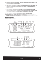
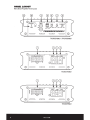
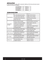
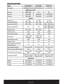
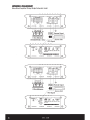
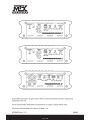
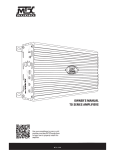
/'
"""
~
[:J
~
~
(
~I
I~CUJ [O)D«::D
.)
w
OWNER'S MANUAL
THUNDER SERIES AMPLIFIERS
Use your smartphone to scan or visit
youtube.com/user/MTXThunderforce
to learn how to properly install this
amplifier.
MTX.COM
PBODU CTINFO RMADO N
Model# --------- --------- --------- ---Serial# _____ _____ _____ __
Dealer's Name ________ ________ _________
Date of Purchase ________ ________ _________
INJ"ROD UCJ"ION
Thank you for purchasing this MTX Audio Hi-Performance amplifier. Proper installation matched
with MTX speakers and subwoofers provide superior sound and performance for endless hours of
enjoyment whether you are waking the neighbors or just out enjoying your tunes. Congratulations
and enjoy the ultimate audio experience with MTX!
FEAJ"URES
• Compact Size
• Double Sided PCB
• Surface Mount Components
• MOSFET Design
• LPF and HPF Crossover
• Adjustable Bass Boost
• Noise Free Design
• Short, Thermal, and High/Low Voltage Protection
CONJ"II OL FUNCJ" IONS
1. Speakers- Connect speakers/subwoofers to these terminals. Be sure to check wire for proper
polarity. Never connect the speaker cables to the chassis ground.
2. +BATT(+ 12 Volt Power)- Connect this terminal through a FUSE or CIRCUIT BREAKER to the
positive terminal of the vehicle battery or the positive terminal of an isolated audio system
battery. WARNING: Always protect this power cable by installing a fuse or circuit breaker of the
appropriate gauge within 18 inches (45cm) of the battery terminal connection.
3.
Remote Turn On- This terminal turns on the amplifier when(+) 12 volt is applied to it. Connect it to
the remote turn on lead of the head unit or signal source.
4. GND- Connect this cable directly to the frame of the vehicle. Make sure the metal frame has
been stripped of all paint down to the bare metal. Use the shortest distance possible. It is always
a good idea to replace the factory ground at this time with a cable equal or larger than the new
amplifier power cable. CAUTION: Do not connect this terminal directly to the vehicle battery
ground terminal or any other factory ground points.
2
5.
RCA Input Jacks- These RCA input jacks are for use with source units that have RCA outputs. A
source unit with a minimum level of 200mV is required for proper operation. The use of high
quality twisted pair cables is recommended to decrease the possibility of radiated noise entering
the system.
6.
Gain Control- The Gain control will match the amplifier's sensitivity to the source units signal
voltage. The operating range is 5V to 200mV. NOTE: This is NOT a volume control.
7.
Low Pass Filter Control (Mono Block) -This control is used to select the desired low pass x-over
frequency. The frequency can be adju.sted from 40Hz to 220Hz for all bass mono models.
8.
Subsonic Filter Control (Mono Block)- This control can filter out unwanted low frequency from
20Hz (OFF) to 50Hz. This function should only be used with vented enclosures.
MTX.COM
9.
Bass Boost Level Switch (Mono Block)- This switch can boost bass level by OdB, 6dB, or 12dB.
The boost frequency is centered at 50Hz.
10. High Pass Filter (Full Range)- This controls the frequencies played for the front channels. Low
frequencies can be cut off from OFF to 200Hz. At OFF position, no low frequencies cut off,
meaning full range.
11. X-Over Mode and Frequency Control (Full Range) -These controls allow control over the
frequencies played for the rear channels. There is an option for Low Pass, Full Range, or High
Pass. In LP or HP mode, the crossover frequency can be tuned from 50Hz to 750Hz.
12. Power Indicator- This LED will light up .when the amplifier is working properly.
13. Protection Indicator- The Red LED will light up and flash if there is a fault presented to the
amplifier. Please disconnect the amplifier and resolve the fault before reconnecting the amplifier.
PANEL LAYOU T
4-Channel Amplifier Panel Layout
FRONT
REAR
@
~
F
w
~
c(
w
0..
U)
R
©
00
00
D D
D D
00
00
D D
D D
0
©
D
0
D
0
D
@
MTX.COM
3
PANEL IJIYOU7
Mono Block Amplifier Panel Layout
THUNDER1000.1 I THUNDER500.1
0
D
~
0
~
0
0
D
THUNDER1000.1
+BATT
0
©
D
REM
~
0
r--
0
0
D
THUNDER500.1
MTX.COM
WIRING DIAGRAM
See page 26 for amplifier wiring diagrams.
INSTALLATION AND MOUNTING
MTX recommends your new THUNDER Series amplifier be installed by a 12 volt installation specialist.
Any deviation from specified installation instructions can cause serious damage to the amplifier,
speakers and/or vehicle's electrical system. Damage caused from improper installation is NOT
covered under warranty. Please verify all connections prior to system turn on.
1.
Disconnect the vehicle's negative battery cable.
2.
Determine the ·mounting place for your MTX amplifier. Keep in mind there should be sufficient
air flow for proper cooling. Mark the mounting holes from the amplifier to be drilled. Before
drilling make sure all vehicle wires, gas lines, brake lines and gas tank are clear and will not
interfere with installation. Drill the desired holes and mount the MTX amplifier.
3.
Install a positive (+) power cable from the vehicle's battery through the firewall using a grommet
or firewall bushing to avoid cable damage from sharp edges of the firewall. Run the cable through
the interior of the vehicle and connect it to the amplifier's (+BATT) terminal. Do not connect to the
battery at this time. NOTE: Use only proper gauge wire for both positive and negative connections.
4.
Install a circuit breaker or fuse within 18 inches of the battery. This effectively lowers the risk
of severe damage to you or your vehicle in case of a short circuit or accident. Make sure the
circuit breaker is switched Off or the fuse is taken out of the fuse holder untill all connections are
made. Now connect your positive power cable to the positive battery terminal of the battery.
5.
Grounding - Locate a proper ground point on the vehicle's chassis and remove all paint, dirt or
debris to reveal a bare metal surface. Attach the ground wire to that contact point. Connect the
opposite end of the ground wire to the (G NO) terminal on the MTX amplifier.
6.
Connect a Remote Turn-On wire from the source unit to the MTX amplifier's (REM) terminal. If the
source unit does not have a dedicated Remote Turn-On lead, you may connect to the source unit's
Power Antenna lead.
7.
Supply the signal to your MTX amplifier by connecting the signal cables using high quality RCA to
the corresponding outputs at the source unit and inputs of the amplifier.
8.
Connect your speakers to your MTX amplifier's speaker terminals using the correct gauge
speaker wire. Your MTX amp can drive a 2Q (THUNDER75.4 & THUNDER500.1) and 1Q
(THUNDER1000.1) minimum load for optimum power.
9.
Double check all previous installation steps, in particular, wiring and component connections.
Once verified, reconnect the vehicle's negative battery cable, turn the circuit breaker On or place
the fuse in the fuse holder.
NOTE: Gain Levels on the amplifier should be turned all the way down (counter clockwise) before
proceeding with adjustments.
MTX.COM
INSTALLATION
For proper perfomance and safety, MTX recommends installing an in line fuse per the owner's manual
instructions according to the following.
TH UNDERl 000.1
100A Fuse
THUNDER500.1
60A Fuse
THUNDER75.4
60A Fuse
TROUBLESHOOTING
Problem
No LED Indication
Power LED On,
No Output
Output Distorted
Balance Reversed
Bass is Weak
Blowing Fuses
Cause
Solution
No+ 12V at Remote Connection
Supply+ 12V to Terminal
No +12V at Power Connection
Supply+ 12V to Terminal
Insufficient Ground Connection
Verify Ground Connection
Blown Power Fuse
Replace Fuse
Volume on Source Unit Off
Increase Volume on Source Unit
Speaker Connections Not Made
Make Speaker Connections
Gain Control on Amplifier Off
Turn Up Gain
Signal Processing Units Off
Apply Power to Signal Processor
All Speakers Blown
Replace Speakers
Head Unit Volume Set Too High
Lower Head Unit Volume
Amplifier Gain Set Too High
Lower Amplifier Gain
Speaker Wire L & R Reversed
Correct Speaker Wire Orientation
RCA Inputs Reversed
Reverse RCA Inputs
Speakers Wired Out of Phase
Wire Speakers with Correct Phase
Not Using MTX Subwoofers
Buy MTX Subwoofers
Excessive Output Levels
Lower the Volume
Amplifier Defective
Return for Service
MTX.COM
SPECIFICADONS
Model
Description
THUNDER1000.1
THUNDER500.1
THUNDER75.4
1000 W RMS Mono
500 W RMS Mono
4x 75 W RMS
RMS Power at 14.4V
1Q Load
1000W RMS
NA
NA
2Q Load
600W RMS
500W RMS
4 X 100W RMS
4Q Load
350W RMS
300W RMS
4x75WRMS
0.2- 5V
0.2- 5V
0.2- 5V
Frequency Response
20Hz- 220Hz
20Hz- 220Hz
15Hz- 25kHz
Low Pass Filter (LPF)
40Hz-
2~0Hz
40Hz- 220Hz
50Hz- 750Hz (Rear)
NA
NA
10Hz- 200Hz (Front)
50Hz- 750Hz (Rear)
Subsonic Filter
20Hz- 50Hz
20Hz- 50Hz
NA
THO at4Q, lW
<0.3%
<0.3o/o
<0.05%
Signal-to-Noise Ratio
>75dB
>75dB
>78dB
0-6dB-12dB
Switch able
0-6dB-12dB
Switch able
NA
>80%
>80%
>60o/o
Minimum Load
1Q
2Q
2Q
.External Bass Control (EBC)
Optional Remote
Yes
Yes
NA
Yes, Protect <8V
Yes, Protect <8V
Yes, Protect <8V
Short Circuit Test@ Max Power
Pass
Pass
Pass
Overheat Protect Temperature
Protect at 80°C I
176°F
Protect at 80°C I
176°F
Protect at 80°C I
176°F
SMD Parts I Double
Sided FR-4 PCB
SMD Parts I Double
Sided FR-4 PCB
SMD Parts I Double
Sided FR-4 PCB
Features
Input Level
High Pass Filter (HPF)
Bass Boost
Best Efficiency at 4Q
Low Voltage Protection
Components & PCB
Dimensions
Height
2.25" (56.5mm)
2.25" (56.5mm)
2.25" (56.5mm)
Width
6.31" (160mm)
6.31" (160mm)
6.31" (160mm)
Length
12.13" (308.5mm)
8.94" (227.5mm)
12.13" (308.5mm)
MTX.COM
WIRING DIAGRAifll
Mono Block Amplifier Wiring (Single Subwoofer Load)
@;:::=.=::::J------r=::==:J--c:::==:J--c::==>._@
~©
©LQilQJ
·-
~
c::::r:b
I
~
I
@
l_
I FdsE ~
Re-mote Signal
+&bl
1 Ohm Minimum
(THUNDER1000.1 Only)
lol
· . . . . . . ,_, ,., _, _.,. Source Unit
RCA Signal
c=cb
~
q~
~
~
I FJSE ~
Re-mote Signal
+&lol
2 Ohm Minimum
~<?;.";;·
1ol
source unl't
RCA Signal
.-.
.,-~··<'o'.o"'""'""""'""""'""'J
@ ;:::=.:==:J-~;t::::J--:::;;-c:::::==:::J--c::==>.,.@ .
PRoTEcr
O
Ps;R
EBC
0
©
p.,·~
0 WMi~Ax 40~iOHz O~OHz
'5'
R
~
~@
~
26
BAss
BOOST
GAIN
LPF
SUBSONIC
OdB12dB
TlllllfiiiEII500-.,
MTX.COM
WIRING DIAGRAM
Mono Block Amplifier Wiring (Multi-Subwoofer Load)
NOTE: Equivalent parallel woofer load cannot be less than the minimum load rating. The two negative
terminals are paralleled inside the amplifiers, as are the two positive terminals. These are monoblock
amplifiers, not multi-channel amplifiers. The minimum load for the THUNDER500.1 amplifier is 2Q.
The minimum load for the THUNDER1000.1 amplifier is 1Q.
NOTA: La carga equivalente de woofers paralelos no puede ser me nos que el valor nominal de Ia
carga. Las dos terminates negativas estan en para lela dentro de los amplificadores y tam bien las
terminates positivas. Estos son amplificadores de monobloque, no amplificadores multicanal. La
carga minima para el amplificador THUNDER500.1 es 2 Q. La carga minima para el amplificador
THUNDER1000.1 es 1 Q.
OBSERVA(:AO: A carga para lela equivalente do woofer nao pode ser me nor que a carga nominal
minima. Os dais terminais negativos, assim como os terminais positivos, estao em paralelo dentro
dos amplificadores. Os amplificadores sao monobloco e nao amplificadores multicanais. A carga
minima do amplificador THUNDER500.1 e 2Q. A carga minima do amplificador THUNDER1000.1 e 1Q.
REMARQUE : Une charge de caisson de graves en parallele ne peut etre inferieure a Ia valeur
nominale minimale de charge. Les deux barnes negatives sont mises en parallele a l'interieur des
amplificateurs, com me le sont les deux barnes positives. Ce sont des amplificateurs mono blocs et
non des amplificateurs multi-can aux. La charge minimale pour l'amplificateur THUNDER500.1 est de
2 Q. La charge minimale pour l'amplificateur THUNDER1000.1 est de 1 Q.
MTX.CO M
27
WIRING DIAGRAIIII
THUNDER75.4 Amplifier Wiring (4-Channel Mode)
oe
~
----------~f'~~
: ~,~
, --~-----------------+BATT
REM
GND
o:;-o
m
~
~Roo
© 9
0
<±;J L ,.e
©
f---H'"""-
©C!J ~o[J
.
<±>~Rie
c:::=:=p~: ;: c::::;a=p
~
~b
::
,'j
.
~
........,~~~~=-t"=;;;;;;;;;~~r~~-,~~~=ln
oe
1
~
~
ot:::=:>
i
~
@
F~sE 1 -!-
+tl. I
Remote Signal
Y o1
1ol
~ ~Source Unit
RCA Signal
RCA Signal
@ ~
@
L~r~ ~~NT 01 ~~R ftm e;lg
R
'@©I@
~ ~
FRONT
REAR
c:=::::::::)
MiN MAx r 1 MiN MAX 1 Fk
OFF 200Hz
r 1
PWR
TIIUifiDER76-4
.·.
28
1
LPF HPF 50Hz 750Hz
MTX.CO M
WIRING DIAGRAM
THUNDER75.4 Amplifier Wiring (3-Channel Mode)
oe
~
;
~¥
~
11
· ~~~~~~~~~--~---------------~,~~~
I FUSE l
+. I
Remote Signal
4-0hm to 8-0hm
RCA Signal
@
I-
I
:
L~7§ ~~NT 011~R ftm
R
0
tR:..
~~
FRONT
REAR
MiN MAx r 1 MiN MAx 1 Fk
OFF 200H•
1
Fe.lg
1
r
@
PWR
LPF HPF SOH• 7SOH•
TIIUIIIIIEII75_4
c::::::::::::>
MTX.CO M
29
FRONT
REAR
© 2012 Mitek Corporation. All rights reserved. MTX is a trademark of Mitek Corporation. Designed and
Engineered in the U.S.A.
Due to continual product development, all specifications are subject to change without notice.
MTX Audio, 4545 East Baseline Rd. Phoenix, AZ 85042 U.S.A.
MTX004553 RevA 11/12
NDM661
MTX.COM
Mitek Mobile Limited Warranty
Our Guarantee
Mitek Mobile products (including MTX, Streetwires, Coustic and Magnum) purchased in the USA after
1/1/2013 from an authorized Mitek retailer are guaranteed to be free from material defects in products
and workmanship for five (5) years to the original end user purchaser, subject to the terms and conditions
below.
Length of Limited Warranty and Remedy
The warranty period begins the day the product is purchased by the end user, and is limited to the original
retail purchaser of the product.
Free Replacement Period (2 Years)
Products found to be defective in materials or workmanship during the first 2 years will be, at Mitek's
option, repaired or replaced by Mitek at no charge. When a product is replaced during first 2 years, the
warranty does not renew, it continues on from the original date of purchase.
Proration Period (Years 3-5)
The prorated purchase price of any product which becomes defective after the first two years and prior to
the end of the warranty period may be credited toward the purchase of a new Mitek product. The amount
of the proration shall be determined by dividing the purchase price by the number of months of the
warranty period (60), and then multiplying the result by the number of months remaining in the warranty
period. Any partial months will be rounded to the nearest whole month. For example, a product purchased
37 months ago for $100 would be calculated by dividing $100 by 60 months = $1.66/month, multiplied by
23 (the months remaining in the warranty period) for a prorated warranty amount of $38.33.
You are responsible for all costs for removal, reinstallation and proper packaging, shipping, insurance or
other freight charges incurred in the shipment of the product or part to Mitek. Mitek will ship the repaired
or replaced Mitek product or replacement parts to you at no charge. Mitek reserves the right to utilize
reconditioned, refurbished, repaired or remanufactured products or parts in the warranty repair or
replacement process. Such products and parts will be comparable in function and performance to an
original product or part and warranted for the remainder of the original warranty period.
What Is Not Covered
This warranty does not cover the product if it has been subject to neglect, abuse, misuse, incorrect
connection, or if it has been subject to unauthorized repair or alterations of any nature, or if the serial
number has been altered or removed, and the warranty does not extend to cosmetics or finish. This
warranty only applies to products installed and used in the USA.
What You Must Do to Obtain Warranty Service
You must contact Mitek Warranty via our website at MTX.com, or via email at
[email protected], or by calling 800-556-2888. If you did not purchase the product directly from
Mitek, a proof of purchase must be provided in order to receive warranty consideration. You will be issued
a Return Authorization (RA) number which must be written on the outside of the package before returning
the product to Mitek.
No Other Warranties
THE LIMITED WARRANTIES DESCRIBED ABOVE ARE EXCLUSIVE AND IN LIEU OF ANY OTHER
WARRANTIES, EXPRESS OR IMPLIED. MITEK DISCLAIMS AND EXCLUDES ALL OTHER EXPRESS
WARRANTIES, AND DISCLAIMS AND EXCLUDES ALL WARRANTIES IMPLIED BY LAW, INCLUDING
WITHOUT LIMITATION THOSE OF MERCHANTABILITY AND FITNESS FOR A PARTICULAR
PURPOSE. TO THE EXTENT THAT APPLICABLE LAW PROHIBITS THE EXCLUSION OF IMPLIED
WARRANTIES, THE DURATION OF ANY APPLICABLE IMPLIED WARRANTY IS LIMITED TO THE
PERIOD SPECIFIED FOR THE EXPRESS WARRANTY. Some states do not allow limitations on how
long an implied warranty lasts, so the above limitation may not apply to you. Any oral or written
description of any Mitek product is for the sole purpose of identifying it and shall not be construed as an
express warranty.
Limitation of Liability
MITEK'S OBLIGATION TO PROVIDE A CREDIT, OR REPAIR OR REPLACE AT MITEK'S OPTION,
SHALL BE YOUR SOLE AND EXCLUSIVE REMEDY UNDER THIS LIMITED WARRANTY AND
MITEK'S SOLE AND EXCLUSIVE OBLIGATION. MITEK SHALL NOT BE LIABLE FOR INCIDENTAL,
INDIRECT, CONSEQUENTIAL OR SPECIAL DAMAGES ARISING OUT OF OR IN CONNECTION WITH
THE MITEK PRODUCT, ITS USE OR PERFORMANCE. Incidental damages include, but are not limited
to, such damages as loss of time and loss of use. Consequential damages include, but are not limited to,
the cost of repairing or replacing other property which was damaged if the Mitek product does not work
properly.
Some states do not allow the exclusion or limitation of incidental or consequential damages, so the above
limitation or exclusion may not apply to you. This warranty gives you specific legal rights, and you may
also have other rights, which vary from state to state. This limited warranty supersedes all prior warranties
and is not transferable from the original consumer purchaser.
Any assistance Mitek provides to or procures for you outside the terms, limitations or exclusions of this
limited warranty will not constitute a waiver of such terms, limitations or exclusions, nor will such
assistance extend or revive the warranty. Mitek will not reimburse you for any expenses incurred by you
in repairing or replacing any defective product, except for those incurred with Mitek's prior written
permission.