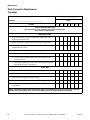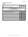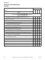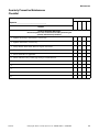
1
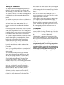
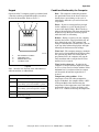
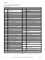
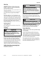
Pocket Hardmount
Variable Speed
V-Series Microcomputer
Refer to Page 7 for Model Identification
www.comlaundry.com
Operation/Maintenance
Washer-Extractors
Table of
Contents
Safety Information..............................................................................
Explanation of Safety Messages...........................................................
Important Safety Instructions ...............................................................
Safety Decals ........................................................................................
3
3
3
6
Operation.............................................................................................
Model Identification .............................................................................
Customer Service..................................................................................
Machine Familiarization Guide ............................................................
Theory of Operation .............................................................................
V-Computer .....................................................................................
Keypad .............................................................................................
Conditions Monitored by the Computer ..........................................
Start-Up.................................................................................................
Opening Door .......................................................................................
Loading .................................................................................................
Cycle Selection .....................................................................................
Cycle Execution....................................................................................
Fill ....................................................................................................
Wash ................................................................................................
Drain ................................................................................................
Spin ..................................................................................................
Stop Routine .........................................................................................
Balance Detection.................................................................................
Motor Thermal Overload Indicator ......................................................
7
7
7
9
10
10
11
11
13
13
13
13
14
14
14
15
15
15
16
16
Maintenance ........................................................................................
Daily .....................................................................................................
Beginning of Day .............................................................................
End of Day .......................................................................................
Weekly..................................................................................................
Monthly.................................................................................................
Quarterly ...............................................................................................
Care of Stainless Steel ..........................................................................
Daily Preventive Maintenance Checklist..............................................
Weekly Preventive Maintenance Checklist ..........................................
Monthly Preventive Maintenance Checklist.........................................
Quarterly Preventive Maintenance Checklist .......................................
17
17
17
18
18
18
20
21
22
23
24
25
Removal from Service ........................................................................ 27
Decommissioning ................................................................................. 27
© Copyright 2006, Alliance Laundry Systems LLC
All rights reserved. No part of the contents of this book may be reproduced or transmitted in any form or by any
means without the expressed written consent of the publisher.
F232183
© Copyright, Alliance Laundry Systems LLC – DO NOT COPY or TRANSMIT
1
Notes
2
© Copyright, Alliance Laundry Systems LLC – DO NOT COPY or TRANSMIT
F232183
Safety Information
Explanation of Safety Messages
Precautionary statements (“DANGER,” “WARNING,”
and “CAUTION”), followed by specific instructions,
are found in this manual and on machine decals. These
precautions are intended for the personal safety of the
operator, user, servicer, and those maintaining the
machine.
Important Safety Instructions
WARNING
To reduce the risk of fire, electric shock,
serious injury or death to persons when
using your washer, follow these basic
precautions:
W023
DANGER
1. Read all instructions before using the washer.
DANGER indicates the presence of a
hazard that will cause severe personal
injury, death, or substantial property
damage if the danger is ignored.
WARNING
WARNING indicates the presence of a
hazard that can cause severe personal
injury, death, or substantial property
damage if the warning is ignored.
CAUTION
CAUTION indicates the presence of a
hazard that will or can cause minor
personal injury or property damage if the
caution is ignored.
Additional precautionary statements (“IMPORTANT”
and “NOTE”) are followed by specific instructions.
IMPORTANT: The word “IMPORTANT” is used
to inform the reader of specific procedures where
minor machine damage will occur if the procedure
is not followed.
NOTE: The word “NOTE” is used to communicate
installation, operation, maintenance or servicing
information that is important but not hazard
related.
2. Refer to the GROUNDING INSTRUCTIONS in
the INSTALLATION manual for the proper
grounding of the washer.
3. Do not wash textiles that have been previously
cleaned in, washed in, soaked in, or spotted with
gasoline, kerosene, waxes, cooking oils, drycleaning solvents, or other flammable or
explosive substances as they give off vapors that
could ignite or explode.
4. Do not add gasoline, dry-cleaning solvents, or
other flammable or explosive substances to the
wash water. These substances give off vapors that
could ignite or explode.
5. Under certain conditions, hydrogen gas may be
produced in a hot water system that has not been
used for two weeks or more. HYDROGEN GAS
IS EXPLOSIVE. If the hot water system has not
been used for such a period, before using a
washing machine or combination washer-dryer,
turn on all hot water faucets and let the water
flow from each for several minutes. This will
release any accumulated hydrogen gas. The gas is
flammable, do not smoke or use an open flame
during this time.
6. Do not allow children to play on or in the washer.
Close supervision of children is necessary when
the washer is used near children. This is a safety
rule for all appliances.
7. Before the washer is removed from service or
discarded, remove the door to the washing
compartment.
8. Do not reach into the washer if the wash drum is
moving.
F232183
© Copyright, Alliance Laundry Systems LLC – DO NOT COPY or TRANSMIT
3
Safety Information
9. Do not install or store the washer where it will be
exposed to water and/or weather.
10. Do not tamper with the controls.
11. Do not repair or replace any part of the washer, or
attempt any servicing unless specifically
recommended in the user-maintenance
instructions or in published user-repair
instructions that the user understands and has the
skills to carry out.
12. To reduce the risk of an electric shock or fire, DO
NOT use an extension cord or an adapter to
connect the washer to the electrical power source.
13. Use washer only for its intended purpose,
washing textiles.
14. Never wash machine parts or automotive parts in
the machine. This could result in serious damage
to the basket.
15. ALWAYS disconnect the washer from electrical
supply before attempting any service. Disconnect
the power cord by grasping the plug, not the cord.
16. Install the washer according to the
INSTALLATION INSTRUCTIONS. All
connections for water, drain, electrical power and
grounding must comply with local codes and be
made by licensed personnel when required.
17. To reduce the risk of fire, textiles which have
traces of any flammable substances such as
vegetable oil, cooking oil, machine oil,
flammable chemicals, thinner, etc., or anything
containing wax or chemicals such as in mops and
cleaning cloths, must not be put into the washer.
These flammable substances may cause the
fabric to catch on fire by itself.
18. Do not use fabric softeners or products to
eliminate static unless recommended by the
manufacturer of the fabric softener or product.
20. Replace worn power cords and/or loose plugs.
21. Be sure water connections have a shut-off valve
and that fill hose connections are tight. CLOSE
the shut-off valves at the end of each wash day.
22. Loading door MUST BE CLOSED any time the
washer is to fill, tumble or spin. DO NOT bypass
the loading door switch by permitting the washer
to operate with the loading door open.
23. Always read and follow manufacturer’s
instructions on packages of laundry and cleaning
aids. Heed all warnings or precautions. To reduce
the risk of poisoning or chemical burns, keep
them out of the reach of children at all times
(preferably in a locked cabinet).
24. Always follow the fabric care instructions
supplied by the textile manufacturer.
25. Never operate the washer with any guards and/or
panels removed.
26. DO NOT operate the washer with missing or
broken parts.
27. DO NOT bypass any safety devices.
28. Failure to install, maintain, and/or operate this
washer according to the manufacturer’s
instructions may result in conditions which can
produce bodily injury and/or property damage.
NOTE: The WARNINGS and IMPORTANT
SAFETY INSTRUCTIONS appearing in this
manual are not meant to cover all possible
conditions and situations that may occur. Common
sense, caution and care must be exercised when
installing, maintaining, or operating the washer.
Any problems or conditions not understood should be
reported to the dealer, distributor, service agent or the
manufacturer.
19. Keep washer in good condition. Bumping or
dropping the washer can damage safety features.
If this occurs, have washer checked by a qualified
service person.
4
© Copyright, Alliance Laundry Systems LLC – DO NOT COPY or TRANSMIT
F232183
Safety Information
WARNING
CAUTION
This machine must be installed, adjusted,
and serviced by qualified electrical
maintenance personnel familiar with the
construction and operation of this type of
machinery. They must also be familiar
with the potential hazards involved.
Failure to observe this warning may result
in personal injury and/or equipment
damage, and may void the warranty.
SW004
CAUTION
Ensure that the machine is installed on a
level floor of sufficient strength and that
the recommended clearances for
inspection and maintenance are provided.
Never allow the inspection and
maintenance space to be blocked.
Be careful around the open door,
particularly when loading from a level
below the door. Impact with door edges
can cause personal injury.
SW025
WARNING
Never touch internal or external steam
pipes, connections, or components.
These surfaces can be extremely hot and
will cause severe burns. The steam must
be turned off and the pipe, connections,
and components allowed to cool before
the pipe can be touched.
SW014
SW020
F232183
© Copyright, Alliance Laundry Systems LLC – DO NOT COPY or TRANSMIT
5
Safety Information
Safety Decals
Safety decals appear at crucial locations on the
machine. Failure to maintain legible safety decals
could result in injury to the operator or service
technician.
To provide personal safety and keep the machine in
proper working order, follow all maintenance and
safety procedures presented in this manual. If
questions regarding safety arise, contact the
manufacturer immediately.
6
© Copyright, Alliance Laundry Systems LLC – DO NOT COPY or TRANSMIT
F232183
Operation
Model Identification
Customer Service
Information in this manual is applicable to these
models:
If literature or replacement parts are required, contact
the source from which the machine was purchased
or contact Alliance Laundry Systems LLC at
(920) 748-3950 for the name and address of the
nearest authorized parts distributor.
UW35VV*
UW60VV*
UW80VV*
UW100VV*
UW125VV*
For technical assistance, call any of the following
numbers:
*This manual applies to models with U7 or U8 in the
8th and 9th or 9th and 10th positions in the model
number (e.g., UW60VVXU70001).
This manual is designed as a guide to operating and
maintaining the pocket hardmount washer-extractor
equipped with the V-computer and AC inverter drive.
(920) 748-3121
Ripon, Wisconsin
www.comlaundry.com
A record of each machine is on file with the
manufacturer. Always provide the machine’s serial
number and model number when ordering parts or
when seeking technical assistance.
The manuals, installation instructions, and wiring
diagrams which accompany the machine have been
included with the machine at no charge. Additional
copies are available at a nominal charge.
NOTE: Read this manual thoroughly before
attempting to operate the machine.
NOTE: Do not use this manual in conjunction with
earlier model computer-controlled machines. Do
not use technical literature intended for earlier
models when operating this machine.
NOTE: All information, illustrations, and
specifications contained in this manual are based
on the latest product information available at the
time of printing. We reserve the right to make
changes at any time without notice.
F232183
© Copyright, Alliance Laundry Systems LLC – DO NOT COPY or TRANSMIT
7
Operation
Model Number Familiarization Guide
Sample Model Number: UW60VVXU70001
UW
Model Number Prefix
60
Washer-Extractor Capacity (pounds dry weight of laundry)
V
Type of Electrical Control
V
Washer-Extractor Speed Capabilities
X
Electrical Characteristics
7
Design Series
0001
Option Identification (varies from machine to machine)
UW60VVXU70001
00000000000
200 – 240
20
50 – 60
2/3
60
N/A
14
1/3
27
N/A
813
0.0
Drawings:
ETL Listed
Conforms To ANSI/UL Std. 1206, 3rd Ed
Certified To CAN/CSA Std. C22.2 No.53-1968
EXAMPLE OF NAMEPLATE
PHM628N
PHM628N
Figure 1
8
© Copyright, Alliance Laundry Systems LLC – DO NOT COPY or TRANSMIT
F232183
Operation
Machine Familiarization Guide
The machine familiarization guide in Figure 2
identifies the major operational features of the
machine.
P005I
1
2
3
4
5
6
7
Emergency Stop Button
Supply Valve Box
Supply Dispenser
Door Handle
Door Box
Door Latch Extension Arm
Door Latch
8
9
10
11
12
13
14
Side Panel
Front Panel
Rub Rail
Shell Front
Door Hinge
Door
Control Module
Figure 2
F232183
© Copyright, Alliance Laundry Systems LLC – DO NOT COPY or TRANSMIT
9
Operation
Theory of Operation
The design of the machine emphasizes performance
reliability and long service life. The cylinder, shell,
and main body panels are fabricated of stainless steel.
The cylinder is driven by a belt-drive system supported
via the shaft by two flange-mounted spherical roller
bearings bolted to the A-frame. The UW35 uses a
trunion.
The machine uses one motor to drive the cylinder via a
V-belt drive in all speeds.
A door-lock system prevents opening of the stainless
steel door when water is in the machine. It also
prevents operation of the machine when the door is
open.
Electrically operated drain valves are used to retain the
water and wash solution in the machine during the
wash and fill steps. The drain valve closes when power
is applied and opens when power is removed, allowing
the machine to drain in the event of a power failure.
The cylinder is designed with lifters or ribs that lift the
garments from the wash solution when the cylinder
rotates at slow speed and allow the garments to tumble
back into the solution. The cylinder is perforated,
allowing the water to pass through and drain from
within during the wash process and extract.
Electrical controls for the machine are housed in a
separate enclosure located underneath the top cover of
the machine.
There are two possible load balance systems, the “AC
Inverter Drive Balance Detection” and the “Vibration
Safety Switch.”
The machine uses an AC inverter drive control which
provides five motor speeds using a single motor. The
solid state output board converts motor logic from the
V-computer to the correct signals for the AC inverter
drive.
The operator can select from among 30 cycles. A
special permanent test cycle can be selected to verify
proper operation of the machine.
Liquid supplies can be injected directly into the cups
by a customer-supplied external chemical supply
system. Five hose strain reliefs on top of the supply
dispenser facilitate connection to an external supply
system. A terminal strip inside a panel on the rear of
the control module provides connection points for
external supply signals.
V-Computer
The V-computer control is a programmable solid-state
control capable of storing and running up to 30 cycles.
A detailed description of these cycles can be found in
the Programming section of this manual.
If this machine’s computer has been equipped with
special preprogrammed cycles, a separate insert listing
these cycles has been included in the resealable plastic
bag which contained this manual.
NOTE: Never turn the power off while the
computer mode switch is in the Program position.
Such action will disorder portions of the
programmed data, necessitating reprogramming of
some or all of the existing cycles. Always return the
mode switch to Run position before turning the
power off. Refer to the Programming Manual.
The balance detection system using the vibration
safety switch does not rely on the AC inverter drive
and does not attempt to balance the load in a drain
step. As the cylinder is spinning at the programmed
speed, if the wash load becomes unbalanced, the
overtravel limit switch is “tripped” causing the
cylinder to slow to a stop. The remaining portion of the
cycle is aborted.
The balance detection system using the AC inverter
drive uses special balance detection software in
conjunction with the V-computer to prevent out-ofbalance conditions. When the AC drive detects an
unbalanced load during the drain step, the computer
will make up to three attempts to balance the load.
After the third try the machine spins at a safe speed up
to 106 G. As a fail-safe measure, a vibration safety
switch is installed.
10
© Copyright, Alliance Laundry Systems LLC – DO NOT COPY or TRANSMIT
F232183
Operation
Keypad
Conditions Monitored by the Computer
Operation of the V-computer control is performed with
a four-key touch keypad and LED display located on
the front of the machine. Refer to Figure 3.
1
2
3
4
●
Door – The computer continuously monitors
the open/locked status of the door. If it detects
that the door is open during a wash cycle, it
immediately aborts the cycle and executes the
stop routine.
●
Power – If power is interrupted long enough
for the computer to go off, after the power is
restored, the display flashes “Hold” briefly to
indicate the interruption. The door unlock will be
disabled to keep the door from being opened
while the basket is still turning.
●
Balance – During a regular cycle, the computer
monitors the balance signal provided by the AC
drive during drain steps. The computer will
attempt to distribute the load three times. The dot
at the top of the leftmost display digit will light
following the final unsuccessful attempt.
●
Water level – The computer attempts to maintain
the water level programmed for the fill preceding
the agitation step. If the level falls below the
programmed level, the computer will stop the
time countdown and re-energize the fill valves
until the level is restored.
●
Water level in a heat step – In order for the
computer to energize the heat output, there must
be at least a low water level in the machine. If this
minimum level is not detected, the heat output
will be turned off until the required level is
restored.
●
Temperature probe problem – If the
temperature sensor fails when prompted for
degrees Fahrenheit, the computer flashes “tSFL”
in Program Mode rather than showing the
temperature. If the temperature sensor fails when
prompted for degrees Celsius, the display will
read “-17C” rather than showing the temperature.
PHM199R
1
2
3
4
Out-of-Balance Condition
High Water Level
Medium Water Level
Low Water Level
Figure 3
Table 1 describes the function of the individual keys
when the machine is in Run Mode.
Keypad
Key
Description
Up
Used in cycle selection; pressing this key
moves among cycles from smaller to greater.
Down
Used in cycle selection; pressing this key
moves among cycles from greater to smaller.
Start
Used to start a cycle.
Stop
Used to stop a cycle.
Table 1
F232183
© Copyright, Alliance Laundry Systems LLC – DO NOT COPY or TRANSMIT
11
Operation
Table 2 lists the various displays and what they mean.
The operator should become familiar with these
computer displays.
Display Indications
Display
Display
SPC?
Meaning
Special test cycle function (if present, ignore)
vv01
Meaning
Program identification code (ROM)
Example only.
Lo
Low water level
Hold
Wait...power has just been turned on.
nEd
Medium water level
CY
Cycle (followed by two-digit number)
HI
High water level
tESt/CYC*
Test cycle selected.
SUP1
Supply 1
FAr
Degrees Fahrenheit
SUP2
Supply 2
CEL
Degrees Celsius
SUP3
Supply 3
HEAt
Auxiliary heat enabled.
SUP4
Supply 4
noHt
Auxiliary heat disabled.
SUP5
Supply 5 (SETUP option)
tFIL
Temperature-controlled fill enabled.
SUP6
Supply 6 (supply 1 and 5)
ntFL
Temperature-controlled fill disabled.
SUP7
Supply 7 (supply 3 and 4)
CooL
Automatic cool-down enabled.
SLo/For**
Gentle wash speed, forward direction
noCL
Automatic cool-down disabled.
SLo/rEv**
Gentle wash speed, reverse direction
Ag 1
Agitation 1 selected (90% agitation).
norn/For
Normal wash speed, forward direction
Ag 2
Agitation 2 selected (33% agitation).
norn/rEv
Normal wash speed, reverse direction
Ag 3
Agitation 3 selected (10% agitation).
drAI
Drain enabled.
Ag 4
Agitation 4 selected (6.7% agitation).
nodr
Drain disabled.
AgSn
Agitation speed normal
dISt
Distribution (load balancing before extract)
AgSL**
Agitation speed low
PUnP
Pump output enabled (future use only).
SPIn/tInE*
Reads “SPIn” for one second, then “tInE” followed by
time for spin.
nPnP
Pump output disabled (future use only).
SPn1
Lowest of three spins
PrE
PreWash segment (1st of 11 segments)
SPn2
Middle of three spins
UASH
Wash segment (2nd of 11 segments)
SPn3
Highest of three spins
FIL1
First fill (3rd of 11 segments)
STOP
Stop routine
FIL2
Second fill (4th of 11 segments)
SdLY
Spin coast delay
FIL3
Third fill (5th of 11 segments)
donE
Cycle and stop routine have ended.
FIL4
Fourth fill (6th of 11 segments)
dFLt
Drive fault detected.
FIL5
Fifth fill (7th of 11 segments)
door
Door not properly closed.
FIL6
Sixth fill (8th of 11 segments)
BAL/door*
Indicates vibration switch or door locked switch tripped
during spin.
FIL7
Seventh fill (9th of 11 segments)
FIL8
Eighth fill (10th of 11 segments)
FIL9
Ninth fill (11th of 11 segments)
CFIL
Cold fill
bFIL
Warm fill (both hot and cold)
HFIL
Hot fill
AFIL
Auxiliary fill (SETUP option)
Programmed water level not reached after
FILL/STOP* 30 minutes.
FULL
tSFL
bAL?
The computer detects low water level or higher when
none should be present.
Temperature sensor failure or temperature out of range.
Special test cycle function (if present, ignore)
* Display indications separated by a slash represent a flashing display.
** The washer-extractor will operate at normal wash speed regardless of the speed settings.
Table 2
12
© Copyright, Alliance Laundry Systems LLC – DO NOT COPY or TRANSMIT
F232183
Operation
Start-Up
IMPORTANT: Remove all sharp objects from
laundry to avoid tears and rips to items during
normal machine operation.
Turn on the main power source (circuit breaker or cutoff switch on the wall).
An identification code will appear for approximately
five seconds. Then the display will flash “Hold”
briefly.
The display will then read “CY” followed by a twodigit cycle number (01 – 30) to indicate that a cycle
can be selected. This display will be shown at all times
when power is on between cycles, indicating that the
door-unlock solenoid will function if the door-unlock
button is pressed. Run the Test Cycle before operating
the washer-extractor. Refer to Test Cycle in the
Programming Manual. The machine is then ready for
loading and unloading.
WARNING
Never operate the machine with a
bypassed or disconnected balance
system. Operating the machine with
severe out-of-balance loads could result
in personal injury and serious equipment
damage.
SW039
When loading is complete, ensure that all fabric is
inside the basket. Then close and lock the door by
fully rotating the door handle counterclockwise. The
machine should not start or run unless the door is both
closed and locked.
CAUTION
Check the door safety interlock daily
before the machine is placed in operation.
SW024
Opening Door
Press and hold the door-unlock button and pull door
handle clockwise.
NOTE: When washing items which may
disintegrate, such as mop heads or sponges, use
laundry net bags to prevent drain blockage.
Loading
Cycle Selection
CAUTION
NOTE: Press keys at their centers just hard enough
to activate them.
Be careful around the open door,
particularly when loading from a level
below the door. Impact with door edges
can cause personal injury.
SW025
Load the machine to full capacity whenever possible,
but do not exceed the rated dry-weight capacity of the
machine if the fabric to be washed is quite dense,
closely woven, and heavily soiled. Overloading can
result in an inferior wash. Underloading can result in
poor load distribution potentially causing the extract
speed to be limited. The operator may need to
experiment to determine load size based on fabric
content, soil content, and level of cleanliness required.
Press the Up or Down key until the desired cycle
number is displayed. The computer will skip blank
(unprogrammed) cycles automatically. Press the Start
key to start the cycle. For a more detailed description
of the preprogrammed cycles, refer to the cycle charts
at the end of the Programming Manual.
If the computer detects that the door is not properly
closed when the Start key is pressed, the display will
read “door” until the door is closed and locked. Press
Start again to begin the desired cycle.
NOTE: Underloading can cause out-of-balance
conditions which shorten life of bearing, seals,
basket/shaft assembly, etc.
F232183
© Copyright, Alliance Laundry Systems LLC – DO NOT COPY or TRANSMIT
13
Operation
Cycle Execution
Wash
A cycle can be stopped at any time by pressing the
Stop key. The machine will go to the stop routine.
When the routine is complete, the display shows
“donE” until the door is unlocked.
As soon as water level is reached (and any
programmed temperature is reached), the displayed
time begins counting down at one-second intervals.
To display the temperature of the water while a cycle
is running, press the Up key. To display the number of
the cycle in progress, press the Start key.
Agitation is active during this portion of the segment.
There are four different agitation actions available.
Refer to Table 3 for more information.
Agitation Action Options
NOTE: The computer does not count down the
remaining cycle time during fills, drains, cooldown, or prior to first achieving the programmed
heat temperature when heating. The computer
resumes counting down cycle time once the
programmed fill level is reached, when the machine
has drained, and after a programmed heat
temperature is reached.
Display
Description
Percentage
Ag 1
27 seconds forward,
3 seconds pause,
27 seconds reverse,
3 seconds pause
90%
Ag 2
10 seconds forward,
20 seconds pause,
10 seconds reverse,
20 seconds pause
33%
Ag 3
3 seconds forward,
27 seconds pause,
3 seconds reverse,
27 seconds pause
10%
Ag 4
4 seconds forward,
56 seconds pause,
4 seconds reverse,
56 seconds pause
6.7%
Each of the 30 cycles consists of 11 segments:
PreWash, Wash, and Fills 1 – 9. A description of the
various steps in a cycle segment follows:
Fill
After the Start key is pressed, the drain closes and the
machine begins filling to the programmed level. Each
programmed segment begins with a fill. The display
counts down the remaining cycle time in minutes and
seconds while the cycle is running.
If a supply is programmed in a step, the supply
dispenser will flush during the fill of that segment.
If the machine is connected to an external chemical
supply system, the programmed supply will begin
10 seconds into the fill. The supply will remain on
until the programmed water level is reached, or until
60 seconds have elapsed, whichever happens first.
If agitation options 1 or 2 are selected for the cycle
program, the cylinder will rotate slowly during the fill
step. If agitation options 3 or 4 are selected for the
cycle program, the cylinder will not rotate during the
fill step. Refer to Table 3 for more information.
Table 3
If the segment contains a heat step, the machine begins
heating after the water has reached the programmed
level.
NOTE: If the water does not reach the
programmed temperature in 40 minutes, the
computer progresses to the wash step.
If the computer does not receive a signal that water
level has been attained within 30 minutes, it will
alternately flash “STOP” and “FILL” and sound the
on-board beeper for ten seconds. The computer will
then initiate the stop routine.
14
© Copyright, Alliance Laundry Systems LLC – DO NOT COPY or TRANSMIT
F232183
Operation
Drain
Stop Routine
If the cycle program segment calls for a drain, the
drain valves will open after the programmed segment
time has elapsed. If a spin step follows a drain step, the
cylinder will turn clockwise (forward) at wash speed
for several seconds at the beginning of the drain step.
This clockwise direction mirrors the spin rotation and
is, therefore, also considered forward.
When the computer concludes the wash cycle or when
the Stop key is pressed while a cycle is in progress, the
computer goes into the stop routine.
The cylinder then accelerates to distribution speed to
help ensure that the load is evenly distributed. The
drains open several seconds later.
NOTE: The machine should drain in 30 seconds. If
the machine fails to drain, contact a qualified
service technician.
If the cycle program segment does not call for a drain,
the computer moves to the next segment of the cycle
program. If the segment is at the end of a cycle
program, the computer goes into the stop routine.
If the cycle program segment does not call for a spin,
the cylinder will continue to turn at wash speed
throughout the drain step. When the drain has
completed, the computer moves to the next segment of
the cycle program. If the segment is at the end of a
cycle program, the computer goes into the stop
routine.
NOTE: The drain step in the final segment (Fill 9)
cannot be skipped.
Spin
After the drain sequence ends, the speed of the
cylinder increases to the extract speed if the
programmed spin time is not zero. The displayed time
resumes counting down at one-second intervals.
After the programmed spin time has elapsed, the
computer moves on to the fill step in the next segment
of the cycle. If the spin is at the end of the cycle, the
computer begins the stop routine.
F232183
The stop routine sequence:
●
All inputs are turned off
●
A brief pause, allowing the cylinder to coast
down if in extract
●
Brief rotation counterclockwise at wash speed
●
A brief pause
●
Brief rotation clockwise at wash speed
●
A brief pause
●
The display shows “donE”
●
The door interlock is energized, allowing the
door to be opened
If the stop routine seems excessively long, check for
“FULL” message. If this occurs, contact a qualified
service technician.
WARNING
NEVER insert hands or objects into
basket until it has completely stopped.
Doing so could result in serious injury.
SW012
Once “donE” is displayed, open the door by pressing
and holding the door-unlock button as described
earlier. Once the door is opened, the computer display
will show the most recent cycle number.
The machine is now ready to begin another wash
cycle.
NOTE: A test cycle is provided as a means of
verifying proper machine operation. Refer to the
Programming Manual for instructions on running
the test cycle.
© Copyright, Alliance Laundry Systems LLC – DO NOT COPY or TRANSMIT
15
Operation
Balance Detection
Motor Thermal Overload Indicator
Each machine is equipped with an AC inverter drive
balance detection system and a vibration safety switch.
If the machine is equipped with a small indicator lamp
on the side of the control module, it will light to
indicate that a thermal overload switch in the motor
has shut off the AC power to the computer board,
thereby preventing damage to the motor caused by
overheating and/or an overload condition. This feature
protects and extends the life of the motor.
Load balance is monitored by the AC inverter drive
during any drain step that immediately precedes a spin
step in a regular cycle.
If a spin step follows a drain step, the cylinder
accelerates to distribution speed seven seconds into the
drain step.
The computer begins monitoring the balance signal
from the AC inverter drive soon after the water level
drops below low level. If the balance signal indicates
that the wash load is evenly distributed, the computer
will start the spin step.
If the balance signal indicates that the wash load is
unbalanced, the computer will turn off the motor for
about four seconds, then will operate the cylinder
down to wash speed for seven seconds in an attempt to
redistribute the load. The computer will make as many
as three attempts if needed.
If on the third attempt the load is not balanced, the
machine will light the out-of-balance LED indicator
located in the upper left corner of the display (to the
left of the first digit) until the drain and following spin
conclude. The computer will limit the spin speed to a
safe level.
The thermal overload switch will automatically reset
itself after the excessive heat condition has subsided.
Before attempting to restart the washer-extractor,
determine the reason for the overload. The following is
a partial list of possible problems:
●
Washer-extractor not fully drained before spin
●
Out-of-balance condition
●
Low voltage
●
Loss of one phase on a three-phase motor
●
Bad bearings
●
Air circulation blocked to motor
Contact a service technician to correct serious
problems. Failure to take corrective action will
ultimately result in damage to the motor and/or the
inverter drive.
As a fail-safe measure, a vibration safety switch will
“trip” during a spin if the wash load becomes severely
unbalanced, slowing the cylinder to a stop and
aborting the remaining portion of the cycle. The
computer display will alternately flash “BAL” “door”
until the door is opened.
16
© Copyright, Alliance Laundry Systems LLC – DO NOT COPY or TRANSMIT
F232183
Maintenance
Routine maintenance maximizes operating efficiency
and minimizes downtime. The maintenance
procedures described below will prolong the life of the
machine and help prevent accidents.
WARNING
Be careful when handling sheet-metal
parts. Sharp edges can cause personal
injury. Wear safety glasses and gloves,
use the proper tools, and provide
adequate lighting.
SW035
Daily
Beginning of Day
1. Inspect water inlet valve hose connections on the
back of the washer-extractor for leaks.
2. Inspect steam hose connections for leaks (where
applicable).
3. Verify that insulation is intact on all external
wires and that all connections are secure. If bare
wire is evident, call a service technician.
4. Check door interlock before starting operation:
a. Attempt to start the washer-extractor with the
door open. The washer-extractor should not
start with the door open.
CAUTION
Replace all panels that are removed to
perform service and maintenance
procedures. Do not operate the machine
with missing guards or with broken or
missing parts. Do not bypass any safety
devices.
SW019
Daily, weekly, monthly, and quarterly checklists are
provided at the end of this section. Laminate the
checklists to preserve them for repeated copying.
Operators and technicians are encouraged to add
checks specific to their washer-extractor’s particular
application. Where possible, space is provided on the
checklists for this purpose.
b. Close the door without locking it and attempt
to start the washer-extractor. The washerextractor should not start with the door
unlocked.
c. Close and lock the door and start a cycle.
Attempt to open the door while the cycle is in
progress. The door should not open.
If the door lock and interlock are not functioning
properly, call a service technician.
The following maintenance procedures must be
performed regularly at the required intervals.
F232183
© Copyright, Alliance Laundry Systems LLC – DO NOT COPY or TRANSMIT
17
Maintenance
Weekly
End of Day
1. Clean the AC drive box filters:
1. Check the washer-extractor for leaks.
a. Snap off the external plastic cover which
contains the filter.
a. Start an unloaded cycle to fill the washerextractor.
b. Remove the foam filter from the cover.
b. Verify that door and door gasket do not leak.
c. Wash the filter with warm water and allow to
air dry. Filter can be vacuumed clean.
c. Verify that the drain valve is operating and
that the drain system is free from obstruction.
If water does not leak out during the prewash
segment, drain valve is closed and functioning
properly.
2. Clean the door gasket of residual detergent and
all foreign matter.
3. Clean automatic supply dispenser and lid inside
and out with mild detergent. Rinse with clean
water.
Monthly
4. Clean powder dispenser and lid with mild
detergent. Rinse with clean water.
NOTE: Disconnect power to the washer-extractor
at its source before performing the monthly
maintenance procedures.
5. Clean washer-extractor’s top, front, and side
panels with mild detergent. Rinse with clean
water.
6. Leave loading door open at the end of each day to
allow moisture to evaporate.
NOTE: Unload the washer-extractor promptly
after each completed cycle to prevent moisture
buildup. Leave loading door open at the end of each
completed cycle to allow moisture to evaporate.
18
1. Each month OR after every 200 hours of
operation, lubricate bearings. (Locate the bearing
lubrication decal at the rear of the left side of the
control module, as viewed from the front of the
washer-extractor.)
The grease must have the following
characteristics:
●
NLGI Grade 2
●
Lithium-based
●
Water-insoluble
●
Anti-rusting
●
Anti-oxidizing
●
Mechanically stable
© Copyright, Alliance Laundry Systems LLC – DO NOT COPY or TRANSMIT
F232183
Maintenance
The grease must have adequate base oil viscosity
with one of the following ratings:
●
ISO VG 150 (135–165 cSt at 40°C or
709–871 SUS at 100°F)
●
ISO VG 220 (198–242 cSt at 40°C or
1047–1283 SUS at 100°F)
●
An SAE 40 rating is also acceptable as long
as the cSt or SUS values are within the
specified ranges.
●
Pump the grease gun slowly, permitting only
two strokes.
2. Clean the AC drive cooling fins:
a. Remove the AC drive box cover.
b. Blow the fins clean using compressed air at a
pressure of 60 – 90 psi or canned compressed
air. Use care to avoid damaging cooling fan or
other components.
Deflection. Refer to Figure 4. Loosen
motor mounting bolts and slide motor
along motor plate to change belt span
length. Belt tension measurements should
be taken as close to the center of the belt
span as possible. For every inch of belt
span length, the belt should deflect 1/64 of
an inch, or 0.40 millimeter, with an exerted
force of 5.25 pounds for a new belt or
3.5 pounds for a used belt. A belt with a
span length of 20 inches should deflect
20/64 of an inch, or 7.8 millimeters. The
belt(s) should be as loose as possible
without allowing slippage during peak load
condition. An initial (run-in) force of 7 lbs.
should be used to set the belt tension. An
operating (normal) force of 5 lbs. should be
used after the washer-extractor has been
operated for a few hours.
NOTE: No amount of visible foreign matter should
be allowed to accumulate on the fins or the finger
guard.
3. Use the following procedures to determine if
belts require replacement or adjustment. Call a
qualified service technician in either case.
1
a. Check belts for uneven wear and frayed
edges.
b. After disconnecting power to the washerextractor and removing all panels necessary
for access to the drive belt, use one of the
following methods to verify that belts are
properly tensioned:
●
Tension Gauge. Belt tension
measurements should be taken as close to
the center of the belt span as possible.
Measurements can be performed with the
Belt Tension Checker. Make adjustments
for the motor pulley diameter and belt type
on the machine.
2
PHM189N
1
2
Deflection
Span Length
Figure 4
If belt tension adjustment is required,
loosen motor mounting bolts and slide
motor along motor plate to change the belt
tension. Retighten motor mounting bolts
before verifying belt tension.
F232183
© Copyright, Alliance Laundry Systems LLC – DO NOT COPY or TRANSMIT
19
Maintenance
c. Verify that belts are properly aligned by
checking pulley alignment. Place a
straightedge across both pulley faces. The
straightedge should make contact with the
pulleys in four places. Refer to Figure 5.
9. Clean interior of washer-extractor, both basket
and shell, by wiping with a water-soaked sponge
or cloth.
10. Use compressed air to ensure that all electrical
components are free of moisture and dust.
11. Remove chemical supply components and check
for residual chemicals. Clean as necessary and
replace.
1
Quarterly
2
NOTE: Disconnect power to the washer-extractor
before performing the quarterly maintenance
procedures.
1. Tighten door hinges and fasteners, if necessary.
2. Tighten anchor bolts, if necessary.
PHM560N
1
2
3
4
5
3. Verify that the drain motor shield is in place and
secure.
Drive Motor
Drive Pulley
Belt
Straightedge
Driven Pulley
4. Check all painted surfaces for bare metal.
(Matching gray paint is available from the
manufacturer.)
Figure 5
4. Remove back panel and check overflow hose and
drain hose for leaks.
5. Unlock the hinged lid and check the supply
dispenser hoses and hose connections.
6. Clean inlet hose filter screens:
●
If bare metal is showing, paint with primer or
solvent-based paint.
●
If rust appears, remove it with sandpaper or
by chemical means. Then paint with primer
or solvent-based paint.
5. Clean steam filter, where applicable.
a. Turn off steam supply and allow time for the
valve to cool.
a. Turn water off and allow valve to cool, if
necessary.
b. Unscrew nut.
b. Unscrew inlet hose and remove filter screen.
c. Remove element and clean.
c. Clean with soapy water and reinstall. Replace
if worn or damaged.
d. Replace element and nut.
7. Tighten motor mounting bolt locknuts and
bearing bolt locknuts, if necessary.
6. Verify frame-mounted vibration safety switch
gap setting. Check for proper switch function.
8. Use compressed air to clean lint from motor.
20
© Copyright, Alliance Laundry Systems LLC – DO NOT COPY or TRANSMIT
F232183
Maintenance
Care of Stainless Steel
●
If the stainless steel appears to be rusting, the
source of the rust may actually be an iron or steel
part not made of stainless steel, such as a nail or
screw. One remedy is to paint all carbon steel
parts with a heavy protective coating. Stainless
steel fasteners should be used whenever possible.
●
Discolorations or heat tint from overheating may
be removed by scouring with a powder or by
employing special chemical solutions.
●
Sanitizers or sterilizing solutions should not be
left in stainless steel equipment for prolonged
periods of time. They often contain chlorine,
which may cause corrosion. The stainless steel
should be cleaned and rinsed thoroughly of any
solution containing chlorine.
●
When an external chemical supply system is
used, make certain that no siphoning of
chemicals occurs when the washer-extractor is
not in use. Highly concentrated chemicals can
cause severe damage to stainless steel and other
components within the washer-extractor. Damage
of this kind is not covered by the manufacturer’s
warranty. Locate the pump below the washerextractor’s injection point to prevent siphoning of
chemicals into the washer-extractor. Refer to the
chemical injection supply system in the
Installation Manual.
Maintain the natural beauty of stainless steel and
prolong its service life by following these tips:
●
Ordinary deposits of dirt and grease can be
removed with detergent and water. The metal
should be thoroughly rinsed and dried after
washing. Periodic cleaning will help to maintain
the bright surface appearance and prevent
corrosion.
●
Contact with dissimilar metals should be avoided
whenever possible. This will help prevent
galvanic corrosion when salty or acidic solutions
are present.
●
Salty or acidic solutions should not be allowed to
evaporate and dry on stainless steel. They may
cause corrosion. Ensure that the stainless steel is
wiped clean of acidic solution residues.
●
Deposits that adhere to the stainless steel should
be removed, especially from crevices and
corners. When using abrasive cleaners, always
rub in the direction of the polish lines or “grain”
of the stainless steel to avoid scratch marks.
Never use ordinary steel wool or steel brushes on
the stainless steel. Use stainless steel wool or soft
non-metal bristle brushes.
F232183
© Copyright, Alliance Laundry Systems LLC – DO NOT COPY or TRANSMIT
21
Maintenance
Daily Preventive Maintenance
Checklist
Week Of:
Machine ____________________________
Operator
________________
Days
___________________________
Checks
1
2
3
4
5
6
7
Observe All Safety Warnings!
Disconnect power to the washer-extractor before performing the
daily maintenance procedures.
Beginning of Day
1. Inspect water inlet valve hose connections on the back of the
washer-extractor for leaks.
2. Inspect steam hose connections for leaks (where applicable).
3. Verify that insulation is intact on all external wires and that all
connections are secure.
4. Check door lock and interlock before starting operation:
a. Attempt to start the washer-extractor with door open.
b. Close the door without locking it and attempt to start the
washer-extractor.
c. Close and lock the door, start a cycle, and attempt to open the
door while the cycle is in progress.
End of Day
1. Clean the AC drive box filters.
2. Clean the door gasket of all foreign matter.
3. Clean automatic supply dispenser and lid.
4. Clean the washer-extractor’s top, front, and side panels.
5. Leave loading door open at the end of each day to allow moisture
to evaporate.
NOTE: Unload the washer-extractor promptly after each completed cycle to prevent moisture buildup.
NOTE: Leave loading door open after each completed cycle to allow moisture to evaporate.
22
© Copyright, Alliance Laundry Systems LLC – DO NOT COPY or TRANSMIT
F232183
Maintenance
Weekly Preventive Maintenance
Checklist
Machine ____________________________
Operator
Month __________
Week Ending:
___________________________
Checks
/
/
/
/
/
Observe All Safety Warnings!
Disconnect power to the washer-extractor before performing the
weekly maintenance procedures.
1. Check the washer-extractor for leaks:
a. Start an unloaded cycle to fill the washer-extractor.
b. Verify that door and door gasket do not leak.
c. Verify that the drain valve is operating.
2.
3.
4.
5.
6.
7.
F232183
© Copyright, Alliance Laundry Systems LLC – DO NOT COPY or TRANSMIT
23
Maintenance
Monthly Preventive Maintenance
Checklist
Machine ____________________________
Operator
Month
___________________________
Checks
Observe All Safety Warnings!
Disconnect power to the washer-extractor before performing the
monthly maintenance procedures.
1. Each month OR after every 200 hours of operation, lubricate bearings.
2. Clean the AC drive fins.
3. Determine if belts require replacement or adjustment:
a. Check belts for uneven wear and frayed edges.
b. Verify that belts are properly tensioned.
c. Verify that belts are properly aligned.
4. Remove back panel and check hoses for leaks.
5. Check supply dispenser hoses and connections.
6. Clean inlet hose filter screens. Replace if worn or damaged.
7. Tighten motor mounting bolt locknuts and bearing bolt locknuts, if necessary.
8. Use compressed air to clean lint from motor.
9. Clean interior of washer-extractor, both basket and shell, by wiping with a
water-soaked sponge or cloth.
10. Use compressed air to clean moisture and dust from all electrical components.
11.
12.
13.
14.
24
© Copyright, Alliance Laundry Systems LLC – DO NOT COPY or TRANSMIT
F232183
Maintenance
Quarterly Preventive Maintenance
Checklist
Machine ____________________________
Operator
Quarter
___________________________
Checks
Observe All Safety Warnings!
Disconnect power to the washer-extractor before performing the
quarterly maintenance procedures.
1. Tighten door hinges and fasteners, if necessary.
2. Tighten anchor bolts, if necessary.
3. Verify that the drain motor shield is in place and secure.
4. Check all painted surfaces for bare metal. Repair, if necessary.
5. Clean steam filter, if applicable.
6. Check vibration safety switch gap setting to switch function.
7.
8.
9.
10.
11.
F232183
© Copyright, Alliance Laundry Systems LLC – DO NOT COPY or TRANSMIT
25
Notes
26
© Copyright, Alliance Laundry Systems LLC – DO NOT COPY or TRANSMIT
F232183
Removal from Service
Decommissioning
In the event that the machine must be
decommissioned, follow these steps:
1. Remove the chemical injection supply system, if
applicable.
a. Have a qualified electrician disconnect power
to the chemical injection supply system at its
source.
b. Using the manufacturer’s instructions,
carefully remove the chemical injection
supply system from the machine. Make
certain that no chemical supplies come into
contact with skin or clothing.
2. Clean interior of machine, both basket and shell.
a. Flush supply dispenser (soap dish) with water.
b. Run a short rinse cycle to clean detergent and
chemical residues from the interior of the
machine.
3. Disconnect electrical power.
a. Shut off main power supply at the breaker box
or main control panel.
b. Do not attempt to disconnect power supply
wires from power supply. Have a qualified
electrician disconnect power to machine and
reuse unit, if applicable, at its source.
4. Disconnect hoses.
a. Disconnect drain hose from sump, gutter, or
drain.
b. Turn off water supply. Disconnect individual
hot and cold water inlet hoses from the
machine.
c. Allow time for residual water in the machine
to drain. Then disconnect drain hose from the
machine.
5. Disconnect steam hose, if applicable.
a. Turn off steam supply and allow time for the
valve to cool.
b. Disconnect steam hose from machine.
6. Remove the washer-extractor from its foundation
pad.
a. Keep all panels in place to provide stability
when moving the machine.
b. Verify that door is closed and secure.
c. Loosen and remove anchor bolts holding
machine base to floor.
d. Break the grout seal at each corner of the
machine, using a crowbar.
e. Use crowbars at the front corners to lift the
machine a few inches so that the forks of a
forklift truck can reach under the machine.
f. Bolting the base frame to a pallet will
facilitate removal to a transport vehicle.
27
© Copyright, Alliance Laundry Systems LLC – DO NOT COPY or TRANSMIT
F232183