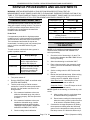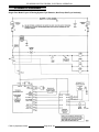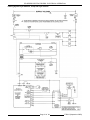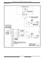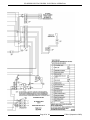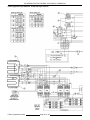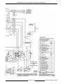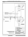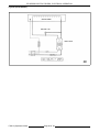
1
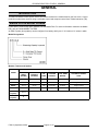
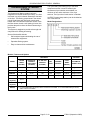
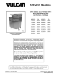
SERVICE MANUAL
ER SERIES ELECTRIC FRYERS
WITH TRIDELTA CONTROLS
MODEL
ML
ERD50
135541
ERD85
135543
ERC50
135545
ERC85
135547
ERD50F
135561
ERD85F
135563
ERC50F
135565
ERC85F
135567
ERO15
135548
ERO21
135549
ERC50 WITH DUAL BASKET
LIFTS SHOWN
- NOTICE This Manual is prepared for the use of trained Vulcan Service
Technicians and should not be used by those not properly
qualified. If you have attended a Vulcan Service School for this
product, you may be qualified to perform all the procedures
described in this manual.
This manual is not intended to be all encompassing. If you have
not attended a Vulcan Service School for this product, you should
read, in its entirety, the repair procedure you wish to perform to
determine if you have the necessary tools, instruments and skills
required to perform the procedure. Procedures for which you do
not have the necessary tools, instruments and skills should be
performed by a trained Vulcan Service Technician.
Reproduction or other use of this Manual, without the express
written consent of Vulcan, is prohibited.
For additional information on Vulcan-Hart Company or to locate an authorized parts
and service provider in your area, visit our website at www.vulcanhart.com.
A product of VULCAN-HART
LOUISVILLE, KY 40201-0696
F35613 (September 2003)
ER SERIES ELECTRIC FRYERS
TABLE OF CONTENTS
GENERAL . . . . . . . . . . . . . . . . . . . . . . . . . . . . . . . . . . . . . . . . . . . . . . . . . . . . . . . . . . . . . . . . . . . . . . . . . . . . . . . .
Introduction . . . . . . . . . . . . . . . . . . . . . . . . . . . . . . . . . . . . . . . . . . . . . . . . . . . . . . . . . . . . . . . . . . . . . . . . . . . .
Single Floor Model Fryers . . . . . . . . . . . . . . . . . . . . . . . . . . . . . . . . . . . . . . . . . . . . . . . . . . . . . . . . . . . . . . . . .
Model Designations . . . . . . . . . . . . . . . . . . . . . . . . . . . . . . . . . . . . . . . . . . . . . . . . . . . . . . . . . . . . . . . . .
Models, Features and Options . . . . . . . . . . . . . . . . . . . . . . . . . . . . . . . . . . . . . . . . . . . . . . . . . . . . . . . . .
Kleenscreen Filtering System . . . . . . . . . . . . . . . . . . . . . . . . . . . . . . . . . . . . . . . . . . . . . . . . . . . . . . . . . . . . . .
Model Designations . . . . . . . . . . . . . . . . . . . . . . . . . . . . . . . . . . . . . . . . . . . . . . . . . . . . . . . . . . . . . . . . .
Models, Features and Options . . . . . . . . . . . . . . . . . . . . . . . . . . . . . . . . . . . . . . . . . . . . . . . . . . . . . . . . .
Specifications . . . . . . . . . . . . . . . . . . . . . . . . . . . . . . . . . . . . . . . . . . . . . . . . . . . . . . . . . . . . . . . . . . . . . . . . . .
Tools . . . . . . . . . . . . . . . . . . . . . . . . . . . . . . . . . . . . . . . . . . . . . . . . . . . . . . . . . . . . . . . . . . . . . . . . . . . . . . . . .
Control Panels . . . . . . . . . . . . . . . . . . . . . . . . . . . . . . . . . . . . . . . . . . . . . . . . . . . . . . . . . . . . . . . . . . . . . . . . .
4
4
4
4
4
5
5
5
6
6
7
REMOVAL AND REPLACEMENT OF PARTS . . . . . . . . . . . . . . . . . . . . . . . . . . . . . . . . . . . . . . . . . . . . . . . . . . . . 8
Covers and Panels . . . . . . . . . . . . . . . . . . . . . . . . . . . . . . . . . . . . . . . . . . . . . . . . . . . . . . . . . . . . . . . . . . . . . . 8
Cooking Controls . . . . . . . . . . . . . . . . . . . . . . . . . . . . . . . . . . . . . . . . . . . . . . . . . . . . . . . . . . . . . . . . . . . . . . . 9
Filter Valve and Discard Valve Switches . . . . . . . . . . . . . . . . . . . . . . . . . . . . . . . . . . . . . . . . . . . . . . . . . . . . 10
Temperature Probe . . . . . . . . . . . . . . . . . . . . . . . . . . . . . . . . . . . . . . . . . . . . . . . . . . . . . . . . . . . . . . . . . . . . 10
High Limit Thermostat . . . . . . . . . . . . . . . . . . . . . . . . . . . . . . . . . . . . . . . . . . . . . . . . . . . . . . . . . . . . . . . . . . 11
Power Supply Box Components . . . . . . . . . . . . . . . . . . . . . . . . . . . . . . . . . . . . . . . . . . . . . . . . . . . . . . . . . . . 12
Heating Elements . . . . . . . . . . . . . . . . . . . . . . . . . . . . . . . . . . . . . . . . . . . . . . . . . . . . . . . . . . . . . . . . . . . . . . 12
Lift Assist Springs . . . . . . . . . . . . . . . . . . . . . . . . . . . . . . . . . . . . . . . . . . . . . . . . . . . . . . . . . . . . . . . . . . . . . . 13
Tilt Switch . . . . . . . . . . . . . . . . . . . . . . . . . . . . . . . . . . . . . . . . . . . . . . . . . . . . . . . . . . . . . . . . . . . . . . . . . . . . 14
Basket Lift Tube . . . . . . . . . . . . . . . . . . . . . . . . . . . . . . . . . . . . . . . . . . . . . . . . . . . . . . . . . . . . . . . . . . . . . . . 15
Basket Lift Motor . . . . . . . . . . . . . . . . . . . . . . . . . . . . . . . . . . . . . . . . . . . . . . . . . . . . . . . . . . . . . . . . . . . . . . . 15
Basket Lift Cam Switch . . . . . . . . . . . . . . . . . . . . . . . . . . . . . . . . . . . . . . . . . . . . . . . . . . . . . . . . . . . . . . . . . . 16
Pump and Motor . . . . . . . . . . . . . . . . . . . . . . . . . . . . . . . . . . . . . . . . . . . . . . . . . . . . . . . . . . . . . . . . . . . . . . . 16
SERVICE PROCEDURES AND ADJUSTMENTS . . . . . . . . . . . . . . . . . . . . . . . . . . . . . . . . . . . . . . . . . . . . . . . . .
Temperature Probe Test . . . . . . . . . . . . . . . . . . . . . . . . . . . . . . . . . . . . . . . . . . . . . . . . . . . . . . . . . . . . . . . .
Cooking Control Calibration . . . . . . . . . . . . . . . . . . . . . . . . . . . . . . . . . . . . . . . . . . . . . . . . . . . . . . . . . . . . . .
Lift Assist Spring Adjustment . . . . . . . . . . . . . . . . . . . . . . . . . . . . . . . . . . . . . . . . . . . . . . . . . . . . . . . . . . . . .
Basket Lift Arm Adjustment . . . . . . . . . . . . . . . . . . . . . . . . . . . . . . . . . . . . . . . . . . . . . . . . . . . . . . . . . . . . . .
Heating Element Test . . . . . . . . . . . . . . . . . . . . . . . . . . . . . . . . . . . . . . . . . . . . . . . . . . . . . . . . . . . . . . . . . . .
Solid State Control . . . . . . . . . . . . . . . . . . . . . . . . . . . . . . . . . . . . . . . . . . . . . . . . . . . . . . . . . . . . . . . . . . . . .
Operation . . . . . . . . . . . . . . . . . . . . . . . . . . . . . . . . . . . . . . . . . . . . . . . . . . . . . . . . . . . . . . . . . . . . . . . .
Error Messages . . . . . . . . . . . . . . . . . . . . . . . . . . . . . . . . . . . . . . . . . . . . . . . . . . . . . . . . . . . . . . . . . . .
Programming . . . . . . . . . . . . . . . . . . . . . . . . . . . . . . . . . . . . . . . . . . . . . . . . . . . . . . . . . . . . . . . . . . . . .
Computer Control . . . . . . . . . . . . . . . . . . . . . . . . . . . . . . . . . . . . . . . . . . . . . . . . . . . . . . . . . . . . . . . . . . . . . .
Operation . . . . . . . . . . . . . . . . . . . . . . . . . . . . . . . . . . . . . . . . . . . . . . . . . . . . . . . . . . . . . . . . . . . . . . . .
Service Programming . . . . . . . . . . . . . . . . . . . . . . . . . . . . . . . . . . . . . . . . . . . . . . . . . . . . . . . . . . . . . . .
Error messages . . . . . . . . . . . . . . . . . . . . . . . . . . . . . . . . . . . . . . . . . . . . . . . . . . . . . . . . . . . . . . . . . . .
Enter Service Mode . . . . . . . . . . . . . . . . . . . . . . . . . . . . . . . . . . . . . . . . . . . . . . . . . . . . . . . . . . . . . . . .
Display, Led and Keypad Test . . . . . . . . . . . . . . . . . . . . . . . . . . . . . . . . . . . . . . . . . . . . . . . . . . . . . . . .
17
17
17
18
18
19
20
20
20
20
21
21
21
21
21
22
ELECTRICAL OPERATION . . . . . . . . . . . . . . . . . . . . . . . . . . . . . . . . . . . . . . . . . . . . . . . . . . . . . . . . . . . . . . . . . .
Component Function . . . . . . . . . . . . . . . . . . . . . . . . . . . . . . . . . . . . . . . . . . . . . . . . . . . . . . . . . . . . . . . . . . .
Component Location . . . . . . . . . . . . . . . . . . . . . . . . . . . . . . . . . . . . . . . . . . . . . . . . . . . . . . . . . . . . . . . . . . .
Power Supply Box . . . . . . . . . . . . . . . . . . . . . . . . . . . . . . . . . . . . . . . . . . . . . . . . . . . . . . . . . . . . . . . . . . . . .
Circuit Breaker/Supply Box . . . . . . . . . . . . . . . . . . . . . . . . . . . . . . . . . . . . . . . . . . . . . . . . . . . . . . . . . . . . . . .
23
23
24
25
26
F35613 (September 2003)
Page 2 of 48
ER SERIES ELECTRIC FRYERS
Sequence of Operation . . . . . . . . . . . . . . . . . . . . . . . . . . . . . . . . . . . . . . . . . . . . . . . . . . . . . . . . . . . . . . . . . .
Cooking Control, Solid State or Computer . . . . . . . . . . . . . . . . . . . . . . . . . . . . . . . . . . . . . . . . . . . . . . .
Filtering System . . . . . . . . . . . . . . . . . . . . . . . . . . . . . . . . . . . . . . . . . . . . . . . . . . . . . . . . . . . . . . . . . . .
Schematic Diagrams . . . . . . . . . . . . . . . . . . . . . . . . . . . . . . . . . . . . . . . . . . . . . . . . . . . . . . . . . . . . . . . . . . .
Single Floor Model Fryers & Filtering System Fryer Batteries, Non Pump Side Fryer Section(s) . . . . .
Filtering System Fryer Batteries, Pump Side Fryer Section . . . . . . . . . . . . . . . . . . . . . . . . . . . . . . . . . .
Heater Circuit . . . . . . . . . . . . . . . . . . . . . . . . . . . . . . . . . . . . . . . . . . . . . . . . . . . . . . . . . . . . . . . . . . . . .
Basket Lift Circuit . . . . . . . . . . . . . . . . . . . . . . . . . . . . . . . . . . . . . . . . . . . . . . . . . . . . . . . . . . . . . . . . . .
Wiring Diagrams . . . . . . . . . . . . . . . . . . . . . . . . . . . . . . . . . . . . . . . . . . . . . . . . . . . . . . . . . . . . . . . . . . . . . . .
Single Floor Model Fryers & Filtering System Fryer Batteries, Non Pump Side Fryer Section(s) . . . . .
Filtering System Fryer Batteries, Pump Side Fryer Section . . . . . . . . . . . . . . . . . . . . . . . . . . . . . . . . . .
Basket Lift . . . . . . . . . . . . . . . . . . . . . . . . . . . . . . . . . . . . . . . . . . . . . . . . . . . . . . . . . . . . . . . . . . . . . . . .
Filtering System Fryers, Filter/Discard Switch Connections . . . . . . . . . . . . . . . . . . . . . . . . . . . . . . . . . .
Frymate (Dump Station) . . . . . . . . . . . . . . . . . . . . . . . . . . . . . . . . . . . . . . . . . . . . . . . . . . . . . . . . . . . . .
27
27
28
30
30
31
32
33
34
34
36
38
39
40
TROUBLESHOOTING . . . . . . . . . . . . . . . . . . . . . . . . . . . . . . . . . . . . . . . . . . . . . . . . . . . . . . . . . . . . . . . . . . . . . .
All Models . . . . . . . . . . . . . . . . . . . . . . . . . . . . . . . . . . . . . . . . . . . . . . . . . . . . . . . . . . . . . . . . . . . . . . . . . . . .
Solid State Control . . . . . . . . . . . . . . . . . . . . . . . . . . . . . . . . . . . . . . . . . . . . . . . . . . . . . . . . . . . . . . . . . . . . .
Computer Control . . . . . . . . . . . . . . . . . . . . . . . . . . . . . . . . . . . . . . . . . . . . . . . . . . . . . . . . . . . . . . . . . . . . . .
Solid State or Computer Control Harness Pin-Outs . . . . . . . . . . . . . . . . . . . . . . . . . . . . . . . . . . . . . . . . . . . .
Control Interface Board Pin-Outs . . . . . . . . . . . . . . . . . . . . . . . . . . . . . . . . . . . . . . . . . . . . . . . . . . . . . . . . . .
Frymate (Dump Station) with Optional Heater . . . . . . . . . . . . . . . . . . . . . . . . . . . . . . . . . . . . . . . . . . . . . . . .
Kleenscreen Filtering System . . . . . . . . . . . . . . . . . . . . . . . . . . . . . . . . . . . . . . . . . . . . . . . . . . . . . . . . . . . . .
41
41
42
42
43
43
43
44
CONDENSED SPARE PARTS LIST . . . . . . . . . . . . . . . . . . . . . . . . . . . . . . . . . . . . . . . . . . . . . . . . . . . . . . . . . . . 48
© VULCAN 2003
Page 3 of 48
F35613 (September 2003)
ER SERIES ELECTRIC FRYERS - GENERAL
GENERAL
INTRODUCTION
This Service Manual covers specific service information related to the models listed on the front cover. Current
production model fryers are built using a solid state control and computer control from Tridelta Industries (TDI).
SINGLE FLOOR MODEL FRYERS
Fryers with the Filter-Ready option installed, use the Mobile Filter. For service information related to the Mobile
filter, refer to F24599 MOBILE FILTERS.
An ERO Frymate (dump station) can be configured in a battery with fryers 15 1/2 inches or 21 inches in width.
Model Designations
Models, Features and Options
FEATURES
OPTIONS
MODEL
FRYER
WIDTH
(INCHES)
SHORTENING
CAPACITY
(POUNDS)
FRY
TANK
COOKING
CONTROL
COOK TIMER
(MM:SS)
AUTOMATIC BASKET
LIFTS
ERD50
15 1/2
45-50
Full
Solid State
0-99:59
Single or Dual
ERD85
21
85-90
Full
Solid State
0-99:59
Single or Dual
ERC50
15 1/2
45-50
Full
Computer
0-99:59
Single or Dual
ERC85
21
85-90
Full
Computer
0-99:59
Single or Dual
ERO15
(Frymate)
15 1/2
ERO21
(Frymate)
21
F35613 (September 2003)
Page 4 of 48
ER SERIES ELECTRIC FRYERS - GENERAL
The fryer battery still utilizes many of the same
components as the Vulcan ER series fryers.
KLEENSCREEN FILTERING
SYSTEM
The Kleenscreen filtering system has been
integrated into the ER Series fryer battery. The filter
is housed in a pull-out drawer assembly at the base
of the fryer. The filtering components in the drawer
include a stainless steel filter tank, crumb-catch
basket and a dual element mesh filter screen. With
the filter drawer closed, a self-seating oil return line
provides the path to return the filtered shortening to
the fry tank.
Kleenscreen fryer batteries are available in a
minimum of two and a maximum of four fryer
sections. The fryer size of each section is identical.
An ERO Frymate (dump station) can be included as
one of the sections.
Model Designations
This system is designed to provide a thorough and
easy method for filtering shortening.
Some of the benefits include:
•
Self-contained system eliminating the use of
external filter equipment.
•
Paperless filtering system.
•
Easy to clean and low maintenance.
Models, Features and Options
FEATURES
OPTIONS
FRYER
WIDTH
(INCHES)
FRYING OIL
CAPACITY
PER FRYER
(POUNDS)
FILTER PAN
CAPACITY
(POUNDS)
FRY
TANK
COOKING
CONTROL
COOK
TIMER
(MM:SS)
AUTOMATIC
BASKET LIFTS
2ERD50F 1
42
45-50
130
Full
Solid State
0-99:59
Single or Dual
2
42
85-90
130
Full
Solid State
0-99:59
Single or Dual
2ERC50F 1
31
45-50
130
Full
Computer
0-99:59
Single or Dual
2
42
85-90
130
Full
Computer
0-99:59
Single or Dual
MODEL
2ERD85F
2ERC85F
ERO15
(Frymate)
15 1/2
ERO21
(Frymate)
21
NOTES:
1. For each additional fryer section, add 15 1/2 inches to the width. 2. For each additional fryer section,
add 21 inches to the width.
Page 5 of 48
F35613 (September 2003)
ER SERIES ELECTRIC FRYERS - GENERAL
SPECIFICATIONS
TOOLS
Standard
MODEL
KW
PER FRYER
SECTION 2
AMPS - EACH FRYER
SECTION
(3 PHASE/ 60HZ) 1
208V
240V
480V
14
39
34
17
ERD50F
17
47
41
20
24
67
58
29
ERC50,
14
39
34
17
ERC50F
17
47
41
20
24
67
58
29
ERD85F
ERC85,
ERC85F
NOTES:
1.
2.
Standard set of hand tools.
•
VOM with AC current tester.
NOTE: Any quality VOM with a sensitivity of
20,000 ohms per volt can be used.
PER LINE
ERD50,
ERD85,
•
•
Special
•
Field service grounding kit P/N TL- 84919.
•
Loctite 242 P/N 520228 or equivalent.
•
Burndy pin extraction tool RX2025 GE1;
Newark Electronics Catalog Number 16F6666.
Used for removing pin terminals on Burndy
connectors.
Amperage values in the table are
nominal. Tolerance is +5/-10%.
14kw is standard on all fryers except
85 lb. models which are 24kw.
Single Floor Model Fryers
•
Fryers with the Filter-Ready option installed,
use a 120VAC power cord for the Mobile Filter.
•
208VAC, 240VAC or 480VAC (3 phase, 60HZ)
to power the heating elements.
Kleenscreen Filtering System
Separate electrical connections are required for
each section of the battery.
•
208VAC, 240VAC or 480VAC (3 phase, 60HZ)
to power the heating elements.
•
On 208VAC and 240VAC models, a
transformer provides power for the fryer
controls, basket lift(s) if installed, and
Kleenscreen filtering controls.
•
On 480VAC models, a 120VAC connection is
required for each fryer section.
•
All models require a separate 120VAC
connection for the pump motor (5.0 amp draw).
F35613 (September 2003)
Temperature tester (thermocouple type).
Page 6 of 48
ER SERIES ELECTRIC FRYERS - GENERAL
CONTROL PANELS
Solid State
!
Five product/programming keys: Left basket (up arrow); Right basket (down arrow); Temperature; Program
and Boil.
!
Four digit display window that indicates fryer status, time left to cook, and actual or set point temperature.
Decimal point of first character indicates heat on when lit.
!
Two LED lamps that illuminate when a basket timer is being programmed or blink to when a timer is
activated (left or right basket).
!
Boil key for automatic or manual mode BOIL out cleaning of fry tank.
SOLID STATE CONTROL, D MODEL
Computer
!
Eighteen product/programming keys allow individual product cooking times for up to ten different products:
Product/Programming keys 1 thru 0; Oil Temp to view actual temperature or set the desired product cooking
temperature; L & R (Left & Right) basket selection; Toggle; Boil; and two Timer keys.
Left & Right Arrows - used to initiate programming of time and checking stored values (left 1-5 & right 6-0).
!
Left & Right displays that indicate actual or set point temperature, remaining times, operating mode, and
completion of preheat period.
!
Two LED lamps on the OIL TEMP key that indicate heat on and ten individual LED lamps above each of the
ten product/programming keys: LED’s blink when a product key is activated, solid when using a key for
programming.
!
Boil key for automatic or manual mode BOIL out cleaning of fry tank.
COMPUTER CONTROL, C MODEL
Page 7 of 48
F35613 (September 2003)
ER SERIES ELECTRIC FRYERS - REMOVAL AND REPLACEMENT OF PARTS
REMOVAL AND REPLACEMENT OF PARTS
COVERS AND PANELS
WARNING: DISCONNECT THE
ELECTRICAL POWER TO THE
MACHINE AND FOLLOW LOCKOUT
/ TAGOUT PROCEDURES. THERE
MAY BE MULTIPLE CIRCUITS. BE
SURE ALL CIRCUITS ARE
DISCONNECTED.
Control Panel
1.
Remove screws at top of control panel and
lower panel.
2.
Disconnect wiring harness then remove control
panel.
3.
Reverse procedure to install.
4.
Remove screws from the bottom of element
head assembly.
5.
Grasp heating elements and remove 2x4
lumber. Lift the elements and pull toward rear
of fryer. Head cover will separate from element
head base.
Element Head Cover
1.
Remove basket hanger or lift arm(s) if basket
lift option is installed.
2.
Remove screws from rear of element head
assembly.
A.
Lower the heating elements and place
them in fry tank.
NOTE: Heating elements remain attached to
element head cover.
6.
Reverse procedure to install.
Basket Lift Covers
NOTE: Applies to fryers with basket lift option only.
3.
Raise heating elements and place 2x4 lumber
under them for support.
F35613 (September 2003)
1.
Access rear of fryer.
2.
Remove basket lift arms from lift tubes.
3.
Remove screws securing upper cover to fryer.
Page 8 of 48
ER SERIES ELECTRIC FRYERS - REMOVAL AND REPLACEMENT OF PARTS
NOTE: The cover is flanged at the top & bottom and
is held in place by an interference fit. The bottom
flange is formed to secure the cover to fryer.
4.
Reverse procedure to install.
COOKING CONTROLS
WARNING: DISCONNECT THE
ELECTRICAL POWER TO THE
MACHINE AND FOLLOW LOCKOUT
/ TAGOUT PROCEDURES. THERE
MAY BE MULTIPLE CIRCUITS. BE
SURE ALL CIRCUITS ARE
DISCONNECTED.
A.
4.
5.
Lift the upper cover over support rods to
remove.
Remove screws securing lower cover to motor
mounting base.
CAUTION: Certain components in this system
are subject to damage by electrostatic discharge
during field repairs. A field service ground kit is
available to prevent damage. The field service
grounding kit must be used anytime the control
board is handled.
1.
Remove the control panel as outlined under
CONTROL PANEL.
2.
Remove cooking control by removing mounting
nuts securing the control and mounting panel
to front control panel.
Reverse procedure to install.
Rear Door (Access Cover)
1.
Access rear of fryer.
2.
Remove basket lift covers if basket lift option is
installed.
3.
Remove access cover at the top.
Page 9 of 48
F35613 (September 2003)
ER SERIES ELECTRIC FRYERS - REMOVAL AND REPLACEMENT OF PARTS
3.
Lift the cooking control with mounting panel
attached, off the front control panel.
Remove switch cover and disconnect lead
wires from switch.
5.
Reverse procedure to install and check for
proper operation.
NOTE: Switches are not adjustable.
4.
Reverse procedure to install.
5.
Re-connect power and turn power switch on.
6.
Program the cooking control for the control
type as outlined under SOLID STATE
CONTROL or COMPUTER CONTROL in
SERVICE PROCEDURES AND
ADJUSTMENTS.
NOTE: If installing a replacement cooking control,
program the control with the customers settings and
products.
7.
4.
Check for proper operation.
FILTER VALVE AND DISCARD
VALVE SWITCHES
TEMPERATURE PROBE
WARNING: DISCONNECT THE
ELECTRICAL POWER TO THE
MACHINE AND FOLLOW LOCKOUT
/ TAGOUT PROCEDURES. THERE
MAY BE MULTIPLE CIRCUITS. BE
SURE ALL CIRCUITS ARE
DISCONNECTED.
CAUTION: Do not sharply bend and kink the
temperature probe or damage may occur.
1.
Raise heating elements.
2.
Remove clamps from temperature probe.
3.
Remove element head cover as outlined under
COVERS AND PANELS.
4.
Disconnect temperature probe lead wires.
WARNING: DISCONNECT THE
ELECTRICAL POWER TO THE
MACHINE AND FOLLOW LOCKOUT
/ TAGOUT PROCEDURES. THERE
MAY BE MULTIPLE CIRCUITS. BE
SURE ALL CIRCUITS ARE
DISCONNECTED.
1.
Open the door to the fryer section being
serviced.
2.
Disconnect lead wire connector (2 pin) to the
switch.
3.
Remove switch mounting screws.
F35613 (September 2003)
Page 10 of 48
ER SERIES ELECTRIC FRYERS - REMOVAL AND REPLACEMENT OF PARTS
5.
Remove temperature probe from the element
head.
6.
Reverse procedure to install.
3.
Remove element head cover as outlined under
COVERS AND PANELS.
4.
Remove high limit from mounting bracket.
5.
Disconnect high limit lead wires.
6.
Remove grommet from the element head
assembly.
7.
Remove the bulb, capillary tube and high limit
from the element head assembly.
NOTE: When installing, ensure grommet remains in
place when inserting temperature probe thru the
grommet in the element head.
7.
Check cooking control calibration as outlined in
COOKING CONTROL CALIBRATION under
SERVICE PROCEDURES AND
ADJUSTMENTS.
HIGH LIMIT THERMOSTAT
WARNING: DISCONNECT THE
ELECTRICAL POWER TO THE
MACHINE AND FOLLOW LOCKOUT
/ TAGOUT PROCEDURES. THERE
MAY BE MULTIPLE CIRCUITS. BE
SURE ALL CIRCUITS ARE
DISCONNECTED.
CAUTION: Do not sharply bend and kink the
capillary tube or damage may occur.
1.
Raise heating elements.
2.
Loosen clamps securing capillary tube and
bulb to element.
NOTE: When installing, slide grommet onto
capillary tube then insert grommet into the capillary
tube thru hole in the element head.
8.
Page 11 of 48
Reverse procedure to install.
F35613 (September 2003)
ER SERIES ELECTRIC FRYERS - REMOVAL AND REPLACEMENT OF PARTS
POWER SUPPLY BOX
COMPONENTS
WARNING: DISCONNECT THE
ELECTRICAL POWER TO THE
MACHINE AND FOLLOW LOCKOUT
/ TAGOUT PROCEDURES. THERE
MAY BE MULTIPLE CIRCUITS. BE
SURE ALL CIRCUITS ARE
DISCONNECTED.
CAUTION: Certain components in this system
are subject to damage by electrostatic discharge
during field repairs. A field service grounding kit
is available to prevent damage. The field service
grounding kit must be used anytime a control
board is handled.
1.
Remove the control panel as outlined under
CONTROL PANEL.
2.
Disconnect lead wires then remove the
component being replaced.
5.
Reverse procedure to install the replacement
component and check for proper operation.
HEATING ELEMENTS
WARNING: DISCONNECT THE
ELECTRICAL POWER TO THE
MACHINE AND FOLLOW LOCKOUT
/ TAGOUT PROCEDURES. THERE
MAY BE MULTIPLE CIRCUITS. BE
SURE ALL CIRCUITS ARE
DISCONNECTED.
CAUTION: Do not sharply bend and kink the
capillary tube or the temperature probe, or
damage may occur.
A.
3.
Remove basket hanger or lift arm(s) if basket
lift option is installed.
2.
Raise heating elements.
If removing, contactor(s), transformer, or
filter relay, continue with procedure.
A.
If replacing left heating element, loosen
high limit bulb and capillary tube clamps.
Remove high limit bulb and capillary tube
from clamps then position away from
element.
B.
If replacing right heating element, remove
temperature probe clamps and position
temperature probe away from element.
Remove screw securing control plate to box.
A.
4.
1.
Grasp control plate on the right side at the
top, and pull out until left side holding tab
clears slot.
Disconnect lead wires then remove the
component being replaced.
F35613 (September 2003)
Page 12 of 48
ER SERIES ELECTRIC FRYERS - REMOVAL AND REPLACEMENT OF PARTS
6.
Remove screws from heating element
mounting bracket and remove heating element.
7.
Reverse procedure to install.
LIFT ASSIST SPRINGS
WARNING: DISCONNECT THE
ELECTRICAL POWER TO THE
MACHINE AND FOLLOW LOCKOUT
/ TAGOUT PROCEDURES. THERE
MAY BE MULTIPLE CIRCUITS. BE
SURE ALL CIRCUITS ARE
DISCONNECTED.
NOTE: When installing high limit, route the capillary
tube and center the bulb between the clamps before
tightening.
3.
Remove element assembly clamps. Front
clamps stiffen and secure both elements
together. Rear clamps stiffen each individual
element.
4.
Remove element head cover as outlined under
COVERS AND PANELS.
5.
Disconnect heating element lead wires.
1.
Remove rear door (access cover) as outlined
under COVERS AND PANELS.
2.
Raise heating elements and place 2x4 lumber
under them for support. Heating elements are
to remain upright.
3.
Loosen all eye bolt mounting nuts to release
tension on springs.
NOTE: Each heating element assembly contains
three individual elements (six lead wire connections
total).
Page 13 of 48
F35613 (September 2003)
ER SERIES ELECTRIC FRYERS - REMOVAL AND REPLACEMENT OF PARTS
TILT SWITCH
WARNING: DISCONNECT THE
ELECTRICAL POWER TO THE
MACHINE AND FOLLOW LOCKOUT
/ TAGOUT PROCEDURES. THERE
MAY BE MULTIPLE CIRCUITS. BE
SURE ALL CIRCUITS ARE
DISCONNECTED.
4.
Remove lift assist springs from the eye bolt
hooks.
5.
Remove lift assist springs from the hangers.
6.
To install springs:
A.
Attach spring hook to hanger thru rear
door opening.
B.
Attach spring hook to eye bolt and tighten
eye bolt mounting nut.
1.
Remove element head cover as outlined under
COVERS AND PANELS.
2.
Lower heating elements.
3.
Disconnect lead wires from tilt switch.
4.
Remove tilt switch from element head.
REAR VIEW SHOWN, ELEMENTS LOWERED
C.
7.
FRONT VIEW SHOWN, ELEMENTS RAISED
Remove 2x4 lumber and lower heating
elements.
Adjust spring tension as outlined under LIFT
ASSIST SPRING ADJUSTMENT in SERVICE
PROCEDURES AND ADJUSTMENTS.
F35613 (September 2003)
5.
Reverse procedure to install and check for
proper operation.
NOTE: The tilt switch and magnet are mounted in
fixed locations and are not adjustable.
Page 14 of 48
ER SERIES ELECTRIC FRYERS - REMOVAL AND REPLACEMENT OF PARTS
BASKET LIFT TUBE
BASKET LIFT MOTOR
WARNING: DISCONNECT THE
ELECTRICAL POWER TO THE
MACHINE AND FOLLOW LOCKOUT
/ TAGOUT PROCEDURES. THERE
MAY BE MULTIPLE CIRCUITS. BE
SURE ALL CIRCUITS ARE
DISCONNECTED.
WARNING: DISCONNECT THE
ELECTRICAL POWER TO THE
MACHINE AND FOLLOW LOCKOUT
/ TAGOUT PROCEDURES. THERE
MAY BE MULTIPLE CIRCUITS. BE
SURE ALL CIRCUITS ARE
DISCONNECTED.
1.
Remove basket lift covers as outlined under
COVERS AND PANELS.
1.
Remove basket lift tube as outlined under
BASKET LIFT TUBE.
2.
Remove nut securing lift bar to the lift tube.
2.
3.
Remove screws securing lift tube bracket to
fryer then remove bracket and lift tube.
Disconnect lead wires from cam switch and
basket lift motor.
3.
Loosen set screws securing crank arm
assembly to the basket lift motor shaft.
4.
Remove screws securing motor mounting plate
to fryer then remove motor from plate.
4.
Reverse procedure to install.
Page 15 of 48
F35613 (September 2003)
ER SERIES ELECTRIC FRYERS - REMOVAL AND REPLACEMENT OF PARTS
5.
Reverse procedure to install and check for
proper operation.
PUMP AND MOTOR
NOTE: When installing, keep all lead wires clear
from moving parts.
WARNING: DISCONNECT THE
ELECTRICAL POWER TO THE
MACHINE AND FOLLOW LOCKOUT
/ TAGOUT PROCEDURES. THERE
MAY BE MULTIPLE CIRCUITS. BE
SURE ALL CIRCUITS ARE
DISCONNECTED.
BASKET LIFT CAM SWITCH
WARNING: DISCONNECT THE
ELECTRICAL POWER TO THE
MACHINE AND FOLLOW LOCKOUT
/ TAGOUT PROCEDURES. THERE
MAY BE MULTIPLE CIRCUITS. BE
SURE ALL CIRCUITS ARE
DISCONNECTED.
1.
Open both fryer cabinet doors above the filter
tank drawer.
2.
Pull the filter drawer out and remove splash
guard/cover from tank.
A.
1.
Remove basket lift covers as outlined under
COVERS AND PANELS.
2.
Disconnect lead wires from cam switch.
3.
Remove screws securing cam switch to motor
mounting plate.
3.
If filter tank is not empty, remove
shortening from filter tank.
Remove the filter tank assembly and push the
tank support arms back underneath the fryer.
NOTE: The remaining steps are written for front
removal of the pump assembly. If access to the
back of the fryer is available, it may be easier to
remove the pump from the rear.
4.
Disconnect the electrical connection to the
motor.
5.
Separate the swivel hose connections at the
pump.
NOTE: When viewed from pump end, the right side
is the intake port and the left side is the discharge
port.
6.
Remove motor mounting bolts.
7.
Remove the motor and pump (pipe fittings
attached) from the fryer.
A.
8.
4.
Reverse procedure to install.
NOTE: Ensure the rubber vibration pad or the
grommets are installed under the motor mounting
plate.
Reverse procedure to install and check for
proper operation.
NOTE: When installing, place the cam switch block
behind the cam switch for proper spacing.
F35613 (September 2003)
If replacing the pump and motor, remove
the existing pipe assemblies and reuse.
Page 16 of 48
ER SERIES ELECTRIC FRYERS - SERVICE PROCEDURES AND ADJUSTMENTS
SERVICE PROCEDURES AND ADJUSTMENTS
WARNING: CERTAIN PROCEDURES IN THIS SECTION REQUIRE ELECTRICAL TEST OR
MEASUREMENTS WHILE POWER IS APPLIED TO THE MACHINE. EXERCISE EXTREME CAUTION AT ALL
TIMES. IF TEST POINTS ARE NOT EASILY ACCESSIBLE, DISCONNECT POWER AND FOLLOW LOCKOUT
/ TAGOUT PROCEDURES, ATTACH TEST EQUIPMENT AND REAPPLY POWER TO TEST.
TEMPERATURE PROBE TEST
Temperature (ºF)
Resistance (S)
77
90,000 - 110,000
The temperature probe is used for both the solid
state and computer cooking controls. The probe is
an RTD (resistance temperature detector) of the
thermistor type. As temperature increases the
resistance value decreases.
Probe Fault
If a temperature probe fault or high temperature
condition occurs, a fault message will be displayed
and the electronic alarm will sound continuously.
The heat demand and basket lift outputs are
de-activated. If a cooking cycle is in process (timer
active), it will be cancelled and the key pad
disabled.
SOLID STATE
COMPUTER
604 - 836
415
1
302 - 369
460
2
191 - 233
NOTE: 1. High temperature alarm level for the
cooking controls.
2. Shorted probe equivalent temperature.
COOKING CONTROL
CALIBRATION
NOTE: Verify condition of temperature probe as
outlined under TEMPERATURE PROBE TEST
before proceeding.
This will continue until the fault clears, power is
cycled or problem resolved.
Cooking
Control
350
Display Message
1.
An open will display Prob and a
short or high temperature
condition will display HI.
Check the level of shortening in fry tank. The
level must be between the MIN & MAX fill lines
before proceeding.
2.
Allow the shortening to cool below 300°F.
3.
Place a thermocouple in the geometric center
of the fry tank one inch below the shortening
surface.
4.
Set the cooking control to 350°F and turn the
fryer on.
5.
An open will display PROBE
OPEN and a short or high
temperature condition will
display PROBE SHORT.
1.
Turn power switch off.
Monitor the heat indicator lamp. When cooking
control is calling for heat, lamp will be on. If
cooking control is satisfied, lamp will be off.
2.
Remove CONTROL PANEL as outlined under
COVERS AND PANELS.
Solid State Control - Decimal point of first
character indicates heat on when lit.
3.
Test the probe using a VOM to measure
resistance. Connect the meter probe leads to
pins 3 & 4 on the female connector for the
wiring harness.
Computer Control - Two LED lamps on the oil
temp key that indicate heat on.
To Check:
A.
If the measured resistance values are
within the allowable range, the probe is
functioning properly. Reverse procedure
to install.
B.
If the measured resistance values are
outside the allowable range, install a
replacement probe as outlined under
TEMPERATURE PROBE in REMOVAL
AND REPLACEMENT OF PARTS.
C.
NOTE: Agitate the shortening, to eliminate any cold
zones.
6.
Check cooking control calibration.
Page 17 of 48
A.
Allow cooking control to cycle three times
to stabilize shortening temperature.
B.
Record meter reading from thermocouple
when the cooking control cycles off and on
for at least two complete heating cycles.
Calculate the average temperature by adding
the temperature reading when the heat lamp
goes out to the temperature reading when the
heat lamp comes on & divide this answer by 2.
F35613 (September 2003)
ER SERIES ELECTRIC FRYERS - SERVICE PROCEDURES AND ADJUSTMENTS
[ Temp. (Lamp off) + Temp. (lamp on) ] ÷ 2 = Average Temp.
Example: 360/ + 340/ ÷ 2 = 350/F.
The average temperature should be
350°F (± 5°F).
A.
If the average temperature reading is
within tolerance, cooking control is
properly calibrated.
B.
If the average temperature reading is out
of tolerance, perform the following:
1)
2)
Solid State Control - Adjust the offset
temperature accordingly as outlined
in SOLID STATE CONTROL under
SERVICE PROCEDURES and
ADJUSTMENTS.
B.
Adjust eye bolt mounting nuts as
necessary, but equally on all springs to
achieve the best spring tension to hold
elements in place.
Computer Control - Adjust the offset
temperature accordingly as outlined
in COMPUTER CONTROL under
SERVICE PROCEDURES and
ADJUSTMENTS.
7.
Repeat the average temperature calculation for
up to three attempts. Allow the cooking control
to cycle at least two times between
adjustments before performing the calculation.
8.
If calibration is unsuccessful, the cooking
control may be malfunctioning and cannot be
adjusted properly. Install a replacement
cooking control and check calibration.
LIFT ASSIST SPRING
ADJUSTMENT
1.
Turn power switch off.
C.
Perform spring tension check.
2.
Remove lift arm(s) if basket lift option is
installed.
D.
Repeat spring tension adjustment if
necessary.
3.
Check spring tension:
E.
Tighten stop nut on all eye bolts.
4.
5.
A.
Raise heating elements to the full up
position. Elements should remain in place.
B.
Lower heating elements to the full down
position. Elements should remain in place.
C.
If the elements remain in place as
described, then no adjustment is
necessary. If the elements do not remain
in place, continue with procedure for
adjustment.
Remove basket lift tube(s) if basket lift option is
installed as outlined under BASKET LIFT
TUBE in REMOVAL AND REPLACEMENT OF
PARTS.
Remove rear door (access cover).
NOTE: Elements should be in the down position.
6.
7.
BASKET LIFT ARM
ADJUSTMENT
1.
2.
Turn power switch on and set temperature to
350/F. Allow the shortening to reach set
temperature.
3.
Check basket lift operation.
Loosen stop nut on all eye bolts.
F35613 (September 2003)
With shortening at room temperature, verify the
level is between MIN & MAX lines in fry tank.
Add shortening as needed.
NOTE: Shortening will expand when heated. Do not
fill the fry tank past the MAX line.
To adjust spring tension:
A.
Replace rear door (access cover) and basket
lift components (if installed).
Page 18 of 48
ER SERIES ELECTRIC FRYERS - SERVICE PROCEDURES AND ADJUSTMENTS
A.
4.
If necessary, adjust as outlined below.
1.
Remove element head cover as outlined under
COVERS AND PANELS in REMOVAL AND
REPLACEMENT OF PARTS.
When basket is in the up position, the bottom
of the basket should be out of the shortening.
When basket is in the down position, the
bottom of the basket should clear the crumb
screen and the product should be submerged.
CAUTION: Heating elements must remain
submerged in shortening while performing this
test or damage may occur.
A.
To adjust, remove basket arm from lift
shaft, loosen stop nut and turn height
adjustment bolt to raise or lower basket
arm as required. Both baskets should be
same height.
2.
Access heating element lead wire connections
at wire nuts.
3.
Re-connect power, turn power switch on and
set cooking control to call for heat.
Re-tighten stop nut when complete.
4.
Measure voltage at heating element
connections and verify against data plate
voltage.
B.
NOTE: If adjustment is to low, when the basket is
lowered, it will disengage from basket arm.
A.
If voltage is incorrect, see ALL MODELS
under TROUBLESHOOTING.
B.
If voltage is correct, check current draw
(amps) through the heating element lead
wires. See table for proper values.
NOTE: This method is preferred over a
resistance check when a clamp on type amp
meter is available.
1)
If current draw is correct then heating
element is functioning properly.
2)
If current draw is not correct, turn
power switch off and disconnect
power to the machine.
HEATING ELEMENT TEST
VOLTAGE
208
240
480
NOTES:
C.
a.
Install a replacement heating
element.
b.
Proceed to last step.
TOTAL
KW
AMPS PER
ELEMENT
OHMS PER
ELEMENT
14
39
18.3
If unable to check current draw, a
resistance check may indicate a
malfunctioning element. See table for
proper values.
17
47
15.2
1)
24
67
10.7
Turn power switch off and disconnect
power to the machine.
14
34
24.2
2)
17
41
20.4
Remove wire nuts from heating
element lead wire connections and
separate lead wires.
24
58
14.2
3)
Check resistance (ohms).
14
17
97.6
17
20
83.0
24
29
57.4
5.
Check for proper operation.
1. Values in the table are nominal.
Tolerance is +5/-10%.
2. Voltage values are @ 60HZ.
3. Resistance values (ohms) are @ room
temperature.
Page 19 of 48
F35613 (September 2003)
ER SERIES ELECTRIC FRYERS - SERVICE PROCEDURES AND ADJUSTMENTS
Use the following key sequence (password) to
enter PROGRAM MODE: LEFT BASKET/UP;
LEFT BASKET/UP; RIGHT BASKET/DOWN;
RIGHT BASKET/DOWN.
SOLID STATE CONTROL
Operation
Refer to the Installation & Operations manual for
specific operating instructions.
Error messages
For information on solid state control error
messages, refer to SOLID STATE CONTROL under
TROUBLESHOOTING.
Programming
2.
The solid state control’s programming mode is used
to set the controls operational parameters.
NOTE: If a product key is active (timing),
programming mode can not be entered.
1.
3.
4.
Press V key to enter programming mode.
NOTE: If the proper key sequence is not
entered within 6 seconds the control exits
PROGRAM MODE.
Beeper chirp’s on each successful keypress; If
a key is not pressed within 2 minutes, the
control will automatically exit programming.
To scroll through each of the PROGRAM
ITEMS, press V and release.
To exit PROGRAM MODE, at any time, press
V and hold for 1 second.
If the PARAMETER LOCK feature is disabled,
PROGRAM MODE entry is immediate. If the
PARAMETER LOCK feature is enabled LoC
will be displayed.
PROGRAM
ITEM
Left Timer
Right Timer
KEY SEQUENCE
• Press Left Basket to increase or Right Basket to
decrease cook time. 1
• Press Left Basket to increase or Right Basket to
decrease cook time. 1
Set point
Temperature
• Press Left Basket to increase or Right Basket to
decrease set point temperature. 2
Calibration
Offset
• Press Left Basket to increase or Right Basket to
decrease offset temperature. 2, 3
DISPLAY 5
LED above left basket is on.
15:00 time value with flashing colon (MM:SS).
LED above right basket is on.
15:00 time value with flashing colon (MM:SS).
340F or 171C
current set point with flashing F or C
00F OR -00F
always in /F
CY L
Melt Options
• Press Left Basket or Right Basket to scroll thru
Melt Options.
CY L = Liquid
CY S = Solid
CY 0 = No
Energy Source
• Press Left Basket or Right Basket to select the
fryer<s energy source, electric or gas heat.
Parameter
Lock
• Press Left Basket or Right Basket to select
desired Parameter Lock Condition. 4
Degrees
F or C
• Press Left Basket or Right Basket to select
desired Temperature Scale.
NOTES:
1.
2.
3.
4.
5.
ELEC or gAS
Uloc or LoC
selected parameter is enabled if flashing
F or C
Time will change in one second increments, accelerating if the button is held.
Temperature will change in one degree increments, accelerating if the button is held.
Range -20 to +20, default = 0 (/F).
Selecting Parameter Lock enabled will take effect on the next Program Mode entry.
Default value shown in bold.
F35613 (September 2003)
Page 20 of 48
ER SERIES ELECTRIC FRYERS - SERVICE PROCEDURES AND ADJUSTMENTS
COMPUTER CONTROL
Operation
Refer to the Installation & Operations manual for specific operating instructions.
Service Programming
The computer control’s service programming mode is used to perform system diagnostic tests or edit program
items that affect the fryers operation.
NOTE: If a product key is active (timing), service programming can not be entered.
Error messages
For information on computer control error messages, refer to COMPUTER CONTROL under
TROUBLESHOOTING.
Enter Service Mode
1.
Press V key and enter password (default, 1972); Use product key numbers (1 thru 0) to enter values.
A.
SERVICE is displayed in left window & the LED’s above product key’s 1, 2, 4, 5, 6, 7 & 8 come on.
B.
Beeper chirp’s on each successful keypress; If a key is not pressed within 2 minutes, the computer will
automatically exit service programming (except in diagnostic mode).
2.
To exit a PROGRAM ITEM after making a selection, press V to accept and return to service programming.
3.
To exit SERVICE PROGRAMMING and return to operation mode, press V key twice.
PROGRAM
ITEM
Temperature
Offset
LED
STATUS
KEY SEQUENCE
ON
• Press 1 and enter desired offset temperature
OFF
LEFT
RIGHT
all
OFF 00 F
DEGREES
POSITIVE OR
NEGATIVE
DEGREES
MLTON:04
MELT ON
MLTOFF:11
MELT OFF
• Press V to accept selection
• Press TOGGLE to display direction of offset
(positive or negative)
Melt Cycle
On/Off Times
Diagnostic
Mode
• Press 2 and set melt cycle on time 7
all
• Press LEFT OR RIGHT TIMER key arrow
and set melt off time
• Press 5 to enter diagnostic mode (outputs
for heat, basket lift(s) and cooking timers
turned off)
5, 7
DIAGNOST
DIAGNOST
• Press 1 to toggle left basket lift output; left
basket lift lowers. LED toggles on/off.
5, 7
L BASKET
L BASKET
• Press 2 to toggle right basket lift output; right
basket lift lowers. LED toggles on/off.
5, 7
R BASKET
R BASKET
• Press 3 and hold to temporarily activate heat
demand (heat on); release to de-activate
heat demand (heat off). LED toggles on/off. 1
5, 7
HEAT DEM
HEAT DEM
DRN ON
DRN ON
• Press 5 to test drain valve interlock
- If drain valve closed
5, 7
5, 7
- If drain valve open
7
• Press 6 and hold to light all display elements
Temperature
Ready Level
DISPLAY 8
5
DRN OFF
•
all
• Press 6 to view the cooking cycle lock out
temperature (always /F). To edit, enter the
2-digit number desired. 2
DRN OFF
•
‰.‰.‰.‰.‰.‰ ‰ ‰
all
‰.‰.‰.‰.‰.‰•‰•‰
READY40F
Service Programming, continued on next page
Page 21 of 48
F35613 (September 2003)
ER SERIES ELECTRIC FRYERS - SERVICE PROCEDURES AND ADJUSTMENTS
PROGRAM
ITEM
More Service
Programming
Level
NOTES:
LED
STATUS
KEY SEQUENCE
ON
LEFT
RIGHT
MORE
SERVICE
• Press 4 to view or edit the Shake Alarm
duration: 0-98 seconds; 99 - continuous
alarm until cancelled manually.
DT-DUR13
DURATION
• Press 5 to view or edit the Hold Alarm
duration: 0-98 seconds; 99 - continuous
alarm until cancelled manually.
HD-DUR.•05
DURATION
• Press 6 to view or edit the Cooking cycle
cancel delay; 0-10 seconds. 3
CANCEL.•01
DELAY
• Press 8 to enter the More Service
Programming. To edit one of the selections,
enter the 2-digit number desired. To exit a
selection, press V to accept & return to More
Service Programming.
4, 5,
6, 7,
8
• Press 7 to view or edit the number of basket
lifts: 0 = none; 1 = one lift; 2 = two lifts. 4, 5
all
LIFTS
0, 1 or 2
• Press 8 to view or edit the fryer<s Energy
Source, electric or gas heat. 5, 6
all
FRYER
ELECTRIC or gAS
1.
2.
3.
4.
5.
6.
7.
8.
Oil temp LED’s cycle on/off with heat.
If the cooking temperature is below set point by this number, a cooking cycle can not be started.
The number of seconds to hold a product key during a cooking cycle to cancel it.
If zero basket lifts are selected, the idle setback option under ERC SERIES PROGRAMMING in the
Installation and Operation manual is not available.
Exit Service Programming Mode. Cycle power switch to lock selection into memory.
Pressing V to accept selection returns menu to Operator Programming & not More Service
Programming. Enter Service Programming Mode again, to make additional selections.
Default melt cycle on/off times shown for liquid shortening (default shortening type).
Default value shown in bold.
Display, Led and Keypad Test
1.
Press and hold the 5 key while turning power
on to Initiate test. Release the 5 key during
display of software revision level.
2.
For each number key (1-9, & 0) pressed, the
corresponding value is displayed in each
character position on the left and right display.
(i.e. 5 key shows 55555555 55555555).
NOTE: Beeper chirp’s for as long as key is held.
3.
For each function key pressed, the following
values are displayed in each character position
on the left and right display:
- PROGRAM (V): V
- TEMPERATURE: T
4.
OFF
DISPLAY 8
- TOGGLE:
L
- BOIL:
B
- LEFT TIME:
<
- RIGHT TIME:
>
Turn power off to exit test.
F35613 (September 2003)
Page 22 of 48
ER SERIES ELECTRIC FRYERS - ELECTRICAL OPERATION
ELECTRICAL OPERATION
COMPONENT FUNCTION
FRYER CONTROLS
Solid State or Computer
Cooking Controls
(D or C Models) . . . . . . . . . . . .
Controls fryer operation: Maintains shortening temperature, counts product
cook time(s) and signals the electronic alarm at the end of a cooking cycle. If
fryer is equipped with basket lift(s), controls the basket lift(s) operation.
Note: By utilizing the same wiring harness connections, the two control types
are interchangeable between fryers.
Control Interface Board . . . . .
Provides the output signal interface from cooking control, to regulate heating
and basket lift(s) operation (if equipped). The board components consist of a
heat control Triac and two single pole N.O. relays.
Transformer . . . . . . . . . . . . . .
Supplies 24VAC to the cooking control circuit. If equipped with basket lift(s)or
filtering system, also supplies power for those control circuits. Transformer is
energized when supply voltage is connected.
Power Switch . . . . . . . . . . . . .
Supplies power to control circuit.
High Limit Thermostat . . . . . .
Prevents shortening from reaching temperatures over 460°F nominal (2nd high
limit; manual reset @ 445/F or below). Serves as a backup to the cooking
control’s high temperature alarm setting of 415/F (1st high limit; normal
operation resumes when temperature falls below this point).
Temperature Probe . . . . . . . .
Senses temperature of shortening. Converts the temperature into a resistance
valve which is monitored by the cooking control. The probe is an RTD
(resistance temperature detector) of the Thermistor type. As temperature
increases the resistance value decreases.
Drain Valve Interlock
Switch (DVI) . . . . . . . . . . . . . .
Tilt Switch . . . . . . . . . . . . . . . .
A magnetic reed switch (N.O.) mounted on the manual drain valve. When
valve is closed, supplies a drain valve position signal to the cooking control.
Prevents heating elements from being energized with the fry tank empty.
A magnetic reed switch (N.O.) mounted underneath the element head
assembly. Removes power from 1CON & 3CON to de-energize the heating
elements when the elements are raised.
1CON, 3CON and 2CON,
4CON Contactors . . . . . . . . . .
Supplies line voltage to heating elements.
Heating Elements . . . . . . . . . .
Produces heat that is transferred to the shortening.
R1 Heat Relay . . . . . . . . . . . . .
Supplies power to 2CON and 4CON contactor coils.
R2 Power Relay . . . . . . . . . . .
Supplies power to cooking control.
Filter Power Switch . . . . . . . .
Pump Motor . . . . . . . . . . . . . .
Filter Valve Switch . . . . . . . . .
Discard Valve Switch . . . . . . .
R3 Filter Relay . . . . . . . . . . . .
KLEENSCREEN FILTER CONTROLS
Supplies 120VAC to pump motor. Filter valve switch or discard valve switch
must be closed (valve handle extended).
Operates pump to circulate shortening through filtering system. Thermal
protector prevents motor from reaching excessive operating temperatures. If
tripped, the protector can be manually reset when motor temperature is
between 185/F to 228/F.
Energizes pump motor to filter the shortening when switch is closed (valve
handle extended). Filter power switch must be turned on.
Energizes pump motor to discard the shortening from filter tank when switch is
closed (valve handle extended). Filter power switch must be turned on.
Supplies power to pump motor.
Page 23 of 48
F35613 (September 2003)
ER SERIES ELECTRIC FRYERS - ELECTRICAL OPERATION
COMPONENT LOCATION
F35613 (September 2003)
Page 24 of 48
ER SERIES ELECTRIC FRYERS - ELECTRICAL OPERATION
POWER SUPPLY BOX
Page 25 of 48
F35613 (September 2003)
ER SERIES ELECTRIC FRYERS - ELECTRICAL OPERATION
CIRCUIT BREAKER/SUPPLY
BOX
F35613 (September 2003)
Page 26 of 48
ER SERIES ELECTRIC FRYERS - ELECTRICAL OPERATION
2)
SEQUENCE OF OPERATION
Refer to schematic diagram 8810 for Cooking
Control and Filtering System operation.
3.
Cooking Control, Solid State or Computer
FRY CYCLE - LIQUID SHORTENING
R2 power relay coil and R2-2 N.O.
contacts close.
Cooking control powered at pin C2-1 (24VAC)
and is jumpered to pin 6 (heat status). The
control initializes and performs a diagnostic self
check.
•
Liquid
L = 4 sec on, 11 sec off (default)
NOTE: If the control passes self check, then
the outputs are energized and operation
sequence continues. If control does not pass
self test, the control will display the appropriate
message for the problem, disable the keypad
and the electronic alarm will sound
continuously. Refer to SOLID STATE or
COMPUTER CONTROL under
TROUBLESHOOTING.
•
Solid
S = 2 sec on, 13 sec off
A.
•
No melt 0 = 100% on.
Cooking control evaluates the input from:
Heat status at pin C2-6; Drain valve
interlock at pin C2-5; And temperature
probe at pins C2-3 and C2-4 (high & low).
B.
Conditions.
If the inputs to the control are valid and
the shortening temperature is below set
point, the heat demand output (24VDC) at
pin C2-8 is then activated and power is
applied to P3 (heat demand control, Triac
energized) on the control interface board.
A.
Fryer connected to correct supply voltage
and is properly grounded. Separate
connections are required for each section
of the battery.
1)
B.
Fryer connected to a separate 120VAC
source for the pump motor and
transformer. Required for all filtering
system fryer batteries.
If using solid shortening, the control should be
programmed to use the solid shortening MELT
CYCLE . During the MELT CYCLE, the control will
cycle the heat on/off in short intervals. This will
gradually heat and liquify the shortening until it
reaches a temperature of 135/F. Melt cycle default
times are:
On solid state controls only, CY (cycle) will be
displayed before shortening letter designation and
zero represents none (no melt).
The control then resumes normal operation as
described in this sequence.
1.
1)
C.
a.
120/24VAC transformer energized.
4.
Internal fryer circuit breakers ON.
D.
Power switch off.
E.
Shortening at proper level in fry tank and
below last set point temperature used.
F.
Cooking control is setup properly and
ready to use.
G.
Manual drain valve closed (drain valve
interlock switch N.O. is closed).
H.
Tilt switch contacts closed (N.O. - held
closed with heating elements lowered).
I.
High limit thermostat closed.
Turn power switch on.
A.
Supply voltage energizes:
1)
Cooking control de-activates the heat
demand output (24VDC) at pin C2-8 and
power is removed from P3 (heat demand
control, Triac de-energized) on the control
interface board. With power removed from
P3, the heat output at P6 (heat demand
Triac) is also removed.
1)
5.
2CON and 4CON are energized
and heating elements are
powered.
Shortening reaches set temperature.
A.
NOTE: 208 and 240VAC models at 24 KW
only.
2.
Heat output (24VAC) at P6 (heat
demand Triac) is activated on the
control interface board. R1 heat relay
coil energized and R1-2 N.O.
contacts close.
2CON and 4CON are de-energized
and power is removed from heating
elements.
Cooking control cycles heat output on
shortening temperature until power switch is
turned off, heating elements are raised or a
high limit condition occurs.
NOTE: Steps 5A and 5B discuss open high limits.
For additional information on cooking control error
messages, refer to SOLID STATE or COMPUTER
CONTROL under TROUBLESHOOTING.
1CON and 3CON thru high limit
thermostat and tilt switch.
Page 27 of 48
F35613 (September 2003)
ER SERIES ELECTRIC FRYERS - ELECTRICAL OPERATION
A.
If shortening reaches 415°F or higher (1st
high limit), the cooking control deactivates the heat demand and basket lift
outputs, cooking timers are cancelled (if
active), keypad is disabled, display
indicates HI, and the electronic alarm will
sound continuously.
Turn power switch off to silence the alarm.
Normal operation resumes when
temperature drops below 415/F.
B.
If shortening reaches 460°F, the high limit
thermostat opens (2nd high limit), 1CON
and 3CON are de-energized and power is
removed from heating elements.
1)
1CON and 3CON remain deenergized until the shortening
temperature drops below 415/F,
manual reset button is pressed and
power switch is turned on.
1)
NOTE: On computer control fryer’s, the control
should be setup properly and ready to use.
2.
Turn power switch on, to the fryer section to be
filtered.
3.
Set cooking control between 300/F (minimum)
and 350/F (maximum).
NOTE: Shortening should not be filtered outside of
this temperature range. At lower temperatures the
shortening is thicker which may increase filtering
time and place a greater load on the pump. At
higher shortening temperatures, the pump seal life
is decreased.
A.
4.
NOTE: The computer control contains a program
feature that allows the operator to program a
specific number of timed cooking cycles to complete
then alert the operator to filter the shortening.
When the actual cooking count reaches the filter
count setting, FILTER will flash in the right display
when fryer is idle. Normal fryer operation continues
without a cooking lockout. This feature can also be
disabled.
Solid State Control:
A.
Turn power switch off, to the fryer section
to be filtered.
B.
Open the manual drain valve to the fryer
section in need of filtering and drain the
shortening into filter tank.
NOTE: If using solid shortening, allow hot
shortening to stand in filter tank for
approximately 6 minutes prior to filtering.
C.
Turn filter power switch on.
1)
D.
Refer to Installation & Operation manual for specific
instructions on filtering.
1.
Allow shortening to cycle at set
temperature for approximately 10 minutes.
NOTE: If using solid shortening, once it has
melted, stir the shortening to eliminate any
solid shortening in cold zone of the fry tank.
Filtering System
The filter valve handle and the discard valve handle
are connected to a mechanical valve and switch
assembly to route the flow of shortening in the
filtering system and supply power to the pump
motor.
Fryer connected to correct supply voltage
and is properly grounded.
NOTE: Separate connections are required for
the fryer controls and the filtering system
controls.
B.
Power switch to the fryer section off.
C.
Shortening between 300/F and 350/F.
D.
Filter drawer assembly installed properly.
E.
Filter power switch off.
F.
Filter valve handle (red) retracted.
1)
1)
G.
F35613 (September 2003)
Page 28 of 48
Power supplied to pump motor.
E.
Pump motor circulates shortening through
filter until power is removed.
F.
When filtering process is completed, close
the manual drain valve to the fryer section
and allow the fry tank to refill.
G.
When all filtered shortening is returned to
the fryer, retract the filter valve handle.
1)
Power is removed from pump motor.
Turn filter power switch off.
1)
Discard valve handle (white) retracted.
Filter valve switch N.O. contacts
close.
a.
H.
Filter valve switch N.O. contacts
open.
Switch pilot light comes on.
Extend filter valve handle of the same
fryer section.
Conditions
A.
Discard valve switch N.O. contacts
open.
Switch pilot light goes out.
ER SERIES ELECTRIC FRYERS - ELECTRICAL OPERATION
NOTE: If using solid shortening, when all
filtered shortening is returned to the fry tank
and filter power switch is off, open the filter
drawer approximately one inch. Allow the
remaining shortening in the line to drain into
the filter tank to prevent possible clogging after
the shortening cools and solidifies. Close the
filter drawer when complete.
5.
F.
Pump motor circulates shortening through
filter until power is removed.
G.
Press either TIME key to start filter timer
countdown.
1)
H.
Computer Control:
The number of cooking cycle’s reach the
filter count setting.
B.
The right side display indicates FILTER
and will flash when the fryer is idle.
I.
NOTE: A manual filter cycle can also be done at
any time by following the procedure outlined under
SOLID STATE CONTROL in steps 4B thru 4H.
Display will show DRAINING TURN OFF. If
desired, the filter timer can still be initiated.
C.
Open the manual drain valve to the fryer
section in need of filtering and drain the
shortening into filter tank.
NOTE: If using solid shortening, allow hot
shortening to stand in filter tank for
approximately 6 minutes prior to filtering.
NOTE: Steps 5D thru 5G should be performed
in immediate succession to start the filtering
process and the filter timer.
Turn filter power switch on.
1)
E.
Switch pilot light comes on.
Extend Filter valve handle of the same
fryer section.
1)
Filter valve switch N.O. contacts
close.
a.
FILTER DONE is displayed and the
electronic alarm will sound for
approximately 5 seconds. Display
then changes to CLOSE DRAIN.
Close the drain valve:
1)
TURN OFF is displayed.
NOTE: Closing the drain valve before filter time
expires will stop the filter timer but will not reset
the filter counts. The FILTER prompt can only
be reset by completing a filtering cycle or
disabling the function in programming mode.
Cycling the power will not reset this prompt.
NOTE: Drain valve interlock contacts close and
the position of the drain valve is indicated to
the cooking control.
J.
NOTE: Drain valve interlock contacts open and
the position of the drain valve is indicated to
the cooking control.
D.
Filter time expires:
1)
A.
FILTER and the remaining filter time
are displayed.
When all filtered shortening is returned to
the fryer, retract the filter valve handle.
1)
K.
Power is removed from pump motor.
Turn filter power switch off.
NOTE: If using solid shortening, when all
filtered shortening is returned to the fry tank
and filter power switch is off, open the filter
drawer approximately one inch. Allow the
remaining shortening in the line to drain into
the filter tank to prevent possible clogging after
the shortening cools and solidifies. Close the
filter drawer when complete.
L.
Turn power switch off.
Power supplied to pump motor.
Page 29 of 48
F35613 (September 2003)
ER SERIES ELECTRIC FRYERS - ELECTRICAL OPERATION
SCHEMATIC DIAGRAMS
Single Floor Model Fryers & Filtering System Fryer Batteries, Non Pump Side Fryer Section(s)
F35613 (September 2003)
Page 30 of 48
ER SERIES ELECTRIC FRYERS - ELECTRICAL OPERATION
Filtering System Fryer Batteries, Pump Side Fryer Section
Page 31 of 48
F35613 (September 2003)
ER SERIES ELECTRIC FRYERS - ELECTRICAL OPERATION
Heater Circuit
F35613 (September 2003)
Page 32 of 48
ER SERIES ELECTRIC FRYERS - ELECTRICAL OPERATION
Basket Lift Circuit
Page 33 of 48
F35613 (September 2003)
ER SERIES ELECTRIC FRYERS - ELECTRICAL OPERATION
WIRING DIAGRAMS
Single Floor Model Fryers & Filtering System Fryer Batteries, Non Pump Side Fryer Section(s)
F35613 (September 2003)
Page 34 of 48
ER SERIES ELECTRIC FRYERS - ELECTRICAL OPERATION
Page 35 of 48
F35613 (September 2003)
ER SERIES ELECTRIC FRYERS - ELECTRICAL OPERATION
Filtering System Fryer Batteries, Pump Side Fryer Section
F35613 (September 2003)
Page 36 of 48
ER SERIES ELECTRIC FRYERS - ELECTRICAL OPERATION
Page 37 of 48
F35613 (September 2003)
ER SERIES ELECTRIC FRYERS - ELECTRICAL OPERATION
Basket Lift
F35613 (September 2003)
Page 38 of 48
ER SERIES ELECTRIC FRYERS - ELECTRICAL OPERATION
Filtering System Fryers, Filter/Discard Switch Connections
Page 39 of 48
F35613 (September 2003)
ER SERIES ELECTRIC FRYERS - ELECTRICAL OPERATION
Frymate (Dump Station)
F35613 (September 2003)
Page 40 of 48
ER SERIES ELECTRIC FRYERS - TROUBLESHOOTING
TROUBLESHOOTING
ALL MODELS
SYMPTOMS
Fryer does not heat; Display lit.
POSSIBLE CAUSES
1.
2.
3.
4.
5.
6.
7.
8.
No power to cooking control, fryer does not
heat.
1.
2.
Drain valve switch open (alarm message displayed); or
switch malfunction.
Tilt switch covered with debris or malfunction (heating
elements are lowered).
High limit thermostat open.
Contactor(s) malfunction.
R1 heat relay malfunction.
Interface board malfunction (no output from terminal P6).
Cooking control malfunction (no output from terminal
C2-8).
Interconnecting wiring malfunction.
3.
4.
5.
Power switch off or malfunction.
Main circuit breaker off; If fryer is 24kw, internal circuit
breaker off.
Transformer inoperative.
R2 power relay malfunction.
Interconnecting wiring malfunction.
Excessive time to melt solid shortening
(more than 45 minutes).
1.
2.
3.
4.
Melt cycle timing incorrect.
Incorrect supply voltage.
Temperature probe malfunction.
Control malfunction.
Excessive or low heat.
1.
2.
3.
4.
5.
6.
7.
8.
Incorrect temperature offset selected.
Incorrect supply voltage.
Temperature probe malfunction.
Contactor(s) malfunction.
R1 heat relay malfunction.
Heating element malfunction (low heat).
Control Interface board malfunction.
Cooking control malfunction.
Intermittent problems.
1.
2.
High ambient temperatures.
Wiring connections loose or contaminated.
Page 41 of 48
F35613 (September 2003)
ER SERIES ELECTRIC FRYERS - TROUBLESHOOTING
SOLID STATE CONTROL
The following alarms take precedence over any other controller mode or function (except drain valve open).
ALARMS
OPEN PROBE
DESCRIPTION
If an open probe is detected, the heat demand (heat on) and basket lift outputs are
disabled. Any cooking in progress is cancelled and all operator buttons are disabled. The
display shows Prob and the electronic alarm will sound continuously.
NOTE: A temperature of less than 40/F is an open probe equivalent.
SHORTED
PROBE
If a shorted probe is detected, the heat demand (heat on) and basket lift outputs are
disabled. Any cooking in progress is cancelled and all operator buttons are disabled. The
display shows HI and the electronic alarm will sound continuously.
NOTE: A temperature of 460/F or greater is a shorted probe equivalent.
HI
TEMPERATURE
DRAIN VALVE
INTERLOCK
(DVI)
If the temperature is greater than or equal to 415/F, the heat demand (heat on) is
disabled. Any cooking in progress is cancelled and all operator buttons are disabled. The
display shows HI and the electronic alarm will sound continuously. Normal fryer operation
resumes when the temperature drops below the high temperature alarm level.
When drain valve is opened, the DVI switch contacts open, and the 24VAC input to the
controller is removed. The heat demand (heat on) and basket lift outputs are disabled.
Any cooking in progress is cancelled and all operator buttons are disabled. The display
will alternate between drn tUrn oFF for 3 seconds each in a continuos loop.
When the drain valve is closed, the DVI switch contacts close, and the 24VAC input to the
controller is restored. The heat demand (heat on) and all operator buttons will remain
disabled; and the display will alternate between tUrn oFF for 3 seconds each in a
continuos loop until power is cycled.
COMPUTER CONTROL
The following alarms take precedence over any other controller mode or function (except drain valve open).
ALARMS
OPEN PROBE
DESCRIPTION
If an open probe is detected, the heat demand (heat on) and basket lift outputs are
disabled. Any cooking in progress is cancelled and all operator buttons are disabled. The
display shows PROBE OPEN and the electronic alarm will sound continuously.
NOTE: A temperature of less than 40/F is an open probe equivalent.
SHORTED
PROBE
If a shorted probe is detected, the heat demand (heat on) and basket lift outputs are
disabled. Any cooking in progress is cancelled and all operator buttons are disabled. The
display shows PROBE SHORT and the electronic alarm will sound continuously.
NOTE: A temperature of 460/F or greater is a shorted probe equivalent.
HI
TEMPERATURE
DRAIN VALVE
INTERLOCK
(DVI)
If the temperature is greater than or equal to 415/F, the heat demand (heat on) is
disabled. Any cooking in progress is cancelled and all operator buttons are disabled. The
display shows HI TMP and the electronic alarm will sound continuously. Normal fryer
operation resumes when the temperature drops below the high temperature alarm level.
When drain valve is opened, the DVI switch contacts open, and the 24VAC input to the
controller is removed. The heat demand (heat on) and basket lift outputs are disabled.
Any cooking in progress is cancelled and all operator buttons are disabled. The display
will show DRAINING TURN OFF. If the filter prompt is active, DRAINING FILTER is
displayed; if the dispose prompt is active, DRAINING DISPOSE is displayed.
When the drain valve is closed, the DVI switch contacts close, and the 24VAC input to the
controller is restored. The heat demand (heat on) and all operator buttons will remain
disabled; and the display will show TURN OFF until power is cycled.
F35613 (September 2003)
Page 42 of 48
ER SERIES ELECTRIC FRYERS - TROUBLESHOOTING
SOLID STATE OR COMPUTER
CONTROL HARNESS PIN-OUTS
PIN NO.
INPUTS
PIN NO.
OUTPUTS 3
C2-1
24VAC Hot
C2-8
24VDC (+) Heat Demand
C2-2
24VAC Neutral 1
C2-9
Not used at this time 2
C2-3
Probe High (red)
C2-10
24VDC (+) Right Basket Lift
C2-4
Probe Low (white)
C2-11
24VDC (+) Left Basket Lift
C2-5
Drain Valve Interlock (24VAC) N.O.
C2-12
No connection
C2-6
Heat Status (24VAC)
---
---
C2-7
Lift Relay DC (-) Common
---
---
NOTES: 1. Connected to ground internally. 2. Available for external buzzer output (24VDC).
3. Outputs to Control Interface Board.
CONTROL INTERFACE BOARD
PIN-OUTS
PIN NO.
INPUTS
PIN NO.
OUTPUTS
P1
24VDC (+) Left Basket Lift
P6
Heat Demand, Triac (24VAC) 2
P2
24VDC (+) Right Basket Lift
P7
System Ground
P3
24VDC (+) Heat Demand Control, Triac
P8
24VAC Right Basket Lift 3
P4
Lift Relay DC (-) Common
P9
24VAC Left Basket Lift 3
P5
Heat Demand, Triac (24VAC)
---
---
---
---
P10
Relay Contacts Common (24VAC)
1
NOTES: 1. Relays connected internally. 2. To R1 heat relay coil.
3. To basket lift relay coil.
FRYMATE (DUMP STATION)
WITH OPTIONAL HEATER
SYMPTOM
No heat.
POSSIBLE CAUSES
1.
2.
3.
4.
Unplugged.
Power switch off or inoperative.
Main circuit breaker off or open.
Malfunctioning heat assembly.
Page 43 of 48
F35613 (September 2003)
ER SERIES ELECTRIC FRYERS - TROUBLESHOOTING
KLEENSCREEN FILTERING
SYSTEM
SYMPTOM
POSSIBLE CAUSES
Shortening not filtering, pump motor is on.
1. Filter screen plugged.
2. Clog in filter system lines.
NOTE: If using solid shortening, when all filtered shortening is
returned to the fry tank and filter power switch is off, open the
filter drawer approximately one inch. Allow the remaining
shortening in the line to drain into the filter tank to prevent
possible clogging after the shortening cools and solidifies.
Close the filter drawer when complete.
3. Shortening below 300/F (to thick).
4. Filter valve switch malfunction.
5. Filter valve mechanical malfunction.
6. Pump is inoperative.
Shortening not discarding, pump motor
on.
1. Filter screen plugged.
2. Clog in filter system lines.
NOTE: If using solid shortening, when all filtered shortening is
returned to the fry tank and filter power switch is off, open the
filter drawer approximately one inch. Allow the remaining
shortening in the line to drain into the filter tank to prevent
possible clogging after the shortening cools and solidifies.
Close the filter drawer when complete.
3. Shortening below 300/F (to thick).
4. Discard valve switch malfunction.
5. Discard valve mechanical malfunction.
6. Discard hose connection not fully engaged.
7. Pump is inoperative.
Pump motor is not running.
1.
2.
3.
4.
5.
6.
F35613 (September 2003)
Filter power switch inoperative.
Filter/discard handle not extended.
Filter/discard valve switch malfunction.
Filter relay malfunction.
Pump motor limit tripped (manual re-set).
Pump motor inoperative.
Page 44 of 48
ER SERIES ELECTRIC FRYERS - TROUBLESHOOTING
- NOTES -
Page 45 of 48
F35613 (September 2003)
ER SERIES ELECTRIC FRYERS - TROUBLESHOOTING
- NOTES -
F35613 (September 2003)
Page 46 of 48
ER SERIES ELECTRIC FRYERS - TROUBLESHOOTING
- NOTES -
Page 47 of 48
F35613 (September 2003)
ER SERIES ELECTRIC FRYERS - CONDENSED SPARE PARTS LIST
CONDENSED SPARE PARTS LIST
ER SERIES ELECTRIC FRYERS WITH TDI CONTROLS
Part Number
Description
414146-2
High Limit Thermostat
422737-1
Thermistor Probe-Temperature
427759-1
Interface Board
426805-G1
Reed Switch- Wired
426801-2
Magnet-Reed Switch
411500-13
Transformer 240/24 40 VA
FE-023-55
Fuse Holder
FE-019-40
Fuse 15 Amp
411501-21
Circuit Breaker 50 Amp
416535-7
Relay, 240v
416535-4
Relay, 24V
416535-6
Relay, 120v
427755-G1
Rocker Switch
411497-C5
Contactor 40 Amp 230v
411497-C3
Contactor 40 Amp 120v
421892-G1
Element 208v 12KW
421892-G3
Element 240v 12KW
416741-G9
Element 208v 8.5KW
416741-G11
Element 240v 8.5KW
416741-G5
Element 208v 7KW
416741-G7
Element 240v 7KW
421892-G4
Element 480v, 12KW
416741-G12
Element 480v, 8.5KW
416741-G8
Element 480v, 7KW
411500-12
Transformer 120/28 40 VA
411500-13
Transformer 208-240/28 40VA
427757-1
Controller TDI D Series
427758-1
Controller TDI C Series
427820-1
Overlay, Controller TDI D Series
426732-1
Overlay, Controller TDI C Series
411497-A3
417792-1
Notes
Relay 24v
Pump & Motor, Filter 120v
411496-B4
Rocker Switch, Lighted (Filter)
411496-F7
Micro Switch (oil return valves)
F35613 (September 2003)
Printed in U.S.A.