1
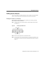
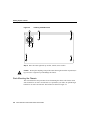
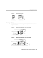
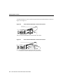
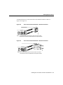
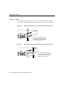
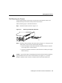
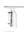
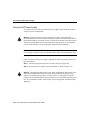
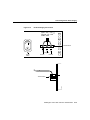
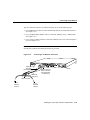
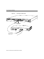
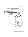
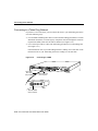
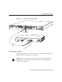
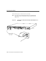
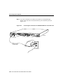
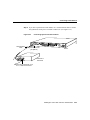
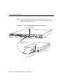
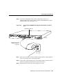
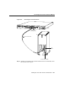
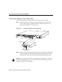
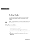
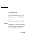
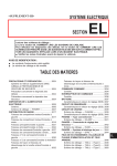
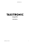
3
CHAPT E R
Installing the Cisco 2524 and
Cisco 2525 Routers
This chapter guides you through the installation of the Cisco 2524 and Cisco 2525 routers
and includes the following sections:
•
•
•
•
•
•
Required Tools and Parts
Setting Up the Chassis
Connecting the DC Power Supply
Connecting to the Network
Connecting the Console Terminal and Modem
What to Do after Installing the Router Hardware
Warning Only trained and qualified personnel should be allowed to install or replace this
equipment. (To see translated versions of this warning, refer to the appendix “Translated
Safety Warnings.”)
Installing the Cisco 2524 and Cisco 2525 Routers 3-1
Required Tools and Parts
Required Tools and Parts
Following are the tools and parts required to install the router:
•
•
•
Flat-blade screwdrivers: small, 3/16-inch (0.476 cm) and medium, 1/4-inch (0.625 cm)
•
Rubber feet for setting the router on a desktop, or rack-mount brackets for mounting the
router in a rack or on a wall (screws not included)
•
An interface cable (not included) for each LAN and WAN interface
ESD-preventive wrist strap
A thread-forming screw (which is not included), to attach a ground wire to the protective
grounding terminal on the rear panel of the chassis
In addition, you might need the following external equipment:
•
Ethernet transceiver, Ethernet 10BaseT hub, or PC with a network interface card for
Ethernet LAN connections.
•
•
Token Ring media attachment unit (MAU) for Token Ring connections.
•
Console terminal (an ASCII terminal or a PC running terminal emulation software)
configured for 9600 baud, 8 data bits, no parity, and 2 stop bits. A terminal is required
unless you are using the AutoInstall procedure. See the section “Connecting the
Console Terminal and Modem” later in this chapter for instructions on connecting a
console terminal.
•
Modem for remote system access (optional).
NT1 device for ISDN BRI WAN connections, if you do not have the module with the
integrated NT1 device.
3-2 Cisco 2524 and Cisco 2525 Router User Guide
Setting Up the Chassis
Setting Up the Chassis
You can set the chassis on a desktop, install it in a rack, or mount it on a wall or other flat
surface. Use the procedure in this section that best fits the needs of your network.
Setting the Chassis on a Desktop
Before setting the router on a desktop, shelf, or other flat, secure surface, perform the
following steps to install the rubber feet:
Step 1 Locate the rubber feet on the black adhesive strip that shipped with the chassis.
(See Figure 3-1.)
Figure 3-1
Identifying the Rubber Feet
H4796
Rubber feet (5)
Black adhesive strip
Step 2 Place the router upside down on a smooth, flat surface.
Step 3 Peel off the rubber feet from the black adhesive strip and place them adhesive-side
down onto the five round, recessed areas on the bottom of the chassis, as shown in
Figure 3-2.
Installing the Cisco 2524 and Cisco 2525 Routers 3-3
Setting Up the Chassis
Figure 3-2
Installing the Rubber Feet
H4795
Fan
Step 4 Place the router right-side up on a flat, smooth, secure surface.
Do not place anything on top of the router that weighs more than 10 pounds (4.5
kg). Excessive weight on top could damage the chassis.
Caution
Rack-Mounting the Chassis
This section describes the procedures for rack-mounting the chassis. The chassis comes
with a bracket for use with a 19-inch rack or, if specified in your order, an optional larger
bracket for use with a 24-inch rack. The brackets are shown in Figure 3-3.
3-4 Cisco 2524 and Cisco 2525 Router User Guide
Setting Up the Chassis
Identifying the Brackets
Bracket for use
with a 19-inch rack
Bracket for use
with a 24-inch rack
H4201
Figure 3-3
Attaching the Brackets
To install the chassis in a rack with the front panel forward, attach the brackets as shown in
Figure 3-4 or Figure 3-5.
19-Inch Bracket Installation—Front Panel Forward
SERIES
H1706
Figure 3-4
Note: The second bracket attaches to the other side of the chassis.
Figure 3-5
24-Inch Bracket Installation—Front Panel Forward
H3893
SERIES
Note: The second bracket attaches to the other side of the chassis.
Installing the Cisco 2524 and Cisco 2525 Routers 3-5
Setting Up the Chassis
To install the chassis in a rack with the rear panel forward, attach the brackets as shown in
Figure 3-6 or Figure 3-7.
Figure 3-6
19-Inch Bracket Installation—Rear Panel Forward
Input: 100-240VAC
Freq: 50.60 Hz
Current: 1.2-0.6A
Watts: 40W
H1704
1
0
Note: The second bracket attaches to the other side of the chassis.
Figure 3-7
24-Inch Bracket Installation—Rear Panel Forward
Input: 100-240VAC
Freq: 50.60 Hz
Current: 1.2-0.6A
Watts: 40W
0
H3894
1
Note: The second bracket attaches to the other side of the chassis.
The brackets can also be installed with the front panel forward.
3-6 Cisco 2524 and Cisco 2525 Router User Guide
Setting Up the Chassis
To install the chassis in a center-mount telco rack, attach the brackets as shown in
Figure 3-8 or Figure 3-9.
Figure 3-8
Telco 19-Inch Bracket Installation—Rear Panel Forward
Input: 100-240VAC
Freq: 50.60 Hz
Current: 1.2-0.6A
Watts: 40W
H1705
1
0
Note: The second bracket attaches to the other side of the chassis.
The brackets can also be installed with the front panel forward.
Figure 3-9
Telco 24-Inch Bracket Installation—Rear Panel Forward
Input: 100-240VAC
Freq: 50.60 Hz
Current: 1.2-0.6A
Watts: 40W
1
H3891
0
Note: The second bracket attaches to the other side of the chassis.
The brackets can also be installed with the front panel forward.
Installing the Cisco 2524 and Cisco 2525 Routers 3-7
Setting Up the Chassis
Installing in a Rack
After the brackets are secured to the chassis, you can rack-mount the chassis. Using the
screws you provide, attach the chassis to the rack as shown in Figure 3-10 or Figure 3-11.
Figure 3-10
Attaching the Chassis to the 19-Inch Rack—Rear Panel Forward
Input: 100-240VAC
Freq: 50.60 Hz
Current: 1.2-0.6A
Watts: 40W
1
H1719
0
Figure 3-11
Note: The second bracket attaches to the
rack at the other side of the chassis.
The brackets can also be installed
with the front panel forward.
Attaching the Chassis to the 24-Inch Rack—Rear Panel Forward
Input: 100-240VAC
Freq: 50.60 Hz
Current: 1.2-0.6A
Watts: 40W
1
Note: The second bracket attaches to the
rack at the other side of the chassis.
The brackets can also be installed
with the front panel forward.
H3892
0
3-8 Cisco 2524 and Cisco 2525 Router User Guide
Setting Up the Chassis
Wall-Mounting the Chassis
Use the smaller brackets (for use with a 19-inch rack) to wall-mount the chassis. The
smaller brackets provide the most stable position for the chassis.
Take the following steps to wall-mount the chassis:
Step 1 Attach the brackets as shown in Figure 3-12.
Figure 3-12
Attaching the Wall-Mount Brackets
Input: 100-240VAC
Freq: 50/60 Hz
Current: 1.2-0.6A
Watts: 40W
H1714
1
0
Step 2 Attach the chassis assembly to the wall as shown in Figure 3-13, using screws and
anchors that you provide. We recommend the following:
•
For the best support of the chassis and cables, attach the brackets so that the
screws align with a vertical wall stud.
•
For the best ventilation of the chassis, mount the chassis with the power supply
and fan at the top.
Caution To prevent the chassis from pulling away from the wall when cables are attached,
align the brackets and screws with a vertical wall stud. (See Figure 3-13.) To ensure
adequate ventilation, make sure there is clearance between the router and the wall.
Installing the Cisco 2524 and Cisco 2525 Routers 3-9
Setting Up the Chassis
Wall-Mounting the Chassis
H5367
SERIAL 0
SERIAL 1
BRI 0
Figure 3-13
3-10 Cisco 2524 and Cisco 2525 Router User Guide
Connecting the DC Power Supply
Connecting the DC Power Supply
The Cisco 2524 router offers an optional direct current (DC) power supply (not available
with the Cisco 2525 router). This section describes the DC power supply specifications and
wiring.
Warning This unit is intended for installation in restricted access areas. (To see translated
versions of the warning, refer to the appendix “Translated Safety Warnings.”)
DC Power Specifications
The DC power supply is intended for use in DC operating environments. Table 3-1 lists the
power supply specifications.
Table 3-1
DC Power Supply Specifications
Description
Design
Specification
Power (input)
40W, –40 to –72 VDC
Wire gauge for power connections
14 AWG1
1. AWG = American Wire Gauge.
Installing the Cisco 2524 and Cisco 2525 Routers 3-11
Connecting the DC Power Supply
Wiring the DC Power Supply
If you ordered a Cisco 2524 router with a DC power supply, follow the directions in this
section to wire the terminal block.
Warning Before performing any of the following procedures, ensure that power is
removed from the DC circuit. To ensure that all power is OFF, locate the circuit breaker on
the panel board that services the DC circuit, switch the circuit breaker to the OFF position,
and tape the switch handle of the circuit breaker in the OFF position. (To see translated
versions of this warning, refer to the appendix “Translated Safety Warnings.”)
Note This product is intended for installation in restricted access areas and is approved for
use with copper conductors only. The installation must comply with all applicable codes.
Figure 3-14 shows the DC power supply terminal block. Take the following steps to wire
the terminal block:
Step 1 Attach the appropriate lugs at the wire end of the power supply cord.
Step 2 Wire the DC power supply to the terminal block, as shown in Figure 3-14.
Warning The illustration shows the DC power supply terminal block. Wire the DC power
supply using the appropriate lugs at the wiring end, as illustrated. The proper wiring
sequence is ground to ground, positive to positive (line to L), and negative to negative
(neutral to N). Note that the ground wire should always be connected first and disconnected
last. (To see translated versions of this warning, refer to the appendix “Translated Safety
Warnings.”)
3-12 Cisco 2524 and Cisco 2525 Router User Guide
Connecting the DC Power Supply
Figure 3-14
DC Power Supply Connections
Input: –40– –72V
Current: 1.5 –1.0A
Watts: 40W
Terminal block
Ground
Negative
Positive
Terminal block
H2679
On/off
switch
Installing the Cisco 2524 and Cisco 2525 Routers 3-13
Connecting to the Network
Warning When stranded wiring is required, use approved wiring terminations, such as
closed-loop or spade-type with upturned lugs. These terminations should be the appropriate
size for the wires and should clamp both the insulation and conductor. (To see translated
versions of this warning, refer to the appendix “Translated Safety Warnings.”)
Caution Do not overtorque the terminal block captive thumbscrew or terminal block
contact screws. The recommended torque is 8.2 0.4 inch-lb.
Warning After wiring the DC power supply, remove the tape from the circuit breaker
switch handle and reinstate power by moving the handle of the circuit breaker to the ON
position. (To see translated versions of this warning, refer to the appendix “Translated
Safety Warnings.”)
Connecting to the Network
This section explains how to connect the router to your network, using the Ethernet (AUI
or 10BaseT) or Token Ring (STP or UTP) ports or the WAN modules.
Warning Do not work on the system or connect or disconnect cables during periods of
lightning activity. (To see translated versions of this warning, refer to the appendix
“Translated Safety Warnings.”)
Connecting to an Ethernet Network
If you have a Cisco 2524 router, it includes both an Ethernet AUI port and a 10BaseT port.
To connect your router to an Ethernet network, you can use either the Ethernet AUI or
10BaseT port, but not both. The first port connected will work. (If you attempt to use both
ports, only the 10BaseT port will work.)
3-14 Cisco 2524 and Cisco 2525 Router User Guide
Connecting to the Network
You can connect the router to your Ethernet network in one of the following ways:
•
Use an Ethernet AUI cable to connect the Ethernet AUI port to an Ethernet transceiver.
(See Figure 3-15.)
•
Use a straight-through 10BaseT cable to connect the 10BaseT port to a 10BaseT hub.
(See Figure 3-16.)
•
Use a crossover 10BaseT cable to connect the 10BaseT port to a PC network interface
card. (See Figure 3-17.)
Note If your Ethernet connection requires jackscrews, remove the slide-latch assembly
from the AUI connector and attach the jackscrews provided.
Connecting to an Ethernet Transceiver
H5368
Figure 3-15
SERIAL 0
SERIAL 1
Ethernet
AUI cable
(not supplied)
Ethernet
transceiver
BRI 0
Ethernet AUI port
DB-15 connector
(with jackscrews
or slide-latch)
Router
BNC connector
To thin
Ethernet
network
To thin
Ethernet
network
Installing the Cisco 2524 and Cisco 2525 Routers 3-15
Connecting to the Network
Connecting to a 10BaseT Hub
H5494
Figure 3-16
SERIAL 0
SERIAL 1
BRI 0
Router
Ethernet 10BaseT
port (RJ-45)
10BaseT hub
AUI
8
7
1
Straight-through
10BaseT cable
3-16 Cisco 2524 and Cisco 2525 Router User Guide
Connecting to the Network
Figure 3-17
BRI 0
Router
Ethernet 10BaseT
port (RJ-45)
PC
OK
ETH
Crossover 10BaseT cable
Network
interface
card
LAN
H5370
SERIAL 1
SER 0
SERIAL 0
Connecting to a PC Network Interface Card
Installing the Cisco 2524 and Cisco 2525 Routers 3-17
Connecting to the Network
Connecting to a Token Ring Network
If you have a Cisco 2524 router, you can connect the router to your Token Ring network in
one of the following ways:
•
Use a shielded Token Ring lobe cable to connect the Token Ring port (DB-9) to a media
attachment unit (MAU). To ensure agency compliance with electromagnetic emissions
requirements (EMI), make sure the cable is shielded. (See Figure 3-18.)
•
Use a twisted-pair cable to connect the Token Ring port (RJ-45) to a Token Ring hub.
(See Figure 3-19.)
If the transmission rate of your Token Ring network is 4 Mbps, use a UTP cable. If the
transmission rate of your Token Ring network is 16 Mbps, use an STP cable.
Connecting to a MAU
SERIAL 0
Token Ring
lobe cable
(not provided)
SERIAL 1
H5371
Figure 3-18
BRI 0
DB-9Token Ring
port connector
MAU
Standard IEEE
802.5 connector
3-18 Cisco 2524 and Cisco 2525 Router User Guide
Router
Connecting to the Network
Connecting to a Token Ring Hub
H5949
Figure 3-19
SERIAL 0
SERIAL 1
BRI 0
Router
Token Ring
port (RJ-45)
Token Ring hub
DB-9
8
7
1
UTP
cable
Connecting to a WAN
Although the illustrations in this section show the Cisco 2524 router, the procedures are the
same for both the Cisco 2524 and Cisco 2525 routers.
Warning Do not work on the system or connect or disconnect cables during periods of
lightning activity. (To see translated versions of this warning, refer to the appendix
“Translated Safety Warnings.”)
Installing the Cisco 2524 and Cisco 2525 Routers 3-19
Connecting to the Network
Take the following steps to connect the router to your WAN:
Step 1 If you have a 2-wire switched 56-kbps module, use a straight-through
RJ-11-to-RJ-11 cable to connect the RJ-11 port to an RJ-11 jack. (See
Figure 3-20.)
Connecting the 2-Wire Switched 56-kbps DSU/CSU Module to an
RJ-11 Jack
H5260
Figure 3-20
2-WIRE
56K
DSU/CSU
TX LB
CD
RX AL
SERIAL 0
SERIAL 1
BRI 0
Router
RJ-11 port
Straight-through
RJ-11 cable
RJ-11 jack
3-20 Cisco 2524 and Cisco 2525 Router User Guide
Connecting to the Network
Step 2 If you have a 4-wire 56/64-kbps DSU/CSU module, use a straight-through
RJ-48S-to-RJ-48S cable to connect the RJ-48S port to an RJ-48S jack. (See
Figure 3-21.)
Connecting the 4-Wire 56/64-kbps DSU/CSU Module to an RJ-48S
Jack
H5261
Figure 3-21
4-WIRE
56K/64K
DSU/CSU
TX LB
CD
RX AL
SERIAL 0
SERIAL 1
BRI 0
Router
RJ-48S port
Straight-through
RJ-48S cable
RJ-48S jack
Installing the Cisco 2524 and Cisco 2525 Routers 3-21
Connecting to the Network
Step 3 If you have a fractional T1/T1 DSU/CSU module, use a straight-through
RJ-48C-to-RJ-48C cable to connect the RJ-48C port to an RJ-48C jack. (See
Figure 3-22.)
Connecting the Fractional T1/T1 DSU/CSU Module to an RJ-48C Jack
H5262
Figure 3-22
MON JACK
TX LB
FTI/TI
DSU/CSU
CD
RX AL
SERIAL 0
SERIAL 1
Router
BRI 0
RJ-48C port
Straight-through
RJ-48C cable
RJ-48C jack
3-22 Cisco 2524 and Cisco 2525 Router User Guide
Connecting to the Network
Step 4 If you have a synchronous serial module, use a serial transition cable to connect
the synchronous serial port to a modem or DSU/CSU. (See Figure 3-23.)
Connecting Synchronous Serial Cables
H5369
Figure 3-23
SERIAL
ACTIVITY
SERIAL 0
Serial transition
cable
SERIAL 1
Synchronous serial
port (DB-60)
BRI 0
Router
DSU/CSU or
other DCE
EIA/TIA-232, EIA/TIA-449, V.35,
X.21, or EIA-530 connector
Installing the Cisco 2524 and Cisco 2525 Routers 3-23
Connecting to the Network
Step 5 If you have an ISDN BRI module (without an integrated NT1 device), use a
straight-through RJ-45-to-RJ-45 cable to connect the ISDN BRI (RJ-45) port to
an NT1 device. (See Figure 3-24.)
Figure 3-24
Connecting the ISDN BRI Module to an NT1 Device
ISDN BRI port (RJ-45)
ISDN-BRI
SERIAL 0
ACTIVITY
SERIAL 1
BRI 0
Router
H5257
Straight-through
RJ-45-to-RJ-45 cable
S/T interface
NT1 device
3-24 Cisco 2524 and Cisco 2525 Router User Guide
Connecting to the Network
Step 6 If you have an ISDN BRI module with an integrated NT1 device, use a
straight-through RJ-45-to-RJ-45 cable to connect the ISDN BRI (RJ-45) port to
an RJ-45 or RJ-11 jack. (See Figure 3-25.)
Figure 3-25
Connecting the ISDN BRI with Integrated NT1 Module to an RJ-45
Jack
H5258
ISDN BRI port (RJ-45)
ISDN-BRI
with NTI
SERIAL 0
SERIAL 1
ACT NT1
U
BRI 0
Router
Straight-through cable
with RJ-45 or RJ-11
connectors
RJ-45 or
RJ-11 jack
Step 7 If the router is configured with fewer than three WAN modules, install a blank slot
cover over each open slot to ensure proper airflow.
Step 8 Using an M 3.5 thread-forming screw (not included), attach a ground wire to the
protective grounding terminal on the rear panel of the chassis.
Step 9 Connect the power cable to the router and the power source.
Installing the Cisco 2524 and Cisco 2525 Routers 3-25
Connecting the Console Terminal and Modem
Connecting the Console Terminal and Modem
You use the console terminal for local administrative access to the router. You can connect
only a terminal to the console port. You can use the auxiliary port with a terminal or a
modem for remote access to the router.
Connecting to the Console Port
Take the following steps to connect a terminal (an ASCII terminal or a PC running terminal
emulation software) to the console port on the router:
Step 1 Connect the terminal using an RJ-45 roll-over cable and an RJ-45-to-DB-25 or
RJ-45-to-DB-9 adapter. The adapters provided by Cisco Systems are labeled
Terminal. Other types of adapters are not included. (See Figure 3-26.)
Additional information on roll-over cable pinouts is provided in the appendix
“Cabling Specifications for the Cisco 2524 and Cisco 2525 Routers.”
3-26 Cisco 2524 and Cisco 2525 Router User Guide
Connecting the Console Terminal and Modem
Figure 3-26
SERIAL 0
Connecting the Console Terminal
SERIAL 1
BRI 0
Router
Console port
connector (RJ-45)
PC
OK
I/O
card
H5366
AUX
SER 0
LAN
ETH
RJ-45 roll-over cable
RJ-45-to-DB-25 adapter
Step 2 Configure your terminal or PC terminal emulation software for 9600 baud, 8 data
bits, no parity, and 2 stop bits.
Installing the Cisco 2524 and Cisco 2525 Routers 3-27
Connecting the Console Terminal and Modem
Connecting a Modem to the Auxiliary Port
Take the following steps to connect a modem to the auxiliary port on the router:
Step 1 Connect a modem to the auxiliary port using an RJ-45 roll-over cable with an
RJ-45-to-DB-25 or RJ-45-to-DB-9 adapter. The adapter provided by Cisco
Systems is labeled Modem. (See Figure 3-27.)
Connecting a Modem to the Auxiliary Port
H5270
Figure 3-27
SERIAL 0
SERIAL 1
BRI 0
Router
Auxiliary port
connector (RJ-45)
RJ-45 roll-over
cable
Modem
RJ-45-to-DB-25 adapter
(EIA/TIA-232)
Step 2 Make sure that your modem and the auxiliary port on the router are configured for
the same transmission speed (38400 baud is typical) and hardware flow control
with Data Carrier Detect (DCD) and Data Terminal Ready (DTR) operations.
Warning This equipment is intended to be grounded. Ensure that the host is connected to
earth ground during normal use. (To see translated versions of this warning, refer to the
appendix “Translated Safety Warnings.”)
3-28 Cisco 2524 and Cisco 2525 Router User Guide
What to Do after Installing the Router Hardware
What to Do after Installing the Router Hardware
After you have installed the router, proceed to the chapter “Configuring the Cisco 2524 and
Cisco 2525 Routers” for software configuration information.
Installing the Cisco 2524 and Cisco 2525 Routers 3-29
What to Do after Installing the Router Hardware
3-30 Cisco 2524 and Cisco 2525 Router User Guide