1
Agilent N9360A
Multi UE Tester
GSM User Manual
Agilent Technologies
Notices
© Agilent Technologies, Inc. 2006
Manual Part Number
No part of this manual may be reproduced in any form or by any means
(including electronic storage and
retrieval or translation into a foreign
language) without prior agreement
and written consent from Agilent
Technologies, Inc. as governed by
United States and international copyright laws.
N9360-90700
Edition
First Edition, May 2006
Printed in Malaysia
Agilent Technologies Microwave
Products (Malaysia) Sdn. Bhd.
Bayan Lepas Free Industrial Zone
11900 Penang, Malaysia
Warranty
The material contained in this document is provided “as is,” and is subject to being changed, without notice,
in future editions. Further, to the
maximum extent permitted by applicable law, Agilent disclaims all warranties, either express or implied,
with regard to this manual and any
information contained herein, including but not limited to the implied
warranties of merchantability and fitness for a particular purpose. Agilent
shall not be liable for errors or for
incidental or consequential damages
in connection with the furnishing,
use, or performance of this document
or of any information contained
herein. Should Agilent and the user
have a separate written agreement
with warranty terms covering the
material in this document that conflict with these terms, the warranty
terms in the separate agreement
shall control.
Technology Licenses
The hardware and/or software described
in this document are furnished under a
license and may be used or copied only in
accordance with the terms of such license.
Restricted Rights Legend
If software is for use in the performance of
a U.S. Government prime contract or subcontract, Software is delivered and
licensed as “Commercial computer software” as defined in DFAR 252.227-7014
defined in FAR 2.101(a) or as “Restricted
computer software” as defined in FAR
52.227-19 (June 1987) or any equivalent
agency regulation or contract clause. Use,
duplication or disclosure of Software is
subject to Agilent Technologies’ standard
commercial license terms, and non-DOD
Departments and Agencies of the U.S.
Government will receive no greater than
Restricted Rights as defined in FAR
52.227-19(c)(1-2) (June 1987). U.S. Government users will receive no greater than
Limited Rights as defined in FAR 52.227-14
(June 1987) or DFAR 252.227-7015 (b)(2)
(November 1995), as applicable in any
technical data.
Safety Notices
CAUTION
A CAUTION notice denotes a hazard. It calls attention to an operating procedure, practice, or the like
that, if not correctly performed or
adhered to, could result in damage
to the product or loss of important
data. Do not proceed beyond a
CAUTION notice until the indicated
conditions are fully understood and
met.
WARNING
A WARNING notice denotes a
hazard. It calls attention to an
operating procedure, practice, or
the like that, if not correctly performed or adhered to, could result
in personal injury or death. Do not
proceed beyond a WARNING
notice until the indicated conditions are fully understood and
met.
1
Preface
Thank-you for purchasing the Agilent N9360A. GSM (Global System for
Mobile Communication). This is the GSM software for the N9360A Multi
UE Tester.
• Before using the tester, the user is advised to read this manual
carefully to ensure correct usage and also to fully utilize the tester
capability.
• This manual is a reference document and the user is advised to keep it
carefully for future reference.
• The manual includes the characteristics of GSM, the tester operation,
test procedures and screen references.
• Refer to the N9360A Multi UE Tester Installation Guide for information
regarding installation and details of the tester. Refer also to the
N9360A W-CDMA User Manual for information about the test
functions of W-CDMA (Wideband Code Division Multiple Access).
Notation
The following notations are used in this manual:
• Softkey
: indicates a softkey;
• [Screen Name]
: indicates a screen name;
• Tester/tester
: indicates the N9360A Multi UE Tester.
Notices
• The information contained in this manual is subjected to change with
notice.
• No part of this manual may be reproduced either mechanically,
electronically or otherwise, without permission from Agilent
Technologies, Inc.
Trademarks
• Ethernet is the registered trademark of the Xerox Corporation.
• EPSON is the registered trademark of the EPSON Corporation.
• Other product names and companies used herein are trademarks or
registered trademarks of their respective companies or Agilent
Technologies, Inc. For registered trademarks, the trademarks symbols
® and ™ are omitted in this manual.
N9360A Multi UE Tester GSM User Manual
1-3
1
THIS PAGE IS INTENTIONALLY LEFT BLANK
1-4
N9360A Multi UE Tester GSM User Manual
Contents
Preface 1-3
Notation
1-3
Notices 1-3
Trademarks 1-3
1
Legal Information
Legal Information
1-2
Warranty
1-2
Technology Licenses
1-2
Restricted Rights Legend
1-2
Service And Support
1-3
Agilent On The Web 1-3
Agilent By Phone 1-3
2
Caution and Safety Requirements
Safety Information
2-2
Safety Summary 2-2
Safety Notices
2-2
Warning Label
2-2
General
2-3
When Operating The Tester
3
Overview
Functions
3-2
Features 3-4
Standard Configuration
Accessories
3-6
4
3-5
Operating Procedures
Test Flow 4-2
Preparation for Each Test
Connection
4-4
Test Procedure
4-5
Ending a Test 4-87
5
2-3
4-3
Screen Reference
Screen Flow Chart 5-2
Top Menu Screen
5-3
Firmware Update Screen 5-10
Initial Screen
5-12
Return to Menu Screen 5-15
N9360A Multi UE Tester GSM User Manual
5
Automatic Test 5-16
Manual Test (GSM Mode) 5-45
Manual Test (GPRS Mode)
5-78
Manual Test (EGPRS Mode)
5-104
TX Analyzer
5-137
Signal Generator
5-166
Configuration
5-168
Configuration: Test Condition Screen
6
5-176
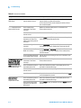
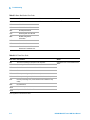
Troubleshooting
Item to be checked 6-2
Error Information 6-6
7
Performance and Specifications
Measurement Performance
8
Appendix A Input Fields and Allowable Choices or Ranges
9
Appendix B General Information in the GSM System
The GSM System
10
9-2
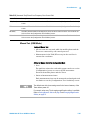
Appendix C CAU-17 Antenna Coupler
Introduction
10-2
Specifications 10-2
Operating the Antenna Coupler
6
7-2
10-3
N9360A Multi UE Tester GSM User Manual
List Of Figures
4
Operating Procedures
Figure 4-1. Test Flow 4-2
Figure 4-2. Typical Test Setup of the Tester
4-3
Figure 4-3. Connecting a Printer 4-5
Figure 4-4. Display Annotation 4-6
Figure 4-5. Value Storage Softkeys
4-9
Figure 4-6. Memory Function 4-10
Figure 4-7. Value Storage Softkeys
4-12
Figure 4-8. Changing Magnification Softkey 4-13
Figure 4-9. [Top Menu] Screen 4-14
Figure 4-10. [Initial] Screen 4-15
Figure 4-11. [Initial] Screen 4-16
Figure 4-12. [Configuration] Screen 4-20
Figure 4-13. [Configuration: Test Sequence] Screen 4-22
Figure 4-14. [Initial] Screen 4-23
Figure 4-15. [Configuration] Screen 4-24
Figure 4-16. [Configuration: Test Sequence] Screen 4-25
Figure 4-17. [Configuration: Test Condition] Screen 4-26
Figure 4-18. [Automatic Test: Stand-by] Screen 4-27
Figure 4-19. [Automatic Test: Stand-by] Value Screen 4-28
Figure 4-20. [Stand-by] Summary Screen 4-30
Figure 4-21. [Stand-by] Graph/Value Screen 4-31
Figure 4-22. [Initial] Screen 4-32
Figure 4-23. [Configuration] Screen 4-33
Figure 4-24. [Configuration: Test Condition] Screen 4-34
Figure 4-25. [Manual Test: Stand-by] Screen (GSM Mode) 4-35
Figure 4-26. [Measuring] MS Call Screen (GSM Mode) 4-36
Figure 4-27. [Measuring] Summary Screen (GSM Mode) 4-37
Figure 4-28. [Measuring] Graph/ Value Screen (GSM Mode) 4-38
Figure 4-29. [Measuring] Graph/Value Zoomed Screen (GSM
Mode)
4-39
Figure 4-30. [Measuring] Spectrum Monitor Screen (GSM Mode) 4-40
Figure 4-31. [Stand-by] After Release Screen (GSM Mode) 4-41
Figure 4-32. [Initial] Screen 4-42
Figure 4-33. [Configuration] Screen 4-43
Figure 4-34. [Configuration: Test Condition] Screen 4-44
Figure 4-35. [Manual Test: Stand-by] Screen (GSM Mode) 4-45
Figure 4-36. [Measuring] BS Call Screen (GSM Mode) 4-46
Figure 4-37. [Measuring] Summary Screen (GSM Mode) 4-47
Figure 4-38. [Stand-by] After Release Screen (GSM Mode) 4-48
Figure 4-39. [Initial] Screen 4-49
N9360A Multi UE Tester GSM User Manual
7
Figure 4-40. [Configuration] Screen 4-50
Figure 4-41. [Configuration: Test Condition] Screen 4-51
Figure 4-42. [Manual Test: Stand-by] Screen (GSM Mode) 4-52
Figure 4-43. [Measuring] MS Call Emergency Call Screen (GSM
Mode)
4-53
Figure 4-44. [Measuring] Emergency Call Summary Screen (GSM
Mode)
4-54
Figure 4-45. [Stand-by] After Release Screen (GSM Mode) 4-55
Figure 4-46. [Initial] Screen 4-56
Figure 4-47. [Configuration] Screen 4-57
Figure 4-48. [Configuration: Test Condition] Screen 4-58
Figure 4-49. [Manual Test: Stand-by] GPRS Mode Screen 4-59
Figure 4-50. [Measuring] Attached Screen (GPRS Mode) 4-60
Figure 4-51. [Measuring] Connected Screen (GPRS Mode) 4-61
Figure 4-52. [Measuring] Summary Screen (GPRS Mode) 4-62
Figure 4-53. [Measuring] Graph/Value Screen (GPRS Mode)
4-63
Figure 4-54. [Measuring] Graph/Value Zoomed Screen (GPRS
Mode)
4-64
Figure 4-55. [Measuring] Spectrum Monitor Screen (GPRS
Mode)
4-65
Figure 4-56. [Initial] Screen 4-66
Figure 4-57. [Configuration] Screen 4-67
Figure 4-58. [Configuration: Test Condition] Screen 4-68
Figure 4-59. [Manual Test: Stand-by] EGPRS Mode Screen 4-69
Figure 4-60. [Measuring] Attached Screen (EGPRS Mode) 4-70
Figure 4-61. [Measuring] Connected Screen (EGPRS Mode) 4-71
Figure 4-62. [Measuring] Summary Screen (EGPRS Mode) 4-72
Figure 4-63. [Measuring] Graph/Value Screen (EGPRS Mode) 4-73
Figure 4-64. [Measuring] Graph/Value Zoomed Screen (EGPRS
Mode)
4-74
Figure 4-65. [Measuring] Spectrum Monitor Screen (EGPRS
Mode)
4-75
Figure 4-66. [Initial] Screen 4-76
Figure 4-67. [Configuration] Screen 4-77
Figure 4-68. [Configuration: Test Condition] Screen 4-78
Figure 4-69. [TX Analyzer: Stand-by] Screen 4-79
Figure 4-70. [Stand-by] Summary Screen 4-80
Figure 4-71. [Stand-by] Graph/Value Screen 4-81
Figure 4-72. [Stand-by] Graph/Value Zoom Screen 4-82
Figure 4-73. [Stand-by] Spectrum Monitor Screen
4-83
Figure 4-74. [Initial] Screen 4-84
Figure 4-75. [Configuration] Screen 4-85
Figure 4-76. [Signal Generator] Screen
4-86
8
N9360A Multi UE Tester GSM User Manual
5
Screen Reference
Figure 5-1. Screen Flow Chart 5-2
Figure 5-2. Selectable Systems
5-3
Figure 5-3. [Top Menu] Screen 5-4
Figure 5-4. [Configuration] Screen 5-6
Figure 5-5. Part of [Configuration] screen (without Option E00) 5-7
Figure 5-6. Part of [Configuration] screen (without Option E01) 5-7
Figure 5-7. [Firmware Update] Screen 5-11
Figure 5-8. [Initial] Screen 5-13
Figure 5-9. [Return to Menu] Screen 5-15
Figure 5-10. [Automatic Test: Stand-by] Simplified Screen 5-17
Figure 5-11. [Automatic Test: Stand-by] Detailed Screen
5-17
Figure 5-12. [Automatic Test: Stand-by] Value Screen 5-18
Figure 5-13. [Measuring] Simplified Screen 5-23
Figure 5-14. [Measuring] Detailed Screen 5-23
Figure 5-15. [Measuring] Value Screen 5-24
Figure 5-16. [Measuring] Talk Simplified Screen 5-26
Figure 5-17. [Measuring] Talk Detailed Screen 5-26
Figure 5-18. [Measuring] Talk Value Screen 5-27
Figure 5-19. [Stand-by] Aborted Simplified Screen
5-29
Figure 5-20. [Measuring] Next Sequence 2 Screen
5-31
Figure 5-21. [Stand-by] Summary Simplified Screen 5-33
Figure 5-22. [Stand-by] Summary Detailed Screen 5-33
Figure 5-23. [Stand-by] Summary Value Screen
5-34
Figure 5-24. [Stand-by] Peak TX Power Screen 5-37
Figure 5-25. [Stand-by] Burst Timing/ Power Ramp Screen 5-39
Figure 5-26. [Stand-by] Burst Timing/ Power Ramp Zoomed
Screen
5-40
Figure 5-27. [Stand-by] Phase Error Screen
5-42
Figure 5-28. [Stand-by] Sensitivity/ RX Quality/ RX Level Screen
5-44
Figure 5-29. [Manual Test: Stand-by] GSM Mode Screen
5-46
Figure 5-30. [Manual Test: Measuring] MS Call Screen 5-51
Figure 5-31. [Measuring] BS Call Connection Screen 5-52
Figure 5-32. [Measuring] MS Call Connection Screen
5-52
Figure 5-33. [Measuring] BS Call Screen 5-56
Figure 5-34. [Measuring] MS Call Screen 5-57
Figure 5-35. [Stand-by] BS Call Summary Screen 5-58
Figure 5-36. [Stand-by] MS Call Summary Screen 5-59
Figure 5-37. [Measuring] Peak TX Power/Burst Timing/Power Ramp
Screen
5-61
Figure 5-38. [Measuring] Peak TX Power/ Burst Timing/ Power Ramp
Zoomed Screen 5-62
Figure 5-39. [Measuring] Phase Error/ Frequency Error Screen 5-65
N9360A Multi UE Tester GSM User Manual
9
Figure 5-40. [Measuring] Sensitivity/ RX Quality/ RX Level
Screen
5-68
Figure 5-41. [Measuring] Spectrum Monitor Screen 5-72
Figure 5-42. [Stand-by] SMS Screen 5-75
Figure 5-43. [Manual Test: Stand-by] GPRS Mode Screen 5-80
Figure 5-44. [Measuring] Attached Screen 5-84
Figure 5-45. [Measuring] Connected Screen 5-87
Figure 5-46. [Stand-by] Summary Screen 5-88
Figure 5-47. [Measuring] Peak TX Power/ Burst Timing/ Power Ramp
Screen
5-91
Figure 5-48. [Measuring] Peak TX Power/ Burst Timing/ Power Ramp
Zoomed Screen 5-91
Figure 5-49. [Measuring] Phase Error/ Frequency Error Screen 5-95
Figure 5-50. [Measuring] Sensitivity in BLER Screen 5-98
Figure 5-51. [Measuring] Spectrum Monitor Screen 5-101
Figure 5-52. [Manual Test: Stand-by] EGPRS Mode Screen 5-106
Figure 5-53. [Measuring] Attached Screen 5-110
Figure 5-54. [Measuring] Connected Screen 5-113
Figure 5-55. [Stand-by] Summary Screen 5-115
Figure 5-56. [Measuring] Peak TX Power/ Burst Timing/ Power Ramp
Screen
5-117
Figure 5-57. [Measuring] Peak TX Power/ Burst Timing/ Power Ramp
Zoomed Screen 5-118
Figure 5-58. [Measuring] Phase Error/ Frequency Error Screen 5-121
Figure 5-59. [Measuring] EVM Screen 5-125
Figure 5-60. [Measuring] Sensitivity in BLER Screen 5-128
Figure 5-61. [Output RF Spectrum] Screen 5-131
Figure 5-62. [Measuring] Spectrum Monitor Screen 5-134
Figure 5-63. [TX Analyzer: Stand-by] Screen 5-138
Figure 5-64. [Measuring] Screen
5-142
Figure 5-65. [Stand-by] Summary Screen 5-143
Figure 5-66. [Stand-by] Peak TX Power/ Burst Timing/ Power Ramp
Screen
5-145
Figure 5-67. [Stand-by] Peak TX Power/ Burst Timing/ Power Ramp
Zoomed Screen 5-146
Figure 5-68. [Stand-by] Phase Error/ Frequency Error Screen 5-150
Figure 5-69. [Stand-by] EVM Frequency Error/OOS Screen
5-154
Figure 5-70. [Output RF Spectrum] Screen 5-158
Figure 5-71. [Stand-by] Spectrum Monitor Span 0 - 400kHz
Screen
5-161
Figure 5-72. [Stand-by] Spectrum Monitor Span +-100kHz
Screen
5-163
Figure 5-73. [Signal Generator] Screen
5-167
Figure 5-74. [Configuration] Screen 5-169
Figure 5-75. [Configuration: Test Sequence] Screen 5-173
10
N9360A Multi UE Tester GSM User Manual
Figure 5-76. [Configuration: Test Condition] (GSM Mode)
Screen
5-177
Figure 5-77. [Configuration: Test Condition] (GPRS Mode)
Screen
5-178
Figure 5-78. [Configuration: File Management] Screen
5-183
Figure 5-79. [Configuration: File Management] Save-1 Screen
Figure 5-80. [Configuration: File Management] Save-2 Screen
Figure 5-81. [Configuration: File Management] Save-3 Screen
Figure 5-82. [Configuration: File Management] Save-4 Screen
Figure 5-83. [Configuration: File management] Save-5 Screen
Figure 5-84. [Configuration: File Management] Recall-1 Screen
Figure 5-85. [Configuration: File Management] Recall-2 Screen
Figure 5-86. [Configuration: File Management] Recall-3 Screen
Figure 5-87. [Configuration: File Management] Delete-1 Screen
Figure 5-88. [Configuration: File Management] Delete-2 Screen
Figure 5-89. [Configuration: File Management] Delete-3 Screen
Figure 5-90. [Configuration: File Management] Replace-1
Screen
5-197
Figure 5-91. [Configuration: File Management] Replace-2
Screen
5-198
Figure 5-92. [Configuration: File Management] Replace-3
Screen
5-199
6
5-185
5-186
5-187
5-188
5-189
5-191
5-192
5-193
5-194
5-195
5-196
Troubleshooting
Figure 6-1. An Example of [Error] Screens
N9360A Multi UE Tester GSM User Manual
6-7
11
THIS PAGE IS INTENTIONALLY LEFT BLANK.
12
N9360A Multi UE Tester GSM User Manual
List Of Tables
1
Legal Information
Table 1-1. Agilent Call Centers and Regional Headquarters
3
1-3
Overview
Table 3-1. Main Functions
3-2
Table 3-2. Configuration
3-5
Table 3-3. Accessories
3-6
4
Operating Procedures
Table 4-1. Description of the Display Annotation
5
4-6
Screen Reference
Table 5-1. [Configuration] Screen Input Field
5-7
Table 5-2. [Initial] Screen Input Field
5-14
Table 5-3. [Automatic Test: Stand-by] Screen Input Field
5-19
Table 5-4. Automatic Test Measurement Item
5-20
Table 5-5. [Automatic Test: Stand-by] Screen Mobile Phone
Information 5-21
Table 5-6. [Automatic Test: Measuring] Screen Mobile Phone
Information 5-25
Table 5-7. [Automatic Test: Stand-by] Summary Screen Input
Field
5-35
Table 5-8. [Automatic Test: Measuring] Screen Mobile Phone
Information 5-36
Table 5-9. [Automatic Test] Peak TX Power Screen Field 5-38
Table 5-10. [Automatic Test] Burst Timing/Power Ramp Screen
Field
5-41
Table 5-11. [Automatic Test] Phase Error/Frequency Error Screen
Field
5-43
Table 5-12. [Automatic Test] Phase Error/Frequency Error Screen
Field
5-44
Table 5-13. [Manual Test: Stand-by] Screen GSM Mode Input
Field
5-47
Table 5-14. Manual Test GSM Mode Measurement Item 5-49
Table 5-15. [Manual Test: Stand-by] GSM Mode Screen Mobile Phone
Information 5-49
Table 5-16. [Manual Test: Stand-by] Screen GSM Mode Input
Field
5-53
Table 5-17. [Manual Test: Measuring] GSM Mode Connection Screen
Mobile Phone Information
5-54
Table 5-18. [Manual Test: Stand-by] Screen GSM Mode Input
Field
5-63
N9360A Multi UE Tester GSM User Manual
13
Table 5-19. [Manual Test] GSM Mode Peak TX Power/Burst
Timing/Power Ramp Screen Field
5-64
Table 5-20. [Manual Test] GSM Mode Phase Error/Frequency Error Input
Field
5-67
Table 5-21. [Manual Test] GSM Mode Phase Error/Frequency Error
Screen Field
5-68
Table 5-22. [Manual Test] GSM Mode Sensitivity/ RX Quality/ RX Level
Screen Input Field
5-69
Table 5-23. [Manual Test] GSM Mode Sensitivity/RX Quality/RX Level
Screen Field
5-71
Table 5-24. [Manual Test] GSM Mode Spectrum Monitor Screen Input
Field
5-73
Table 5-25. [Manual Test] GSM Mode Sensitivity/RX Quality/RX Level
Screen Field
5-74
Table 5-26. [Manual Test] GSM Mode SMS Screen Input Field
5-76
Table 5-27. [Manual Test] GSM Mode SMS Information
5-77
Table 5-28. Slot Configuration and Measurement Slot
5-79
Table 5-29. [Manual Test: Stand-by] GPRS Mode Screen Input
Field
5-81
Table 5-30. Manual Test GPRS Mode Measurement Item 5-82
Table 5-31. Manual Test GPRS Mode Measurement Item 5-83
Table 5-32. [Manual Test: Measuring] GPRS Mode Screen Input
Field
5-85
Table 5-33. [Manual Test] GPRS Mode Attached Screen Mobile Phone
Information 5-86
Table 5-34. [Manual Test] GPRS Mode Peak TX Power/ Burst
Timing/Power Ramp Screen Input Field 5-93
Table 5-35. [Manual Test] GPRS Mode Peak TX Power/Burst
Timing/Power Ramp Screen Field
5-94
Table 5-36. [Manual Test] GPRS Mode Phase Error/Frequency Error
Screen Input Field
5-96
Table 5-37. [Manual Test] GPRS Mode Phase Error/Frequency Error
Screen Field
5-97
Table 5-38. [Manual Test] GPRS Mode Sensitivity Screen Input
Field
5-99
Table 5-39. [Manual Test] GPRS Mode Sensitivity Screen Field
5-100
Table 5-40. [Manual Test] GPRS Mode Spectrum Monitor Screen Input
Field
5-102
Table 5-41. [Manual Test] GPRS Mode Spectrum Monitor Screen
Field
5-103
Table 5-42. Slot Configuration and Measurement Slot
5-104
Table 5-43. [Manual Test: Stand-by] EGPRS Mode Screen Input
Field
5-107
Table 5-44. Manual Test EGPRS Mode Measurement Item 5-108
Table 5-45. Manual Test EGPRS Mode Measurement Item 5-109
14
N9360A Multi UE Tester GSM User Manual
Table 5-46. [Manual Test: Measuring] EGPRS Mode Screen Input
Field
5-111
Table 5-47. [Manual Test] EGPRS Mode Attached Screen Mobile Phone
Information 5-112
Table 5-48. [Manual Test] EGPRS Mode Peak TX Power/ Burst
Timing/Power Ramp Screen Input Field 5-119
Table 5-49. [Manual Test] EGPRS Mode Peak TX Power/Burst
Timing/Power Ramp Screen Field
5-120
Table 5-50. [Manual Test] EGPRS Mode Phase Error/Frequency Error
Screen Input Field
5-123
Table 5-51. [Manual Test] EGPRS Mode Phase Error/Frequency Error
Screen Field
5-124
Table 5-52. [Manual Test] EGPRS Mode EVM Screen Input Field
5-126
Table 5-53. [Manual Test] EGPRS Mode EVM Screen Field 5-127
Table 5-54. [Manual Test] EGPRS Mode Sensitivity Screen Input
Field
5-129
Table 5-55. [Manual Test] EGPRS Mode Sensitivity Screen Field
5-130
Table 5-56. [Manual Test] EGPRS Mode ORFS Screen Input
Field
5-132
Table 5-57. [Manual Test] EGPRS Mode ORFS Screen Field
5-133
Table 5-58. [Manual Test] EGPRS Mode Spectrum Monitor Screen Input
Field
5-135
Table 5-59. [Manual Test] EGPRS Mode Spectrum Monitor Screen
Field
5-136
Table 5-60. [TX Analyzer: Stand-by] Screen Input Field
5-139
Table 5-61. TX Analyzer Measurement Item 5-141
Table 5-62. [TX Analyzer] Peak TX Power/ Burst Timing/ Power Ramp
Screen Input Field
5-147
Table 5-63. [TX Analyzer] Peak TX Power/Burst Timing/Power Ramp
Screen Field
5-149
Table 5-64. [TX Analyzer] Phase Error/Frequency Error Screen Input
Field
5-151
Table 5-65. [TX Analyzer] Phase Error/Frequency Error Screen
Field
5-153
Table 5-66. [TX Analyzer] EVM/Frequency Error/OOS Screen Input
Field
5-155
Table 5-67. [TX Analyzer] EVM/Frequency Error/OOS Screen
Field
5-157
Table 5-68. [TX Analyzer] EGPRS Mode ORFS Screen Input Field
5-159
Table 5-69. [Manual Test] EGPRS Mode ORFS Screen Field
5-160
Table 5-70. [TX Analyzer] Spectrum Monitor (span 0 - 400kHz) Screen
Field
5-162
Table 5-71. [TX Analyzer] Spectrum Monitor (span +-100kHz) Screen
Field
5-164
Table 5-72. [TX Analyzer] Spectrum Monitor Screen Input Field
5-165
Table 5-73. [Signal Generator] Screen Input Field 5-168
N9360A Multi UE Tester GSM User Manual
15
Table 5-74. [Configuration] Screen Input Field
5-170
Table 5-75. Setting Combination for Automatic Test Flow
5-174
Table 5-76. [Configuration: Test Sequence] Screen Input Field
5-174
Table 5-77. Configuration: Test Sequence Measurement Item 5-176
Table 5-78. [Configuration: Test Sequence] Screen Input Field
5-179
Table 5-79. Configuration: Test Condition Measurement Item 5-182
6
Troubleshooting
Table 6-1. Item to be checked 6-2
Table 6-2. The time for measuring 6-6
Table 6-3. Alarm Notification Error Code
Table 6-4. UI Timer Error Code
6-8
7
6-7
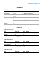
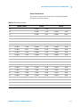
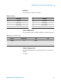
Performance and Specifications
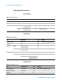
Table 7-1. Peak TX Power 7-2
Table 7-2. Power Ramp
7-2
Table 7-3. Frequency Error 7-2
Table 7-4. Phase Error
7-3
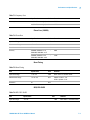
Table 7-5. Burst Timing
7-3
Table 7-6. BER, FER / BLER 7-3
Table 7-7. RX Quality 7-4
Table 7-8. RX Level
7-4
Table 7-9. Actual Timing Advance 7-4
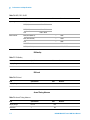
Table 7-10. Spectrum Monitor
7-5
Table 7-11. Frequency Offset 7-5
Table 7-12. AM Modulation
7-5
Table 7-13. EVM (8-PSK)
7-5
Table 7-14. Origin Offset suppression
7-6
Table 7-15. Output RF Spectrum 7-6
8
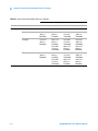
Appendix A Input Fields and Allowable Choices or Ranges
Table 8-1. Input Fields and Allowable Choices or Ranges
9
8-2
Appendix B General Information in the GSM System
Table 9-1. RF Channels 9-2
Table 9-2. Power Classes
9-2
Table 9-3. Power Control Levels
9-3
Table 9-4. RX Level
9-4
Table 9-5. RX Quality 9-5
Table 9-6. Limits for BER and FER
9-5
16
N9360A Multi UE Tester GSM User Manual
1
Legal Information
Warranty 1-2
Technology Licenses 1-2
Restricted Rights Legend 1-2
Service And Support 1-3
Agilent On The Web 1-3
Agilent By Phone 1-3
Agilent Technologies
1-1
1
Legal Information
Legal Information
Warranty
The material contained in this document is provided “as is,” and
is subject to being changed, without notice, in future editions.
Further, to the maximum extent permitted by applicable law,
Agilent disclaims all warranties, either express or implied, with
regard to this manual and any information contained herein,
including but not limited to the implied warranties of
merchantability and fitness for a particular purpose. Agilent
shall not be liable for errors or for incidental or consequential
damages in connection with the furnishing, use, or performance
of this document or of any information contained herein.
Should Agilent and the user have a separate written agreement
with warranty terms covering the material in this document
that conflict with these terms, the warranty terms in the
separate agreement shall control.
Technology Licenses
The hardware and/or software described in this document are
furnished under a license and may be used or copied only in
accordance with the terms of such license.
Restricted Rights Legend
If software is for use in the performance of a U.S. Government
prime contract or subcontract, Software is delivered and
licensed as “Commercial computer software” as defined in
DFAR 252.227-7014 (June 1995), or as a “commercial item” as
defined in FAR 2.101(a) or as “Restricted computer software” as
defined in FAR 52.227-19 (June 1987) or any equivalent agency
regulation or contract clause. Use, duplication or disclosure of
Software is subject to Agilent Technologies’ standard
commercial license terms, and non-DOD Departments and
Agencies of the U.S. Government will receive no greater than
Restricted Rights as defined in FAR 52.227-19(c)(1-2)(June
1987). U.S. Government users will receive no greater than
Limited Rights as defined in FAR 52.227-14 (June 1987) or
DFAR 252.227-7015 (b)(2)(November 1995), as applicable in any
technical data.
1-2
N9360A Multi UE Tester GSM User Manual
Legal Information
1
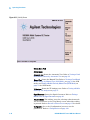
Service And Support
Any adjustment, maintenance, or repair of this product must be
performed by qualified personnel. Contact your customer
engineer through your local Agilent Technologies Service
Center.
Agilent On The Web
You can find information about technical and professional
services, product support, and equipment repair and service on
the Web: http://www.agilent.com/
Double-click the link to Test & Measurement. Select your country
from the drop-down menus. The Web page that appears next has
contact information specific for your country
Agilent By Phone
If you do not have access to the Internet, call one of the
numbers in Table 1-1.
Table 1-1 Agilent Call Centers and Regional Headquarters
United States and Canada:
Test and Measurement Call Center
(800) 452 4844 (toll-free in US)
Europe:
(41 22) 780 8111
Japan:
Measurement Assistance Center
(81) 0426 56 7832
Latin America:
305 269 7548
Asia-Pacific:
(85 22) 599 7777
Manufacturing Address
Agilent Technologies Microwave Products (Malaysia) Sdn. Bhd.
Bayan Lepas Free Industrial Zone,
11900 Penang,
Malaysia.
N9360A Multi UE Tester GSM User Manual
1-3
1
Legal Information
THIS PAGE IS INTENTIONALLY LEFT BLANK
1-4
N9360A Multi UE Tester GSM User Manual
2
Caution and Safety Requirements
Safety Summary 2-2
Safety Notices 2-2
Warning Label 2-2
General 2-3
When Operating The Tester 2-3
Agilent Technologies
2-1
2
Caution and Safety Requirements
Safety Information
Safety Summary
The following general safety precautions must be observed
during all phases of operation of this instrument. Failure to
comply with these precautions or with specific warnings
elsewhere in this manual violates safety standards of design,
manufacture, and intended use of the instrument. Agilent
Technologies, Inc. assumes no liability for the customer's failure
to comply with these requirements.
Safety Notices
CAUTION
A CAUTION notice denotes a hazard. It calls attention to an
operating procedure, practice, or the like, that, if not correctly
performed or adhered to, could result in damage to the product or
loss of important data. Do not proceed beyond a CAUTION notice
until the indicated conditions are fully understood and met.
WARNING
A WARNING notice denotes a hazard. It calls attention to an operating
procedure, practice, or the like that, if not correctly performed or
adhered to, could result in personal injury or death. Do not proceed
beyond a WARNING notice until the indicated conditions are fully
understood and met.
Warning Label
A warning label is stuck on the front panel of the Tester.
Do not remove, damage or modify the warning label.
2-2
N9360A Multi UE Tester GSM User Manual
Caution and Safety Requirements
2
General
WARNING
The protection provided by the N9360A system may be impaired if
the tester is used in a manner not specified by Agilent or the
instructions on the display are not followed.
WARNING
DO NOT INSTRUMENT COVERS. Operating personnel must not
remove any instrument covers. Component replacement and
internal adjustments must be made only by qualified service
personnel. Products that appear damaged or defective should be
made inoperative and secured against unintended operation until
they can be repaired by a qualified service personnel.
When Operating The Tester
CAUTION
Make sure that the input signal level does not exceed the maximum level
allowed. Tester failure may result otherwise.
CAUTION
Do not turn off the Line switch on the rear panel of the Tester while the
LINE LED on the front panel of the Tester is lit in green. Otherwise, Tester
failure may occur.
N9360A Multi UE Tester GSM User Manual
2-3
2
Caution and Safety Requirements
THIS PAGE IS INTENTIONALLY LEFT BLANK
2-4
N9360A Multi UE Tester GSM User Manual
3
Overview
Functions 3-2
Features 3-4
Standard Configuration
Accessories 3-6
3-5
This chapter concisely describes the N9360A GSM Option,
though it does not describe every operating feature in detail. It
provides an overview to quickly understand the essential
components of the GSM Option.
Agilent Technologies
3-1
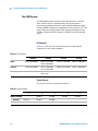
3
Overview
GSM Option is a software for N9360A Multi UE Tester which
supports the signaling tests and the RF performance tests in
inspection processes for production, service, repair and
maintenance.
This product supports the GSM850 band while the GSM900,
DCS1800, and PCS1900 bands are supported by the
conventional Tester. Also, this product newly implements
various functions such as GPRS (General Packet Radio Service)
(CS1, CS2, CS3 and CS4) and SMS (Short Message Service) and
offers major tests with high speed and ease.
This product can carry out the radio performance tests with call
processes. In addition, this product implements TX Analyzer
function to execute RF radio performance tests without call
processes and Signal Generator function used to adjust the
radio parts.
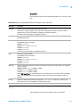
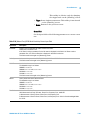
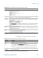
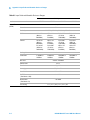
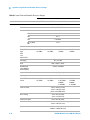
Functions
Table 3-1 shows the functions of this Tester in the GSM Option.
Table 3-1 Main Functions
Function
Description
GSM/GPRS/EGPRS (Option)
Multi band: GSM850, GSM900, DCS1800, PCS1900
Signaling Test
GSM
Location update
MS Call
Talk
RF Test
MS Release
BS Call
BS Release
GPRS
3-2
N9360A Multi UE Tester GSM User Manual
3
Overview
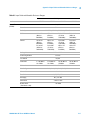
Table 3-1 Main Functions
Function
Description
Attach
Connect
Disconnect
Coding scheme: CS1, CS2, CS3, CS4
Multi slot: 1×1, 2×1, 2×2, 3×1, 3×2, 4×1
(Down×Up)
EGPRS
Attach
Connect
Disconnect
Modulation and Coding scheme: MCS1, MCS2,
MCS3, MCS4 (GMSK)
MCS5, MCS6, MCS7, MCS8, MCS9 (8-PSK)
Puncturing scheme: P1, P2, P3 *
Multi slot: 1×1, 2×1, 2×2, 3×1, 3×2, 4×1
SMS
SMS CB, SMS MT, SMS MO
RF Tests
Peak TX Power
Burst Timing
Power Ramp
Frequency Error
Phase Error (RMS) (Peak) (GMSK)
BER (GSM, GPRS)
BLER (GPRS, EGPRS)
RX Quality
RX Level
FAST BER (GSM)
EVM (RMS, PEAK, 95%) (EGPRS, 8-PSK)
Origin Offset Suppression (EGPRS)
TX Analyzer
Signal Generator
AM Modulation
Frequency Offset
N9360A Multi UE Tester GSM User Manual
3-3
3
Overview
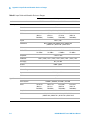
Table 3-1 Main Functions
Function
Description
Remote Control
Ethernet
GP-IB (option)
Serial (option)
* P1, P2 is valid for all. P3 is valid only when the Coding Scheme is set to MCS3, MCS4, MCS7, MCS8, and MCS9.
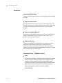
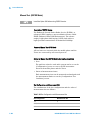
Features
Easy-to-operate Automatic Test
The tests from call processes to the radio performance tests are
executed automatically with easy operation. Each test item in
Automatic Test can be set to either On or Off. Testing time can
be shortened by setting the unnecessary test items to Off.
Shortening of Testing Time
In Automatic Test, tests are executed while preset traffic
channels are automatically handed over. Consequently,
re-testing for each traffic channel is not required and testing
time can be shortened.
Various Test Functions
Besides Automatic Test, Manual Test, Signal Generator and
Spectrum Monitor, functions such as GPRS (CS1, CS2, CS3 and
CS4), EGPRS (Option G03, MCS1-9) and SMS are added to this
product. Therefore, this product can meet the needs in every
inspection process.
Extensive Interfaces
Ethernet, USB, GP-IB and Serial port are prepared. The USB
ports are used to connect a printer or a USB memory device for
firmware update or saving and restoring parameters. Ethernet,
GP-IB, and Serial are used for remote control.
3-4
N9360A Multi UE Tester GSM User Manual
Overview
3
External Control Function (Remote Control)
Remote control is available using Ethernet, GP-IB or Serial.
Each interface port uses the same commands.
An interface port which adapts to user's equipment is
selectable.
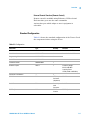
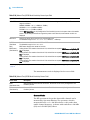
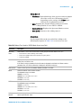
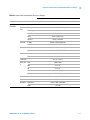
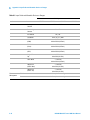
Standard Configuration
Table 3-2 shows the standard configuration of the Tester. Check
the components before using the Tester.
Table 3-2 Configuration
Item name
Type
Quantity
Remarks
GSM Standard
G00 Preinstalled
1
Installed on the Tester
User Manual
N9360A-90700
1
Contained in the CD-R
Programming Manual
N9360A-90702
1
Quick Reference
N9360A-90002
1
Installation Guide
N9360A-90001
1
Antenna coupler
CAU-17
1
Certificate of Calibration
—
1
GP-IB Port
E00
IEEE, 24 pin
Connector
(Amphenol)
GP-IB Port
Serial Port
E01
D-sub 9 pin
male
Connector
Serial Port
EGPRS Option
G03
EGPRS
function
EGPRS Option
N9360A Multi UE Tester GSM User Manual
Frequency Range:
824 to 1990 MHz
Coupling Factor:
15 dB (at 824 to 960 MHz)
3-5
3
Overview
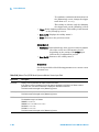
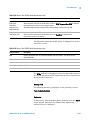
Accessories
Table 3-3 shows the accessories of the Tester. For the
specification of the accessories, contact the Agilent Sales
Department or an approved distributor.
Table 3-3 Accessories
Item Name
Type
Remarks
Test SIM card
—
Test Subscriber Identity Module card
3-6
N9360A Multi UE Tester GSM User Manual
4
Operating Procedures
Test Flow 4-2
Preparation for Each Test
Connection 4-4
Test Procedure 4-5
Ending a Test 4-87
4-3
This chapter describes how to operate the Tester including the
fundamental requirements before starting the tests with the Tester. It also
provides testing examples.
Agilent Technologies
4-1
4
Operating Procedures
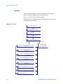
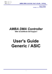
Test Flow
This section describes a test flow to check the mobile phone
with the N9360A GSM Option and GPRS Option.
Figure 4-1 shows the test operation flow.
Subsequently, the mobile phone operation method is described
according to the test flow.
Figure 4-1 Test Flow
2.2.1
System Requirement
2.2.2
Installing the Test SIM
2.2.3
Connection
2.3.1
Activating the Tester
2.3.3 Selection of System
GSM
2.3.4
Selection of the Function Mode on the Initial
Screen
2.3.6
Testing a Dual Band Mobile Phone by
Automatic Test
2.3.7
Testing a Dual Band Mobile Phone by Manual
Test (GSM Mode)
2.3.10
Testing a Mobile Phone by Manual Test
(GPRS Mode)
2.3.11
Testing a Mobile Phone by Manual Test
(EGPRS Mode)
2.3.12
Testing a Mobile Phone by TX Analyzer
WCDMA
W-CDMA System
Refer to the N9360A
GSM User Manual
2.3.13 Testing a Mobile Phone by Signal Generator
2.4
4-2
Ending a Test
N9360A Multi UE Tester GSM User Manual
4
Operating Procedures
Preparation for Each Test
CAUTION
Make sure that the input signal level does not exceed the maximum
level allowed. Otherwise, an accident or Tester failure may occur.
The following procedures are required before starting each test.
System Requirement
The following equipments are required to set up a test system:
• The Agilent N9360A Multi UE Tester.
• An RF cable, RF antenna coupler (type CAU-17) or shield case (part
number 0960-2540) to connect RF signals from/to the mobile phone
under test.
• A printer and a printer cable if required.
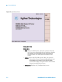
Figure 4-2 Typical Test Setup of the Tester
Installing the Test SIM
Insert the Test Subscriber Identity Module (SIM) provided by
the Agilent Technologies in the mobile phone before performing
any test because the Tester will not be able to perform
measurements with a SIM that is provided by the cell phone
operator or other Test SIMs.
N9360A Multi UE Tester GSM User Manual
4-3
4
Operating Procedures
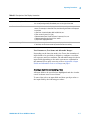
Connection
Connecting a Mobile Phone
Connect a mobile phone to the Tester using any of the following
methods:
1 Using the Antenna Coupler
Connect the Antenna Coupler (type CAU-17) connector to the
RF IN/OUT connector on the front panel of the Tester. Insert the
antenna of the mobile phone into the hole of the Antenna
Coupler.
2 Using a User-Supplied RF Cable
If you have a cable which connects between the mobile phone's
RF port and the RF IN/OUT connector of the Tester, use it
instead of the Antenna Coupler.
3 Using the Shield Case
Connect the ANTENNA COUPLER IN/OUT connector of the
shield case (part number 0960-2540) to the RF IN/OUT
connector on the front panel of the Tester. Place the mobile
phone on the antenna coupler board inside the shield case using
the horizontal and vertical holders.
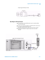
Connecting a Printer / USB Memory Device
1 Printer
To print screen hardcopies, if required, connect a printer to the Tester
as follows using an appropriate interface cable between the USB
connector on the rear panel of the Tester and the USB interface
connector of the printer. Use the recommended printer shown below.
Also, refer to the manual of the printer for operating the printer.
Recommended printer (operation confirmed by Agilent):
EPSON PM-G800
4-4
N9360A Multi UE Tester GSM User Manual
4
Operating Procedures
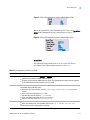
Figure 4-3 Connecting a Printer
2 USB Memory Device
To save graphic files of screen in a USB memory device, connect the
USB memory device to the USB connector on the front panel of the
Tester. Graphic files are saved in Portable Network Graphics (PNG)
format and with a file name: COPY and the number from 00 to 99
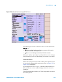
which automatically increases.
Test Procedure
Activating the Tester
To activate the Tester, turn on the Line switch on the rear panel
of the Tester and press the LINE switch on the front panel.
NOTE
Provide warm up of 30 minutes or more to ensure correct measurement.
General Operation
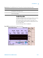
Display Annotation
N9360A Multi UE Tester GSM User Manual
4-5
4
Operating Procedures
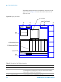
Depending on functions and test situations, there are several
types of screen. Figure 4-4 shows the common areas on the
typical screen.
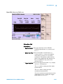
Figure 4-4 Display Annotation
a) Test Flow
‡
1
Automatic
Test
‡
2
Stand-by
b) Test Results
‡
3
2037/12/31
‡
4
23:59
‡5
c) Measurement Item
d) Measurement Result
e) Input Field
‡6
Press [Start] to begin a test.
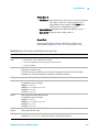
Table 4-1 Description of the Display Annotation
No.
4-6
Name
Description
1
Function Mode Field
The current function mode is displayed in this field.
2
Status Display Field
The current operation status in the Automatic Test, Manual Test, TX Analyzer
and Configuration are displayed in this field. This status includes Stand-by,
Measuring, Test Condition and Test Sequence.
3
Date/Time Field
The current date and time are displayed in this field.
N9360A Multi UE Tester GSM User Manual
4
Operating Procedures
Table 4-1 Description of the Display Annotation
No.
Name
Description
4
Softkey Menu Field
The softkey labels are displayed in this field. Each label defines the function of
the corresponding softkey immediately next to the right of the label.
5
Screen Field
A variety of information is displayed in this field depending on the operation
status. For example, in Automatic Test, the following information is displayed
in this field.
a) Test Flow: Location Update, MS Call, BS Call, etc.
b) Test results: P (pass) or F (fail).
c) Measurement Items: Peak TX Power, Frequency Error, etc.
d) Measurement Results: Pass/Fail or values.
e) Input field: Highlighted fields.
6
Message Field
Operation message for test flow steps are displayed in this field.
In this field, the word surrounded by bracket denotes the softkey.
Test Parameters, Test Items and Allowable Ranges
Depending on the function modes, the Tester has a number of
input fields to be specified or defined to configure a test flow,
test sequence and test condition. The allowable ranges for those
input fields depending on the radio systems are explained in
this manual. For a quick overview, refer to Appendix A Input
Fields and Allowable Choices or Ranges on page 1.
Selecting an Input Field and Specifying a Value
All input fields to be specified are highlighted and the circular
cursor is shown next to one of them.
To start, first select an input field and then specify a value to
the input field by the following procedure:
N9360A Multi UE Tester GSM User Manual
4-7
4
Operating Procedures
Step 1
Rotate the CURSOR CONTROL knob clockwise to move the
cursor downward or right, or rotate it counterclockwise to move
it upward or left, and place it next to the input field you want to
change.
Step 2
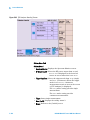
Press the CURSOR CONTROL knob once. The highlighted input
field changes to normal display and circular cursor changes to a
triangular one.
Step 3
Rotate the CURSOR CONTROL knob clockwise or
counterclockwise to find the values defined for it.
Step 4
Press the CURSOR CONTROL knob to enter the desired value in
the input field. The input field is highlighted again and the
triangular cursor returns to the circular one.
Storing Numeric Values
4-8
N9360A Multi UE Tester GSM User Manual
4
Operating Procedures
For numeric input fields such as channel numbers and
relevancies of amplitude, you can store up to four numeric
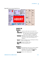
values into the memory softkey menus with the following
procedure:
Step 1
Move the cursor to one of the numeric input fields of channels
and relevancies of amplitude.
Step 2
Press the CURSOR CONTROL knob to select the field. The
softkey menu as Figure 4-5 is displayed on the screen. The four
memory softkeys show the values previously stored in the
memories if any.
Figure 4-5 Value Storage Softkeys
N9360A Multi UE Tester GSM User Manual
4-9
4
Operating Procedures
Step 3
Set a numeric value in the input field with the CURSOR
CONTROL knob.
Step 4
Press the Store Value to Memory >> softkey. The softkey menu
including Memory 1, Memory 2, Memory 3 and Memory 4 softkeys as
shown in Figure 4-6.
Figure 4-6 Memory Function
Step 5
Press either of the memory softkeys from 1 to 4 where you
desire to store that value.
4-10
N9360A Multi UE Tester GSM User Manual
4
Operating Procedures
Step 6
The memory softkey menu returns to the state in Step 2 showing
the value newly stored.
Step 7
Press the CURSOR CONTROL knob to set the value into the
field. The softkey menu returns to that of Step 1.
Step 8
Repeat the procedure from Step 1 to Step 7, if required.
Recalling Numeric Values
Step 1
Move the cursor to one of the numeric input fields of channels
or relevancies of amplitude.
Step 2
Press the CURSOR CONTROL knob to select the field. The
softkey menu displayed as shown in Figure 4-7. The four
memory softkeys show the values previously stored in the
memories if any.
N9360A Multi UE Tester GSM User Manual
4-11
4
Operating Procedures
Figure 4-7 Value Storage Softkeys
Step 3
Press Memory 1, Memory 2, Memory 3 or Memory 4 softkey to enter
the stored value to the field.
Step 4
The value is entered to the field.
Step 5
Press the CURSOR CONTROL knob to return the softkey menu
to that of Step 1.
4-12
N9360A Multi UE Tester GSM User Manual
4
Operating Procedures
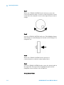
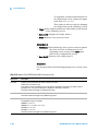
Changing Magnification Softkey
Press the CURSOR CONTROL knob to select a numeric input
field, such as channels and relevancies of amplitude. A changing
magnification softkey as in Figure 4-8 is displayed with memory
softkeys. A selected magnification is underlined.
Figure 4-8 Changing Magnification Softkey
Pressing this softkey changes the multiplier from 1 to 1000.
Rotating the CURSOR CONTROL knob clockwise changes the
numeric value in the field by an increment, and
counterclockwise changes the value by a decrement. The
following multiplies are variable.
• ×1: Increment or decrement by 1.
• ×10: Increment or decrement by 10.
• ×100: Increment or decrement by 100.
• ×1000: Increment or decrement by 1000.
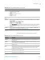
Selection of System
On this screen, select a system from GSM and W-CDMA.
NOTE
This N9360A GSM User Manual describes only the GSM system. Refer to
the N9360A W-CDMA User Manual about the W-CDMA system.
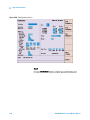
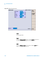
Turn on the Tester. The [Top Menu] screen is displayed as
Figure 4-9.
N9360A Multi UE Tester GSM User Manual
4-13
4
Operating Procedures
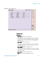
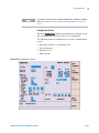
Figure 4-9 [Top Menu] Screen
Step 1
Press the GSM softkey to select the GSM system. The [Initial]
screen for GSM is displayed after the Tester completes its
initialization and self-test routine.
4-14
N9360A Multi UE Tester GSM User Manual
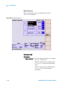
4
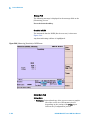
Operating Procedures
Figure 4-10 [Initial] Screen
NOTE
When the Autoboot function is set to GSM or WCDMA and not to None, the
Tester will automatically enter the GSM or W-CDMA system mode if no
softkey is pressed within the specified time (10 to 60 seconds). When the
Tester is shipped, the AutoBoot function is set to None. For details, see
AutoBoot on page 8.
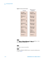
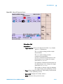
Selection of the Function Mode on the Initial Screen
The Tester executes its initialization and self-test routine after
completion of system setting. The [Initial] screen is displayed
subsequently.
Press one of the softkeys to select a function mode.
N9360A Multi UE Tester GSM User Manual
4-15
4
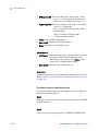
Operating Procedures
Figure 4-11 [Initial] Screen
Softkey Menu Field
Softkey menu
Automatic Test: Starts the Automatic Test. Refer to Testing a Dual
Band Mobile Phone by Automatic Test on page 22.
Manual Test: Starts the Manual Test. Refer to Testing a Dual Band
Mobile Phone by Manual Test (GSM Mode) on page 31 for GSM
mode, and Testing a Mobile Phone by Manual Test (GPRS Mode) on
page 55 for GPRS mode.
TX Analyzer: Starts the TX Analyzer test. Refer to Testing a Mobile
Phone by TX Analyzer on page 75.
Signal Generator: Starts the Signal Generator. Refer to Testing a
Mobile Phone by Signal Generator on page 83.
Return to Menu: This softkey is not for selecting a function mode.
The screen returns to the [Top Menu] screen when this softkey
is pressed. Refer to Return to Menu Screen on page 15 for detail.
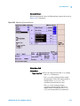
Configuration: Go to the [Configuration] screen to set the
parameters. Refer to Configuration on page 168.
4-16
N9360A Multi UE Tester GSM User Manual
4
Operating Procedures
Correction
Actual Input/Output Level and Correction
1 Actual Output Level and Correction in Automatic Test (Except RF
test), Manual Test, and Signal Generator
Output signal level of the Tester is corrected according to cable loss,
coupling loss, and etc. Some of parameters should be set properly.
Actual output level (for downlink signal) at the RF IN/OUT connector
in the Automatic Test mode (except RF test), the Manual Test mode
and the Signal Generator mode is calculated by the following equation.
OutputLevel = BsLevel + LossRFOut
Where,
OutputLevel = Actual output level at the RF IN/OUT connector.
BsLevel = Setting value at the BS Level, BER BS Level and BLER BS
Level field on the [Configuration: Test Condition] screen or
the Amplitude field on the [Signal Generator] screen.
LossRfOut = Setting value at the LOSS/RF Out field on the
[Configuration] screen.
There is a restriction that the OutputLevel cannot exceed –20.0 dBm,
so at each parameter, the BsLevel and the LossRfOut must be set to
meet this restriction.
2 Actual Input Signal Level and Correction in Automatic Test (Except
RF test), Manual Test, and TX Analyzer
Input signal level of the Tester (for uplink signal) is corrected
according to cable loss, coupling loss, and etc. Some of parameters
should be set properly.
The measurement results of RF test in the Manual Test mode and the
TX Analyzer mode are corrected by the following equation.
InputLevel = MsLevel + LossRFIn
Where,
InputLevel = Corrected measured value of the Tester.
MsLevel = Input signal level of the mobile phone at the RF IN/OUT
connector.
N9360A Multi UE Tester GSM User Manual
4-17
4
Operating Procedures
LossRfIn = Setting value at the LOSS/RF In field on the [Configuration]
screen.
3 Actual Output Level and Correction for RF Test in Automatic Test
Output signal level of the Tester is corrected according to cable loss,
coupling loss, and etc. Some of parameters should be set properly.
Actual output level (for downlink signal) at the RF IN/OUT connector
for RF test in the Automatic Test mode is calculated by the following
equation.
OutputLevel = BsLevel + LossRFOut + AttOut
Where,
OutputLevel = Actual output level at the RF IN/OUT connector.
BsLevel = Setting value at the BS Level, BER BS Level and BLER BS
Level field on the [Configuration: Test Condition] screen.
LossRfOut = Setting value at the LOSS/RF Out field on the
[Configuration] screen.
AttOut = Setting value at the ATT Out field on the [Configuration: Test
Sequence] screen.
There are two restrictions. The OutputLevel cannot exceed –20.0 dBm,
so each parameter, the BsLevel, the LossRfOut and the ATT Out, must
be set to meet this restriction. The other restriction is that the sum of
the LossRfOut and the ATT Out must be set more than or equal to 0.
4 Actual Input Signal Level and Correction for RF Test in Automatic
Test
Input signal level of the Tester is corrected according to cable loss,
coupling loss, and etc. Some of parameters should be set properly.
The measurement results of RF test in the Automatic Test mode are
corrected by the following equation.
InputLevel = MsLevel + LossRFIn + AttIn
Where,
InputLevel = Corrected measured value of the Tester.
MsLevel = Input signal level of the mobile phone at the RF IN/OUT
connector.
4-18
N9360A Multi UE Tester GSM User Manual
Operating Procedures
4
LossRfIn = Setting value at the LOSS/RF IN field on the [Configuration]
screen.
AttIn = Setting value at the ATT In field on the [Configuration: Test
Sequence] screen.
There is a restriction that the sum of the LossRfIn and ATT In must be
set more than or equal to 0.
Entering Loss in Configuration
Determine and enter the loss values caused by the antenna
coupler, RF cable, or shield case used to connect the mobile
phone to the Tester. If the Loss is set to On, these path loss
values are applied to all through the test flow for the radio
system being currently tested.
Correction of input/output signal is described in Actual
Input/Output Level and Correction on page 17. Also, refer to Entering
Channel Attenuations on the Configuration: Test Sequence Screen on
page 20 for the correction of RF test in Automatic Test.
Step 1
Press the GSM softkey on the [Top Menu] screen to activate the
GSM system. Refer to Selection of System on page 13 for detail.
Step 2
Press the Config softkey on the [Initial] screen to display the
[Configuration] screen.
N9360A Multi UE Tester GSM User Manual
4-19
4
Operating Procedures
Figure 4-12 [Configuration] Screen
Step 3
Set the Loss field to On with the CURSOR CONTROL knob.
Step 4
Enter the appropriate loss values, depending on the radio
systems, in the RF In and RF Out fields with the CURSOR
CONTROL knob. These loss values are used all through the test
flow.
Step 5
Press the Return softkey to return to the [Initial] screen.
Entering Channel Attenuations on the Configuration: Test Sequence Screen
4-20
N9360A Multi UE Tester GSM User Manual
4
Operating Procedures
This section describes correction for RF test results in
Automatic Test. Each traffic channel (TCH) path loss can be set
on the [Configuration: Test Sequence] screen. This is the RF test
correction function in addition to the loss function in the
[Configuration] screen.
In addition to entering the loss values on the [Configuration]
screen, you can also enter the attenuation values to be used to
correct the RF test results with these values at each traffic
channel in the Automatic Test mode.
Determine and enter the appropriate attenuation values at each
traffic channel with the following procedure, caused by the
antenna coupler, RF cable or shield case to connect the mobile
phone to the Tester.
Step 1
Press the GSM softkey on the [Top Menu] screen to activate GSM
system. Refer to Selection of System on page 13 for detail.
Step 2
Press the Config softkey on the [Initial] screen, and then the Test
Sequence softkey to display the [Configuration: Test Sequence]
screen.
N9360A Multi UE Tester GSM User Manual
4-21
4
Operating Procedures
Figure 4-13 [Configuration: Test Sequence] Screen
Step 3
Enter the appropriate attenuation values, depending on the
traffic channel, in the ATT In and ATT Out fields with the
CURSOR CONTROL knob. These values are effective for the RF
tests in the test flow.
Step 4
Press the Return softkey twice to return to the [Initial] screen.
Testing a Dual Band Mobile Phone by Automatic Test
This section describes the operation method of the Tester and a
dual band (GSM900 and DCS1800) mobile phone under the test
by Automatic Test.
4-22
N9360A Multi UE Tester GSM User Manual
Operating Procedures
4
Step 1
Turn on the Tester and select the GSM system on the [Top
Menu] screen. Refer to Selection of System on page 13 for
selecting a system.
Step 2
The [Initial] screen as Figure 4-14 is displayed after completion
of initialization and self-test routine of the Tester.
Figure 4-14 [Initial] Screen
Step 3
Press the Config softkey on the [Initial] screen to display the
[Configuration] screen for specifying the Loss field.
N9360A Multi UE Tester GSM User Manual
4-23
4
Operating Procedures
Figure 4-15 [Configuration] Screen
Step 4
Press the Test Sequence softkey to display the [Configuration:
Test Sequence] screen for required setting in Automatic Test.
4-24
N9360A Multi UE Tester GSM User Manual
4
Operating Procedures
Figure 4-16 [Configuration: Test Sequence] Screen
Step 5
Set GSM900 and DCS1800 in Radio System 1 and 2, respectively,
and set other fields as shown in Figure 4-16.
Step 6
Set Run at test item field which you want to execute in the test
flow.
Step 7
Set Run at measurement item cell which you want to measure in
the measurement item table.
N9360A Multi UE Tester GSM User Manual
4-25
4
Operating Procedures
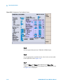
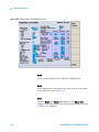
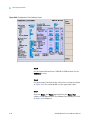
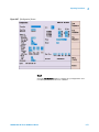
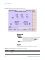
Step 8
Press the Return and then the Test Condition softkey to display the
[Configuration: Test Condition] screen as Figure 4-17 to set the
test condition.
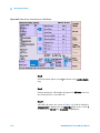
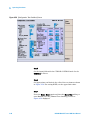
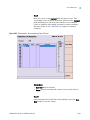
Figure 4-17 [Configuration: Test Condition] Screen
Step 9
Set the fields of the test parameters as shown in the left side of
Figure 4-17 with the CURSOR CONTROL knob.
Step 10
Set appropriate test limits in the cells of the test item table in
the right side of Figure 4-17.
Step 11
Repeat Step 10 to Step 11 to set the test condition for DCS1800
after replacing GSM900 and DCS1800 in Radio System field.
4-26
N9360A Multi UE Tester GSM User Manual
Operating Procedures
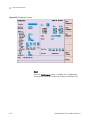
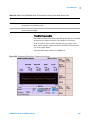
4
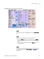
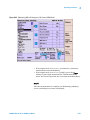
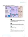
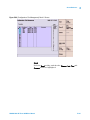
Step 12
Press the Return softkey twice and then the Automatic Test softkey
to start Automatic Test. The [Automatic Test: Stand-by] screen
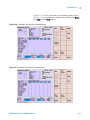
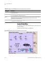
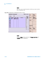
as Figure 4-18 is displayed.
Figure 4-18 [Automatic Test: Stand-by] Screen
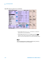
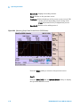
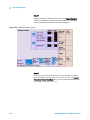
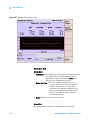
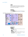
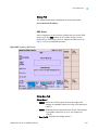
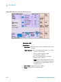
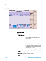
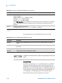
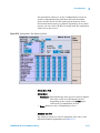
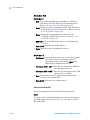
Step 13
Press the Screen>> softkey to select the display mode. Select
Simple, Detail or Value softkey. The following Figure 4-19 is a value
screen which will show a measured value for each measurement
item.
N9360A Multi UE Tester GSM User Manual
4-27
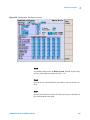
4
Operating Procedures
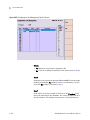
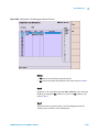
Figure 4-19 [Automatic Test: Stand-by] Value Screen
Step 14
Press the Start softkey to start a test. A screen status changes
from Stand-by to Measuring.
Step 15
Turn the mobile phone on. Wait for the mobile phone to camp
on, and P is shown at the Location Update step.
Step 16
At the MS Call step, make a call from the mobile phone. Dial an
arbitrary number and press the Off Hook button on the mobile
phone.
Step 17
At the Talk step, check the quality of loop back voice and press
the Pass or the Fail softkey according to its result.
4-28
N9360A Multi UE Tester GSM User Manual
4
Operating Procedures
Step 18
As each step is running in the test flow, its corresponding test
item field in the table is highlighted. While the RF Test step is
blinking, each of the measurement items is measured. So, you
can see how it is being done.
Step 19
At the MS Release step, press the On Hook button on the mobile
phone to finish the call.
Step 20
At the BS Call step, press the Off Hook button on the mobile phone
to respond to the call from the Tester.
Step 21
If the sequence 2 is set on the [Configuration: Test Sequence]
screen, the sequence 2 is executed automatically after the BS
Release step in the sequence 1 is completed. The test goes on in
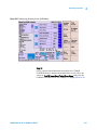
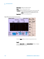
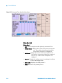
the same way as sequence 1.
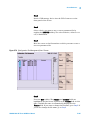
Step 22
After the measurement is completed, a [Stand-by] summary
screen is displayed to show the test results.
N9360A Multi UE Tester GSM User Manual
4-29
4
Operating Procedures
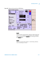
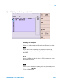
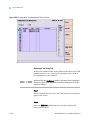
Figure 4-20 [Stand-by] Summary Screen
Step 23
If a printer is available, print the test results. Press the More (1 of
2), and then the Print Screen softkey to print a screen hardcopy.
Step 24
Press the More (2 of 2) softkey to return to the previous softkey
menu.
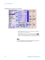
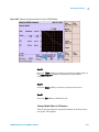
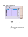
Step 25
Place the circular cursor at a value, Pass or Fail of any channel
in the Burst Timing or Power Ramp cell, for example, then press the
CURSOR CONTROL knob to display the Graph/Value screen as
Figure 4-21. See where the marker appears in the graph, and the
failed result data is shown if any (highlighted in this text).
4-30
N9360A Multi UE Tester GSM User Manual
4
Operating Procedures
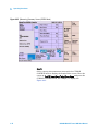
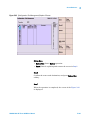
Figure 4-21 [Stand-by] Graph/Value Screen
Step 26
Press the Return softkey to return to the previous screen. The
Graph/Value screen for other measurement items can be
displayed in the same method.
Step 27
If you want to repeat the same test again, press the Start softkey.
Testing a Dual Band Mobile Phone by Manual Test (GSM Mode)
This section describes the operation method of the Tester and a
dual band (GSM900 and DCS1800) mobile phone under the test
by the Manual Test GSM mode.
N9360A Multi UE Tester GSM User Manual
4-31
4
Operating Procedures
Step 1
Turn on the Tester and select the GSM system on the [Top
Menu] screen. Refer to Selection of System on page 13 for
selecting a system.
Step 2
The [Initial] screen as Figure 4-22 is displayed after completion
of initialization and self-test routine of the Tester.
Figure 4-22 [Initial] Screen
Step 3
Press the Config softkey on the [Initial] screen to display the
[Configuration] screen for specifying the Loss field.
4-32
N9360A Multi UE Tester GSM User Manual
Operating Procedures
4
Figure 4-23 [Configuration] Screen
Step 4
Press the Test Condition softkey to display the [Configuration:
Test Condition] screen for required setting in Manual Test GSM
mode.
N9360A Multi UE Tester GSM User Manual
4-33
4
Operating Procedures
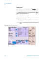
Figure 4-24 [Configuration: Test Condition] Screen
Step 5
Set the input fields with the CURSOR CONTROL knob.
Step 6
Set the appropriate test limits in the cells of the test item table
in the right side of the Figure 4-24.
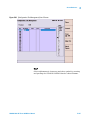
Step 7
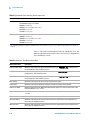
Press the Return, and Return again and then the Manual Test
softkey to start Manual Test. The [Manual Test: Stand-by] screen
as Figure 4-25 is displayed.
4-34
N9360A Multi UE Tester GSM User Manual
4
Operating Procedures
Figure 4-25 [Manual Test: Stand-by] Screen (GSM Mode)
Step 8
Turn the mobile phone on and wait for it to camp on, and P is
shown at the Location Update step.
Step 9
Start MS Call or BS Call with the following operation.
• Dial an arbitrary number and press the Off Hook button on the
mobile phone.
• Press the BS Call softkey to start BS Call. Press Off Hook button
on the mobile phone to respond to the call from the Tester.
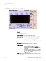
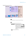
Step 10
After MS call or BS call starts, the screen as Figure 4-26 will be
displayed. P is shown at the MS Call or BS Call step, and Connection
is highlighted.
N9360A Multi UE Tester GSM User Manual
4-35
4
Operating Procedures
Figure 4-26 [Measuring] MS Call Screen (GSM Mode)
• If the trigger mode is set to Cont (continuous), continuous
measurement starts immediately.
• If the trigger mode is set to Sing (single), press the Trigger
softkey to start single measurement. Until measurement
starts, the Tester loops back the voice from the mobile phone.
Step 11
After the measurement is completed, a [Measuring] summary
screen containing test results is displayed.
4-36
N9360A Multi UE Tester GSM User Manual
4
Operating Procedures
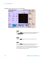
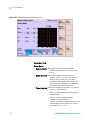
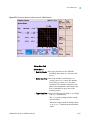
Figure 4-27 [Measuring] Summary Screen (GSM Mode)
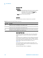
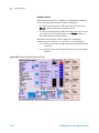
Step 12
Select a group of measurement items with the CURSOR
CONTROL knob to display the Graph/Value screen. Place the
cursor at Peak TX Power/Burst Timing/Power Ramp and press the
CURSOR CONTROL knob, for example, to display Figure 4-28.
N9360A Multi UE Tester GSM User Manual
4-37
4
Operating Procedures
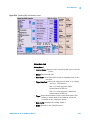
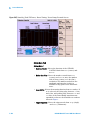
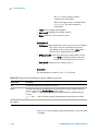
Figure 4-28 [Measuring] Graph/ Value Screen (GSM Mode)
Step 13
Press a softkey as needed.
Knob Cur/Marker: Selects the cursor or the marker.
Marker Coar/Fine: Selects the marker control from Coar (coarse)
and Fine to move the marker with 10 dots
(coarse) or 1 dot (fine) resolution. The
marker readout for the amplitude and
timeslot (in bits) is available at any point of
the measurement trace.
Zoom Off/On: Selects the zoom mode from On and Off.
Trigger Sing/Cont: Selects the trigger mode from Sing to Cont.
•When the trigger mode is Sing, single
measurement starts after the Trigger softkey
is pressed.
•To change the trigger mode to Cont in order
to start continuous measurement, press the
Trigger Sing/Cont softkey.
Trigger: Starts single measurement when the trigger mode is set
to Sing.
4-38
N9360A Multi UE Tester GSM User Manual
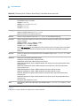
Operating Procedures
4
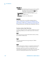
More (1 of 2): Displays the softkey menu 2.
Return: Returns to the previous screen.
Print Screen: Prints a hardcopy of the screen or saves it in a USB
memory device depending on the setting of the
Printer input field on the [Configuration] screen.
More (2 of 2): Returns to the softkey menu 1.
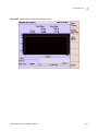
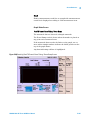
Figure 4-29 [Measuring] Graph/Value Zoomed Screen (GSM Mode)
Press the Return softkey to return to the previous screen.
Step 14
Press the More (1of 2) and the Spectrum Monitor softkey to display
the Spectrum Monitor screen.
N9360A Multi UE Tester GSM User Manual
4-39
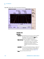
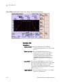
4
Operating Procedures
Figure 4-30 [Measuring] Spectrum Monitor Screen (GSM Mode)
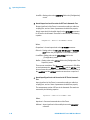
Step 15
Press the Trigger softkey to measure spectrum in single mode or
the Trigger Sing/Cont softkey to measure the spectrum in
continuous mode.
Step 16
Press the Return softkey to return to the previous screen.
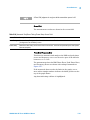
Step 17
Press the Release softkey to start BS release, or press the On
Hook button on the mobile phone to start MS release.
After the release process is completed, the screen will return to
the [Stand-by] screen. You can also display a Graph/Value
screen from the [Stand-by] screen.
4-40
N9360A Multi UE Tester GSM User Manual
Operating Procedures
4
Figure 4-31 [Stand-by] After Release Screen (GSM Mode)
Handover
Step 1
Turn on the Tester and select the GSM system on the [Top
Menu] screen. Refer to Selection of System on page 13 for
selecting a system.
Step 2
The [Initial] screen as Figure 4-32 is displayed after completion
of initialization and self-test routine of the Tester.
N9360A Multi UE Tester GSM User Manual
4-41
4
Operating Procedures
Figure 4-32 [Initial] Screen
Step 3
Press the Config softkey on the [Initial] screen to display the
[Configuration] screen for specifying the Loss field.
4-42
N9360A Multi UE Tester GSM User Manual
Operating Procedures
4
Figure 4-33 [Configuration] Screen
Step 4
Press the Test Condition softkey to display the [Configuration: Test
Condition] screen for required setting in Manual Test GSM mode.
N9360A Multi UE Tester GSM User Manual
4-43
4
Operating Procedures
Figure 4-34 [Configuration: Test Condition] Screen
Step 5
Set the input fields with the CURSOR CONTROL knob.
Step 6
Set the appropriate test limits in the cells of the test item table
in the right side of the Figure 4-34
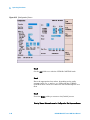
Step 7
Press the Return, and Return again and then the Manual Test
softkey to start Manual Test. The [Manual Test: Stand-by] screen
as Figure 4-35 displayed.
4-44
N9360A Multi UE Tester GSM User Manual
4
Operating Procedures
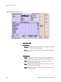
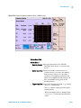
Figure 4-35 [Manual Test: Stand-by] Screen (GSM Mode)
Step 8
Turn the mobile phone on and P is shown at the Location Update
step.
Step 9
Start BS Call or MS Call with the following operation.
• Press the BS Call softkey to start BS Call. Press the Off Hook
button on the mobile phone to respond to the call from the
Tester.
• Dial an arbitrary number and press the Off Hook button on
the mobile phone.
Step 10
After MS call or BS Call starts, the screen as Figure 4-36 will be
displayed. P is shown in the MS Call, BS Call and Connection step is
highlighted.
N9360A Multi UE Tester GSM User Manual
4-45
4
Operating Procedures
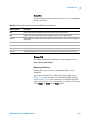
Figure 4-36 [Measuring] BS Call Screen (GSM Mode)
• If the trigger mode is set to Cont (continuous), continuous
measurement starts immediately.
• If the trigger mode is set to Sing (single), press the Trigger
softkey to start single measurement. Until measurement
starts, the Tester loops back the voice from the mobile phone.
Step 11
After the measurement is completed, a [Measuring] summary
screen containing test results is displayed.
4-46
N9360A Multi UE Tester GSM User Manual
4
Operating Procedures
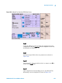
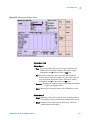
Figure 4-37 [Measuring] Summary Screen (GSM Mode)
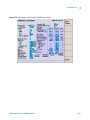
Step 12
Change the channel with the following operation.
Move the cursor to TCH input field and press the CURSOR
CONTROL knob. Rotate the CURSOR CONTROL knob to select
the channel for handover. Press the CURSOR CONTROL knob.
Then, the Handover step is highlighted and the channel changes
to the selected channel. When handover is completed, P is
shown at the Handover step.
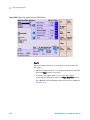
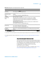
Step 13
Press the Release softkey to start BS release, or press the On
Hook button on the mobile phone to start MS release.
After the release process is completed, the screen will return to
the [Stand-by] screen. You can also display a [Graph/Value]
screen from the [Stand-by] screen.
N9360A Multi UE Tester GSM User Manual
4-47
4
Operating Procedures
Figure 4-38 [Stand-by] After Release Screen (GSM Mode)
Emergency Call
NOTE
To test the emergency call function, place the mobile phone and the
Tester where the radio signal (electromagnetic wave) from base station of
a cell phone operator does not propagate, such as in a shield room, an
anechoic chamber, and etc.
Execute the test of emergency call without any SIM.
Step 1
Turn on the Tester and select the GSM system on the [Top
Menu] screen. Refer to Selection of System on page 13 for
selecting a system.
Step 2
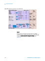
The [Initial] screen as Figure 4-39 is displayed after completion
of initialization and self-test routine of the Tester.
4-48
N9360A Multi UE Tester GSM User Manual
Operating Procedures
4
Figure 4-39 [Initial] Screen
Step 3
Press the Config softkey on the [Initial] screen to display the
[Configuration] screen for specifying the Loss field.
N9360A Multi UE Tester GSM User Manual
4-49
4
Operating Procedures
Figure 4-40 [Configuration] Screen
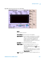
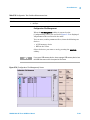
Step 4
Press the Test Condition softkey to display the [Configuration: Test
Condition] screen for required setting in Manual Test GSM mode.
4-50
N9360A Multi UE Tester GSM User Manual
4
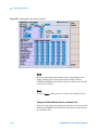
Operating Procedures
Figure 4-41 [Configuration: Test Condition] Screen
Step 5
Set the input fields with the CURSOR CONTROL knob.
Step 6
Set the appropriate test limits in the cells of the test item table
in the right side of the Figure 4-41
Step 7
Press the Return, and Return again and then the Manual Test
softkey to start Manual Test. The [Manual Test: Stand-by] screen
as Figure 4-42 displayed.
N9360A Multi UE Tester GSM User Manual
4-51
4
Operating Procedures
Figure 4-42 [Manual Test: Stand-by] Screen (GSM Mode)
Step 8
Turn the mobile phone on and P is shown at the Location Update
step.
Step 9
Dial an emergency call number and press the Off Hook button on
the mobile phone to start MS Call.
Step 10
After MS call starts, the screen as Figure 4-43 will be displayed.
Emergency Call is displayed at the Dialed No.: field on the screen. P
is shown in the MS Call and Connection is highlighted.
4-52
N9360A Multi UE Tester GSM User Manual
4
Operating Procedures
Figure 4-43 [Measuring] MS Call Emergency Call Screen (GSM Mode)
• If the trigger mode is set to Cont (continuous), continuous
measurement starts immediately.
• If the trigger mode is set to Sing (single), press the Trigger
softkey to start single measurement. Until measurement
starts, the Tester loops back the voice from the mobile phone.
Step 11
After the measurement is completed, a [Measuring] summary
screen containing test results is displayed.
N9360A Multi UE Tester GSM User Manual
4-53
4
Operating Procedures
Figure 4-44 [Measuring] Emergency Call Summary Screen (GSM Mode)
Step 12
Press the Release softkey to start BS release, or press the On Hook
button on the mobile phone to start MS release.
After the release process is completed, the screen will return to
the [Stand-by] screen. You can also display a Graph/Value
screen from the [Stand-by] screen.
4-54
N9360A Multi UE Tester GSM User Manual
Operating Procedures
4
Figure 4-45 [Stand-by] After Release Screen (GSM Mode)
Testing a Mobile Phone by Manual Test (GPRS Mode)
This section describes the operation method of the Tester and a
mobile phone under the test by the Manual Test GPRS mode.
Step 1
Turn on the Tester and select the GSM system on the [Top
Menu] screen. Refer to Selection of System on page 13 for
selecting a system.
Step 2
The [Initial] screen as Figure 4-46 is displayed after completion
of initialization and self-test routine of the Tester.
N9360A Multi UE Tester GSM User Manual
4-55
4
Operating Procedures
Figure 4-46 [Initial] Screen
Step 3
Press the Config softkey on the [Initial] screen to display the
[Configuration] screen for specifying the Loss field.
4-56
N9360A Multi UE Tester GSM User Manual
Operating Procedures
4
Figure 4-47 [Configuration] Screen
Step 4
Press the Test Condition softkey to display the [Configuration: Test
Condition] screen for required setting in Manual Test GPRS mode.
N9360A Multi UE Tester GSM User Manual
4-57
4
Operating Procedures
Figure 4-48 [Configuration: Test Condition] Screen
Step 5
Set the input fields with the CURSOR CONTROL knob. Set the
GSM Mode to GPRS.
Step 6
Set appropriate test limits in the cells of the test items as shown
in Figure 4-48. For testing BLER, set the upper limit value.
Step 7
Press the Return, and Return again and then the Manual Test
softkey to start Manual Test. The [Manual Test: Stand-by] screen
as Figure 4-49 displayed.
4-58
N9360A Multi UE Tester GSM User Manual
4
Operating Procedures
Figure 4-49 [Manual Test: Stand-by] GPRS Mode Screen
Step 8
Check the difference in the test flow, the parameters for slot
configuration, and the Sensitivity field as compared to those for
the Manual test GSM mode.
Step 9
Specify the input fields of the test parameters as shown in
Figure 4-49.
Step 10
Turn the mobile phone on and wait for it to camp on, and P is
shown in the Attach step.
Step 11
Upon completion of the attaching process, the [Manual Test:
Measuring] screen is displayed as shown in Figure 4-50.
N9360A Multi UE Tester GSM User Manual
4-59
4
Operating Procedures
Figure 4-50 [Measuring] Attached Screen (GPRS Mode)
Step 12
When the attached process is succeeded, the Tester waits for
the trigger.
• When the trigger mode is Sing, single measurement will start
after the Trigger softkey is pressed.
• To change the trigger mode to Cont in order to start
continuous measurement, press the Trigger Sing/Cont softkey.
The [Manual Test: Measuring] connected screen is displayed
as Figure 4-51.
4-60
N9360A Multi UE Tester GSM User Manual
4
Operating Procedures
Figure 4-51 [Measuring] Connected Screen (GPRS Mode)
Step 13
During continuous measurement, change the trigger mode from
Cont to Sing to terminate the measurement. Upon completion
of the measurement at the Connected step, the step proceeds to
the Disconnect step.
Step 14
The screen automatically changes to a [Measuring] summary
screen containing test results.
N9360A Multi UE Tester GSM User Manual
4-61
4
Operating Procedures
Figure 4-52 [Measuring] Summary Screen (GPRS Mode)
Step 15
Select a group of measurement items with the CURSOR
CONTROL knob to display the Graph/Value screen. Place the
cursor at Peak TX Power/Burst Timing/Power Ramp and press the
CURSOR CONTROL knob, for example, to display the
Figure 4-53.
4-62
N9360A Multi UE Tester GSM User Manual
4
Operating Procedures
Figure 4-53 [Measuring] Graph/Value Screen (GPRS Mode)
Step 16
Press a softkey as needed.
Knob Cur/Marker: Selects the cursor or the marker.
Marker Coar/Fine: Selects the marker control from Coar (coarse)
and Fine to move the marker with 10 dots
(coarse) or 1 dot (fine) resolution. The
marker readout for the amplitude and
timeslot (in bits) is available at any point of
the measurement trace.
Zoom Off/On: Selects the zoom mode from On and Off.
Trigger Sing/Cont: Selects the trigger mode from Sing to Cont.
•When the trigger mode is Sing, single
measurement starts after the Trigger softkey
is pressed.
•To change the trigger mode to Cont in order
to start continuous measurement, press the
Trigger Sing/Cont softkey.
Trigger: Starts single measurement when the trigger mode is set
to Sing.
N9360A Multi UE Tester GSM User Manual
4-63
4
Operating Procedures
More (1 of 2): Displays the softkey menu 2.
Return: Returns to the previous screen.
Print Screen: Prints a hardcopy of the screen or saves it in a USB
memory device depending on the setting of the
Printer input field on the [Configuration] screen.
More (2 of 2): Returns to the softkey menu 1.
Figure 4-54 [Measuring] Graph/Value Zoomed Screen (GPRS Mode)
Press the Return softkey to return to the previous screen.
Step 17
Press the More (1 of 2) and the Spectrum Monitor softkey to display
the Spectrum Monitor screen.
4-64
N9360A Multi UE Tester GSM User Manual
Operating Procedures
4
Figure 4-55 [Measuring] Spectrum Monitor Screen (GPRS Mode)
Step 18
Press the Trigger softkey to measure spectrum in single mode, or
the Trigger Sing/Cont softkey to measure the spectrum in
continuous mode.
Step 19
Press the Return softkey to return to the previous screen.
Step 20
Press the End softkey to finish the test.
Testing a Mobile Phone by Manual Test (EGPRS Mode)
This section describes the operation method of the Tester and a
mobile phone under the test by the Manual Test EGPRS mode.
N9360A Multi UE Tester GSM User Manual
4-65
4
Operating Procedures
NOTE
Install the Option G03 before using EGPRS function.
Step 1
Turn on the Tester and select the GSM system on the [Top
Menu] screen. Refer to Selection of System on page 13 for
selecting a system.
Step 2
The [Initial] screen as Figure 4-56 is displayed after completion
of initialization and self-test routine of the Tester.
Figure 4-56 [Initial] Screen
4-66
N9360A Multi UE Tester GSM User Manual
4
Operating Procedures
Step 3
Press the Config softkey on the [Initial] screen to display the
[Configuration] screen for specifying the Loss field.
Figure 4-57 [Configuration] Screen
Step 4
Press the Test Condition softkey to display the [Configuration: Test
Condition] screen for required setting in Manual Test EGPRS mode.
N9360A Multi UE Tester GSM User Manual
4-67
4
Operating Procedures
Figure 4-58 [Configuration: Test Condition] Screen
Step 5
Set the input fields with the CURSOR CONTROL knob. Set the
GSM Mode to EGPRS.
Step 6
Set appropriate test limits in the cells of the test items as shown
in Figure 4-58. For testing BLER, set the upper limit value.
Step 7
Press the Return, Return again and then the Manual Test softkey to
start Manual Test. The [Manual Test: Stand-by] screen as
Figure 4-59 displayed.
4-68
N9360A Multi UE Tester GSM User Manual
4
Operating Procedures
Figure 4-59 [Manual Test: Stand-by] EGPRS Mode Screen
Step 8
Check the difference in the test flow, the parameters for slot
configuration, and the Sensitivity field as compared to those for
the Manual test GSM mode.
Step 9
Specify the input fields of the test parameters as shown in
Figure 4-59.
Step 10
Turn the mobile phone on and wait for it to camp on, and P is
shown in the Attach step.
Step 11
Upon completion of the attaching process, the [Manual Test:
Measuring] screen is displayed as shown in Figure 4-60.
N9360A Multi UE Tester GSM User Manual
4-69
4
Operating Procedures
Figure 4-60 [Measuring] Attached Screen (EGPRS Mode)
Step 12
When the attached process is succeeded, the Tester waits for
the trigger.
• When the trigger mode is Sing, single measurement will start
after the Trigger softkey is pressed.
• To change the trigger mode to Cont in order to start
continuous measurement, press the Trigger Sing/Cont softkey.
The [Manual Test: Measuring] connected screen is displayed
as Figure 4-61.
4-70
N9360A Multi UE Tester GSM User Manual
4
Operating Procedures
Figure 4-61 [Measuring] Connected Screen (EGPRS Mode)
Step 13
During continuous measurement, change the trigger mode from
Cont to Sing to terminate the measurement. Upon completion
of the measurement at the Connected step, the step proceeds to
the Disconnect step.
Step 14
The screen automatically changes to a [Measuring] summary
screen containing test results.
N9360A Multi UE Tester GSM User Manual
4-71
4
Operating Procedures
Figure 4-62 [Measuring] Summary Screen (EGPRS Mode)
Step 15
Select a group of measurement items with the CURSOR
CONTROL knob to display the Graph/Value screen. Place the
cursor at Peak TX Power/Burst Timing/Power Ramp and press the
CURSOR CONTROL knob, for example, to display the
Figure 4-63.
4-72
N9360A Multi UE Tester GSM User Manual
4
Operating Procedures
Figure 4-63 [Measuring] Graph/Value Screen (EGPRS Mode)
Step 16
Press a softkey as needed.
Knob Cur/Marker: Selects the cursor or the marker.
Marker Coar/Fine: Selects the marker control from Coar (coarse)
and Fine to move the marker with 10 dots
(coarse) or 1 dot (fine) resolution. The
marker readout for the amplitude and
timeslot (in bits) is available at any point of
the measurement trace.
Zoom Off/On: Selects the zoom mode from On and Off.
Trigger Sing/Cont: Selects the trigger mode from Sing to Cont.
•When the trigger mode is Sing, single
measurement starts after the Trigger softkey
is pressed.
•To change the trigger mode to Cont in order
to start continuous measurement, press the
Trigger Sing/Cont softkey.
Trigger: Starts single measurement when the trigger mode is set
to Sing.
N9360A Multi UE Tester GSM User Manual
4-73
4
Operating Procedures
More (1 of 2): Displays the softkey menu 2.
Return: Returns to the previous screen.
Print Screen: Prints a hardcopy of the screen or saves it in a USB
memory device depending on the setting of the
Printer input field on the [Configuration] screen.
More (2 of 2): Returns to the softkey menu 1.
Figure 4-64 [Measuring] Graph/Value Zoomed Screen (EGPRS Mode)
Press the Return softkey to return to the previous screen.
Step 17
Press the More (1 of 2) and the Spectrum Monitor softkey to display
the Spectrum Monitor screen.
4-74
N9360A Multi UE Tester GSM User Manual
4
Operating Procedures
Figure 4-65 [Measuring] Spectrum Monitor Screen (EGPRS Mode)
Step 18
Press the Trigger softkey to measure spectrum in single mode, or
the Trigger Sing/Cont softkey to measure the spectrum in
continuous mode.
Step 19
Press the Return softkey to return to the previous screen.
Step 20
Press the End softkey to finish the test.
Testing a Mobile Phone by TX Analyzer
This section describes the operation method of the Tester for a
test by the TX Analyzer.
N9360A Multi UE Tester GSM User Manual
4-75
4
Operating Procedures
Step 1
Turn on the Tester and select the GSM system on the [Top
Menu] screen. Refer to Selection of System on page 13 for
selecting a system.
Step 2
The [Initial] screen as Figure 4-66 is displayed after completion
of initialization and self-test routine of the Tester.
Figure 4-66 [Initial] Screen
Step 3
Press the Config softkey on the [Initial] screen to display the
[Configuration] screen for specifying the Loss field.
4-76
N9360A Multi UE Tester GSM User Manual
Operating Procedures
4
Figure 4-67 [Configuration] Screen
Step 4
Press the Test Condition softkey to display the [Configuration: Test
Condition] screen to set the test condition.
N9360A Multi UE Tester GSM User Manual
4-77
4
Operating Procedures
Figure 4-68 [Configuration: Test Condition] Screen
Step 5
Set the input fields of the test parameter as shown in
Figure 4-68.
Step 6
Enter appropriate test limits in the cells of the test item table on
the [Configuration: Test Condition] screen.
Step 7
Press the Return softkey twice and the TX Analyzer softkey to
display the [TX Analyzer: Stand-by] screen.
4-78
N9360A Multi UE Tester GSM User Manual
Operating Procedures
4
Figure 4-69 [TX Analyzer: Stand-by] Screen
Step 8
Set the mobile phone to transmit the bursted RF signal.
Step 9
Start a test with the following softkey operation.
• Trigger Sing/Cont: When the trigger mode is Sing, single
measurement will start after the Trigger
softkey is pressed. To change the trigger
mode to Cont in order to start continuous
measurement, press the Trigger Sing/Cont
softkey. When the trigger mode is Cont,
continuous measurement starts as soon
as the [TX Analyzer: Stand-by] screen is
displayed.
• Trigger: Starts single measurement.
N9360A Multi UE Tester GSM User Manual
4-79
4
Operating Procedures
Step 10
During continuous measurement, press the Trigger Sing/Cont
softkey to terminate continuous measurement. A summary
screen showing measurement result is displayed.
Figure 4-70 [Stand-by] Summary Screen
Step 11
Select a group of measurement items with the CURSOR CONTROL
knob to display the Graph/Value screen. Place the cursor at Peak TX
Power/Burst Timing/Power Ramp and press the CURSOR CONTROL knob,
for example, to display Figure 4-71.
4-80
N9360A Multi UE Tester GSM User Manual
4
Operating Procedures
Figure 4-71 [Stand-by] Graph/Value Screen
Step 12
Press a softkey as needed.
Knob Cur/Marker: Selects the cursor or the marker.
Marker Coar/Fine: Selects the marker control from Coar (coarse)
and Fine to move the marker with 10 dots
(coarse) or 1 dot (fine) resolution. The
marker readout for the amplitude and
timeslot (in bits) is available at any point of
the measurement trace.
Zoom Off/On: Selects the zoom mode from On and Off.
Trigger Sing/Cont: Selects the trigger mode from Sing to Cont.
•When the trigger mode is Sing, single
measurement starts after the Trigger softkey
is pressed.
•To change the trigger mode to Cont in order
to start continuous measurement, press the
Trigger Sing/Cont softkey.
Trigger: Starts single measurement when the trigger mode is set
to Sing.
N9360A Multi UE Tester GSM User Manual
4-81
4
Operating Procedures
More (1 of 2): Displays the softkey menu 2.
Return: Returns to the previous screen.
Print Screen: Prints a hardcopy of the screen or saves it in a USB
memory device depending on the setting of the
Printer input field on the [Configuration] screen.
More (2 of 2): Returns to the softkey menu 1.
Figure 4-72 [Stand-by] Graph/Value Zoom Screen
Press the Return softkey to return to the previous screen.
Step 13
Press the More (1 of 2) and the Spectrum Monitor softkey to display
the Spectrum Monitor screen.
4-82
N9360A Multi UE Tester GSM User Manual
4
Operating Procedures
Figure 4-73 [Stand-by] Spectrum Monitor Screen
Step 14
Press the Trigger softkey to measure spectrum in single mode, or
the Trigger Sing/Cont softkey to measure the spectrum in
continuous mode.
Step 15
Press the Return softkey to return to the previous screen.
Testing a Mobile Phone by Signal Generator
This section describes the operation method of the Tester for a
test by the Signal Generator.
Step 1
Turn on the Tester and select the GSM system on the [Top
Menu] screen. Refer to Selection of System on page 13 for
selecting a system.
N9360A Multi UE Tester GSM User Manual
4-83
4
Operating Procedures
Step 2
The [Initial] screen as Figure 4-74 is displayed after completion
of initialization and self-test routine of the Tester.
Figure 4-74 [Initial] Screen
Step 3
Press the Config softkey on the [Initial] screen to display the
[Configuration] screen for specifying the Loss field.
4-84
N9360A Multi UE Tester GSM User Manual
Operating Procedures
4
Figure 4-75 [Configuration] Screen
Step 4
Press the Return and then the Signal Generator softkey on the
[Initial] screen. The [Signal Generator] screen as Figure 4-76 is
displayed.
N9360A Multi UE Tester GSM User Manual
4-85
4
Operating Procedures
Figure 4-76 [Signal Generator] Screen
Step 5
Set the input fields.
Step 6
Press the RF Output On/Off softkey to change On/Off state from Off
to On for transmitting RF signal to the mobile phone.
Step 7
Press the RF Output On/Off softkey again to change On/Off state
from On to Off for ending the test.
4-86
N9360A Multi UE Tester GSM User Manual
4
Operating Procedures
Ending a Test
CAUTION
Do not turn off the Line switch on the rear panel of the Tester while
the LINE LED on the front panel of the Tester is lit in green.
Otherwise, Tester failure may occur.
Disconnecting the Mobile Phone
Disconnect the mobile phone from the connection cable or the
antenna coupler.
Remove the Test SIM card from the mobile phone.
Operation after End of a Test
Turning off the Tester
Turn off the Tester with the following procedure:
Step 1
Press the LINE switch on the front panel of the Tester for more
than one second.
Step 2
The display blacks out, and the LINE LED on the front panel is
lit in orange.
Step 3
The power is turned off except the reference oscillator in the
Tester.
Step 4
Turn off the Line switch on the rear panel of the Tester to turn
off the reference oscillator.
Step 5
Every power including the reference oscillator is turned off and
the LINE LED goes off.
N9360A Multi UE Tester GSM User Manual
4-87
4
Operating Procedures
THIS PAGE IS INTENTIONALLY LEFT BLANK
4-88
N9360A Multi UE Tester GSM User Manual
5
Screen Reference
Screen Flow Chart 5-2
Top Menu Screen 5-3
Firmware Update Screen 5-10
Initial Screen 5-12
Return to Menu Screen 5-15
Automatic Test 5-16
Manual Test (GSM Mode) 5-45
Manual Test (GPRS Mode) 5-78
Manual Test (EGPRS Mode) 5-104
TX Analyzer 5-137
Signal Generator 5-166
Configuration 5-168
Configuration: Test Condition Screen 5-176
In this chapter, each screen of the Tester is explained in detail including
the operational features and the functional softkeys activated in each
screen.
Agilent Technologies
5-1
5
Screen Reference
Screen Flow Chart
The following Figure 5-1 shows the screen flow chart for each
function mode. Each rectangle represents one screen with a
different function mode, measuring step and status,
measurement results and so forth.
Figure 5-1 Screen Flow Chart
To p M
enu
Confi
gurati
Select "W-CDMA"
Refer to the Agilent
N9360A W-CDMA
User Manual
on
Firmw
Upda are
te
Select "GSM"
tic
oma
Aut est
T
Init l
Screia
en
Stand
Stand Value-by
Stand Deta-by
il
Simp -by
le
Phas
e
Burst
Peak PowerTiming/
Ramp
PoweTX
r
Se
RX nAsitivity/
RX Luality/
evel
Error
Meas
u
V ring
Meas
uring alue
D
Meas
uring etail
Simp
le
t
Tes
ual RS,
n
a
P
M
M, G
(GS GPRS)
E
Stand
-by
Meas
uring
TX r
lyze
Ana
Stand
-by
Meas
u
ORFS
SMS
Spec
tr
Monit um
or
Frequ
e
Errorncy
E
VM
O
ri
gin O
Sen
RX Qsitivity/ ffset
Peak Phase E
RX Luality/
rr
T
evel
Burs X Powe or
Powet Timing/ r/
r Ram
p
ORFS
Spec
Monittrum
or
ring
nal
Sig ator
er
Ge n
Frequ
e
Errorncy
EVM
Origin
P
Offse
Peak hase Erro
t
BurstTX Power/ r
Powe Timing/
r Ra m
p
Sig
Gene nal
rator
tion
ura
g
i
f
Con
Config
5-2
uratio
n
Test
File M
anag
Test
emen
Cond
t
ition
Sequ
ence
N9360A Multi UE Tester GSM User Manual
Screen Reference
5
Top Menu Screen
After power on, the [Top Menu] screen as Figure 5-2 is
displayed.
This screen is used to select a system or the [Configuration]
screen.
The system options are GSM and W-CDMA.
Figure 5-2 Selectable Systems
Menu
GSM
WCDMA
Configuration
Firmware Update
NOTE
This N9360A GSM User Manual describes only the GSM system. Refer to
the N9360A W-CDMA User Manual about the W-CDMA system.
N9360A Multi UE Tester GSM User Manual
5-3
5
Screen Reference
Figure 5-3 [Top Menu] Screen
Softkey Menu Field
Softkey Menu
• GSM: Selects the GSM system. After the system is selected,
the Tester is automatically rebooted, and then displays
the [Initial] screen for GSM system. This softkey is
activated when the GSM system is installed in the
Tester.
• WCDMA: Selects the W-CDMA system. After the system is
selected, the Tester is automatically rebooted, and
then displays the [Initial] screen for W-CDMA
system. This softkey is activated when the W-CDMA
system is installed in the Tester.
• Configuration: Displays the [Configuration] screen.
5-4
N9360A Multi UE Tester GSM User Manual
5
Screen Reference
NOTE
When the Autoboot function is set to GSM or WCDMA and not to None, the
Tester will automatically enter the GSM or W-CDMA system mode, if no
softkey is pressed within the specified time (10 to 60 seconds). When the
Tester is shipped, the AutoBoot function is set to None. For details, see
AutoBoot on page 8.
Screen Field
The firmware name, revision number currently installed, and
serial number are shown.
Message Field
The following message is displayed in the message field:
Select a Radio System or Configuration.
Configuration Screen
When the Config softkey is pressed on the [Top Menu] screen, the
[Configuration] screen as Figure 5-4 is displayed.
The following various conditions are set on this screen.
• Reference signal internal/external changing
• External control relevant to I/F
• Date and Time
• Printer
• Key confirmation beep
• AutoBoot
N9360A Multi UE Tester GSM User Manual
5-5
5
Screen Reference
Figure 5-4 [Configuration] Screen
Softkey Menu Field
Softkey Menu
• Print Screen: Prints a hardcopy of the screen or saves it in a
USB memory device depending on the setting of
the Printer input field on the [Configuration]
screen.
• FW Update: Displays the [Firmware Update] screen.
• Option Install: Used for installation of an option function such
as GSM and W-CDMA.
• Option Backup: Used for backup of options in effect.
• Return: Returns to the [Top Menu] screen.
When the Option E00 is not installed in the Tester, the GP-IB
field is displayed in gray (inactivated) as shown in Figure 5-5.
5-6
N9360A Multi UE Tester GSM User Manual
5
Screen Reference
Figure 5-5 Part of [Configuration] screen (without Option E00)
When the Option E01 is not installed in the Tester, the Serial Port
GP-IB field is displayed in gray (inactivated) as Figure 5-6.
Figure 5-6 Part of [Configuration] screen (without Option E01)
Screen Field
The following input fields need to be set to use the Tester
according to the following description of Table 5-1.
Table 5-1 [Configuration] Screen Input Field
Input Field
Reference
Description
Selects the reference signal from Internal and External.
• Internal: Use the internal 10 MHz reference signal.
• External: Use the external 10 MHz reference signal. The 10 MHz reference signal must be supplied
to the 10MHz Reference IN connector on the rear panel.
Serial Port
Sets the serial (RS-232C) port communication condition to use external control. This function is
unavailable without E00/E01 option.
• Baud Rate: Sets communication speed to 9600, 19200, 38400, 57600 or 115200 bits per
second.
• Data Length: Sets data length to 7 or 8 bits.
• Stop Bits: Sets stop bit length to 1, 1.5 or 2 bits.
• Parity: Sets parity check mode to None, Odd or Even.
• Xcontrol: Sets flow control to None or Xon/Xoff.
Ethernet *
• IP Addr.: Sets IP Address. The allowable range is from 0.0.0.0 to 255.255.255.255.
• Mask: Sets Subnet mask. The allowable range is from 0.0.0.0 to 255.255.255.255.
Reboot the Tester after changing Ethernet setting.
N9360A Multi UE Tester GSM User Manual
5-7
5
Screen Reference
Table 5-1 [Configuration] Screen Input Field
Input Field
GP-IB *
Description
Sets GP-IB. This function is unavailable without E00/E01 option.
• Address: Sets the address. The allowable range is from 1 to 15.
• EOI: Sets EOI control. Select On or Off.
• On: Enables EOI control. (Terminate character is invalid).
• Off: Disables EOI control. (Terminate character is valid).
Reboot the Tester after changing GP-IB setting.
Terminator
Date/ Time *
Sets a terminator of output text data to CR, LF or CR+LF. This setting is used for remote control with
Serial, Ethernet and GP-IB.
(The Terminator of input text data is always LF)
Sets the current date and time in the following formats:
YYYY: Sets the year. The allowable range is from 1990 to 2037.
MM: Sets the month. The allowable range is from 01 to 12.
DD: Sets the day. The allowable range is from 01 to 31.
HH: Sets the hour. The allowable range is from 00 to 23.
MM: Sets the minute. The allowable range is from 00 to 59.
•
•
•
•
•
Printer
Sets the output direction of print screen to USB Memory or EPSON PM-G800.
• USB Memory: Saves a graphic file of screen in a USB memory device. The image format is PNG.
• EPSON PM-G800: Prints a hardcopy of screen in the specified printer.
Beeper
Sets beep.
Selects On or Off.
• On: Beeps for each step of operation.
• Off: Beeps only for noticing some errors and warnings.
AutoBoot
Selects the system booted specified time after the [Top Menu] screen is displayed.
• Application: Sets the system from the followings
• None: Not automatically boots
• GSM: Boots the GSM option
• WCDMA: Boots the W-CDMA option
• Timer: Sets the timeout from 10 to 60 seconds, or -. The timer is stopped if any softkey is pressed.
• —: Invalid when Application is set to None.
• 10 to 60: Specifies timeout when Application is set to GSM or WCDMA.
* The changing magnification softkey is available. Refer to Changing Magnification Softkey on page 13.
Also, the following information is shown in the screen field:
• MAC Address
• Serial No.
• Option: Displays options in numerical orders. This field
remains blank when no option is installed in the Tester.
5-8
N9360A Multi UE Tester GSM User Manual
5
Screen Reference
Option Installation/Backup
Installation/Backup of options such as G00 and W00 can be
controlled on the [Configuration] screen.
NOTE
To install options, the option key suitable for required option is necessary.
For further information, contact the Agilent Sales Department or an
authorized distributor.
Option Installation
Before the installing options, prepare the USB memory device
containing a suitable Option Key.
Step 1
Press the Config softkey on the [Top menu] screen to display
[Configuration] screen of the Figure 5-4.
Step 2
Insert USB memory device containing the Option Key into the
USB connector on the front panel of the Tester.
Step 3
Press the Option Install softkey.
Step 4
Confirm an option number is added on the Option field of the
screen, and remove the memory device from the tester.
Option Backup
Prepare the USB memory device containing a suitable Option
Key to backup the option.
Step 1
Press the Config softkey on the [Top menu] screen to display
[Configuration] screen of the Figure 5-4.
N9360A Multi UE Tester GSM User Manual
5-9
5
Screen Reference
Step 2
Insert USB memory device containing the Option Key into the
USB connector on the front panel of the Tester.
Step 3
Press the Option Backup softkey.
Step 4
Confirm Option Backup complete! is appeared on the Message
field of the screen, and remove the memory device from the
tester.
Firmware Update Screen
Insert the USB memory device which stores the firmware in the
USB connector on the front panel of the Tester.
Press the FW Update softkey on the [Configuration] screen
obtained from the [Top Menu] screen to display the [Firmware
Update] screen as Figure 5-7.
The following information is displayed on this screen:
• Revision:
The current revision and revision of the firmware stored in
the USB memory device are displayed.
• ?.??.??:
This is displayed if there is no file for firmware update.
• -.--.--:
This is displayed as a version number for an uninstalled
option. Also, the uninstalled option is displayed in white.
• (complete):
This is displayed for the USB version which is updated
successfully.
5-10
N9360A Multi UE Tester GSM User Manual
5
Screen Reference
Figure 5-7 [Firmware Update] Screen
Softkey Menu Field
Softkey Menu 1
• Update Menu: Updates the Menu function.
This softkey is activated when this screen is selected while
the USB memory device containing the firmware of Menu
function is inserted. Reboot the Tester after updating the
Menu function.
• Update GSM: Updates GSM function.
This softkey is activated when this screen is selected while
the USB memory device containing the firmware of GSM
function is inserted.
• Update WCDMA: Updates WCDMA function.
This softkey is activated when this screen is selected while
the USB memory device containing the firmware of WCDMA
function is inserted.
• More (1 of 2): Displays the softkey menu 2.
• Return: Returns to the [Configuration] screen.
N9360A Multi UE Tester GSM User Manual
5-11
5
Screen Reference
Softkey Menu 2
• Print Screen: Prints a hardcopy of the screen or saves a graphic
file of the screen in a USB memory device
depending on the setting of the Printer input
field on the [Configuration] screen.
• Update SYSTEM: Updates system. This softkey is activated
when this screen is selected while the USB
memory device containing the system
renewal is inserted. Reboot is required
depending on the content of update after
update of the system renewal.
• More (2 of 2): Returns to the softkey menu 1.
Message Field
The following messages are displayed depending on the state:
• Press [Update xxxx] to update. (This message is displayed
if any firmware exists in the USB memory.)
• USB memory is not inserted.
• No update file exists in the inserted USB memory device.
• Processing… [Don't remove a USB memory!]
• Completed!
• FW-Update failed [Error number]
NOTE
Before pressing the FW Update softkey, be sure that the proper USB
memory device for firmware update is inserted in the USB connector.
Initial Screen
After selecting a system, the [Initial] screen as Figure 5-8 is
displayed.
This screen is used to select one of the function modes or to
return to the [Top Menu] screen.
To return to the [Initial] screen from any function mode, press
the
Return softkey (multiple times if necessary).
5-12
N9360A Multi UE Tester GSM User Manual
5
Screen Reference
Figure 5-8 [Initial] Screen
Softkey Menu Field
Softkey Menu
• Automatic Test: Displays the [Automatic Test: Stand-by]
screen. Refer to Automatic Test on page 16.
• Manual Test: Displays the [Manual Test: Stand-by] screen.
Refer to Manual Test (GSM Mode) on page 45,
or Manual Test (GPRS Mode) on page 78.
• TX Analyzer: Displays the [TX Analyzer: Stand-by] screen.
Refer to TX Analyzer on page 137.
• Signal Generator: Displays the [Signal Generator] screen. Refer
to Signal Generator on page 166.
• Return to Menu: Displays the screen to return to the [Top
Menu] screen. Refer to Return to Menu
Screen on page 15.
• Configuration: Displays the [Configuration] screen. Refer to
Configuration on page 168.
N9360A Multi UE Tester GSM User Manual
5-13
5
Screen Reference
Screen Field
The firmware name and revision number currently installed are
shown.
Set the input field in the screen field according to the following
description of Table 5-2.
Table 5-2 [Initial] Screen Input Field
Input Field
Description
Procedure
Displays a list of up to four parameter file names stored in
the Tester.
Select a file to recall for a test.
If the Tester is using a parameter file, the file name is
displayed in this field. If the Tester contains parameter files,
a list of those filename is displayed in this field for
selection.
Message Field
The following message is displayed in the message field:
Select a Test Mode or Configuration.
5-14
N9360A Multi UE Tester GSM User Manual
5
Screen Reference
Return to Menu Screen
When the Return to Menu softkey is pressed on the [Initial]
screen, the following screen as Figure 5-9 is displayed.
Figure 5-9 [Return to Menu] Screen
Softkey Menu Field
Softkey Menu
• OK: Returns to the [Top Menu] screen
• Cancel: Cancels returning to the [Top Menu] screen, and then
returns to the [Initial] screen instead.
Screen Field
The following message is displayed in the screen field:
To reboot the instrument is necessary for returning to the
menu.
N9360A Multi UE Tester GSM User Manual
5-15
5
Screen Reference
Automatic Test
Feature of Automatic Test
The test flow set on the [Configuration: Test Condition] screen
is automatically executed.
Setting for Automatic Test in Configuration Mode
• Loss:
The path loss values for the radio systems can be set on the
[Configuration] screen to correct the RF attenuation
between the mobile phone and the Tester.
• ATT In/Out:
The path loss values for each traffic channel can be set on the
[Configuration: Test Sequence] screen to correct the RF tests
results at each traffic channel in each radio system.
• Sequence:
Up to two test sequences can be set on the [Configuration:
Test Sequence] screen.
NOTE
The default state at power on is the last setting stored in the internal
memory of the Tester before power off.
For numeric value entry, the changing magnification softkey is available.
Refer to Storing Numeric Values on page 8 and Changing Magnification
Softkey on page 13.
Test SIM
Insert the Test SIM provided by Agilent in the mobile phone
before performing any test because the Tester will not be able to
perform measurements with a SIM that is provided by cell
phone operator or other Test SIMs.
Stand-by Screen
When the Automatic Test is pressed on the [Initial] screen, the
[Automatic Test: Stand-by] simplified screen is displayed. Then,
any of the [Automatic Test: Stand-by] simplified screen
(Figure 5-10), the [Automatic Test: Stand-by] detailed screen
5-16
N9360A Multi UE Tester GSM User Manual
Screen Reference
5
(Figure 5-11), or the [Automatic Test: Stand-by] value screen
(Figure 5-12) is displayed according to the setting of the Simple,
the Detail and the Value softkey.
Figure 5-10 [Automatic Test: Stand-by] Simplified Screen
Figure 5-11 [Automatic Test: Stand-by] Detailed Screen
N9360A Multi UE Tester GSM User Manual
5-17
5
Screen Reference
Figure 5-12 [Automatic Test: Stand-by] Value Screen
Softkey Menu Field
Softkey Menu 1
• Start: Starts testing the mobile phone by Automatic Test.
• Previous Screen: Changes the screen to the previous sequence
one. This softkey is inactivated when the
screen of the sequence 1 is displayed.
• Next Screen: Changes the screen to the next sequence one.
This softkey is inactivated when the sequence 2
is set to Off or the screen of Sequence 2 is
displayed.
• Screen>>: Displays the softkey menu 3 containing the softkeys
to select the display mode.
• More (1 of 2): Displays the softkey menu 2.
• Return: Returns to the [Initial] screen.
5-18
N9360A Multi UE Tester GSM User Manual
5
Screen Reference
Softkey Menu 2
• Print Screen: Prints a hardcopy of the screen or saves a graphic
file of the screen in a USB memory device
depending on the setting of the Printer input
field on the [Configuration] screen.
• More (2 of 2): Returns to the softkey menu 1.
Softkey Menu 3
• Simple: Displays a Pass or Fail result of whole measurement
in the middle of the measurement result field in
zoom.
• Detail: Displays a Pass or Fail result at each item cell in the
measurement result field.
• Value: Displays a measurement value at each item cell in the
measurement result field.
• Cancel: Cancels selecting the display mode and returns to the
softkey menu 1.
Screen Fields
The input fields of parameters except procedure are protected if
the Panel Key is set to Lock on the [Configuration] screen.
Set the input fields in the screen field according to the following
description of Table 5-3 to execute a new test.
Table 5-3 [Automatic Test: Stand-by] Screen Input Field
Input Field
Description
Procedure
Displays a list of parameter file names stored in the Tester.
Select a file to recall for a test.
If the Tester is using a parameter file, the file name is displayed in this field. If the Tester contains
parameter files, a list of those filename is displayed in this field for selection.
BCCH *
Sets the broadcast control channel number.
The allowable range is as follows:
GSM850: 128 to 251
GSM900: 0 to 124 and 955 to 1023
DCS1800: 512 to 885
PCS1900: 512 to 810
N9360A Multi UE Tester GSM User Manual
5-19
5
Screen Reference
Table 5-3 [Automatic Test: Stand-by] Screen Input Field
Input Field
Description
TCH (Talk) *
Sets a traffic channel number for Talk tests.
The allowable range is as follows:
GSM850: 128 to 251
GSM900: 0 to 124 and 955 to 1023
DCS1800: 512 to 885
PCS1900: 512 to 810
TCH *
Sets up to the six traffic channels number for RF tests. The allowable range is as follows:
GSM850: 128 to 251
GSM900: 0 to 124 and 955 to 1023
DCS1800: 512 to 885
PCS1900: 512 to 810
* The changing magnification softkey is available. Refer to Storing Numeric Values on page 8 and Changing Magnification Softkey on
page 13.
Table 5-4 describes measurement items in Automatic Test. The
limits for measurement items can be set on the [Configuration:
Test Condition] screen.
Table 5-4 Automatic Test Measurement Item
Measurement Item
Description
Peak TX Power (High)
Measures and analyzes the peak transmission level on the PWR CNTL High condition set on
the [Configuration: Test Condition] screen.
Peak TX Power (Mid)
Measures and analyzes the peak transmission level on the PWR CNTL Mid condition set on the
[Configuration: Test Condition] screen.
Peak TX Power (Low)
Measures and analyzes the peak transmission level on the PWR CNTL Low condition set on
the [Configuration: Test Condition] screen.
Burst Timing
Measures and analyzes the burst timing of transmission signal.
Power Ramp
Measures and analyzes amplitude envelope of the RF burst signal in the timeslot.
Phase Error (RMS)
Measures and analyzes the RMS (Root Mean Square) phase error over the active part of the
timeslots between 0 to 147 bits.
Phase Error (Peak)
Measures and analyzes the peak phase error over the active part of the timeslots between 0 to
147 bits.
Frequency Error
Measures and analyzes the frequency error over the active part of the timeslots.
Sensitivity/BER II
Measures and analyzes the receiving sensitivity by the measurement of the BER (Bit Error
Rate) using the loopback function.
Sensitivity/FER
Measures and analyzes the receiving sensitivity by the measurement of the FER (Frame Error
Rate) using the loopback function.
5-20
N9360A Multi UE Tester GSM User Manual
5
Screen Reference
Table 5-4 Automatic Test Measurement Item
Measurement Item
Description
RX Quality
Measures and analyzes the received signal quality with the mobile phone.
RX Level
Measures and analyzes the received signal level with the mobile phone.
The Radio System(s) (GSM850, GSM900, DCS1800, PCS1900) is
or are shown.
If some test items in the signaling step is set to be skipped on
the [Configuration: Test Sequence] screen, — is shown at the
corresponding steps in the test result table.
If some measurement items are set to be skipped on the
[Configuration: Test Sequence] screen, — is shown at those item
cells in the measurement result field.
RF On indicator is displayed at the lower-left corner of the screen
only when the RF signal from the Tester is presented at the RF
In/Out connector.
The information from the mobile phone as Table 5-5 is displayed
in the screen field.
Table 5-5 [Automatic Test: Stand-by] Screen Mobile Phone Information
Item Information
Description
IMSI
Displays the default value of International Mobile Subscriber Identity. The default value is
001012345678901.
IMEI
This field remains blank at this state.
Caller ID
Displays addresser number sent from the Tester at BS Call execution. The set value is displayed
at this state.
Dialed No.
This field remains blank at this state.
Power Class
This field remains blank at this state.
GSM Version
This field remains blank at this state.
SIG-PTN
Displays signaling pattern. The value set in the [Condition: Test Condition] screen is inserted.
Message Field
The following message is displayed in the message field on the
[Stand-by] screen:
Press {Start} to begin a test.
N9360A Multi UE Tester GSM User Manual
5-21
5
Screen Reference
The word surrounded by {} in the message field denotes the
softkey.
Measuring Screen
When the Start softkey is pressed on the [Automatic Test:
Stand-by] screen, a [Automatic Test: Measuring] screen is
displayed and then a test starts.
The status of sequences is shown in the upper left corner of the
screen. The sequence under test execution is underlined.
One of the test flow steps is highlighted to show which step is
currently being tested. While the RF Test step is highlighted,
each of the measurement items is highlighted sequentially to
obtain a measurement result.
The test result of sequences and signaling steps are shown as
follows:
• P: Shown on blue background when the test is passed.
• F: Shown on red background when the test is failed.
During test, any of the [Automatic Test: Measuring] simple
screen (Figure 5-13), the [Automatic Test: Measuring] detailed
screen (Figure 5-14), or the [Automatic Test: Measuring] value
screen (Figure 5-15) is displayed, according to the setting of the
Simple, the Detail or the Value softkey.
5-22
N9360A Multi UE Tester GSM User Manual
Screen Reference
5
Figure 5-13 [Measuring] Simplified Screen
Figure 5-14 [Measuring] Detailed Screen
N9360A Multi UE Tester GSM User Manual
5-23
5
Screen Reference
Figure 5-15 [Measuring] Value Screen
Softkey Menu Field
Softkey Menu 1
• Screen>>: Displays the softkey menu 2 containing the softkeys
to select the display mode.
• Abort: Aborts the measurement and returns to the [Stand-by]
screen.
Softkey Menu 2
• Simple: Displays a Pass/Fail result of whole measurement in
the middle of the measurement result field in zoom.
• Detail: Displays a Pass/Fail result at each item cell in the
measurement result field.
• Value: Displays a measurement value at each item cell in the
measurement result field.
• Cancel: Cancels changing the display mode and returns to the
softkey menu 1.
5-24
N9360A Multi UE Tester GSM User Manual
5
Screen Reference
Screen Field
The information from the mobile phone as Table 5-6 is displayed
in the screen field
Table 5-6 [Automatic Test: Measuring] Screen Mobile Phone Information
Item Information
Description
IMSI
Displays the International Mobile Subscriber Identity from the mobile phone.
IMEI
Displays the International Mobile station Equipment Identity from the mobile phone.
Caller ID
Displays addresser number sent from the Tester at BS Call execution. The set value is displayed
at this state.
Dialed No.
Displays the number dialed from the mobile phone.
Power Class
Displays power class information of the mobile phone. Refer to Power Classes on page 2.
GSM Version
Displays either Phase 1 or Phase 2 defined by the mobile phone.
SIG-PTN
Displays signaling pattern. The value set in the [Condition: Test Condition] screen is inserted.
Message Field
The following message is displayed on [Measuring] screens:
Press the desired softkey.
Measuring Talk Screen
During Talk step execution, a [Measuring] Talk screen is
displayed.
Any of the [Automatic Test: Measuring] Talk simple screen
(Figure 5-16), the [Automatic Test: Measuring] Talk detailed
screen (Figure 5-17), or the [Automatic Test: Measuring] Talk
value screen (Figure 5-18) is displayed, according to the setting
of the Simple, the Detail or the Value softkey.
N9360A Multi UE Tester GSM User Manual
5-25
5
Screen Reference
Figure 5-16 [Measuring] Talk Simplified Screen
Figure 5-17 [Measuring] Talk Detailed Screen
5-26
N9360A Multi UE Tester GSM User Manual
5
Screen Reference
Figure 5-18 [Measuring] Talk Value Screen
Softkey Menu Field
Softkey Menu 1
• Pass: Press this softkey if your voice loops back from the
mobile phone with good quality. Then this softkey
disappears and P is shown next to Talk step.
• Fail: Press this softkey if your voice loops back from the
mobile phone with poor quality or your voice does not
loop back from the mobile phone. Then this softkey
disappears and F is shown next to Talk step.
• Screen>>: Displays the softkey menu 2 containing the softkeys
to select the display mode.
• Abort: Aborts the test and returns to the [Stand-by] screen.
Softkey Menu 2
• Simple: Displays a Pass/Fail result of whole measurement in
the middle of the measurement result field in zoom.
• Detail: Displays a Pass/Fail result at each item cell in the
measurement result field.
N9360A Multi UE Tester GSM User Manual
5-27
5
Screen Reference
• Value: Displays a measurement value at each item cell in the
measurement result field.
• Cancel: Cancels changing the display mode and returns to the
softkey menu 1.
Screen fields
During the test, the operator must respond to operation or
Tester messages by pressing the appropriate softkeys of the
Tester or by pressing the mobile phone's button.
The information from the mobile phone is displayed at the
upper right corner in the screen field. Refer to Table 5-6
[Automatic Test: Measuring] Screen Mobile Phone Information
on page 25.
Message Field
The following message is displayed in the message field during
Talk test on [Measuring] Talk screens:
Press {Pass} or {Fail} for Voice Echo test.
The word surrounded by {} in the message field denotes the
softkey.
Aborted screen
When the Abort softkey is pressed, the measurement is aborted.
Any of the [Automatic Test: Stand-by] aborted simplified
screen, the [Automatic Test: Stand-by] aborted detailed screen,
or the [Automatic Test: Measuring] aborted value screen is
displayed, depending on the previous setting of the Simple, the
Detail or the Value softkey. Figure 5-19 is a screen with the Simple
softkey setting.
5-28
N9360A Multi UE Tester GSM User Manual
5
Screen Reference
Figure 5-19 [Stand-by] Aborted Simplified Screen
Softkey Menu Field
Softkey Menu 1
• Start: Starts testing the mobile phone by Automatic Test.
• Previous Screen: Changes the screen to the previous sequence
one. This softkey is inactivated when the
screen for the sequence 1 is displayed.
• Next Screen: Changes the screen to the next sequence one.
This softkey is inactivated when the sequence 2
is set to Off or the screen of Sequence 2 is
displayed.
• Screen>>: Displays the softkey menu 3 containing the softkeys
to select the display mode.
• More (1 of 2): Displays the softkey menu 2.
• Return: Returns to the [Initial] screen.
Softkey Menu 2
• Print Screen: Prints a hardcopy of the screen or saves a graphic
file of the screen in a USB memory device
depending on the setting of the Printer input
field on the [Configuration] screen.
• More (2 of 2): Returns to the softkey menu 1.
N9360A Multi UE Tester GSM User Manual
5-29
5
Screen Reference
Softkey Menu 3
• Simple: Displays a Pass/Fail result of whole measurement in
the middle of the measurement result field in zoom.
• Detail: Displays a Pass/Fail result at each item cell in the
measurement result field.
• Value: Displays a measurement value at each item cell in the
measurement result field.
• Cancel: Cancels changing the display mode and returns to the
softkey menu 1.
Screen Field
The information in the screen field is displayed. Refer to
Table 5-3 [Automatic Test: Stand-by] Screen Input Field on
page 19 and Table 5-6 [Automatic Test: Measuring] Screen
Mobile Phone Information on page 25. The input field in the
screen field can be changed for a new test.
Explanation
Detailed measurement results up to the aborted operation can
be obtained for further analysis from the Detail screen and the
Value screen. Place the circular cursor at one of the Pass/Fail
result or result value cells and press the CURSOR CONTROL
knob to display the Graph/Value screen containing detailed
measurement results.
The status of the Tester is reset to stand-by.
The condition of transmission from the mobile phone is not
ensured; therefore, the mobile phone power-on process needs to
be repeated for a new test.
Sequence 2 Screen
When Sequence 2 is set on the [Configuration: Test Sequence]
screen in the Configuration mode, Sequence 2 start after
completion of BS Release in Sequence 1.
The state of the sequences is shown on the upper left screen.
The sequence in processing (Sequence 2 now) is underlined.
Test result of sequences is shown as follows:
• P: Shown on blue background when the test is passed.
5-30
N9360A Multi UE Tester GSM User Manual
5
Screen Reference
• F: Shown on red background when the test is failed.
When Sequence 2 starts, the [Automatic Test: Measuring]
screen as Figure 5-20 is displayed.
Figure 5-20 [Measuring] Next Sequence 2 Screen
Softkey Menu 1
• Screen>>: Displays the softkey menu 2 containing the softkeys
to select the display mode.
• Abort: Aborts the test and returns to the [Stand-by] screen.
Softkey Menu 2
• Simple: Displays a Pass/Fail result of whole measurement in
the middle of the measurement result field in zoom.
• Detail: Displays a Pass/Fail result at each item cell in the
measurement result field.
• Value: Displays a measurement value at each item cell in the
measurement result field.
• Cancel: Cancels changing the display mode and returns to the
softkey menu 1.
N9360A Multi UE Tester GSM User Manual
5-31
5
Screen Reference
Summary Screen
When all tests in preset sequences are completed, measurement
results are displayed on the [Stand-by] summary simplified
screen (Figure 5-21), the [Stand-by] summary detailed screen
(Figure 5-22) or the [Stand-by] summary value screen
(Figure 5-23) depending on the previous setting of the Simple,
the Detail or the Value softkey.
Measurement results are shown as follows:
• Pass or measurement value: Shown on blue background
when the measurement is passed.
• Fail or measurement value: Shown on red background when
the measurement is failed.
Measurement result is shown in different ways depending on
the display mode.
• On the summary simplified screen, an enlarged Pass is
shown in the middle of the measurement result field when all
measurement items are passed. An enlarged Fail is shown
when even one measurement item is failed.
• On the summary detailed screen, a Pass or Fail measurement
result is shown at each item cell in the measurement result
field.
• On the summary value screen, a measurement value is
shown at each item cell in the measurement result field.
When some signaling test items and measurement items are set
to be skipped on the [Configuration: Test Condition] screen,
each result of test items and measurement items is shown by –
or —.
5-32
N9360A Multi UE Tester GSM User Manual
Screen Reference
5
Figure 5-21 [Stand-by] Summary Simplified Screen
Figure 5-22 [Stand-by] Summary Detailed Screen
N9360A Multi UE Tester GSM User Manual
5-33
5
Screen Reference
Figure 5-23 [Stand-by] Summary Value Screen
Softkey Menu Field
Softkey Menu 1
• Start: Starts testing the mobile phone by Automatic Test.
• Previous Screen: Changes the screen to the previous sequence
one. This softkey is inactivated when the
screen of the sequence 1 is displayed.
• Next Screen: Changes the screen to the next sequence one.
This softkey is inactivated when the sequence 2
is set to Off or the screen of Sequence 2 is
displayed.
• Screen>>: Displays the softkey menu 3 containing the softkeys
to select the display mode.
• More (1 of 2): Displays the softkey menu 2.
• Return: Returns to the [Initial] screen.
Softkey Menu 2
• Print Screen: Prints a hardcopy of the screen or saves a graphic
file of the screen in a USB memory device
depending on the setting of the Printer input
field on the [Configuration] screen.
• More (2 of 2): Returns to the softkey menu 1.
5-34
N9360A Multi UE Tester GSM User Manual
5
Screen Reference
Softkey Menu 3
• Simple: Displays a Pass/Fail result of whole measurement in
the middle of the measurement result field in zoom.
• Detail: Displays a Pass/Fail result at each item cell in the
measurement result field.
• Value: Displays a measurement value at each item cell in the
measurement result field.
• Cancel: Cancels changing the display mode and returns to the
softkey menu 1.
Screen Field
Set the input fields in the screen field according to the following
description of Table 5-7 to execute a new test.
Table 5-7 [Automatic Test: Stand-by] Summary Screen Input Field
Input Field
Description
Procedure
Displays a list of parameter file names stored in the Tester.
Select a file to recall for a test.
If the Tester is using a parameter file, the file name is displayed in this field. If the Tester contains
parameter files, a list of those filename is displayed in this field for selection.
BCCH *
Sets the broadcast control channel number.
The allowable range is as follows:
GSM850: 128 to 251
GSM900: 0 to 124 and 955 to 1023
DCS1800: 512 to 885
PCS1900: 512 to 810
TCH (Talk) *
Sets a traffic channel number for Talk tests.
The allowable range is as follows:
GSM850: 128 to 251
GSM900: 0 to 124 and 955 to 1023
DCS1800: 512 to 885
PCS1900: 512 to 810
TCH *
Sets up to the six traffic channels number for RF tests. The allowable range is as follows:
GSM850: 128 to 251
GSM900: 0 to 124 and 955 to 1023
DCS1800: 512 to 885
PCS1900: 512 to 810
* The changing magnification softkey is available. Refer to Storing Numeric Values on page 8 and Changing Magnification Softkey on
page 13.
N9360A Multi UE Tester GSM User Manual
5-35
5
Screen Reference
The information from the mobile phone as Table 5-8 is displayed
in the screen field.
Table 5-8 [Automatic Test: Measuring] Screen Mobile Phone Information
Item Information
Description
IMSI
Displays the International Mobile Subscriber Identity from the mobile phone.
IMEI
Displays the International Mobile station Equipment Identity from the mobile phone.
Caller ID
Displays addresser number sent from the Tester at BS Call execution. The set value is displayed
at this state.
Dialed No.
Displays the number dialed from the mobile phone.
Power Class
Displays power class information of the mobile phone. Refer to Power Classes on page 2.
GSM Version
Displays either Phase 1 or Phase 2 defined by the mobile phone.
STG-PTN
Displays signaling pattern. The value set in the [Condition: Test Condition] screen is inserted.
Message Field
The following message is displayed in the message field on the
[Stand-by] screen:
Press {Start} to begin a test.
The word surrounded by {} in the message field denotes the
softkey.
Procedure to Obtain a Graph/Value Screen from the Summary
Detailed Screen or the Summary Value Screen
Display a Graph/Value screen containing detailed test results
with the following procedure:
Step 1
Place the circular cursor at one of Pass/Fail result cells or
measurement value cells in the measurement result field by
rotating the CURSOR CONTROL knob.
Step 2
Select the measurement result cell by pressing the CURSOR
CONTROL knob one time.
5-36
N9360A Multi UE Tester GSM User Manual
5
Screen Reference
Step 3
Either a measurement result list or a graph with a measurement
result list is displayed according to each measurement item.
The following section describes Graph/Value screens with
measurement results and the softkey menu.
Graph/Value Screen
Peak TX Power
This function measures and analyzes peak transmission power
with three different levels against the limits set on the
[Configuration: Test Condition] screen.
The actual measured data is shown with enlarged numerals.
Any data indicating a failure is highlighted.
Figure 5-24[Stand-by] Peak TX Power Screen
N9360A Multi UE Tester GSM User Manual
5-37
5
Screen Reference
Softkey Menu Field
Softkey Menu
• Print Screen: Prints a hardcopy of the screen or saves a graphic
file of the screen in a USB memory device
depending on the setting of the Printer input
field on the [Configuration] screen.
• Return: Returns to the previous screen.
Screen Field
The measurement results are shown in the screen field.
Table 5-9 [Automatic Test] Peak TX Power Screen Field
Screen Field
Description
High
Measured Peak TX Power of PWR CNTL at high range, the Hi and the LO Limit are shown. The HI and
the LO Limit are set on the [Configuration: Test Condition] screen.
Mid
Measured Peak TX Power of PWR CNTL at middle range, the HI and the LO Limit are shown. The HI and
the LO Limit are set on the [Configuration: Test Condition] screen.
Low
Measured Peak TX Power of PWR CNTL at low range, the HI and the LO Limit are shown. The HI and the
LO Limit are set on the [Configuration: Test Condition] screen.
Burst Timing/ Power Ramp
This function measures and analyzes the power burst timing
and the amplitude envelope in the timeslots of the RF burst
signal.
Readout function is available for the Power Ramp measurement.
In this function, that data is shown when the marker is placed
at any point of the Power Ramp measured trace. The measured
data for Burst Timing and Power Ramp are shown as
Figure 5-25.
If the measured data exceeds the limits in the graph, one or
more white triangle markers indicate the failed position at the
top of the graph frame.
Any data indicating a failure is highlighted.
5-38
N9360A Multi UE Tester GSM User Manual
Screen Reference
5
Figure 5-25 [Stand-by] Burst Timing/ Power Ramp Screen
N9360A Multi UE Tester GSM User Manual
5-39
5
Screen Reference
Figure 5-26 [Stand-by] Burst Timing/ Power Ramp Zoomed Screen
Softkey Menu Field
Softkey Menu
• Print Screen: Prints a hardcopy of the screen or saves a graphic
file of the screen in a USB memory device
depending on the setting of the Printer input
field on the [Configuration] screen.
• Marker Coar/Fine: Selects the marker control from Coar
(coarse) and Fine to move the marker
with 10 dots (coarse) or 1 dot (fine)
resolution. The marker readout for the
amplitude and timeslot (in bits) is
available at any point of the measured
trace.
• Zoom Off/On: Selects the zooming function from Off and On. If
On is selected, the rising and trailing edges of
the Power Ramp waveforms are expanded to
observe the details as shown in Figure 5-26.
• Return: Returns to the previous screen.
5-40
N9360A Multi UE Tester GSM User Manual
5
Screen Reference
NOTE
A Pass/Fail judgment is not given while transmission power is off.
Screen Field
The measurement results are shown in the screen field.
Table 5-10 [Automatic Test] Burst Timing/Power Ramp Screen Field
Screen Field
Description
Burst Timing
Measured Burst Timing, the HI and the LO Limit are shown. The HI and the LO Limit are set on the
[Configuration: Test Condition] screen.
Power Ramp
Measured Power Ramp, the HI and the LO Limit are shown. The Limits are specified by the radio system
selected (template).
Phase Error/ Frequency Error
This function measures and analyzes the RMS and peak phase
errors and frequency error over the active part of the timeslot
between 0 to 147 bits.
The measurement data for RMS Phase Error, Peak Phase Error,
and Frequency Error are shown with enlarged numerals as
Figure 5-27.
If the measured data exceeds the limits in the graph, one or
more white triangle markers indicate the failed position at the
top of the graph frame.
Any data indicating a failure is highlighted.
N9360A Multi UE Tester GSM User Manual
5-41
5
Screen Reference
Figure 5-27 [Stand-by] Phase Error Screen
Softkey Menu Field
Softkey Menu
• Print Screen: Prints a hardcopy of the screen or saves a graphic
file of the screen in a USB memory device
depending on the setting of the Printer input
field on the [Configuration] screen.
• Marker Coar/Fine: Selects the marker control from Coar
(coarse) and Fine to move the marker
with 10 dots (coarse) or 1 dot (fine)
resolution. The marker readout for the
phase error magnitude and timeslot (in
bits) are available at any point of the
measurement trace.
• Return: Returns to the previous screen.
Screen Field
The measurement results are shown in the screen field.
5-42
N9360A Multi UE Tester GSM User Manual
5
Screen Reference
Table 5-11 [Automatic Test] Phase Error/Frequency Error Screen Field
Screen Field
Description
RMS
Measured Phase Error (RMS) and the HI Limit are shown. The HI Limit is set on the [Configuration: Test
Condition] screen.
Phase Peak
Measured Phase Error (Peak), the HI and the LO Limit are shown. A set of the HI and the LO Limit is set
on the [Configuration: Test Condition] screen.
Marker
Measured Phase Error at the marker position, the HI and the LO Limit are shown.
Measured data is shown when the marker is placed on the measurement trace.
The HI Limit is set on the [Configuration: Test Condition] screen.
Frequency
Measured Frequency Error, the HI and the LO Limit are shown. The HI and the LO Limit are set on the
[Configuration: Test Condition] screen.
Sensitivity/ RX Quality/ RX Level
This function measures and analyzes the received sensitivity in
the BER (bit error rate) and FER (frame error rate) formats
using the loop back function of the mobile phone.
Also, measurement result for RX Quality and RX Level, which
are measured with the mobile phone and reported as
measurement reports, are shown.
The measurement data of BER, FER, RX Quality and RX Level
are shown as Figure 5-28.
Any data indicating a failure is highlighted.
N9360A Multi UE Tester GSM User Manual
5-43
5
Screen Reference
Figure 5-28 [Stand-by] Sensitivity/ RX Quality/ RX Level Screen
Softkey Menu Field
Softkey Menu
• Print Screen: Prints a hardcopy of the screen or saves a graphic
file of the screen in a USB memory device
depending on the setting of the Printer input
field on the [Configuration] screen.
• Return: Returns to the previous screen.
Screen Field
The measurement results are shown in the screen field.
Table 5-12 [Automatic Test] Phase Error/Frequency Error Screen Field
Screen Field
Description
BER (Class Ib)
Measured BER and the HI Limit are shown. The HI Limit is set on the [Configuration: Test Condition]
screen.
5-44
N9360A Multi UE Tester GSM User Manual
5
Screen Reference
Table 5-12 [Automatic Test] Phase Error/Frequency Error Screen Field
Screen Field
Description
BER (Class II)
Measured BER and the HI Limit are shown. The HI Limit is set on the [Configuration: Test Condition]
screen.
FER
Measured FER and the HI Limit are shown. The HI Limit is set on the [Configuration: Test Condition]
screen.
RX Quality
RX Quality measured with the mobile phone, the HI and the LO Limit are shown. The HI and the LO
Limit are set on the [Configuration: Test Condition] screen.
RX Level
RX Level measured with the mobile phone, the HI and the LO Limit are shown. The HI and the LO
Limit are set on the [Configuration: Test Condition] screen.
Manual Test (GSM Mode)
Feature of Manual Test
• All test items are executed while the mobile phone and the
Tester are connected by call control protocol.
• Measurement in the Talk/RF test step in the test flow is
executed in a real-time.
Setting for Manual Test in the Configuration Mode
• Loss:
The path loss values for each radio system can be set on the
[Configuration] screen to correct the RF attenuation
between the mobile phone and the Tester.
• Limits of measurement items:
Each measurement item can be measured and analyzed with
test limits set on the [Configuration: Test Condition] screen.
NOTE
The default state is the last setting stored in the internal memory of the
Tester before power off.
For numeric value entry, The changing magnification softkey is available.
Refer to Storing Numeric Values on page 8 and Changing Magnification
Softkey on page 13.
N9360A Multi UE Tester GSM User Manual
5-45
5
Screen Reference
Test SIM
Insert the Test SIM provided by Agilent in the mobile phone
before performing any test because the Tester will not be able to
perform measurements with a SIM that is provided by cell
phone operator or other Test SIMs.
Stand-by Screen
When the Manual Test softkey is pressed on the [Initial] screen,
the [Manual Test: Stand-by] screen as Figure 5-29 is displayed.
Figure 5-29 [Manual Test: Stand-by] GSM Mode Screen
Softkey Menu Field
Softkey Menu 1
• Location Update: Executes the Location Update process for the
Tester.
• BS Call: Executes BS Call.
• Clear Status: Clears Pass/Fail results at signaling steps in the
test flow.
• Trigger Sing/Cont: Selects the trigger mode from Sing (single)
and Cont (continuous).
5-46
N9360A Multi UE Tester GSM User Manual
Screen Reference
5
•The Sing mode setting provides single
measurement in RF test.
•The Cont mode setting provides
continuous measurement in RF test.
• Trigger: Starts measurement in the connection status. This
softkey is inactivated in the stand-by status but
activated in the connection status.
• More (1 of 2): Displays the softkey menu 2.
• Return: Returns to the [Initial] screen.
Softkey Menu 2
• Print Screen: Prints a hardcopy of the screen or saves a graphic
file of the screen in a USB memory device
depending on the setting of the Printer input
field on the [Configuration] screen.
• Spectrum Monitor: Displays the Spectrum Monitor screen.
• SMS: Displays the SMS screen.
• More (2 of 2): Returns to the softkey menu 1.
Screen Field
Set the input fields in the screen field according to the following
description of Table 5-13 to execute a new test.
Table 5-13 [Manual Test: Stand-by] Screen GSM Mode Input Field
Input Field
Measuring
mode
Description
Sets whether or not to execute each group of test items. Select On or Off.
• Peak TX Power, Burst Timing, Power Ramp
• Phase Error (RMS), Phase Error (Peak), Frequency Error
• Sens/BER II, Sens/FER (Sens: sensitivity)
Procedure
Displays a list of parameter file names stored in the Tester.
Select a file to recall for a test.
If the Tester is using a parameter file, the file name is displayed in this field. If the Tester contains
parameter files, a list of those filename is displayed in this field for selection.
Radio System
Selects a radio system from GSM850, GSM900, DCS1800 or PCS1900.
N9360A Multi UE Tester GSM User Manual
5-47
5
Screen Reference
Table 5-13 [Manual Test: Stand-by] Screen GSM Mode Input Field
Input Field
Description
BCCH *
Sets the broadcast control channel number.
The allowable range is as follows:
GSM850: 128 to 251
GSM900: 0 to 124 and 955 to 1023
DCS1800: 512 to 885
PCS1900: 512 to 810
TCH *
Sets a traffic channel number.
The allowable range is as follows:
GSM850: 128 to 251
GSM900: 0 to 124 and 955 to 1023
DCS1800: 512 to 885
PCS1900: 512 to 810
Timing ADV
Sets a value for the timing advance ranging from 0 to 63 bits in 1 bit step.
Caller ID
Displays addresser number sent from the Tester at BS Call execution. The set value is displayed at this
state.
PWR CNTL
Sets one of the factors defined for Power Control Levels according to the Radio System. The allowable
range is as follows:
GSM850, GSM900: 2 to 19 (+39dBm to +5dBm)
DCS1800: 29 to 15 (+36dBm to 0dBm)
PCS1900: 30 to 15 (+33dBm to 0dBm)
Set the MS Power Class on the [Configuration: Test Condition] screen for the power class of the mobile
phone. If the mobile phone does not support the power control function, measurement result is not
displayed.
BS Level *
Sets the RF output level of the Tester, ranging from -110.0 to -50.0 dBm in 0.1 dB step. The
default value is set on the [Configuration: Test Condition] screen.
Con Mode
Selects Talk or Test.
• Talk: Loops back voice from the mobile phone until RF test is started.
• Test: Transmits data (such as PN9, PN15, etc.) set in the Data field on the [Configuration: Test
Condition] screen in the connection status.
Test Loop
Selects Test Loop, when Con Mode is set to Test.
Test Loop A: BER measurement
Test Loop C: Fast BER measurement
Averaging
Displays the average value of Peak TX Power, Phase Error, and Frequency Error. Sets the averaging
number from 2 to 200, or Off. When this function is not required, select Off.
* The changing magnification softkey is available. Refer to Storing Numeric Values on page 8 and Changing Magnification Softkey on
page 13.
The following measurement items are displayed in groups in the
table. When a group of measurement items is selected with the
CURSOR CONTROL knob, the Graph/Value screen for the group
is displayed.
5-48
N9360A Multi UE Tester GSM User Manual
5
Screen Reference
Table 5-14 Manual Test GSM Mode Measurement Item
Measurement Item
Description
Peak TX Power
Burst Timing
Power Ramp
Measurement results of Peak TX Power, Burst Timing and Power Ramp are shown.
When this field is selected, the Graph/Value screen for Peak TX Power/ Burst Timing/ Power
Ramp is displayed with the measurement results on text and graph display.
Phase Error (RMS)
Phase Error (Peak)
Frequency Error
Measurement results of Phase Error and Frequency Error are shown.
When this field is selected, the Graph/Value screen for Phase Error/ Frequency Error is displayed
with the measurement results on text and graph display.
Sens/BER II
Sens/FER
Measurement results of Sensitivity/BER and Sensitivity/FER are shown.
When this field is selected, the Graph/Value screen for Sensitivity/ RX Quality/ RX Level is
displayed with the measurement results on text display.
The information from the mobile phone as Table 5-15 is
displayed on the left side of the screen.
Table 5-15 [Manual Test: Stand-by] GSM Mode Screen Mobile Phone Information
Item Information
Description
IMSI
Displays the default value of International Mobile Subscriber Identity. The default value is
001012345678901.
IMEI
This field remains blank at this state.
Caller ID
Displays addresser number sent from the Tester at BS Call execution. The set value is displayed
at this state.
Dialed No.
This field remains blank at this state.
Power Class
This field remains blank at this state.
GSM Version
This field remains blank at this state.
RX Quality
This field remains blank at this field.
RX Level
This field remains blank at this field.
ACT Tim ADV
This field remains blank at this field.
The RF On indicator is displayed at the screen lower left corner
only when the RF signal from the Tester is present at the RF
IN/OUT connector.
N9360A Multi UE Tester GSM User Manual
5-49
5
Screen Reference
Message Field
The following message is displayed in the message field on the
[Stand-by] screen:
Press {Location Update}, {BS Call} or dial and call from the mobile.
The word surrounded by {} in the message field denotes the
softkey.
Explanation
To start a test, turn the mobile phone on and wait for location
update is passed automatically. P is shown on blue background
at the test result cell of Location Update step when location
update is passed.
After that, there are two ways to continue the test process.
Press the BS Call softkey. The BS Call step is highlighted. Then,
the following test result is shown in the test result field of the BS
Call step.
• P: Shown on blue background when call setup is executed
properly and BS Call is passed.
• F: Shown on red background when BS Call is failed.
Dial and press the Off Hook button on the mobile phone. The MS
Call step is highlighted. Then, the following test result is shown
in the test result field of the MS Call step.
5-50
N9360A Multi UE Tester GSM User Manual
5
Screen Reference
Figure 5-30 [Manual Test: Measuring] MS Call Screen
The following test result is shown in the test result field of the
MS Call step.
• P: Shown on blue background when a proper call setup is
executed and MS Call is passed.
• F: Shown on red background when MS Call is failed.
When one of above procedure is performed, the screen changes
from [Stand-by] screen to [Measuring] screen and a test starts.
Connection Screen
When call connection between the mobile phone and the Tester
is succeeded, a [Measuring] connection screen as Figure 5-31 or
Figure 5-32 is displayed.
If the trigger mode is set to Cont, continuous measurement of
RF test starts as soon as a [Measuring] connection screen is
displayed.
Until the measurement starts, the Tester loops back voice from
the mobile phone.
N9360A Multi UE Tester GSM User Manual
5-51
5
Screen Reference
Figure 5-31 [Measuring] BS Call Connection Screen
Figure 5-32 [Measuring] MS Call Connection Screen
5-52
N9360A Multi UE Tester GSM User Manual
5
Screen Reference
Softkey Menu Field
Softkey Menu 1
• Release: Executes call Release from the Tester.
• Clear Status: Clears Pass/Fail results at signaling steps in the
test flow.
• Trigger Sing/Cont: Selects the trigger mode from Sing (single)
and Cont (continuous).
•The Sing mode setting provides single
measurement.
•The Cont mode setting provides
continuous measurement.
•To start continuous measurement, change
the trigger mode from Sing to Cont.
• Trigger: Starts single measurement.
• More (1 of 2): Displays the softkey menu 2
Softkey Menu 2
• Print Screen: Prints a hardcopy of the screen or saves a graphic
file of the screen in a USB memory device
depending on the setting of the Printer input
field on the [Configuration] screen.
• Spectrum Monitor: Displays the Spectrum Monitor screen.
• More (2 of 2): Returns to the softkey menu 1.
Screen Field
The following input field in the screen field can be changed on
the [Measuring] screens. Change the input fields according to
Table 5-16.
Table 5-16 [Manual Test: Stand-by] Screen GSM Mode Input Field
Input Field
Measuring
mode
Description
Sets whether or not to execute each group of test items. Select On or Off.
• Peak TX Power, Burst Timing, Power Ramp
• Phase Error (RMS), Phase Error (Peak), Frequency Error
• Sens/BER II, Sens/FER (Sens: sensitivity)
N9360A Multi UE Tester GSM User Manual
5-53
5
Screen Reference
Table 5-16 [Manual Test: Stand-by] Screen GSM Mode Input Field
Input Field
Description
TCH *
Sets a traffic channel number.
The allowable range is as follows:
GSM850: 128 to 251
GSM900: 0 to 124 and 955 to 1023
DCS1800: 512 to 885
PCS1900: 512 to 810
If the channel number is changed in the Connection state, handover is executed.
Timing ADV
Sets a value for the timing advance ranging from 0 to 63 bits in 1 bit step.
Caller ID
Displays addresser number sent from the Tester at BS Call execution.
PWR CNTL
Sets one of the factors defined for Power Control Levels according to the Radio System. The allowable
range is as follows:
GSM850, GSM900: 2 to 19 (+39dBm to +5dBm)
DCS1800: 29 to 15 (+36dBm to 0dBm)
PCS1900: 30 to 15 (+33dBm to 0dBm)
Set the MS Power Class on the [Configuration: Test Condition] screen for the power class of the mobile
phone. If the mobile phone does not support the power control function, measurement result is not
displayed.
BS Level *
Sets the RF output level of the Tester, ranging from -110.0 to -50.0 dBm in 0.1 dB step. The
default value is set on the [Configuration: Test Condition] screen.
Con Mode
Selects Talk or Test.
• Talk: Loops back voice from the mobile phone until RF test is started.
• Test: Transmits data (such as PN9, PN15, etc.) set in the Data field on the [Configuration: Test
Condition] screen in the connection status.
Test Loop
Selects Test Loop, when Con Mode is set to Test.
Test Loop A: BER measurement
Test Loop C: Fast BER measurement
Averaging
Displays the average value of Peak TX Power, Phase Error, and Frequency Error. Sets the averaging
number from 2 to 200, or Off. When this function is not required, select Off.
* The changing magnification softkey is available. Refer to Storing Numeric Values on page 8 and Changing Magnification Softkey on
page 13.
The information from the mobile phone as Table 5-17 is
displayed on the left side of the screen.
Table 5-17 [Manual Test: Measuring] GSM Mode Connection Screen Mobile Phone Information
Item Information
Description
IMSI
Displays the International Mobile Subscriber Identity from the mobile phone.
IMEI
Displays the International Mobile station Equipment Identity from the mobile phone.
5-54
N9360A Multi UE Tester GSM User Manual
5
Screen Reference
Table 5-17 [Manual Test: Measuring] GSM Mode Connection Screen Mobile Phone Information
Item Information
Description
Caller ID
Displays addresser number sent from the Tester at BS Call execution.
Dialed No.
Displays the number dialed from the mobile phone. If an emergency call is made, this field
displays Emergency Call.
GSM Version
Displays either Phase 1 or Phase 2 defined by the mobile phone.
Power Class
Displays power class information of the mobile phone. Refer to Power Classes on page 2.
ACT Tim ADV
Displays the number of bits for the actual timing advance data.
RX Quality
Displays the measurement result for the received signal quality.
RX Level
Displays the measurement result for the received signal level.
Message Field
The following message is displayed in the message field on the
Connection screens:
Press the desired softkey.
Measuring Screen
While BS Call or MS call is connected, RF test can be executed
to measure the mobile phone before the call is released.
N9360A Multi UE Tester GSM User Manual
5-55
5
Screen Reference
Figure 5-33 [Measuring] BS Call Screen
5-56
N9360A Multi UE Tester GSM User Manual
5
Screen Reference
Figure 5-34 [Measuring] MS Call Screen
Softkey Menu Field
Softkey Menu
• Trigger Sing/Cont: Selects the trigger mode from Sing (single)
and Cont (continuous).
•The Sing mode setting provides single
measurement. When the trigger mode is
changed from Sing to Cont, continuous
measurement starts.
•The Cont mode setting provides
continuous measurement.When the
trigger mode is changed from Cont to
Sing, the measurement is terminated.
Message Field
The following message is displayed in the screen field on
[Measuring] screens:
Processing…
N9360A Multi UE Tester GSM User Manual
5-57
5
Screen Reference
Summary Screen
When the measurement is completed, a [Measuring] summary
screen showing measurement results is displayed.
• To end the measurement in BS Call connection, press the
Release softkey to disconnect from the Tester.
• To end the measurement in MS Call connection, press the On
Hook button on the mobile phone or the Release softkey to
disconnect from the mobile phone.
When disconnecting the call is completed, a [Stand-by]
summary screen as Figure 5-35 or Figure 5-36 is displayed.
• Pass: Shown on the blue background when the measurement
is passed.
• Fail: Shown on the red background when the measurement
is failed.
Figure 5-35 [Stand-by] BS Call Summary Screen
5-58
N9360A Multi UE Tester GSM User Manual
5
Screen Reference
Figure 5-36 [Stand-by] MS Call Summary Screen
Softkey Menu Field
Softkey Menu 1
• Location Update: Executes the Location Update process for the
Tester.
• BS Call: Executes BS Call.
• Clear Status: Clears Pass/Fail results at signaling steps in the
test flow.
• Trigger Sing/Cont: Selects the trigger mode from Sing (single)
and Cont (continuous).
•The Sing mode provides single
measurement in RF test.
•The Cont mode provides continuous
measurement in RF test.
• Trigger: Starts measurement in the connection status. This
softkey is inactivated in the stand-by status but
activated in the connection status.
• More (1 of 2): Displays the softkey menu 2.
• Return: Returns to the [Initial] screen.
N9360A Multi UE Tester GSM User Manual
5-59
5
Screen Reference
Softkey Menu 2
• Print Screen: Prints a hardcopy of the screen or saves a graphic
file of the screen in a USB memory device
depending on the setting of the Printer input
field on the [Configuration] screen.
• Spectrum Monitor: Displays the Spectrum Monitor screen.
• SMS: Displays the SMS screen.
• More (2 of 2): Returns to the softkey menu 1.
Screen Field
The information in the screen field is displayed. Refer to
Table 5-13 [Manual Test: Stand-by] Screen GSM Mode Input
Field on page 47 and Table 5-17 [Manual Test: Measuring] GSM
Mode Connection Screen Mobile Phone Information on page 54.
The input field in the screen field can be changed for a new test.
Procedure to obtain a Graph/Value Screen
To obtain a Graph/Value from a [Stand-by] summary screen or a
[Measuring] summary screen, follow the procedure described
below.
Step 1
Place the cursor at one of the measurement items by rotating
the CURSOR CONTROL knob.
Step 2
Selects the measurement item by pressing the CURSOR
CONTROL knob.
Step 3
Either a measurement result list or a graph with a measurement
result list is displayed according to each measurement item.
Measuring cannot be executed on the Graph/Value screen
obtained from the [Stand-by] screen because the call connection
between the mobile phone and the Tester is disconnected.
5-60
N9360A Multi UE Tester GSM User Manual
5
Screen Reference
Graph/Value Screen
Peak TX Power/ Burst Timing/ Power Ramp
The measured data are shown in enlarged numerals.
The Power Ramp result is shown when the marker is placed at
any point on its measured trace.
If the measured data exceeds the limits on the graph, one or
more white triangle markers indicate the failed position at the
top of the graph frame.
Any data indicating a failure is highlighted.
Figure 5-37[Measuring] Peak TX Power/Burst Timing/Power Ramp Screen
N9360A Multi UE Tester GSM User Manual
5-61
5
Screen Reference
Figure 5-38[Measuring] Peak TX Power/ Burst Timing/ Power Ramp Zoomed Screen
Softkey Menu Field
Softkey Menu 1
• Knob Cur/Marker: Selects the function of the CURSOR
CONTROL knob between Cur (cursor) and
Marker.
• Marker Coar/Fine: Selects the marker control from Coar
(coarse) and Fine to move the marker
with 10 dots (coarse) or 1 dot (fine)
resolution. The marker readout for the
amplitude and timeslot (in bits) is
available at any point of the measured
trace.
• Zoom Off/On: Selects the zooming from Off and On. If On is
selected, the rising edge, between -8 bits and 0
bits, and trailing edge, between 147 and 155
bits, of the Power Ramp waveforms are
expanded to observe the derailed test result as
shown in Figure 5-38.
• Trigger Sing/Cont: Selects the trigger mode from Sing (single)
and Cont (continuous).
5-62
N9360A Multi UE Tester GSM User Manual
5
Screen Reference
•The Sing mode setting provides single
measurement.
•The Cont mode setting provides
continuous measurement.
•To start continuous measurement on the
[Measuring] screen, change the trigger
mode from Sing to Cont.
•To terminate continuous measurement on
the [Measuring] screen, change the trigger
mode from Cont to Sing.
•This softkey is effective only for changing
the trigger mode on the [Stand-by] screen.
• Trigger: Starts single measurement. This softkey is invalid on
a [Stand-by] screen.
• More (1 of 2): Displays the softkey menu 2.
• Return: Returns to the previous screen.
Softkey Menu 2
• Print Screen: Prints a hardcopy of the screen or saves a graphic
file of the screen in a USB memory device
depending on the setting of the Printer input
field on the [Configuration] screen.
• More (2 of 2): Returns to the softkey menu 1.
Screen field
Set the input fields of the following parameters to execute a new
test.
Table 5-18 [Manual Test: Stand-by] Screen GSM Mode Input Field
Input Field
Description
Procedure
Displays a list of parameter file names stored in the Tester.
If the Tester is using a parameter file, the file name is displayed in this field. If the Tester contains
parameter files, a list of those filename is displayed in this field for selection.
This field cannot be changed on the [Measuring] screen.
Radio System
Selects a radio system from GSM850, GSM900, DCS1800 or PCS1900. This field cannot be changed on
the [Measuring] screen.
N9360A Multi UE Tester GSM User Manual
5-63
5
Screen Reference
Table 5-18 [Manual Test: Stand-by] Screen GSM Mode Input Field
Input Field
Description
BCCH *
Sets the broadcast control channel number.
The allowable range is as follows:
GSM850: 128 to 251
GSM900: 0 to 124 and 955 to 1023
DCS1800: 512 to 885
PCS1900: 512 to 810
This field cannot be changed on the [Measuring] screen.
TCH *
Sets a traffic channel number.
The allowable range is as follows:
GSM850: 128 to 251
GSM900: 0 to 124 and 955 to 1023
DCS1800: 512 to 885
PCS1900: 512 to 810
Timing ADV
Sets a value for the timing advance ranging from 0 to 63 bits in 1 bit step.
PWR CNTL
Sets one of the factors defined for Power Control Levels according to the Radio System. The allowable
range is as follows:
GSM850, GSM900: 2 to 19 (+39dBm to +5dBm)
DCS1800: 29 to 15 (+36dBm to 0dBm)
PCS1900: 30 to 15 (+33dBm to 0dBm)
Set the MS Power Class on the [Configuration: Test Condition] screen for the power class of the mobile
phone. If the mobile phone does not support the power control function, measurement result is not
displayed.
BS Level *
Sets the RF output level of the Tester, ranging from -110.0 to -50.0 dBm in 0.1 dB step. The
default value is set on the [Configuration: Test Condition] screen.
Averaging
Sets the averaging number from 2 to 99 or Off. When this function is not required, select Off.
* The changing magnification softkey is available. Refer to Storing Numeric Values on page 8 and Changing Magnification Softkey on
page 13.
NOTE
A Pass/Fail judgment is not given while transmission power is off.
The measurement results are shown in the screen field.
Table 5-19 [Manual Test] GSM Mode Peak TX Power/Burst Timing/Power Ramp Screen Field
Screen Field
Description
Peak TX Power
Measured Peak TX Power, the HI and the LO Limit are shown. The HI and the LO Limit are set on the
[Configuration: Test Condition] screen.
5-64
N9360A Multi UE Tester GSM User Manual
5
Screen Reference
Table 5-19 [Manual Test] GSM Mode Peak TX Power/Burst Timing/Power Ramp Screen Field
Screen Field
Description
Burst Timing
Measured Burst Timing, the HI and the LO Limit are shown. The HI and the LO Limit are set on the
[Configuration: Test Condition] screen.
Power Ramp
Measured Power Ramp, the HI and the LO Limit are shown. The limits are specified by the radio
system selected (template).
Phase Error/ Frequency Error
The RMS and Peak Phase Error and Frequency Error are shown
along with the marker readout if the marker is activated.
If the measured data exceeds the limits in the graph, one or
more white triangle markers indicate the failed position at the
top of the graph frame.
Any data indicating a failure is highlighted.
Figure 5-39 [Measuring] Phase Error/ Frequency Error Screen
N9360A Multi UE Tester GSM User Manual
5-65
5
Screen Reference
Softkey Menu Field
Softkey Menu 1
• Knob Cur/Marker: Selects the function of the CURSOR
CONTROL knob from Cur (cursor) and
Marker.
• Marker Coar/Fine: Selects the marker control from Coar
(coarse) and Fine to move the marker
with 10 dots (coarse) or 1 dot (fine)
resolution. The marker readout for the
phase error magnitude and timeslot (in
bits) is available at any point of the
measured trace.
• Trigger Sing/Cont: Selects the trigger mode from Sing (single)
and Cont (continuous).
•The Sing mode setting provides single
measurement.
•The Cont mode setting provides
continuous measurement.
•To start continuous measurement on the
[Measuring] screen, change the trigger
mode from Sing to Cont.
•To terminate continuous measurement on
the [Measuring] screen, change the trigger
mode from Cont to Sing.
•This softkey is effective only for changing
the trigger mode on the [Stand-by] screen.
• Trigger: Starts single measurement. This softkey is inactivated
on a [Stand-by] screen.
• More (1 of 2): Displays the softkey menu 2.
• Return: Returns to the previous screen.
Softkey Menu 2
• Print Screen: Prints a hardcopy of the screen or saves a graphic
file of the screen in a USB memory device
depending on the setting of the Printer input
field on the [Configuration] screen.
• More (2 of 2): Returns to the softkey menu 1.
5-66
N9360A Multi UE Tester GSM User Manual
5
Screen Reference
Screen Field
Set the input fields of the following parameters to execute a new
test.
Table 5-20 [Manual Test] GSM Mode Phase Error/Frequency Error Input Field
Input Field
Description
Procedure
Displays a list of parameter file names stored in the Tester.
If the Tester is using a parameter file, the file name is displayed in this field. If the Tester contains
parameter files, a list of those filename is displayed in this field for selection.
This field cannot be changed on the [Measuring] screen.
Radio System
Selects a radio system from GSM850, GSM900, DCS1800 or PCS1900. This field cannot be changed on
the [Measuring] screen.
BCCH *
Sets the broadcast control channel number.
The allowable range is as follows:
GSM850: 128 to 251
GSM900: 0 to 124 and 955 to 1023
DCS1800: 512 to 885
PCS1900: 512 to 810
This field cannot be changed on the [Measuring] screen.
TCH *
Sets a traffic channel number.
The allowable range is as follows:
GSM850: 128 to 251
GSM900: 0 to 124 and 955 to 1023
DCS1800: 512 to 885
PCS1900: 512 to 810
PWR CNTL
Sets one of the factors defined for Power Control Levels according to the Radio System. The allowable
range is as follows:
GSM850, GSM900: 2 to 19 (+39dBm to +5dBm)
DCS1800: 29 to 15 (+36dBm to 0dBm)
PCS1900: 30 to 15 (+33dBm to 0dBm)
Set the MS Power Class on the [Configuration: Test Condition] screen for the power class of the mobile
phone. If the mobile phone does not support the power control function, measurement result is not
displayed.
BS Level *
Sets the RF output level of the Tester, ranging from -110.0 to -50.0 dBm in 0.1 dB step. The
default value is set on the [Configuration: Test Condition] screen.
Averaging
Sets the averaging number from 2 to 99 or Off. When this function is not required, select Off.
* The changing magnification softkey is available. Refer to Storing Numeric Values on page 8 and Changing Magnification Softkey on
page 13.
The measurement items are shown in the screen field.
N9360A Multi UE Tester GSM User Manual
5-67
5
Screen Reference
Table 5-21 [Manual Test] GSM Mode Phase Error/Frequency Error Screen Field
Screen Field
Description
RMS
Measured Phase Error (RMS) and the HI Limit are shown. The HI Limit is set on the [Configuration:
Test Condition] screen.
Phase Peak
Measured Phase Error (Peak), the HI and the LO Limit are shown. A set of the HI and the LO Limit is
set on the [Configuration: Test Condition] screen.
Marker
Measured Phase Error at the marker position, the HI and the LO Limit are shown. Measured data is
shown when the marker is placed on the measurement trace. The HI Limit is set on the
[Configuration: Test Condition] screen.
Frequency
Measured Frequency Error, the HI and the LO Limit are shown. The HI and the LO Limit are set on the
[Configuration: Test Condition] screen.
Sensitivity/ RX Quality/ RX Level
The measured data for BER, FER, RX Quality, and RX Level are
shown as follows.
Any data indicating a failure is highlighted.
Figure 5-40 [Measuring] Sensitivity/ RX Quality/ RX Level Screen
5-68
N9360A Multi UE Tester GSM User Manual
5
Screen Reference
Softkey Menu Field
Softkey Menu
• Print Screen: Prints a hardcopy of the screen or saves a graphic
file of the screen in a USB memory device
depending on the setting of the Printer input
field on the [Configuration] screen.
• Trigger Sing/Cont: Selects the trigger mode from Sing (single)
and Cont (continuous).
•The Sing mode setting provides single
measurement.
•The Cont mode setting provides
continuous measurement.
•To start continuous measurement on the
[Measuring] screen, change the trigger
mode from Sing to Cont.
•To terminate continuous measurement on
the [Measuring] screen, change the trigger
mode from Cont to Sing.
•This softkey is effective only for changing
the trigger mode on the [Stand-by] screen.
• Trigger: Starts single measurement. This softkey is inactivated
on a [Stand-by] screen.
• Return: Returns to the previous screen.
Screen Field
The input fields of the following parameters need to be set for a
new test:
Table 5-22 [Manual Test] GSM Mode Sensitivity/ RX Quality/ RX Level Screen Input Field
Input Field
Description
Procedure
Displays a list of parameter file names stored in the Tester.
If the Tester is using a parameter file, the file name is displayed in this field. If the Tester contains
parameter files, a list of those filename is displayed in this field for selection.
This field cannot be changed on the [Measuring] screen.
Radio System
Selects a radio system from GSM850, GSM900, DCS1800 or PCS1900. This field cannot be changed on
the [Measuring] screen.
N9360A Multi UE Tester GSM User Manual
5-69
5
Screen Reference
Table 5-22 [Manual Test] GSM Mode Sensitivity/ RX Quality/ RX Level Screen Input Field
Input Field
Description
BCCH *
Sets the broadcast control channel number.
The allowable range is as follows:
GSM850: 128 to 251
GSM900: 0 to 124 and 955 to 1023
DCS1800: 512 to 885
PCS1900: 512 to 810
This field cannot be changed on the [Measuring] screen.
TCH *
Sets a traffic channel number.
The allowable range is as follows:
GSM850: 128 to 251
GSM900: 0 to 124 and 955 to 1023
DCS1800: 512 to 885
PCS1900: 512 to 810
Test Loop
Selects Test Loop, when Con Mode is set to Test.
Test Loop A: Peak TX Power, Phase Error, Frequency Error, BER measurement
Test Loop C: Peak TX Power, Phase Error, Frequency Error, Fast BER measurement
PWR CNTL *
Sets one of the factors defined for Power Control Levels according to the Radio System. The allowable
range is as follows:
GSM850, GSM900: 2 to 19 (+39dBm to +5dBm)
DCS1800: 29 to 15 (+36dBm to 0dBm)
PCS1900: 30 to 15 (+33dBm to 0dBm)
Set the MS Power Class on the [Configuration: Test Condition] screen for the power class of the mobile
phone. If the mobile phone does not support the power control function, measurement result is not
displayed.
BER BS Lev *
Sets the RF output level of the Tester, ranging from -110.0 to -50.0 dBm in 0.1 dB step.
BER Frames *
(Test Loop A)
Fast BER
Frames *
(Test Loop C)
Sets the number of test frames for BER and Fast BER measurement. The allowable range is from 1 to
13000 in 1 step.
BER Frames: displays the number of test bits of the Class1b and Class II.
Fast BER Frames: displays the number of test bits of the Fast BER
Class1b: The number of test bits, derived from an equation BER Frames multiplied by 78 bits, is
displayed.
Fast BER: The number of test bits, derived from an equation BER Frames multiplied by 456 bits, is
displayed.
* The changing magnification softkey is available. Refer to Storing Numeric Values on page 8 and Changing Magnification Softkey on
page 13.
The measurement results are shown in the screen field.
5-70
N9360A Multi UE Tester GSM User Manual
5
Screen Reference
Table 5-23 [Manual Test] GSM Mode Sensitivity/RX Quality/RX Level Screen Field
Screen Field
Description
BER (Class Ib)
(Test Loop A)
Measured BER and the HI Limit are shown. The HI Limit is set on the [Configuration: Test Condition]
screen.
BER (Class II)
(Test Loop A)
Measured BER and the HI Limit are shown. The HI Limit is set on the [Configuration: Test Condition]
screen.
FER
(Test Loop A)
Measured FER and the HI Limit are shown. The HI Limit is set on the [Configuration: Test Condition]
screen.
Fast BER
(Test Loop C)
Measured Fast BER and the HI Limit are shown. The HI Limit is set on the [Configuration: Test
Condition] screen.
RX Quality
RX Quality measured with the mobile phone, the HI and the LO Limit are shown. The HI and the LO
Limit are set on the [Configuration: Test Condition] screen.
RX Level
RX Level measured with the mobile phone, the HI and the LO Limit are shown. The HI and the LO
Limit are set on the [Configuration: Test Condition] screen.
Spectrum Monitor
The RF spectrum of the traffic channel can be measured by
Spectrum Monitor.
The spectrum, which is measured from fc to fc + 400 kHz relative
to the traffic channel frequency, is shown with readouts at
+200kHz (M1) and +250kHz (M2) offsets.
N9360A Multi UE Tester GSM User Manual
5-71
5
Screen Reference
Figure 5-41 [Measuring] Spectrum Monitor Screen
Softkey Menu Field
Softkey Menu 1
• Knob Cur/Marker: Selects the function of the CURSOR
CONTROL knob from Cur (cursor) and
Marker.
• Marker Coar/Fine: Selects the marker control from Coar
(coarse) and Fine to move the marker
with 10 dots (coarse) or 1 dot (fine)
resolution. The marker readout for the
frequency and amplitude is available at
any point of the measured trace.
• Trigger Sing/Cont: Selects the trigger mode from Sing (single)
and Cont (continuous).
•The Sing mode setting provides single
measurement.
•The Cont mode setting provides
continuous measurement.
•To start continuous measurement on the
[Measuring] screen, change the trigger
mode from Sing to Cont.
5-72
N9360A Multi UE Tester GSM User Manual
5
Screen Reference
•To terminate continuous measurement on
the [Measuring] screen, change the trigger
mode from Cont to Sing.
•This softkey is effective only for changing
the trigger mode on the [Stand-by] screen.
• Trigger: Starts single measurement. This softkey is inactivated
on a [Stand-by] screen.
• More (1 of 2): Displays the softkey menu 2.
• Return: Returns to the previous summary screen.
Softkey Menu 2
• Print Screen: Prints a hardcopy of the screen or saves a graphic
file of the screen in a USB memory device
depending on the setting of the Printer input
field on the [Configuration] screen.
• More (2 of 2): Returns to the softkey menu 1.
Screen Field
Set the input fields of the following parameters to execute a new
test.
Table 5-24 [Manual Test] GSM Mode Spectrum Monitor Screen Input Field
Input Field
Description
Procedure
Displays a list of parameter file names stored in the Tester.
If the Tester is using a parameter file, the file name is displayed in this field. If the Tester contains
parameter files, a list of those filename is displayed in this field for selection.
This field cannot be changed on the [Measuring] screen.
Radio System
Selects a radio system from GSM850, GSM900, DCS1800 or PCS1900. This field cannot be changed on
the [Measuring] screen.
BCCH *
Sets the broadcast control channel number.
The allowable range is as follows:
GSM850: 128 to 251
GSM900: 0 to 124 and 955 to 1023
DCS1800: 512 to 885
PCS1900: 512 to 810
This field cannot be changed on the [Measuring] screen.
N9360A Multi UE Tester GSM User Manual
5-73
5
Screen Reference
Table 5-24 [Manual Test] GSM Mode Spectrum Monitor Screen Input Field
Input Field
Description
TCH *
Sets a traffic channel number.
The allowable range is as follows:
GSM850: 128 to 251
GSM900: 0 to 124 and 955 to 1023
DCS1800: 512 to 885
PCS1900: 512 to 810
Averaging
Sets the averaging number from 2 to 99 or Off. When this function is not required, select Off.
PWR CNTL
Sets one of the factors defined for Power Control Levels according to the Radio System. The allowable
range is as follows:
GSM850, GSM900: 2 to 19 (+39dBm to +5dBm)
DCS1800: 29 to 15 (+36dBm to 0dBm)
PCS1900: 30 to 15 (+33dBm to 0dBm)
Set the MS Power Class on the [Configuration: Test Condition] screen for the power class of the mobile
phone. If the mobile phone does not support the power control function, measurement result is not
displayed.
BS Level *
Sets the RF output level of the Tester, ranging from -110.0 to -50.0 dBm in 0.1 dB step. The
default value is set on the [Configuration: Test Condition] screen.
RBW
Selects 10 kHz or 30 kHz resolution bandwidth as follows:
10: Sets the resolution bandwidth to 10kHz.
30: Sets the resolution bandwidth to 30kHz.
* The changing magnification softkey is available. Refer to Storing Numeric Values on page 8 and Changing Magnification Softkey on
page 13.
The measurement results as Table 5-25 is displayed:
Table 5-25 [Manual Test] GSM Mode Sensitivity/RX Quality/RX Level Screen Field
Screen Field
Description
Peak
The absolute peak power and frequency are shown.
Marker
*
The readout of frequency and amplitude at the marker position is shown as follows when the marker
is activated by the Knob Cur/Marker softkey setting:
• ——— MHz —— dBm: The absolute frequency and amplitude at the marker position are
shown.
• (—— kHz —— dB): The relative frequency and amplitude at the marker position are
shown.
M1: +200kHz
M2: +250kHz
The amplitudes at +200 kHz and +250 kHz offsets relative to the traffic channel frequency are also
shown.
* The resolution of the marker on the screen is not equivalent to the measurement resolution.
5-74
N9360A Multi UE Tester GSM User Manual
Screen Reference
5
Message Field
The following message is displayed in the message field:
Press the desired softkey.
SMS Screen
After completion of the Location Update process in the GSM
mode, press the SMS softkey in the softkey menu 2 on the
[Manual Test: Stand-by] screen to display the SMS screen as
Figure 5-42 for testing SMS function.
Figure 5-42 [Stand-by] SMS Screen
Softkey Menu Field
Softkey Menu 1
• SMSCB: Starts the cell broadcast of short messages. The
number of sendable characters is up to 93 characters
(ASCII).
• SMSMT: Transmits the messages from the Tester. The number
of sendable characters is up to 160 characters
(ASCII).
• More (1 of 2): Displays the softkey menu 2.
N9360A Multi UE Tester GSM User Manual
5-75
5
Screen Reference
• Return: Returns to the [Stand-by] screen.
Softkey Menu 2
• Print Screen: Prints a hardcopy of the screen or saves a graphic
file of the screen in a USB memory device
depending on the setting of the Printer input
field on the [Configuration] screen.
• More (2 of 2): Returns to the softkey menu 1.
Screen Field
Set the input fields in the screen field according to the following
description of Table 5-26 to execute a new test.
Table 5-26 [Manual Test] GSM Mode SMS Screen Input Field
Input Field
Description
Procedure
Displays a list of parameter file names stored in the Tester.
Select a file to recall for a test.
If the Tester is using a parameter file, the file name is displayed in this field. If the Tester contains
parameter files, a list of those filename is displayed in this field for selection.
Radio System
Selects a radio system from GSM850, GSM900, DCS1800 or PCS1900.
BCCH *
Sets the broadcast control channel number.
The allowable range is as follows:
GSM850: 128 to 251
GSM900: 0 to 124 and 955 to 1023
DCS1800: 512 to 885
PCS1900: 512 to 810
TCH *
Sets a traffic channel number.
The allowable range is as follows:
GSM850: 128 to 251
GSM900: 0 to 124 and 955 to 1023
DCS1800: 512 to 885
PCS1900: 512 to 810
Timing ADV *
Sets a value for the timing advance ranging from 0 to 63 bits in 1 bit step.
PWR CNTL
Sets one of the factors defined for Power Control Levels according to the Radio System. The allowable
range is as follows:
GSM850, GSM900: 2 to 19 (+39dBm to +5dBm)
DCS1800: 29 to 15 (+36dBm to 0dBm)
PCS1900: 30 to 15 (+33dBm to 0dBm)
Set the MS Power Class on the [Configuration: Test Condition] screen for the power class of the mobile
phone. If the mobile phone does not support the power control function, measurement result is not
displayed.
5-76
N9360A Multi UE Tester GSM User Manual
5
Screen Reference
Table 5-26 [Manual Test] GSM Mode SMS Screen Input Field
Input Field
Description
BS Level *
Sets the RF output level of the Tester, ranging from -110.0 to -50.0 dBm in 0.1 dB step. The
default value is set on the [Configuration: Test Condition] screen.
Caller ID
Displays addresser number sent from the Tester at BS Call execution. The set value is displayed at this
state.
* The changing magnification softkey is available. Refer to Storing Numeric Values on page 8 and Changing Magnification Softkey on
page 13.
The data and the message from/to the mobile phone are shown
in this field.
Table 5-27 [Manual Test] GSM Mode SMS Information
Item Information
Description
IMSI
Displays the International Mobile Subscriber Identity from the mobile phone.
IMEI
Displays the International Mobile station Equipment Identity from the mobile phone.
Caller ID
Displays addresser number sent from the Tester at BS Call execution.
Dialed No.
Displays the number dialed from the mobile phone.
GSM Version
Displays either Phase 1 or Phase 2 defined by the mobile phone.
Power Class
Displays power class information of the mobile phone. Refer to Power Classes on page 2.
ACT Tim ADV
Displays the number of bits for the actual timing advance data.
Receive Message
Displays the message received from the mobile phone. The number of received characters is up
to 160 characters (ASCII).
Send Message
Displays the message sent to the mobile phone. The number of sendable characters is up to 160
characters (ASCII).
NOTE
Remote Control application (provided by user) is required to change the
Send Message.
Message Field
The following message is displayed in the message field:
Press {SMSCB}, {SMSMT}, or dial and call from the mobile.
The word surrounded by {} in the message field demotes the
softkey.
N9360A Multi UE Tester GSM User Manual
5-77
5
Screen Reference
Explanation
• SMSMO: Send a message from the mobile phone, and then the
message is displayed in the Receive Message field on
the screen.
• SMSCB: Press the SMSCB softkey to send the message in the
Send Message field on the screen from the Tester to
the mobile phone using call broadcast function.
• SMSMT: Press the SMSMT softkey to send the message in the
Send Message field on the screen from the Tester to
the mobile phone.
Manual Test (GPRS Mode)
Description of GPRS System
The General Packet Radio Service (GPRS) is a GSM data service
which is capable to provide mobile phone users with higher
data transfer rates over the public switched telephone network
(PSTN).
The system can transfer data in packet over the air interface,
and uses existing TCP/IP protocols to mate with the Internet
and other data networks.
Feature of Manual Test GPRS Mode
All test items are executed while the mobile phone and the
Tester are connected by call control protocol.
Setting for Manual Test GPRS Mode in the Configuration Mode
• Loss:
The path loss value for each radio system can be set on the
[Configuration] screen to correct the RF attenuation between
the mobile phone and the Tester.
• Limits of measurement items:
Each measurement item can be measured and analyzed with the
measurement limits set on the [Configuration: Test Condition]
screen.
5-78
N9360A Multi UE Tester GSM User Manual
5
Screen Reference
Slot Configuration and Measurement Slot
The combination of the slot configuration and the order of
measurement slot are follows:
Table 5-28 Slot Configuration and Measurement Slot
NOTE
Slot Configuration
Measurement Slot
1×1
2
2×1, 3×1
3
2×2
2 or 3
3×2
3 or 4
4×1
4
For numeric value entry, the changing magnification softkey is available.
Refer to Storing Numeric Values on page 8 and Changing Magnification
Softkey on page 13. The default state is the last setting stored in the
internal memory of the Tester before power off.
Test SIM
Insert the Test SIM provided by Agilent in the mobile phone
before performing any test because the Tester will not be able to
perform measurements with a SIM that is provided by cell
phone operator or other Test SIMs.
Stand-by Screen
When the GPRS is selected in the GSM mode from the
[Configuration: Test Condition] screen, the following [Manual
Test: Stand-by] screen is displayed.
Slot Config and Measurement Slot fields are additionally available
for GPRS measurements.
N9360A Multi UE Tester GSM User Manual
5-79
5
Screen Reference
Figure 5-43 [Manual Test: Stand-by] GPRS Mode Screen
Softkey Menu Field
Softkey Menu 1
• Clear Status: Clears Pass/Fail results at signaling steps in the
test flow.
• Trigger Sing/Cont: Selects the trigger mode from Sing (single)
and Cont (continuous).
•The Sing mode provides single
measurement in RF test.
•The Cont mode provides continuous
measurement in RF test.
•Trigger: Starts single measurement in the
attached status. This softkey is invalid in
the Stand-by status but activated in the
attached status.
• More (1 of 2): Displays the softkey menu 2.
• Return: Returns to the [Initial] screen.
5-80
N9360A Multi UE Tester GSM User Manual
Screen Reference
5
Softkey Menu 2
• Print Screen: Prints a hardcopy of the screen or saves a graphic
file of the screen in a USB memory device
depending on the setting of the Printer input
field on the [Configuration] screen.
• Spectrum Monitor: Displays the Spectrum Monitor screen.
• More (2 of 2): Returns to the softkey menu 1.
Screen Fields
Set the input fields on the screen field according to the
following description of Table 5-29 to execute a new test.
Table 5-29 [Manual Test: Stand-by] GPRS Mode Screen Input Field
Input Field
Description
Measuring
mode
Sets whether or not to execute test items or each group of test items. Select On or Off.
• Peak TX Power, Burst Timing, Power Ramp
• Phase Error (RMS), Phase Error (Peak), Frequency Error
• Sensitivity/BLER
Procedure
Displays a list of parameter file names stored in the Tester.
Select a file to recall for a test.
If the Tester is using a parameter file, the file name is displayed in this field. If the Tester contains
parameter files, a list of those filename is displayed in this field for selection.
Radio System
Selects a radio system from GSM850, GSM900, DCS1800 or PCS1900.
BCCH
*
Sets the broadcast control channel number.
The allowable range is as follows:
GSM850: 128 to 251
GSM900: 0 to 124 and 955 to 1023
DCS1800: 512 to 885
PCS1900: 512 to 810
PDTCH *
Sets a packet data traffic channel number.
The allowable range is as follows:
GSM850: 128 to 251
GSM900: 0 to 124 and 955 to 1023
DCS1800: 512 to 885
PCS1900: 512 to 810
Coding
Scheme
Sets the Coding Scheme of PDTCH data (up and down). Selects from CS1 to CS4.
Attach: Up/Down CS1: fixed
Averaging
Displays the average value of Peak TX Power, Phase Error, and Frequency Error. Sets the averaging
number from 2 to 200, or Off. When this function is not required, select Off.
N9360A Multi UE Tester GSM User Manual
5-81
5
Screen Reference
Table 5-29 [Manual Test: Stand-by] GPRS Mode Screen Input Field
Input Field
Description
PWR CNTL
Sets one of the factors defined for Power Control Levels according to the Radio System. The allowable
range is as follows:
GSM850, GSM900: 2 to 19 (+39dBm to +5dBm)
DCS1800: 29 to 15 (+36dBm to 0dBm)
PCS1900: 30 to 15 (+33dBm to 0dBm)
Set the MS Power Class on the [Configuration: Test Condition] screen for the power class of the mobile
phone. If the mobile phone does not support the power control function, measurement result is not
displayed.
BS Level *
Sets the RF output level of the Tester, ranging from -110.0 to -50.0 dBm in 0.1 dB step. The
default value is set on the [Configuration: Test Condition] screen.
Slot Config
Selects 1×1, 2× 1, 2×2, 3×1, 3×2, or 4×1
Measur Slot
When the Slot Config is set to 2×2 or 3×2, this field becomes a settable field.
Selects measurement slot from 2 to 4 depending on the setting of the Slot Config.
Test Mode
Selects from ACK, A, or B.
ACK: Measurement of Peak TX Power, Phase Error, Frequency Error, and BLER
A: Measurement of Peak TX Power, Phase Error, and Frequency Error
B: Measurement of Peak TX Power, Phase Error, Frequency Error and BER. Active in Unacknowledged
Mode for UL/DL.
* The changing magnification softkey is available. Refer to Storing Numeric Values on page 8 and Changing Magnification Softkey on
page 13.
The following measurement items are displayed in groups in the
table. When a group of measurement items is selected with the
CURSOR CONTROL knob, the Graph/Value screen for each
group is displayed.
Table 5-30 Manual Test GPRS Mode Measurement Item
Measurement Item
Description
Peak TX Power
Burst Timing
Power Ramp
Measurement results of Peak TX Power, Burst Timing and Power Ramp are shown.
When this field is selected, the Graph/Value screen for Peak TX Power/ Burst Timing/ Power
Ramp is displayed with measurement results on text and graph display. If the marker function is
active, the Power Ramp value is displayed according to the marker position.
Phase Error (RMS)
Phase Error (Peak)
Frequency Error
Measurement results of Phase Error and Frequency Error are shown.
When this field is selected, the Graph/Value screen for Phase Error/ Frequency Error is displayed
with measurement results on text and graph display.
BLER
(Test Mode: ACK)
BER
(Test Mode: B)
Measurement result of BLER and BER is shown.
When this field is selected, the Graph/Value screen for Sensitivity is displayed with
measurement result on text display.
5-82
N9360A Multi UE Tester GSM User Manual
5
Screen Reference
The information from the mobile phone is displayed on the left
side of the screen:
Table 5-31 Manual Test GPRS Mode Measurement Item
Item Information
Description
IMSI
Displays the default value of International Mobile Subscriber Identity. The default value is
001012345678901.
IMEI
This field remains blank at this state.
Multislot Class
This field remains blank at this state.
RF Power Capability
This field remains blank at this state.
The RF On indicator is displayed at the lower left side corner of
the screen only when the RF signal from the Tester is present at
the RF IN/OUT connector.
Message Field
The following message is displayed on the [Stand-by] screen:
Press the desired softkey.
Explanation
To start a test, turn the mobile phone on and wait for the Attach
step is passed. After that, the [Manual Test: Measuring]
Attached screen is displayed.
Attached Screen
After completion of the attaching process, the [Measuring]
screen as Figure 5-44 is displayed.
The Attached step in the test flow field is highlighted and P is
shown at the test result cell for the Attach step.
N9360A Multi UE Tester GSM User Manual
5-83
5
Screen Reference
Figure 5-44 [Measuring] Attached Screen
Softkey Menu Field
Softkey Menu 1
• End: Starts the detach process.
• Clear Status: Clears Pass/Fail results at signaling steps in the
test flow.
• Trigger Sing/Cont: Selects the trigger mode from Sing (single)
and Cont (continuous).
•The Sing mode provides single
measurement.
•The Cont mode provides continuous
measurement.
•To start continuous measurement, change
the trigger mode from Sing to Cont.
• Trigger: Starts single measurement.
• More (1 of 2): Displays the softkey menu 2.
5-84
N9360A Multi UE Tester GSM User Manual
5
Screen Reference
Softkey Menu 2
• Print Screen: Prints a hardcopy of the screen or saves a graphic
file of the screen in a USB memory device
depending on the setting of the Printer input
field on the [Configuration] screen.
• Spectrum Monitor: Displays the Spectrum Monitor screen.
• More (2 of 2): Returns to the softkey menu 1.
Screen Field
The following input field can be changed on the [Measuring]
screen. Change the input fields according to Table 5-32.
Table 5-32 [Manual Test: Measuring] GPRS Mode Screen Input Field
Input Field
Measuring
mode
Description
Sets whether or not to execute test items or each group of test items. Select On or Off.
• Peak TX Power, Burst Timing, Power Ramp
• Phase Error (RMS), Phase Error (Peak), Frequency Error
• Sensitivity/BLER
PDTCH *
Sets a packet data traffic channel number.
The allowable range is as follows:
GSM850: 128 to 251
GSM900: 0 to 124 and 955 to 1023
DCS1800: 512 to 885
PCS1900: 512 to 810
Coding
Scheme
Sets the Coding Scheme of PDTCH data (up and down). Selects from CS1 to CS4.
Attach: Up/Down CS1: fixed
Averaging
Displays the average value of Peak TX Power, Phase Error, and Frequency Error. Sets the averaging
number from 2 to 200, or Off. When this function is not required, select Off.
PWR CNTL
Sets one of the factors defined for Power Control Levels according to the Radio System. The allowable
range is as follows:
GSM850, GSM900: 2 to 19 (+39dBm to +5dBm)
DCS1800: 29 to 15 (+36dBm to 0dBm)
PCS1900: 30 to 15 (+33dBm to 0dBm)
Set the MS Power Class on the [Configuration: Test Condition] screen for the power class of the mobile
phone. If the mobile phone does not support the power control function, measurement result is not
displayed.
BS Level *
Sets the RF output level of the Tester, ranging from -110.0 to -50.0 dBm in 0.1 dB step. The
default value is set on the [Configuration: Test Condition] screen.
Slot Config
Selects 1×1, 2× 1, 2×2, 3×1, 3×2, or 4×1
N9360A Multi UE Tester GSM User Manual
5-85
5
Screen Reference
Table 5-32 [Manual Test: Measuring] GPRS Mode Screen Input Field
Input Field
Description
Measur Slot
When the Slot Config is set to 2×2 or 3×2, this field becomes a settable field.
Selects measurement slot from 2 to 4 depending on the setting of the Slot Config.
Test Mode
Selects from ACK, A, or B.
ACK: Measurement of Peak TX Power, Phase Error, Frequency Error, and BLER
A: Measurement of Peak TX Power, Phase Error, and Frequency Error
B: Measurement of Peak TX Power, Phase Error, Frequency Error and BER. Active in Unacknowledged
Mode for UL/DL.
* The changing magnification softkey is available. Refer to Storing Numeric Values on page 8 and Changing Magnification Softkey on
page 13.
The information from the mobile phone is displayed on the left
side of the screen.
Table 5-33 [Manual Test] GPRS Mode Attached Screen Mobile Phone Information
Item Information
Description
IMSI
Displays the International Mobile Subscriber Identity from the mobile phone.
IMEI
Displays the International Mobile station Equipment Identity from the mobile phone.
Multislot Class
Displays the Multislot Class of the Mobile phone, ranging from 1 to 12.
RF Power Capability
Displays the power class for each Radio System, ranging from 1 to 5.
Message Field
The following message is displayed in the message field on the
[Measuring] screen:
Press the desired softkey.
Explanation
The Connect process starts and measurement is executed with
the following ways:
• Press the Trigger softkey to execute single measurement.
• Press the Trigger Sing/Cont softkey to change the trigger mode
from Sing to Cont in order to execute continuous
measurement.
5-86
N9360A Multi UE Tester GSM User Manual
5
Screen Reference
Connected Screen
When measurement starts, the [Measuring] connected screen as
Figure 5-45 is displayed.
Figure 5-45 [Measuring] Connected Screen
Softkey Menu Field
Softkey Menu
• Trigger Sing/Cont: Selects the trigger mode from Sing (single)
and Cont (continuous).
•The Sing mode setting provides single
measurement. When the trigger mode is
changed from Sing to Cont, the
continuous measurement starts.
•The Cont mode setting provides
continuous measurement. When the
trigger mode is changed from Cont to
Sing, the measurement is terminated.
N9360A Multi UE Tester GSM User Manual
5-87
5
Screen Reference
Summary Screen
After completion of the measurement in the Connected step, the
disconnect process starts, and then a [Measuring] summary
screen showing measurement results is automatically displayed.
To end the measurement in the attached status, press the End
softkey to start the detach process.
When the detach process is completed, a [Stand-by] summary
screen as Figure 5-46 is displayed.
A measurement result and Pass/Fail result are shown right next
to each measurement item.
• Pass: Shown on blue background when the measurement is
passed.
• Fail: Shown on red background when the measurement is
failed.
Figure 5-46 [Stand-by] Summary Screen
5-88
N9360A Multi UE Tester GSM User Manual
5
Screen Reference
Softkey Menu Field
Softkey Menu 1
• Clear Status: Clears Pass/Fail results at signaling steps in the
test flow.
• Trigger Sing/Cont: Selects the trigger mode from Sing (single)
and Cont (continuous).
•The Sing mode provides single
measurement in RF test.
•The Cont mode provides continuous
measurement in RF test.
• Trigger: Starts measurement in the attached status. This
softkey is invalid in the Stand-by status but activated
in the attached status.
• More (1 of 2): Displays the softkey menu 2.
• Return: Returns to the [Initial] screen.
Softkey Menu 2
• Print Screen: Prints a hardcopy of the screen or saves a graphic
file of the screen in a USB memory device
depending on the setting of the Printer input
field on the [Configuration] screen.
• Spectrum Monitor: Displays the Spectrum Monitor screen.
• More (2 of 2): Returns to the softkey menu 1.
Screen Field
The information in the screen field is displayed. Refer to
Table 5-29 [Manual Test: Stand-by] GPRS Mode Screen Input
Field on page 81 and Table 5-33 [Manual Test] GPRS Mode
Attached Screen Mobile Phone Informationon page 86. The
input field in the screen field can be changed for a new test.
Procedure to obtain a Graph/Value screen
To obtain a Graph/Value from the [Stand-by] summary screen
or the [Measuring] summary screen, follow the procedure
described below.
N9360A Multi UE Tester GSM User Manual
5-89
5
Screen Reference
Step 1
Place the cursor at one of the test items by rotating the CURSOR
CONTROL knob.
Step 2
Select the test item by pressing the CURSOR CONTROL knob.
Step 3
Either a measurement result list or a graph with a measurement
result list is displayed according to each measurement item.
Measuring cannot be executed on the Graph/Value screen
obtained from the [Stand-by] screen because the call connection
between the mobile phone and the Tester is disconnected.
Graph/Value Screen
Peak TX Power/ Burst Timing/ Power Ramp
The measured data are shown in enlarged numerals.
The Power Ramp result is shown when the marker is placed at
any point on its measured trace.
If the measured data exceeds the limits on the graph, one or
more white triangle markers indicate the failed position at the
top of the graph frame.
Any data indicating a failure is highlighted.
5-90
N9360A Multi UE Tester GSM User Manual
Screen Reference
5
Figure 5-47[Measuring] Peak TX Power/ Burst Timing/ Power Ramp Screen
Figure 5-48[Measuring] Peak TX Power/ Burst Timing/ Power Ramp Zoomed Screen
N9360A Multi UE Tester GSM User Manual
5-91
5
Screen Reference
Softkey Menu Field
Softkey Menu 1
• Knob Cur/Marker: Selects the function of the CURSOR
CONTROL knob from Cur (cursor) and
Marker.
• Marker Coar/Fine: Selects the marker control from Coar
(coarse) and Fine to move the marker
with 10 dots (coarse) or 1 dot (fine)
resolution. The marker readout for the
amplitude and timeslot (in bits) is
available at any point of the measured
trace.
• Zoom Off/On: Toggles the zooming function between Off and
On. If On is selected, the rising edge, between -8
bits and 0 bits, and trailing edge, between 147
and 155 bits, of the Power Ramp waveforms are
expanded to observe the derailed test result as
shown in Figure 5-48.
• Trigger Sing/Cont: Selects the trigger mode from Sing (single)
and Cont (continuous).
•The Sing mode setting provides single
measurement.
•The Cont mode setting provides
continuous measurement.
•To start continuous measurement on the
[Measuring] screen, change the trigger
mode from Sing to Cont.
•To terminate continuous measurement on
the [Measuring] screen, change the trigger
mode from Cont to Sing.
•This softkey is effective only for changing
the trigger mode on the [Stand-by] screen.
• Trigger: Starts single measurement. This softkey is inactivated
on the [Stand-by] screen.
• More (1 of 2): Displays the softkey menu 2.
• Return: Returns to the previous screen.
5-92
N9360A Multi UE Tester GSM User Manual
5
Screen Reference
Softkey Menu 2
• Print Screen: Prints a hardcopy of the screen or saves a graphic
file of the screen in a USB memory device
depending on the setting of the Printer input
field on the [Configuration] screen.
• More (2 of 2): Returns to the softkey menu 1.
Screen Field
Set the input fields of the following parameters to execute a new
test.
Table 5-34 [Manual Test] GPRS Mode Peak TX Power/ Burst Timing/Power Ramp Screen Input Field
Input Field
Description
Procedure
Displays a list of parameter file names stored in the Tester.
Select a file to recall for a test.
If the Tester is using a parameter file, the file name is displayed in this field. If the Tester contains
parameter files, a list of those filename is displayed in this field for selection.
This field cannot be changed on a [Measuring] screen.
Radio System
Selects a radio system from GSM850, GSM900, DCS1800 and PCS1900.
This field cannot be changed on the [Measuring] screen.
BCCH *
Sets the broadcast control channel number.
The allowable range is as follows:
GSM850: 128 to 251
GSM900: 0 to 124 and 955 to 1023
DCS1800: 512 to 885
PCS1900: 512 to 810
This field cannot be changed on the [Measuring] screen.
PDTCH *
Sets a packet data traffic channel number.
The allowable range is as follows:
GSM850: 128 to 251
GSM900: 0 to 124 and 955 to 1023
DCS1800: 512 to 885
PCS1900: 512 to 810
PWR CNTL
Sets one of the factors defined for Power Control Levels according to the Radio System. The allowable
range is as follows:
GSM850, GSM900: 2 to 19 (+39dBm to +5dBm)
DCS1800: 29 to 15 (+36dBm to 0dBm)
PCS1900: 30 to 15 (+33dBm to 0dBm)
Set the MS Power Class on the [Configuration: Test Condition] screen for the power class of the mobile
phone. If the mobile phone does not support the power control function, measurement result is not
displayed.
N9360A Multi UE Tester GSM User Manual
5-93
5
Screen Reference
Table 5-34 [Manual Test] GPRS Mode Peak TX Power/ Burst Timing/Power Ramp Screen Input Field
Input Field
Description
BS Level *
Sets the RF output level of the Tester, ranging from -110.0 to -50.0 dBm in 0.1 dB step. The
default value is set on the [Configuration: Test Condition] screen.
Averaging *
Sets the averaging number from 2 to 99 or Off. When this function is not required, select Off.
* The changing magnification softkey is available. Refer to Storing Numeric Values on page 8 and Changing Magnification Softkey on
page 13.
NOTE
A Pass/Fail judgment is not given while transmission power is off.
The measurement results are shown in the screen field.
Table 5-35 [Manual Test] GPRS Mode Peak TX Power/Burst Timing/Power Ramp Screen Field
Measurement Item
Description
Peak TX Power
Measured Peak TX Power, the HI and the LO Limit are shown. The HI and the LO Limit are set on
the [Configuration: Test Condition] screen.
Burst Timing
Measured Burst Timing, the HI and the LO Limit are shown. The HI and the LO Limit are set on
the [Configuration: Test Condition] screen.
Power Ramp
Measured Power Ramp, the HI and the LO Limit are shown. The limits are specified by the radio
system selected (template).
The RMS and Peak Phase Error and Frequency Error are shown
along with the marker readout if the marker is activated.
If the measured data exceeds the limits on the graph, one or
more white triangle markers indicate the failed position at the
top of the graph frame.
Any data indicating a failure is highlighted.
5-94
N9360A Multi UE Tester GSM User Manual
5
Screen Reference
Figure 5-49 [Measuring] Phase Error/ Frequency Error Screen
Softkey Menu Field
Softkey Menu 1
• Knob Cur/Marker: Selects the function of the CURSOR
CONTROL knob from Cur (cursor) and
Marker.
• Marker Coar/Fine: Selects the marker control from Coar
(coarse) and Fine to move the marker
with 10 dots (coarse) or 1 dot (fine)
resolution. The marker readout for the
phase error magnitude and timeslot (in
bits) is available at any point of the
measured trace.
• Trigger Sing/Cont: Selects the trigger mode from Sing (single)
and Cont (continuous).
•The Sing mode setting provides single
measurement.
•The Cont mode setting provides
continuous measurement.
•To start continuous measurement on the
[Measuring] screen, change the trigger
mode from Sing to Cont.
N9360A Multi UE Tester GSM User Manual
5-95
5
Screen Reference
•To terminate continuous measurement on
the [Measuring] screen, change the trigger
mode from Cont to Sing.
•This softkey is effective only for changing
the trigger mode on the [Stand-by] screen.
• Trigger: Starts single measurement. This softkey is inactivated
on the [Stand-by] screen.
• More (1 of 2): Displays the softkey menu 2.
• Return: Returns to the previous screen.
Softkey Menu 2
• Print Screen: Prints a hardcopy of the screen or saves a graphic
file of the screen in a USB memory device
depending on the setting of the Printer input
field on the [Configuration] screen.
• More (2 of 2): Returns to the softkey menu 1.
Screen Field
Set the input fields of the following parameters to execute a new
test.
Table 5-36 [Manual Test] GPRS Mode Phase Error/Frequency Error Screen Input Field
Input Field
Description
Procedure
Displays a list of parameter file names stored in the Tester.
Select a file to recall for a test.
If the Tester is using a parameter file, the file name is displayed in this field. If the Tester contains
parameter files, a list of those filename is displayed in this field for selection.
This field cannot be changed on a [Measuring] screen.
Radio System
Selects a radio system from GSM850, GSM900, DCS1800 and PCS1900.
This field cannot be changed on the [Measuring] screen.
BCCH *
Sets the broadcast control channel number.
The allowable range is as follows:
GSM850: 128 to 251
GSM900: 0 to 124 and 955 to 1023
DCS1800: 512 to 885
PCS1900: 512 to 810
This field cannot be changed on the [Measuring] screen.
5-96
N9360A Multi UE Tester GSM User Manual
5
Screen Reference
Table 5-36 [Manual Test] GPRS Mode Phase Error/Frequency Error Screen Input Field
Input Field
Description
PDTCH *
Sets a packet data traffic channel number.
The allowable range is as follows:
GSM850: 128 to 251
GSM900: 0 to 124 and 955 to 1023
DCS1800: 512 to 885
PCS1900: 512 to 810
PWR CNTL
Sets one of the factors defined for Power Control Levels according to the Radio System. The allowable
range is as follows:
GSM850, GSM900: 2 to 19 (+39dBm to +5dBm)
DCS1800: 29 to 15 (+36dBm to 0dBm)
PCS1900: 30 to 15 (+33dBm to 0dBm)
Set the MS Power Class on the [Configuration: Test Condition] screen for the power class of the mobile
phone. If the mobile phone does not support the power control function, measurement result is not
displayed.
BS Level *
Sets the RF output level of the Tester, ranging from -110.0 to -50.0 dBm in 0.1 dB step. The
default value is set on the [Configuration: Test Condition] screen.
Averaging *
Sets the averaging number from 2 to 99 or Off. When this function is not required, select Off.
* The changing magnification softkey is available. Refer to Storing Numeric Values on page 8 and Changing Magnification Softkey on
page 13.
The measurement items are shown in the screen field.
Table 5-37 [Manual Test] GPRS Mode Phase Error/Frequency Error Screen Field
Screen Field
Description
RMS
Measured Phase Error (RMS) and the HI Limit are shown. The HI Limit is set on the
[Configuration: Test Condition] screen.
Phase Peak
Measured Phase Error (Peak), the HI and the LO Limit are shown. A set of the HI and the LO
Limit is set on the [Configuration: Test Condition] screen.
Marker
Measured Phase Error at the marker position, the HI and the LO Limit are shown. Measured data
is shown when the marker is placed on the measurement trace. The HI Limit is set on the
[Configuration: Test Condition] screen.
Freq. Err
Measured Frequency Error, the HI and the LO Limit are shown. The HI and the LO Limit are set on
the [Configuration: Test Condition] screen.
Sensitivity in BLER
The measured data for BLER (block error rate) is shown as
Figure 5-50.
Any data indicating a failure is highlighted.
N9360A Multi UE Tester GSM User Manual
5-97
5
Screen Reference
Figure 5-50 [Measuring] Sensitivity in BLER Screen
Softkey Menu Field
Softkey Menu
• Print Screen: Prints a hardcopy of the screen or saves a graphic
file of the screen in a USB memory device
depending on the setting of the Printer input
field on the [Configuration] screen.
• Trigger Sing/Cont: Selects the trigger mode from Sing (single)
and Cont (continuous).
•The Sing mode setting provides single
measurement.
•The Cont mode setting provides
continuous measurement.
•To start continuous measurement on the
[Measuring] screen, change the trigger
mode from Sing to Cont.
•To terminate continuous measurement on
the [Measuring] screen, change the trigger
mode from Cont to Sing.
5-98
N9360A Multi UE Tester GSM User Manual
5
Screen Reference
•This softkey is effective only for changing
the trigger mode on the [Stand-by] screen.
• Trigger: Starts single measurement. This softkey is inactivated
on the [Stand-by] screen.
• Return: Returns to the previous screen.
Screen Field
Set the input fields of the following parameters to execute a new
test.
Table 5-38 [Manual Test] GPRS Mode Sensitivity Screen Input Field
Input Field
Description
Procedure
Displays a list of parameter file names stored in the Tester.
Select a file to recall for a test.
If the Tester is using a parameter file, the file name is displayed in this field. If the Tester contains
parameter files, a list of those filename is displayed in this field for selection.
This field cannot be changed on a [Measuring] screen.
Radio System
Selects a radio system from GSM850, GSM900, DCS1800 and PCS1900.
This field cannot be changed on the [Measuring] screen.
BCCH *
Sets the broadcast control channel number.
The allowable range is as follows:
GSM850: 128 to 251
GSM900: 0 to 124 and 955 to 1023
DCS1800: 512 to 885
PCS1900: 512 to 810
This field cannot be changed on the [Measuring] screen.
PDTCH *
Sets a packet data traffic channel number.
The allowable range is as follows:
GSM850: 128 to 251
GSM900: 0 to 124 and 955 to 1023
DCS1800: 512 to 885
PCS1900: 512 to 810
Test Mode
Selects from ACK, A, or B.
ACK: Measurement of Peak TX Power, Phase Error, Frequency Error, and BLER
A: Measurement of Peak TX Power, Phase Error, and Frequency Error
B: Measurement of Peak TX Power, Phase Error, and Frequency Error. Active in Unacknowledged Mode
for UL/DL.
N9360A Multi UE Tester GSM User Manual
5-99
5
Screen Reference
Table 5-38 [Manual Test] GPRS Mode Sensitivity Screen Input Field
Input Field
Description
PWR CNTL
Sets one of the factors defined for Power Control Levels according to the Radio System. The allowable
range is as follows:
GSM850, GSM900: 2 to 19 (+39dBm to +5dBm)
DCS1800: 29 to 15 (+36dBm to 0dBm)
PCS1900: 30 to 15 (+33dBm to 0dBm)
Set the MS Power Class on the [Configuration: Test Condition] screen for the power class of the mobile
phone. If the mobile phone does not support the power control function, measurement result is not
displayed.
Sens BS Lv *
Sets the RF output level of the Tester for the Sensitivity test.
The allowable range is from -110.0 to -50.0 dBm in 0.1 dB steps.
BLER Frames *
(Test Mode:
ACK)
BER Frames *
(Test Mode: B)
Sets the number of test frames for BLER and BER measurement.
The allowable range is from 1 to 13000.
BER Frames: displays the number of test bits.
Coding Scheme: The number of test bits for CS1, derived from an equation BER Frames multiplied by 160
bits, is displayed.
Coding Scheme: The number of test bits for CS2, derived from an equation BER Frames multiplied by 240
bits, is displayed.
Coding Scheme: The number of test bits for CS3, derived from an equation BER Frames multiplied by 288
bits, is displayed.
Coding Scheme: The number of test bits for CS4, derived from an equation BER Frames multiplied by 400
bits, is displayed.
* The changing magnification softkey is available. Refer to Storing Numeric Values on page 8 and Changing Magnification Softkey on
page 13.
The measurement result is displayed in the screen field.
Table 5-39 [Manual Test] GPRS Mode Sensitivity Screen Field
Screen Field
Description
BLER
(Test Mode: ACK)
Measured BLER and the HI Limit are shown. The HI Limit is set on the [Configuration: Test
Condition] screen.
BER
(Test Mode: B)
Measured BER and the HI Limit are shown. The HI Limit is set on the [Configuration: Test
Condition] screen.
Spectrum Monitor
The RF spectrum of the packet data traffic channel can be
measured by Spectrum Monitor. The spectrum, which is
measured from fc to fc + 400 kHz relative to the packet data
traffic channel frequency, is shown with readouts at +200 kHz
(M1) and +250 kHz (M2) offsets.
5-100
N9360A Multi UE Tester GSM User Manual
Screen Reference
5
Figure 5-51 [Measuring] Spectrum Monitor Screen
Softkey Menu Field
Softkey Menu 1
• Knob Cur/Marker: Selects the function of the CURSOR
CONTROL knob from Cur (cursor) and
Marker.
• Marker Coar/Fine: Selects the marker control from Coar
(coarse) and Fine to move the marker
with 10 dots (coarse) or 1 dot (fine)
resolution. The marker readout for the
frequency and amplitude is available at
any point of the measured trace.
• Trigger Sing/Cont: Selects the trigger mode from Sing (single)
and Cont (continuous).
•The Sing mode setting provides single
measurement.
•The Cont mode setting provides
continuous measurement.
•To start continuous measurement on the
[Measuring] screen, change the trigger
mode from Sing to Cont.
N9360A Multi UE Tester GSM User Manual
5-101
5
Screen Reference
•To terminate continuous measurement on
the [Measuring] screen, change the trigger
mode from Cont to Sing.
•This softkey is effective only for changing
the trigger mode on the [Stand-by] screen.
• Trigger: Starts single measurement. This softkey is inactivated
on the [Stand]-by screen.
• More (1 of 2): Displays the softkey menu 2.
• Return: Returns to the previous screen.
Softkey Menu 2
• Print Screen: Prints a hardcopy of the screen or saves a graphic
file of the screen in a USB memory device
depending on the setting of the Printer input
field on the [Configuration] screen.
• More (2 of 2): Returns to the softkey menu 1.
Screen Fields
Set the input fields of the following parameters to execute a new
spectrum test.
Table 5-40 [Manual Test] GPRS Mode Spectrum Monitor Screen Input Field
Input Field
Description
Procedure
Displays a list of parameter file names stored in the Tester.
If the Tester is using a parameter file, the file name is displayed in this field. If the Tester contains
parameter files, a list of those filename is displayed in this field for selection.
This field cannot be changed on the [Measuring] screen.
Radio System
Selects a radio system from GSM850, GSM900, DCS1800 and PCS1900.
This field cannot be changed on the [Measuring] screen.
BCCH *
Sets the broadcast control channel number.
The allowable range is as follows:
GSM850: 128 to 251
GSM900: 0 to 124 and 955 to 1023
DCS1800: 512 to 885
PCS1900: 512 to 810
This field cannot be changed on the [Measuring] screen.
5-102
N9360A Multi UE Tester GSM User Manual
Screen Reference
5
Table 5-40 [Manual Test] GPRS Mode Spectrum Monitor Screen Input Field
Input Field
Description
PDTCH *
Sets a packet data traffic channel number.
The allowable range is as follows:
GSM850: 128 to 251
GSM900: 0 to 124 and 955 to 1023
DCS1800: 512 to 885
PCS1900: 512 to 810
Averaging *
Displays the average value of Peak TX Power, Phase Error, and Frequency Error. Sets the averaging
number from 2 to 200, or Off. When this function is not required, select Off.
PWR CNTL
Sets one of the factors defined for Power Control Levels according to the Radio System. The allowable
range is as follows:
GSM850, GSM900: 2 to 19 (+39dBm to +5dBm)
DCS1800: 29 to 15 (+36dBm to 0dBm)
PCS1900: 30 to 15 (+33dBm to 0dBm)
Set the MS Power Class on the [Configuration: Test Condition] screen for the power class of the mobile
phone. If the mobile phone does not support the power control function, measurement result is not
displayed.
BS Level *
Sets the RF output level of the Tester.
The allowable range is from -110.0 to -50.0 dBm in 0.1 dB step. The default value is set on the
[Configuration: Test Condition] screen.
RBW
Selects 10 kHz or 30 kHz resolution bandwidth as follows:
• 10: Sets the resolution bandwidth to 10 kHz.
• 30: Sets the resolution bandwidth to 30 kHz.
* The changing magnification softkey is available. Refer to Storing Numeric Values on page 8 and Changing Magnification Softkey on
page 13.
The measurement results are shown in the screen field:
Table 5-41 [Manual Test] GPRS Mode Spectrum Monitor Screen Field
Screen Field
Description
Peak
The absolute peak power and frequency are shown.
Marker *
The readout of frequency and amplitude at the marker position is shown as follows when the
marker is activated by the Knob Cur/Marker softkey setting:
• ——— MHz —— dBm: The absolute frequency and amplitude at the marker position are
shown.
• (—— kHz —— dB): The relative frequency and amplitude the marker position are shown.
M1: +200kHz
M2: +250kHz
The amplitude at +200 kHz and +250 kHz offsets relative to the packet data traffic channel
frequency are also shown.
* The resolution of the marker on the screen is not equivalent to the measurement resolution.
N9360A Multi UE Tester GSM User Manual
5-103
5
Screen Reference
Manual Test (EGPRS Mode)
NOTE
Install the Option G03 before using EGPRS function.
Description of EGPRS System
The Enhanced General Packet Radio Service (EGPRS), or
enhanced GPRS, employs a new modulation scheme called
EDGE (Enhanced Data GSM Environment). The scheme
employs eight phase-shift keying (8-PSK), and achieves
high-speed data transmission of maximum 236.8kbps.
Feature of Manual Test GPRS Mode
All test items are executed while the mobile phone and the
Tester are connected by call control protocol.
Setting for Manual Test EGPRS Mode in the Configuration Mode
• Loss:
The path loss value for each radio system can be set on the
[Configuration] screen to correct the RF attenuation
between the mobile phone and the Tester.
• Limits of measurement items:
Each measurement item can be measured and analyzed with
the measurement limits set on the [Configuration: Test
Condition] screen.
Slot Configuration and Measurement Slot
The combination of the slot configuration and the order of
measurement slot are follows:
Table 5-42 Slot Configuration and Measurement Slot
5-104
Slot Configuration
Measurement Slot
1×1
2
2×1, 3×1
3
4×1
4
N9360A Multi UE Tester GSM User Manual
Screen Reference
5
Table 5-42 Slot Configuration and Measurement Slot
NOTE
Slot Configuration
Measurement Slot
2×2
2 or 3
3×2
3 or 4
For numeric value entry, the changing magnification softkey is available.
Refer to Storing Numeric Values on page 8 and Changing Magnification
Softkey on page 13. The default state is the last setting stored in the
internal memory of the Tester before power off.
Test SIM
Insert the Test SIM provided by Agilent in the mobile phone
before performing any test because the Tester will not be able to
perform measurements with a SIM that is provided by cell
phone operator or other Test SIMs.
Stand-by Screen
When the EGPRS is selected in the GSM mode from the
[Configuration: Test Condition] screen, the following [Manual
Test: Stand-by] screen is displayed.
N9360A Multi UE Tester GSM User Manual
5-105
5
Screen Reference
Figure 5-52 [Manual Test: Stand-by] EGPRS Mode Screen
Softkey Menu Field
Softkey Menu 1
• Clear Status: Clears Pass/Fail results at signaling steps in the
test flow.
• Trigger Sing/Cont: Selects the trigger mode from Sing (single)
and Cont (continuous).
•The Sing mode provides single
measurement in RF test.
•The Cont mode provides continuous
measurement in RF test.
• Trigger: Starts single measurement in the attached status. This
softkey is invalid in the Stand-by status but activated
in the attached status.
• More (1 of 2): Displays the softkey menu 2.
• Return: Returns to the [Initial] screen.
5-106
N9360A Multi UE Tester GSM User Manual
Screen Reference
5
Softkey Menu 2
• Print Screen: Prints a hardcopy of the screen or saves a graphic
file of the screen in a USB memory device
depending on the setting of the Printer input
field on the [Configuration] screen.
• ORFS: Displays the [Output RF spectrum] screen when
Coding Scheme is set to MCS5 to MCS9.
• Spectrum Monitor: Displays the Spectrum Monitor screen.
• More (2 of 2): Returns to the softkey menu 1.
Screen Fields
Set the input fields on the screen field according to the
following description of Table 5-43 to execute a new test.
Table 5-43 [Manual Test: Stand-by] EGPRS Mode Screen Input Field
Input Field
Description
Measuring
mode
• Peak TX Power, Burst Timing, Power Ramp
Sets whether or not to execute test items or each group of test items. Select On or Off.
• Phase Error (RMS), Phase Error (Peak), Frequency Error
• Sensitivity/BLER
Procedure
Displays a list of parameter file names stored in the Tester.
Select a file to recall for a test.
If the Tester is using a parameter file, the file name is displayed in this field. If the Tester contains
parameter files, a list of those filename is displayed in this field for selection.
Radio System
Selects a radio system from GSM850, GSM900, DCS1800 or PCS1900.
BCCH *
Sets the broadcast control channel number.
The allowable range is as follows:
GSM850: 128 to 251
GSM900: 0 to 124 and 955 to 1023
DCS1800: 512 to 885
PCS1900: 512 to 810
PDTCH *
Sets a packet data traffic channel number.
The allowable range is as follows:
GSM850: 128 to 251
GSM900: 0 to 124 and 955 to 1023
DCS1800: 512 to 885
PCS1900: 512 to 810
Coding
Scheme
Sets the Coding Scheme of PDTCH data (up and down). Selects from CS1 to CS4.
Attach: Up/Down CS1: fixed
N9360A Multi UE Tester GSM User Manual
5-107
5
Screen Reference
Table 5-43 [Manual Test: Stand-by] EGPRS Mode Screen Input Field
Input Field
Description
Inc Redund
Sets On or Off of the Incremental Redundancy of re-forwarding PDTCH during Test Mode: Ack test.
Averaging
Displays the average value of Peak TX Power, Phase Error, and Frequency Error. Sets the averaging
number from 2 to 200, or Off. When this function is not required, select Off.
PWR CNTL
Sets one of the factors defined for Power Control Levels according to the Radio System. The allowable
range is as follows:
GSM850, GSM900: 2 to 19 (+39dBm to +5dBm)
DCS1800: 29 to 15 (+36dBm to 0dBm)
PCS1900: 30 to 15 (+33dBm to 0dBm)
Set the MS Power Class on the [Configuration: Test Condition] screen for the power class of the mobile
phone. If the mobile phone does not support the power control function, measurement result is not
displayed.
BS Level *
Sets the RF output level of the Tester, ranging from -110.0 to -50.0 dBm in 0.1 dB step. The
default value is set on the [Configuration: Test Condition] screen.
Slot Config
Selects 1×1, 2× 1, 2×2, 3×1, 3×2, or 4×1
Measur Slot
When the Slot Config is set to 2×2 or 3×2, this field becomes a settable field.
Selects measurement slot from 2 to 4 depending on the setting of the Slot Config.
Test Mode
Selects from ACK, A, or B.
ACK: Measurement of Peak TX Power, Phase Error, Frequency Error, and BLER
A: Measurement of Peak TX Power, Phase Error, and Frequency Error
B: Measurement of Peak TX Power, Phase Error, Frequency Error and BER. Active in Unacknowledged
Mode for UL/DL.
* The changing magnification softkey is available. Refer to Storing Numeric Values on page 8 and Changing Magnification Softkey on
page 13.
The following measurement items are displayed in groups in the
table. When a group of measurement items is selected with the
CURSOR CONTROL knob, the Graph/Value screen for each
group is displayed.
Table 5-44 Manual Test EGPRS Mode Measurement Item
Measurement Item
Description
Peak TX Power
Burst Timing
Power Ramp
Measurement results of Peak TX Power, Burst Timing and Power Ramp are shown.
When this field is selected, the Graph/Value screen for Peak TX Power/ Burst Timing/ Power
Ramp is displayed with measurement results on text and graph display. If the marker function is
active, the Power Ramp value is displayed according to the marker position.
Phase Error (RMS)
Phase Error (Peak)
Frequency Error
Measurement results of Phase Error and Frequency Error are shown.
When this field is selected, the Graph/Value screen for Phase Error/ Frequency Error is displayed
with measurement results on text and graph display.
5-108
N9360A Multi UE Tester GSM User Manual
Screen Reference
5
Table 5-44 Manual Test EGPRS Mode Measurement Item
Measurement Item
Description
EVM (RMS)
EVM (Peak)
EVM (95%)
Frequency Error
Origin Offset Spr.
Measurement result of EVM, Phase Error, and Origin Offset Spr are shown.
When this field is selected, the Graph/Value screen for EVM/ Frequency Error/OOS is displayed
with measurement results on text and graph display.
Test Mode: displayed when Coding Scheme: MCS5 to MCS9 is selected at A, B, SRB.
BLER
(Test Mode: ACK)
Measurement result of BLER is shown.
When this field is selected, the Graph/Value screen for Sensitivity is displayed with
measurement result on text display.
The information from the mobile phone is displayed on the left
side of the screen:
Table 5-45 Manual Test EGPRS Mode Measurement Item
Item Information
Description
IMSI
Displays the default value of International Mobile Subscriber Identity. The default value is
001012345678901.
IMEI
This field remains blank at this state.
Multislot Class
This field remains blank at this state.
Multislot Class EGPRS This field remains blank at this state.
RF Power Capability
This field remains blank at this state.
The RF On indicator is displayed at the lower left side corner of
the screen only when the RF signal from the Tester is present at
the RF IN/OUT connector.
Message Field
The following message is displayed on the [Stand-by] screen:
Press the desired softkey.
Explanation
To start a test, turn the mobile phone on and wait for the Attach
step is passed. After that, the [Manual Test: Measuring]
Attached screen is displayed.
N9360A Multi UE Tester GSM User Manual
5-109
5
Screen Reference
Attached Screen
After completion of the attaching process, the [Measuring]
screen as Figure 5-44 is displayed.
The Attached step in the test flow field is highlighted and P is
shown at the test result cell for the Attach step.
Figure 5-53 [Measuring] Attached Screen
Softkey Menu Field
Softkey Menu 1
• End: Starts the detach process.
• Clear Status: Clears Pass/Fail results at signaling steps in the
test flow.
• Trigger Sing/Cont: Selects the trigger mode from Sing (single)
and Cont (continuous).
•The Sing mode provides single
measurement.
•The Cont mode provides continuous
measurement.
•To start continuous measurement, change
the trigger mode from Sing to Cont.
• Trigger: Starts single measurement.
5-110
N9360A Multi UE Tester GSM User Manual
Screen Reference
5
• More (1 of 2): Displays the softkey menu 2.
Softkey Menu 2
• Print Screen: Prints a hardcopy of the screen or saves a graphic
file of the screen in a USB memory device
depending on the setting of the Printer input field
on the [Configuration] screen.
• ORFS: Displays the [Output RF spectrum] screen when
Coding Scheme is set to MCS5 to MCS9.
• Spectrum Monitor: Displays the Spectrum Monitor screen.
• More (2 of 2): Returns to the softkey menu 1.
Screen Field
The following input field can be changed on the [Measuring]
screen. Change the input fields according to Table 5-32.
Table 5-46 [Manual Test: Measuring] EGPRS Mode Screen Input Field
Input Field
Description
Measuring
mode
Sets whether or not to execute test items or each group of test items. Select On or Off.
• Peak TX Power, Burst Timing, Power Ramp
• Phase Error (RMS), Phase Error (Peak), Frequency Error
• Sensitivity/BLER
PDTCH
*
Sets a packet data traffic channel number.
The allowable range is as follows:
GSM850: 128 to 251
GSM900: 0 to 124 and 955 to 1023
DCS1800: 512 to 885
PCS1900: 512 to 810
Coding
Scheme
Sets the Coding Scheme of PDTCH data (up and down). Selects from CS1 to CS4.
Attach: Up/Down CS1: fixed
Puncturing
Scheme
Sets the Puncturing Scheme of PDTCH data (down). Selects from P1 to P3. P3 is selected only for MCS3,
MCS4, MCS7, MCS8 and MCS9.
Inc Redund
Sets On or Off of the Incremental Redundancy of re-forwarding PDTCH during Test Mode: Ack test.
Averaging
Displays the average value of Peak TX Power, Phase Error, and Frequency Error. Sets the averaging
number from 2 to 200, or Off. When this function is not required, select Off.
N9360A Multi UE Tester GSM User Manual
5-111
5
Screen Reference
Table 5-46 [Manual Test: Measuring] EGPRS Mode Screen Input Field
Input Field
Description
PWR CNTL
Sets one of the factors defined for Power Control Levels according to the Radio System. The allowable
range is as follows:
GSM850, GSM900: 2 to 19 (+39dBm to +5dBm)
DCS1800: 29 to 15 (+36dBm to 0dBm)
PCS1900: 30 to 15 (+33dBm to 0dBm)
Set the MS Power Class on the [Configuration: Test Condition] screen for the power class of the mobile
phone. If the mobile phone does not support the power control function, measurement result is not
displayed.
BS Level *
Sets the RF output level of the Tester, ranging from -110.0 to -50.0 dBm in 0.1 dB step. The
default value is set on the [Configuration: Test Condition] screen.
Slot Config
Selects 1×1, 2× 1, 2×2, 3×1, 3×2, or 4×1
Measur Slot
When the Slot Config is set to 2×2 or 3×2, this field becomes a settable field.
Selects measurement slot from 2 to 4 depending on the setting of the Slot Config.
Test Mode
Selects from ACK, A, or B.
ACK: Measurement of Peak TX Power, Phase Error, Frequency Error, and BLER
A: Measurement of Peak TX Power, Phase Error, and Frequency Error
B: Measurement of Peak TX Power, Phase Error, Frequency Error and BER. Active in Unacknowledged
Mode for UL/DL.
* The changing magnification softkey is available. Refer to Storing Numeric Values on page 8 and Changing Magnification Softkey on
page 13.
The information from the mobile phone is displayed on the left
side of the screen.
Table 5-47 [Manual Test] EGPRS Mode Attached Screen Mobile Phone Information
Item Information
Description
IMSI
Displays the International Mobile Subscriber Identity from the mobile phone.
IMEI
Displays the International Mobile station Equipment Identity from the mobile phone.
Multislot Class
Displays the Multislot Class of the Mobile phone, ranging from 1 to 12.
Multislot Class EGPRS
Displays the EGPRS Multislot Class of the Mobile phone, ranging from 1 to 12.
RF Power Capability
Displays the power class for each Radio System, ranging from 1 to 5.
Message Field
The following message is displayed in the message field on the
[Measuring] screen:
Press the desired softkey.
5-112
N9360A Multi UE Tester GSM User Manual
Screen Reference
5
Explanation
The Connect process starts and measurement is executed with
the following ways:
• Press the Trigger softkey to execute single measurement.
• Press the Trigger Sing/Cont softkey to change the trigger mode
from Sing to Cont in order to execute continuous
measurement.
Connected Screen
When measurement starts, the [Measuring] connected screen as
Figure 5-45 is displayed.
Figure 5-54 [Measuring] Connected Screen
Softkey Menu Field
Softkey Menu
• Trigger Sing/Cont: Selects the trigger mode from Sing (single)
and Cont (continuous).
N9360A Multi UE Tester GSM User Manual
5-113
5
Screen Reference
•The Sing mode setting provides single
measurement. When the trigger mode is
changed from Sing to Cont, the
continuous measurement starts.
•The Cont mode setting provides
continuous measurement. When the
trigger mode is changed from Cont to
Sing, the measurement is terminated.
Summary Screen
After completion of the measurement in the Connected step, the
disconnect process starts, and then a [Measuring] summary
screen showing measurement results is automatically displayed.
To end the measurement in the attached status, press the End
softkey to start the detach process.
When the detach process is completed, a [Stand-by] summary
screen as Figure 5-46 is displayed.
A measurement result and Pass/Fail result are shown right next
to each measurement item.
• Pass: Shown on blue background when the measurement is
passed.
• Fail: Shown on red background when the measurement is
failed.
5-114
N9360A Multi UE Tester GSM User Manual
Screen Reference
5
Figure 5-55 [Stand-by] Summary Screen
Softkey Menu Field
Softkey Menu 1
• Clear Status: Clears Pass/Fail results at signaling steps in the
test flow.
• Trigger Sing/Cont: Selects the trigger mode from Sing (single)
and Cont (continuous).
•The Sing mode provides single
measurement in RF test.
•The Cont mode provides continuous
measurement in RF test.
• Trigger: Starts measurement in the attached status. This
softkey is invalid in the Stand-by status but activated
in the attached status.
• More (1 of 2): Displays the softkey menu 2.
• Return: Returns to the [Initial] screen.
N9360A Multi UE Tester GSM User Manual
5-115
5
Screen Reference
Softkey Menu 2
• Print Screen: Prints a hardcopy of the screen or saves a graphic
file of the screen in a USB memory device
depending on the setting of the Printer input
field on the [Configuration] screen.
• ORFS: Displays the [Output RF spectrum] screen when
Coding Scheme is set to MCS5 to MCS9.
• Spectrum Monitor: Displays the Spectrum Monitor screen.
• More (2 of 2): Returns to the softkey menu 1.
Screen Field
The information in the screen field is displayed. Refer to
Table 5-29 [Manual Test: Stand-by] GPRS Mode Screen Input
Field on page 81 and Table 5-33 [Manual Test] GPRS Mode
Attached Screen Mobile Phone Informationon page 86. The
input field in the screen field can be changed for a new test.
Procedure to obtain a Graph/Value screen
To obtain a Graph/Value from the [Stand-by] summary screen
or the [Measuring] summary screen, follow the procedure
described below.
Step 1
Place the cursor at one of the test items by rotating the CURSOR
CONTROL knob.
Step 2
Select the test item by pressing the CURSOR CONTROL knob.
Step 3
Either a measurement result list or a graph with a measurement
result list is displayed according to each measurement item.
Measuring cannot be executed on the Graph/Value screen
obtained from the [Stand-by] screen because the call connection
between the mobile phone and the Tester is disconnected.
5-116
N9360A Multi UE Tester GSM User Manual
Screen Reference
5
Graph/Value Screen
Peak TX Power/ Burst Timing/ Power Ramp
The measured data are shown in enlarged numerals.
The Power Ramp result is shown when the marker is placed at
any point on its measured trace.
If the measured data exceeds the limits on the graph, one or
more white triangle markers indicate the failed position at the
top of the graph frame.
Any data indicating a failure is highlighted.
Figure 5-56[Measuring] Peak TX Power/ Burst Timing/ Power Ramp Screen
N9360A Multi UE Tester GSM User Manual
5-117
5
Screen Reference
Figure 5-57[Measuring] Peak TX Power/ Burst Timing/ Power Ramp Zoomed Screen
Softkey Menu Field
Softkey Menu 1
• Knob Cur/Marker: Selects the function of the CURSOR
CONTROL knob from Cur (cursor) and
Marker.
• Marker Coar/Fine: Selects the marker control from Coar
(coarse) and Fine to move the marker
with 10 dots (coarse) or 1 dot (fine)
resolution. The marker readout for the
amplitude and timeslot (in bits) is
available at any point of the measured
trace.
• Zoom Off/On: Toggles the zooming function between Off and
On. If On is selected, the rising edge, between -8
bits and 0 bits, and trailing edge, between 147
and 155 bits, of the Power Ramp waveforms
are expanded to observe the derailed test
result as shown in Figure .
• Trigger Sing/Cont: Selects the trigger mode from Sing (single)
and Cont (continuous).
5-118
N9360A Multi UE Tester GSM User Manual
Screen Reference
5
•The Sing mode setting provides single
measurement.
•The Cont mode setting provides
continuous measurement.
•To start continuous measurement on the
[Measuring] screen, change the trigger
mode from Sing to Cont.
•To terminate continuous measurement on
the [Measuring] screen, change the trigger
mode from Cont to Sing.
•This softkey is effective only for changing
the trigger mode on the [Stand-by] screen.
• Trigger: Starts single measurement. This softkey is inactivated
on the [Stand-by] screen.
• More (1 of 2): Displays the softkey menu 2.
• Return: Returns to the previous screen.
Softkey Menu 2
• Print Screen: Prints a hardcopy of the screen or saves a graphic
file of the screen in a USB memory device
depending on the setting of the Printer input
field on the [Configuration] screen.
• More (2 of 2): Returns to the softkey menu 1.
Screen Field
Set the input fields of the following parameters to execute a new
test.
Table 5-48 [Manual Test] EGPRS Mode Peak TX Power/ Burst Timing/Power Ramp Screen Input Field
Input Field
Description
Procedure
Displays a list of parameter file names stored in the Tester.
Select a file to recall for a test.
If the Tester is using a parameter file, the file name is displayed in this field. If the Tester contains
parameter files, a list of those filename is displayed in this field for selection.
This field cannot be changed on a [Measuring] screen.
Radio System
Selects a radio system from GSM850, GSM900, DCS1800 and PCS1900.
This field cannot be changed on the [Measuring] screen.
N9360A Multi UE Tester GSM User Manual
5-119
5
Screen Reference
Table 5-48 [Manual Test] EGPRS Mode Peak TX Power/ Burst Timing/Power Ramp Screen Input Field
Input Field
Description
BCCH *
Sets the broadcast control channel number.
The allowable range is as follows:
GSM850: 128 to 251
GSM900: 0 to 124 and 955 to 1023
DCS1800: 512 to 885
PCS1900: 512 to 810
This field cannot be changed on the [Measuring] screen.
PDTCH *
Sets a packet data traffic channel number.
The allowable range is as follows:
GSM850: 128 to 251
GSM900: 0 to 124 and 955 to 1023
DCS1800: 512 to 885
PCS1900: 512 to 810
PWR CNTL
Sets one of the factors defined for Power Control Levels according to the Radio System. The allowable
range is as follows:
GSM850, GSM900: 2 to 19 (+39dBm to +5dBm)
DCS1800: 29 to 15 (+36dBm to 0dBm)
PCS1900: 30 to 15 (+33dBm to 0dBm)
Set the MS Power Class on the [Configuration: Test Condition] screen for the power class of the mobile
phone. If the mobile phone does not support the power control function, measurement result is not
displayed.
BS Level *
Sets the RF output level of the Tester, ranging from -110.0 to -50.0 dBm in 0.1 dB step. The
default value is set on the [Configuration: Test Condition] screen.
Averaging *
Sets the averaging number from 2 to 99 or Off. When this function is not required, select Off.
* The changing magnification softkey is available. Refer to Storing Numeric Values on page 8 and Changing Magnification Softkey on
page 13.
NOTE
A Pass/Fail judgment is not given while transmission power is off.
The measurement results are shown in the screen field.
Table 5-49 [Manual Test] EGPRS Mode Peak TX Power/Burst Timing/Power Ramp Screen Field
Measurement Item
Description
Peak TX Power
Measured Peak TX Power, the HI and the LO Limit are shown. The HI and the LO Limit are set on
the [Configuration: Test Condition] screen.
5-120
N9360A Multi UE Tester GSM User Manual
Screen Reference
5
Table 5-49 [Manual Test] EGPRS Mode Peak TX Power/Burst Timing/Power Ramp Screen Field
Measurement Item
Description
Burst Timing
Measured Burst Timing, the HI and the LO Limit are shown. The HI and the LO Limit are set on
the [Configuration: Test Condition] screen.
Power Ramp
Measured Power Ramp, the HI and the LO Limit are shown. The limits are specified by the radio
system selected (template).
Phase Error/ Frequency Error
The RMS and Peak Phase Error and Frequency Error are shown
along with the marker readout if the marker is activated.
If the measured data exceeds the limits on the graph, one or
more white triangle markers indicate the failed position at the
top of the graph frame.
Any data indicating a failure is highlighted.
Figure 5-58[Measuring] Phase Error/ Frequency Error Screen
N9360A Multi UE Tester GSM User Manual
5-121
5
Screen Reference
Softkey Menu Field
Softkey Menu 1
• Knob Cur/Marker: Selects the function of the CURSOR
CONTROL knob from Cur (cursor) and
Marker.
• Marker Coar/Fine: Selects the marker control from Coar
(coarse) and Fine to move the marker
with 10 dots (coarse) or 1 dot (fine)
resolution. The marker readout for the
phase error magnitude and timeslot (in
bits) is available at any point of the
measured trace.
• Trigger Sing/Cont: Selects the trigger mode from Sing (single)
and Cont (continuous).
•The Sing mode setting provides single
measurement.
•The Cont mode setting provides
continuous measurement.
•To start continuous measurement on the
[Measuring] screen, change the trigger
mode from Sing to Cont.
•To terminate continuous measurement on
the [Measuring] screen, change the trigger
mode from Cont to Sing.
•This softkey is effective only for changing
the trigger mode on the [Stand-by] screen.
• Trigger: Starts single measurement. This softkey is inactivated
on the [Stand-by] screen.
• More (1 of 2): Displays the softkey menu 2.
• Return: Returns to the previous screen.
Softkey Menu 2
• Print Screen: Prints a hardcopy of the screen or saves a graphic
file of the screen in a USB memory device
depending on the setting of the Printer input
field on the [Configuration] screen.
• More (2 of 2): Returns to the softkey menu 1.
5-122
N9360A Multi UE Tester GSM User Manual
Screen Reference
5
Screen Field
Set the input fields of the following parameters to execute a new
test.
Table 5-50 [Manual Test] EGPRS Mode Phase Error/Frequency Error Screen Input Field
Input Field
Description
Procedure
Displays a list of parameter file names stored in the Tester.
Select a file to recall for a test.
If the Tester is using a parameter file, the file name is displayed in this field. If the Tester contains
parameter files, a list of those filename is displayed in this field for selection.
This field cannot be changed on a [Measuring] screen.
Radio System
Selects a radio system from GSM850, GSM900, DCS1800 and PCS1900.
This field cannot be changed on the [Measuring] screen.
BCCH *
Sets the broadcast control channel number.
The allowable range is as follows:
GSM850: 128 to 251
GSM900: 0 to 124 and 955 to 1023
DCS1800: 512 to 885
PCS1900: 512 to 810
This field cannot be changed on the [Measuring] screen.
PDTCH *
Sets a packet data traffic channel number.
The allowable range is as follows:
GSM850: 128 to 251
GSM900: 0 to 124 and 955 to 1023
DCS1800: 512 to 885
PCS1900: 512 to 810
PWR CNTL
Sets one of the factors defined for Power Control Levels according to the Radio System. The allowable
range is as follows:
GSM850, GSM900: 2 to 19 (+39dBm to +5dBm)
DCS1800: 29 to 15 (+36dBm to 0dBm)
PCS1900: 30 to 15 (+33dBm to 0dBm)
Set the MS Power Class on the [Configuration: Test Condition] screen for the power class of the mobile
phone. If the mobile phone does not support the power control function, measurement result is not
displayed.
BS Level *
Sets the RF output level of the Tester, ranging from -110.0 to -50.0 dBm in 0.1 dB step. The
default value is set on the [Configuration: Test Condition] screen.
Averaging *
Sets the averaging number from 2 to 99 or Off. When this function is not required, select Off.
* The changing magnification softkey is available. Refer to Storing Numeric Values on page 8 and Changing Magnification Softkey on
page 13.
The measurement items are shown in the screen field.
N9360A Multi UE Tester GSM User Manual
5-123
5
Screen Reference
Table 5-51 [Manual Test] EGPRS Mode Phase Error/Frequency Error Screen Field
Screen Field
Description
Phase RMS
Measured Phase Error (RMS) and the HI Limit are shown. The HI Limit is set on the
[Configuration: Test Condition] screen.
Phase Peak
Measured Phase Error (Peak), the HI and the LO Limit are shown. A set of the HI and the LO
Limit is set on the [Configuration: Test Condition] screen.
Marker
Measured Phase Error at the marker position, the HI and the LO Limit are shown. Measured data
is shown when the marker is placed on the measurement trace. The HI Limit is set on the
[Configuration: Test Condition] screen.
Freq. Err
Measured Frequency Error, the HI and the LO Limit are shown. The HI and the LO Limit are set on
the [Configuration: Test Condition] screen.
NOTE
Phase Error/Frequency Error function is valid when the Coding Scheme is
set to MCS1 to MCS4 on the [Standby] Screen.
EVM
NOTE
Install the Option G03 to display EVM screen (EGPRS mode). Set the
Coding Scheme to MCS5 to MCS9 on the [Standby] Screen.
The RMS, Peak, 95 %, Frequency Error, and Origin Offset are
shown along with the marker readout if the marker is activated.
If the measured data exceeds the limits on the graph, one or
more white triangle markers indicate the failed position at the
top of the graph frame.
Any data indicating a failure is highlighted.
5-124
N9360A Multi UE Tester GSM User Manual
Screen Reference
5
Figure 5-59 [Measuring] EVM Screen
Softkey Menu Field
Softkey Menu 1
• Knob Cur/Marker: Selects the function of the CURSOR
CONTROL knob from Cur (cursor) and
Marker.
• Marker Coar/Fine: Selects the marker control from Coar
(coarse) and Fine to move the marker
with 10 dots (coarse) or 1 dot (fine)
resolution. The marker readout for the
phase error magnitude and timeslot (in
bits) is available at any point of the
measured trace.
• Trigger Sing/Cont: Selects the trigger mode from Sing (single)
and Cont (continuous).
•The Sing mode setting provides single
measurement.
•The Cont mode setting provides
continuous measurement.
•To start continuous measurement on the
[Measuring] screen, change the trigger
mode from Sing to Cont.
N9360A Multi UE Tester GSM User Manual
5-125
5
Screen Reference
•To terminate continuous measurement on
the [Measuring] screen, change the trigger
mode from Cont to Sing.
•This softkey is effective only for changing
the trigger mode on the [Stand-by] screen.
• Trigger: Starts single measurement. This softkey is inactivated
on the [Stand-by] screen.
• More (1 of 2): Displays the softkey menu 2.
• Return: Returns to the previous screen.
Softkey Menu 2
• Print Screen: Prints a hardcopy of the screen or saves a graphic
file of the screen in a USB memory device
depending on the setting of the Printer input
field on the [Configuration] screen.
• More (2 of 2): Returns to the softkey menu 1.
Screen Field
Set the input fields of the following parameters to execute a new
test.
Table 5-52 [Manual Test] EGPRS Mode EVM Screen Input Field
Input Field
Description
Procedure
Displays a list of parameter file names stored in the Tester.
Select a file to recall for a test.
If the Tester is using a parameter file, the file name is displayed in this field. If the Tester contains
parameter files, a list of those filename is displayed in this field for selection.
This field cannot be changed on a [Measuring] screen.
Radio System
Selects a radio system from GSM850, GSM900, DCS1800 and PCS1900.
This field cannot be changed on the [Measuring] screen.
BCCH *
Sets the broadcast control channel number.
The allowable range is as follows:
GSM850: 128 to 251
GSM900: 0 to 124 and 955 to 1023
DCS1800: 512 to 885
PCS1900: 512 to 810
This field cannot be changed on the [Measuring] screen.
5-126
N9360A Multi UE Tester GSM User Manual
Screen Reference
5
Table 5-52 [Manual Test] EGPRS Mode EVM Screen Input Field
Input Field
Description
PDTCH *
Sets a packet data traffic channel number.
The allowable range is as follows:
GSM850: 128 to 251
GSM900: 0 to 124 and 955 to 1023
DCS1800: 512 to 885
PCS1900: 512 to 810
EVM Meas.
Count
Sets Measurement Burst during EVM test, ranging from 1 to 200.
PWR CNTL
Sets one of the factors defined for Power Control Levels according to the Radio System. The allowable
range is as follows:
GSM850, GSM900: 2 to 19 (+39dBm to +5dBm)
DCS1800: 29 to 15 (+36dBm to 0dBm)
PCS1900: 30 to 15 (+33dBm to 0dBm)
Set the MS Power Class on the [Configuration: Test Condition] screen for the power class of the mobile
phone. If the mobile phone does not support the power control function, measurement result is not
displayed.
BS Level *
Sets the RF output level of the Tester, ranging from -110.0 to -50.0 dBm in 0.1 dB step. The
default value is set on the [Configuration: Test Condition] screen.
* The changing magnification softkey is available. Refer to Storing Numeric Values on page 8 and Changing Magnification Softkey on
page 13.
The measurement items are shown in the screen field.
Table 5-53 [Manual Test] EGPRS Mode EVM Screen Field
Screen Field
Description
EVM RMS
Measured EVM (RMS) and the HI Limit are shown. The HI Limit is set on the [Configuration: Test
Condition] screen.
EVM Peak
Measured EVM (Peak), the HI and the LO Limit are shown. A set of the HI and the LO Limit is set
on the [Configuration: Test Condition] screen.
EVM 95%
Measured EVM (95%) and the HI Limit are shown. The HI Limit is set on the [Configuration: Test
Condition] screen.
Marker
Measured Phase Error at the marker position, the HI and the LO Limit are shown. Measured data
is shown when the marker is placed on the measurement trace. The HI Limit is set on the
[Configuration: Test Condition] screen.
Freq. Err
Measured Frequency Error, the HI and the LO Limit are shown. The HI and the LO Limit are set on
the [Configuration: Test Condition] screen.
OOS
Measured Origin Offset, the HI and the LO Limit are shown. The HI and the LO Limit are set on
the [Configuration: Test Condition] screen.
N9360A Multi UE Tester GSM User Manual
5-127
5
Screen Reference
Message Field
The following message is displayed in the message field on the
[Measuring] screen:
Press the desired softkey.
Sensitivity in BLER
The measured data for BLER (block error rate) is shown as
Figure 5-60.
Any data indicating a failure is highlighted.
Figure 5-60 [Measuring] Sensitivity in BLER Screen
Softkey Menu Field
Softkey Menu
• Print Screen: Prints a hardcopy of the screen or saves a graphic
file of the screen in a USB memory device
depending on the setting of the Printer input
field on the [Configuration] screen.
5-128
N9360A Multi UE Tester GSM User Manual
Screen Reference
5
• Trigger Sing/Cont: Selects the trigger mode from Sing (single)
and Cont (continuous).
•The Sing mode setting provides single
measurement.
•The Cont mode setting provides
continuous measurement.
•To start continuous measurement on the
[Measuring] screen, change the trigger
mode from Sing to Cont.
•To terminate continuous measurement on
the [Measuring] screen, change the trigger
mode from Cont to Sing.
•This softkey is effective only for changing
the trigger mode on the [Stand-by] screen.
• Trigger: Starts single measurement. This softkey is inactivated
on the [Stand-by] screen.
• Return: Returns to the previous screen.
Screen Field
Set the input fields of the following parameters to execute a new
test.
Table 5-54 [Manual Test] EGPRS Mode Sensitivity Screen Input Field
Input Field
Description
Procedure
Displays a list of parameter file names stored in the Tester.
Select a file to recall for a test.
If the Tester is using a parameter file, the file name is displayed in this field. If the Tester contains
parameter files, a list of those filename is displayed in this field for selection.
This field cannot be changed on a [Measuring] screen.
Radio System
Selects a radio system from GSM850, GSM900, DCS1800 and PCS1900.
This field cannot be changed on the [Measuring] screen.
BCCH *
Sets the broadcast control channel number.
The allowable range is as follows:
GSM850: 128 to 251
GSM900: 0 to 124 and 955 to 1023
DCS1800: 512 to 885
PCS1900: 512 to 810
This field cannot be changed on the [Measuring] screen.
N9360A Multi UE Tester GSM User Manual
5-129
5
Screen Reference
Table 5-54 [Manual Test] EGPRS Mode Sensitivity Screen Input Field
Input Field
Description
PDTCH *
Sets a packet data traffic channel number.
The allowable range is as follows:
GSM850: 128 to 251
GSM900: 0 to 124 and 955 to 1023
DCS1800: 512 to 885
PCS1900: 512 to 810
Test Mode
Selects from ACK, A, or B.
(Only ACK mode is available for measuring.)
PWR CNTL
Sets one of the factors defined for Power Control Levels according to the Radio System. The allowable
range is as follows:
GSM850, GSM900: 2 to 19 (+39dBm to +5dBm)
DCS1800: 29 to 15 (+36dBm to 0dBm)
PCS1900: 30 to 15 (+33dBm to 0dBm)
Set the MS Power Class on the [Configuration: Test Condition] screen for the power class of the mobile
phone. If the mobile phone does not support the power control function, measurement result is not
displayed.
Sens BS Lv *
Sets the RF output level of the Tester for the Sensitivity test.
The allowable range is from -110.0 to -50.0 dBm in 0.1 dB steps.
BLER Frames *
(Test Mode:
ACK)
Sets the number of test frames for BLER measurement.
The allowable range is from 1 to 13000.
* The changing magnification softkey is available. Refer to Storing Numeric Values on page 8 and Changing Magnification Softkey on
page 13.
The measurement result is displayed in the screen field.
Table 5-55 [Manual Test] EGPRS Mode Sensitivity Screen Field
Screen Field
Description
BLER
(Test Mode: ACK)
Measured BLER and the HI Limit are shown. The HI Limit is set on the [Configuration: Test
Condition] screen.
Output RF Spectrum (ORFS)
The power of the adjacent channels can be measured. The
screen of the Output RF Spectrum (ORFS) shows the
measurement result of the Modulation and Switching at the
carrier frequency rate of –400 kHz and +400 kHz.
5-130
N9360A Multi UE Tester GSM User Manual
Screen Reference
5
Figure 5-61 [Output RF Spectrum] Screen
Softkey Menu Field
Softkey Menu 1
• Trigger Sing/Cont: Selects the trigger mode from Sing (single)
and Cont (continuous).
•The Sing mode setting provides single
measurement.
•The Cont mode setting provides
continuous measurement.
•To start continuous measurement on the
[Measuring] screen, change the trigger
mode from Sing to Cont.
•To terminate continuous measurement on
the [Measuring] screen, change the trigger
mode from Cont to Sing.
•This softkey is effective only for changing
the trigger mode on the [Stand-by] screen.
• Trigger: Starts single measurement. This softkey is inactivated
on the [Stand-by] screen.
• More (1 of 2): Displays the softkey menu 2.
• Return: Returns to the previous screen.
N9360A Multi UE Tester GSM User Manual
5-131
5
Screen Reference
Softkey Menu 2
• Print Screen: Prints a hardcopy of the screen or saves a graphic
file of the screen in a USB memory device
depending on the setting of the Printer input
field on the [Configuration] screen.
• More (2 of 2): Returns to the softkey menu 1.
Screen Field
Set the input fields of the following parameters to execute a new
test.
Table 5-56 [Manual Test] EGPRS Mode ORFS Screen Input Field
Input Field
Description
Measuring
mode
Sets whether or not to execute each group of test items. Select On or Off.
• Modulation
• Switching
Procedure
Displays a list of parameter file names stored in the Tester.
Select a file to recall for a test.
If the Tester is using a parameter file, the file name is displayed in this field. If the Tester contains
parameter files, a list of those filename is displayed in this field for selection.
This field cannot be changed on a [Measuring] screen.
Radio System
Selects a radio system from GSM850, GSM900, DCS1800 and PCS1900.
This field cannot be changed on the [Measuring] screen.
BCCH *
Sets the broadcast control channel number.
The allowable range is as follows:
GSM850: 128 to 251
GSM900: 0 to 124 and 955 to 1023
DCS1800: 512 to 885
PCS1900: 512 to 810
This field cannot be changed on the [Measuring] screen.
PDTCH *
Sets a packet data traffic channel number.
The allowable range is as follows:
GSM850: 128 to 251
GSM900: 0 to 124 and 955 to 1023
DCS1800: 512 to 885
PCS1900: 512 to 810
ORFS.Meas.
Count
Sets Measurement Burst during ORFS test, ranging from 1 to 200.
5-132
N9360A Multi UE Tester GSM User Manual
Screen Reference
5
Table 5-56 [Manual Test] EGPRS Mode ORFS Screen Input Field
Input Field
Description
PWR CNTL *
Sets one of the factors defined for Power Control Levels according to the Radio System. The allowable
range is as follows:
GSM850, GSM900: 2 to 19 (+39dBm to +5dBm)
DCS1800: 29 to 15 (+36dBm to 0dBm)
PCS1900: 30 to 15 (+33dBm to 0dBm)
Set the MS Power Class on the [Configuration: Test Condition] screen for the power class of the mobile
phone. If the mobile phone does not support the power control function, measurement result is not
displayed.
BS Level *
Sets the RF output level of the Tester.
The allowable range is from -110.0 to -50.0 dBm in 0.1 dB steps.
* The changing magnification softkey is available. Refer to Storing Numeric Values on page 8 and Changing Magnification Softkey on
page 13.
The measurement result is displayed in the screen field.
Table 5-57 [Manual Test] EGPRS Mode ORFS Screen Field
Screen Field
Description
Modulation
Displays measured Modulation value of carrier frequency at +400 kHz (Upper) and –400 kHz
(Lower).
Switching
Displays measured Switching transient value of carrier frequency at +400 kHz (Upper) and –400
kHz (Lower).
Modulation Type
The Modulation Type is shown.
Ref. Power
The power at the time of measurement is shown.
Spectrum Monitor
The RF spectrum of the packet data traffic channel can be
measured by Spectrum Monitor. The spectrum, which is
measured from fc to fc + 400 kHz relative to the packet data
traffic channel frequency, is shown with readouts at +200 kHz
(M1) and +250 kHz (M2) offsets.
N9360A Multi UE Tester GSM User Manual
5-133
5
Screen Reference
Figure 5-62 [Measuring] Spectrum Monitor Screen
Softkey Menu Field
Softkey Menu 1
• Knob Cur/Marker: Selects the function of the CURSOR
CONTROL knob from Cur (cursor) and
Marker.
• Marker Coar/Fine: Selects the marker control from Coar
(coarse) and Fine to move the marker
with 10 dots (coarse) or 1 dot (fine)
resolution. The marker readout for the
frequency and amplitude is available at
any point of the measured trace.
• Trigger Sing/Cont: Selects the trigger mode from Sing (single)
and Cont (continuous).
•The Sing mode setting provides single
measurement.
•The Cont mode setting provides
continuous measurement.
•To start continuous measurement on the
[Measuring] screen, change the trigger
mode from Sing to Cont.
5-134
N9360A Multi UE Tester GSM User Manual
Screen Reference
5
•To terminate continuous measurement on
the [Measuring] screen, change the trigger
mode from Cont to Sing.
•This softkey is effective only for changing
the trigger mode on the [Stand-by] screen.
• Trigger: Starts single measurement. This softkey is inactivated
on the [Stand]-by screen.
• More (1 of 2): Displays the softkey menu 2.
• Return: Returns to the previous screen.
Softkey Menu 2
• Print Screen: Prints a hardcopy of the screen or saves a graphic
file of the screen in a USB memory device
depending on the setting of the Printer input
field on the [Configuration] screen.
• More (2 of 2): Returns to the softkey menu 1.
Screen Fields
Set the input fields of the following parameters to execute a new
spectrum test.
Table 5-58 [Manual Test] EGPRS Mode Spectrum Monitor Screen Input Field
Input Field
Description
Procedure
Displays a list of parameter file names stored in the Tester.
If the Tester is using a parameter file, the file name is displayed in this field. If the Tester contains
parameter files, a list of those filename is displayed in this field for selection.
This field cannot be changed on the [Measuring] screen.
Radio System
Selects a radio system from GSM850, GSM900, DCS1800 and PCS1900.
This field cannot be changed on the [Measuring] screen.
BCCH *
Sets the broadcast control channel number.
The allowable range is as follows:
GSM850: 128 to 251
GSM900: 0 to 124 and 955 to 1023
DCS1800: 512 to 885
PCS1900: 512 to 810
This field cannot be changed on the [Measuring] screen.
N9360A Multi UE Tester GSM User Manual
5-135
5
Screen Reference
Table 5-58 [Manual Test] EGPRS Mode Spectrum Monitor Screen Input Field
Input Field
Description
PDTCH *
Sets a packet data traffic channel number.
The allowable range is as follows:
GSM850: 128 to 251
GSM900: 0 to 124 and 955 to 1023
DCS1800: 512 to 885
PCS1900: 512 to 810
Averaging *
Displays the average value of Peak TX Power, Phase Error, and Frequency Error. Sets the averaging
number from 2 to 200, or Off. When this function is not required, select Off.
PWR CNTL
Sets one of the factors defined for Power Control Levels according to the Radio System. The allowable
range is as follows:
GSM850, GSM900: 2 to 19 (+39dBm to +5dBm)
DCS1800: 29 to 15 (+36dBm to 0dBm)
PCS1900: 30 to 15 (+33dBm to 0dBm)
Set the MS Power Class on the [Configuration: Test Condition] screen for the power class of the mobile
phone. If the mobile phone does not support the power control function, measurement result is not
displayed.
BS Level *
Sets the RF output level of the Tester.
The allowable range is from -110.0 to -50.0 dBm in 0.1 dB step. The default value is set on the
[Configuration: Test Condition] screen.
RBW
Selects 10 kHz or 30 kHz resolution bandwidth as follows:
• 10: Sets the resolution bandwidth to 10 kHz.
• 30: Sets the resolution bandwidth to 30 kHz.
* The changing magnification softkey is available. Refer to Storing Numeric Values on page 8 and Changing Magnification Softkey on
page 13.
The measurement results are shown in the screen field:
Table 5-59 [Manual Test] EGPRS Mode Spectrum Monitor Screen Field
Screen Field
Description
Peak
The absolute peak power and frequency are shown.
Marker *
The readout of frequency and amplitude at the marker position is shown as follows when the
marker is activated by the Knob Cur/Marker softkey setting:
• ——— MHz —— dBm: The absolute frequency and amplitude at the marker position are
shown.
• (—— kHz —— dB): The relative frequency and amplitude the marker position are shown.
M1: +200kHz
M2: +250kHz
The amplitude at +200 kHz and +250 kHz offsets relative to the packet data traffic channel
frequency are also shown.
* The resolution of the marker on the screen is not equivalent to the measurement resolution.
5-136
N9360A Multi UE Tester GSM User Manual
Screen Reference
5
TX Analyzer
Feature of TX Analyzer
• All test items are measured without signaling process.
• This mode is used to test the RF transmission characteristics
of mobile phones in a real-time.
Setting for TX Analyzer in the Configuration Mode
• Limits of measurement item:
Each measurement item can be measured and analyzed with
the measurement limits set on the [Configuration: Test
Condition] screen.
• Loss:
The path loss value for each radio system can be set on the
[Configuration] screen to correct the RF attenuation
between the mobile phone and the Tester.
Setting for TX Analyzer in the Signal Generator Mode
• The setting of RF ON/OFF and Amplitude works with those
on the [Signal Generator] screen.
NOTE
For numeric value entry, the changing magnification softkey is available.
Refer to Storing Numeric Values on page 8 and Changing Magnification Softkey on
page 13.
The default state is the last setting stored in the internal memory before
power off.
Stand-by Screen
When the TX Analyzer softkey is pressed on the [Initial] screen,
the [TX Analyzer: Stand-by] screen as Figure 5-63 is displayed:
N9360A Multi UE Tester GSM User Manual
5-137
5
Screen Reference
Figure 5-63 [TX Analyzer: Stand-by] Screen
Softkey Menu Field
Softkey Menu 1
• Spectrum Monitor: Displays the Spectrum Monitor screen.
• RF Output On/Off: Selects the RF power output from On and
Off. RF On is displayed at the lower left
corner on screen when this is set to On.
• Trigger Sing/Cont: Selects the trigger mode from Sing (single)
and Cont (continuous). When the trigger
mode is set to Cont, continuous
measurement starts as soon as the screen
of [TX Analyzer] is displayed.
•The Sing mode setting provides single
measurement.
•The Cont mode setting provides
continuous measurement.
• Trigger: Starts single measurement.
• More (1 of 2): Displays the softkey menu 2.
• Return: Returns to the [Initial] screen.
5-138
N9360A Multi UE Tester GSM User Manual
Screen Reference
5
Softkey Menu 2
• Print Screen: Prints a hardcopy of the screen or saves a graphic
file of the screen in a USB memory device
depending on the setting of the Printer input
field on the [Configuration] screen.
• More (2 of 2): Returns to the softkey menu 1.
Screen Fields
Set the input fields in the screen field according to the following
description of Table 5-60 to execute a new test.
Table 5-60 [TX Analyzer: Stand-by] Screen Input Field
Input Field
Measuring
mode
Description
Sets whether or not to execute a group of test items.
• Peak TX Power, Burst Timing, Power Ramp
• Phase Error (RMS), Phase Error (Peak), Frequency Error
• (Above items can be measured at Demod: GMSK)
• EVM (RMS), EVM (Peak), EVM (95%), Frequency Error, Origin Offset Spr.
• (Above items can be measured at Demod:8PSK, Signal: Burst, Installation of Option G03 is
required.)
Procedure
Displays a list of parameter file names stored in the Tester.
If the Tester is using a parameter file, the file name is displayed in this field. If the Tester contains
parameter files, a list of those filename is displayed in this field for selection.
Radio System
Selects a radio system from GSM850, GSM900, DCS1800 and PCS1900.
RFCH
*
Signal
Sets the broadcast control channel number.
The allowable range is as follows:
GSM850: 128 to 251
GSM900: 0 to 124 and 955 to 1023
DCS1800: 512 to 885
PCS1900: 512 to 810
Selects CW or Burst of a MS transmission signal.
• CW: Selects this when a continuous wave is transmitted from the mobile phone.
• Burst: Selects this when a bursted signal is transmitted from the mobile phone.
N9360A Multi UE Tester GSM User Manual
5-139
5
Screen Reference
Table 5-60 [TX Analyzer: Stand-by] Screen Input Field
Input Field
Description
Modulation
Selects one of the following modulation modes:
• GMSK:BCCH: Sets the data of BCCH during call connecting.
• GMSK:PN9: Modulates RF signal in GMSK modulation and outputs with a 9-step pseudorandom
binary sequence noise.
• GMSK:PN15: Modulates RF signal in GMSK modulation and outputs with a 15-step pseudorandom
binary sequence noise.
• GMSK:All0: Modulates RF signal in GMSK modulation and outputs with all-zero data.
• GMSK:All1: Modulates RF signal in GMSK modulation and outputs with all-one data.
• 8PSK:PN9: Modulates RF signal in 8PSK modulation and outputs with 9-step pseudorandom binary
sequence noise.
• 8PSK:PN15: Modulates RF signal in 8PSK modulation and outputs with 15-step pseudorandom binary
sequence noise.
• AM: Applies AM modulation to carrier.
Offset
Sets frequency offset of the output signal. The allowable range is -100.0 to +100.0 kHz in 0.1 kHz
resolution.
PWR CNTL
Sets one of the factors defined for Power Control Levels according to the Radio System. The allowable
range is as follows:
GSM850, GSM900: 2 to 19 (+39dBm to +5dBm)
DCS1800: 29 to 15 (+36dBm to 0dBm)
PCS1900: 30 to 15 (+33dBm to 0dBm)
Set the MS Power Class on the [Configuration: Test Condition] screen for the power class of the mobile
phone. If the mobile phone does not support the power control function, measurement result is not
displayed.
Amplitude
Sets the RF output level of the Signal Generator. The allowable range is from -110.0 to -20.0 dBm
in 0.1 dB steps.
Midamble †
Sets the Training Sequence Code (TSC) to 0 to 7, or None for the amplitude triggering.
Demod
Sets the modulation form of the MS signal.
Selects GMSK or 8PSK.
Installation of Option G03 is required for 8PSK
Averaging
Displays the average value of Peak TX Power, Phase Error, and Frequency Error. Sets the averaging
number from 2 to 200, or Off. When this function is not required, select Off.
* The changing magnification softkey is available. Refer to Storing Numeric Values on page 8 and Changing Magnification Softkey on
page 13.
† When None is selected, Phase Error/ Frequency Error cannot be measured.
The following measurement items are displayed in groups in the
table. When a group of measurement items is selected with the
CURSOR CONTROL knob, the Graph/Value screen for the group
is displayed.
5-140
N9360A Multi UE Tester GSM User Manual
Screen Reference
5
Table 5-61 TX Analyzer Measurement Item
Screen Field
Description
Peak TX Power
Burst Timing
Power Ramp
Measurement results of Peak TX Power, Burst Timing and Power Ramp are shown.
When this field is selected, the Graph/Value screen for Peak TX Power/ Burst Timing/ Power
Ramp is displayed with measurement results on text and graph display.
Phase Error (RMS)
Phase Error (Peak)
Frequency Error
Measurement results of Phase Error and Frequency Error are shown.
When this field is selected, the Graph/Value screen for Phase Error/ Frequency Error is displayed
with measurement results on text and graph display.
EVM (RMS)
EVM (Peak)
EVM (95%)
Frequency Error
Origin Offset Spr.*
Measurement result of EVM, Phase Error, and Origin Offset Spr. are shown.
When this field is selected, the Graph/Value screen for EVM/ Frequency Error/OOS is
displayed with measurement results on text and graph display.
* Installation of the Option G03 is required.
Message Field
The following message is displayed in the message field on the
[Stand-by] screen:
Set mobile phone to TX mode and Press {Trigger}.
The word surrounded by {} in the message field denotes the
softkey.
Explanation
Measurement starts by the following ways:
When the trigger mode is set to Sing,
• Press the Trigger softkey on the [Stand-by] screen to start
single measurement.
• Press the Trigger Sing/Cont softkey on the [Stand-by] screen to
start continuous measurement.
When the trigger mode is set to Cont,
• Continuous measurement starts on the [Measuring] screen
as soon as the screen of [TX Analyzer] is displayed.
N9360A Multi UE Tester GSM User Manual
5-141
5
Screen Reference
Measuring Screen
When measurement starts, the [Measuring] screen as
Figure 5-64 is displayed.
Figure 5-64 [Measuring] Screen
Softkey Menu Field
Softkey Menu
• Trigger Sing/Cont: Selects the trigger mode from Sing (single)
and Cont (continuous).
•When the trigger mode is changed from
Sing to Cont, continuous measurement
starts.
•When the trigger mode is changed from
Cont to Sing, the measurement is
terminated.
5-142
N9360A Multi UE Tester GSM User Manual
Screen Reference
5
Message Field
The following message is displayed in the message screen on the
[Measuring] screen:
Press the desired softkey.
Summary Screen
After completion of measurement, a [Stand-by] summary screen
showing measurement results is displayed.
• Pass: Shown on blue background when the measurement
result is passed.
• Fail: Shown on red background when the measurement
result is failed.
Figure 5-65 [Stand-by] Summary Screen
Softkey Menu Field
Softkey Menu 1
• Spectrum Monitor: Displays the Spectrum Monitor screen.
• ORFS: Displays the [Output RF spectrum] screen when
Demod is set to 8PSK.
N9360A Multi UE Tester GSM User Manual
5-143
5
Screen Reference
• RF Output On/Off: Selects the RF power output from On and
Off. RF On is displayed at the lower left
corner on screen when this is set to On.
• Trigger Sing/Cont: Selects the trigger mode from Sing (single)
and Cont (continuous).
•The Sing mode setting provides single
measurement.
•The Cont mode setting provides
continuous measurement.
• Trigger: Starts single measurement.
• More (1 of 2): Displays the softkey menu 2.
• Return: Returns to the [Initial] screen.
Softkey Menu 2
• Print Screen: Prints a hardcopy of the screen or saves a graphic
file of the screen in a USB memory device
depending on the setting of the Printer input
field on the [Configuration] screen.
• More (2 of 2): Returns to the softkey menu 1.
Screen Field
The input field in the screen field can be changed for a new test.
Refer to Table 5-60 [TX Analyzer: Stand-by] Screen Input Field
on page 139.
Procedure to obtain a Graph/Value screen
To obtain a Graph/Value from the summary screen, follow the
procedure described below.
Step 1
Place the cursor at one of the test items by rotating the CURSOR
CONTROL knob.
Step 2
Select the test item by pressing the CURSOR CONTROL knob.
5-144
N9360A Multi UE Tester GSM User Manual
Screen Reference
5
Step 3
Either a measurement result list or a graph with a measurement
result list is displayed according to each measurement item.
Graph/Value Screen
Peak TX Power/ Burst Timing/ Power Ramp
The measured data are shown in enlarged numerals.
The Power Ramp result is shown when the marker is placed at
any point on its measured trace.
If the measured data exceeds the limits on the graph, one or
more white triangle markers indicate the failed position at the
top of the graph frame.
Any data indicating a failure is highlighted.
Figure 5-66[Stand-by] Peak TX Power/ Burst Timing/ Power Ramp Screen
N9360A Multi UE Tester GSM User Manual
5-145
5
Screen Reference
Figure 5-67[Stand-by] Peak TX Power/ Burst Timing/ Power Ramp Zoomed Screen
Softkey Menu Field
Softkey Menu 1
• Knob Cur/Marker: Selects the function of the CURSOR
CONTROL knob from Cur (cursor) and
Marker.
• Marker Coar/Fine: Selects the marker control from Coar
(coarse) and Fine to move the marker
with 10 dots (coarse) or 1 dot (fine)
resolution. The marker readout for the
amplitude and timeslot (in bits) is
available at any point of the measured
trace.
• Zoom Off/On: Selects the zooming function from Off and On. If
On is selected, the rising edge, between -8 bits
and 0 bits, and trailing edge, between 147 and
155 bits, of the Power Ramp waveforms are
expanded to observe the derailed test result as
shown in Figure .
• Trigger Sing/Cont: Selects the trigger mode from Sing (single)
and Cont (continuous).
5-146
N9360A Multi UE Tester GSM User Manual
Screen Reference
5
•The Sing mode setting provides single
measurement.
•When the trigger mode is changed from
Sing to Cont, continuous measurement
starts.
•The Cont mode setting provides
continuous measurement.
•When the trigger mode is changed from
Cont to Sing, the measurement is
terminated.
• Trigger: Starts single measurement.
• More (1 of 2): Displays the softkey menu 2.
• Return: Returns to the previous screen.
Softkey Menu 2
• Print Screen: Prints a hardcopy of the screen or saves a graphic
file of the screen in a USB memory device
depending on the setting of the Printer input field
on the [Configuration] screen.
• RF Output On/Off: Selects the RF power output from On and
Off. RF On is displayed at the lower left
corner on screen when this is set to On.
• More (2 of 2): Returns to the softkey menu 1.
Screen Field
Set the input fields of the following parameters to execute a new
test.
Table 5-62 [TX Analyzer] Peak TX Power/ Burst Timing/ Power Ramp Screen Input Field
Input Field
Description
Procedure
Displays a list of parameter file names stored in the Tester.
If the Tester is using a parameter file, the file name is displayed in this field. If the Tester contains
parameter files, a list of those filename is displayed in this field for selection.
Radio System
Selects a radio system from GSM850, GSM900, DCS1800 and PCS1900.
N9360A Multi UE Tester GSM User Manual
5-147
5
Screen Reference
Table 5-62 [TX Analyzer] Peak TX Power/ Burst Timing/ Power Ramp Screen Input Field
Input Field
Description
RFCH *
Sets the broadcast control channel number.
The allowable range is as follows:
GSM850: 128 to 251
GSM900: 0 to 124 and 955 to 1023
DCS1800: 512 to 885
PCS1900: 512 to 810
Averaging
Sets the averaging numbers of respective measurements.
Sets the averaging number from 2 to 99, or Off.
When this function is not required, select Off.
Midamble †
Sets the Training Sequence Code (TSC) 0 to 7, or None for the amplitude triggering.
PWR CNTL
Sets one of the factors defined for Power Control Levels according to the Radio System. The allowable
range is as follows:
GSM850, GSM900: 2 to 19 (+39dBm to +5dBm)
DCS1800: 29 to 15 (+36dBm to 0dBm)
PCS1900: 30 to 15 (+33dBm to 0dBm)
Set the MS Power Class on the [Configuration: Test Condition] screen for the power class of the mobile
phone. If the mobile phone does not support the power control function, measurement result is not
displayed.
Amplitude *
Sets the RF output level of the Signal Generator. The allowable range is from -110.0 to -20.0 dBm
in 0.1 dB steps.
Modulation
Selects one of the following modulation modes:
(Installation of the Option G03 is required for 8PSK.)
GMSK:BCCH: Sets the data of BCCH during call connecting.
GMSK:PN9: Modulates RF signal in GMSK modulation and outputs with a 9-step pseudorandom binary
sequence noise.
GMSK:PN15: Modulates RF signal in GMSK modulation and outputs with a 15-step pseudorandom
binary sequence noise.
GMSK:All0: Modulates RF signal in GMSK modulation and outputs with all-zero data.
GMSK:All1: Modulates RF signal in GMSK modulation and outputs with all-one data.
8PSK:PN9: Modulates RF signal in 8PSK modulation and outputs with 9-step pseudorandom binary
sequence noise.
8PSK:PN15: Modulates RF signal in 8PSK modulation and outputs with 15-step pseudorandom binary
sequence noise.
AM: Applies AM modulation to carrier.
Offset *
Sets frequency offset of the output signal. The allowable range is -100.0 to +100.0 kHz in 0.1 kHz
resolution.
* The changing magnification softkey is available. Refer to Storing Numeric Values on page 8 and Changing Magnification Softkey on
page 13.
† When None is selected, Phase Error/ Frequency Error cannot be measured.
5-148
N9360A Multi UE Tester GSM User Manual
Screen Reference
NOTE
5
If the measurement is not triggered, check the following items:
• Power Control Level (PWR CNTL) is properly set for the mobile phone.
• Midamble is properly set. If you don't know which Training Sequence Code
(TSC) is used, set Midamble to None to use the amplitude trigger mode.
A Pass/Fail judgment is not given while transmission power is off.
The measurement results are shown in the screen field.
Table 5-63 [TX Analyzer] Peak TX Power/Burst Timing/Power Ramp Screen Field
Screen Field
Description
Peak TX Power
Measured Peak TX Power, the HI and the LO Limit are shown. The HI and the LO Limit are set on
the [Configuration: Test Condition] screen.
Burst Timing
Measured Burst Timing, the HI and the LO Limit are shown. The HI and the LO Limit are set on
the [Configuration: Test Condition] screen.
Power Ramp
Measured Power Ramp, the HI and the LO Limit are shown. The limits are specified by the radio
system selected (template).
Phase Error/ Frequency Error
The RMS and Peak Phase Error and Frequency Error are shown
along with the marker readout if the marker is activated.
If the measured data exceeds the limits on the graph, one or
more white triangle markers indicate the failed position at the
top of the graph frame.
Any data indicating a failure is highlighted.
N9360A Multi UE Tester GSM User Manual
5-149
5
Screen Reference
Figure 5-68 [Stand-by] Phase Error/ Frequency Error Screen
Softkey Menu Field
Softkey Menu 1
• Knob Cur/Marker: Selects the function of the CURSOR
CONTROL knob from Cur (cursor) and
Marker.
• Marker Coar/Fine: Selects the marker control from Coar
(coarse) and Fine to move the marker
with 10 dots (coarse) or 1 dot (fine)
resolution. The marker readout for the
phase error magnitude and timeslot (in
bits) is available at any point of the
measured trace.
• Trigger Sing/Cont: Selects the trigger mode from Sing (single)
and Cont (continuous).
•The Sing mode setting provides single
measurement.
When the trigger mode is changed from
Sing to Cont, continuous measurement
starts.
•The Cont mode setting provides
continuous measurement.
5-150
N9360A Multi UE Tester GSM User Manual
Screen Reference
5
When the trigger mode is changed from
Cont to Sing, the measurement is
terminated.
• Trigger: Starts single measurement.
• More (1 of 2): Displays the softkey menu 2.
• Return: Returns to the previous screen.
Softkey Menu 2
• Print Screen: Prints a hardcopy of the screen or saves a graphic
file of the screen in a USB memory device
depending on the setting of the Printer input
field on the [Configuration] screen.
• RF Output On/Off: Selects the RF power output from On and
Off. RF On is displayed at the lower left
corner on screen when this is set to On.
• More (2 of 2): Returns to the softkey menu 1.
Screen Field
Set the input fields of the following parameters to execute a new
test.
Table 5-64 [TX Analyzer] Phase Error/Frequency Error Screen Input Field
Input Field
Description
Procedure
Displays a list of parameter file names stored in the Tester.
If the Tester is using a parameter file, the file name is displayed in this field. If the Tester contains
parameter files, a list of those filename is displayed in this field for selection.
Radio System
Selects a radio system from GSM850, GSM900, DCS1800 and PCS1900.
RFCH *
Sets the channel number.
The allowable range is as follows:
GSM850: 128 to 251
GSM900: 0 to 124 and 955 to 1023
DCS1800: 512 to 885
PCS1900: 512 to 810
Signal
Selects CW or Burst of a MS transmission signal.
• CW: Selects this when a continuous wave is transmitted from the mobile phone.
• Burst: Selects this when a bursted signal is transmitted from the mobile phone.
N9360A Multi UE Tester GSM User Manual
5-151
5
Screen Reference
Table 5-64 [TX Analyzer] Phase Error/Frequency Error Screen Input Field
Input Field
Description
Modulation
• Selects one of the following modulation modes:
• GMSK:BCCH: Sets the data of BCCH during call connecting.
• GMSK:PN9: Modulates RF signal in GMSK modulation and outputs with a 9-step pseudorandom
binary sequence noise.
• GMSK:PN15: Modulates RF signal in GMSK modulation and outputs with a 15-step pseudorandom
binary sequence noise.
• GMSK:All0: Modulates RF signal in GMSK modulation and outputs with all-zero data.
• GMSK:All1: Modulates RF signal in GMSK modulation and outputs with all-one data.
• 8PSK:PN9: Modulates RF signal in 8PSK modulation and outputs with 9-step pseudorandom binary
sequence noise.
• 8PSK:PN15: Modulates RF signal in 8PSK modulation and outputs with 15-step pseudorandom binary
sequence noise.
• AM: Applies AM modulation to carrier.
Offset *
Sets frequency offset of the output signal. The allowable range is -100.0 to +100.0 kHz in 0.1 kHz
resolution.
PWR CNTL
Sets one of the factors defined for Power Control Levels according to the Radio System. The allowable
range is as follows:
GSM850, GSM900: 2 to 19 (+39dBm to +5dBm)
DCS1800: 29 to 15 (+36dBm to 0dBm)
PCS1900: 30 to 15 (+33dBm to 0dBm)
Set the MS Power Class on the [Configuration: Test Condition] screen for the power class of the mobile
phone. If the mobile phone does not support the power control function, measurement result is not
displayed.
Amplitude *
Sets the RF output level of the Signal Generator. The allowable range is from -110.0 to -20.0 dBm
in 0.1 dB steps.
Midamble †
Sets the Training Sequence Code (TSC) 0 to 7, or None for the amplitude triggering.
Demod
Sets the modulation form of the MS signal.
Selects GMSK or 8PSK.
Averaging
Sets the averaging numbers of respective measurements.
Sets the averaging number from 2 to 99, or Off.
When this function is not required, select Off.
* The changing magnification softkey is available. Refer to Storing Numeric Values on page 8 and Changing Magnification Softkey on
page 13.
† When None is selected, Phase Error/ Frequency Error cannot be measured.
NOTE
If the measurement is not triggered, check the following items:
• Power Control Level (PWR CNTL) is properly set for the mobile phone.
• Midamble is properly set. If you set to None, Phase Error/ Frequency Error
measurement cannot be performed.
5-152
N9360A Multi UE Tester GSM User Manual
Screen Reference
5
The measurement items are shown in the screen field.
Table 5-65 [TX Analyzer] Phase Error/Frequency Error Screen Field
Screen Field
Description
Phase RMS
Measured Phase Error (RMS) and the HI Limit are shown. The HI Limit is set on the
[Configuration: Test Condition] screen.
Phase Peak
Measured Phase Error (Peak), the HI and the LO Limit are shown. A set of the HI the LO Limit is
set on the [Configuration: Test Condition] screen.
Marker
Measured Phase Error at the marker position, the HI and the LO Limit are shown. Measured data
is shown when the marker is placed on the measurement trace. The HI Limit is set on the
[Configuration: Test Condition] screen.
Freq. Err
Measured Frequency Error, the HI and the LO Limit are shown. The HI and the LO Limit are set on
the [Configuration: Test Condition] screen.
EVM
The RMS, Peak, 95 %, Frequency Error, and Origin Offset are
shown along with the marker readout if the marker is activated.
If the measured data exceeds the limits on the graph, one or
more white triangle markers indicate the failed position at the
top of the graph frame.
Any data indicating a failure is highlighted.
N9360A Multi UE Tester GSM User Manual
5-153
5
Screen Reference
Figure 5-69 [Stand-by] EVM Frequency Error/OOS Screen
Softkey Menu Field
Softkey Menu 1
• Knob Cur/Marker: Selects the function of the CURSOR
CONTROL knob from Cur (cursor) and
Marker.
• Marker Coar/Fine: Selects the marker control from Coar
(coarse) and Fine to move the marker
with 10 dots (coarse) or 1 dot (fine)
resolution. The marker readout for the
phase error magnitude and timeslot (in
bits) is available at any point of the
measured trace.
• Trigger Sing/Cont: Selects the trigger mode from Sing (single)
and Cont (continuous).
•The Sing mode setting provides single
measurement.
•The Cont mode setting provides
continuous measurement.
•To start continuous measurement on the
[Measuring] screen, change the trigger
mode from Sing to Cont.
5-154
N9360A Multi UE Tester GSM User Manual
Screen Reference
5
•To terminate continuous measurement on
the [Measuring] screen, change the trigger
mode from Cont to Sing.
•This softkey is effective only for changing
the trigger mode on the [Stand-by] screen.
• Trigger: Starts single measurement. This softkey is inactivated
on the [Stand-by] screen.
• More (1 of 2): Displays the softkey menu 2.
• Return: Returns to the previous screen.
Softkey Menu 2
• Print Screen: Prints a hardcopy of the screen or saves a graphic
file of the screen in a USB memory device
depending on the setting of the Printer input
field on the [Configuration] screen.
• RF Output On/Off: Selects the RF power output from On and
Off. RF On is displayed at the lower left
corner on screen when this is set to On.
• More (2 of 2): Returns to the softkey menu 1.
Screen Field
Set the input fields of the following parameters to execute a new
test.
Table 5-66 [TX Analyzer] EVM/Frequency Error/OOS Screen Input Field
Input Field
Description
Procedure
Displays a list of parameter file names stored in the Tester.
Select a file to recall for a test.
If the Tester is using a parameter file, the file name is displayed in this field. If the Tester contains
parameter files, a list of those filename is displayed in this field for selection.
Radio System
Selects a radio system from GSM850, GSM900, DCS1800 and PCS1900.
RFCH *
Sets the channel number.
The allowable range is as follows:
GSM850: 128 to 251
GSM900: 0 to 124 and 955 to 1023
DCS1800: 512 to 885
PCS1900: 512 to 810
Signal
Selects CW or Burst of a MS transmission signal.
• CW: Selects this when a continuous wave is transmitted from the mobile phone.
• Burst: Selects this when a bursted signal is transmitted from the mobile phone.
N9360A Multi UE Tester GSM User Manual
5-155
5
Screen Reference
Table 5-66 [TX Analyzer] EVM/Frequency Error/OOS Screen Input Field
Input Field
Description
Modulation
Selects one of the following modulation modes:
• GMSK:BCCH: Sets the data of BCCH during call connecting.
• GMSK:PN9: Modulates RF signal in GMSK modulation and outputs with a 9-step pseudorandom
binary sequence noise.
• GMSK:PN15: Modulates RF signal in GMSK modulation and outputs with a 15-step pseudorandom
binary sequence noise.
• GMSK:All0: Modulates RF signal in GMSK modulation and outputs with all-zero data.
• GMSK:All1: Modulates RF signal in GMSK modulation and outputs with all-one data.
• 8PSK:PN9: Modulates RF signal in 8PSK modulation and outputs with 9-step pseudorandom binary
sequence noise.
• 8PSK:PN15: Modulates RF signal in 8PSK modulation and outputs with 15-step pseudorandom binary
sequence noise.
• AM: Applies AM modulation to carrier.
Offset *
Sets frequency offset of the output signal. The allowable range is -100.0 to +100.0 kHz in 0.1 kHz
resolution.
EVM Meas.
Count
Sets Measurement Burst during EVM test, ranging from 1 to 200.
PWR CNTL
Sets one of the factors defined for Power Control Levels according to the Radio System. The allowable
range is as follows:
GSM850, GSM900: 2 to 19 (+39dBm to +5dBm)
DCS1800: 29 to 15 (+36dBm to 0dBm)
PCS1900: 30 to 15 (+33dBm to 0dBm)
Set the MS Power Class on the [Configuration: Test Condition] screen for the power class of the mobile
phone. If the mobile phone does not support the power control function, measurement result is not
displayed.
Amplitude *
Sets the RF output level of the Signal Generator. The allowable range is from -110.0 to -20.0 dBm
in 0.1 dB steps.
Midamble †
Sets the Training Sequence Code (TSC) 0 to 7, or None for the amplitude triggering.
Demod
Sets the modulation form of the MS signal.
Selects GMSK or 8PSK.
* The changing magnification softkey is available. Refer to Storing Numeric Values on page 8 and Changing Magnification Softkey on
page 13.
† When None is selected, Phase Error/ Frequency Error cannot be measured.
5-156
N9360A Multi UE Tester GSM User Manual
Screen Reference
NOTE
5
Installation of the Option G03 is required to display [EVM] screen.
If the measurement is not triggered, check the following items:
• Power Control Level (PWR CNTL) is properly set for the mobile phone.
• Midamble is properly set. If you set to None, Phase Error/ Frequency Error
measurement cannot be performed.
• When Demod is set to GMSK, the displayed screen may not be the [EVM]
screen, but the [Phase Error/Frequency Error screen
The measurement items are shown in the screen field.
Table 5-67 [TX Analyzer] EVM/Frequency Error/OOS Screen Field
Screen Field
Description
EVM RMS
Measured EVM (RMS) and the HI Limit are shown. The HI Limit is set on the [Configuration: Test
Condition] screen.
EVM Peak
Measured EVM (Peak), the HI and the LO Limit are shown. A set of the HI and the LO Limit is set
on the [Configuration: Test Condition] screen.
EVM 95%
Measured EVM (95%) and the HI Limit are shown. The HI Limit is set on the [Configuration: Test
Condition] screen.
Marker
Measured Phase Error at the marker position, the HI and the LO Limit are shown. Measured data
is shown when the marker is placed on the measurement trace. The HI Limit is set on the
[Configuration: Test Condition] screen.
Freq. Err
Measured Frequency Error, the HI and the LO Limit are shown. The HI and the LO Limit are set on
the [Configuration: Test Condition] screen.
OOS
Measured Origin Offset, the HI and the LO Limit are shown. The HI and the LO Limit are set on
the [Configuration: Test Condition] screen.
Output RF Spectrum (ORFS)
The power of the adjacent channels can be measured. The
screen of the Output RF Spectrum (ORFS) shows the
measurement result of the Modulation and Switching at the
carrier frequency rate of –400 kHz and +400 kHz.
N9360A Multi UE Tester GSM User Manual
5-157
5
Screen Reference
Figure 5-70 [Output RF Spectrum] Screen
Softkey Menu Field
Softkey Menu 1
• Trigger Sing/Cont: Selects the trigger mode from Sing (single)
and Cont (continuous).
•The Sing mode setting provides single
measurement.
•The Cont mode setting provides
continuous measurement.
•To start continuous measurement on the
[Measuring] screen, change the trigger
mode from Sing to Cont.
•To terminate continuous measurement on
the [Measuring] screen, change the trigger
mode from Cont to Sing.
•This softkey is effective only for changing
the trigger mode on the [Stand-by] screen.
• Trigger: Starts single measurement. This softkey is inactivated
on the [Stand-by] screen.
• More (1 of 2): Displays the softkey menu 2.
• Return: Returns to the previous screen.
5-158
N9360A Multi UE Tester GSM User Manual
Screen Reference
5
Softkey Menu 2
• Print Screen: Prints a hardcopy of the screen or saves a graphic
file of the screen in a USB memory device
depending on the setting of the Printer input
field on the [Configuration] screen.
• More (2 of 2): Returns to the softkey menu 1.
Screen Field
Set the input fields of the following parameters to execute a new
test.
Table 5-68 [TX Analyzer] EGPRS Mode ORFS Screen Input Field
Input Field
Measuring
mode
Description
Sets whether or not to execute each group of test items. Select On or Off.
• Modulation
• Switching
Procedure
Displays a list of parameter file names stored in the Tester.
Select a file to recall for a test.
If the Tester is using a parameter file, the file name is displayed in this field. If the Tester contains
parameter files, a list of those filename is displayed in this field for selection.
Radio System
Selects a radio system from GSM850, GSM900, DCS1800 and PCS1900.
This field cannot be changed on the [Measuring] screen.
BCCH *
Sets the broadcast control channel number.
The allowable range is as follows:
GSM850: 128 to 251
GSM900: 0 to 124 and 955 to 1023
DCS1800: 512 to 885
PCS1900: 512 to 810
This field cannot be changed on the [Measuring] screen.
PDTCH *
Sets a packet data traffic channel number.
The allowable range is as follows:
GSM850: 128 to 251
GSM900: 0 to 124 and 955 to 1023
DCS1800: 512 to 885
PCS1900: 512 to 810
ORFS.Meas.
Count
Sets Measurement Burst during ORFS test, ranging from 1 to 200.
N9360A Multi UE Tester GSM User Manual
5-159
5
Screen Reference
Table 5-68 [TX Analyzer] EGPRS Mode ORFS Screen Input Field
Input Field
Description
PWR CNTL *
Sets one of the factors defined for Power Control Levels according to the Radio System. The allowable
range is as follows:
GSM850, GSM900: 2 to 19 (+39dBm to +5dBm)
DCS1800: 29 to 15 (+36dBm to 0dBm)
PCS1900: 30 to 15 (+33dBm to 0dBm)
Set the MS Power Class on the [Configuration: Test Condition] screen for the power class of the mobile
phone. If the mobile phone does not support the power control function, measurement result is not
displayed.
BS Level *
Sets the RF output level of the Tester.
The allowable range is from -110.0 to -50.0 dBm in 0.1 dB steps.
* The changing magnification softkey is available. Refer to Storing Numeric Values on page 8 and Changing Magnification Softkey on
page 13.
The measurement result is displayed in the screen field.
Table 5-69 [Manual Test] EGPRS Mode ORFS Screen Field
Screen Field
Description
Modulation
Displays measured Modulation value of carrier frequency at +400 kHz (Upper) and –400 kHz
(Lower).
Switching
Displays measured Switching transient value of carrier frequency at +400 kHz (Upper) and –400
kHz (Lower).
Modulation Type
The Modulation Type is shown.
Ref. Power
The power at the time of measurement is shown.
NOTE
Installation of the Option G03 is required to display [Output RF Spectrum]
screen.
Spectrum Monitor
The RF spectrum from fc to fc + 400 kHz relative to the RFCH
frequency is shown with the readout of the frequencies and
amplitudes at +200.0 kHz (M1) and +250.0 kHz (M2) offsets. Or,
the RF spectrum of fc 100 kHz relative to the RFCH frequency is
shown with the readout of the frequencies and amplitudes at
–67.7 kHz (M1), ±0.0 kHz (M2) and +67.7 kHz (M3) offsets.
The measured data at those frequencies are shown.
5-160
N9360A Multi UE Tester GSM User Manual
Screen Reference
5
Figure 5-71 [Stand-by] Spectrum Monitor Span 0 - 400kHz Screen
Softkey Menu Field
Softkey Menu 1
• Knob Cur/Marker: Selects the function of the CURSOR
CONTROL knob from Cur (cursor) and
Marker.
• Marker Coar/Fine: Selects the marker control from Coar
(coarse) and Fine to move the marker
with 10 dots (coarse) or 1 dot (fine)
resolution. The marker readout for the
phase error magnitude and timeslot (in
bits) is available at any point of the
measured trace.
• Trigger Sing/Cont: Selects the trigger mode from Sing (single)
and Cont (continuous).
•The Sing mode setting provides single
measurement.
When the trigger mode is changed from
Sing to Cont, continuous measurement
starts.
N9360A Multi UE Tester GSM User Manual
5-161
5
Screen Reference
•The Cont mode setting provides
continuous measurement.
When the trigger mode is changed from
Cont to Sing, the measurement is
terminated.
• Trigger: Starts single measurement.
• More (1 of 2): Displays the softkey menu 2.
• Return: Returns to the previous screen.
Softkey Menu 2
• Print Screen: Prints a hardcopy of the screen or saves a graphic
file of the screen in a USB memory device
depending on the setting of the Printer input
field on the [Configuration] screen.
• RF Output On/Off: Selects the RF power output from On and
Off. RF On is displayed at the lower left
corner on screen when this is set to On.
• More (2 of 2): Returns to the softkey menu 1.
Screen Field
The measurement results as Table 5-70 is shown.
Table 5-70 [TX Analyzer] Spectrum Monitor (span 0 - 400kHz) Screen Field
Screen Field
Description
Peak
The absolute peak power and frequency are shown.
Marker *
The readout of frequency and amplitude at the marker position is shown as follows when the
marker is activated by the Knob Cur/Marker softkey setting:
• ——— MHz —— dBm: The absolute frequency and amplitude at the marker position are
shown.
• (—— kHz —— dB): The relative frequency and amplitude the marker position are shown.
M1: +200kHz
M2: +250kHz
The amplitude at +200 kHz and +250 kHz offsets relative to the RFCH frequency are shown.
* The resolution of the marker on the screen is not equivalent to the measurement resolution.
Figure 5-72 is the [Stand-by] Spectrum Monitor screen for span
+-100 kHz.
5-162
N9360A Multi UE Tester GSM User Manual
Screen Reference
5
Figure 5-72 [Stand-by] Spectrum Monitor Span +-100kHz Screen
Softkey Menu Field
Softkey Menu 1
• Knob Cur/Marker: Selects the function of the CURSOR
CONTROL knob from Cur (cursor) and
Marker.
• Marker Coar/Fine: Selects the marker control from Coar
(coarse) and Fine to move the marker
with 10 dots (coarse) or 1 dot (fine)
resolution. The marker readout for the
phase error magnitude and timeslot (in
bits) is available at any point of the
measured trace.
• Trigger Sing/Cont: Selects the trigger mode from Sing (single)
and Cont (continuous).
•The Sing mode setting provides single
measurement.
When the trigger mode is changed from
Sing to Cont, continuous measurement
starts.
N9360A Multi UE Tester GSM User Manual
5-163
5
Screen Reference
•The Cont mode setting provides
continuous measurement.
When the trigger mode is changed from
Cont to Sing, the measurement is
terminated.
• Trigger: Starts single measurement.
• More (1 of 2): Displays the softkey menu 2.
• Return: Returns to the previous screen.
Softkey Menu 2
• Print Screen: Prints a hardcopy of the screen or saves a graphic
file of the screen in a USB memory device
depending on the setting of the Printer input
field on the [Configuration] screen.
• RF Output On/Off: Selects the RF power output from On and
Off. RF On is displayed at the lower left
corner on screen when this is set to On.
• More (2 of 2): Returns to the softkey menu 1.
Screen Fields
The measurement results Table 5-71 as is shown.
Table 5-71 [TX Analyzer] Spectrum Monitor (span +-100kHz) Screen Field
Screen Field
Description
Peak
The absolute peak power and frequency are shown.
Marker
*
M1: –67.7kHz
M2: 0.0kHz
M3: +67.7kHz
The readout of frequency and amplitude at the marker position is shown as follows when the
marker is activated by the Knob Cur/Marker softkey setting:
• ——— MHz —— dBm: The absolute frequency and amplitude at the marker position are
shown.
• (—— kHz —— dB): The relative frequency and amplitude the marker position are shown.
The peak amplitudes around M1 (–67.7 kHz), M2 (0.0 kHz), and M3 (+67.7 kHz) relative to the
RFCH frequency offsets are shown.
* The resolution of the marker on the screen is not equivalent to the measurement resolution.
Set the input fields of the following parameters to execute a new
test.
5-164
N9360A Multi UE Tester GSM User Manual
Screen Reference
5
Table 5-72 [TX Analyzer] Spectrum Monitor Screen Input Field
Input Field
Description
Procedure
Displays a list of parameter file names stored in the Tester.
If the Tester is using a parameter file, the file name is displayed in this field. If the Tester contains
parameter files, a list of those filename is displayed in this field for selection.
Radio System
Selects a radio system from GSM850, GSM900, DCS1800 and PCS1900.
RFCH
*
Sets the broadcast control channel number.
The allowable range is as follows:
GSM850: 128 to 251
GSM900: 0 to 124 and 955 to 1023
DCS1800: 512 to 885
PCS1900: 512 to 810
Measur Range
Fixed to Auto.
Averaging
Sets the averaging numbers of respective measurements.
Sets the averaging number from 2 to 99, or Off.
When this function is not required, select Off.
Modulation
Selects one of the following modulation modes:
• GMSK:BCCH: Sets the data of BCCH during call connecting.
• GMSK:PN9: Modulates RF signal in GMSK modulation and outputs with a 9-step pseudorandom
binary sequence noise.
• GMSK:PN15: Modulates RF signal in GMSK modulation and outputs with a 15-step pseudorandom
binary sequence noise.
• GMSK:All0: Modulates RF signal in GMSK modulation and outputs with all-zero data.
• GMSK:All1: Modulates RF signal in GMSK modulation and outputs with all-one data.
• 8PSK:PN9: Modulates RF signal in 8PSK modulation and outputs with 9-step pseudorandom binary
sequence noise.
• 8PSK:PN15: Modulates RF signal in 8PSK modulation and outputs with 15-step pseudorandom binary
sequence noise.
• AM: Applies AM modulation to carrier.
PWR CNTL *
Sets one of the factors defined for Power Control Levels according to the Radio System. The allowable
range is as follows:
GSM850, GSM900: 2 to 19 (+39dBm to +5dBm)
DCS1800: 29 to 15 (+36dBm to 0dBm)
PCS1900: 30 to 15 (+33dBm to 0dBm)
Set the MS Power Class on the [Configuration: Test Condition] screen for the power class of the mobile
phone. If the mobile phone does not support the power control function, measurement result is not
displayed.
Span
Sets Span to 0–400 or ±100.
• 0–400: fc to fc + 400 kHz
• ±100: fc ±100 kHz
N9360A Multi UE Tester GSM User Manual
5-165
5
Screen Reference
Table 5-72 [TX Analyzer] Spectrum Monitor Screen Input Field
Input Field
Description
RBW
Selects either 10 kHz or 30 kHz resolution bandwidth as follows:
• 10: Sets the resolution bandwidth to 10 kHz.
• 30: Sets the resolution bandwidth to 30 kHz.
Offset
Sets frequency offset of the output signal. The allowable range is -100.0 to +100.0 kHz in 0.1 kHz
resolution.
* The changing magnification softkey is available. Refer to Storing Numeric Values on page 8 and Changing Magnification Softkey on
page 13.
Signal Generator
Feature of Signal Generator
The Tester is capable to generate RF signal dedicated to the
radio system GSM850, GSM900, DCS1800, and PCS1900.
NOTE
For numeric value entry, the changing magnification softkey is available.
Refer to Storing Numeric Values on page 8 and Changing Magnification Softkey on
page 13.
When the Signal Generator softkey is pressed on the [Initial], the
[Signal Generator] screen as Figure 5-73 is displayed.
5-166
N9360A Multi UE Tester GSM User Manual
Screen Reference
5
Figure 5-73 [Signal Generator] Screen
Softkey Menu Field
Softkey Menu
• Print Screen: Prints a hardcopy of the screen or saves a graphic
file of the screen in a USB memory device
depending on the setting of the Printer input field
on the [Configuration] screen.
• RF Output: Selects the RF power output from On and Off. RF
On is shown at the lower left corner of screen
when this softkey is set to On.
• Return: Returns to the [Initial] screen.
Screen Fields
Set the input fields to generate RF signal from the Tester
according to the following description of Table 5-73.
N9360A Multi UE Tester GSM User Manual
5-167
5
Screen Reference
Table 5-73 [Signal Generator] Screen Input Field
Input Field
Description
Procedure
Displays a list of parameter file names stored in the Tester.
If the Tester is using a parameter file, the file name is displayed in this field. If the Tester contains
parameter files, a list of those filename is displayed in this field for selection.
Radio System
Selects a radio system from GSM850, GSM900, DCS1800 and PCS1900.
RFCH
*
Sets the broadcast control channel number.
The allowable range is as follows:
GSM850: 128 to 251
GSM900: 0 to 124 and 955 to 1023
DCS1800: 512 to 885
PCS1900: 512 to 810
Amplitude
Sets the RF output level. The allowable range is from -110.0 to -20.0 dBm in 0.1 dB steps.
Modulation
Selects one of the following modulation modes:
• GMSK:BCCH: Sets the data of BCCH during call connecting.
• GMSK:PN9: Modulates RF signal in GMSK modulation and outputs with a 9-step pseudorandom
binary sequence noise.
• GMSK:PN15: Modulates RF signal in GMSK modulation and outputs with a 15-step pseudorandom
binary sequence noise.
• GMSK:All0: Modulates RF signal in GMSK modulation and outputs with all-zero data.
• GMSK:All1: Modulates RF signal in GMSK modulation and outputs with all-one data.
• 8PSK:PN9: Modulates RF signal in 8PSK modulation and outputs with 9-step pseudorandom binary
sequence noise.
• 8PSK:PN15: Modulates RF signal in 8PSK modulation and outputs with 15-step pseudorandom binary
sequence noise.
• AM: Applies AM modulation to carrier.
Offset *
Sets frequency offset of the output signal. The allowable range is -100.0 to +100.0 kHz in 0.1 kHz
resolution.
* The toggling magnification softkey menu is displayed. Refer to Storing Numeric Values on page 8 and Changing Magnification Softkey
on page 13.
Configuration
Feature of Configuration
In this mode, there are four major functions as follows:
Configuration
Test Sequence Configuration
Test Condition Configuration
File Management
5-168
N9360A Multi UE Tester GSM User Manual
Screen Reference
NOTE
5
For numeric value entry, the changing magnification softkey is available.
Refer to Storing Numeric Values on page 8 and Changing Magnification Softkey on
page 13.
Configuration Screen
When the Configuration softkey is pressed on the [Initial] screen,
the [Configuration] screen as Figure 5-74 is displayed.
The following various condition are set on the [Configuration]
screen:
• Execution sequence of Automatic Test
• Test parameters
• Relevant to I/F
• Other setting
Figure 5-74 [Configuration] Screen
N9360A Multi UE Tester GSM User Manual
5-169
5
Screen Reference
Softkey Menu Field
Softkey Menu 1
• Test Sequence: Go to the [Configuration: Test Sequence]
screen.
• Test Condition: Go to the [Configuration: Test Condition]
screen.
• File Management: Go to the [Configuration: File Management]
screen.
• More (1 of 2): Displays the softkey menu 2.
• Return: Returns to the [Initial] screen.
Softkey Menu 2
• Print Screen: Prints a hardcopy of the screen or saves a graphic
file of the screen in a USB memory device
depending on the setting of the Printer input field
on the [Configuration] screen.
• More (2 of 2): Returns to the softkey menu 1.
Screen Fields
Set the input fields to use the Tester according to the following
description of Table 5-74.
Table 5-74 [Configuration] Screen Input Field
Input Field
Description
Procedure
Displays a list of parameter file names stored in the Tester.
If the Tester is using a parameter file, the file name is displayed in this field. If the Tester contains
parameter files, a list of those filename is displayed in this field for selection.
Panel Key
Restricts the acceptance of system setting on the front panel of the Tester.
Selects Lock or Unlock.
• Lock: The following functions are unavailable.
• Manual Test, TX Analyzer, Signal Generator
• TCH and BCCH in Automatic Test
• Test Sequence, Test Condition, and File Management in the Configuration mode.
• Unlock: No restriction for setting on the front panel of the Tester.
5-170
N9360A Multi UE Tester GSM User Manual
Screen Reference
5
Table 5-74 [Configuration] Screen Input Field
Input Field
Description
Reference
Displays the current reference signal source.
The reference signal source cannot be changed on this screen. Change this on the [Configuration]
screen obtained from the [Top Menu] screen. Refer to Top Menu Screen on page 3.
• Internal: Uses the internal 10 MHz reference signal.
• External: Uses the external 10 MHz reference signal. The external 10MHz reference signal must be
supplied to the 10 MHz reference IN connector on the rear panel.
Serial Port
Sets the serial (RS-232C) port communication condition to use external control. This function is
unavailable without E00/E01 option.
• Baud Rate: Sets communication speed to 9600, 19200, 38400, 57600 or 115200 bits per
second.
• Data Length: Sets data bit length to 7 or 8 bits.
• Stop Bits: Sets stop bit length to 1, 1.5 or 2 bits.
• Parity: Sets parity check mode to None, Odd or Even.
• Xcontrol: Sets flow control to None or Xon/Xoff.
Ethernet *
• IP Addr: Sets IP Address. The allowable range is from 0.0.0.0 to 255.255.255.255.
• Mask: Sets Subnet mask. The allowable range is from 0.0.0.0 to 255.255.255.255.
Reboot the Tester after changing Ethernet setting.
GP-IB *
Sets GP-IB. This function is unavailable without E00/E01 option.
• Address: Sets the address. The allowable range is from 1 to 15.
• EOI: Sets EOI control. Select On or Off.
• On: Enables EOI control. (Terminate character is invalid).
• Off: Disables EOI control. (Terminate character is valid).
Reboot the Tester after changing GP-IB setting.
Terminator
Sets a terminator of output text data to CR, LF or CR+LF. This is the Terminator outputted from the
Tester. This setting is used for remote control with Serial, Ethernet and GP-IB.
(The Terminator of input text data is LF)
Date/ Time *
Sets the current date and time in the following formats:
YYYY: Sets the year. The allowable range is from 1990 to 2037.
MM: Sets the month. The allowable range is from 01 to 12.
DD: Sets the day. The allowable range is from 01 to 31.
HH: Sets the hour. The allowable range is from 00 to 23.
MM: Sets the minute. The allowable range is from 00 to 59.
N9360A Multi UE Tester GSM User Manual
5-171
5
Screen Reference
Table 5-74 [Configuration] Screen Input Field
Input Field
Description
Loss *
Sets the path losses caused by the coupler or cable used to connect the RF signals from/to the mobile
phone with each radio systems, respectively.
Selects On or Off.
• On: Adds a set path loss value of RF In/Out. Select On to activate the change of ATT setting on the
[Configuration: Test Sequence] screen.
• Off: Not add the path loss value.
Depending on transmitter testing and receiver testing, set loss values in the RF In and RF Out fields
as follows:
• RF In: Sets the traffic channel loss values for transmitter testing. The allowable range is from 0.0
to 99.9 dB in 0.1 dB steps.
• RF Out: Sets the traffic channel loss for receiver testing. The allowable range is from 0.0 to 99.9
dB in 0.1 dB steps.
The sum of Loss setting value and ATT setting value should be more than or equal to 0. The value less
than 0 is ineffective. Refer to Actual Input/Output Level and Correction on page 17.
Printer
Sets the output direction of print screen to USB Memory or EPSON PM-G800.
• USB Memory: Saves a graphic file of screen in a USB memory device. The image format is PNG.
• EPSON PM-G800: Prints a hardcopy of screen in the specified printer.
Beeper
Sets beep.
Selects On or OFF.
• On: Beeps for each step of operation.
• OFF: Beeps are suppressed.
Serial No.
Displays the serial number of the Tester.
* The toggling magnification softkey menu is displayed. Refer to Storing Numeric Values on page 8 and Changing Magnification Softkey
on page 13.
Also, the following information is shown in the screen field:
• MAC Address
• Serial No.
• Option: Displays the option number(s) which is/are installed
in the Tester.
Configuration: Test Sequence Screen
When the Test Sequence softkey on the [Configuration] screen is
pressed, the [Configuration: Test Sequence] screen as
Figure 5-75 is displayed.
Configure a test sequence for executing Automatic Test on this
screen.
5-172
N9360A Multi UE Tester GSM User Manual
Screen Reference
5
The attenuation values set on the [Configuration] screen are
used for compensating the path losses between the mobile
phone and the Tester for each radio system; however, if the
attenuation has frequency or channel dependency in one radio
system, you can correct the RF test results with the attenuation
values set on this screen.
Figure 5-75 [Configuration: Test Sequence] Screen
Softkey Menu Field
Softkey Menu
• Print Screen: Prints a hardcopy of the screen or saves a graphic
file of the screen in a USB memory device
depending on the setting of the Printer input
field on the [Configuration] screen.
• Return: Returns to the [Configuration] screen.
Automatic Test Flow
For setting a test flow to execute Automatic Test, refer to the
following itemized explanation and Table 5-75.
N9360A Multi UE Tester GSM User Manual
5-173
5
Screen Reference
• For Location Update:
Select Lu1 to execute MS Power On Location Update, Lu2 to
execute BS Change Location Update, or --- to skip the step
in the test flow.
• For Call and Release:
Select BS or MS.
• For other steps:
Select Run to execute the step or —— to skip the step in the
test flow.
Table 5-75 Setting Combination for Automatic Test Flow
Step
Sequence
Test
1
Location Update
2
MS Call/BS Call
3
Talk
4
RF Test
5
MS Release/BS Release
Run
6
MS Call/BS Call
7
MS Release/BS Release
Lu1/Lu2 Lu1/Lu2 Lu1/Lu2 Lu1/Lu2
Run
Run
——
——
——
——
Run
Run
——
——
——
——
Run/—— Run/——
——
——
Run/—— Run/——
——
——
Run/—— Run/——
——
——
Run/—— Run/——
——
——
Run
——
——
Run
Run
——
——
Run
——
Run
——
Run
——
Run
——
Run
——
Run
——
Run
——
Run
——
Screen Fields
Set the input fields of the following parameters for a new test
sequence for executing Automatic Test.
Table 5-76 [Configuration: Test Sequence] Screen Input Field
Input Field
Description
Test items
Specifies execution or skip at each step. Refer to Table 5-75 on the page 174.
Radio System
Selects the radio system of sequence 1 at 1:, and sequence 2 at 2: from GSM850, GSM900, DCS1800
and PCS1900.
Sequence No
Sets the sequence number to set test items.
RF Output
Sets the RF output for Automatic Test. Select Auto or On.
• Auto: Outputs RF signal only during measurement.
• On: Outputs RF signal while an [Automatic Test] screen is displayed.
Release Delay
Sets the delay time from completion of the first release to start of second call in Automatic Test flow.
The allowable range is from 0 to 9 sec in 1 sec step.
5-174
N9360A Multi UE Tester GSM User Manual
Screen Reference
5
Table 5-76 [Configuration: Test Sequence] Screen Input Field
Input Field
Description
BCCH *
Sets the broadcast control channel number.
The allowable range is as follows:
GSM850: 128 to 251
GSM900: 0 to 124 and 955 to 1023
DCS1800: 512 to 885
PCS1900: 512 to 810
TCH *
Sets the traffic channel number for Talk step.
The allowable range is as follows:
GSM850: 128 to 251
GSM900: 0 to 124 and 955 to 1023
DCS1800: 512 to 885
PCS1900: 512 to 810
Detail of RF
Test
TCH:
Sets up to six traffic channels number.
The allowable range is as follows:
• GSM850: 128 to 251
• GSM900: 0 to 124 and 955 to 1023
• DCS1800: 512 to 885
• PCS1900: 512 to 810
RF Test item:
Sets execution or skip of Pass/Fail test. Refer to Table 5-77 for details.
ATT In and ATT Out:
Sets the insertion losses caused by the coupler or cable connecting the RF signals from/to the mobile
phone.
Depending on transmitter and receiver testing it is required to set loss values in the ATT In and ATT Out
fields as follows:
• ATT In: Sets the traffic channel attenuation values for transmitter testing. The allowable range is from
-9.9 to +9.9 dB in 0.1 dB steps.
• ATT Out: Sets the traffic channel attenuation for receiver testing. The allowable range is from -9.9
to +9.9 dB in 0.1 dB steps.
The sum of Loss setting value and ATT setting value should be greater than 0. The value less than 0 is
ineffective. Refer to Actual Input/Output Level and Correction on page 17.
Set Loss to On on the [Configuration] screen to activate the change of ATT setting.
* The toggling magnification softkey menu is displayed. Refer to Storing Numeric Values on page 8 and Changing Magnification Softkey
on page 13.
The following measurement items need to be set to Run to
execute a Pass or Fail test or to —— (skip) to skip a Pass/Fail
test, for each channel, respectively.
N9360A Multi UE Tester GSM User Manual
5-175
5
Screen Reference
Table 5-77 Configuration: Test Sequence Measurement Item
Measurement Item
Description
Peak TX Power
(High, Mid, Low)
Sets execution or skip the Peak TX Power test for the High, Mid, and Low levels. The
MS power class and the power control levels for the High, Mid, and Low levels are
defined on the [Configuration: Test Condition] screen.
Burst Timing
Sets execution or skip the Burst Timing test.
Power Ramp
Sets execution or skip the Power Ramp test.
Phase Error (RMS, Peak)
Sets execution or skip the Phase Error test.
Frequency Error
Sets execution or skip the Frequency Error test.
Sensitivity (BER, FER)
Sets execution or skip the Sensitivity test in BER and FER. The BS level and the
number of test frames are defined in the [Configuration: Test Condition] screen.
RX Quality
Sets execution or skip the RX Quality test.
RX Level
Sets execution or skip the RX Level test.
Configuration: Test Condition Screen
When the Test Condition softkey on the [Configuration] screen is
pressed, the [Configuration: Test Condition] screen as
Figure 5-76 for GSM mode or Figure 5-77 for GPRS mode is
displayed depending on the setting of GSM Mode setting.
5-176
N9360A Multi UE Tester GSM User Manual
Screen Reference
5
Figure 5-76 [Configuration: Test Condition] (GSM Mode) Screen
N9360A Multi UE Tester GSM User Manual
5-177
5
Screen Reference
Figure 5-77 [Configuration: Test Condition] (GPRS Mode) Screen
Softkey Menu Field
Softkey Menu
• Print Screen: Prints a hardcopy of the screen or saves a graphic
file of the screen in a USB memory device
depending on the setting of the Printer input
field on the [Configuration] screen.
• Return: Returns to the [Configuration] screen.
NOTE
Install the Option G03 before using EGPRS function.
Screen Fields
Set the input fields of the parameters for Automatic Test,
Manual Test, and TX Analyzer according to the description of
Table 5-78.
5-178
N9360A Multi UE Tester GSM User Manual
Screen Reference
5
Table 5-78 [Configuration: Test Sequence] Screen Input Field
Input Field
Description
Radio System
Selects the radio system from GSM850, GSM900, DCS1800 and PCS1900. This setting is for
Manual Test, TX Analyzer, and Signal Generator.
GSM Mode
Selects GSM or GPRS. This setting is for Manual Test.
Network
Sets the network parameters. Setting these parameters is required when
you test a mobile phone using a user SIM instead of a test SIM or when
you want to test network capability.
• MCC: Sets Mobile Country Code. The allowable range is from 000 to 999. Set 001 for
using Test SIM supplied by Agilent Technologies.
• MNC: Sets Mobile Network Code. The allowable range is from 00 to 99. Set 01 for using
Test SIM supplied by Agilent Technologies.
• NCC: Sets Network Color Code. The allowable range is from 0 to 7.
• LAC: Sets Location Area Code. The allowable range is from 0 to 65535.
• BS_PA_MFRAMS: Sets the number of multiframes between two transmissions of the
same paging message (BS_PA_MFRMS). The allowable range is from 2 to 9.
This setting is for Automatic Test and Manual Test.
MS Power Class
Sets MS power class. The allowable ranges are as follows:
• GSM850: 2 to 5
• GSM900: 2 to 5
• DCS1800: 1 to 3
• PCS1900: 1 to 3
This setting is for Automatic Test, Manual Test, and TX Analyzer.
PWR CNTL *
(High †, Mid, Low, Manual
Test)
For the Automatic Test mode, sets three power control levels for the High, Mid and Low
levels.
For the Manual Test mode and TX Analyzer mode, set one power control level.
The allowable ranges for each radio system are as follows:
GSM850: 2 to 19 (+39dBm to +5dBm)
GSM900: 2 to 19 (+39dBm to +5dBm)
DCS1800: 29 to 15 (+36dBm to 0dBm)
PCS1900: 30 to 15 (+33dBm to 0dBm)
The maximum value is limited by the MS Power Class setting.
Averaging ‡
Averages respective measurement values of Peak TX Power, Phase Error and Frequency
Error.
Sets the averaging number from 2 to 99 or Off.
When this function is not required, select Off.
This setting is for Automatic Test, Manual Test, and TX Analyzer.
Also, this setting can be done on the [Manual Test] and the [TX Analyzer] screens.
Data
Sets transmit data to PN9, PN9Fix or PN15.
This setting is for Automatic Test and Manual Test.
N9360A Multi UE Tester GSM User Manual
5-179
5
Screen Reference
Table 5-78 [Configuration: Test Sequence] Screen Input Field
Input Field
Description
BS Level ‡
Sets the RF output level of the Tester except for the Sensitivity test.
The allowable range is from -110.0 to -50.0 dBm in 0.1 dB steps.
This setting is for Automatic Test, Manual Test and Signal Generator.
BER BS
Level ‡
(GSM mode)
Sets the RF output level of the Tester for the Sensitivity test. The allowable range is from
-110.0 to -50.0 dBm in 0.1 dB steps.
This setting is for Automatic Test and Manual Test (GSM mode).
BLER BS Level ‡
(GPRS/EPGRS mode)
Sets the RF output level of the Tester for the Sensitivity test. The allowable range is from
-110.0 to -50.0 dBm in 0.1 dB steps.
This setting is for Manual Test (GPRS/EGPRS mode).
BER Frames ‡
(GSM mode)
Sets the number of test frames. The allowable range is from 1 to 13000.
The number of test bits, derived from the equation Test Frames multiplied by 78 bits, is
displayed in the parentheses.
This setting is for Automatic Test and Manual Test (GSM mode).
Fast BER
Frames ‡
(GSM mode)
Sets the number of test frames. The allowable range is from 1 to 13000.
The number of test bits, derived from the equation Test Frames multiplied by 456 bits, is
displayed in the parentheses.
This setting is for Manual Test (GSM mode).
BLER
Frames ‡
(GPRS/EPGRS mode)
Sets the number of test frames. The allowable range is from 1 to 13000.
The number of test bits, derived from the equation Test Frames multiplied by 78 bits, is
displayed in the parentheses.
This setting is for Manual Test (GPRS/EPGRS mode).
BER Frames ‡
(GPRS mode)
Sets the number of test frames for Test Mode B BER. The allowable range is from 1 to 13000.
The number of test bits, derived from the following equation is displayed in the parentheses.
Coding Scheme
Equation
CS1
CS2
CS3
CS4
BER Frames x 160 bits
BER Frames x 240 bits
BER Frames x 288 bits
BER Frames x 400 bits
Loopback Delay
(GSM Mode)
Selects voice loop-back delay from Short, Mid and Long.
This setting is for Automatic Test and Manual Test.
Signaling Pattern ‡
Sets a signaling pattern. The allowable range is from 1 to 255.
Select 1 at present because settings over 2 will be extended in future.
Connection Wait
(GSM mode)
Sets the connection wait time for MS CALL.
The allowable range is from 0 to 9 sec in 1 sec step.
This setting is for Manual Test (GSM mode).
LocUpdate (Attach) Delay ‡ Sets the delay time after Location Update or Attach. The allowable range is from 0 to 9 sec
(GSM/GPRS/EGPRS
in 1 sec step.
mode)
This setting is for Manual and Automatic Test.
5-180
N9360A Multi UE Tester GSM User Manual
Screen Reference
5
Table 5-78 [Configuration: Test Sequence] Screen Input Field
Input Field
Description
Test Loop
(GSM mode)
Selects Test Loop of A or C.
This setting is for Manual Test (GSM mode).
Coding Scheme ‡
(GSM/GPRS/EGPRS
mode)
Sets the Coding Scheme of PDTCH data (up and down). Selects from CS1 to CS4 and MCS1
to MCS9.
This setting is for Manual Test (GPRS/EGPRS mode).
Test Mode
(GPRS/EGPRS
mode)
Selects from ACK, A, B, or SRB.
ACK: Measurement of Peak TX Power, Phase Error, Frequency Error, and BLER
A: Measurement of Peak TX Power, Phase Error, and Frequency Error and EVM
B: Measurement of Peak TX Power, Phase Error, Frequency Error, and EVM. Active in
Unacknowledged Mode for UL/DL.
SRB: Measurement of Peak TX Power, Phase Error, Frequency Error, and EVM. Active in
Unacknowledged Mode for UL/DL.
This setting is for Manual Test (GPRS/EGPRS mode).
Puncturing Scheme
(EGPRS mode)
Sets the Puncturing Scheme of PDTCH data (down). Selects from P1 to P3. P3 is selected
only for MCS3, MCS4, MCS7, MCS8 and MCS9.
This setting is for Manual Test (GPRS/EGPRS mode).
Inc Redund
(EGPRS mode)
Sets On or Off of the Incremental Redundancy of re-forwarding PDTCH during Test Mode:
Ack test.
* Set the MS Power Class to the power class of the mobile phone under the test. If the mobile phone does not support the PWR CNTL,
measurement result is not displayed.
† In the Automatic Test mode, the High value is used for the Burst Timing, Power Ramp, Phase Error and Frequency Error measurements.
‡ The changing magnification softkey is available. Refer to Storing Numeric Values on page 8 and Changing Magnification Softkey on
page 13.
Setting Measurement Limits for Measurement Items
The LO Limit and HI Limit values for the measurement items in
the table need to be set to execute Pass/Fail tests by Automatic
Test, Manual Test, and TX Analyzer. All measurement items can
be set with limits to execute Pass/Fail tests on the
[Configuration: Test Sequence] screen (even if some
measurement items are skipped).
The changing magnification softkey is available. Refer to Storing
Numeric Values on page 8 and Changing Magnification Softkey on page 13.
N9360A Multi UE Tester GSM User Manual
5-181
5
Screen Reference
Table 5-79 Configuration: Test Condition Measurement Item
Measurement Item
Description
Peak TX Power
Sets a high and a low measurement limit.
The nominal limits are specified depending on the radio system and the power control
level (PWR CNTL).
You can change the nominal limits by entering temporary limits ranging from -99.9
to +99.9 dB in 0.1 steps. However, once power control level is changed after this
modification, the nominal limits are automatically set.
Burst Timing
Sets a high and a low measurement limit. The allowable range is from -9.9 to +9.9
bits in 0.1 steps.
Power Ramp
The test limits are automatically specified depending on the radio system selected.
Phase Error (RMS)
Sets a high measurement limit for the rms over the active part of the timeslots
between 0 and 147 bits. The allowable range is from +0.0 to +99.9 in 0.1º
steps.
Phase Error (Peak)
Accepts a set of a high and a low measurement limit for the peak errors over the
active part of the timeslots between 0 and 147 bits. The allowable range is from
-99.9 to +99.9 in 0.1º steps.
Frequency Error
Sets a high and a low measurement limit over the active part of the timeslots. The
allowable range is from -99999 to +99999 Hz in 1 Hz step.
Sensitivity/BER Class Ib, Class II
(GSM mode)
Sets a high measurement limit. The allowable range is from 0.00 to 99.99 % in
0.01 % steps.
Sensitivity/FER (GSM mode)
Sets a high measurement limit. The allowable range is from 0.00 to 99.99 % in
0.01 % steps.
RX Quality (GSM mode)
Sets a high and a low measurement limit. The allowable range is 0 to 7.
RX Level (GSM mode)
Sets a high and a low measurement limit. The allowable range is 0 to 63.
Sensitivity/BLER (GPRS/EGPRS
mode)
Sets a high measurement limit. The allowable range is from 0.00 to 99.99 % in
0.01 % steps.
Sensitivity/BER
(GPRS mode)
Sets a high measurement limit. The allowable range is from 0.00 to 99.99 % in
0.01 % steps.
EVM RMS
Sets a high measurement limit. The allowable range is from 0.00 to 99.99 % in
0.01 % steps.
EVM Peak
Sets a high measurement limit. The allowable range is from 0.00 to 99.99 % in
0.01 % steps.
EVM 95%
Sets a high measurement limit. The allowable range is from 0.00 to 99.99 % in
0.01 % steps.
Origin Offset Spr.
(EGPRS mode)
Sets a high measurement limit. The allowable range is from 0.00 to 99.99 % in
0.01 % steps.
ORFS Mod
Sets a high measurement limit. The allowable range is from -99.9 to 0.0 dBm in
0.1 dB steps.
5-182
N9360A Multi UE Tester GSM User Manual
Screen Reference
5
Table 5-79 Configuration: Test Condition Measurement Item
Measurement Item
Description
ORFS SW
Sets a high measurement limit. The allowable range is from -99.9 to 0.0 dBm in
0.1 dB steps.
Configuration: File Management
When the File Management softkey is pressed on the
[Configuration] screen, the screen as Figure 5-78 is displayed.
All parameter files are listed in the table.
You can save/recall a parameter file to/from the following two
devices:
• A USB memory device
• HDD in the Tester
Select the device you want to use by pressing the HDD/USB
softkey.
NOTE
If you use a USB memory device, insert a proper USB memory device into
the USB Connector on the front panel of the Tester.
Figure 5-78 [Configuration: File Management] Screen
N9360A Multi UE Tester GSM User Manual
5-183
5
Screen Reference
Softkey Menu Field
Softkey Menu 1
• Save: Saves a file including all test parameters which are
currently set into the HDD or a USB memory device.
Refer to Saving a Test Setup File on page 184.
• Recall: Recall one of the test parameter files from the HDD or
a USB memory device into the Tester. Refer to Saving
a Test Setup File on page 184.
• Delete: Deletes the test parameter file selected by the
CURSOR CONTROL knob. Refer to Deleting a Test
Setup File on page 193.
• HDD/USB: Selects the HDD in the Tester or a USB memory
device.
• More (1 of 2): Displays the softkey menu 2.
• Return: Returns to the [Configuration] screen.
Softkey Menu 2
• Print Screen: Prints a hardcopy of the screen or saves a graphic
file of the screen in a USB memory device
depending on the setting of the Printer input
field on the [Configuration] screen.
• File Replace HDD <- USB: Copies the Test Setup files of HDD to
the USB memory device.
• File Replace HDD - > USB: Copies the Test Setup files of the USB
memory device to HDD.
• Undo: Cancels the above file replacement operation and
returns to the original state.
• More (2 of 2): Returns to the softkey menu 1.
Saving a Test Setup File
Save a new parameter file with the following procedure:
Step 1
If you save a file including all parameters that are currently set
in a USB memory device, go to Step 2. Or, go to Step 3 to save a
file to the HDD.
5-184
N9360A Multi UE Tester GSM User Manual
Screen Reference
5
Step 2
Insert a USB memory device into the USB Connector on the
front panel of the Tester.
Step 3
Select a device you want to use to save a parameter file by
toggling the HDD/USB softkey. The selected device, either HDD or
USB, is underlined.
Step 4
Move the cursor to the file number to which you want to save a
new test parameter file.
Figure 5-79 [Configuration: File Management] Save-1 Screen
Step 5
Press the Save softkey. The Filename and Comment fields are
highlighted, and the cursor is placed at the Filename field. At this
time, a default file name is automatically displayed in the
Filename field. If you want to change the file name, go to Step 6. If
you do not change the file name, go to Step 9.
N9360A Multi UE Tester GSM User Manual
5-185
5
Screen Reference
Figure 5-80 [Configuration: File Management] Save-2 Screen
Softkey Menu
• Save Now: Saves the parameter file in the HDD or USB
memory device. Press this softkey after entering a filename
and comment.
• Cancel: Cancels saving and returns to the screen in Step 4.
Step 6
Press the CURSOR CONTROL knob once to activate the Editor
scrolling field. The rectangular cursor is placed at the first
position of the Filename field enabling you to enter the first
character of the filename.
5-186
N9360A Multi UE Tester GSM User Manual
Screen Reference
5
Figure 5-81 [Configuration: File Management] Save-3 Screen
Step 7
Selects alphanumeric characters and other symbols by rotating
and pressing the CURSOR CONTROL knob to edit a filename.
N9360A Multi UE Tester GSM User Manual
5-187
5
Screen Reference
Figure 5-82 [Configuration: File Management] Save-4 Screen
Softkey Menu
• Done: Determines the words entered.
• Cancel: Cancels editing.
• Caps On/Off: Selects upper case or lower case of characters.
• On: Selects upper case character
• Off: Selects lower case character
• Over/Ins: Selects Over (overwrite) or Ins (insert).
• Over: Overwrite (erase and replace) characters selected.
• Ins: Insert characters at the position of the rectangular
cursor without erasing the existing characters.
• Back Space: Erases a character at the left side of the
rectangular cursor.
Step 8
Press the Done softkey to enter the filename edited.
5-188
N9360A Multi UE Tester GSM User Manual
Screen Reference
5
Step 9
Move the cursor to the Comment field and press it once. The
rectangular cursor is placed at the first position of the Comment
field enabling you to enter the first character of a comment.
Create a comment with similar operation to that for editing a
file name. Refer to Step 7 and Step 8 to complete creating a
comment.
Figure 5-83 [Configuration: File management] Save-5 Screen
Softkey Menu
• Save Now: Executes saving.
• Cancel: Cancels entering and returns to the screen in Step 5.
Step 10
After entering the new file name and comment, press the Save
Now softkey to execute saving.
N9360A Multi UE Tester GSM User Manual
5-189
5
Screen Reference
Step 11
If saving is properly done, the new filename should be displayed
in the filename table with the Date and Time data that are
automatically taken from the internal clock of the Tester.
NOTE
Remove the USB memory device after returning to the [Configuration]
screen by pressing the Return softkey.
The USB memory device should not be removed while the [File
Management] screen is displayed. Otherwise, the parameter files may be
damaged.
Recalling a Test Setup File
Recall one of the parameter files with the following procedure:
Step 1
If you recall a file containing test parameters from a USB
memory device, go to Step 2. Or, go to Step 3 to recall a file from
the HDD.
Step 2
Insert a USB memory device into the USB Connector to obtain
the parameter file list.
Step 3
Select a device you use to recall a test parameter file by pressing
the HDD/USB softkey. The selected device, either HDD or USB, is
underlined.
Step 4
Move the cursor to the file number to which you want to recall
the test parameter file.
5-190
N9360A Multi UE Tester GSM User Manual
Screen Reference
5
Figure 5-84 [Configuration: File Management] Recall-1 Screen
Step 5
Press the Recall softkey, and then the Filename, Date, Time and
Comment fields are highlighted.
N9360A Multi UE Tester GSM User Manual
5-191
5
Screen Reference
Figure 5-85 [Configuration: File Management] Recall-2 Screen
Softkey
• Yes: Executes restoring the parameter file.
• No: Cancels recalling the parameter file and returns to Step 4.
Step 6
Respond to the operation message Ok to recall? in the message
field by pressing the Yes softkey. If there is something to revise,
press the No softkey to go back to Step 4.
Step 7
If the file is correctly recalled to the Tester, the Procedure: field
above the table shows the filename. The cursor is placed next to
the file number. The softkey menu returns to the initial menu.
5-192
N9360A Multi UE Tester GSM User Manual
Screen Reference
5
Figure 5-86 [Configuration: File Management] Recall-3 Screen
Deleting a Test Setup File
Delete one of the parameter files with the following procedure:
Step 1
If you delete a file containing test parameters from a USB
memory device, go to Step 2. Or, go to Step 3 to delete a file from
the HDD.
Step 2
Insert a USB memory device into the USB Connector to obtain
the parameter file list.
Step 3
Select a device which you want to delete the test parameter file
by pressing the HDD/USB softkey. The selected device, either HDD
or USB, is underlined.
N9360A Multi UE Tester GSM User Manual
5-193
5
Screen Reference
Step 4
Move the cursor to the file number of which you want to delete
the test parameter file.
Figure 5-87 [Configuration: File Management] Delete-1 Screen
Step 5
Press the Delete softkey, and then the Filename, Date, Time and
Comment fields are highlighted.
5-194
N9360A Multi UE Tester GSM User Manual
Screen Reference
5
Figure 5-88 [Configuration: File Management] Delete-2 Screen
Softkey
• Yes:Executes deleting the parameter file.
• No:Cancels deleting the parameter file and returns to Step 4.
Step 6
Respond to the operation message Ok to delete? in the message
field by pressing the Yes softkey. Or, press the No softkey to go
back to Step 4.
Step 7
When deleting is properly done, the file disappears and the
softkey menu returns to the initial menu.
N9360A Multi UE Tester GSM User Manual
5-195
5
Screen Reference
Figure 5-89 [Configuration: File Management] Delete-3 Screen
Replacing a Test Setup File
Replace the parameter files in the HDD with the data in the USB
memory device or vice versa. All the parameter files saved in
the original device are replaced.
NOTE
After executing the File Replace operation, the whole data is replaced to
the new one and original parameter files may be deleted even if the file
names are different.
Step 1
Insert USB memory device into the USB connector on the front
panel of the Tester.
Step 2
Press the HDD/USB softkey and select the device where the
source data is saved.
5-196
N9360A Multi UE Tester GSM User Manual
Screen Reference
5
• HDD is underlined: The data saved in the HDD is copied to
the USB.
• USB is underlined: The data saved in the USB is copied to the
HDD.
Step 3
When the Softkey Menu 1 is displayed, press More (1 of 2) to
display Softkey Menu 2.
Step 4
Press File Replace softkey.
Figure 5-90 [Configuration: File Management] Replace-1 Screen
Step 5
When the data is copied from hard disk to USB memory device,
Figure 5-91 is shown. when the data is copied from USB
memory device to hard disk, Figure 5-92 is shown.
N9360A Multi UE Tester GSM User Manual
5-197
5
Screen Reference
Figure 5-91 [Configuration: File Management] Replace-2 Screen
5-198
N9360A Multi UE Tester GSM User Manual
Screen Reference
5
Figure 5-92 [Configuration: File Management] Replace-3 Screen
Softkey Menu
• Replace Now: Starts Replace operation.
• Cancel: Cancels replacing and returns the screen in Step 4.
Step 6
Confirm the source and destination, and press Replace Now
softkey.
Step 7
When the operation is completed, the screen of the Figure 5-90
is displayed.
N9360A Multi UE Tester GSM User Manual
5-199
5
Screen Reference
THIS PAGE IS INTENTIONALLY LEFT BLANK
5-200
N9360A Multi UE Tester GSM User Manual
6
Troubleshooting
Item to be checked 6-2
Error Information 6-6
This chapter describes how to solve problems and explains about error
information that will be displayed on the screen.
Agilent Technologies
6-1
6
Troubleshooting
Item to be checked
The symptoms listed below may not be caused by Tester failure.
Check the following items before requesting repair. Also, Refer
to the N9360A Multi UE Tester Installation Guide.
Table 6-1 Item to be checked
Symptom
Section to be checked
Remedy
The Tester is not activated. Is the external reference
A message ERROR!! 0000 signal connected correctly?
1002 Unit initialization
failure. is displayed on
screen.
When the Reference on the [Configuration] screen is set to
External, the Tester is not activated unless 10 MHz
reference signal is inputted to the Reference IN connector on
the rear panel.
Connect 10 MHz reference signal to the Reference IN
connector and then reboot the Tester.
The Test SIM card cannot
be read by the mobile
phone.
Is the Test SIM card set to
the mobile phone correctly?
Set the Test SIM card to the mobile phone correctly.
When the card is damaged and additional purchase is
required, contact the Agilent Sales Department or an
authorized distributor to place a purchase order for another
Test SIM.
Location update fails.
Is the Test SIM card set to
the mobile phone correctly?
Set the Test SIM card to the mobile phone correctly.
When the card is damaged and additional purchase is
required, contact the Agilent Sales Department or an
authorized distributor to place a purchase order for another
Test SIM.
Is there an influence from
the external noise?
Shut out external noise by using the shield case, etc.
Is path loss set correctly?
Set path loss between the Tester and the mobile phone at
Loss on the [Configuration] screen.
Is the BS level weak?
Raise the BS level.
Call is disconnected at the
measurement of
Sensitivity BER
Is there interference from the Shut out external noise by using the shield case, etc.
external noise?
Is path loss set correctly?
6-2
Set path loss between the Tester and a mobile phone at Loss
on the [Configuration] screen.
N9360A Multi UE Tester GSM User Manual
6
Troubleshooting
Table 6-1 Item to be checked
Symptom
Section to be checked
Remedy
—— is displayed at the
measurement of
Sensitivity BER.
Is the BER BS level or the
Sens BS level weak?
(The above values may differ
according to the Radio
System.)
Raise the BER BS level
or the Sens BS level.
Is the PWR CTRL low?
Set the higher PWR CTRL.
Is path loss set correctly?
Set path loss between the Tester and a mobile phone at Loss
on the [Configuration] screen
Does the slot configuration
conform to the multislot
class of the mobile phone?
Set the slot configuration which conforms to the multi-slot
class of the mobile phone.
Does this symptom still
occur in spite of above three
remedies?
If a UL RLC/MAC payload happens to contain the Length
indicator fields during the GPRS BER measurement, GPRS
BER can not be measured precisely. (for the future, the above
problem is to be solved.)
Set the lower BER Frame.
The phases of the PN data except PN9fix are supposed to be
continuous during the measurement. If the phases become
discontinuous halfway, Sensitivity BER can not be measured
precisely.
EGPRS BLER does not
result in 0,00%.
Radio performance tests
tend to fail.
Handover fails.
Is the BS level weak?
Raise the BS level.
Is there interference from the Shut out external noise by using the shield case, etc.
external noise?
Is path loss set correctly?
Set path loss between the Tester and a mobile phone at Loss
on the [Configuration] screen
Does this symptom still
occur in spite of above three
remedies?
The DL EVM of the Tester which is below 12,5% may have a
negative influence on EGPRS BLER.
Is there interference from the Shut out external noise by using the shield case, etc.
external noise?
Is path loss set correctly?
Set path loss between the Tester and a mobile phone at Loss
on the [Configuration] screen.
Is TCH for handover set
adjacent to BCCH?
When handing over to TCH is adjacent to BCCH, handover
can fail.
Set the frequency of TCH away from that of BCCH.
Does the mobile phone
require Detach process?
Some kinds of GPRS mobile phones are confirmed that they
require Detach from Attached condition.
In this case, the Tester cancels Attached condition. Retest
from Location Update.
N9360A Multi UE Tester GSM User Manual
6-3
6
Troubleshooting
Table 6-1 Item to be checked
Symptom
Section to be checked
Remedy
Attach process fails in
GPRS mode.
Does the mobile phone
require Detach process?
Some kinds of GPRS mobile phones are confirmed that they
require Detach from Attached condition.
In this case, the Tester cancels Attached condition. Retest
from Location Update.
—— is displayed at the
measurement results.
Is the mobile phone
connected to the Tester
correctly?
Make sure that the mobile phone is connected to the
Tester,and start the test.
Is there interference from the Shut out external noise by using the shield case, etc.
external noise?
Is the format of the signal
inputted to the Tester the
same as the setting value of
the Tester?
Set the Signal on the [TX Analyzer] screen according to the
actual signal format,and start the test.
Is the slot configuration set
correctly?
Set the Slot Config on the [Manual Test] screen according to
the multislot class of the mobile phone, and start the test.
Is the Test loop or the Test
Mode set correctly?
Set the Test Loop or Test Mode on the [Manual Test] screen
according to the Test mode capability of the mobile phone,
and start the test.
Is error information displayed Execute the action according to each error information, and
on the Graph/Value screen? start the test.
The MS power level is too
low or too high. Check
PWR CNTL, the cable
Connections and loss
value is displayed on the
Graph/Value screen.
Is the mobile phone
connected to the Tester
correctly?
Make sure that the mobile phone is connected to the
Tester,and start the test.
Is the transmission power of
the mobile phone low?
Raise the transmission power of the mobile phone to the
level within a measurable range.
Is there interference from the Shut out external noise by using the shield case, etc.
external noise?
Burst not found is
displayed on the
Graph/Value screen.
6-4
Is path loss set correctly?
Set path loss between the Tester and a mobile phone at Loss
on the [Configuration] screen
Is the transmission power of
the mobile phone low?
Raise the transmission power of the mobile phone to the
level within a measurable range.
Is the format of the signal
inputted to the Tester the
burst wave?
Set the Signal on the [TX Analyzer] screen to Burst,and start
the test.
N9360A Multi UE Tester GSM User Manual
6
Troubleshooting
Table 6-1 Item to be checked
Symptom
Section to be checked
Remedy
TSC not found is displayed
on the Graph/Value
screen.
Does the signal inputted to
the Tester contain a training
sequence code (TSC)?
Input the signal which contains a TSC to the Tester. If the
measurement is carried out with the signal which does not
contain any TSC, set the None at Midamble on the [TX
Analyzer] Screen. If None is set, Part of test items may not
be carried out.
Is the TSC of the signal
inputted to the Tester the
same as the setting value of
the Tester?
Input the signal which contains the same TSC as the value
set at Midamble on the [TX Analyzer] Screen, and start the
test.
Is the modulation scheme of
the signal inputted to the
Tester the same as the
setting value of the Tester?
Input the signal whose modulation scheme is the same as
the value set at Demod on the [TX Analyzer] Screen, and
start the test.
Does this symptom occur on
the [Automatic Test] or
[Manual Test]?
The mobile phone is sure to be signaled to use TSC5 by the
Tester. The mobile phone may use a different TSC from TSC5.
Does this symptom still
occur in spite of above four
remedies?
The signal quality of the mobile phone may be bad
remarkably.
It exceeds the retrial
number of times of the
measurement is displayed
on the Graph/Value
screen.
Is the modulation scheme of
the signal inputted to the
Tester the same as the
setting value of the Tester?
Input the signal whose modulation scheme is the same as
the value set at Demod on the [TX Analyzer] Screen, and
start the test.
TSC out of range is
displayed on the
Graph/Value screen.
Does the TSC position within
the slot over the air deviate
from the appropriate TSC
position remarkably?
The TSC position within the slot may exceed a allowable
range. In case of GMSK, let the TSC position be within
±10symbols. In case of 8PSK, let the TSC position be within
±4symbols.
Tester seems to stop
measuring though it has
started the
measurements.
Is the Averaging of the test
items except BER/BLER, the
BER Frames (BER) or BLER
Frames (BLER) high?
When the Averaging of the test items except BER/BLER, the
BER Frames (BER) or BLER Frames (BLER) is high, it takes
long time to finish measuring the test items. The screen
display of the tester does not change during the
measurements. The time for measuring, which is indicated by
TMes [unit: sec], depends on the test items. Refer to
Table 6-2. Until this time, the measurements are executed
and tester is not out of order.
N9360A Multi UE Tester GSM User Manual
6-5
6
Troubleshooting
Table 6-2 The time for measuring
Measurement
TMes [sec]
TX Power
TMes = [Ave] + 11
Frequency Error
Phase Error
Spectrum Monitor
EVM
TMes = [Ave] x 3 + 11
ORFS
TMes = [Ave] + 10
GSM BER (Test Mode A,C)
TMes = [FBER] x 0.03 + 4
GPRS BER (Test Mode B)
TMes = [FBER] x 0.05 + 4
BLER
[FBLER] / [S] x 0.04 + 5
[Ave]: Averaging
[FBER]: BER Frames
[FBLER]: BLER Frames
[S]: Send Slot
1: 1x1
2: 2x1, 2x2
3: 3x1, 3x2
4: 4x1
Error Information
Error Screen
Figure 6-1 is an example of the screens that are displayed when
an error occurs.
6-6
N9360A Multi UE Tester GSM User Manual
6
Troubleshooting
Figure 6-1 An Example of [Error] Screens
Error Codes for Error Screens
Table 6-3 and Table 6-4 list error codes for [Error] screens. If
the following guidelines do not help you to remove the errors,
contact the Agilent Sales Department or an authorized
distributor.
Table 6-3 Alarm Notification Error Code
Error Code
Error Content
Action
0000
Abnormal internal temperature
Turn off power and disconnect the AC plug.
0001
The cooling fan stopped.
0002
Synthesizer unlock (Tx1)
0003
Synthesizer unlock (Tx2)
0004
Synthesizer unlock (Tx3)
0005
Synthesizer unlock (Rx1)
0006
Synthesizer unlock (Rx2)
0007
ALC alarm (Tx1)
0008
ALC alarm (Tx2)
N9360A Multi UE Tester GSM User Manual
A failure of the internal reference oscillator may have occurred. Turn
off power and disconnect the AC code. If you use the external
reference signal, check if it is connected correctly.
A hardware error occurred. Reboot the Tester.
6-7
6
Troubleshooting
Table 6-3 Alarm Notification Error Code
Error Code
Error Content
Action
1000
Unit reboot is detected.
A firmware error occurred. Reboot the Tester.
1001
Unit fatal error
1002
Unit initialization failure
1005
No indispensable file
1010
Receiving NAK from RF-CPU
2000
No MS configuration
information
2002
No scenario
2003
Scenario read error
3001
Scenario execution failure
because of a hardware error
Table 6-4 UI Timer Error Code
Error Code Error Content
Action
5001
Time out for waiting for reception of SC response
5002
Connecting failure with SC
A firmware error occurred. Reboot the
Tester.
5003
Socket disconnection between UI and SC
5004
SC transmission failure
5100
UI timer processing error (0: other errors)
5101
UI timer processing error (1: existence of the timer number)
5102
UI timer processing error (2: No relevant timer number for stop
order)
5200
UI internal error
6000
UI firmware update error
6100
UI procedure file Check Sum Error
SC the application mounted in the Tester.
6-8
N9360A Multi UE Tester GSM User Manual
7
Performance and Specifications
Measurement Performance
7-2
This chapter lists the performance and specifications of the N9360A GSM
User Manual.
Refer to the N9360A Multi UE Tester Installation Guide about the common
specification of the Tester.
Agilent Technologies
7-1
7
Performance and Specifications
Measurement Performance
Peak TX Power
Table 7-1 Peak TX Power
Item
Specification
Unit
Remarks
Input Level Range
–20 to +39
dBm
Burst wave: ≤4 timeslot/frame
Resolution
0.1
dB
GMSK
≤±1.0 (25ºC ±5ºC)
≤±1.5 (0ºC to 50ºC)
dB
8-PSK
≤±1.0 (25ºC ±5ºC)
≤±1.5 (0ºC to 50ºC)
dB
Accuracy
200 bursts Average
Power Ramp
Table 7-2 Power Ramp
Item
Specification
Unit
Remarks
Input Level Range
–20 to +39
dBm
Burst wave: ≤4 timeslot/frame
Resolution
0.1
dB
GMSK
≤±1.0 (25ºC ±5ºC)
≤±1.5 (0ºC to 50ºC)
dB
8-PSK
≤±1.0 (25ºC ±5ºC)
≤±1.5 (0ºC to 50ºC)
dB
Vertical
80
dB
Horizontal
Zoom Off:
-9.25 to +156.25
Zoom On:
-8.00 to +2.00
Accuracy
Display range
bits
0.00Bits = 0.00μsec
+145.00 to +155.00
Frequency Error
Table 7-3 Frequency Error
Item
Specification
Unit
Remarks
Input Level Range
–5 to +39
dBm
Burst wave: ≤ 4 timeslot/frame
Measurement Range
–60 to +60
kHz
Resolution
1.0
Hz
7-2
N9360A Multi UE Tester GSM User Manual
7
Performance and Specifications
Table 7-3 Frequency Error
Item
Specification
Unit
Remarks
Accuracy
≤±(10 + Reference signal)
Hz
GMSK
≤±(15 + Reference signal)
Hz
8-PSK
Phase Error (GMSK)
Table 7-4 Phase Error
Item
Specification
Unit
Remarks
Input Level Range
–5 to +39
dBm
Measurement Range
–20 to +20
º
Resolution
0.1
º
Accuracy
GSM850, GSM900: ≤±1.0
GSM1800, GSM1900: ≤±1.5
º
RMS
GSM850, GSM900: ≤±4.0
GSM1800, GSM1900: ≤±6.0
º
PEAK
Burst wave: ≤ 4 timeslot/frame
Burst Timing
Table 7-5 Burst Timing
Item
Specification
Unit
Remarks
Input Level Range
–5 to +39
dBm
Burst wave: ≤ 4 timeslot/frame
Measurement Range
–9.9 to +9.9
Bits
GMSK:1 symbol = 1 bit
8-PSK:1 symbol = 3 bit
Resolution
0.1
Bits
BER, FER/BLER
Table 7-6 BER, FER / BLER
Item
Specification
Input level range
–5 to 39
N9360A Multi UE Tester GSM User Manual
Unit
dBm
Remarks
Burst wave: ≤ 4 timeslot/frame
7-3
7
Performance and Specifications
Table 7-6 BER, FER / BLER
Item
Specification
Sync range
BER(PN9fix)
0.00 to 99.99
BER(PN9)
0.00 to 25.00
BER(PN15)
0.00 to 33.00
FER
0.00 to 99.00
Measurement
Unit
Remarks
%
BER (BER IB,BER II)
—
GSM
BER (Test Mode B)
—
GPRS
FER
—
GSM
FAST BER
—
GSM
BLER (Ack/Nack)
—
GPRS, EGPRS
RX Quality
Table 7-7 RX Quality
Item
Specification
Unit
Remarks
Display Range
0 to 7
—
Resolution
1
—
RX Level
Table 7-8 RX Level
Item
Specification
Unit
Remarks
Display Range
0 to 63
—
Resolution
1
—
Actual Timing Advance
Table 7-9 Actual Timing Advance
Item
Specification
Display Range
0 to 63
Bits
Resolution
1
Bit
7-4
Unit
Remarks
N9360A Multi UE Tester GSM User Manual
Performance and Specifications
7
Spectrum Monitor
Table 7-10 Spectrum Monitor
Item
Specification
Unit
Remarks
Input Level Range
–11 to +39
dBm
Burst wave: ≤ 4 timeslot/frame
Span
fc to fc + 400
kHz
fc ± 100
kHz
Manual Test mode:
fc to fc + 400 kHz (fixed)
RBW
10 or 30
kHz
Display range (Vertical)
80
dB
Span: fc to dc + 400 kHz
80
dB
Span: fc ±100 kHz
Accuracy
≤ ±2
dB
Resolution
0.1
dB
Noise level (Pin = 29 dBm)
≤–35
dB
Span0
Frequency Offset
Table 7-11 Frequency Offset
Item
Specification
Unit
Range
fc ±100
kHz
Resolution
0.1
kHz
Remarks
AM Modulation
Table 7-12 AM Modulation
Item
Specification
Unit
Modulation Frequency
1
kHz
Degree of Modulation
83
%
Remarks
EVM (8-PSK, Option G03)
Table 7-13 EVM (8-PSK)
Item
Specification
Unit
Remarks
Input Level Range
–5 to +39
dBm
Burst wave: ≤ 4 timeslot/frame
N9360A Multi UE Tester GSM User Manual
7-5
7
Performance and Specifications
Table 7-13 EVM (8-PSK)
Item
Specification
Unit
Resolution
0.01
%
Residual EVM
≤3.8
%
Remarks
Origin offset suppression (8-PSK, Option G03)
Table 7-14 Origin Offset suppression
Item
Specification
Unit
Remarks
Input Level Range
–5 to +39
dBm
Burst wave: ≤ 4 timeslot/frame
Measurement Range
≥20
dB
Resolution
0.01
dB
Residual Offset
≥40
dB
Output RF Spectrum (8-PSK, Option G03)
Table 7-15 Output RF Spectrum
Item
Specification
Unit
Remarks
Input Level Range
0 to +39
dBm
Burst wave: ≤ 4 timeslot/frame
Measurement Point
fc − 400, fc + 400
kHz
Resolution
0.01
dB
Range
≤57
dB
7-6
Burst wave: ≤ 4 timeslot/frame
N9360A Multi UE Tester GSM User Manual
8
Appendix A Input Fields and Allowable
Choices or Ranges
Here is a table of the input fields and allowable choices or ranges of
values for test parameters and test items. This table is also useful for
configuring the [Configuration: Test Sequence] and [Configuration: Test
Condition] screens.
Agilent Technologies
8-1
8
Appendix A Input Fields and Allowable Choices or Ranges
Table 8-1 Input Fields and Allowable Choices or Ranges
Radio System
Screen
Automatic Test
8-2
Item
GSM850
GSM900
Procedure
DCS1800
PCS1900
Filename
BCCH
128 to 251
(824.2 to
848.8MHz)
955 to 124
(876.2 to
914.8MHz)
512 to 885
(1710.2 to
1784.8MHz)
512 to 810
(1850.2 to
1909.8MHz)
TCH (Talk)
128 to 251
(824.2 to
848.8MHz)
955 to 124
(876.2 to
914.8MHz)
512 to 885
(1710.2 to
1784.8MHz)
512 to 885
(1710.2 to
1784.8MHz)
955 to 124
(876.2 to
914.8MHz)
512 to 810
(1850.2 to
1909.8MHz)
128 to 251
(824.2 to
848.8MHz)
TCH
128 to 251
(824.2 to
848.8MHz)
955 to 124
(876.2 to
914.8MHz)
512 to 885
(1710.2 to
1784.8MHz)
512 to 885
(1710.2 to
1784.8MHz)
955 to 124
(876.2 to
914.8MHz)
512 to 810
(1850.2 to
1909.8MHz)
128 to 251
(824.2 to
848.8MHz)
N9360A Multi UE Tester GSM User Manual
Appendix A Input Fields and Allowable Choices or Ranges
8
Table 8-1 Input Fields and Allowable Choices or Ranges
Radio System
Screen
Manual Test
(GSM)
Item
GSM850
GSM900
DCS1800
Test Item
On | Off
Procedure
Filename
Radio System
PCS1900
GSM850 | GSM900 | DCS180 | PCS1900
BCCH
128 to 251
(824.2 to
848.8MHz)
955 to 124
(876.2 to
914.8MHz)
512 to 885
(1710.2 to
1784.8MHz)
512 to 810
(1850.2 to
1909.8MHz)
TCH
128 to 251
(824.2 to
848.8MHz)
512 to 810
(1850.2 to
1909.8MHz)
955 to 124
(876.2 to
914.8MHz)
512 to 885
(1710.2 to
1784.8MHz)
512 to 885
(1710.2 to
1784.8MHz)
955 to 124
(876.2 to
914.8MHz)
512 to 810
(1850.2 to
1909.8MHz)
128 to 251
(824.2 to
848.8MHz)
Timing ADV
PWR CNTL
0 to 63
2:+39dBm to
19:+5dBm
2:+39dBm to
19:+5dBm
29:+36dBm to
+15:0dBm
BS Level
–110.0 to –50.0 dBm
Loop Test
A|C
Averaging
Off | 2 to 200
BER BS Lev
–110.0 to –50.0 dBm
BER Frames
(Test Loop = A)
1 to 13000
Fast BER Frames
(Test Loop = C)
1 to 13000
RBW
10 | 30 kHz
Con Mode
Talk | Test
N9360A Multi UE Tester GSM User Manual
30:+33dBm to
15:+0dBm
8-3
8
Appendix A Input Fields and Allowable Choices or Ranges
Table 8-1 Input Fields and Allowable Choices or Ranges
Radio System
Screen
Manual Test
(GPRS)
Item
GSM850
GSM900
Measurement Item
On | Off
Procedure
Filename
Radio System
PCS1900
GSM850 | GSM900 | DCS1800 | PCS1900
BCCH
128 to 251
(824.2 to
848.8MHz)
955 to 124
(876.2 to
914.8MHz)
512 to 885
(1710.2 to
1784.8MHz)
512 to 810
(1850.2 to
1909.8MHz)
PDTCH
128 to 251
(824.2 to
848.8MHz)
512 to 810
(1850.2 to
1909.8MHz)
955 to 124
(876.2 to
914.8MHz)
512 to 885
(1710.2 to
1784.8MHz)
512 to 885
(1710.2 to
1784.8MHz)
955 to 124
(876.2 to
914.8MHz)
512 to 810
(1850.2 to
1909.8MHz)
128 to 251
(824.2 to
848.8MHz)
Coding Scheme
PWR CNTL
BS Level
Measur Slot
1 to 4
2: 39dBm to
19:5dBm
2:39dBm to
19:5dBm
29:36dBm to
15:0dBm
30:33dBm to
15:0dBm
–110.0 to –50.0 dBm
2 to 4
Test Mode
A|B|ACK
Averaging
Off | 2 to 200
Sens BS LV
–110.0 to –50.0
BLER Frames
(Test Mode = ACK)
1 to 13000
BER Frames
(Test Mode = B)
1 to 13000
Slot Config.
8-4
DCS1800
1×1 | 2×1 | 2×2 | 3×1 | 3×2 | 4×1
N9360A Multi UE Tester GSM User Manual
Appendix A Input Fields and Allowable Choices or Ranges
8
Table 8-1 Input Fields and Allowable Choices or Ranges
Radio System
Screen
Manual Test
(EGPRS)
Item
GSM850
GSM900
DCS1800
Measurement Item
On | Off
Procedure
Filename
Radio System
PCS1900
GSM850 | GSM900 | DCS1800 | PCS1900
BCCH
128 to 251
(824.2 to
848.8MHz)
955 to 124
(876.2 to
914.8MHz)
512 to 885
(1710.2 to
1784.8MHz)
512 to 810
(1850.2 to
1909.8MHz)
PDTCH
128 to 251
(824.2 to
848.8MHz)
512 to 810
(1850.2 to
1909.8MHz)
955 to 124
(876.2 to
914.8MHz)
512 to 885
(1710.2 to
1784.8MHz)
512 to 885
(1710.2 to
1784.8MHz)
955 to 124
(876.2 to
914.8MHz)
512 to 810
(1850.2 to
1909.8MHz)
128 to 251
(824.2 to
848.8MHz)
Coding Scheme
MCS1 to MCS9
Puncturing Scheme
P1 to P3
Inc Redund
On|Off
PWR CNTL
BS Level
2: +39 dBm to
19:+5 dBm
2:+39 dBm to
19:+5 dBm
29:+36 dBm to
15:0 dBm
–110.0 to –50.0 dBm
Slot Config.
1×1 | 2×1 | 2×2 | 3×1 | 3×2 | 4×1
Measur Slot
2 to 4
Test Mode
A|B|SRB|ACK
Averaging
Off | 2 to 200
Sens BS LV
–110.0 to –50.0
BLER Frames
(Test Mode = ACK)
N9360A Multi UE Tester GSM User Manual
30:+33 dBm to
15:0 dBm
1 to 13000
8-5
8
Appendix A Input Fields and Allowable Choices or Ranges
Table 8-1 Input Fields and Allowable Choices or Ranges
Radio System
Screen
TX Analyzer
Item
GSM850
GSM900
Measurement Item
On | Off
Procedure
Filename
Radio System
RFCH
128 to 251
(824.2 to
848.8MHz)
512 to 885
(1710.2 to
1784.8MHz)
955 to 124
(876.2 to
914.8MHz)
512 to 810
(1850.2 to
1909.8MHz)
Burst | CW
Modulation
BCCH |GMSK: PN9 |GMSK: PN15 | GMSK: All0
| GMSK: All1 | 8PSK: PN9 | 8PSK: PN15
Offset
PWR CNTL
PCS1900
GSM850 | GSM900 | DCS1800 | PCS1900
Signal
–100.0 to +100.0
2:+39dBm to
19:+5dBm
2:+39dBm to
19:+5dBm
29:+36dBm to
+15:0dBm
30:+33dBm to
15:+0dBm
Amplitude
–110.0 to –20.0
Midamble
None | TSC0 | TSC1 | TSC2 | TSC3 | TSC4 | TSC5 | TSC6 | TSC7
Averaging
Off | 2 to 200
Demod
GMSK | 8PSK
EVM Meas. Count
1 to 200
Measur Range
Auto
Span
0-400kHz | +-100kHz
RBW
10 | 30
Signal Generator Procedure
Filename
Radio System
RFCH
GSM850 | GSM900 | DCS1800 | PCS1900
128 to 251
(869.2 to
893.8MHz)
955 to 124
(921.2 to
959.8MHz)
512 to 885
(1805.2 to
1879.8MHz)
512 to 810
(1930.2 to
1989.8MHz)
Amplitude
–110.0 to –20.0
Modulation
Off | GMSK: BCCH |GMSK: PN9 |GMSK: PN15
| GMSK: All0 | GMSK: All1 | 8PSK: PN9 | 8PSK: PN15
Offset
8-6
DCS1800
–100.0 to +100.0
N9360A Multi UE Tester GSM User Manual
Appendix A Input Fields and Allowable Choices or Ranges
8
Table 8-1 Input Fields and Allowable Choices or Ranges
Radio System
Screen
Configuration
(Top Menu)
Item
Reference
Serial
Port
Baud Rate
Data Length
Parity
7|8
1 | 1.5 | 2
None | Odd | Even
IP Addr
0.0.0.0. to 255.255.255.255
Mask
0.0.0.0. to 255.255.255.255
ACT/NONE
0.0.0.0. to 255.255.255.255
Address
1 to 15
EOI
On | Off
Terminator
CR | LF | CR+LF
YYYY
1990 to 2037
MM
01 to 12
DD
01 to 31
HH
00 to 23
MM
00 to 59
Printer
USB Memory | EPSON PM-G800
Beeper
Off | On
AutoBoot
PCS1900
9600 | 19200 | 38400 | 57600 | 115200
None | Xon/Xoff
Addr
Date/Tim
e
DCS1800
Xcontrol
Gateway
GP-IB
GSM900
Internal | External
Stop Bits
Ethernet
GSM850
Application
Timer
N9360A Multi UE Tester GSM User Manual
None | GSM | WCDMA
10 to 60
8-7
8
Appendix A Input Fields and Allowable Choices or Ranges
Table 8-1 Input Fields and Allowable Choices or Ranges
Radio System
Screen
Configuration
Item
GSM900
DCS1800
Procedure
Filename
Panel Key
Lock | Unlock
Serial
Port
Baud Rate
Data Length
Stop Bits
Parity
Ethernet
GP-IB
Date/Tim
e
PCS1900
9600 | 19200 | 38400 | 57600 | 115200
7|8
1 | 1.5 | 2
None | Even | Odd
Xcontrol
None, Xon/Xoff
IP Addr
0.0.0.0. to 255.255.255.255
Mask
0.0.0.0. to 255.255.255.255
Address
1 to 15
EOI
On | Off
Terminator
CR | LF | CR+LF
YYYY
1990 to 2037
MM
01 to 12
DD
01 to 31
HH
00 to 23
MM
00 to 59
Loss:
On | Off
RF In
RF Out
8-8
GSM850
0.0 to 99.9
0.0 to 99.9
Printer
USB Memory | EPSON PM-G800
Beeper
Off | On
N9360A Multi UE Tester GSM User Manual
Appendix A Input Fields and Allowable Choices or Ranges
8
Table 8-1 Input Fields and Allowable Choices or Ranges
Radio System
Screen
Item
Test Sequence
GSM850
GSM900
DCS1800
PCS1900
Sequence No 1
GSM850 | GSM900 | DCS1800 | PCS1900
Sequence No 2
------- | GSM850 | GSM900 | DCS1800 | PCS1900
Sequence No
1|2
No 2 and 6 in the Test
Sequence table
MS Call | BS Call
No 5 and 7 in the Test
Sequence table
MS Release | BS Release
Sequence No1 Location
Update Execute/Skip
selection
Lu1|---
Sequence No2 Location
Update Execute/Skip
selection
Lu1|---
Other Execute/Skip
selection
Run | ---
RF Output
Auto | On
Release Delay
0 to 9 sec
BCCH
128 to 251
(824.2 to
848.8MHz)
955 to 124
(876.2 to
914.8MHz)
512 to 885
(1710.2 to
1784.8MHz)
512 to 810
(1850.2 to
1909.8MHz)
TCH
128 to 251
(824.2 to
848.8MHz)
512 to 810
(1850.2 to
1909.8MHz)
955 to 124
(876.2 to
914.8MHz)
512 to 885
(1710.2 to
1784.8MHz)
512 to 885
(1710.2 to
1784.8MHz)
955 to 124
(876.2 to
914.8MHz)
512 to 810
(1850.2 to
1909.8MHz)
128 to 251
(824.2 to
848.8MHz)
Att:
Att In
–9.9 to +9.9
Att Out
–9.9 to +9.9
N9360A Multi UE Tester GSM User Manual
8-9
8
Appendix A Input Fields and Allowable Choices or Ranges
Table 8-1 Input Fields and Allowable Choices or Ranges
Radio System
Screen
Test Condition
Item
GSM850
Radio System
GSM900
GSM | GPRS|EGPRS
MCC
000 to 999
MNC
00 to 99
NCC
0 to 7
LAC
0 to 65535
BS_PA_MFR
MS
2 to 9
MS Power Class
PWR CNTL:
High
Mid
Low
Manual Test
2 to 5
2:+39dBm to
19:+5dBm
Averaging
1 to 3
2:+39dBm to
19:+5dBm
29:+36dBm to
15:0dBm
PN9 | PN9Fix | PN15
BER BS Level
(Sens BSLV for
GPRS/EGPRS)
–110.0 to –50.0 dBm
Loopback Delay
Short | Mid | Long
Signaling Pattern
1 to 255
Peak TX Power
2:+39dBm to
19:+5dBm
2:+39dBm to
19:+5dBm
29:36dBm
to 31:32dBm
0:30dBm
to 15:0dBm
30:+33dBm to
31:32dBm
0:30dBm
to 15:0dBm
–99.9 to +99.9 (LO Limit)
–99.9 to +99.9 (HI Limit)
(Set for each PWR CNTL)
Burst Timing
–9.9 to +9.9 (LO Limit)
–9.9 to +9.9 (HI Limit)
Phase Error: RMS
0.0 to +99.9 (HI Limit)
Phase Error: Peak
(LO Limit depends on HI Limit setting)
–99.9 to +99.9 (HI Limit)
Frequency Error
30:+33dBm to
15:0dBm
Off | 2 to 200
Data
PWR CNTL for Peak TX
Power
8-10
PCS1900
GSM850 | GSM900 | DCS1800 | PCS1900
GSM Mode
Network:
DCS1800
–99999 to +99999 (LO Limit)
–99999 to +99999 (HI Limit)
N9360A Multi UE Tester GSM User Manual
Appendix A Input Fields and Allowable Choices or Ranges
8
Table 8-1 Input Fields and Allowable Choices or Ranges
Radio System
Screen
Item
GSM
Mode
GPRS
Mode
EGPRS
Mode
GSM850
GSM900
DCS1800
BER BS Level
–110.0 to –50.0 dBm
BER Frames
1 to 13000
Fast BER
Frames
1 to 13000
Loop-back
delay
Short | Mid | Long
LocUpdate
Delay
0 to 9 sec
Test Loop
A|C
Sens/BER
Class Ib:
0.00 to 99.99 (HI Limit)
Sens/BER
Class II:
0.00 to 99.99 (HI Limit)
Sens/Fast
BER
0.00 to 99.99 (HI Limit)
Sens/FER
0.00 to 99.99 (HI Limit)
RX Quality
0 to 7 (LO Limit)
0 to 7 (HI Limit)
RX Level
0 to 63 (LO Limit)
0 to 63 (HI Limit)
BLER Frames
1 to 13000
BER Frames
1 to 13000
Coding
Scheme
1 to 4
BLER BS
Level
–110.0 to –50.0 dBm
Test Mode
A | B|ACK
Sens/BLER
--- (LO Limit)
0.00 to 99.99 (HI Limit)
EVM Meas
Count
1 to 200
BLER Frames
N9360A Multi UE Tester GSM User Manual
PCS1900
1 to 13000
8-11
8
Appendix A Input Fields and Allowable Choices or Ranges
Table 8-1 Input Fields and Allowable Choices or Ranges
Radio System
Screen
Item
Coding
Scheme
File
Management
8-12
GSM850
GSM900
DCS1800
PCS1900
MCS1 to MCS9
Puncturing
Scheme
P1 to P3
Inc Redund
On | Off
Test Mode
ACK | A | B | SRB
EVM Limit
(RMS)
--- (LO Limit)
0.00 to 99.99 (HI Limit)
EVM Limit
(Peak)
--- (LO Limit)
0.00 to 99.99 (HI Limit)
EVM Limit
(95%)
--- (LO Limit)
0.00 to 99.99 (HI Limit)
Origin Offset
Spr.
--- (LO Limit)
0.0 to 99.9 (HI Limit)
Sens/BLER
--- (LO Limit)
0.00 to 99.99 (HI Limit)
ORFS Limit
(ORFS. Mod)
--- (LO Limit)
0.0 to 99.9 (HI Limit)
ORFS Limit
(ORFS. Sw)
--- (LO Limit)
0.0 to 99.9 (HI Limit)
File Name
Arbitrary character string
Comments
Arbitrary character string
N9360A Multi UE Tester GSM User Manual
9
Appendix B General Information in the
GSM System
The GSM System 9-2
For your reference, some major information in the GSM system is
described in this appendix.
Agilent Technologies
9-1
9
Appendix B General Information in the GSM System
The GSM System
A GSM mobile phone transmits speech as bursts of encoded
data. An RF carrier is modulated by the special form of
frequency modulation known as the Gaussian Minimum Shift
keying (GMSK). Signals are transmitted in short bursts (577 ms
each) using the method called Time Division Multiple Access
(TDMA) on Absolute RF Channels (ARFCNs) spaced 200 kHz
apart.
RF Channels
Table 9-1 shows the RF channel frequencies and channel
numbers for each radio standard.
Table 9-1 RF Channels
GSM850
GSM900
DCS1800
PCS1900
Uplink
824.2 to 848.8 MHz
890.2 to 914.8 MHz
876.2 to 889.8 MHz
1710.2 to 1784.8 MHz
1850.2 to 1909.8 MHz
Downlink
869.2 to 893.8 MHz
935.2 to 959.8 MHz
921.2 to 934.8 MHz
1805.2 to 1879.8 MHz
1930.2 to 1989.8 MHz
ARFCN Range
128 to 251
0 to 124
955 to 1023
512 to 885
512 to 810
Power Classes
The power classes are defined as follows:
Table 9-2 Power Classes
1
GSM850, GSM900
9-2
2
3
+39 dBm
+37 dBm
DCS1800
+30 dBm
+24 dBm
+36 dBm
PCS1900
+30 dBm
+24 dBm
+33 dBm
4
+33 dBm
5
+29 dBm
N9360A Multi UE Tester GSM User Manual
Appendix B General Information in the GSM System
9
Power Control Levels
The power control levels, RF power levels and permissible
tolerances are shown below:
Table 9-3 Power Control Levels
#
GSM850, GSM900
DCS1800
PCS1900
29
+36 dBm
±2 dB
30
+34 dBm
±3 dB
+33 dBm
±2 dB
31
+32 dBm
± 3 dB *
+32 dBm
±2 dB *
0
+30 dBm
±3 dB
+30 dBm
± 3 dB
1
+28 dBm
±3 dB
+28 dBm
±3 dB
2
+39 dBm
±2 dB
+26 dBm
±3 dB
+26 dBm
±3 dB
3
+37 dBm
±3 dB *
+24 dBm
±3 dB *
+24 dBm
±3 dB *
4
+35 dBm
± 3 dB
+22 dBm
±3 dB
+22 dBm
±3 dB
5
+33 dBm
*
+20 dBm
±3 dB
+20 dBm
±3 dB
6
+31 dBm
±3 dB
+18 dBm
±3 dB
+18 dBm
±3 dB
7
+29 dBm
±3 dB *
+16 dBm
±3 dB
+16 dBm
±3 dB
8
+27 dBm
±3 dB
+14 dBm
±3 dB
+14 dBm
±3 dB
9
+25 dBm
±3 dB
+12 dBm
±4 dB
+12 dBm
±4 dB
10
+23 dBm
±3 dB
+10 dBm
±4 dB
+10 dBm
±4 dB
11
+21 dBm
±3 dB
+8 dBm
±4 dB
+8 dBm
±4 dB
12
+19 dBm
±3 dB
+6 dBm
±4 dB
+6 dBm
±4 dB
13
+17 dBm
±3 dB
+4 dBm
±4 dB
+4 dBm
±4 dB
14
+15 dBm
±3 dB
+2 dBm
±5 dB
+2 dBm
±5 dB
15
+13 dBm
±3 dB
+0 dBm
±5 dB
+0 dBm
±5 dB
16
+11 dBm
±5 dB
17
+9 dBm
±5 dB
18
+7 dBm
±5 dB
19
+5 dBm
±5 dB
±3 dB
* This shall be ±2 dB when the power level corresponds to the power class of the mobile phone.
N9360A Multi UE Tester GSM User Manual
9-3
9
Appendix B General Information in the GSM System
RX Level
The RX levels are defined as follows:
Table 9-4 RX Level
#
RX Level
#
RX Level
#
RX Level
0
≤110 dBm
22
–89 to –88 dBm
44
–67 to –66 dBm
1
–110 to –109 dBm
23
–88 to –87 dBm
45
–66 to –65 dBm
2
–109 to –108 dBm
24
–87 to –86 dBm
46
–65 to –64 dBm
3
–108 to –107 dBm
25
–86 to –85 dBm
47
–64 to –63 dBm
4
–107 to –106 dBm
26
–85 to –84 dBm
48
–63 to –62 dBm
5
–106 to –105 dBm
27
–84 to –83 dBm
49
–62 to –61 dBm
6
–105 to –104 dBm
28
–83 to –82 dBm
50
–61 to –60 dBm
7
–104 to –103 dBm
29
–82 to –81 dBm
51
–60 to –59 dBm
8
–103 to –102 dBm
30
–81 to –80 dBm
52
–59 to –58 dBm
9
–102 to –101 dBm
31
–80 to –79 dBm
53
–58 to –57 dBm
10
–101 to –100 dBm
32
–79 to –78 dBm
54
–57 to –56 dBm
11
–100 to –99 dBm
33
–78 to –77 dBm
55
–56 to –55 dBm
12
–99 to –98 dBm
34
–77 to –76 dBm
56
–55 to –54 dBm
13
–98 to –97 dBm
35
–76 to –75 dBm
57
–54 to –53 dBm
14
–97 to –96 dBm
36
–75 to –74 dBm
58
–53 to –52 dBm
15
–96 to –95 dBm
37
–74 to –73 dBm
59
–52 to –51 dBm
16
–95 to –94 dBm
38
–73 to –72 dBm
60
–51 to –50 dBm
17
–94 to –93 dBm
39
–72 to –71 dBm
61
–50 to –49 dBm
18
–93 to –92 dBm
40
–71 to –70 dBm
62
–49 to –48 dBm
19
–92 to –91 dBm
41
–70 to –69 dBm
63
≥48 dBm
20
–91 to –90 dBm
42
–69 to –68 dBm
21
–90 to –89 dBm
43
–68 to –67 dBm
9-4
N9360A Multi UE Tester GSM User Manual
9
Appendix B General Information in the GSM System
RX Quality
The RX quality is defined as follows:
Table 9-5 RX Quality
#
RX Quality
#
RX Quality
0
<0.2 %
4
1.6 to 3.2 %
1
0.2 to 0.4 %
5
3.2 to 6.4 %
2
0.4 to 0.8 %
6
6.4 to 12.8 %
3
0.8 to 1.6 %
7
>12.8 %
Limits for BER and FER
The permissible limits for BER and FER are defined as follows:
Table 9-6 Limits for BER and FER
RF Level
Mobile Phone
BER
-100 dBm
all
0.00 %
-102 dBm
P>2 W
<2.44 %
-104 dBm
P≤2 W
<2.44 %
FER
<0.10 %
Limits for Frequency Error
The permissible limits for the Frequency Error are defined as
follows:
≤0.1 ppm
N9360A Multi UE Tester GSM User Manual
9-5
9
Appendix B General Information in the GSM System
THIS PAGE IS INTENTIONALLY LEFT BLANK
9-6
N9360A Multi UE Tester GSM User Manual
10
Appendix C CAU-17 Antenna Coupler
Introduction 10-2
Specifications 10-2
Operating the Antenna Coupler
10-3
This chapter describes information of the Agilent CAU-17 Antenna
Coupler.
Agilent Technologies
10-1
10 Appendix C CAU-17 Antenna Coupler
Introduction
Agilent Technologies CAU-17 Antenna Coupler enables you to
make the RF connection easily between the mobile phone and
the Agilent N9360A Multi UE Tester.
The purpose of this guide is to provide you with the information
on the Agilent CAU-17 Antenna Coupler. This section contains
the following:
• The specifications of the Agilent CAU-17 Antenna Coupler
• Tester for operating the Agilent CAU-17 Antenna Coupler
with the Agilent N9360A Multi UE Tester.
Specifications
This section lists the specifications of the Agilent CAU-17
Antenna Coupler. These specifications are the performance
standards and limits against which the CAU-17 is tested. When
shipped from the factory, the CAU-17 meets the following
specifications:
• Operation Frequency Range:
824 MHz to 960 MHz, 1710 to 1880 MHz, and 1880 to 1990
MHz
• Coupling Factor:
15 dB (at 824 MHz to 960 MHz; supplemental characteristics)
13 dB (at 1710 MHz to 1880 MHz; supplemental
characteristics)
11 dB (at 1880 MHz to 1990 MHz; supplemental
characteristics)
• Connector Type:
N-type (male)
• Operating Temperature:
0 to 40 ºC
• Storage Temperature:
–20 to 60 ºC
• Dimension:
Outside Diameter: approximately 34 mm
Inside Diameter: approximately 10 mm
10-2
N9360A Multi UE Tester GSM User Manual
Appendix C CAU-17 Antenna Coupler
10
Length: approximately 42 mm
Operating the Antenna Coupler
1 If the antenna of the mobile phone can be stretched, fully
stretch the antenna.
2 Connect the Antenna Coupler to the RF IN/OUT connector of
the Agilent N9360A Multi UE Tester.
3 Insert the antenna into the hole of the Antenna Coupler
pushing the Antenna Coupler down to the root of the
antenna.
N9360A Multi UE Tester GSM User Manual
10-3
10 Appendix C CAU-17 Antenna Coupler
NOTE
Make sure that the coupler is always placed exactly at the same position
for each test with the same type antenna. Only in this way can consistent
test conditions and test results be assured.
4 Set the attenuation (loss) values on the [Configuration]
screen. Refer to Entering Loss in Configuration on page 19.
10-4
N9360A Multi UE Tester GSM User Manual