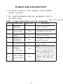
1
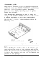
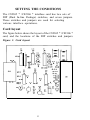
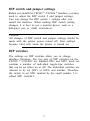
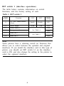
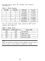
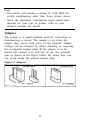
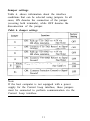
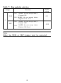
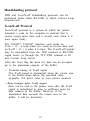
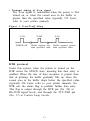
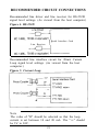
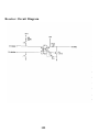
EPSON
Serial Interface
Card
C82305*
C8230*
English
Deutsch
Français
ESpañol
Italiano
4000152
C01-00
NOTICE
All rights reserved. Reproduction of any part of this manual in any form whatsoever
without Seiko Epson’s express written permission is forbidden.
The contents of this manual are subject to change without notice.
All efforts have been made to ensure the accuracy of this manual. However, should any
errorS be detected. Seiko Epson would greatly appreciate being informed of them
The above notwithstanding. Seiko Epson can assume no responsibility for any errors
in this manual or their consequences.
Copyright © 1990 by- Seiko Epson Corporation. Nagano, Japan
Serial Interface
C82305 * /C82306 *
English
Schnittstellenkarte
C82305 * /C82306 *
Deutsch
Interface série
C82305 * /C82306*
Français
Interface en serie
C82305 * /C82306*
Español
Interfaccia seriale
C82305* /C82306*
Italiano
TABLE OF CONTENTS
INTRODUCTION
About this guide
2
3
SETTING THE CONDITIONS
Card layout
DIP switch and jumper settings
DIP switches
Jumpers
4
4
5
5
10
DATA ENTRY
Serial communication
About data entry
Handshaking protocol
13
13
13
14
SPECIFICATIONS
17
HARDWARE DESCRIPTION
19
RECOMMENDED CIRCUIT CONNECTIONS
21
INSTALLATION
22
INTRODUCTION
The Serial Interface Card 032305 * /C82306 * is an interface
that allows asynchronous serial data communication
between a host computer and an EPSON printer.
This interface card offers the following features:
• Data transmission that can be set at either RS-232D
or 20 mA Current Loop levels (RS-232D has been
revised from the former RS-232C. Set the signal
levels for RS-232D the same as for RS-232C.)
• Handshaking protocol using X-on/X-off or DTR flag
control
• Selectable data word structure that allows you to
choose parity (Odd, Even, or None) and word bit
settings (either 7 or 8 bit)
• Selection of baud rate settings from 75 to 19,200 BPS
(Data transmission speed is limited to 1,200 BPS
when the signal level is set to 20 mA Current Loop)
l
DIP switch 1 settings that you can change even after
installation
About this guide
This guide is designed to give you detailed information
on how to install your C82305 * /C82306 * serial interface
card in a variety of EPSON printers. Installation
procedures vary slightly depending upon the printer
model that you have.
Also included are instructions on how to adjust the
settings of the C82305 * /C82306 * interface card, as well as
a general description of serial data communication.
The C82305 * /C82306 * option package contains the
following items:
C82305*
C82306* serial I/F card (1)
Optional connector lock nuts (2)
Note
When attaching the interface cable to the interface, you
may find that the screws of your interface cable do not
fit into the connector lock nuts. If this happens you will need
to replace the connector lock nuts with the optional ones
provided in this package.
3
SETTING THE CONDITIONS
The C82305 * /C82306 * interface card has two sets of
DIP (Dual In-line Package) switches, and seven jumpers.
These switches and jumpers are used for selecting
various interface operations.
Card layout
The figure below shows the layout of the C82305 * /C82306 *
card, and the locations of the DIP switches and jumpers.
Figure 1. Card layout
4
DIP switch and jumper settings
Before you install the C82305 * /C82306 * interface, you may
need to adjust the DIP switch 2 and jumper settings.
You can change the DIP switch 1 settings after you
install the interface. When making DIP switch setting
changes, it is best to use a pointed device, such as a
ball-point pen or small screwdriver.
Caution
All changes of DIP switch and jumper settings should be
made with the printer power turned off. New settings
become valid only when the printer is turned on.
DIP switches
The settings on DIP switches allow you to change
interface functions. The two sets of DIP switches on the
C82305 * /C82306* are labelled SW1 and SW2. Each set
contains a number of individual toggle-type switches
that can be set either on or off. The individual switches are
referred to by set (SW1 or SW2) and number. Therefore,
the switch in set SW1 marked by the small number 3 is
called DIP switchl-3.
5
DIP switch 1 (interface operations)
The table below contains information on switch
functions, and the factory setting of each.
Table 1. DIP switch 1
Switch
number
1-1
Function
ON
I/F card enable/disable
(Note)
l-2
Word length
l-3
1-4
Parity check 1
Parity check 2
l-5
Baud rate 1
l-6
Baud rate 2
Enable
OFF
Factory
setting
Disable
ON
I
8 bit
7 bit
ON
OFF
See Table 4.
OFF
ON
See Table 5.
OFF
Note
Some printers have a selecting switch (or function) that
allows you to select between the optional and original
interfaces. If you install the interface card in this type of
printer, you should set DIP switch l-l on the interface
card to ON and also change the setting in the printer to
select the optional interface.
6
DIP switch 2 (interface operations)
The table below contains information on switch
functions, and the factory setting of each.
Table 2.
Data word structure
The data word structure is also operator selectable
through DIP switch settings (See Table 1). The word
structure for serial data is:
1 start bit +7 or 8 data bits (selectable) + 1 parity
bit (selectable) +1 or more stop bits.
The table below shows the possible word structure
combinations.
Table 3. Word structure
You can select the parity check method by DIP switch
settings. (See Table 4.)
Table 4. Parity check
Note
Since the selection of parity check depends on your type of
printer, refer to your printer’s manual for details.
Baud rate selection
In serial data communication, data is transmitted in the
form of bits. These data bits go out one at a time along
a single path, and in a specified order. The BPS (Bits
Per Second) rate, or speed at which these bits are
transmitted, can be selected using a combination of DIP
switch settings.
Note
In the current loop mode, accurate data transfer cannot be
guaranteed at a baud rate setting exceeding 1,200 BPS.
Table 5. Baud rate selection
Note
• The printer will assume a setting of 1,200 BPS for
switch combinations other than those shown above.
• Since the maximum transmission speed (baud rate)
depends on your type of printer, refer to your
printer’s manual for details.
Jumpers
The jumper is a small terminal used for connecting or
disconnecting a circuit. The jumper is on when the
jumper plug covers both wires of the terminal. Jumper
settings can be changed by either attaching or removing
the rectangular jumper plug. If the jumper is to be
turned off, connect it to just one of the two terminal
pins as shown in the figure below. By doing this, you
can avoid losing the unused jumper plug.
Figure 2. Jumpers
10
Jumper settings
Table 6. shows information about the interface
conditions that can be selected using jumpers. In all
cases, ON denotes the connection of the jumper
(covering both terminals), while OFF denotes the
disconnection of the jumper.
Table 6. Jumper settings
Note
If the host computer is not equipped with a power
supply for the Current Loop interface, these jumpers
must be connected to perform communication via the
Current Loop interface.
11
Table 7. Flag polarity selection
Jumper
Function
ON:
JNOR
MARK (do not accept data) =
Current ON
Factory
setting
ON
ON: MARK (do not accept data)=
Negative EIA level
J5
ON:
MARK (do not accept data) =
Current OFF
ON:
MARK (do not accept data)=
Positive EIA level
JREV
OFF
Note
Either the JNOR or JREV jumper must be connected.
12
DATA ENTRY
This section gives a brief description of serial data
communication conditions and handshaking protocols
supported by the C82305 * /C82306 * interface card.
Serial data communications
The CL32305 * /C82306 * interface allows you to select
either RS-232D or 20 mA Current Loop signal levels;
but never both at the same time.
This interface card also provides for either DTR (Data
Terminal Ready) or X-on/X-off handshaking protocol.
About data entry
Transmitted data from a host computer is stored in your
printer’s internal buffer. (This interface card has no
buffer memory.) When this buffer becomes full, any
additional transmitted data cannot be accepted and
would be discarded. To prevent such data loss, special
handshaking protocols are provided to regulate the flow
of data transmission. The two protocols available on the
C82305 * /C82306 * interface card are DTR and X-on/X-off.
Note
When a parity error (if parity check is enabled), framing
error, or overrun error is detected in the data received,
data is ignored or an asterisk (*) is printed instead.
(Since the handling of communication errors depend on
your type of printer, refer to your printer’s
specifications for details.)
13
Handshaking protocol
DTR and X-on/X-off handshaking protocols can be
performed under either RS-232D or 20mA Current Loop
transmission.
X-on/X-off Protocol
X-on/X-off protocol is a system in which the printer
transmits a code to the computer to indicate that it
cannot accept more data, and a second code when it is
once again ready.
The C82305* /C82306* interface card sends an
X-on < 11 > H code when it is ready to receive data, and
an X-off < 13 > H when it is busy. The X-on/X-off signals
may be transmitted from the TXD terminal at RS-232D
signal levels, or through the TTY-TXD terminal at 20
mA Current Loop levels.
After the X-on flag has been set, data can be accepted
up to the maximum capacity of the buffer.
•
Transmit timing of X-off signal
The X-off signal is transmitted when the vacant area
in the buffer drops below the specified value
(typically 256 bytes; refer to your printer manual).
• Data transfer after X-off signal
Data can be sent to the printer even after the X-off
signal is transmitted as long as sufficient room for
data remains in the buffer. However, if the
transmitted data exceeds the vacant area in the
buffer, it will be discarded.
14
• Transmit timing of X-on signal
The X-on signal is transmitted when the power is first
turned on, or when the vacant area in the buffer is
greater than the specified value (typically 512 bytes;
refer to your printer manual).
Figure 3. X-on/X-off thing
X-ON
POWER ON
X-OFF
X-ON
Buffer capacity less
than specified value
Buffer capacity greater
than specified value
DTR protocol
Under this system, when the printer is turned on the
DTR enters the SPACE state, meaning that data entry is
enabled. When the rate of data reception is greater than
that of printing, the buffer gradually fills up. Once the
vacant area in the buffer drops below the specified value
(typically 256 bytes; refer to your printer manual), the
DTR sets the status flag to prohibit further data entry.
This flag is output through the DTR pin (No. 20) at
RS-232D signal levels, and through the TTY-TXD pin
(No. 17) at Current Loop Levels.
15
With the status flag set, and data reception prohibited,
the vacant area of the buffer gradually increases as the
printer continues to print. When the vacant area in the
buffer reaches the specified value (typically 512 bytes;
refer to your printer manual), the flag is reset and data
entry is again enabled.
Note
Reverse Channel pin (No. 11) and DTR pin (No. 20) are
internally connected on the interface board and must
have identical signal levels.
Printer status error
The flag will be set immediately regardless of the
remaining buffer capacity if the printer detects an error.
16
SPECIFICATIONS
1. Synchronization: Asynchronous
2. Baud Rate: 75, 110, 134.5, 150, 200, 300, 600,
1,200, 1,800, 2,400, 4,800, 9,600, or
19,200 BPS (selectable)
3. Word length:
Start bit: 1 bit
Data bit: 7 or 8 bits (selectable)
Parity bit: Odd, even, none, or ignore (selectable)
Stop bit: 1 bit or more
4. Input signal polarity:
1) With RS-232D:
MARK = logic "1' ( - 3 to -25V)
SPACE = logic "0" ( +3 to +25V)
2) Current loop:
MARK = logic "1" (Current ON)
SPACE = logic "0" (Current OFF)
Note
The above voltage, between pin No. 17 and No. 24,
must not exceed 25V.
17
5. Handshaking
Table 8. Handshaking
US-232D
Control Loop
Using DTR protocol
The two signal
The impedance
conditions at pm No. between pin No. 17
11 and pin No. 20 are and pin No. 24 is as
as follows;
follows;
MARK-data entry is LOW(MARK)-data
disabled
entry is disabled
SPACE-data entry is High(SPACE)-data
enabled
entry is enabled
Using X-ON/X-OFF
protocol
Data transmitted from
pin No. 2 is controller
as follows;
X-ON<ll>H-data
entry is enabled
X-0FF<13>H-data
entry is disabled
Data transmitted by
the change of the
impedance between
pin No. 17 and pin
No. 24 is controlled a s
follows;
X-ON<ll>H-data
entry is enabled
X-OFF<13>H-data
entry is disabled
The DTR signal is always set to SPACE while X-on/
X-off handshaking is selected.
X-on/X-off characters will not be transmitted from TXD
while DTR handshaking is selected (TXD signal is
always set to MARK).
Note
Operation is not guaranteed when using the current loop
mode at rates over 1,200 BPS.
18
HARDWARE DESCRIPTION
1. I/F board connector: EIA standard 25-pin D-SUB
female connector.
2. For signal description and pin assignment, refer to
the table below:
Table 9. Signal Description and Pin Assignment
Pin No.
Signal name
1
protective
Ground
2
Transmitted
Data (TXD)
3
Received Data
(RXD)
4
I
Request to
Send (RTS)
Direction
—
Text
Ill
out
I
Signal Ground
In
11
Reverse
Channel
(=2nd RTS)
Out
20
Data Terminalk t
Ready (DIR)
Out
7
19
signal is at he positive
Description
Chasis ground
Transmitted serial data
Received serial data
This signal is always at the
positive EIA level.
Return path for data and
control signals.
This
EIA Level when the printer is
ready to accept data entry
and at the negative EIA
level when the printer is not
ready to accept data entry
Operator can invert the
polarity of the signal with
jumper 15.
Pin No.
Signal Name
Direction*
17
TTY-TXD
out
24
TTFTXD
Return
—
25
23
TTY_RXD
T
e
Return
x
t
In
Description
High impedance (‘SPACE’)
between pin No. 17 and No
24 or an X-on signal sent
across pin No. 17 and No.
24 indicates that the printer
is ready to accept data. Low
impedance (‘MARK’) or an
X-off signal being sent
indicates that the printer is
busy. Operator can invert
the polarity of this signal
with jumper J5.
Input data of serial Current
Loop.
—
Note
• The column heading “Direction” refers to the direction
of signal flow as viewed from the printer.
• All signals except TTY-TXD and TTY-RXD comply
with the EIA RS-232D standard.
20
RECOMMENDED CIRCUIT CONNECTIONS
Recommended line driver and line receiver for RS-232D
signal level settings. (As viewed from the host computer.)
Figure 4. RS-232D
Serial Interface Card
Line Receiver
Recommended line interface circuit for 20mA Current
Loop signal level settings. (As viewed from the host
computer.)
Figure 5. Current Loop
Note
The value of "R" should be selected so that the loop
current is set between 10 and 20 mA. The "+v" should
be 3V to 24V.
21
INSTALLATION
The C82305* /C82306* interface card is designed to be
installed inside the printer. Installation or removal of the
interface board is easy, and requires only a screwdriver.
The following section gives you detailed information on
how to install your interface card in a variety of
EPSON printers.
Caution
• Turn off the power to the printer and the computer
before installing the serial interface. Make sure that all
power and interface cables are removed.
• Avoid touching the printer’s circuit board contacts, as
many of these components are sensitive to static
electric charges that may build up on your body.
1. First, you may need to adjust the DIP switches and
jumper settings.
If the screws don’t fit your interface cable, you will
need to replace the connector lock nuts with the
optional ones provided in this package.
Note
The original CS2305* lock nuts are imperial standard
(inch), and the C82306* lock nuts are metric.
22
2. Fit both sides of this interface card into the guides
inside the compartment.
3. Insert this interface card until the interface pins mate
with the connector inside your printer.
4. Secure the interface with the two screws.
23
Current-Loop Transmitter/Receiver
Circuit Diagrams
Set the Jumper Jl, J2, J3, and J4 referring to the
following diagrams.
Transmitter Circuit Diagram
121
Receiver Circuit Diagram
122
l
EPSON OVERSEAS MARKETING LOCATIONS
EPSON AMERICA. INC.
2780 Lomita Blvd.
Torrance. Cailif. 90505. U S A
Phone (213) 539-9140
Fax (213) 534-5854
EPSON DEUTSCHLAND GmbH
Zülpicher StraBe 6,4000 Düsseldorf 11
F.R. Germany
Phone: (0211) 56030
Telex: 6584786
EPSON UK LTD.
campus 100. Maylands Avenue.
Hemel, Hempstead. Herts.
HP2 7EZ, UK
Phone: 442-61144
Telex: 5182467
EPSON FRANCE S. A.
68 bis. rue Marjolin 92300
Levallois-Perret, France
Phone: (1) 47-373333
Telex: 610657
EPSON AUSTRALIA PTY. LTD.
Unit 3, 17 Rodborough Road.
Frenchs Forest NSW 2086 Australia
Phone: (2) 452-0666
Fax (2) 975-1409
EPSON SINGAPORE PTE. LTD.
No. 1 Raffles Place #26-00
OUB Centre. singapore 0104
Phone: 5330477
Fax: 5338119
EPSON HONG KONG LTD.
25/F, Harbour Centre.
25 Harbour, Road Wanchal
Hong Kong
Phone: 8314600
Telex: 65542
EPSON ELECTRONICS TRADING LTD.
(TAIWAN BRANCH)
1OF, No, 287 Nanking E. Road Sec. 3,
Taipei. Taiwan R. O. C.
Phone: (02) 717-1360
Fax: (02) 712-9164
EPSON ITALIA S.p.A.
V, le F. IIi Casiraghi. 427 20099
SESTO S, GIOVANNI MI. Italy
Phone: 2-262331
Fax: 2-2440750
EPSON IBERICA. S.A.
paris. 152, 08036 Barcelona. Spain
Phone: 410-34-00
Fax: 439-95-17
SEIKO EPSON CORPORATION
(Hirooka Office)
80 Harashinden. Hirooka
Shiojiri-Shi, Nagano-Ken
399-07 Japan
Phone: (0263) 52-2552
1990 May
Printed in Japan 90.07-.2