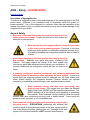
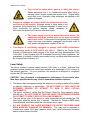
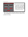
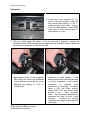
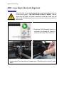
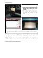
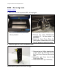
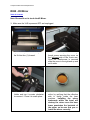
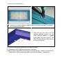
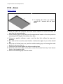
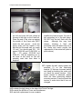
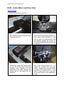
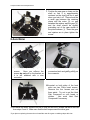
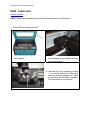
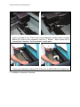
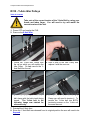
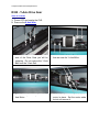
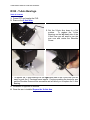
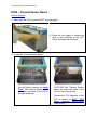
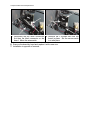
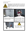
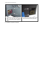
1
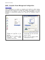
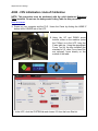
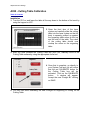
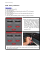
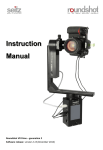
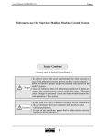
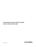
GO TO
Table of Contents
PRELIMINARY
03-13-2008
16008 North 81st Street • Scottsdale, Arizona 85260 • 480.483.1214 • www.ulsinc.com
Table of Contents
Help
0000 - Contact the ULS Technical Support Department
0010 - Performing Professional Series Service Procedures
Adjustments and Settings
A000 - Safety
A005 - Computer Power Management Configuration
A010 - Laser Power Upgrading
A020 - CPU Initialization / Auto-Z and Rotary Calibration
A030 - Cutting Table Calibration
A040 - Rotary Calibration
A050 - X-axis Arm Alignment Check and Adjustment (Squaring)
A060 - Laser Beam Alignment
A070 - Z-axis Leveling
Component Removal and Replacement
Optics
R000 - Focusing Lens
R010 - Mirror 3
R020 - Mirror 2
R030 - Beam Window
Enclosure and Laser
R100 - Rear Cover
R110 - Top Door/Window
R120 - Exhaust Plenum
R130 - Rulers
X-Axis
R200 - X-Axis Bearings
R210 - X-Axis Belt
R220 - X-Axis Idler Pulley
R230 - X-Axis Motor and Drive Gear
R240 - X-Axis Arm
Y-Axis
R300 - Y-Axis Belts
R310 - Y-Axis Idler Pulleys
R320 - Y-Axis Drive Gears
R330 - Y-Axis Bearings
R340 - Y-Axis Motor
Z-Axis
R400 - Z-Axis Motor
R410 - Z-Axis Board Replacement
Electronics
R500 - Laser
R510 - CPU
R520 - Keypad
R530 - Upper Flex Board
R540 - Lower Flex Board
R550 - Thermal Sensor Board
R560 - Thermal Snap Switch
R570 - Power Supply(s)
Photos
P0010 - Front View
P0020 - Rear View, Laser Tube Installed
P0030 - Rear View, Laser Tube Removed
P0040 - Left and Right Side Views, PLS3.60, 4.60, 6.60
P0050 - Left and Right Side Views, PLS6.120D
Help
0000 – ULS Technical Support Department
Table of Contents
Technical Support Department
16008 North 81st Street
Scottsdale, AZ 85260
Phone: 480-609-0297
Fax: 480-609-1203
Hours: M – F 8 am to 5 pm
Web: http://www.ulsinc.com
Email: [email protected]
Help
0010 – Performing
Service Procedures
Table of Contents
Safety
When performing the procedures in this manual, always be sure to read and understand
the entire procedure before beginning to operate the machine. Follow each step
carefully. Pay special attention to steps requiring the PLS to be unplugged!
Do not attempt to perform any of the procedures outlined in this
manual until you have read and thoroughly understand section
A000 – Safety.
Difficulty
The PLS is a very easy machine to maintain and repair. Most service procedures are
simple to perform and require minimal time and tools. In order to provide some
indication as to the difficulty or involvement of the service procedures in this manual, we
have employed the following system:
Procedure requiring very little time and skill
Procedure requiring a moderate amount of time or skill
A more involved procedure requiring a greater amount of time or skill
Tools
Nearly all the procedures described in this manual can be performed with a minimum of
simple hand tools:
Hex Key Set, Standard (SAE) including sizes:
9/64, 1/8, 7/64, 3/32, 5/64, 1/16, .050
Screwdrivers, including Phillips #1, #0
Lens Cleaning Solution, Cotton Swabs or Lens Tissue
Needle Nose Pliers
Adjustments and Settings
A000 – Safety – PLEASE READ!
Table of Contents
Description of Appropriate Use
This device is designed for laser cutting and engraving of the materials listed in the PLS
printer driver. Materials to be processed must fit completely inside the system for
proper operation. Use of the equipment in a manner other than that described in this
manual may result in injury to yourself and others and may cause severe damage to the
equipment and your facility.
General Safety
•
Exposure to the laser beam may cause physical burns and can
cause severe eye damage. Proper use and care of this system are
essential to safe operation.
•
Never operate the laser system without constant supervision
of the cutting and engraving process. Exposure to the laser
beam may cause ignition of combustible materials and start a fire.
A properly maintained fire extinguisher should be kept on hand at
all times.
•
Never leave materials in the laser system after laser processing
has finished. Materials may ignite after laser processing has
finished. Thoroughly inspect the interior of the laser system and
remove any particulate materials before leaving your workstation. A
properly maintained fire extinguisher should be kept on hand at all
times.
•
A properly configured, installed, maintained, and operating particulate/fume
exhaust system is mandatory when operating the laser system. Fumes and
smoke from the engraving process must be extracted from the laser system and
either filtered through the Integrated Exhaust Filtration Module (an optional
accessory) or exhausted outside through a user supplied exhaust system.
•
Some materials, during and after laser processing, may
produce toxic fumes. We suggest that you obtain the Material
Safety Data Sheet (MSDS) from the materials manufacturer. The
MSDS discloses all of the hazards when handling or processing
that material. Some materials continue emitting fumes for several
minutes after laser processing and may pose a health hazard. Avoid using this
device in small, enclosed, or non-ventilated areas.
•
Some materials, during and after laser processing, may produce
corrosive fumes. DISCONTINUE processing any material that
produces signs of chemical deterioration in the laser system such as
rust, metal etching or pitting, peeling paint, etc. Damage to the laser
system from corrosive materials is NOT covered under warranty.
Adjustments and Settings
•
•
Dangerous voltages are present within the electronics and laser
enclosures of this system. Although access to these areas is not
necessary during normal use, if it becomes necessary to open one of
these enclosures for service reasons, please remember to
disconnect the power cord from your electrical supply.
•
•
Care should be taken when moving or lifting this device.
Obtain assistance from 3 or 4 additional people when lifting or
carrying (secure motion system and access door). Severe bodily
injury may occur if improper lifting techniques are applied or the
system is dropped.
The power supply cord is the mains disconnect device; the
equipment should be located close to an easily accessible
wall socket outlet. To disconnect the equipment from the supply
mains, the power cord shall be unplugged from the wall outlet or
main power inlet (appliance coupler) of the unit.
This device is specifically designed to comply with CDRH performance
requirements under 21 CFR 1040.10 and 1040.11. CDRH is the Center for the
Devices of Radiological Health division of the Food and Drug Administration (FDA)
in the USA. It also complies with CE (European Community) safety regulations. No
guarantees of suitability or safety are provided for any use other than those specified
by Universal Laser Systems, Inc.
Laser Safety
The device contains a sealed carbon dioxide (CO2) laser in a Class I enclosure that
produces intense invisible and visible laser radiation at a wavelength of 10.6 microns in
the infrared spectrum. For your protection, this enclosure is designed to completely
contain the CO2 laser beam.
CAUTION – Use of controls or adjustments or performance of procedures other
than those specified herein may result in hazardous radiation exposure.
•
•
•
•
The intense light that appears during the engraving or cutting process is the product
of material combustion or vaporization. DO NOT STARE AT THIS LIGHT FOR
EXTENDED PERIODS OR ATTEMPT TO VIEW IT WITH OPTICAL
INSTRUMENTS.
This device contains a visible Red Dot Pointer (Class IIIa, 5mw maximum output,
630-680 nm). DO NOT STARE AT THIS RED LIGHT FOR EXTENDED PERIODS
OR ATTEMPT TO VIEW IT WITH OPTICAL INSTRUMENTS.
The user access door of this device is safety interlocked and will disable the CO2
laser beam when the access door is opened. The Red Dot Pointer is NOT safety
interlocked and is activated when the user access door is open.
DO NOT OPERATE THE LASER SYSTEM IF ITS SAFETY FEATURES HAVE
BEEN MODIFIED, DISABLED OR REMOVED. This may lead to exposure to
invisible and visible CO2 laser radiation which may cause permanent blindness
and/or severe burns to the skin.
Adjustments and Settings
A005 - Computer Power Management Configuration
Table of Contents
Power management is an option on computers and monitors to reduce energy
consumption when they are not in active use. However, your computer is a critical
component in the operation of the PLS. Active Power Management can cause
interruption of communication between the PC and the PLS, resulting in failure of
operation.
1. With your computer fully booted into
Windows XP, right-click on your
desktop.
2. From the list of options, select
“Properties”.
The
“Display
Properties” box will open.
3. In Display Properties, select the
Screen Saver tab. Set the Screen
saver to “(None)”.
4. Then in the box “Monitor power”,
Click the button “Power…”
Adjustments and Settings
5. Select the tab “Power Schemes”.
6. For the “Settings for Home/Office
Desk power scheme” box, select
“Never” for all the setting options:
Turn off monitor, Turn off hard
disks, System standby, and System
hibernates.
7. Click “Apply”, then “OK” on both
open windows.
8. The configuration is complete.
Adjustments and Settings
A010 – Laser Power Upgrading
Table of Contents
The PLS3.60, PLS4.60, and PLS6.60 is capable of upgrading to a maximum of 60
watts. The PLS6.120D is capable of upgrading to a maximum of 120 watts (two 60 watt
laser tubes).
If you are upgrading either system, the PLS’s internal software (firmware) will
automatically reflect the change. Nothing has to be done to the laser system to have it
function properly.
Adjustments and Settings
A020 - CPU Initialization / Auto-Z Calibration
NOTE: This procedure must be performed with the solid aluminum Engraving
Table installed. Do not use the honeycomb Cutting Table for this procedure.
Table of Contents
1. Power up your computer and the PLS. Home the Z-axis by clicking the HOME Z
button in the VIEWER tab of the VCP.
2. Using the UP and DOWN arrow
buttons, either on the machine (enter
the Z Menu) or in the UCP, bring the
Z-axis table up. Using the appropriate
Focus Tool for the lens installed (the
standard is 2.0, other Focus Lens Kits
are optional), focus directly on the
surface of the table.
3. In the UCP, click the SYSTEM tab and choose 2.0 from the Lens Size list.
Adjustments and Settings
4. Click on the Calibrate button within the Lens Size box of the System Tab. The
following window appears. Click on Save to accept the new Z Position. Your 2.0
Lens has now been calibrated.
5. If you have purchased any other optional lens kits, calibrate the lens kit according
to steps 1 through 4. Be sure you select the proper lens size from the list before
calibrating.
6. You are now done calibrating your Lens Sizes and the Auto Z feature with the
standard engraving table.
Adjustments and Settings
A030 - Cutting Table Calibration
Table of Contents
Installation
1. Turn the PLS on and lower the table all the way down to the bottom of its travel by
using the keypad or UCP.
1
2
3
4
5
6
7
8
9
10
11
12
13
14
15
16
17
18
19
1
2
3
4
5
6
7
8
9
10
11
12
13
14
15
16
3
5
6
7
8
9
10
11
12
21
22
23
24
ADJUSTABLE MANIFOLD
1
2
4
20
1
2
3
4
5
6
7
8
9
10
11
12
ENGRAVING TABLE
CUTTING TABLE
17
18
19
20
21
22
23
24
2. Open the front door of the laser
system and carefully slide the cutting
table into the laser system so that its
body is squarely pushed up against
the engraving table rulers on the top
and the side of the table. The rulers
of the cutting table should now
overlap the rulers on the engraving
table.
3. After you have installed the Cutting Table into your PLS, manually focus to the
Cutting Table surface by using the appropriate focus tool.
4. Once that is complete, go directly to
your System Tab and you will notice
that the red CALIBRATE button for
the Cutting Table box will be
activated. Click on the CALIBRATE
button.
A window will appear.
Accept the new Z-height BY clicking
on SAVE.
5. You are now done calibrating the new Z-height for engraving or cutting on the
Cutting Table.
Adjustments and Settings
A040 - Rotary Calibration
Table of Contents
1.
2.
3.
4.
5.
6.
7.
Turn on the UCP and PLS.
Open the top door.
Lower the table about half way down by using the UCP or the keypad.
Turn off the PLS.
Properly mount the Rotary on top of the engraving table and plug it in.
Turn on the PLS.
The rotary will automatically rotate to indicate it’s properly connected.
8. Select the System Tab on the UCP
and click on the CALIBRATE button in
the Rotary box. After the button has
been clicked a Rotary Calibration
window will appear with Y Position
and Z Position boxes. Now, in the Y
Position box use the Y Axis buttons
(1) to move the focus carriage back
and forth. Place the focus carriage
exactly at 2.625”.
9. Next, use the X Axis buttons (2) to move the focus carriage left and right and place
the red LED over the flat part of the concave metal fixture normally located on the
left hand side on the rotary.
Adjustments and Settings
10. Now, use the Z Axis buttons (3) or the
Z Axis Menu on your keypad
(recommended) to move the table up
and down and use the Focus Tool
method to focus on top of the flat part
of the concave metal fixture with the
focus tool. DO NOT focus on top of
the black metal cover that is located
on the left hand side of the rotary.
11. After focusing is complete click both SAVE buttons on the Rotary Calibration
window. If asked to overwrite existing positions accept the new values by clicking on
YES. Once complete click the CLOSE button and the focus carriage will re-home
once you exit the window.
12. Calibration is now complete.
Adjustments and Settings
A050 - X-axis Arm Alignment Check and Adjust (Squaring)
Table of Contents
1. Power off the PLS and unplug it.
2. Remove the #2 mirror cover (1) by
removing the thumbscrew (2), sliding
the cover to the right and then off the
rail.
3. Grasp the X-axis arm and slowly pull the arm towards you until it stops.
4. Observe if the left side and right side of the X-axis arm makes contact with the left
and right side shoulder screws, at the same time, respectively.
5. If there is a gap between the shoulder screw and the contact point on either the left
or right side of the arm, you will need to square the arm by making an adjustment.
Adjustments and Settings
Adjustment
6. Locate the Y-axis couplers (1). For
each of the two couplers, there are
two screws that mount it to the Ymotor and the Y-axis shaft. Using a
3/32 inch Allen wrench, choose ONE
(only one) of those four screws (2)
and loosen it a ½ turn.
7. With your hand, grasp the center of the arm and pull it forward to contact the
shoulder screws. While holding the arm against the two shoulder screws, tighten the
screw that you loosened in the previous step.
8. Now, push the arm into the
approximate center of the engraving
field. With your thumb and forefinger
of your left hand, touch the two y-axis
bearings and attempt to “turn” or
“rotate” them.
10. Re-install the #2 mirror cover.
11. Squaring is complete.
9. You should feel an equal turning
resistance for each bearing. If one
bearing spins freely and the other has
a turning resistance, or the turning
resistance
is
unequal,
then
adjustment is necessary. To adjust,
using a 3/32 inch Allen wrench,
loosen BOTH the two socket head
screws ¼ turn.
Then, re-tighten
them. This procedure automatically
equalizes the force on both Y-axis
bearings.
Re-check the turning
resistance once again and re-adjust if
necessary.
Adjustments and Settings
A060 - Laser Beam Check and Alignment
Table of Contents
Verify the table is clear of any objects that could obstruct the movement
of the motion system. THE RED DIODE IS ONLY A GUIDE. The red
diode may be slightly off center compared to the burn mark you will
make in the following steps so we recommend you make a burn mark for
best results.
1. Power the PLS ON and let it home, or
re-home it by clicking the Home XY
button in the Viewer Tab of the UCP.
2. Remove the optics from the Focus Lens Carriage by unscrewing all 3 thumb
screws and pull the face plate out towards you. Place the optics in a safe, clean
place.
Adjustments and Settings
3. Place a strip of masking tape over the
hole on the left side of the Focus
Carriage.
4. The red diode beam should appear
on the tape. The red diode beam
should be fairly centered over the
hole.
5. Using the Focus Feature (1) of the Viewer Tab in the UCP, verify the position of
the red diode beam relative to the hole in the focus carriage in all four corners of
the table.
6. The red diode should be fairly centered on the hole in all four corners of the table. If
this is the case, you can remove the masking tape from the hole in the focus
carriage and reinstall the optics. The red diode is aligned.
7. If the red diode beam is not centered on the hole in all four corners of the table, the
beam will need to be aligned. Do not remove the masking tape or reinstall the optics.
8. Power off the PLS and unplug the unit.
Adjustments and Settings
9. Slowly move the X-axis arm (1)
forward.
10. Locate and carefully remove the large
thumb screw securing the cover on
the left-hand side of the X-axis arm.
Remove this cover.
11. Plug in the PLS and turn the power on with the top door open.
12. Once it finishes homing proceed to the System Tab then click on the Alignment
Launch button. The Alignment Mode window will appear.
13. Click on the upper left hand Move
button. The PLS’s focus carriage will
move to the indicated X, Y position.
14. With the cover removed, locate the three adjusting screws on the #2 Mirror mount
on the left-hand side of the X-axis arm. Turn these screws to center the red dot
diode.
Adjustments and Settings
Note: To create a small burn mark on the tape in the next step you will need to adjust
your Power and Seconds settings in the Alignment Mode screen (lower left side).
Lower power laser tubes require higher power settings and higher power laser tubes
require lower power settings to make the burn mark on the tape.
15. Once the red diode is centered adjust
the Power and Seconds settings on
the lower left side of the Alignment
Mode window.
Start of with 5%
Power and 2 Seconds.
16. Close the top door if it’s not already
closed and then click on the Activate
Laser button.
• If a burn mark is not made
continue to modify the Power and
Seconds settings.
17. If the burn mark is not centered use a new piece of tape and adjust the
corresponding screw in small turns on the #2 Mirror mount until the burn mark is
centered.
• Keep in mind that you can use the red diode as a guide.
18. If the burn mark is centered continue to the next step.
19. Once the burn mark is centered keep the piece of tape on the focus carriage.
20. Now click on the lower right side
Move button.
21. Close the top door if it’s not already
closed and then click on the Activate
Laser button. Take note of the burn
mark.
22. Both burn marks should be over lapping each other. If they are not continue to
adjust the #2 Mirror for the lower right hand corner.
23. Once aligned Exit the Alignment Mode Window and remove the masking tape from
the Focus Lens Carriage and reinstall the optics.
24. Power off and unplug the PLS.
25. Reinstall the cover and two screws over the #2 mirror mount from step 10.
Component Removal and Replacement
R000 – Focusing Lens
Table of Contents
1. Make sure the PLS is powered OFF and unplugged.
2. Open the top door and pull the X-Axis
Arm (1) forward.
3. Locate the Focus Carriage (1).
4. Remove the three thumbscrews
completely (2). Set them aside in a
safe place.
5. Grasp the Front Cover Plate (3).
Gently slide it forward and out of the
Focus Carriage to remove the optics.
6. Place the optics on a soft, non-abrasive cloth.
7. Remove the two Phillips head screws
(1) that attach the Focusing Lens to
the Front Cover Plate and remove the
optic.
8. Attach the new Focus Lens to the
Front Cover Plate.
9. Clean the #3 Mirror (2) if necessary.
10. Reinstall the optics in the Focus Carriage.
Component Removal and Replacement
R010 – #3 Mirror
Table of Contents
1. Make sure the PLS is powered OFF and unplugged.
2. Open the top door and pull the X-Axis
Arm (1) forward.
3. Locate the Focus Carriage (1).
4. Remove the three thumbscrews
completely (2). Set them aside in a
safe place.
5. Grasp the Front Cover Plate (3).
Gently slide it forward and out of the
Focus Carriage to remove the optics.
6. Place the optics on a soft, non-abrasive cloth.
7. Remove the two Phillips head screws
(1) that attach the #3 Mirror to the
Front Cover Plate and remove the
optic.
8. Attach the new #3 Mirror to the Front
Cover Plate.
9. Clean the Focus Lens (2) if
necessary.
10. Reinstall the optics in the Focus Carriage.
Component Removal and Replacement
R020 - #2 Mirror
Table of Contents
Note: Be careful not to touch the #2 Mirror.
1. Make sure the VLS is powered OFF and unplugged.
2. Open the top door and slowly slide
the X-Axis Arm (1) forward.
3. Locate and carefully remove the large
thumb screw securing the cover on
the left-hand side of the X-axis arm.
Once the thumbscrew is removed
slide the cover to the right and up and
set it aside.
4. Grab a hold of the Bezel Mirror
Holder and turn it counter clockwise
to remove it. Place it in a safe place.
5. Replace the #2 Mirror with the new
mirror by verifying that the reflection
side is facing inside the laser
machine. Installing the mirror
backwards within the bezel will
destroy the mirror once the laser
beam penetrates the backside of
the mirror, so be sure that you reinstall the mirror correctly.
Component Removal and Replacement
R100 - Rear Cover
Table of Contents
1. Power off the PLS.
2. Walk around to the back of the laser machine.
3. Open the rear cover by pressing down
on the button part of the latches until
the latches pop up.
4. Fold the rear cover down to a resting position.
Component Removal and Replacement
R110 - Top Door/Window
Table of Contents
Obtain assistance from 1 or 2 additional people when removing
the top door.
1. Make sure the PLS is powered OFF and unplugged.
2. Open the top door and locate the 2
hydraulic pressure cylinders. Place
a flat head screw driver between the
slots and push inward to unlock the
cylinders. Do not remove the end
caps.
3. Next, place the flat head screw driver
against the frame of the top door and
the hydraulic pressure cylinder and
push inwards.
The hydraulic
pressure cylinders will come off.
4. Have another person hold the top door and unscrew the 4 screws that hold the top
door in place. Place the screws and washers in a safe place.
5. Place the PLS’s top door on a soft flat sturdy surface like a table with a cloth.
Component Removal and Replacement
6. Locate the 12 window nuts and remove them with needle nose pliers like shown.
Set the window nuts aside.
7. With the top door still on a flat
surface carefully remove all four
Glass Window Mounts by gently
prying them with your fingers. The
Glass Window Mounts may stick on
the top door window.
8. Install the new glass window onto the top door frame.
9. Installation of the Top Door is opposite of removal.
10. Plug in and power ON the PLS. Open and close the door. Check to see if the Red
Diode turns on and off when you open and close the top door, respectively.
Component Removal and Replacement
R130 – Rulers
Table of Contents
1. To replace the rulers you need to
remove all 5 screws and set them
aside.
2. Once the rulers are removed, use some solvent cleaner to remove and debri left
over from the removed rulers.
3. Place masking tape on the table over the approximate location of the ruler positions
extending the full length of the table in box axes.
4. Using your graphic software, create a red line box that outlines the page size
perfectly.
5. Run that cut file to see the exact location of where the edges of your rulers should
be.
6. After the cut file has been run, peel the outside masking layer off leaving the inside
portion to set your rulers to.
7. Gently push the rulers against the leftover masking tape.
8. Once the rulers are in the correct place, reuse the screws from step 1 and secure
them to the engraving table.
9. Remove the masking tape from the inside.
Component Removal and Replacement
R200 - X-axis Bearings
Table of Contents
1. Power OFF and unplug the PLS.
2. Open the top door and bring the XAxis Arm (1) forward.
3. Bring the Focus Carriage to the middle of the X-Axis Arm.
4. Remove the 2 screws located to the
right of the Focus Carriage on the belt
clamp. Be careful not to lose the
washers.
5. If you have Air Assist, unscrew the two screws that hold the Hook Manifold in
place and set the screws aside. Do not pull the Air Assist hoses out of the Air
Assist Track.
Component Removal and Replacement
6. Grab a hold of the Focus Carriage and gently push up then tilt forward to remove
the Focus Carriage from the X-Axis Arm.
7. Hold the Focus Carriage with your
hand or place it on a flat surface and
remove all 3 bearings.
9. Installation is opposite of removal.
8. Take notice of the Bearing Assembly.
There is a small wave washer (2)
between the head of the axle (3) and
the bearing (1). Be careful not lose or
damage this washer. The bearing
itself has no orientation and can be
installed with either surface against
the carriage.
Component Removal and Replacement
R210 - X-axis Belt
Table of Contents
1. Power OFF and unplug the PLS.
2. Remove #2 mirror cover by removing
the thumbscrew and sliding the cover
to the right and up.
3. Remove the two screws (upper and
lower) that attach the Belt Clamp to
the Focus Carriage. Slide the Focus
Carriage off to the left.
4. Loosen the three screws (3) (1/2 turn)
that mount the tensioning bracket (2).
Also, back off the setscrew (1) until
the tip does not make contact (this
will partially release the tension on
the belt) but do not remove the screw
completely.
5. Loosen, do not remove, the 2 screws
that attach to the left of the bracket
that holds the ends of the belt
together. Slide the bracket off of the
end of the belt. DO NOT PULL THE
BELT OUT OF THE X-AXIS RAIL AT
THIS TIME.
JUST LEAVE IT
HANGING. THE PURPOSE IS TO
RELEASE THE BELT TENSION
COMPLETELY.
Component Removal and Replacement
6. Using a stapler, attach one end of the
old belt (2) to one end of the new belt
1). Do not overlap the belt and make
sure that the teeth are in the same
direction.
7. Slowly pull the other end of the old
belt, allowing the new belt to be
pulled through the inside of the X-axis
arm. Make sure that you do not twist
the belt going through the rail. The
teeth of the belt should be facing the
inside.
8. Once the new belt is completely through the X-axis rail, remove the staple and
discard the old belt.
9. Re-attach the belt clamp to the ends of the belt. Make sure that the rounded side
of the clamp faces inwards. Gently pull the belt through the clamp until the slack
in the belt is reduced. Leave the belt slightly loose because we will tension the
belt by adjusting the setscrew on the tensioner bracket on the left side of the Xaxis rail. Now, tighten down the screws on the clamp. DO NOT TRIM OFF THE
EXCESS BELT AT THIS TIME, WE WILL DO THAT LATER.
10. For the next step, you will need a spring scale and a ruler which the end of the ruler
is actually the "0" point. Some rulers "0" point is offset from the end so you would
not want to use that kind of ruler.
Component Removal and Replacement
11. Push the focus carriage all the way to
the left and push the belt clamp all
the way to the right, on the X-axis rail.
Place the end of the ruler up against
the middle of the X-axis arm (NOT
inside the belt groove). Hook the
spring scale onto the middle of the
belt and pull the scale until you reach
1/2 inch. You should read 100 - 125
grams (PLS6.60 and PLS6.120D) or
150 - 175 grams (PLS3.60 and
PLS4.60). We are expecting you to
be loose at this point so you will
probably read less than what is
required.
12. Using scissors trim off the excess belt
material but leave at least 1/4 inch of
belt protruding out of the belt clamp.
DO NOT trim the belt flush with the
clamp.
Although this may look
cleaner, trimming it flush will
eventually cause the belt to slip out of
the clamp and would require the
replacement of the entire belt (refer to
photo above).
13. To tighten the belt, slowly tighten the
setscrew (1) on the tensioning
bracket (2) that was loosened earlier
and keep re-checking the scale until
you have the proper tension. After
proper tension is achieved, tighten
down the three tensioning bracket
mounting screws (3) and re-check the
tension to make sure that it has not
changed.
14. Re-attach the belt clamp to the side of the Focus Carriage.
15. Re-install the #2 Mirror Cover and thumbscrew.
16. X-axis belt replacement is now complete.
Component Removal and Replacement
R220 - X-Axis Idler Pulley
Table of Contents
1. Power OFF and unplug the PLS.
2. Remove #2 mirror cover by removing
the thumbscrew and sliding the cover
to the right and up.
3. Loosen the three screws (3) (1/2 turn)
that mount the tensioning bracket (2).
Also, back off the setscrew (1) until
the tip does not make contact (this
will partially release the tension on
the belt) but do not remove the screw
completely.
4. Once the tension has been released 5. When reinstalling the new Idler Pulley
remove the screws on the Idler Pulley.
insert the pulley in at an angle for
Remove the pulley and replace it with
easier access.
a new one.
6. Retention the X-Axis Belt.
7. Replace the #2 Mirror Cover and screws.
Component Removal and Replacement
R230 - X-Axis Motor and Drive Gear
Table of Contents
1. Power Off and unplug the PLS.
1. Remove #2 mirror cover by removing
the thumbscrew and sliding the cover
to the right and up.
2. Loosen the three screws (3) (1/2 turn)
that mount the tensioning bracket (2).
Also, back off the setscrew (1) until
the tip does not make contact (this
will partially release the tension on
the belt) but do not remove the screw
completely.
2. Once the tension is released from the
X-Axis belt, detach the flexible cable
(1) from the X-axis motor housing by
pressing your fingertip on the
underside of the cable, depress the
locking tab (2), and gently pull the
cable out.
3. Be careful not to make contact with
the Y-axis Home Sensor (3), it is
made out of plastic and can easily
break. Remove the mounting screw
(4) with a 3/32 Allen wrench. It is a
tight fit under there and is very dark
so you may need to use a flashlight to
see it.
Component Removal and Replacement
4. Remove the other mounting screw (5) is on the front side of the motor housing
with a 3/32 Allen wrench. Lift the motor housing off of the arm and put it on a
table in a safe place. Be careful not to drop the Motor Module or touch the Y-axis
home sensor.
5. Before removing the gear, notice its position on the shaft. Working at a separate
table, place the X-axis motor housing upside down. You will now see the drive
gear (1), the retaining clamp (2), and its mounting screw (3). Loosen but do not
remove the mounting screw from the X-Axis motor shaft. Once the screw is loose
lift both the retaining clamp and drive gear and set them aside.
6. If you are replacing the X-Axis Motor continue to step 8, if not continue to the next
step.
Component Removal and Replacement
7. Position the new gear or clamp on the
shaft so that it is approximately
centered on the shaft just like it was
when you took it off. There should be
a small gap between the retaining
clamp and the motor (3), no gap
between the retainer and the gear (2),
and the shaft should be slightly
protruding out of the gear similar to
the picture shown (1). Once the gear
and retainer are in place tighten the
screw.*
X-Axis Motor
8. Loosen the 4 mounting bracket
screws.
Once you remove the
screws do not pull on the bracket as
it is still attached with a wire
connector.
9. Undue the connector by pressing the
connectors latch and gently pulling on
the connector.
10. Located on both sides of the heat
sinks are two Philip head screws.
Remove the four screws and set
them aside. Try not to get the Heat
Sink Compound on your hands or
clothes.
Use more Heat Sink
Compound if necessary.
11. Re-install the Motor Module onto the X-Axis rail with the 2 screws that were removed
from steps 3 and 4. Make sure that the belt loops around the drive gear.
*If you plan on replacing the motor do not install the new drive gear or retaining clap at this time.
Component Removal and Replacement
R240 - X-Axis Arm
Table of Contents
NOTE: Place any hardware removed from the laser machine in a safe place.
1. Power OFF and unplug the PLS.
2. Open the top door. Pull the X-Axis
Arm forward.
3. Remove #2 mirror cover by removing
the thumbscrew and sliding the cover
to the right and up.
4. Unscrew the two protruding screws
(1) on the left side of the X-Axis Arm
near the tensioning bracket (2). Each
screw that is removed has 2 washers.
Set those aside in a safe place.
Component Removal and Replacement
5. Unscrew the two protruding screws on the right side of the X-Axis Arm. One
screw is located in front of the X-Axis motor assembly and the other is located
behind the X-Axis motor assembly near the Y Sensor. Each screw that is
removed has 2 washers. Set those aside in a safe place.
6. Once all four screws are removed grab a hold of the right support bracket, not the
X-Axis motor assembly, and push the X-Axis Arm to the left then tilt it towards you.
7. Installation is opposite of removal.
Component Removal and Replacement
R300 - Y-Axis Belts
Table of Contents
Take note of the current tension of the Y-Axis Belt by using your
thumb and index finger. You will need to try and match the
current tension of the old belt to the new Y-Axis Belt that will be
installed.
1. Power OFF and unplug the PLS.
2. Remove the X-Axis Arm.
3. On both Y-Axis Rails is a Y-Axis Belt
Clamp. Unscrew all 6 screws, 3 on
each, and set the screws and clamp
aside.
4. After the Y-Axis Belt Clamp has been
removed staple the new Y-Axis Belt
(1) to the old belt (2). Do not overlap
the belt and make sure that the teeth
are in the same direction.
5. Slowly pull the other end of the old belt, allowing the new belt to be pulled through
the inside of the Y-Axis Rail. Make sure that you do not twist the belt going through
the rail. The teeth of the belt should be facing inward.
6. Once the new belt is completely through the Y-Axis Rail, remove the staple and
discard the old belt.
Component Removal and Replacement
7. Insert the new Y-Axis Belt ends into
the belt clamp with the belts teeth
facing inward. The Y-Axis belt in
the following image was twisted
for reference only.
8. Once the belt is attached to the belt clamp you will need to tension it. Located on
both ends of the Y-Axis rails are Idler Pulleys (1). To tension the Y-Axis belt turn
BOTH tensioning screws on the Y-Axis rail the same amount.
9. Installation is opposite of removal.
10. Once everything back in place you need to square the X-Axis Arm (X-axis Arm
Alignment Check and Adjust).
Component Removal and Replacement
R310 - Y-Axis Idler Pulleys
Table of Contents
Take note of the current tension of the Y-Axis Belt by using your
thumb and index finger. You will need to try and match the
current tension of the belt.
1. Power OFF and unplug the PLS.
2. Remove the X-Axis Arm.
3. Undue the Y-Axis Belt Clamp from
the rail on which you will replace the
Idler Pulley. Do not remove the YAxis Belt from the rail.
4. Grab a hold of the Idler Pulley and
replace it with the new one.
5. Reinsert the Y-Axis Belt ends into the
belt clamp with the belts teeth facing
inward.
The Y-Axis belt in the
following image was twisted for
reference only.
6. Once the belt is attached to the Belt
Clamp you will need to tension it. To
tension the Y-Axis belt turn BOTH
tensioning screws on the Y-Axis rail
the same amount.
7. Reinstall the X-Axis Arm.
8. Since the Y-Axis Belt was released from its original position the arm will need to be
Squared.
Component Removal and Replacement
R320 - Y-Axis Drive Gear
Table of Contents
1. Power OFF and unplug the PLS.
2. Remove the X-Axis Arm.
3. Remove the Y-Axis Belt Clamp of the
side of the Drive Gear you will be
replacing. Do not remove the Y-Axis
Belt from the Y-Axis Rail.
4. Loosen all the Y-Axis Coupler screws
that are near the Y-Axis Motor.
5. Slide the couplers away from the YAxis Motor.
6. Undue the 4 screws that hold the
motor in place. Set the motor aside
but do not remove it.
Component Removal and Replacement
7. Rotate the long shaft with one hand to
locate the Y-Axis Drive Gear clamp
screw. Loosen but do not remove the
screw.
8. Grab a hold of the drive gear with one hand and pull metal shaft out with the other.
9. Remove the drive gear and replace it with a new one.
10. Reinstall the parts that were removed.
11. Once the machine has been repaired and the Y-Axis Belt has been tensioned you
will need to Square the X-Axis Arm.
COMPONENT REMOVAL AND REPLACEMENT
R330 - Y-Axis Bearings
Table of Contents
1. Power OFF and unplug the PLS.
2. Remove the X-Axis Arm.
3. Set the X-Axis Arm down in a flat
surface.
To replace the Y-Axis
Bearings on the left hand side of the
X-Axis Arm you will need to turn the
arm over and undue the Shoulder
Screw.
4. To replace the Y-Axis Bearings on the right hand side of the X-Axis Arm you will
need to push the Y-Tensioner arms inward. Continue pushing the tensioner arm
and the Shoulder Screw will be accessible and will allow you to replace the Y-Axis
Bearing.
5. Installation is opposite of removal.
6. Once the arm is installed Square the X-Axis Arm.
Component Removal and Replacement
R340 - Y-Axis Motor
Table of Contents
1. Power OFF and unplug the PLS.
2. Open the top door and push the XAxis Arm back.
3. The Y-Axis Motor is located
underneath the frame of the laser
system near the keypad.
4. Undue the electrical connector by
pressing the locking tab and gently
pulling on the connectors.
Component Removal and Replacement
5. Loosen, but do not remove, the coupler screws that attach the motor to the Yshafts. Slide the couplers outwards, away from the motor.
6. Unscrew the 4 screws that hold the
motor to the Y-Motor bracket.
7. Installation is opposite of removal.
8. Once the new motor is installed perform the Square the X-Axis Arm procedure.
Component Removal and Replacement
R400 - Z-Axis Motor
Table of Contents
When performing this procedure, make sure that you do not accidentally
turn the Z-Axis Lead Screws that drive the table up and down; otherwise
you will need to re-level the table later on!
1. Turn ON and lower the engraving table all the way down by either using the keypad
or UCP.
2. Once the engraving table has been lowered power OFF and unplug the PLS.
3. Open the front door.
4. The Z-Axis Motor is located inside of the PLS on the right hand side. Gently pull
on the white and red electrical connector.
Component Removal and Replacement
5. Hold the Z-Axis Motor while
unscrewing the 3 screws that hold the
Z-Axis Motor in place. Set the screws
and washer aside in a safe place.
6. Once the motor is free, tilt the motor
and remove it from the small Z-Axis
Belt.
7. Grab a hold of the Z-Axis Motor with
one hand and with the other hand
loosen the Drive Gears screws.
Remove the Drive Gear and set it
aside.
8. Transfer the Drive Gear from the old motor to the new motor. The Drive Gear
needs to sit flush against the Z-Motors shaft.
9. Transfer the small Z-Axis Belt from the old Z-axis Motor to the new one.
10. Pull the motor to the right to re-apply tension to the belt while tightening the 3
screws.
Component Removal and Replacement
R410 – Z-Axis Board Replacement
Table of Contents
1. If the laser machines table is raised, lower it all the way down by using the UCP or
keypad. Clearance is needed to replace the Z Axis Board.
2. Disconnect power to the laser machine.
3. Unscrew the 2 screws holding the Z
Axis Board in place with an Allen
Wrench. The Z Axis Board is located
inside the right hand side of the
machine.
4. In order to remove the Z Axis Board you will need to gently slide the board from
the laser machines frame. To get access to the wire connectors you will need to
tilt the board.
Component Removal and Replacement
5. Unplug all 3 connectors from the 6. When installing the new board verify
board.
that the 2 white nylon standoffs (pegs)
(only one shown) are placed into the
slotted sheet metal.
7. After the new board has been installed you will need to re-calibrate all the lens you
have, the cutting table (if applicable), and rotary (if applicable) using the UCP’s
System Tab.
Component Removal and Replacement
R500 - Laser
Table of Contents
Handle the laser with care! Do not bump or jar it.
1. Make sure the PLS is powered OFF and unplugged.
2. Press the two hinges to release the
latch on the backside of the PLS.
Gently fold back the rear cover.
4. Rotate the laser, a few degrees, from
the bottom and lift it up and off the
mounts. Store the Laser in a safe
place.
3. Unplug the electrical connector from
the Laser by manually undoing the
two thumb screws and gently pulling
to the left.
5. When reinstalling the Laser Tube
slowly rotate the laser cartridge
making sure that the alignment plate
is centered in the gap of the alignment
fork between the small and large
plates.
Note: The PLS6.60 and 6.120D have two laser tubes. The power connectors are
labeled “Top” and “Bottom”. It is very important that you plug in the correct connector
into the appropriate laser; otherwise the laser system will not function properly.
Component Removal and Replacement
R510 - CPU Driver Board(s) Replacement
Table of Contents
1. Disconnect the power to the laser machine.
NOTE: The Y Motor Drive board is located in the middle. The Z board and the X
board can be interchanged with one another.
2. Located on the back of the laser 3. Gently pull out the assembly. Turn
machine unscrew the 6 screws with
the CPU Assembly over to expose the
an Allen Wrench and set them aside.
driver cards.
Locked
Unlocked
4. To remove the driver board(s), push the metal pin over to unlock the board. If you
facing the fan of the CPU Assembly push the pin to the left.
Component Removal and Replacement
5. Gently pull the driver card straight up
with both hands.
6. When installing the new board verify that the board pins line up. The driver card can
only be properly installed in one direction.
7. Perform the procedure CPU Initialization / Auto-Z and Rotary Calibration.
Component Removal and Replacement
R520 – Keypad
Table of Contents
1. Make sure the PLS is powered OFF and unplugged.
2. Open the top door.
3. Look underneath the front frame of
the PLS.
4. Pop the black metal plate off the 4
metal standoffs by hand.
5. Gently pull on the blue ribbon cable
that’s connected to the keypad
assembly.
Component Removal and Replacement
6. Pop the keypad assembly off from its
6 metal standoffs. DO NOT pull on
the keypad as it is still attached by a
cable.
8. Installation is opposite of removal.
7. Undue the multicolored cable that’s
attached to the end of the keypad
assembly.
Component Removal and Replacement
R530 - Upper Flex Board
Table of Contents
1. Power OFF and unplug the PLS.
2. Remove the X-Axis Motor Module
from the X-Axis Arm.
3. Once the Motor Module has been
removed unscrew the 4 screws that
hold the motor bracket in place.
4. Grab a hold of the motor bracket and
lift it off the X-Axis Motor. Disconnect
the wire connected that is located
underneath the Upper Flex Board.
5. Unscrew the 3 screws that hold the
Upper Flex Board to the motor
bracket and set them aside.
6. Installation is opposite of removal.
Component Removal and Replacement
R540 - Lower Flex Board
Table of Contents
1. Power OFF and unplug the PLS.
2. Open the top door and push the XAxis Arm back.
3. The Upper Flex Board is located on the right hand side near the pressure cylinder.
Unplug the Flex Cable from the Lower Flex Board.
Component Removal and Replacement
4. Unscrew the 2 screws that hold the
board in place.
5. Grab a hold of the Lower Flex Board
and turn it around. Unplug the cable
attached. DO NOT pull on the Lower
Flex Board because it is still attached
to the PLS.
Component Removal and Replacement
R550 – Thermal Sensor Board
Table of Contents
1. Make sure the PLS is powered OFF and unplugged.
2. Press the two hinges to release the
latch on the backside of the PLS.
Gently fold back the rear cover.
3. Locate the Thermal Sensor Board
a. If you have a PLS3.60 or PLS4.60
you will need to remove the Laser
Tube. The Thermal Sensor Board
sits within the frame of the PLS on
the right hand side.
b. If you have a PLS6.60 or
PLS6.120D the Thermal Sensor
Board sits within the frame of the
PLS on the left hand side.
Remove the CPU Assembly of the
PLS as stated on R510 - CPU
Driver Board(s) Replacement
(Step 2 only).
Component Removal and Replacement
4. Disconnect the two white connectors 5. Remove the 3 screws that hold the
first then the black connector on the
board in place. Set the screws aside
board. Move the wires aside.
in a safe place.
6. Remove the board by hand and replace it with a new one.
7. Installation is opposite of removal.
Component Removal and Replacement
R560 – Thermal Snap Switch
Table of Contents
Verify that the battery is reinstalled into the PLS in order for the engraver
to function properly.
Use caution when installing the new Thermal Snap Switch. Do not apply
excessive force when bending the Thermal Snap Switch’s metal
contacts.
1. Make sure the PLS is powered OFF and unplugged.
2. Remove the Thermal Sensor Board’s battery holder by inserting a flat head screw
driver into the slot of the battery holder. Gently push up then pull the screw driver
towards yourself to remove the battery holder and set it aside.
3. Open the top door and located to the
back wall of the PLS is the Thermal
Sensor cover. Unscrew the 2 screws
and set them aside.
4. Disconnect the Crimp Lugs that are
connected to the Thermal Snap
Switch.
Component Removal and Replacement
5. Bend the metal contacts inward to
expose the hex nuts.
7. Installation is opposite of removal.
6. Remove the hex nuts to release the
Thermal Sensor Snap Switch and set
the hex nuts aside.
Component Removal and Replacement
R570 - Power Supply(s)
Table of Contents
PLS 3.60 & 4.60
1. Power OFF and unplug the PLS.
2. Proceed to the back of the PLS.
3. There are 4 Button Head Screws located underneath the right Rear Shelf.
Unscrew the button head screws, and set the screws and washers aside.
4. After the 4 Button Head Screws are
removed proceed to the left side of
the PLS. Located near the power
inlet is a small button head screw.
Remove the screw and set it aside.
5. Remove the Laser Tube and leave the rear cover open.
Component Removal and Replacement
6. The Power Supply connectors are located between the Power Supply Module and
CPU Module. Disconnect the 2 large white connectors and the small black
connector.
7. Remove the Power Supply Module.
8. Installation is opposite of removal.
Component Removal and Replacement
PLS 6.60 & 6.120D
CARE SHOULD BE TAKEN WHEN MOVING OR LIFTING THE
POWER SUPPLY. Obtain assistance from 1 or 2 additional people
when lifting or carrying this device. Severe bodily injury may occur if
improper lifting techniques are applied or the power supply is
dropped.
1. Power OFF and unplug the PLS.
2. On the back of the system, locate the
four button head screws holding the
Connector Cover in place. Remove
them and the cover plate.
3. Locate the three white connectors
and the two black connectors.
Unplug all five connectors. They are
held in place by latches so you will
squeeze on the sides in order to
release the latches to pull the
connectors off.
4. Apply support to the bottom of the
Power
Supply
Module
before
proceeding to the next steps.
Component Removal and Replacement
5. Unscrew the 2 screws located on the
back of the PLS near the Exhaust
Ports that hold the power supplies in
place.
9. Installation is opposite of removal.
6. Unscrew the 2 screws located on the
side of the PLS near the power inlet.
PHOTOS
P0010 - Front View
Table of Contents
1. FOCUS CARRIAGE
2. #2 MIRROR
3. BEAM WINDOW
4. THERMAL SENSOR
5. ENGRAVING TABLE
6. X-ARM
7. X-MOTOR
8. TOP DOOR/ WINDOW
9. PRESSURE CYLYNDERS
10. FRONT DOOR
11. KEYPAD
PHOTOS
P0020 - Rear View, Laser Tube Installed
Table of Contents
1.
2.
3.
4.
LASER TUBE
LASER ELECTRICAL CONNECTOR
REAR COVER
TOP DOOR
PHOTOS
P0030 - Rear View, Laser Tube Removed
Table of Contents
1. CPU*
2. 48VDC POWER SUPPLY*
(PLS3.60, 4.60, 6.60 – ONE SUPPLY, PLS6.120D – TWO SUPPLIES)
3. LASER ELECTRICAL CONNECTOR
(PLS3.60, 4.60, 6.60 – ONE CONNECTOR, PLS6.120D – TWO CONNECTORS)
4. MOUNTING BLOCKS
(PLS3.60, 4.60, 6.60 – TWO BLOCKS, PLS6.120D – FOUR BLOCKS)
5. LASER LATCHES
(PLS3.60, 4.60, 6.60 – ONE LATCH, PLS6.120D – TWO LATHCES)
6. BEAM TUBE
*The components were turned over for visual purposes.
PHOTOS
P0040 - Left and Right Side Views, PLS3.60, 4.60, 6.60
Table of Contents
1.
2.
3.
4.
5.
6.
AC POWER INPUT CONNECTOR
TOP DOOR
REAR COVER
USB CONNECTION
STANDARD AIR ASSIST PRESSURE GAUGE
THERMAL SENSOR BATTERY
PHOTOS
P0050 – Left and Right Side Views, PLS6.120D
Table of Contents
1.
2.
3.
4.
5.
6.
USB CONNECTION
THERMAL SENSOR BATTERY
AC POWER INPUT CONNECTOR
TOP DOOR
REAR COVER
COMPUTER CONTROLLED AIR ASSIST BOX