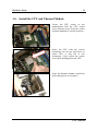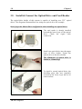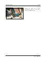
1
AB-2003 DigiDice
Socket 478 Mini PC System
User’s Manual
4200-0382-24
Rev. 1.01
Copyright and Warranty Notice
The information in this document is subject to change without notice and does not
represent a commitment on part of the vendor, who assumes no liability or
responsibility for any errors that may appear in this manual.
No warranty or representation, either expressed or implied, is made with respect to the
quality, accuracy or fitness for any particular part of this document. In no event shall
the manufacturer be liable for direct, indirect, special, incidental or consequential
damages arising from any defect or error in this manual or product.
Product names appearing in this manual are for identification purpose only and
trademarks and product names or brand names appearing in this document are
property of their respective owners.
This document contains materials protected under International Copyright Laws. All
rights reserved. No part of this manual may be reproduced, transmitted or transcribed
without the expressed written permission of the manufacturer and authors of this
manual.
AB-2003 DigiDice
Safety Instructions
1. Please read these safety instructions carefully.
2. Please keep this User’s Manual for later reference.
3. Please disconnect this equipment from AC outlet before cleaning or inserting any
add-on card or module.
4. Don’t use liquid or sprayed detergent for cleaning. Use moisture sheet or cloth for
cleaning.
5. Please keep this equipment away from humidity.
6. Lay this equipment on a reliable surface when install. A drop or fall could cause
injury.
7. Place the power cord in such a way that people can not step on it. Do not place
anything over the power cord.
8. All cautions and warnings on the equipment should be noted.
9. If this equipment is not use for a long time, disconnect the equipment from mains
to avoid being damaged by transient voltage.
10. Never pour any liquid into opening; this could cause fire or electrical shock.
11. If one of the following situations arises, get the equipment checked by service
personnel:
a. The power cord or plug is damaged.
b. Liquid has penetrated into the equipment.
c. The equipment has been exposed to moisture.
d. The equipment has not work well or you can not get it work according to
User’s Manual.
e. The equipment has dropped and damaged.
f. The equipment has obvious sign of breakage.
12. This equipment can be operated at maximum ambient temperature of 40oC.
13. Lithium battery provided, pay attention about this replaceable battery for safety
reason.
“CAUTION – Risk of explosion if battery is incorrectly replaced. Dispose of
used batteries according to the instructions.”
User’s Manual
AB-2003 DigiDice
Table Of Contents
Chapter 1.
1.1.
1.2.
1.3.
1.4.
1.5.
1.6.
1.7.
1.8.
1.9.
1.10.
1.11.
Chapter 2.
2.1.
2.2.
Introduction .................................................... 1-1
Overview............................................................................................1-1
Features..............................................................................................1-1
Installation Notice..............................................................................1-2
Specifications.....................................................................................1-3
Parts Checklist ...................................................................................1-5
Front Panel.........................................................................................1-7
Rear Panel ..........................................................................................1-8
Function Keys ....................................................................................1-9
Dual Optical Drive Bays..................................................................1-10
LCD Screen .....................................................................................1-11
Remote Controller ...........................................................................1-12
1.11.1. WinDVD Operation..........................................................1-13
1.11.2. WinRip Operation.............................................................1-14
1.11.3. Photo Review Operation...................................................1-15
Knowing Your Motherboard ........................ 2-1
Layout Diagram .................................................................................2-1
Connectors, Headers and Switches....................................................2-2
2.2.1.
ATX Power Input Connectors ............................................2-2
2.2.2.
FAN Connectors .................................................................2-3
2.2.3.
CMOS Memory Clearing Header.......................................2-4
2.2.4.
Accelerated Graphics Port Slot...........................................2-5
2.2.5.
PCI Slot...............................................................................2-6
2.2.6.
Front Panel Switches & Indicators Connection Headers....2-7
2.2.7.
Additional USB Port Connection Header...........................2-9
2.2.8.
LCM1 Connector ..............................................................2-10
2.2.9.
Internal Audio Source Connectors ...................................2-11
2.2.10. IDE Disk Drive Connectors..............................................2-12
2.2.11. Serial ATA Connectors.....................................................2-13
2.2.12. Front Panel I/O .................................................................2-14
User’s Manual
2.2.13.
Chapter 3.
3.1.
3.2.
3.3.
3.4.
3.5.
3.6.
3.7.
3.8.
3.9.
Hardware Setup.............................................. 3-1
Precautions.........................................................................................3-1
Remove The Chassis Cover...............................................................3-2
Install The Memory Module ..............................................................3-4
Install the CPU and Thermal Module ................................................3-5
Install & Connect the Optical Drive and Card Reader ......................3-8
Install the System Fan......................................................................3-12
Install the AGP or PCI Expansion Card ..........................................3-14
Install the IDE Hard Drive...............................................................3-16
Install the Essential Oil Tank...........................................................3-19
Chapter 4.
4.1.
4.2.
4.3.
4.4.
4.5.
4.6.
4.7.
4.8.
4.9.
4.10.
4.11.
4.12.
4.13.
4.14.
BIOS Setup...................................................... 4-1
SoftMenu Setup .................................................................................4-2
Standard CMOS Features ..................................................................4-4
Advanced BIOS Features ..................................................................4-7
Advanced Chipset Features .............................................................4-10
Integrated Peripherals ......................................................................4-12
Power Management Setup ...............................................................4-18
PnP/PCI Configurations...................................................................4-20
PC Health Status ..............................................................................4-22
Load Fail-Safe Defaults ...................................................................4-24
Load Optimized Defaults.................................................................4-24
Set Supervisor Password..................................................................4-24
Set User Password ...........................................................................4-24
Save & Exit Setup............................................................................4-24
Exit Without Saving ........................................................................4-24
Chapter 5.
5.1.
Rear Panel I/O...................................................................2-15
Driver Setup.................................................... 5-1
Setup Items ........................................................................................5-2
AB-2003 DigiDice
Chapter 6.
6.1.
6.2.
6.3.
6.4.
6.5.
6.6.
6.7.
Exercising Your DigiDice .............................. 6-1
Prior To Powering On The System....................................................6-1
Easy OC (Over Clocking) Setting .....................................................6-2
Powering On The System ..................................................................6-4
Hot Key Controlling ..........................................................................6-5
ABIT EQ and ABIT Manager ...........................................................6-7
Memory Card Reading ....................................................................6-11
Powering Off The System ...............................................................6-12
Appendix A. How to Get Technical Support ..................... A-1
User’s Manual
AB-2003 DigiDice
Introduction
Chapter 1.
1-1
Introduction
1.1. Overview
DigiDice is a mainstream P4 platform mini pc barebone with superior
over-clocking ability & optional RAID function in a small case which
provides a 6-in-1Card Reader function, two external 5.25” device bays and
two internal 3.5” device bays for ultimate flexibility.
In addition, the front LCD display offers useful system information, and the
Hot Key design makes the system user-friendlier for specific PC functions.
Let DigiDice bring you an amazing video/ audio and PC experience.
1.2. Features
Dust Covers
Two automatic front covers protect your optical drive bay from dusting
problem; this appropriate design also makes the entire system more stylish.
Two 5.25-inch Bays
The spacious room allows dual optical drives installation. A tiny but complete
CD disk copy station is realized at once.
Four Hot Keys
Four hot-keys in the front panel allow DVD/VCD video play back, CD/MP3
audio play back, photo viewing, and CD copying by just one click.
AGP/PCI Slot
A system upgrade is easy to reach through additional AGP and PCI slot. You
can upgrade to a powerful VGA card or add on a PCI TV-Tuner card.
Dual Channel DDR & SATA RAID
Dual Channel DDR provides maximum memory performance by up to 50%
compared to the one of standard DDR memory. SATA RAID (optional)
provides maximum data transfer rate with high data security simultaneously.
OTES Thermal Solution
ABIT’s exclusive OTES thermal solutions are applied for two objectives:
extremely low system temperature and system noise. OTES monitors both
system loading and system temperature to meet the low noise requirement via
controlling internal thermal system.
User’s Manual
1-2
Chapter 1
EZ OC (Over Clocking) Setting
Two different ways of Over Clocking your system are available. You can
either go with 5-level automatic OC (EZ OC) by using knob controller in the
front panel, or with ABIT’s exclusive SoftMenu BIOS setting.
ABIT EQ
System status can be monitored both through the LCD screen on front panel,
and the “ABIT EQ” software-based application.
Remote Control
A handy remote controller is also bundled in the package. You can control and
launch programs from distance.
1.3. Installation Notice
•
•
•
Compatible with Windows XP operation system only
Must be applied together with “ABIT Manager”
Must use in collocation with the application software bundled
AB-2003 DigiDice
Introduction
1-3
1.4. Specifications
CPU
•
•
Supports Intel Pentium 4 Socket 478 processor with 800MHz,
533MHz, and 400MHz (for Northwood only) FSB
Supports Intel Hyper-Threading Technology
Chipset
•
•
Intel 82865G (MCH) + 82801EB (ICH5)
Integrated Intel “Extreme Graphics 2” graphics controller
Memory
•
Two DDR DIMM sockets support DDR 266/333/400 memory module
up to 2GB
Expansion slot
•
•
1x AGP slot, two standard slot space for ABIT OTES AGP card
1x PCI slot
IDE
•
2x ATA100 channels and 2x Serial ATA channels
LAN
•
10/100Mbit LAN
Audio
•
5.1 channel AC97 CODEC
ABIT Engineered
•
•
•
ABIT SoftMenu™ Technology
ABIT Manager utility
Hardware Monitoring - Including Fan speed, Voltages, CPU and
System Temperature
Front Panel I/O
•
•
•
•
•
1x IEEE 1394 connector
2x USB 2.0 connectors
1x MIC connector
1x Headphone connector
1x 6-in-1 card reader support SM, MMC, SD, CMS, CF, Micro drive
User’s Manual
1-4
Chapter 1
•
•
•
1x LCD display
4x Hot-keys
1x Knob button
Back Panel I/O
•
•
•
•
1x PS/2 Keyboard, 1x PS/2 Mouse
1x VGA Out connector
1x Audio connector (Speaker, Line-out, Line-in, Mic-in,
Center/Sub-woofer and SPDIF Out connector)
2x USB 2.0 Connectors, 1x RJ-45 LAN Connector
Chassis Material
•
Aluminum
Bezel Color
•
Silver
Bundle Software
•
•
InterVideo WinDVD
InterVideo WinRip with MP3 encoder
Dimension
•
307 x 215 x 255mm (W x H x D) with foot stand
Drive Bays
•
•
2x 5.25” for optical devices
2x 3.5” for HDD
Power Supply
•
AC 100V~240V 50/60Hz input. Maximum 200W output with PFC
function.
Specifications and information contained herein are subject to change
without notice.
AB-2003 DigiDice
Introduction
1-5
1.5. Parts Checklist
Item
Photo
Quantity
ATA/100 IDE Cable
1
ATA/33 IDE Cable
1
CPU Thermal Module
1
Driver & Utility CD
1
Fan Duct
1
Power Cord (Types differ
depending on version)
1
System Fan
1
User’s Manual
1
Quick Installation Guide
1
User’s Manual
1-6
Chapter 1
Carrying Bag (bonus parts for
deluxe version)
1
Essential Oil (bonus parts for
deluxe version)
1
Essential Oil Tank (bonus parts
for deluxe version)
1
Remote Controller (bonus parts
for deluxe version)
1
AB-2003 DigiDice
Introduction
1-7
1.6. Front Panel
1.
Hot Keys
6.
Knob Controller
2.
LCD Screen
7.
Microphone Jack
3.
IR Receiver Sensor
8.
Headphone Jack
4.
Card Reader Slot
9.
USB 2.0 Connector
5.
5.25” Empty Tray
(For Optical Drive)
10. IEEE 1394 Connector
User’s Manual
1-8
Chapter 1
1.7. Rear Panel
1.
AC Power Cord Connector
6.
5.1 Audio Connector
2.
PS/2 Keyboard Connector
7.
USB 2.0 Connector
3.
PS/2 Mouse Connector
8.
LAN Connector
4.
VGA Out Connector
9.
I/O Shield for AGP Slot
5.
S/PDIF Out Connector
10. I/O Shield for PCI Slot
AB-2003 DigiDice
Introduction
1-9
1.8. Function Keys
There are four Hot Keys and one
Knob Controller on the front panel.
Each button is provided with its
multi control function. An infrared
receiver sensor is also equipped for
a remote convenience.
Knob Controller:
•
Power on/off
•
Easy OC and hard ware
monitor
•
Confirmation
•
Volume output level
Video Control:
•
Toggles the video playing
program (WinDVD)
Audio Control:
•
Toggles the audio playing program (WinRip)
Photo Control:
•
Toggles the photo viewing program (Windows XP Photo Browser)
Copy Control:
•
Toggles the CD copy program (DigiBurner) (This function only works
in the collocation of two optical disks (one CD/DVD-ROM and one
CD-R/CD-RW).
Infrared Receiver Sensor:
•
Infrared receiver sensor for remote controller.
NOTE: These function keys work only after the [ABIT Manager] utility is
toggled on.
User’s Manual
1-10
Chapter 1
1.9. Dual Optical Drive Bays
Two 5.25-inch empty bays at the front panel are available for installing two
optical drives.
Dust Cover: The disk plate of your optical drive will be ejected through
this cover plate after pressing the eject button.
Eject Button: Press this button to eject the optical drive. (You may have
do a little adjusting if the disk plate of your optical drive cannot be ejected
by pressing this button: Slide the pointer on the adjusting rod behind this
button so as to make it touches the eject button on optical drive.)
AB-2003 DigiDice
Introduction
1-11
1.10. LCD Screen
Video Playing
Temperature
Audio Playing
Fan Running
Photo Viewing
Disk Over-load
Copying Mode
Network Connecting
Volume Level
System Suspend
Alarm Alert
User’s Manual
1-12
Chapter 1
1.11. Remote Controller
This mini PC is equipped with a remote controller, supporting the control function of
WinDVD, WinRip, and Photo Review from distance. This easy control grants you an
easy-to-reach AV entertainment.
This remote controller is powered by two AAA-size batteries. Point the infrared
transmitter of the remote controller to the infrared receiver sensor on the front panel
when accessing a remote command.
AB-2003 DigiDice
Introduction
1-13
1.11.1. WinDVD Operation
System power on/off
WinDVD Launch/Close WinDVD
Mute Mute the volume
Root Menu Enter the rootmenu
Bookmark
Enter the bookmark
menu
Screen Full Screen/Windows
Audio Language Selection
Subtitle Enter the subtitle
Viewangle Adjust the viewing angle
Playlist View the play list
Volume Increase
Volume Decrease
Escape
Step Forward Move one step forward
Menu Enter the menu screen
Up, Down, Left, Right
Arrow, and Enter button
Fast Backward
Play/Pause
Fast Forward
Last Chapter
Stop
Next Chapter
User’s Manual
1-14
Chapter 1
1.11.2. WinRip Operation
Power On/Off
WinRip Launch/Close WinRip
Mute Mute the volume
Playlist View the play list
Volume Increase
Volume Decrease
Escape
Up, Down, Left, Right
Arrow, and Enter button
Record
Shuffle (Random play)
Play/Pause
Repeat
Last Track
Stop
Next Track
Jukebox
DSP (Enter digital signal
processing menu)
Gallery
Select All Select all tracks
Audio CD Select audio CD
AB-2003 DigiDice
Introduction
1-15
1.11.3. Photo Review Operation
Power On/Off
Up, Down, Left, Right
Arrow, and Enter button
Launch Photo Review
Last Page
Start/Pause (Automatic
Viewing)
Next Page
Rotate Left
Stop (Automatic
Viewing)
Rotate Right
Zoom In
Zoom Out
Print
User’s Manual
1-16
AB-2003 DigiDice
Chapter 1
Knowing Your Motherboard
Chapter 2.
2-1
Knowing Your Motherboard
2.1. Layout Diagram
User’s Manual
2-2
Chapter 2
2.2. Connectors, Headers and Switches
WARNING: Always power off the computer and unplug the AC power cord before
adding or removing any peripheral or component. Failing to so may cause severe
damage to your motherboard and/or peripherals. Plug in the AC power cord only after
you have carefully checked everything.
2.2.1.
ATX Power Input Connectors
Connects to ATX power supply.
AB-2003 DigiDice
Knowing Your Motherboard
2.2.2.
2-3
FAN Connectors
These 3-pin connectors each provide power to the cooling fans installed in your
system.
The CPU must be kept cool by using a powerful fan with heatsink. The system is
capable of monitoring the speed of the CPU fan.
•
CPUFAN1: CPU Fan
•
SYSFAN1: System Fan
•
AUXFAN1: Auxiliary Fan
•
NBFAN1: N.B. Chipset Fan
WARNING: These fan connectors are not jumpers. DO NOT place jumper caps on
these connectors.
User’s Manual
2-4
2.2.3.
Chapter 2
CMOS Memory Clearing Header
This header uses a jumper cap to clear the CMOS memory.
•
Pin 1-2 shorted (default): Normal operation.
•
Pin 2-3 shorted: Clear CMOS memory.
ATTENTION: Turn the system power off first (including the +5V standby power)
before clearing the CMOS memory. Failing to do so may cause your system to work
abnormally or malfunction.
AB-2003 DigiDice
Knowing Your Motherboard
2.2.4.
2-5
Accelerated Graphics Port Slot
This slot allows you to connect monitor through an optional AGP card instead of the
onboard VGA Out Connector.
ATTENTION: This motherboard does not support 3.3V AGP cards. Use only 1.5V
or 0.8V AGP cards.
User’s Manual
2-6
2.2.5.
Chapter 2
PCI Slot
The PCI slot allows you to insert PCI card or TV Tuner card.
AB-2003 DigiDice
Knowing Your Motherboard
2.2.6.
2-7
Front Panel Switches & Indicators Connection Headers
These headers are used for connecting switches and LED indicators on the chassis
front panel. The mark “+” align to the pin in the figure below stands for positive
polarity for the LED connection.
•
HLED (Pin 1, 3):
Connects to the HDD LED cable of chassis front panel.
•
RST (Pin 5, 7):
Connects to the Reset Switch cable of chassis front panel.
•
SPK (Pin 15, 17, 19, 21):
Connects to the System Speaker cable of chassis.
•
SLED (Pin 2, 4):
Connects to the Suspend LED cable (if there is one) of chassis front panel.
User’s Manual
2-8
Chapter 2
•
PWR-ON (Pin 6, 8):
Connects to the Power Switch cable of chassis front panel.
•
PLED (Pin 16, 18, 20):
Connects to the Power LED cable of chassis front panel.
AB-2003 DigiDice
Knowing Your Motherboard
2.2.7.
2-9
Additional USB Port Connection Header
This header provides 2 additional USB 2.0 ports connection through an USB cable
designed for USB 2.0 specifications.
Pin
1
3
5
7
9
Pin Assignment
VCC
Data0 Data0 +
Ground
NC
Pin
2
4
6
8
10
Pin Assignment
VCC
Data1 Data1 +
Ground
NC
User’s Manual
2-10
2.2.8.
Chapter 2
LCM1 Connector
This connector connects to the LM-01 controller board located inside front panel.
AB-2003 DigiDice
Knowing Your Motherboard
2.2.9.
2-11
Internal Audio Source Connectors
These connectors connect to the audio output of internal CD-ROM drive or add-on
card.
User’s Manual
2-12
Chapter 2
2.2.10. IDE Disk Drive Connectors
These IDE ports each connects up to two
IDE drives at Ultra ATA/100 mode by one
40-pin, 80-conductor, and 3-connector Ultra
ATA/66 ribbon cables. Connect the single
end (blue connector) at the longer length of
ribbon cable to the IDE port on system
board, and the other two ends (gray and
black connector) at the shorter length of the
ribbon cable to the connectors on hard
drives.
NOTE: The red line on the ribbon cable should be aligned with pin-1 on this
connector.
AB-2003 DigiDice
Knowing Your Motherboard
2-13
2.2.11. Serial ATA Connectors
These connectors are provided to attach one Serial ATA device at each channel via
Serial ATA cable.
User’s Manual
2-14
Chapter 2
2.2.12. Front Panel I/O
•
JK2: Microphone Jack
•
JK1: Headphone Jack
•
USB1: USB 2.0 Connectors
•
FP-1394-1: IEEE 1394 Connector
AB-2003 DigiDice
Knowing Your Motherboard
2-15
2.2.13. Rear Panel I/O
•
Mouse: Connects to PS/2 mouse.
•
Keyboard: Connects to PS/2 keyboard.
•
VGA1: Connects to monitor input.
•
AUDIO1:
R.L./R.R. (Rear Left / Rear Right): Connects to the rear left and rear right
channel in the 5.1 channel audio system.
Cen./Sub. (Center / Subwoofer): Connects to the center and subwoofer
channel in the 5.1 channel audio system.
S/PDIF Out: This connector provides an S/PDIF out connection through
optical fiber to digital multimedia devices.
Mic In: Connects to the plug from external microphone.
Line In: Connects to the line out from external audio sources.
F.L./F.R. (Front Left / Front Right): Connects to the front left and front
right channel in the 5.1-channel or regular 2-channel audio system.
•
LAN: Connects to Local Area Network.
•
USB2: USB 2.0 Connectors
User’s Manual
2-16
AB-2003 DigiDice
Chapter 2
Hardware Setup
Chapter 3.
3-1
Hardware Setup
3.1. Precautions
Please pay attention to the following precautions before setting up any hardware.
1. Always switch off the power supply and unplug the power cord from the wall
outlet before installing the board or changing any settings.
2. Ground yourself properly by wearing a static safety wrist strap before removing
the board from the antistatic bag.
3. Hold the board by its edges. Avoid touching any component on it.
4. Avoid touching module contacts and IC chips
User’s Manual
3-2
Chapter 3
3.2. Remove The Chassis Cover
Unscrew the four screws at the rear
side of the system chassis by fingers.
Pull the upper cover backward for
about 2cm.
Lift up the upper cover.
AB-2003 DigiDice
Hardware Setup
3-3
Pull out the card-reader plug from
FP-USB1 header.
Unscrew the optical-drive
hard-drive holder.
and
Take out the optical-drive
hard-drive holder.
and
This system is now ready to install the
interior devices.
User’s Manual
3-4
Chapter 3
3.3. Install The Memory Module
Locate the DIMM slot on the
motherboard. Hold two edges of the
DIMM module carefully, keep away
of touching its connectors. Align the
notch key on the module with the rib
on the slot. Watch out for the
direction, since the module fits in one
direction only.
Static electricity can damage the
electronic components of the
computer or optional boards. Before
starting these procedures, ensure
that you are discharged of static
electricity by touching a grounded
metal object briefly.
Firmly press the module into the slots
by both thumbs until the ejector tabs
at both sides of the slot automatically
snaps into the mounting notch. Do not
force the DIMM module in with extra
force as the DIMM module only fit in
one direction.
The memory
installed.
AB-2003 DigiDice
module
is
firmly
Hardware Setup
3-5
3.4. Install the CPU and Thermal Module
Locate the CPU socket on the
motherboard. Pull the CPU socket
lever sideways away from the socket
and then upwards to vertical position.
Insert the CPU with the correct
orientation. Do not use extra force to
insert CPU; it only fits in one
orientation. Close down the socket
lever while holding down the CPU.
Align the thermal module toward the
heat-sinking hole at rear panel.
User’s Manual
3-6
Chapter 3
Put the thermal module onto the CPU
die. Align the four screws on thermal
module with the four screw holes on
motherboard.
Use the rubber buckle to fasten the
fan-duct by the order of 1 through 3.
Pass the fan-power plug of the
fan-duct through the I/O shield into
the chassis.
Connect the fan-power plug of the
fan-duct to the SYSFAN1 header on
motherboard.
AB-2003 DigiDice
Hardware Setup
3-7
Use one rubber buckle to fasten the
fan-duct through the chassis with the
external heat sink of thermal module.
Fasten the screw hole of fan-duct onto
rear panel.
Watch out for the tension laid on
screws when fastening.
Fasten the four screws on thermal
module by the order of 1 through 4.
Connect the fan-power plug of the
thermal module to the CPU FAN1
header on the motherboard.
User’s Manual
3-8
Chapter 3
3.5. Install & Connect the Optical Drive and Card Reader
The optical-drive holder of this system is capable of installing two 5.25” optical
drives. The diagrams illustrated here are using one optical drive for example.
Don’t forget the Master/Slave configuration when installing two optical drives.
The card reader is already installed
beneath the lower layer of the optical
drive. Check the signal cable
connection.
Install one optical drive into the upper
layer of drive holder. Fasten the
optical drive to the drive holder.
The dimension of optical drive is
limited to 199mm deep.
To install a second optical drive, the
shielding plate that was originally
secured at the lower layer has to be
removed first.
AB-2003 DigiDice
Hardware Setup
3-9
Pass the optical drive cable through
the cable hole.
Connect the signal and audio cable to
the optical drive.
Connect the power cord to optical
drive.
Slide in the holder into the chassis by
45 degree.
User’s Manual
3-10
Chapter 3
Align the screw holes with the holes
on the chassis.
Fasten the optical-drive holder to the
chassis.
Connect the card-reader plug back to
FP-USB1 header.
Connect the audio cable from the
connector
of
audio-out
on
optical-drive to the CD1 on
motherboard.
AB-2003 DigiDice
Hardware Setup
3-11
Connect the other side of the
optical-drive cable to the IDE2
connector on motherboard.
User’s Manual
3-12
Chapter 3
3.6. Install the System Fan
Take out system fan and its rubber
buckle.
Fasten the system fan to the chassis
with four rubber buckles.
Identify the air-blow direction. Make
sure to install the fan so as to blow
the air out.
AB-2003 DigiDice
Hardware Setup
3-13
Firmly press in the four rubber
buckles.
Connect the fan-power plug of the
system fan to the AUX FAN1 header
on motherboard.
User’s Manual
3-14
Chapter 3
3.7. Install the AGP or PCI Expansion Card
Besides the onboard VGA out, the motherboard of this system also provides one extra
AGP and one PCI slot to install AGP or PCI add-on card, such as VGA card, Modem
card, or LAN card.
These steps are used for installing additional AGP and PCI add-on card. Skip these
steps if there are no such needs.
Unscrew the I/O shield support.
Take off the I/O shield support.
Take off the I/O shield of the slot you
want to install add-on card.
AB-2003 DigiDice
Hardware Setup
3-15
Connect the AGP or PCI add-on card
(read its instruction manual first).
Press down the AGP or PCI add-on
card into the slot.
Screw back the I/O shield support by
fingers.
The dimension of add-on VGA and PCI card is limited to 113mm high and 217mm deep (not
including the I/O shield plate).
Connect your monitor to the VGA output on this add-on AGP card.
User’s Manual
3-16
Chapter 3
3.8. Install the IDE Hard Drive
The hard-drive holder of this system is capable of installing two 3.5” hard drives. The
diagrams illustrated here are using one IDE hard drive for example.
Don’t forget the Master/Slave configuration when installing two hard drives.
If you want to install ATA and SATA hard drive together, make sure to install the
SATA hard drive at the upper layer.
Install one IDE hard drive into the
bay. Fasten the hard drive to its
holder.
Connect the signal cable to the hard
drive.
Pay attention to the Master/Slave
configuration no matter installing
one or two optical drives.
AB-2003 DigiDice
Hardware Setup
3-17
Connect the power cord.
Insert the hard-drive holder vertically
down into the chassis.
Fasten the hard-drive holder to the
chassis.
Connect the other side of the IDE
cable to the IDE1 connector on
motherboard.
User’s Manual
3-18
Chapter 3
Do the final check to make sure
everything is installed OK. Now you
can put back the upper cover and
screw the chassis.
AB-2003 DigiDice
Hardware Setup
3-19
3.9. Install the Essential Oil Tank
Press the essential oil tank (bonus
parts for deluxe version) firmly into
the ditches of external heat sink.
Pour in a few drops of essential oil
(bonus parts for deluxe version) into
the tank. The heat dissipated from
external heat sink will gradually
vaporize the oil flavor.
Safety and Storage Precautions when dealing with the essential oil
•
Never ignite the essential oil directly.
•
Never heat the essential by fire in any containers.
•
Never take by mouth.
•
Keep away from skin and eyes.
•
Store in a dry, cool place away from direct sunlight.
User’s Manual
3-20
AB-2003 DigiDice
Chapter 3
BIOS Setup
Chapter 4.
4-1
BIOS Setup
This motherboard provides a programmable EEPROM that you can update the BIOS
utility. The BIOS (Basic Input/Output System) is a program that deals with the basic
level of communication between processor and peripherals. Use the BIOS Setup
program only when installing motherboard, reconfiguring system, or prompted to
“Run Setup”.
After powering up the system, the BIOS message appears on the screen, the memory
count begins, and then the following message appears on the screen:
Press DEL to run setup
If this message disappears before you respond, restart the system by pressing <Ctrl> +
<Alt> + <Del> keys, or by pressing the Reset button on computer chassis. Only when
it failed by these two methods can you restart the system by powering it off and then
back on.
After pressing <Del> key, the main menu screen appears.
NOTE: In order to increase system stability and performance, our engineering staffs
are constantly improving the BIOS menu. The BIOS setup screens and descriptions
illustrated in this manual are for your reference only, may not completely match what
you see on your screen.
User’s Manual
4-2
Chapter 4
4.1. SoftMenu Setup
The SoftMenu utility is ABIT’s exclusive and ultimate solution in programming the
CPU operating speed. All the parameters regarding CPU FSB speed, multiplier factor,
the AGP & PCI clock, and even the CPU core voltage are all available at your
fingertips.
CPU Operating Speed:
This item displays the CPU operating speed according to the type and speed of your
CPU. You can also select the [User Define] option to enter the manual option.
CPU FSB Clock (MHz):
This item selects the external clock frequency.
Multiplier Factor:
This item selects the multiplier factors for your CPU if it is not locked.
N/B Strap CPU As:
This item sets the external hardware reset strap assigned to MCH (Memory Controller
Hub).
To set this option manually:
•
Select [PSB400] for CPU of 100MHz FSB frequency.
AB-2003 DigiDice
BIOS Setup
•
Select [PSB533] for CPU of 133MHz FSB frequency.
•
Select [PSB800] for CPU of 200MHz FSB frequency.
4-3
DRAM Ratio (CPU:DRAM):
This item determines the frequency ratio between CPU and DRAM.
AGP Ratio (CPU:AGP:PCI):
This item determines the ratio among CPU, AGP, and PCI.
Fixed AGP/PCI Frequency:
This item determines the AGP/PCI bus frequency. This option allows you to keep
your AGP/PCI clock at some fixed frequency to improve system stability.
CPU Power Supply:
This option allows you to switch between CPU default and user-defined voltages.
Leave this setting to default unless the current CPU type and voltage setting cannot be
detected or is not correct. The option [User Define] enables you to select the Core
Voltage manually.
CPU Core Voltage:
This item selects the CPU core voltage.
ATTENTION: A wrong voltage setting may cause the system unstable or even
damage the CPU. Please leave it to default settings unless you are fully aware of its
consequences.
DRAM Voltage:
This item selects the voltage for DRAM slot.
AGP Voltage:
This item selects the voltage for AGP slot.
User’s Manual
4-4
Chapter 4
4.2. Standard CMOS Features
Date (mm:dd:yy)
This item sets the date you specify (usually the current date) in the format of [Month],
[Date], and [Year].
Time (hh:mm:ss)
This item sets the time you specify (usually the current time) in the format of [Hour],
[Minute], and [Second].
AB-2003 DigiDice
BIOS Setup
4-5
IDE Channel 1Master / Slave and IDE Channel 2 Master / Slave:
Click <Enter> key to enter its submenu:
IDE HDD Auto-Detection:
This item allows you to detect the parameters of IDE drives by pressing the <Enter>
key. The parameters will automatically be shown on the screen.
IDE Channel 1 Master:
When set to [Auto], the BIOS will automatically check what kind of IDE drive you
are using. If you want to define your own drive by yourself, set it to [Manual] and
make sure you fully understand the meaning of the parameters. Refer to the manual
provided by the device manufacturer to get the settings right.
Access Mode:
This item selects the mode to access your IDE devices. Leave this item to its default
[Auto] settings to let BIOS detects the access mode of your HDD and makes decision
automatically.
Capacity:
This item automatically displays your HDD size. Note that this size is usually slightly
greater than the size given by a disk-checking program of a formatted disk.
User’s Manual
4-6
Chapter 4
NOTE: The following [Cylinder], [Head], [Precomp], [Landing Zone], and [Sector]
items are available when you set the item “IDE Primary Master” to “Manual”.
Cylinder:
This item configures the numbers of cylinders.
Head:
This item configures the numbers of read/write heads.
Precomp:
This item displays the number of cylinders at which to change the write timing.
Landing Zone:
This item displays the number of cylinders specified as the landing zone for the
read/write heads.
Sector:
This item configures the numbers of sectors per track.
Back to Standard CMOS Features Setup Menu
Halt On:
This item determines whether the system stops if an error is detected during system
boot-up.
[All Errors]: The system-boot will stop whenever the BIOS detect a non-fatal error.
[No Errors]: The system-boot will not stop for any error detected.
[All, But Keyboard]: The system-boot will stop for all errors but keyboard error.
Base Memory:
This item displays the amount of base memory installed in the system. The value of
the base memory is typically 640K for system with 640K or more memory size
installed on the motherboard.
Extended Memory:
This item displays the amount of extended memory detected during system boot-up.
Total Memory:
This item displays the total memory available in the system.
AB-2003 DigiDice
BIOS Setup
4-7
4.3. Advanced BIOS Features
BIOS Protect Control:
This option protects for accidentally BIOS writing attempt.
NOTE: Make sure to set this item to “Unprotected” when flashing the BIOS.
Hard Disk Boot Priority:
This item selects the hard disks booting priority. By pressing <Enter> key, you can
enter its submenu where the hard disks detected can be selected for the booting
sequence to boot up system.
This item functions only when there is the option of [Hard Disk] in any one of the
First/Second/Third Boot Device items.
Quick Power On Self Test:
When set to [Enabled], this item speeds up the Power On Self Test (POST) after
powering on the system. The BIOS shorten or skip some check during the POST.
User’s Manual
4-8
Chapter 4
Hard Disk Boot Priority:
This item selects the hard disks booting priority. By pressing <Enter> key, you can
enter its submenu where the hard disks detected can be selected for the booting
sequence to boot up system.
This item functions only when there is the option of [Hard Disk] in any one of the
First/Second/Third Boot Device items.
First Boot Device / Second Boot Device / Third Boot Device / Boot Other Device:
This item selects the drive to boot first, second and third in the [First Boot Device],
[Second Boot Device], and [Third Boot Device] fields respectively. The BIOS will
boot the operating system according to the sequence of the drive selected. Set [Boot
Other Device] to [Enabled] if you wish to boot from another device other than these
three items.
Boot Up NumLock Status:
This item determines the default state of the numeric keypad at system booting up.
[On]: The numeric keypad functions as number keys.
[Off]: The numeric keypad functions as arrow keys.
AB-2003 DigiDice
BIOS Setup
4-9
Security Option:
This item determines when the system will prompt for password - every time the
system boots or only when enters the BIOS setup.
[Setup]: The password is required only when accessing the BIOS Setup.
[System]: The password is required each time the computer boots up.
NOTE: Don’t forget your password. If you forget the password, you will have to
open the computer case and clear all information in the CMOS before you can start up
the system. But by doing this, you will have to reset all previously set options.
MPS Version Ctrl For OS:
This item specifies which version of MPS (Multi-Processor Specification) this
motherboard will use. Leave this item to its default setting.
Intel OnScreen Branding:
This item determines whether to display the “Intel Inside” logo or not at system boots
up.
User’s Manual
4-10
Chapter 4
4.4. Advanced Chipset Features
DRAM Timing Selectable:
This item sets the optimal timings for the following four items, depending on the
memory module you are using. The default setting “By SPD” configures these four
items by reading the contents in the SPD (Serial Presence Detect) device. The
EEPROM on the memory module stores critical parameter information about the
module, such as memory type, size, speed, voltage interface, and module banks.
CAS Latency Time:
This item controls the latency between the DRAM read command and the time that
the data becomes actually available.
Act to Precharge Delay:
This item controls the number of DRAM clocks used for the DRAM parameters.
DRAM RAS# to CAS# Delay
This item controls the latency between the DRAM active command and the read/write
command.
DRAM RAS# Precharge:
This item controls the idle clocks after issuing a precharge command to the DRAM.
AB-2003 DigiDice
BIOS Setup
4-11
AGP Aperture Size:
This option specifies the amount of system memory that can be used by the AGP
device. The aperture is a portion of the PCI memory address range dedicated for
graphics memory address space.
Init Display First:
This item selects to initialize AGP or PCI Slot first when the system boots.
[AGP]: When the system boots, it will first initialize AGP.
[PCI Slot]: When the system boots, it will first initialize PCI.
Game Accelerator:
This item selects the mode for Game Accelerator among the options of [Auto],
[Turbo], [Street Racer], and [F1].
NOTE: The option [Street Racer] and [F1] mode will stress the DDR memory
critically; not every kind of DDR memories could be stable with these two options.
[Turbo] mode is okay for most of DDR memories.
Refresh Cycle Time:
This item determines the DRAM Refresh Cycle among [Auto], [Normal], [Enhanced],
[Strengthened], and [Aggressive].
Read Delay (tRD):
This item determines the timing of DRAM Read Delay.
Read delay Adjust(tRDA):
This item determines to adjust the timing of DRAM Read Delay.
Command Per Clock(CPC):
This item determines the address command timing according to the DRAM strobe
clock.
On-Chip VGA:
This option enables or disables the on-chip VGA controller.
Frame Buffer Size:
This option selects the size of on-chip frame buffer.
User’s Manual
4-12
Chapter 4
4.5. Integrated Peripherals
Onboard IDE Device:
Click <Enter> key to enter its submenu:
AB-2003 DigiDice
BIOS Setup
4-13
IDE Bus Master:
This option enables or disables the IDE bus mastering capability under the DOS
environment.
Onboard IDE-1 Controller:
This item enables or disables the onboard IDE-1 controller.
Onboard IDE-2 Controller:
This item enables or disables the onboard IDE-2 controller.
Onboard S-ATA Controller:
This item determines the function for on-chip Serial ATA.
[Disabled]: Disable the Serial ATA controller.
[Auto]: Allows the Serial ATA controller to be arranged by BIOS automatically.
[Combined Mode]: Parallel ATA and Serial ATA are combined together. Supports
up to 4 IDE drives.
[Enhanced Mode]: Enable both Parallel ATA and Serial ATA. Supports up to 6 IDE
drives.
[SATA Only]: The SATA is operating in legacy mode.
User’s Manual
4-14
Chapter 4
Serial ATA Port1 Mode / Serial ATA Port2 Mode:
This item determines the function mode for Serial ATA Port 1 (i.e. The SATA1
connector in this model) and Serial ATA Port 2 (i.e. The SATA2 connector in this
model). Both SATA1 and SATA2 will be served each as one single IDE connector
after selected as the following modes:
Mode
Serial ATA
Port 1
(SATA1)
Serial ATA
Description
Port 2 (SATA2)
IDE-3 Master
IDE-4 Master
IDE-4 Master
IDE-3 Master
IDE-1 Master
IDE-1 Slave
IDE-1 Slave
IDE-1 Master
IDE-2 Master
IDE-2 Slave
IDE-2 Slave
IDE-2 Master
S-ATA IDE1
S-ATA IDE2
S-ATA IDE2
S-ATA IDE1
Enhanced
Combined
SATA
Only
AB-2003 DigiDice
• SATA1 serves as IDE-3 Master
• SATA2 serves as IDE-4 Master
• OnChip IDE-1 and IDE-2
controller enabled
• SATA1 serves as IDE-4 Master
• SATA2 serves as IDE-3 Master
• OnChip IDE-1 and IDE-2
controller enabled
• SATA1 serves as IDE-1 Master
• SATA2 serves as IDE-1 Slave
• OnChip IDE-1 controller disabled
• SATA1 serves as IDE-1 Slave
• SATA2 serves as IDE-1 Master
• OnChip IDE-1 controller disabled
• SATA1 serves as IDE-2 Master
• SATA2 serves as IDE-2 Slave
• OnChip IDE-2 controller disabled
• SATA1 serves as IDE-2 Slave
• SATA2 serves as IDE-2 Master
• OnChip IDE-2 controller disabled
• SATA1 serves as IDE-1 Master
• SATA2 serves as IDE-2 Master
• OnChip IDE-1 and IDE-2
controller disabled
• SATA1 serves as IDE-2 Master
• SATA2 serves as IDE-1 Master
• OnChip IDE-1 and IDE-2
controller disabled
BIOS Setup
4-15
Onboard PCI Device:
Click <Enter> key to enter its submenu:
USB Controller:
This option enables or disables the USB controller.
USB 2.0 Controller:
This option enables or disables the USB 2.0 controller.
USB Keyboard Support:
This item allows you to select [BIOS] for using USB keyboard in DOS environment,
or [OS] in OS environment.
USB Mouse Support:
This item allows you to select [BIOS] for using USB mouse in DOS environment, or
[OS] in OS environment.
AC97 Audio:
When set to [Enabled], the onboard audio codec will be detected and supported. IF
you want to use audio adapter other than the one onboard, set this item to [Disabled]
Onboard LAN Device:
This item enables or disables the onboard LAN controller.
User’s Manual
4-16
Chapter 4
Onboard LAN Boot ROM:
When set to [Enabled], this item allows the system to boot from network by the
onboard LAN controller boot ROM.
Onboard 1394 Controller:
This item enables or disables the onboard IEEE 1394 controller.
SuperIO Device:
Click <Enter> key to enter its submenu:
POWER ON Function:
This item selects the way you want your system to power on.
[Password]: Use a password to power on the system, select this option then press
<Enter>. Enter your password. You can enter up to 5 characters. Type in exactly the
same password to confirm, and then press <Enter>.
[Hot Key]: Use any of the function keys between <F1> to <F12> to power on the
system.
[Mouse Left]: Double click the mouse left button to power on the system.
[Mouse Right]: Double click the mouse right button to power on the system.
[Any Key]: Use any keyboard keys to power on the system.
AB-2003 DigiDice
BIOS Setup
4-17
[Button Only]: Use only the power button to power on the system.
[Keyboard 98]: Use the power-on button on the “Keyboard 98” compatible keyboard
to power on the system.
NOTE: The mouse wake up function can only be used with the PS/2 mouse, not with
the COM port or USB type. Some PS/2 mice cannot wake up the system because of
compatible problems. If the specs of your keyboard are too old, it may fail to power
on.
KB Power ON Password:
This item sets the password required in order to power on your computer.
NOTE: Do not forget your password, or you will have to clear the CMOS and reset
all parameters in order to utilize this function again.
Hot Key Power ON:
This item powers on the system by pressing <Ctrl> key plus one of each function key
(<F1> ~ <F12>) simultaneously.
User’s Manual
4-18
Chapter 4
4.6. Power Management Setup
ACPI Suspend Type:
This item selects the type of Suspend mode.
[S1(POS)]: Enables the Power On Suspend function.
[S3(STR)]: Enables the Suspend to RAM function.
Run VGABIOS if S3 Resume:
Three options are available: Auto Yes No. The default setting is Auto. This
item can let you choose when S3 resume active, the VGA BIOS need to be initiative
or not.
USB Dev Wake-Up From S3:
When set to [Enabled], this item allows you to use a USB device to wake up a system
that is in the S3 (STR - Suspend To RAM) state. This item can only be configured if
the [ACPI Suspend Type] field is set to [S3(STR)].
Soft-Off by PWR-BTTN:
This item selects the method of powering off your system:
AB-2003 DigiDice
BIOS Setup
4-19
[Hold 4 Sec.]: Pushing the power button for more than 4 seconds will power off the
system. This will prevent the system from powering off in case you accidentally hit or
pushed the power button.
[Instant-Off]: Pressing and then releasing the power button at once will immediately
power off the system.
Wake-Up by PCI card/LAN:
When set to [Enabled], access to the onboard LAN or a PCI card such as a modem or
LAN card will cause the system to wake up. The PCI card must support the wake up
function.
Resume by Alarm:
When set to [Enabled], you can set the date and time you would like the Soft-Off PC
to power-on in the “Date (of Month) Alarm” and “Time (hh:mm:ss) Alarm” items.
However, if the system is being accessed by incoming calls or the network (Resume
On Ring/LAN) prior to the date and time set in these items, the system will give
priority to the incoming calls or network instead.
Date (of Month):
[0]: This option power-on the system everyday according to the time set in the “Time
(hh:mm:ss) Alarm” item.
[1-31]: This option selects a date you would like the system to power-on. The system
will power-on on the date set, and the time set in the “Time (hh:mm:ss) Alarm” item.
Resume Time (hh:mm:ss):
This item sets the time you would like the system to power-on.
User’s Manual
4-20
Chapter 4
4.7. PnP/PCI Configurations
Force Update ESCD:
When set to [Enabled], the BIOS will reset the ESCD (Extended System
Configuration Data) once automatically next time you boot up. It will then recreate a
new set of configuration data. But the next time you boot up, this option will
automatically be set as Disabled.
NOTE: The ESCD (Extended System Configuration Data) contains the IRQ, DMA,
I/O port, memory information of the system. This is a specification and a feature
specific to the Plug & Play BIOS.
Reset Configuration Data:
When set to [Enabled], the BIOS will reset the ESCD (Extended System
Configuration Data) once automatically next time you boot up. It will then recreate a
new set of configuration data. But the next time you boot up, this option will
automatically be set as Disabled.
Resources Controlled By:
This item configures all of the boot and Plug-and-Play compatible devices.
[Auto(ESCD)]: The system will automatically detect the settings.
AB-2003 DigiDice
BIOS Setup
4-21
[Manual]: Choose the specific IRQ resources in the “IRQ Resources” menu.
IRQ Resources:
Click <Enter> key to enter its submenu:
This item sets each system interrupt to either [PCI Device] or [Reserved].
User’s Manual
4-22
Chapter 4
4.8. PC Health Status
Shutdown Temperature:
This item sets the temperature that would shutdown the system automatically in order
to prevent system overheats.
CPU Warning Temperature:
This item selects the CPU’s warning temperature limit. Once the system has detected
that the CPU’s temperature exceeded the limit, warning beeps will sound.
NOTE: The onboard hardware monitor function is capable of detecting these system
health conditions. If you want a warning message to pop-up or a warning alarm to
sound when an abnormal condition occurs, you must install the “Hardware Doctor”
utility. This utility is included in the “Driver & Utility CD” that came packed with this
motherboard.
CPU FanEQ Speed Control:
This item allows you to control the CPU fan speed down to a specific percentage.
When set to a specific percentage, the CPU fan speed will run at the percentage you
set in this item if the temperature limit set in the item “Active Temperature” is not
exceeded.
AB-2003 DigiDice
BIOS Setup
4-23
The CPU fan speed will run at 100% regardless of what the percentage you set in this
item if the temperature limit set in the item “Active Temperature” is exceeded.
Active Temperature:
This item sets the temperature limit that would activate the function of “CPU FanEQ
Speed Control” option.
All Voltages, Fans Speed and Thermal Monitoring:
These unchangeable items list the current status of the CPU and environment
temperatures, fan speeds, and system power voltage.
NOTE: The hardware monitoring features for temperatures, fans and voltages will
occupy the I/O address from 294H to 297H. If you have a network adapter, sound
card or other add-on cards that might use those I/O addresses, please adjust your
add-on card I/O address to avoid using these addresses.
User’s Manual
4-24
Chapter 4
4.9. Load Fail-Safe Defaults
This option loads the BIOS default values for the most stable, minimal-performance
system operations.
4.10. Load Optimized Defaults
This option loads the BIOS default values that are factory settings for
optimal-performance system operations.
4.11. Set Supervisor Password
This option protects the BIOS configuration or restricts access to the computer itself.
The Supervisor Password is used to protect the stored CMOS options from being
changed by unauthorized users.
4.12. Set User Password
This option protects the BIOS configuration or restricts access to the computer itself.
The User Password requires all users to enter a password in order to use the system,
and/or enter the BIOS setup (but can’t change its contents).
4.13. Save & Exit Setup
This option saves your selections and exits the setup menu.
4.14. Exit Without Saving
This option exits the setup menu without saving any change.
AB-2003 DigiDice
Driver Setup
Chapter 5.
5-1
Driver Setup
After completed the hardware installation and the Windows operation system,
the next procedure will be the driver setup. To set up the driver programs, all
you need to do is:
1. Enter the Windows Operation System.
2. Insert the CD of Drivers & Utilities into your CD-ROM drive. The CD
will run its program automatically. The driver menu appears.
If the CD will not run its program automatically, enter [My Computer]
[CD-ROM] Drive double click [autorun.exe]. The driver menu
appears.
3. After entering the driver menu, move your curser to [Drivers] tab. The
first driver you need to install is the chipset driver. Click on item [Intel
Chipset Software Utility]. Follow the on-screen instruction to complete its
installation procedure.
User’s Manual
5-2
Chapter 5
5.1. Setup Items
•
Intel Chipset Software Utility
Install the Intel chipset driver for Windows Operating System.
•
Intel Extreme Graphics Driver
Install Intel graphics adapter driver for Windows Operating System.
•
Audio Driver
Install the audio driver for Windows Operating System.
•
LAN Driver
Install the LAN driver for Windows Operating System.
•
USB 2.0 Driver
Install the USB 2.0 driver for Windows Operating System.
•
Manual
View the user’s manual in PDF file.
•
Utility
Click to enter the sub-screen for installing Win Cinema, Card Reader, DirectX,
Acrobat Reader, and Award Flash utility software.
•
ABIT Utility
Click to enter the sub-screen for installing “ABIT Manager” and “ABIT
FlashMenu” utility.
•
Browse CD
Browse the contents of this CD-ROM.
•
Close
Exit the CD setup Items Menu.
AB-2003 DigiDice
Exercising Your DigiDice
Chapter 6.
6-1
Exercising Your DigiDice
6.1. Prior To Powering On The System
Connect your mini PC with keyboard, mouse, monitor, and power cord.
Gently pressing the Knob Controller or the
<Power> button on Remote
Controller will power on the system.
After plugged in with AC power, the LCD screen displays the time elapsed.
The time elapsed will be reset to zero if the AC power had been disconnected.
After powering the system, the time elapsed will be replaced with the system
time of your mini PC.
User’s Manual
6-2
Chapter 6
6.2. Easy OC (Over Clocking) Setting
One of the most distinguished features of this mini PC system is the Over
Clocking function. ABIT is now bringing you a non-overclocker proof
technology with only 1-2-3 steps. This Easy OC setting increases the CPU
Front Side Bus speed from 3% to 15% in the beginning of powering on your
system. No need to enter the complicated setup menu of BIOS utility, all you
have to do is to:
Step 1: Dial the Knob Controller.
Step 2: Make your selection.
Step 3: Press the Knob Controller to apply with your selection.
There are six options from [OC 0] through [OC 5] when powering on the
system. A successful over clocking setting within these options from [OC 1]
through [OC 5] will keep the system maintained until a next modification. A
fail setting will reset the system to the non-overclocking [OC 0] status.
Note: Due to the restriction of CPU specification and many unpredicted
system hardware environmental factor, there is no guaranty to make a
successful over clocking setting.
OC 0:
Dial the Knob Controller clockwise. The LCD
screen displays the OC number 0.
OC 1:
Dial the Knob Controller one clockwise click in the
[OC 0] status; the LCD screen displays the OC step
1. This [OC 1] setting increases the CPU speed 3%
up. One counter clockwise click will dial back
one-step to [OC0].
AB-2003 DigiDice
Exercising Your DigiDice
6-3
OC 2:
Dial the Knob Controller one clockwise click in the
[OC 1] status; the LCD screen displays the OC step
2. This [OC 2] setting increases the CPU speed 6%
up. One counter clockwise click will dial back
one-step to [OC1].
OC 3:
Dial the Knob Controller one clockwise click in the
[OC 2] status; the LCD screen displays the OC step
3. This [OC 3] setting increases the CPU speed 9%
up. One counter clockwise click will dial back
one-step to [OC2].
OC 4:
Dial the Knob Controller one clockwise click in the
[OC 3] status; the LCD screen displays the OC step
4. This [OC 4] setting increases the CPU speed 12%
up. One counter clockwise click will dial back
one-step to [OC3].
OC 5:
Dial the Knob Controller one clockwise click in the
[OC 4] status; the LCD screen displays the OC step
5. This [OC 5] setting increases the CPU speed 15%
up. One counter clockwise click will dial back
one-step to [OC4].
User’s Manual
6-4
Chapter 6
6.3. Powering On The System
To power on the system, you may:
(1) Press the Knob Controller after finished the OC setting.
(2) Press the Knob Controller without making the OC setting.
or
(3) Press the <Power> button on Remote Controller.
Screen Shot 1:
All the icons illuminated for a short while.
Screen Shot 2:
The screen displays the “Easy OC Setting” page.
The default setting is [OC 0]. You may dial the
Knob Controller to enter the setting, or leave it
without touching.
Screen Shot 3:
The screen displays the “Time” page. The time
figure will be calibrated to the local hour according
to your system time.
Screen Shot 4:
The screen displays: (1) The network-connecting
icon if this system is connected to LAN, and (2) The
volume level icon.
Now the system is ready to enter the Hardware
Monitoring page and the of Hot-key application
status.
AB-2003 DigiDice
Exercising Your DigiDice
6-5
6.4. Hot Key Controlling
Video Playing:
Press the [Video Control] hot key on the front
panel or on the remote controller, the system
toggles on the [WinDVD] program. The video
icon lights up.
Press the [Video Control] hot key on the front
panel or on the remote controller when the
WinDVD program is launched will toggle it off.
The [WinDVD] program appears. Put
your video CD into the optical drive will
start playing it. Use the mouse or the
remote controller to control the
[WinDVD] program.
To play DVD disks, the optical drive
must be a DVD-ROM.
Audio Playing:
Press the [Audio Control] hot key on the front
panel or on the remote controller, the system
toggles on the [WinRip] program. The audio icon
lights up.
Press the [Audio Control] hot key on the front
panel or on the remote controller when the
[WinRip] program is launched will toggle it off.
The [WinRip] program appears. Put
your audio CD into the optical drive will
start playing it. Use the mouse or the
remote controller to control the [WinRip]
program.
User’s Manual
6-6
Chapter 6
Photo Viewing:
Press the [Photo Control] hot key on the front
panel or on the remote controller, the system
toggles on the [Windows XP Photo Browser]
program. The photo icon lights up.
The [Windows XP Photo Browser]
program appears. Use the mouse or the
remote controller to view the pictures
originally stored in the [My Pictures]
folder.
CD Copying:
Press the [Copy Control] hot key on the front
panel, the system toggles on the [DigiBurner]
program. The copy icon lights up.
Press the [Copy Control] hot key on the front
panel when the [DigiBurner] program is launched
will toggle it off.
Before starting the [DigiBurner]
program, put your source disk into the
CD/DVD-ROM drive, put your blank
CD disk into the CD-R/CD-RW drive.
Press the [Copy Control] hot key on the
front panel, the system toggles on the
[DigiBurner] program. The program will
start the CD copying fully automatically.
After a successful copy, the target
drive ejects. The [DigiBurner]
program exits.
AB-2003 DigiDice
Exercising Your DigiDice
6-7
6.5. ABIT EQ and ABIT Manager
The application [ABIT EQ] bundled in the [Drivers & Utilities] CD is a
self-diagnostic system to protect PC Hardware by monitoring critical items of
Power Supply Voltage, CPU & System Fans Speed, and CPU & System
Temperature.
To install the ABIT EQ:
1. Enter the Windows Operation System.
2. Insert the [Drivers & Utilities] CD into the CD-ROM drive. The CD will
run its program automatically. The driver menu appears.
If the CD will not run its program automatically, enter [My Computer]
[CD-ROM] Drive double click [autorun.exe]. The driver menu
appears.
3. After entering the driver menu, move the curser to [ABIT Utility] tab.
Click on item [ABIT Manager]. Follow the on-screen instruction to
complete its installation procedure.
User’s Manual
6-8
Chapter 6
After the system is powered on, enter the [Program] in the Windows menu bar
to click the [ABIT EQ] icon, all the hardware-monitoring parameters appear
on the LCD screen one after another in serial mode. Press the knob controller
will enter the fixed mode.
CPU Speed:
Dial the knob controller clock wise to view the
[CPU Speed].
Press the knob controller to confirm viewing the
CPU speed only.
Three seconds after non-confirmation will go back
to the serial mode.
CPU Fan Speed:
Dial the knob controller clock wise further to view
the [CPU Fan Speed].
Press the knob controller to confirm viewing the
CPU fan speed only.
Three seconds after non-confirmation will go back
to the serial mode.
CPU Temperature:
Dial the knob controller clock wise further to view
the [CPU Temperature].
Press the knob controller to confirm viewing the
CPU temperature only.
Three seconds after non-confirmation will go back
to the serial mode.
System Temperature:
Dial the knob controller clock wise further to view
the [System Temperature].
Press the knob controller to confirm viewing the
system temperature only.
Three seconds after non-confirmation will go back
to the serial mode.
AB-2003 DigiDice
Exercising Your DigiDice
6-9
System Fan Speed:
Dial the knob controller clock wise further to view
the [System Fan Speed].
Press the knob controller to confirm viewing the
system fan speed only.
Three seconds after non-confirmation will go back
to the serial mode.
The ABIT EQ graphic table will also appears on your monitor screen.
This graphic table illustrates all the hardware information in these three circles
one after another.
Move your mouse cursor and click on the down-arrow button in this graphic
will pull down a detailed monitoring sub-screen.
User’s Manual
6-10
Chapter 6
Note: To enable the ABIT EQ, the “Run ABIT EQ when system start up.”
box must be checked (default setting) in the [Display Setting] tab of [ABIT
EQ].
The [ABIT Manager] utility is the interface to transfer monitoring parameters
of your system to LCD screen.
AB-2003 DigiDice
Exercising Your DigiDice
6-11
6.6. Memory Card Reading
This mini PC is also equipped with two slots for digital storage card available
for the following formats:
Upper Slot:
•
SmartMedia Card (Up to 128MB)
•
MultiMediaCard (From 16MB up to 128MB)
•
Secure Digital Memory Card (From 16MB up to 256MB)
•
Memory Stick (From 16MB up to 128MB)
•
Memory Stick Pro (From 256MB up to 1GB)
Lower Slot:
•
CompactFlash Card (Up to 512MB)
•
IBM Micro Drive (From 340MB up to 1GB)
Warning: Do not pull out the IBM Micro Drive directly when you would like
to exit this memory card reading. Make sure to perform the safe exiting
(right-click your mouse on the drive folder to access the exit command) before
pulling off the IBM Micro Drive.
User’s Manual
6-12
Chapter 6
6.7. Powering Off The System
To power off the system, you may:
(1) Keep pressing the Knob Controller for more than four (4) seconds.
(2) The <PWR> characters appear on LCD screen. Press the Knob Controller
once again within seven (7) seconds. (If not, the system will be back to its
former power-on status.) The system will be shut down automatically.
AB-2003 DigiDice
How to Get Technical Support
A-1
Appendix A. How to Get Technical Support
(From our website) http://www.abit.com.tw
(In North America) http://www.abit-usa.com
(In Europe) http://www.abit.nl
Thank you for choosing ABIT products. ABIT sells all our products through
distributors, resellers and system integrators; we have no direct sales to end-users.
Before sending email for tech support please check with your resellers or integrators if
you need any services, they are the ones who sold you your system and they should
know best as to what can be done, how they serve you is a good reference for future
purchases.
We appreciate every customer and would like to provide the best service to you.
Providing fast service to our customers is our top priority. However we receive many
phone calls and a huge amount of email from all over the world. At the present time it
is impossible for us to respond to every single inquiry. Therefore it is quite possible
that if you send an email to us that you may not receive a response.
We have done many compatibility tests and reliability tests to make sure our products
have the best quality and compatibility. In case you need service or technical support,
please understand the constraint we have and always check with the reseller who
sold the product to you first.
To expedite service, we recommend that you follow the procedures outlined below
before contacting us. With your help, we can meet our commitment to provide the
best service to the greatest number of ABIT customers:
1. Check the Manual. It sounds simple but we have taken a lot of care in making a
well-written and thorough manual. It is full of information that doesn't only
pertain to motherboards. The CD-ROM included with your board will have the
manual as well as drivers. If you don't have either one, go to our Program
Download Area of the Website or FTP server.
2. Download latest BIOS, software or drivers. Please go to our Program
Download area on our Website to check to see if you have the latest BIOS. They
are developed over periods of time to fixes bugs or incompatibilities. Also please
make sure you have the latest drivers from your peripheral cards makers!
3. Check the ABIT Technical Terms Guide and FAQ on our Website. We are
trying to expand and make the FAQs more helpful and information rich. Let us
know if you have any suggestions. For hot topics check out our HOT FAQ!
User’s Manual
A-2
Appendix A
4. Internet Newsgroups. They are a great source of information and many people
there
can
offer
help.
ABIT's
Internet
News
group,
alt.comp.periphs.mainboard.abit, is an ideal forum for the public to exchange
information and discuss experiences they have had with ABIT products. Many
times you will see that your question has already been asked before. This is a
public Internet news group and it is reserved for free discussions. Here is a list of
some of the more popular ones:
alt.comp.periphs.mainboard.abit
comp.sys.ibm.pc.hardware.chips
alt.comp.hardware.overclocking
alt.comp.hardware.homebuilt
alt.comp.hardware.pc-homebuilt
5. Ask your reseller. Your ABIT authorized distributor should be able to provide
the fastest solution to your technical problem. We sell our products through
distributors who sell to resellers and stores. Your reseller should be very familiar
with your system configuration and should be able to solve your problem much
more efficiently than we could. After all, your reseller regards you as an important
customer who may purchase more products and who can urge your friends to buy
from him or her as well. They integrated and sold the system to you. They should
know best what your system configuration is and your problem. They should have
reasonable return or refund policies. How they serve you is also a good reference
for your next purchase.
6. Contacting ABIT. If you feel that you need to contact ABIT directly you can
send email to the ABIT technical support department. First, please contact the
support team for the branch office closest to you. They will be more familiar with
local conditions and problems and will have better insight as to which resellers
offer what products and services. Due to the huge number of emails coming in
every day and other reasons, such as the time required for problem reproduction,
we will not be able to reply to every email. Please understand that we are selling
through distribution channels and don't have the resources to serve every end-user.
However, we will try to do our best to help every customer. Please also remember
that for many of our technical support team English is a second language, you will
have a better chance of getting a helpful answer if your question can be
understood in the first place. Be sure to use very, simple, concise language that
clearly states the problem, avoid rambling or flowery language and always list
your system components. Here is the contact information for our branch offices:
AB-2003 DigiDice
How to Get Technical Support
A-3
North America and South America:
ABIT Computer (U.S.A.) Corporation
45531 Northport Loop West,
Fremont, California 94538, U.S.A.
Tel: 1-510-623-0500
Fax: 1-510-623-1092
[email protected]
[email protected]
http://www.abit-usa.com
U.K. and Ireland:
ABIT Computer (U.K.) Corporation Ltd.
Unit 3, 24-26 Boulton Road,
Stevenage, Herts SG1 4QX, U.K.
Tel: 44-1438-228888
Fax: 44-1438-226333
[email protected]
[email protected]
Germany, Benelux (Belgium, Netherlands, Luxembourg),
Denmark, Norway, Sweden, Finland, and Switzerland:
AMOR Computer B.V. (ABIT’s European Office)
Van Coehoornstraat 7,
5916 PH Venlo, The Netherlands
Tel: 31-77-3204428
Fax: 31-77-3204420
[email protected]
[email protected]
http://www.abit.nl
Austria, Czech, Romania, Bulgaria, Yugoslavia, Slovakia,
Slovenia, Croatia, Bosnia, Serbia, and Macedonia:
Asguard Computer Ges.m.b.H
Schmalbachstrasse 5,
A-2201 Gerasdorf/Wien, Austria
Tel: 43-1-7346709
Fax: 43-1-7346713
[email protected]
User’s Manual
A-4
Appendix A
Japan:
ABIT Computer (Japan) Co. Ltd.
Fax: 81-3-5396-5110
http://www.abit4u.jp
Shanghai:
ABIT Computer (Shanghai) Co. Ltd.
Tel: 86-21-6235-1829
Fax: 86-21-6235-1832
http://www.abit.com.cn
Russia:
ABIT Computer (Russia) Co. Ltd.
Fax: 7-095-937-2837
[email protected]
http://www.abit.ru
France, Italy, Spain, Portugal, and Greece:
ABIT Computer France SARL
Tel: 33-1-5858-0043
Fax: 33-1-5858-0047
http://www.abit.fr
All other territories not covered above please contact
Taiwan Head Office:
When contacting our headquarters please Note we are located in Taiwan and we are
8+ GMT time. In addition, we have holidays that may be different from those in your
country.
ABIT Computer Corporation
No.323, Yang Guang St., Neihu,
Taipei, 114, Taiwan
Tel: 886-2-8751-8888
Fax: 886-2-8751-3382
[email protected]
[email protected]
[email protected]
http://www.abit.com.tw
AB-2003 DigiDice
How to Get Technical Support
A-5
7. RMA Service. If your system has been working but it just stopped, but you have
not installed any new software or hardware recently, it is likely that you have a
defective component. Please contact the reseller from whom you bought the
product. You should be able to get RMA service there.
8. Reporting Compatibility Problems to ABIT. Because of tremendous number of
email messages we receive every day, we are forced to give greater weight to
certain types of messages than to others. For this reason, any compatibility
problem that is reported to us, giving detailed system configuration information
and error symptoms will receive the highest priority. For the other questions, we
regret that we may not be able to reply directly. But your questions may be posted
to the Internet news group in order that a larger number of users can have the
benefit of the information. Please check the news group from time to time.
Enjoy your digital life with DigiDice
Thank You
ABIT Computer Corporation
http://www.abit.com.tw
User’s Manual
A-6
Appendix A
Technical Support Form
Company Name:
Phone Number:
Contact Person:
Fax Number:
E-mail Address:
Model
*
Motherboard Model No.
BIOS ID #
DRIVER REV
OS/Application
*
Hardware Name
Brand Specifications
CPU
*
IDE1
HDD
IDE2
IDE1
CD-ROM-Drive
IDE2
System Memory
ADD-ON CARD
Problem Description:
AB-2003 DigiDice
*