1
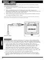
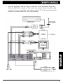
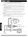
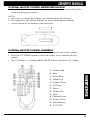
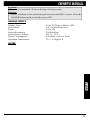
OHM641
6.4” LCD
Color Monitor
OWNER’S MANUAL
INTRODUCTION
The Clarion OHM641 is a full-featured 6.4" LCD Color Monitor. It can be
integrated into a mobile multimedia system. The OHM641 has the following
features:
• 6.4” wide-screen color LCD panel
• A bright, clear screen
• Video input terminal
ABOUT THE MANUAL AND WARRANTY
To start enjoying your new Clarion monitor, please read the instructions listed
in this manual. Keep all instructions for future reference. Please fill out and
send in the enclosed warranty card to protect your purchase and aid in warranty
service. Also, save your original sales receipt as proof of purchase.
TABLE OF CONTENTS
Precautions • • • • • • • • • • • • • • • • • • • • • • • • • • • • • • • • • • • • • • 2
Description • • • • • • • • • • • • • • • • • • • • • • • • • • • • • • • • • • • • • • 3
Package Contents • • • • • • • • • • • • • • • • • • • • • • • • • • • • • • • • • • 3
Button and Connector Locations • • • • • • • • • • • • • • • • • • • • • • • • 3
Wiring Precautions • • • • • • • • • • • • • • • • • • • • • • • • • • • • • • • • • 4
Installation • • • • • • • • • • • • • • • • • • • • • • • • • • • • • • • • • • • • • • 4
Picture Adjustment • • • • • • • • • • • • • • • • • • • • • • • • • • • • • • • • • 5
Applications • • • • • • • • • • • • • • • • • • • • • • • • • • • • • • • • • • • • • 6
Optional Remote Control Battery Installation • • • • • • • • • • • • • • • • 9
Optional Remote Control Operation • • • • • • • • • • • • • • • • • • • • • • 9
Care and Maintenance • • • • • • • • • • • • • • • • • • • • • • • • • • • • • • • 10
Troubleshooting • • • • • • • • • • • • • • • • • • • • • • • • • • • • • • • • • • • 10
Product Specs • • • • • • • • • • • • • • • • • • • • • • • • • • • • • • • • • • • • 11
Notes • • • • • • • • • • • • • • • • • • • • • • • • • • • • • • • • • • • • • • • • • • 11
PRECAUTIONS
1. This set is for use in DC 12V, negative ground vehicles.
2. Do not operate the set in ways other than described in this guide. Doing so
may damage it and may void your warranty.
3. SAFETY FIRST! For rear seat overhead use only. Do not install anywhere
that would permit monitor to be viewed by the driver. Monitor must not be
located in the motor vehicle at any point forward of the back of the front
seats. Monitor must never be used in any manner that will distract driver or
interfere with driver’s safe operation of the motor vehicle.
4. Be careful not to run down the car battery while using the set with the car
stopped.
5. Do not disassemble or modify the set. Doing so may damage it and voids
your warranty.
6. Keep drinks and drops from umbrellas away from the set. Water may
damage the internal circuitry.
2
7. Do not let the set become hot. If temperature in the car is high or the set has
been exposed to direct sunlight and is hot, lower the temperature before
using it. (The liquid crystal panel will work properly within a temperature
range of 30 – 113 degrees F.)
8. In extremely cold temperatures, the movement of the picture may be slow
and the picture may be dark, but this is not a malfunction. The set will work
normally once the temperature increases.
9. Small black and shiny dots inside the liquid crystal panel are normal for
liquid crystal products.
DESCRIPTION
The OHM641 has a TFT active matrix color LCD monitor which delivers a
striking picture and superior image resolution. The OHM641 can be used to
enjoy video images with the Clarion VCP9600 or DVD9600, even if no TV
tuner is connected.
PACKAGE CONTENTS
The OHM 641 comes with the following items:
• 6.4” monitor in fold-down housing
• Mounting gasket
• Mounting bracket
• 3.5mm Male to Male IR extension cable
• Video RCA cable
• Power cable
BUTTON AND CONNECTOR LOCATIONS
1 Remote Sensor
2 Picture Controls
3 IR Remote Sensor Out
4 Power Connector
5 Video In
6 Release Button
3
WIRING PRECAUTIONS
Read all wiring precautions. If you are not sure of the connections, contact
your authorized Clarion dealer.
1. Disconnect the negative (-) lead of the battery before making any power
connections.
2. When creating passage holes for the power wires, use grommets to
eliminate any sharp edges created during drilling. This will protect the wire
from being nicked and causing a short circuit.
3. When connecting the ground lead, fasten the ground lead (black) securely
to a clean metal plate on the vehicle.
NOTE: The OHM641 mointor displays video images only. It does not provide audio output. Refer to the
owner’s manual of the connected device for information on audio output.
INSTALLATION
The OHM641 is an overhead, fold-down 6.4” monitor with an Infrared (IR)
eye. It will accept a video signal from any video source with composite video
out. The IR eye will work directly with the TTX001, VDH9600 and DVD9600.
1. Look over the vehicle for a location for the monitor. Each vehicle is
different and locations will vary. Make sure the monitor will not interfere
with the dome light, wiring, water channels or sunroof operation. The
mounting bracket has slots to accomodate various dome light screw
patterns. In some cases, the vehicle dome light may need to be relocated.
2. Once a location has been determined, run the IR extension, video RCA and
power cables above the head liner to the mounting location.
3. Feed the cables through the hole in the mounting bracket and screw the
bracket to dome light mounting rib. Use short screws so as not to damage
the roof.
4
4. Place the gasket around the housing and plug the cables into the monitor.
Mount the housing to the mounting bracket with the 4 machine screws
provided.
5. You can now run the IR, power and video cables to their respective
destinations. If you’re using the VDH9600 or DVD9600, you can make all
of your connections there.
PICTURE ADJUSTMENT
Brightness
To adjust the picture brightness, use the Brightness UP and DOWN buttons
located on the front panel of the OHM641. Press the UP button to increase the
picture brightness. Press the DOWN button to decrease the picture brightness.
Viewing Angle
To adjust the viewing angle gently tilt the cabinet to the desired posiion. The
recommended viewing angle of the unit is – 30 to +10 degrees vertical and +45
to –45 degrees horizontal.
5
APPLICATIONS
With the VDH9600, TTX001 and the FM100S
1. Pick a location to mount the tuner. Typically the tuner will be located close
to the VCP or DVD player.Avoid areas with excessive heat or moisture and
mount the tuner.
2. Mount the TV antenna (ZCB-303 or equivalent) and plug into the tuner.
3. Plug the 16 pin to A/V out connector into the tuner. Plug the A/V RCA
cables, IR extension and power plug into the 16 pin connector and run to
the video player.
4. Plug the A/V RCA cable into the A/V input of the player. Plug the Y
connector into the player and plug the IR extension into the Y connector.
5. At the OHM641, plug the IR extension and power cables supplied with the
OHM641. Run these cables to the back of the video player. Plug the video
RCA into the video output of the player. Plug the IR extension into the
other leg of the Y connector. Tie all the power wires together. These wires
will be run to the radio location.
6. Plug the audio RCA cable into the audio output of the player and run the
audio RCA and main power cables to the radio location. Remove the radio
and plug the audio RCA into the FM100S audio inputs.
7. Mount the switch for the FM100S and run its power wire to the radio
location. The power and ground wires of the TTX001, video player,
OHM641 and the FM100S can be joined and connected to the radio
accessory and ground wires.
8. Plug the vehicle antenna into the antenna input of the FM100S. Plug the
antenna output of the FM100S into the radio.
9. The FM 100S has a two position switch to select the modulation frequency.
Pick the frequency that has the least amount of radio reception and set that
frequency on the modulator and into a radio preset memory.
Operation
Similar to a home system, the VDH9600 allow their auxiliary A/V inputs to
loop through to their A/V outputs when they are not playing a video tape.
• Because the IR lines have been linked together, each component can be
controlled by its respective remote control when pointed to the IR eye
located on OHM641.
• Turn the vehicle ignition switch to the accessory position. Point the video
player remote at the IR eye and press power to turn on the player. Point the
remote (RC-300) at the IR eye and press power to turn on the tuner.
• You should now see the TV displayed on the monitor.
•
6
•
Turn the modulator and the radio on and tune to the modulated frequency.
Turn the FM100S’s switch on. The audio can now be heard over the sound
system. You can control the video player and the TV tuner by pointing their
respective remotes at the IR eye in the monitor.
7
Stand alone with the TTX001 and the WH100
1. Pick a location to mount the tuner. Avoid areas with excessive heat or
moisture and mount the tuner. Plug the 16 pin to A/V output connector into
the tuner.
2. Mount the TV antenna (ZCB-303 or equivalent) and plug into the tuner.
3. At the OHM641, plug in the video RCA, IR extension and power cables
supplied with the OHM641 and run to the tuner. Plug the video RCA and
IR extension into the tuner.
4. At the WH100 transmitter, plug in the audio RCAs and power connector
and run the cables to the TV tuner. Plug the RCAs into the audio output of
the tuner.
5. Tie all the ground wires to a good ground point. Connect all the power
wires together and run to a fused accessory wire in the vehicle.
Operation
• Point the TV remote (RC-300) at the OHM641 and press power. You should
now see the TV displayed on the monitor and can control the TV tuner
functions with its remote.
• Turn on the headphones with its power switch to listen to the audio.
8
OPTIONAL REMOTE CONTROL BATTERY INSTALLATION
• Insert 2 AAA batteries into the compartment located on the back of the unit,
observing the proper polarity.
NOTES:
• Each time you change the batteries, you must reprogram the channels.
• We suggest you use alkaline batteries; do not use rechargeable batteries.
• Always change all the batteries at the same time.
OPTIONAL REMOTE CONTROL OPERATION
• To use the remote control, press the Power button to turn on the remote.
• Press the TV/VIDEO button to select the source to be controlled by the
remote.
• The VOL(ume) +/- buttons and the MUTE button control the TV volume.
1
2
3
4
5
6
7
8
9
Number Pad
Skip
Erase/Write
Volume Up
Volume Down
TV/Video
Power
Channel Up
Mute
0 Channel Down
q Picture Select
w Auto Memory
e TV/CATV
9
CARE AND MAINTENANCE
Cleaning the cabinet:
• Use a soft, dry cloth to gently wipe off any dirt.
• Do not use benzene, thinner, car cleaner, etc., as these substances may
damage the cabinet or cause the paint to peel.
Cleaning the LCD panel:
• Use a soft, dry cloth to gently wipe off any dust.
• The surface is easily scratched; do not rub it with hard objects.
TROUBLESHOOTING
Before assuming malfunction of the unit, check the following:
Problem:
Power indicator LED is off.
Solution:
• The fuse may be burned out. Replace fuse.
• The wiring is incomplete. Check the wire connections and connect it
properly.
Problem:
The picture has shadows.
Solution:
• The signal condition is poor. This may due to signals reflected off buildings,
mountains, etc. Check again in a different place and direction.
Problem:
The picture has stripes or spots.
Solution:
• There may be interference signals. This may be due to signal interference
from other cars, high voltage lines, neon lights, etc. Check again in another
place.
Problem:
The screen is dark.
Solution:
• The brightness is adjusted too low. Check that the brightness is properly
adjusted and set it properly.
• Usage conditions are poor. This may happen if the temperature in the
vehicle is below 30 degrees F or above 113 degrees F. Check again when
the temperature is between 30 and 113 degrees F.
10
Problem:
The power was turned off when driving on bumpy roads.
Solution:
• Severe vibration to the operation panel activated the DCP’s sensor. Press the
POWER button again to turn the power ON.
PRODUCT SPECS
Display Type:
Screen Size:
Pixels:
Screen Resolution:
Power Source Voltage:
Power Consumption:
Operation Temperature:
Color TFTActive Matrix LCD
6.4” (Actual Panel Size)
320 x 234
224,640 Dots
DC 11 - 15 V
0.8A Max. (0.8A or Less)
30 - 113 degrees F
NOTES
11
661 W. Redondo Beach Blvd.
Gardena, CA 90247
1-800-GO-CLARION
www.clarion-usa.com
OHM641-10 Rev.3 (03/00)