1
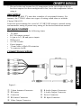
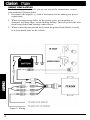
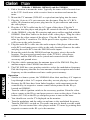
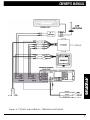
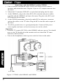
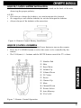
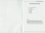
TTX001
TV TUNER
OWNER’S MANUAL
INTRODUCTION
The Clarion TTX001 is a TV Tuner. It can be integrated into a mobile
multimedia system. It has a number of features, including:
• Two types of wiring permitted - stand alone or with VMA1131
• Quick tuning to your desired stations
• Stereo broadcast reception
• Video/audio (stereo) output jacks
• Display function when using audio
ABOUT THE MANUAL AND WARRANTY
To start enjoying your new Clarion TTX001 TV Tuner, please read the
instructions listed in this manual. Keep all instructions for future reference.
Please fill out and send in the enclosed warranty card to protect your purchase
and aid in warranty service. Also, save your original sales receipt as proof of
purchase.
TABLE OF CONTENTS
Precautions • • • • • • • • • • • • • • • • • • • • • • • • • • • • • • • • • • • • •2
Description • • • • • • • • • • • • • • • • • • • • • • • • • • • • • • • • • • • • •3
Package Contents • • • • • • • • • • • • • • • • • • • • • • • • • • • • • • • • •3
Connector Locations • • • • • • • • • • • • • • • • • • • • • • • • • • • • • • •3
Wiring Precautions • • • • • • • • • • • • • • • • • • • • • • • • • • • • • • • •4
Applications • • • • • • • • • • • • • • • • • • • • • • • • • • • • • • • • • • • •5
Using the Remote Control • • • • • • • • • • • • • • • • • • • • • • • • • • • •9
Troubleshooting • • • • • • • • • • • • • • • • • • • • • • • • • • • • • • • • •10
Product Specs • • • • • • • • • • • • • • • • • • • • • • • • • • • • • • • • • • •11
Notes • • • • • • • • • • • • • • • • • • • • • • • • • • • • • • • • • • • • • • • •11
PRECAUTIONS
1. This unit is for use in DC 12V, negative ground vehicles.
2. Do not operate the unit in ways other than described in this guide. Doing so
may damage it and may void your warranty.
3. SAFETY FIRST! For rear seat use only. Do not install monitors displaying
video information anywhere that would permit viewing by the driver.
Monitors must not be located in the motor vehicle at any point forward of
the back of the front seats. Monitors must never be used in any manner that
will distract driver or interfere with driver’s safe operation of the motor
vehicle.
4. Be careful not to run down the car battery while using the unit with the car
stopped.
5. Do not disassemble or modify the unit. Doing so may damage it and voids
your warranty.
6. Keep drinks and drops from umbrellas away from the unit. Water may
damage the internal circuitry.
2
7. Do not let the unit become hot. If temperature in the car is high or the set
has been exposed to direct sunlight and is hot, lower the temperature before
using it.
DESCRIPTION
The Clarion TTX001 TV tuner has a number of exceptional features. For
instance, the TTX001 allows two types of wiring: stand alone or with the
Clarion VMA1131.
It also has preset tuning (for a total of 12 VHF/UHF stations), manual tuning
and automatic tuning to permit easy tuning of the desired broadcast stations.
PACKAGE CONTENTS
The TTX001 comes with the following items:
• TV tuner
• RC-300 remote control
• 16 pin to A/V, IR and power inputs
• IR Receiver
• A/V RCAcable
• Power harness
• 3.5mm Male to Male IR extension
• Y connector for IR
CONNECTOR LOCATIONS
Figure 1-
1
2
3
4
5
3.5mm Antenna Connector
IR Sensor
Connector
IR Sensor Connector
Video Output Connector
6
7
8
9
R Audio Output Connector
L Audio Output Connector
Power Connector
IR Input Connector
3
WIRING PRECAUTIONS
Read all wiring precautions. If you are not sure of the connections, contact
your authorized Clarion dealer.
1. Disconnect the negative (-) lead of the battery before making any power
connections.
2. When creating passage holes for the power wires, use grommets to
eliminate any sharp edges created during drilling. This will protect the wire
from being nicked and causing a short circuit.
3. When connecting the ground lead, fasten the ground lead (black) securely
to a clean metal plate on the vehicle.
Figure 2- Wiring
4
APPLICATIONS
The TTX001 can be operated in a number of applications. Find yours below.
With the VMA1131
1. Place tuner into the channel on the back of the monitor and slide the tab
into the slot. Mount tuner with the two machine screws supplied.
2. Plug the 16 to 16 pin cable (supplied with the monitor) into the tuner and
the back of the monitor.
3. Mount the antenna (ZCB-003 or equivalent) and plug into the antenna input
of the tuner.
4. Plug the power connector into the monitor and connect to vehicle accessory
and ground.
Operation
• The tuner can be controlled by the buttons on the monitor or by the remote
control.
Figure 3- TTX001 with VMA1131
5
With the VDH9600, OHM641 and the FM100S
1. Pick a location to mount the tuner. Typically the tuner will be located close
to the VCP. Avoid areas with excessive heat or moisture and mount the
tuner.
2. Mount the TV antenna (ZCB-003 or equivalent) and plug into the tuner.
3. Plug the 16 pin to A/V out connector into the tuner. Plug the A/V RCA
cables, IR extension and power plug into the 16 pin connector and run to
the video player.
4. Plug the A/V RCA cable into the A/V input of the player. Plug the Y
connector into the player and plug the IR extension into the Y connector.
5. At the OHM641, plug the IR extension and power cables supplied with the
OHM641. Run these cables to the back of the video player. Plug the video
RCA into the video output of the player. Plug the IR extension into the
other leg of the Y connector. Tie all the power wires together. These wires
will be run to the radio location.
6. Plug the audio RCA cable into the audio output of the player and run the
audio RCA and main power cables to the radio location. Remove the radio
and plug the audio RCA into the FM100S audio inputs.
7. Mount the switch for the FM100S and run its power wire to the radio
location. The power and ground wires of the TTX001, video player,
OHM641 and the FM100S can be joined and connected to the radio
accessory and ground wires.
8. Plug the vehicle antenna into the antenna input of the FM100S. Plug the
antenna output of the FM100S into the radio.
9. The FM 100S has a two position switch to select the modulation frequency.
Pick the frequency that has the least amount of radio reception and set that
frequency on the modulator and into a radio preset memory.
Operation
Similar to a home system, the VDH9600 allow their auxiliary A/V inputs to
loop through to their A/V outputs when they are not playing a video tape.
• Because the IR lines have been linked together, each component can be
controlled by its respective remote control when pointed to the IR eye
located on OHM641.
• Turn the vehicle ignition switch to the accessory position. Point the video
player remote at the IR eye and press power to turn on the player. Point the
remote (RC-300) at the IR eye and press power to turn on the tuner.
• You should now see the TV displayed on the monitor.
• Turn the modulator and the radio on and tune to the modulated frequency.
Turn the FM100S’s switch on. The audio can now be heard over the sound
system. You can control the video player and the TV tuner by pointing their
respective remotes at the IR eye in the monitor.
•
6
Figure 4- TTX001 with OHM641, VDH9600 and FM100S
7
Stand alone with the OHM641 and the WH100
1. Pick a location to mount the tuner. Avoid areas with excessive heat or
moisture and mount the tuner. Plug the 16 pin to A/V output connector into
the tuner.
2. Mount the TV antenna (ZCB-003 or equivalent) and plug into the tuner.
3. At the OHM641, plug in the video RCA, IR extension and power cables
supplied with the OHM641 and run to the tuner. Plug the video RCA and
IR extension into the tuner.
4. At the WH100 transmitter, plug in the audio RCAs and power connector
and run the cables to the TV tuner. Plug the RCAs into the audio output of
the tuner.
5. Tie all the ground wires to a good ground point. Connect all the power
wires together and run to a fused accessory wire in the vehicle.
Operation
• Point the TV remote (RC-300) at the OHM641 and press power. You should
now see the TV displayed on the monitor and can control the TV tuner
functions with its remote.
• Turn on the headphones with its power switch to listen to the audio.
Figure 5- TTX001 with OHM641 and WH200
8
REMOTE CONTROL BATTERY INSTALLATION
• Insert 2 AAAbatteries into the compartment located on the back of the unit,
observing the proper polarity.
NOTES:
• Each time you change the batteries, you must reprogram the channels.
• We suggest you use alkaline batteries; do not use rechargeable batteries.
• Always change all the batteries at the same time.
Figure 6- Remote Control Battery Installation
REMOTE CONTROL OPERATION
• To use the remote control, press the Power button to turn on the remote.
• Press the TV/VIDEO button to select the source to be controlled by the
remote.
• The VOL(ume) +/- buttons and the MUTE button control the TV volume.
1
2
3
4
5
6
7
8
9
Number Pad
Skip
Erase/Write
Volume Up
Volume Down
TV/Video
Power
Channel Up
Mute
0 Channel Down
q Picture Select
w Auto Memory
e TV/CATV
Figure 7- Remote Control Operation
9
TROUBLESHOOTING
Before assuming malfunction of the unit, check the following:
Problem:
No power.
Solution:
• The fuse may be burned out. Replace the fuse with one of the same rating.
• The wiring is incomplete. Check the wire connections and connect them
properly.
Problem:
The picture is unclear.
Solution:
• The reception condition is poor. This may due to an insufficient signal
arriving due to being in the shadow of mountains or buildings. Check again
in a location exposed to a stronger signal.
Problem:
The picture is double or triple.
Solution:
• There is an interfering broadcast. The signal might be reflected from
mountains or buildings. Check by changing location or direction.
Problem:
The picture has a flecked or lined pattern.
Solution:
• There may be effects from cars, trains, neon signs, or other interfering
signals. Check by changing location.
Problem:
No sound.
Solution:
• (Only for FM modulator wiring) Check that the frequency of the vehicle
stereo is matched (88.3 MHz or 88.7 KHz).
Problem:
A control does not function.
Solution:
• Incorrect setting of the position switch. Check whether the setting matches
the details of the wiring.
10
PRODUCT SPECS
Power Source Voltage:
Power Consumption:
Operation Temperature:
DC 11-15V
1.5Amax. (1.5Aor less)
30 - 113 degrees F
NOTES
11
661 W. Redondo Beach Blvd.
Gardena, CA 90247
1-800-GO-CLARION
www.clarion-usa.com
TTX001-10 Rev.2 (03/00)