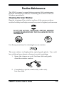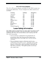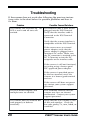
1
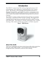
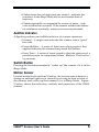
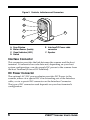
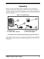
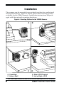
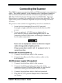
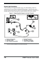
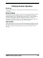
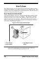
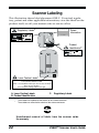
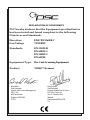
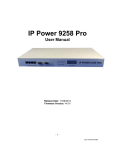
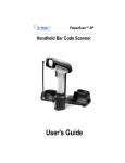
VS800
Scanner
User's Guide
PSC Scanning, Inc.
959 Terry Street
Eugene, Oregon 97402-9120
Telephone: (541) 683-5700
Telefax: (541) 345-7140
www.pscnet.com
PSC and the PSC logo are registered trademarks of PSC INC. VS800 is a trademark owned by PSC INC.
All rights reserved. No part of the contents of this documentation or the procedures
described therein may be reproduced or transmitted in any form or by any means without
prior written permission of PSC Inc. Owner of PSC Inc.'s products are hereby granted nonexclusive, revocable license to reproduce and transmit this documentation for the purchaser's
own internal business purposes. Purchaser shall not remove or alter any proprietary notices,
including copyright notices, contained on this documentation and shall ensure that all
notices appear on any reproductions of the documentation.
Disclaimer
Reasonable measures have been taken to ensure that all information contained in this manual is complete and accurate. However, PSC reserves the
right to change any specification at any time without prior notice.
Table of Contents
Introduction ....................................................................................................... 3
About this Guide ....................................................................................... 3
Operational Modes ........................................................................................... 4
Selftest Mode ............................................................................................ 4
Operational Mode ..................................................................................... 4
Sleep Mode .............................................................................................. 4
Controls and Indicators ..................................................................................... 4
Visual Indicator ......................................................................................... 4
Audible Indicator ....................................................................................... 5
Switch Button ............................................................................................ 5
Motion Sensor .......................................................................................... 5
Interface Connector .................................................................................. 6
DC Power Connector ................................................................................ 6
Unpacking ........................................................................................................ 7
Installation ........................................................................................................ 8
Connecting the Scanner ................................................................................... 9
Power-Off-Terminal (P.O.T.) ...................................................................... 9
AC/DC power supply (if required) ............................................................. 9
Power-Up Procedure .............................................................................. 10
Verifying Scanner Operation ........................................................................... 11
Power-up ................................................................................................ 11
Passes Selftest ....................................................................................... 11
Fails Selftest ........................................................................................... 11
How To Scan .................................................................................................. 12
Scan Volume and Scan Depth ................................................................ 12
Sweep Scanning ..................................................................................... 13
Presentation Scanning ............................................................................ 13
Customizing Your Scanner's Operation ........................................................... 14
Changing The Volume ............................................................................. 14
Other Programmable Features ............................................................... 15
Routine Maintenance ...................................................................................... 17
Cleaning the Scan Window ..................................................................... 17
Specifications ................................................................................................. 18
Physical Specifications ........................................................................... 18
Environmental Specifications .................................................................. 18
Electrical Specifications .......................................................................... 18
Laser Safety Information ................................................................................. 19
Troubleshooting .............................................................................................. 20
Regulatory Agency Information ...................................................................... 21
FCC Statements ..................................................................................... 21
Scanner Labeling .................................................................................... 22
Standard Warranty .......................................................................................... 23
VS800™ Scanner User's Guide
1
2
VS800™ Scanner User's Guide
Introduction
The VS800™ scanner from PSC® delivers high performance, fullfunctioned bar code scanning in a small housing to save counter
space. The product, with its rugged industrialized enclosure, is
designed for durability, prolonged life, and low maintenance costs.
With the multiple mounting options, operators can adjust the scanner to create a convenient, comfortable, and productive work environment.
The VS800™ scanner's design minimizes the need for user training
and accepts "presentation" and "sweep" scanning. The aggressive,
omnidirectional scan pattern minimizes the need to adjust or orient
individual items. The scanner is virtually maintenance free. Periodic
cleaning of the scanner and the scan window is all that's required.
Figure 1. VS800 Scanner
About this Guide
This User's Guide provides basic instructions on the setup, operation,
and care of the VS800 scanner. It is assumed that the user has a
background and a familiarity with bar code scanning.
VS800™ Scanner User's Guide
3
Operational Modes
The VS800 scanner has three operational modes:
Selftest Mode
The VS800 scanner automatically performs a Selftest on initial
power-up. The Selftest checks the functionality of the internal
circuits. If no problem is found, the scanner displays a single bright
flash of the LED light, and sounds four beeps. It then transitions into
the Operational Mode. Other tones indicate if a problem was
detected – see the Troubleshooting section for details on possible
causes and solutions.
Operational Mode
This is the scanner's normal operating mode. In this mode the
scanner is ready to read bar code labels and transmit data to the host
POS Terminal.
Sleep Mode
After a prolonged period of inactivity, the laser and the motor turn
off to save power and prolong component life. Pressing the switch or
passing an object in front of the scanner, causes the scanner to "wakeup." The laser and motor timeout periods are programmable using
the special bar code labels found in the PSC Duet/VS800 Programming
Guide (Part Number R44-1740).
Controls and Indicators
Visual Indicator
The Light Emitting Diode (LED) provides a visual indicator of the
various system operations (reference Figure 2):
• On Dim – scanner is operational and ready to scan.
• Flashes once brightly after reading a bar code – indicates a
"good" scan. Usually accompanied by a single tone from the
speaker.
4
VS800™ Scanner User's Guide
• Flashes from dim to bright once per second – indicates the
scanner is in the Sleep Mode due to an extended time of
inactivity.
• Flashes repeatedly accompanied by a series of tones – indicates a failure has occurred. If the scanner exhibits this behavior or behaves erratically, contact your service personnel.
Audible Indicator
A Speaker produces an audible indicator of scanner operation:
• Normal – A single tone indicates the scanner read a "good"
bar code.
• Passed Selftest – A series of four tones when power is first
applied indicates the scanner has passed the Selftest.
• Error Tone – A series of tones sound to alert the operator of a
possible system or component failure. (Refer to Troubleshooting section).
Switch Button
Pressing the Switch momentarily "wakes up" the scanner if it is in the
Sleep Mode.
Motion Sensor
Located inside the Front Scan Window, the motion sensor detects a
change in ambient light levels caused by moving an item in front of
the scanner, and wakes up the scanner if it is in Sleep Mode. Figure
2, below, shows the indicators, controls, and connectors of the VS800
scanner.
VS800™ Scanner User's Guide
5
Figure 2. Controls, Indicators and Connectors
A
B
C
E
D
F
A.
B.
C.
D.
Scan Window
Motion Sensor (Inside)
Visual Indicator (LED)
Switch
E. Interface/DC Power cable
connector
F. Speaker
Interface Connector
This connector provides the link between the scanner and the host
terminal. It transmits bar code data and, depending on your host
system configuration, can also supply DC power to the scanner from
the host Terminal (Power-Off-Terminal).
DC Power Connector
The optional AC/DC power adapter provides DC Power to the
scanner, either via a special DC wire extending out of the Interface
cable, or via a special DC connector on the Interface Connector.
The type of DC connector used depends on your host terminal's
configuration.
6
VS800™ Scanner User's Guide
Unpacking
Before you open the VS800 scanner shipping carton, inspect the
exterior of the carton for damage. If the carton is torn or crushed,
carefully open and inspect the contents to ensure that no damage has
occurred. Notify your carrier immediately if you think that there has
been any damage.
Figure 3. Package Contents
C
A
B
D
A. VS800 Scanner
B. Interface Cable1 (Optional)
1
C. User's Guide (This manual)
D. AC/DC Power Adapter1
Your hardware may vary from illustration based on your POS Terminal.
If anything is missing or the wrong interface cable has been included
with your scanner, contact your dealer/distributor or call your local
PSC office.
VS800™ Scanner User's Guide
7
Installation
The scanner can be mounted in an optimal position for comfort and
increased efficiency. Figure 4, below, shows the mounting options
available for the VS800 scanner. Installation instructions are packaged with the optional mounting hardware.
Figure 4. Mounting Options for the VS8000 Scanner
A. Countertop
C. Under a Shelf
A
B
C
D
B. Side of POS Terminal
D. Left or Right of POS
Your VS800 support hardware may differ from the illustration depending on your POS environment.
8
VS800™ Scanner User's Guide
Connecting the Scanner
The VS800 scanner connects to the host POS terminal via an interface
cable. The cable connects to the scanner with a modular connector
and to the host terminal with the connector required by the host
(RS-232, OCIA, Keyboard Wedge, Wand or IBM POS). Figure 5
shows how to connect the scanner to the store host terminal. The
type of DC power connector depends on your existing store host
terminal.
DC power to the scanner is supplied by one of two methods:
1.
From the host terminal (Power-Off-Terminal)
through a single cable that carries both data and DC
power.
2.
From an optional AC/DC power adapter that
provides DC power, either through the side of the
connector to the POS System, or through a branch in
the Y-cable connection.
Never work on equipment, connect or disconnect signal
cables during periods of lighting activity.
Always power-down (switch off) all equipment prior to
connecting cables.
Power-Off-Terminal (P.O.T.)
1.
Connect the interface cable to the scanner.
2.
Connect the other end of the interface cable to the
host terminal.
AC/DC power supply (if required)
1.
Connect the interface cable to the scanner.
2.
Connect the DC barrel plug into the side of the
connector at the POS end of the cable, or into the DC
connector of the power branch of the Y-cable.
3.
Connect the interface cable to the host terminal.
4.
Plug the AC/DC power adapter into a functional
AC outlet.
VS800™ Scanner User's Guide
9
Power-Up Procedure
The system power-up procedure may vary depending on the requirements of your Point-of-Sale (POS) system. Check with your
system supervisor and/or refer to the terminal operator's manual for
proper power-down and power-up procedures for your system.
Figure 5. Connecting the Scanner to the Host Terminal
a. Interface Connector
b. Interface Cable
c. Host Terminal Connector1
1
10
d. To Host Terminal
e. DC Power Connector
f. AC/DC Power Adapter
Your Host Terminal Connector may vary from the illustration.
VS800™ Scanner User's Guide
Verifying Scanner Operation
Power-up
Power-up the system. The scanner will automatically run a PowerUp Selftest.
Passes Selftest
The scanner should emit four successive tones indicating that it has
passed the Power-Up Selftest routine. The LED indicator lamp
flashes brightly once. The LED then transitions to a dim condition,
(or Off if so programmed) indicating the scanner is ready for
operation. Scan a few items to verify that data is properly communicated between the scanner and your POS terminal.
Fails Selftest
If the scanner powers-up, but the LED lamp begins flashing and the
speaker repeats a series of error tones, or the scanner does not read
bar codes, or behaves erratically, go to the section titled Troubleshooting.
VS800™ Scanner User's Guide
11
How To Scan
The VS800 is ready to scan a bar code when the LED light is on dim1
(Operational Mode) or the LED is flashing slowly (Sleep Mode). The
scanner's specially designed scan pattern minimizes the need for the
operator to orient the item for scanning.
Scan Volume and Scan Depth
As shown in Figure 6, the scan volume extends approximately eight
inches (20 cm) in front of the scan window. The optimal scanning
distance is at the center of the scan volume, or approximately four
inches (10 cm) from the window. The scanner can read bar codes
either in the sweep or presentation mode to accommodate different
user styles. (See Figures 7 and 8).
Figure 6. Scan Volume and Scan Depth
b
a
c
a. Scan Window
b. Scan Volume
1.
12
c. Scan Depth (8 inches
20 cm)
Unless the LED is programmed to the Off condition by using special programming
labels found in the Duet/VS800 Programming Guide (R44-1740).
VS800™ Scanner User's Guide
Sweep Scanning
To perform a sweep scan, move (sweep) the product, with the bar
code facing the front window, laterally through the scan volume.
Figure 7. Sweep Scanning
2HD
2HD
Presentation Scanning
For optimum scanning performance, face the bar code towards the
center of the front scanner window. Move the product with the bar
code towards the scanner, as shown in Figure 8.
Figure 8. Presentation Scanning
2HD
VS800™ Scanner User's Guide
13
Customizing Your Scanner's Operation
Customizing or programming a scanner provides maximum flexibility and allows a single scanner to serve many installation environments. Since the VS800 scanner supports a variety of interfaces,
configurations and bar code symbologies, it may be necessary to
customize your scanner to meet the specific requirements of your
retail environment. Customizing the scanner is done by scanning
special bar codes which change the way the scanner operates.
If the scanner does not read bar codes and/or transmit data the way
you need it to, contact your dealer or distributor for more programming options.
Changing The Volume
There are three possible volume settings. Each time you scan the bar
code below, the scanner’s volume changes to the next higher level. If
the current volume is the highest selection, the volume changes to
the lowest setting. If the scanner is powered off or reset, this setting
returns to the factory default and will need to be set again to your
desired setting. For permanent volume change, see the
Duet/VS800 Scanner Programming Guide, (P/N: R44-1740).
Increment Volume
14
VS800™ Scanner User's Guide
Other Programmable Features
The table below shows some of the major features that may be
changed using the Duet/VS800 Scanner Programming Guide.
Symbology Activation/Deactivation
UPC/EAN/JAN:
– UPC-A and UPC-E
Add ons
– EAN-8 and EAN-13
– UPC P2 and UPC P5
– Jan-8 and JAN -13
– Code 128
– UPC-A with EDGE™ stitching1
Industrial Codes:
– Interleaved 2 of 5
– Code 128
– Code 39 (variable length)
– Codabar
– Code 39 (fixed length label stitching)
– MSI/Plessey
Other Features:
– two label read
– Autodiscriminate UPC EDGE™ with Add-ons and 5
Industrial codes.
Communication Interface Activation/Deactivation
Single Interfaces:
– Wand Emulation
– RS-232
– Keyboard Wedge
– OCIA
– IBM 46xx
Dual Interfaces:
– RS-232 and IBM 46xx
– RS-232 and OCIA
– RS-232 and Keyboard-Wedge
Triple Interfaces:
– RS-232, IBM 46xx, and Keyboard-Wedge
1.
This optional feature is not available on all models. Contact your PSC dealer or
distributor for more information.
VS800™ Scanner User's Guide
15
Programmable Scanner Features
User Indicators Parameters:
– Speaker Volume Selection
– Speaker Tone Pitch
– Speaker Tone Length
Sleep Mode:
– Motor Timeout
– Laser Timeout
Other programmable features include
– Supplemental labels
– Two label configuration
– Label ID prefixes
– Coupon Processing
Contact PSC for more information on these programmable features.
16
VS800™ Scanner User's Guide
Routine Maintenance
The VS800 scanner's rugged design requires little maintenance.
Routine maintenance consists of cleaning the scanner and Scan
Window periodically.
Cleaning the Scan Window
Regular cleaning of the window surface of the scanner reduces
residue buildup and helps ensure the system’s highest performance.
WARNING
DO NOT USE ALCOHOL, PETROLEUM, ACETONE, ABRASIVE
CLEANER OR ABRASIVE PADS. THEY WILL HARM OR SCRATCH
THE SURFACE.
ALCOHOL
or
ACETONE
ABRASIVES
Use these procedures for cleaning the scan window.
NOTE
The scan window is a high quality, optical grade plastic. Use a soft
lens cloth and non-abrasive cleaner to avoid scratching.
1.
Spray the cleaner on a soft, lint-free cloth and gently
clean the window surface.
ss
Gla ner
a
Cle
2.
Completely wipe the window dry with a soft,
lint-free cloth.
VS800™ Scanner User's Guide
17
Specifications
Physical Specifications
Scanner
AC/DC Power Adapter
Height = 5.90" (15.0 cm)
Width = 3.50" (8.9 cm)
Depth = 3.00" (7.6 cm)
Weight = 12.0 oz. (311g)
Height = 2.80" (7.0 cm)
Width = 2.10" (5.3 cm)
Depth = 2.75" (7.0 cm)
Weight = 10.0 oz. (290g)
Environmental Specifications
Operating
Storage
Temperature
00 C to + 400 C
320 F to 1040 F
-400C to + 700 C
-400 F to 1580 F
Humidity
5-95 % (non condensing)
5-95% (non-condensing)
Ambient Light
200 foot candles Maximum (2153 Lux )
Electrical Specifications
Scanner Input Power Specifications
Operational voltage
DC Power Consumption
Input Voltage Ripple
4.7 to 14 volts
3.00 watts max. (single interface)
500mV DC Maximum
External AC to DC Power Adapters
Output:
12 VDC @ 600 mA
Power-Off-Terminal
If the host terminal supplies the power, the host must provide power
compatible with the Input Power Specification. For example, a 12V
system must provide at least 250 mA (3 Watts).
WARNING
Use only AC/DC Power Adapters approved by PSC for the VS800
scanner. Use of other power adapters may cause damage to the
product which is not covered by the factory warranty.
NOTE: Specifications subject to change without notice.
18
VS800™ Scanner User's Guide
AC to DC Power Adapters
The AC to DC power adapters available for the VS800 scanner are
listed in the table below. Power Adapters for other countries are
available.
Country
Voltage
Frequency
Australia
Canada
France
Germany
Italy
United States
Japan
Mexico
Scandinavia
Spain
United Kingdom
240
120
220
220
220
120
100
120
220
220
240
50 HZ
60 HZ
50 HZ
50 HZ
50 HZ
60 HZ
50 HZ
60 HZ
50 HZ
50 HZ
50 HZ
Laser Safety Information
The VS800 scanner requirements for laser safety are based on IEC
Standard Publication 825-1:1993 and EN60825-1:1996 (Europe),
CDRH 21CFR, Part 1040 (United States and Canada), and AS
2211:1997 (Australia).
• Use of controls or adjustments or performance of
procedures other than those specified herein may
result in hazardous laser light, and void the factory
warranty.
• Do not attempt to open or otherwise service any
component in the optics cavity. Opening or servicing
any part of the optics cavity by unauthorized personnel may violate laser safety regulation, and will void
the factory warranty. The optics system is a factoryonly repair item.
VS800™ Scanner User's Guide
19
Troubleshooting
If the scanner does not work after following the previous instructions, refer to the chart below for possible problems and how to
fix them.
Problem
The scanner fails to power-up. The
LED is not lit and no tones are
emitted.
Possible Causes/Solutions
The interface cable is loose or not
plugged into the POS Terminal.
Verify that the interface cable is
connected to the POS Terminal
Connector.
Verify that the scanner interface is
compatible with the POS Terminal.
If the scanner uses an external
power adapter, verify that the
power adapter is plugged into a
functional AC outlet. Make sure
the DC connector is attached to the
DC Y-Conector, or into the DC
receptacle on the interface cable.
If the scanner is still not functional,
try testing using a known good
PSC approved power adapter.
If the scanner is provided power
by the host terminal, move the
scanner to a known good terminal
and test.
If the scanner still does not power
up, contact your system support
personnel.
The LED flashes brightly, and
multiple tones are emitted.
This condition indicates that the
scanner may have an internal
malfunction. Contact your system
support personnel.
The scanner does not read the bar
code properly or behaves
erratically.
Verify that the scan window is free
of dirt and smudges. Check the
bar code quality, i.e., torn, faded, or
wrinkled.
20
VS800™ Scanner User's Guide
Regulatory Agency Information
FCC Statements
This device complies with Part 15 of the FCC rules and the Radio
Interference Regulation of the Canadian Department of Communications for a Class A computing device. Operation is subject to the
following two conditions:
1.
This device may not cause harmful interference.
2.
This device must accept any interference received
including interference that may cause undesired
operation.
This equipment has been tested and found compliant with the limits
for a Class A digital device, pursuant to Part 15 of the FCC rules.
These limits are designed to provide reasonable protection against
harmful interference when the equipment is operated in a commercial environment. This equipment generates, uses and can radiate
radio frequency energy and, if not installed and used in accordance
with the instruction manual, may cause harmful interference to radio
communications. Operation of this equipment in a residential area is
likely to cause harmful interference, in which case the user will be
required to correct the interference at his or her own expense.
The electrical socket for this product must be located near the
scanner and be readily accessible to the operator.
•This Class A digital apparatus meets all requirements of
the Canadian Interference-Causing Equipment Regulations.
•Cet appareil numerique de la classe A respecte toutes les
exigences du Reglement sur le material broilleur du
Canada.
VS800™ Scanner User's Guide
21
Scanner Labeling
This illustration shows label placement ONLY. For actual regulatory, patent and other applicable information, view the labels on the
product itself, or call your nearest sales or service office.
Covered by one or more
of the following Patents:
Regulatory Labels2
Patent
Information
4.7 - 14 VDC
Product
Identification2
Laser Caution Labels1
Complies with 21 CFR 1040 and part 15 of FCC Rules. Class
1 laser product, IEC 825-1:1993.
Caution - Laser Radiation when open. Do not stare into beam.
Class IIa Laser Product.
Avoid long term viewing of direct laser light.
A. Laser Caution Labels
B. Product Identification
1.
2.
C. Regulatory Labels
These labels are molded into the exterior of the scanner enclosure.
These labels are affixed to the exterior of the scanner enclosure.
WARNING
Unauthorized removal of labels from the scanner voids
the warranty.
22
VS800™ Scanner User's Guide
Standard Warranty
PSC warrants to Customer that PSC's products will be free from defects in materials and workmanship
for a period of one year from product shipment.
In order to obtain service under this Warranty, Customer must notify PSC of the claimed defect before
the expiration of the Warranty period and obtain from PSC a return authorization number for return of the
product to designated PSC service center. If PSC determines Customer’s claim is valid, PSC will repair
or replace product without additional charge for parts and labor. Customer shall be responsible for
packaging and shipping the product to the designated PSC service center, with shipping charges
prepaid. PSC shall pay for the return of the product to Customer if the shipment is to a location within
the country in which the PSC service center is located. Customer shall be responsible for paying all
shipping charges, duties, taxes, and any other charges for products returned to any other locations.
Warranty is subject to the limitations and exclusions set forth below. Warranty set forth above is in lieu of
any other warranties, expressed or implied, including merchantability and fitness.
Exclusions
Warranty coverage shall not apply to any claimed defect, failure or damage which PSC determines was
caused by: improper use of product; tampering or unauthorized repair attempts; failure to provide product
maintenance, including but not limited to cleaning of the scan window(s) in accordance with product
manual; installation or service of product by other than PSC representatives; use of product with any
other instrument, equipment or apparatus; modification or alteration of product. External cables and
replacement of scan windows due to scratching, stains or other degradation will not be covered under
the Warranty. Products returned for service must be accompanied by the original external power
supplies for performance of service.
Limitations of Liability
PSC repair or replacement of defective product as set forth above is the customer's sole and exclusive
remedy on account of claims of breach of warranty or product defect. Under no circumstances will PSC
be liable to customer or any third party for any lost profits, or any incidental, consequential indirect,
special or contingent damages regardless of whether PSC had advance notice of the possibility of such
damages.
Assignment
Customer may not assign or otherwise transfer its rights or obligations under Warranty except to a
purchaser or transferee of product. No attempted assignment or transfer in violation of this provision
shall be valid or binding upon PSC.
Risk of Loss
Customer shall bear risk of loss or damage for product in transit to PSC. PSC shall assume risk of loss
or damage for product in PSC’s possession or product being returned to Customer by PSC, except such
loss or damage as may be caused by the negligence of Customer, its agents or employees. In the
absence of specific written instructions for the return of product to Customer, PSC will select the carrier,
but PSC shall not thereby assume any liability in connection with the return shipment.
VS800™ Scanner User's Guide
23
NOTES
24
VS800™ Scanner User's Guide
DECLARATION OF CONFORMITY
PSC hereby declares that the Equipment specified below
has been tested and found compliant to the following
Directives and Standards:
Directives:
Low Voltage
EMC 89/336/EEC
73/23/EEC
Standards:
EN 55022-B
EN 60825-1
EN 50082-1
EN 60950
Equipment Type:
Bar Code Scanning Equipment
Product:
VS800™ Scanner
Brad West
Vice President
Quality and Process Management
PSC, Inc.
959 Terry Street
Eugene, OR 97402
U.S.A.
Peter Lomax
Vice President
Europe, Middle East & Africa
PSC Bar Code Ltd.
Axis 3, Rhodes Way
Watford
Hertfordshire WD24 4TR
UK
Asia Pacific
PSC Hong Kong
Hong Kong
Telephone: [852]-2-584-6210
Fax: [852]-2-521-0291
Italy
PSC S.p.A.
Vimercate (MI), Italy
Telephone: [39] (0) 39/62903.1
Fax: [39] (0) 39/6859496
Australia
PSC Asia Pacific Pty Ltd.
North Ryde, Australia
Telephone: [61] 0 (2) 9878 8999
Fax: [61] 0 (2) 9878 8688
Japan
PSC Japan K.K.
Shinagawa-ku, Tokyo, Japan
Telephone: 81 (0)3 3491 6761
Fax: 81 (0)3 3491 6656
France
PSC S.A.R.L.
LES ULIS Cedex, France
Telephone: [33].01.64.86.71.00
Fax: [33].01.64 46.72.44
Latin America
PSC S.A., INC.
Miami, Florida, USA
Telephone: (305) 539-0111
Fax: (305) 539-0206
Germany
PSC GmbH
Darmstadt, Germany
Telephone: 49 (0) 61 51/93 58-0
Fax: 49 (0) 61 51/93 58 58
United Kingdom
PSC Bar Code Ltd.
Watford, England
Telephone: 44 (0) 1923 809500
Fax: 44 (0) 1923 809 505
www.pscnet.com
PSC Inc.
959 Terry Street
Eugene, OR
Telephone: (541) 683-5700
Fax: (541) 345-7140
©2004 PSC INC.
R44-2000 (Rev.D)
03/04