1
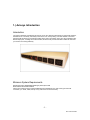
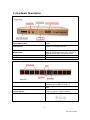
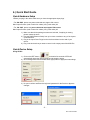
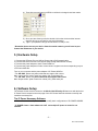
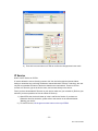
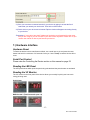
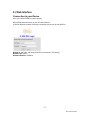
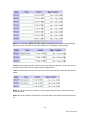
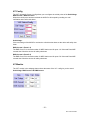
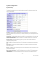
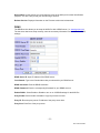
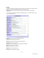
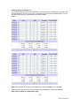
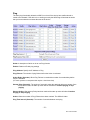
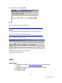
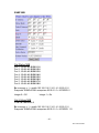
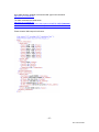
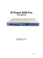
IP Power 9258 Pro
User Manual
Release Date: 11/06/2012
Firmware Version: V4.01
-1–
Ref: P9258Y90M02
Warning: Any changes made to this equipment without permission may cause damages to the
device!
IMPORTANT NOTICE
1. IP Power 9258 Pro was designed for indoor use, we carry no responsibility for possible damages caused
by outdoor use, especially in the rain.
2. Please use the power adapter provided by the dealer, we carry no responsibility for the possible damage
from using power adapters not .
4. Do not shake the IP Power 9258 Pro in any fashion
5. Please contact the dealer If IP Power 9258 Pro is not working properly.
Copyright © 2011 All rights reserved. No part of this publication may be reproduced, stored in a retrieval
system, or transmitted in any form or by any means, electronic, mechanical, photocopying, recording or
otherwise, without the prior written consent of us.
All trademarks and products mentioned in this document are the properties of us.
-2–
Ref: P9258Y90M02
Table of Content
1.) AVIOSYS INTRODUCTION ............................................................................ 5
Introduction .................................................................................................................................................. 5
Minimum System Requirements ................................................................................................................. 5
2.) PRODUCT OVERVIEW ................................................................................... 6
Features ......................................................................................................................................................... 6
Specification .................................................................................................................................................. 6
Package Contents ......................................................................................................................................... 6
3.) HARDWARE DESCRIPTION .......................................................................... 7
4.) QUICK START GUIDE .................................................................................... 8
Quick Hardware Setup ................................................................................................................................ 8
Quick Device Setup....................................................................................................................................... 8
5.) HARDWARE SETUP ...................................................................................... 9
6.) SOFTWARE SETUP ....................................................................................... 9
Installing IP Power Software ......................................................................................................................10
Using IP Edit ................................................................................................................................................10
IP Service......................................................................................................................................................14
7.) HARDWARE INTERFACE ............................................................................ 15
Hardware Reset ...........................................................................................................................................15
Serial Port Control ......................................................................................................................................15
Reading the LED Panel ...............................................................................................................................15
Reading the VC Monitor.............................................................................................................................15
-3–
Ref: P9258Y90M02
How to Replace Fuse ...................................................................................................................................16
8.) WEB INTERFACE ......................................................................................... 17
Connection to your Device ..........................................................................................................................17
The Control Console....................................................................................................................................18
Power Setup .................................................................................................................................................18
Power Controls .........................................................................................................................................18
VC Config.................................................................................................................................................20
VC Monitor...............................................................................................................................................20
System Configuration ..................................................................................................................................21
System Setup ............................................................................................................................................21
DDNS .......................................................................................................................................................22
E-mail .......................................................................................................................................................23
Schedule Ports 1-4 & Ports 5-8.................................................................................................................24
IP Service..................................................................................................................................................25
Ping ...........................................................................................................................................................26
Network Wakeup ......................................................................................................................................28
Change Password ......................................................................................................................................28
Firmware Update ......................................................................................................................................28
Time Change.............................................................................................................................................29
9.) CONTROLLING THE DEVICE ...................................................................... 30
CGI HTTP Commands ...............................................................................................................................30
Set Power Command ................................................................................................................................30
Set Power Delay Command ......................................................................................................................30
Set Name Command .................................................................................................................................31
Get Name Command ................................................................................................................................31
Get Firmware Version Command .............................................................................................................31
Get Time Command .................................................................................................................................32
Set Time Command ..................................................................................................................................32
Set Device Gateway Command ................................................................................................................32
Set Device DNS Command ......................................................................................................................33
Turn DHCP ON/OFF ................................................................................................................................33
View Log Command.................................................................................................................................33
Serial Com (RS-232) Control......................................................................................................................35
Com1 ........................................................................................................................................................35
Com2: High speed ....................................................................................................................................36
SNMP............................................................................................................................................................39
Initial Setup: .............................................................................................................................................39
SNMP MIB ...............................................................................................................................................40
10.) XML FUNCTIONALITY ............................................................................... 41
11.) FREQUENTLY ASKED QUESTIONS (F.A.Q) ............................................ 43
-4–
Ref: P9258Y90M02
1.) Aviosys Introduction
Introduction
The Aviosys 9258 Pro was designed for ease of use in mind. With its robust design to user friendly features,
the 9258 Pro is a necessary commodity to the server room. Aviosys being one of the leaders in IP Power
solutions built this device to provide high quality power control at a fraction of the price the competitors offer.
With 8 output ports, a Voltage and current sensor, this device will provide information needed to make sure
your servers are running efficiently.
Minimum System Requirements
Operating Systems: WINDOWS Operating Systems (IE5.0+SPI
RJ45 LAN & Internet HUB & Switch
Internet (For remote access) or Ethernet Network (Internal Network use) with some type of Internet
connection, (i.e. ADSL, Cable, Dial up or any other forms of Internet service)
-5–
Ref: P9258Y90M02
2.) Product Overview
Features
1.
2.
3.
4.
5.
6.
7.
8.
9.
10.
11.
12.
13.
14.
15.
16.
Dual Switch Circuit Design for safety and protection
Voltage, & Current monitoring system
4 Port HUB function
Auto-ping (Watch dog) Device Auto Restart / Reboot.
Critical Voltage Detector for Automatic Device Protection
Supports: TCP/IP, Http API, Web Server, SMTP , SNMP & TRAP,
DHCP , DDNS, CNT, XML
8 Power control output
2 Main power inputs.
2 RS232 port with one Hi-Speed Information Transfer
Design Pressure System: Prevent interference with power noise design. (Second stage
isolation)
Scheduler System for date sensitive control
Log Capability
Http commands and RS232 SDK commands for integration purposes.
CNT Technology: No Port Forwarding Needed
IP Service: Easily Find your device on the internet without having to remember
complicated IP’s
Light Aluminum Design
Specification
1.
2.
3.
4.
5.
Input Power Voltage: 90-240 VAC
Input Frequency: 50/60 Hz full range
Dimension: 440x235x40 mm 1.8kg
Reliability testing Certification MBTF 200,000 hrs +
Operating temperature range: 0 ~ 50 degrees Celsius.
Package Contents
9258 Pro Unit x 1
9258 Pro Installation CD
Extra Fuse x 1
-6–
Ref: P9258Y90M02
3.) Hardware Description
4 Port Ethernet Hub:
2 Serial Ports:
Reset Button:
7 Segment Led Indicator:
Power Status Indicator:
8 Output Power Ports:
2 Input Power Ports:
2 Power Switch:
Replaceable Fuse
Connect up to 4 separate devices with the built
in hub.
Serial Port 1: Regular Speed
Serial Port 2: Hi-Speed transfer
To reset to original manufacture settings, hold
down the reset button with a pen or a pin for 15
seconds until will hear a long beep sound.
The indicator will show two sets of Information.
The Power Status indicator
Connect up to 8 separate devices that will be
controlled by the 9258 Pro. Ports 1-4
The input power sends power to the 2 sets of
9258.
The 2 Power switch turns on the input power
Ports 1-4: Switch 1 Ports 5-8 Switch 2
TYPE:U/C GFE 10A 250V (PF)
-7–
Ref: P9258Y90M02
4.) Quick Start Guide
Quick Hardware Setup
*Before you plug in the device make sure you have the appropriate input plugs.
* For 220-250V, please use power cable that can support 10A current.
Max Output Current: (total of each four outlets) 10A, (each outlet) 6A.
* For 100-120V, please use power cable that can support 15A current.
Max Output Current: (total of each four outlets) 15A, (each outlet) 6A
1.) Make sure that all the package contents are included, if anything is missing
please contact the store.
2.) Plug the RJ45 (Ethernet Cable) from your router or modem to any of the 4 ports
on the 9258 Pro.
3.) Plug in the Input Power Plugs into the device and then into the wall of your
device.
4.) Plug in the devices that you want to control in the output ports of the 9258 Pro
Quick Device Setup
Using IP Edit
1.) Click on the REF button,
and wait a few seconds. IPEdit will
automatically detect the network settings and setup the device.
2.) Once settings have been detected hit the apply button to apply the new settings.
3.) Hit yes to confirm and Enter the login and password for the Device to Approve
changes
-8–
Ref: P9258Y90M02
4.) Then hit the rescan button on IPEdit to confirm the changes have been made.
5.) Once you have found your device double click on the device and the internet
explorer will pop up and ask for your login information.
6.) Type in your password & login and the device is ready to use.
* Remember that to access your device from the outside network, you will need to port
forward the IP Address of your device.
5.) Hardware Setup
1.) Connect the IP Power Pro to a HUB or Router with a RJ45 network cable.
2.) Connect the HUB or Router to the internet (May through ADSL/XDSL modem).
3.) Connect the power adapter to the IP Power 9258 Pro.
4.) Connect the power adapters of under control electric equipment to the corresponding out port
of IP Power 9258-Pro.
Turn on your computer and the power adapter of IP Power 9258-Pro
* For 220-250V, please use power cable that can support 10A current.
Max. output current: (total of each four outlets) 10A, (each outlet) 6A.
* For 100-120V, please use power cable that can support 15A current.
Max. Output current: (total of each four outlets) 15A, (each outlet) 6A
6.) Software Setup
The software for the device is located on the Media Link-IP Family CD that came with the device.
IP Power Pack is located on the main page of the CD. Please follow the directions carefully and
install the necessary files
The IP Power Necessary Software:
* IPEdit : For search our IP product , access, modify basic configurations of IP POWER 9258DS.
* IP POWER Center : Own software for CNT and multiple IP power to control in one
software .
-9–
Ref: P9258Y90M02
Installing IP Power Software
1.) First place the Media Link-IP Family CD that came with your device into your CD/DVD
Rom drive. The CD should auto run but if it does not go to the CD/DVD Rom drive and
select the file “autorun.html”.
2.) Once the CD has started, go to the IP Power section and click and install the following:
IPedit:
IP Family Program used to search, access, modify basic configurations of IP Family products.
IP Power Center:
Multiple IP Power device manager to control the ON and OFF of the managed devices. (For
IP Power 9258 Ping , 9280, 9211, 9222.)
IOTracker:
Device to Device control with Firewall bypass technology.
(For IP Power 9212 Delux / 9211 / 9222 Versions 1.12 and later.)
3.) Once installation is complete please double click the IPEdit to configure and search for
your device.
Using IP Edit
IPEdit is a search tool designed to setup and access the device.
It comes with the IP Service feature which searches for the device easily without having to
remember long complicated IP addresses. Instead, this technology allows the user to use a name
method to find his or her device through the internet. .
Please make sure you have the most updated version of IPEdit. Contact your
distributor to provide you with the newest updated IPEdit.
1.) After correctly installing the IPEdit software, double click on the IPEdit icon to run the
program.
- 10 –
Ref: P9258Y90M02
2.) Open IP Edit and any device in the same network should automatically be detected and
listed in the local devices sections. The devices will need to be setup correctly
through IPEdit so that you can properly access the device.
3.) Setup the Device:
All devices will need to be on the same network if not the device cannot be accessed and will
not be detected.
a. Quick Easy Setup (Recommended)
and wait a few seconds. IPEdit will
7.) Click on the REF button,
automatically detect the network settings and setup the device.
8.) Once settings have been detected hit the apply button to apply the new settings.
- 11 –
Ref: P9258Y90M02
9.) Hit yes to confirm and Enter the login and password for the Device to Approve
changes
10.) Then hit the rescan button on IP Edit to confirm the changes have been made.
b. Custom Setup (Advance Users)
1.) Highlight the device on the local devices section and on the right side of IPEdit all
network information on the device will be displayed.
If the device is not on the same network a Red Exclamation mark
in the IP Network information section
will appear
- 12 –
Ref: P9258Y90M02
2.) To setup the device, type in the correct Gateway and IP Address.
The gateway address:
Gateway Address: The gateway address can be obtained in Windows under the
network connections page
IP Address: Make sure the first 3 sections of the IP Address matches the gateway
address.
Example: Gateway Address – 192.168.1.1
IP Address – 192.168.1.xxx
3.) Once the Default Gateway information has been obtained, enter the correct
information into IPEdit and hit the submit button.
- 13 –
Ref: P9258Y90M02
4.) Then hit the rescan button on IP Edit to confirm the changes have been made
IP Service
How to use IP Service on IP Edit:
IP service allows the user to directly connect to his / her device through the internet without
having to remember long confusing IP Address. Instead with this IP Service Technology, the user
only has to remember the name of the device that the user has selected. Then the user can
connect to IP Service, type in the device name, and connect directly to the device.
First if you have de-activated IP Service on your device make sure you re-enable it. (Refer to your
manual if you have questions on How to activate IP Service)
1.) Open IPEdit, the device will show up in the Local Device Section. If you have not
selected a name for the device, please refer to the section on the manual labeled:
“Naming your device”.
2.) To start IP Service, Hit the green connect button on the top of IPEdit.
- 14 –
Ref: P9258Y90M02
3.) Once you have been connected search for your device by typing in at least the first 3
letters that you named your device with. Then hit the search button.
4.) Double click on your device and a Internet Explorer window will appear connecting directly
to your device.
*Remember: It is crucial to have the IP Address of the device port forwarded from the router
that you are using so you can connect to your device from anywhere. Please refer to your
routers user manual on how to port forward your device.
7.) Hardware Interface
Hardware Reset
To Reset the device back to manufacturer default, use a small pen or pin and press the reset
button and hold for a minimum of 10 seconds. Once you hear a “beep” sound the device will be
reset.
Serial Port Control
Please view the Controlling the Device section on this manual on page 32.
Reading the LED Panel
The LED panel shows which ports the ports being activated and the ports that are not activated.
Reading the VC Monitor
The VC monitor on the front panel of the device allows you to easily & quickly see how much
energy is being used.
Unit Voltage
RMS Current 1 (Total Current for port 1-4)
- 15 –
Ref: P9258Y90M02
RMS Current 2 (Total Current for port 5-8)
How to Replace Fuse
1.) The fuse is located between the power switch and the power input plugs.
2.) Carefully remove the fuse holder with a flat screwdriver.
3.) The fuse can be purchased at most electrical stores
Model: U/C GFE 10A 250V (PF)
- 16 –
Ref: P9258Y90M02
8.) Web Interface
Connection to your Device
Once you have the 9258 Pro setup correctly.
Open IPEdit and double click on your IP Power 9258 Pro.
A Internet Explorer browser screen pop up with the login screen for the 9258 Pro.
Default IP: 192.168.1.100 (When 9258 Pro is connected to PC directly)
Default Login: Admin
Default Password: 12345678
- 17 –
Ref: P9258Y90M02
The Control Console
The Right Panel of the Web Interface controls the functionality and setup of the IP Power 9258
Pro.
Power Setup
Power Controls
The Power Controls setting allows you to control the devices that are connected to the 9258 Pro.
- 18 –
Ref: P9258Y90M02
Name: The name field allows you to enter a name of the Power that you are controlling. Simple
type in the name of the device next to the outlet that it is connected to, then hit apply.
Control: Control allows the user to actively control the device on each port. To turn off or turn on
the device, select the control you want then hit the apply button
Timer: The timer allows you to turn On or Off your device with a delay. Please view the example
below:
Power 1: The device will turn on when you hit the apply button and after 5 seconds the device
will be turned off.
Power 2: The device will be off and when you hit apply after 10 seconds then the device will turn
on.
- 19 –
Ref: P9258Y90M02
VC Config
The VCT (Voltage & Current ) config allows you to configure the critical points of the Unit Voltage,
RMS Current 1, RMS Current 2.
When that critical point has been reached the 9258 Pro will respond by sending a e-mail
notification and it safely shut down.
Unit Voltage:
If the total voltage of the 9258 Pro reaches the critical that has been set the device will safely shut
down.
RMS Current 1 (Ports 1-4)
The RMS Current 1 is the total number of AMPS that is used for ports 1-4. If the total Ports AMP
exceeds the Critical the device will safely shut down
RMS Current 2 (Ports 5-8)
The RMS Current 2 is the total number of AMPS that is used for ports 5-8. If the total Ports AMP
exceeds the Critical the device will safely shut down.
VC Monitor
The VCT monitor is the webpage that monitors the status of the VC. It will give you the actual
Unit Voltage, RMS Current 1 & RMS Current
- 20 –
Ref: P9258Y90M02
System Configuration
System Setup
The System Setup page is where you would configure the basic IP information needed for the
device to work properly
IP Address: The IP Address of the 9258 Pro can be specified here. If you are using a hub or
router, the IP address may be selected for you already. Otherwise you can manually select the IP
Address here.
Subnet Mask: The Subnet Mask Address of the 9258 Pro can be specified here. If you are using
a hub or router, the IP address may be selected for you already. Otherwise you can manually
select the IP Address here.
Default Gateway: The Default Gateway is given by a router or hub and this is where that
information would be specified.
DNS: The DNS is the Domain Name Server. This information can be obtained by contacting the
ISP
DHCP Client: The DHCP client allows the 9258 Pro to use DHCP to obtain the IP Information
from a Hub or Router.
Beeper: The Beeper turns on/off the beeper sound from the 9258 Pro. When commands are sent
a beep sound will appear
.
Http Command Verification: The HTTP Verification turns on or off the HTTP Command mode.
This mode allows you to send commands directly to the device via internet without having to
enter the device.
- 21 –
Ref: P9258Y90M02
Device Name: In this section you can change the name of the 9258 pro for easier identification
purposes. It is also a way to find your device using IP Service.
Release Version: Displays information on the Firmware version and release date.
DDNS
The DDNS section allows you to setup the 9258 Pro with a DDNS server (i.e. www.dyndns.com).
The the server has been setup correctly, enter the necessary information into the 9258 Pro DDNS
settings.
DDNS Server IP: Input IP Address of the DDNS server.
Your Domain: Type in the Domain Name that you selected for your DDNS server
DDNS Username: Enter the DDNS Username
DDNS Password: Enter the corresponding Password for your DDNS account
Enable DDNS: Select Enable or Disable to turn on or off DDNS settings for the 9258 Pro
Proxy Enable: Select enable or disable if any proxy servers are used.
Proxy IP: Enter the proxy server IP Address of the proxy server here.
Proxy Port: Enter Port of the proxy server
- 22 –
Ref: P9258Y90M02
E-mail
The 9258 Pro has an e-mail function that can be used in various scenarios and conditions. When
a power port is activated or deactivated, the device will send an email.
When the scheduler is used the device will also send emails when ports are activated or
deactivated.
To send out mail successfully , please do set the DNS correctly . You can check with your ISP
for correct DNS information.
Smtp Server: Input the server name of the mail server.
SmtpPort: Input the outgoing Server Port
Pop 3 Server: Input the incoming pop 3 server information
Username: Enter E-mail username
Password: Enter E-mail password ( no longer than 8 characters) .
Sender: Enter Sender Email Address
Receiver 1-3: Enter up to 3 receivers
Subject: Enter the email Subject line
Mail Body: Enter Email Body information.
- 23 –
Ref: P9258Y90M02
Schedule Ports 1-4 & Ports 5-8
The scheduler function allows you automatically control the device(s) without having to login. This
function allows you to turn on or turn off, cycle power of your devices at scheduled times. To use
the this function some key parameters must be set correctly.
Power
Date: Input the date for the device to activate power controls. Format: (YYYY-MM-DD)
Time: Enter the exact time of when the device will be activated on. Format: (HH:MM:SS)
Note: Hour is based on a 24hr military time.
- 24 –
Ref: P9258Y90M02
Frequency: Select the number of times this event will be activated (Disable, Just Once, Everyday,
Workdays, Weekend)
Disable: Disables the scheduler
Just Once: Activates the schedule only once
Everyday: Activates everyday until schedule has been deactivated
Workdays: Activates every week from Monday – Friday until deactivated
Weekend: Activates every week on Saturday & Sunday until deactivated
Power On / Off: Set the power to On or Off when the scheduler is activated
System Startup Power Default Value: When 9258 Pro starts up, this setting will set the Power
to On or Off as the default value.
IP Service
The IP Service functionality allows your 9258 Pro to easily be found on the internet by using IP
Service. This function allows you to search for your device on IPEdit without having to remember
long IP Addresses. Instead all you need is the name of your 9258 Pro and you can access it there.
Refer to Page 13 of the manual on how to use IP Service
On / Off: This allows you to turn on or off IPEdit. By default this function is enabled
Server Address: The IP Service Server address by default is 220.135.169.136. Please contact
your distributor for information on how to setup your own IP Service
*Note: To use IP Service Make sure that you have port forwarded the IP Address of the 9258 Pro.
IF not you will not be able to access your device.
- 25 –
Ref: P9258Y90M02
Ping
The Auto-ping functionality allows the 9258 Pro to check if the device have malfunctioned or
needs to be restarted. If the device is no working correctly the 9258 Ping will activate the action
that you have selected to reinstate the state of the device
Outlet: A description of which on let to use Ping function
Enable: Disable or Enable ping settings
Ping Address: Specify the IP Address to Ping
Ping Failures: The number of ping failures before the Action is activated.
Action Delay (Seconds): When Ping Failures is reached the number of seconds delay before
action is activated.
(I.E some systems or computers that require a shut down time)
Startup Delay (Seconds): The number of seconds it takes the attached devices to startup. Once
those devices start, the Start up Action will be activated to continue pinging or stop
pinging.
Start up Action: After start up Delay has been reached the start up action will either Continue
Pinging or Stop Pinging
Action: When the number of Ping Failures have been reached. The 9258 will either
Ping Time Interval (Seconds): The number of seconds between each ping
- 26 –
Ref: P9258Y90M02
Ping Response Time (Milliseconds): The number of milliseconds the device will wait for a
response from the pinged device if no ping is detected within this time it will be considered a ping
failure.
Please view the example below for more details:
In the picture above:
1.) Power1 Ping function is enabled
2.) The 9258 Pro will ping the web address www.sample.com
3.) If there is a response within the Ping Response Time the 9258 Pro will send
another ping signal the set Ping Time Interval which is 3 seconds for this
example.
4.) If the 9258 Pro does not receive a response from the device it will constitute a
Ping Failure.
5.) After 3 consecutive failure the device will go to the Action Delay section. In this
case the device will delay for 3 seconds.
6.) When action delay has been reached the Action will be set off. Here we have set
the 9258 Pro to Reset the device.
7.) Once the device has been reset the 9258 will go into Startup Delay mode. In this
case it is 3 seconds.
8.) After the startup delay mode has been reached the 9258 will check the Startup
Action whether to continue or stop pinging the device. Here we have it set to
Continue.
9.) Then the process starts all over.
- 27 –
Ref: P9258Y90M02
Network Wakeup
The network wakeup function is used to boot up a computer that has the Wake on Lan
functionality. Just enter the MAC address of the target computer and the 9258 Pro will be able to
turn on the device.
Change Password
The change password page allows you to change your password for the 9258 Pro. To change the
password:
10.) Enter the current password.
11.) Type in the New Password
12.) Confirm New Password
Firmware Update
Follow the instructions carefully and update with caution.
1.) Click the update Button.
- 28 –
Ref: P9258Y90M02
2.) Wait for the continue button to load properly. Then hit the continue button.
3.) Once you have clicked continue the 9258 Pro will take you to the update page.
4.) Browse for the update file
5.) Hit the update button and wait for as least 1 minute for the upgrade to complete.
Time Change
The change time feature allows you to change time of your device by setting the time or selecting
a NTP server.
Set Date and Time
To set the time of the device enter the Date/ Time with
Date: YYYY-MM-DD
Time:24HH-MM-SS
NTP Server
The NTP Server allows the 9258 Pro to check with a NTP (Network Time Protocol) to constantly
keep the internal clock of the device updated.
- 29 –
Ref: P9258Y90M02
9.) Controlling the Device
CGI HTTP Commands
CGI Commands allow you to easily integrate the 9258 Pro with other systems and programs.
Please read the instructions carefully on how to use the Http:// Commands
To use http:// Commands open up a web browser and type in the command that you would like to
use.
The command structure looks like this
http://xxx.xxx.x.xxx/set.cmd?user=USER+pass=PASSWORD+cmd=COMMAND
Set Power Command
Command
http://IP/set.cmd?cmd=setpower+p6x=y+p6x=y+p6x=y+p6x=y+p6x=y+p6x=y+p6x=y+p6x=y
x = 1~8 means output number
y = 1/ 0 means power on/off . 1 means power ON , 0 means power off
Example :
http://IP/set.cmd?cmd=setpower+p61=0+p62=1+p63=0+p64=1+p65=0+p66=+p67=0+p68=
means turn OFF of output 1,3,5&7
means turn ON of output 2,4,6&8
Set Power Delay Command
Command
http://IP/set.cmd?cmd=setpower+p6x=y+p6xn=0+t6x=A
x = 1~8 means output number
y = 1/ 0 means power on/off . 1 means power ON , 0 means power off
A = 1~9999 means delay second .
Example :
Turn Output #1 as power on and then turn off after 30 seconds
http://192.168.1.123/set.cmd?cmd=setpower+p61=1+p61n=0+t61=30
- 30 –
Ref: P9258Y90M02
Read voltage , current 1 ( port 1-4 ) and current 2 ( port 5-8 )
http:// IP /set.cmd?user=admin+pass=12345678+cmd=getvct
Get response as :
V =223 means
C1 = 10 means
C2 = 31 means
T= 44
means
VC1C2T : 223..10.31.44
Voltage =223V
Total Current of port 1 to 4 = 1.0amp
Total Current of port 5 to 8 = 3.1amp
Temperature is 44 degree Celsius
Set Name Command
Command:
setportn+ch=port number+portn=name of port
http://xxx.xxx.x.xxx/set.cmd?user=admin+pass=12345678+cmd=setportn+ch= Port
Number+portn= Name of Port
Example:
http://192.168.1.39/set.cmd?user=admin+pass=12345678+cmd=setportn+ch=1+portn=test1
Response Message: Port1Name_Set_Ok
Get Name Command
Command:
getportn+ch=port number+portn=name of port
Format: http://xxx.xxx.x.xxx/set.cmd?user=admin+pass=12345678+cmd=getportn+ch=Port
Number+portn=Name of Port
Example:
http://192.168.1.39/set.cmd?user=admin+pass=12345678+cmd=getportn+ch=1+portn
Response Message: Port1Name:test1
Get Firmware Version Command
Command:
GetVersion
- 31 –
Ref: P9258Y90M02
Format:
http://xxx.xxx.x.xxx/set.cmd?user=admin+pass=12345678+cmd=getversion
Example:
http://192.168.1.42/Set.cmd?user=admin+pass=12345678+cmd=getversion
Response Message: Version:V1.025
Get Time Command
Command:
GetSysClock
Format:
http://xxx.xxx.x.xxx/set.cmd?user=admin+pass=12345678+cmd=getsysclock
Example:
http://192.168.1.9/set.cmd?user=admin+pass=12345678+cmd=getsysclock
Response Message: YR:2008 MO:01 DATE:05 HR:11 MN:38 SEC:42
Set Time Command
Command:
setsysclock+y=YYYY+m=MM+d=DD+h=HH+m=MM+s=SS
Date Parameters
Y=Year in YYYY format
M=Month in MM format
D=Day in DD format
Time Parameter
H=Hour in HH (24 hour Military Format)
M=Minutes in MM format
S=Seconds in SS format
Format:
http://192.168.1.100/Set.cmd?user=admin+pass=12345678+cmd=setsysclock+y=YYYY+mMM+
d=DD+h=HH+m=MM+s=SS
Example:
http://192.168.1.100/set.cmd?user=admin+pass=12345678+cmd=setsysclock+y=2008+m=7
+d=30+h=15+m=44+s=55
Response Message: YR:2008 MO:07 DATE:30 HR:15 MN:44 SEC:55
Set Device Gateway Command
Command:
- 32 –
Ref: P9258Y90M02
setfactory+gateway=xxx.xxx.x.xxx+confirm=factoryonly
Format:
http:192.168.1.100/Set.cmd?user=admin+pass=12345678+cmd=setfactory+gateway=xxx.xxx.x
.xxx+confirm=factoryonly
Example:
http:192.168.1.100/set.cmd?user=admin+pass=12345678+cmd=setfactory+gateway=192.16
8.1.1+confirm=factoryonly
Response Message: Gateway: 192.168.1.1
Set Device DNS Command
Command:
setfactory+dns=xxx.xxx.x.xxx+confirm=factoryonly
Format:
http://xxx.xxx.x.xxx/set.cmd?user=admin+pass=12345678+cmd=setfactory+dns=xxx.xxx.x.xxx
+confirm=factoryonly
Example:
http:192.168.1.100/set.cmd?user=admin+pass=12345678+cmd=setfactory+dns=202.103.22
5.68+confirm=factoryonly
Response Message: DNS:202.103.225.68
Turn DHCP ON/OFF
Command:
setfactory+dhcp=x+confirm=factoryonly
Format:
http://xxx.xxx.xxx/set.cmd?user=admin+pass=12345678+cmd=setfactory+dhcp=(0=off
1=on)+confirm=factoryonly
Example:
http:192.168.1.100/set.cmd?user=admin+pass=12345678+cmd=setfactory+dhcp=1+confirm
=factoryonly
Response Message:
DHCP: 0
or
DHCP: 1
View Log Command
Command:
getlog+num=01~50
- 33 –
Ref: P9258Y90M02
Format:
http://xxx.xxx.x.xxx/set.cmd?user=admin+pass=12345678+cmd=getlog+num=01~50
Example:
http://192.168.1.42/set.cmd?user=admin+pass=12345678+cmd=getversion
Log No. 1 Newest Log
Log No. 50 Oldest Log
Response Message:
Sample Log:
Power1:ON
Power2:ON
Power3:OFF
Power4:OFF
Power5:OFF
Power6:OFF
Power7:OFF
Power8:ON
Socket1:TurnOn
Socket2:TurnOn
Socket3:TurnOff
Socket4:TurnOff
Socket5:TurnOff
Socket6:TurnOff
Socket7:TurnOff
Socket8:TurnOn
LogNO.1 PortState:83-PortAct:ffTime:2008-12-16 17:02:54
What this log shows:
Status of Powers 1-8
Status of Sockets 1-8
Log NO.1
Power: Represents the current status of the outlets.
Sockets: Represents the last changed status of the outlets.
- 34 –
Ref: P9258Y90M02
Serial Com (RS-232) Control
Com1
The Com1 allows you to read the status of the 9258 Pro. Information can be extracted through
this port like an output
1.) Use DB9 cable connect to the COM1 of PC and the RS232 of device
2.) Execute WIN program "Hyper Terminal" : please go to " Start" / "program" /
"Accessories" / "Communications" / "Hyper Terminal" .
3.) Set the "Bits per second" as 19200 at COM1 (Must at COM1)
- 35 –
Ref: P9258Y90M02
4.) Turn off the device then turn it back on and the screen will display the following information:
Com2: High speed
The Com2 port which is a high speed serial port which is a input port for the 9258 Pro via serial
port.
SetPort Command
The SetPort utilizes a 16 base Hexadecimal to control the power ports of the 9258 Pro. This
command is case sensitive please type in the commands very carefully.
The SetPort=0xNn
N = Represents Ports 5-8
n = Represents Ports 1-4
By using 16 base Hexadecimal you tell the device to turn on the different power ports.
The SetPort command will need to be input in the Hyperterminal console like the picture below
- 36 –
Ref: P9258Y90M02
View the examples below for additional information.
0hex
1hex
2hex
3hex
4hex
5hex
6hex
7hex
8hex
9hex
10hex
11hex
12hex
13hex
14hex
15hex
=0
=1
2
3
=
=4
=5
=6
=7
=8
=9
=A
=B
= C
=D
=E
=F
=
Other Commands
Changing Baud rate
Command:
SetSerTxSt+Str
Format:
http://xxx.xxx.xxx/set.cmd?user=admin+pass=12345678+cmd=setsertxst+str=testcom2
- 37 –
Ref: P9258Y90M02
Example:
http://192.168.0.1/Set.cmd?user=admin+pass=12345678+cmd=setserbdrt+bd=57600
Response Message:
BaudRate:57600
Input Command String
Command:
setsertxst+str
Format:
http://xxx.xxx.xxx/set.cmd?user=admin+pass=12345678+cmd=setsertxst+str=testcom2
Example:
http://192.168.0.1/Set.cmd?user=admin+pass=12345678+smd=setsertxst+str=testcom2
Response Message:
Message will be displayed on the Hyperterminal console.
Read Console Command
Command:
setserrxst+str
Format:
http://xxx.xxx.xxx/set.cmd?user=admin+pass=12345678+cmd=
setserrxst
Example:
http://192.168.0.1/set.cmd?user=admin+pass=12345678+cmd= setserrxst
Response Message:
Command will return the input string that was entered in hyperterminal
Refer to example below
Step 1:
Type in a line into the Hyperterminal Console.
- 38 –
Ref: P9258Y90M02
In this example the text is helloCOM2
Step 2:
Type in the command to read hyperterminal
http://192.168.1.42/set.cmd?user=admin+pass=12345678+cmd=setserrxst
Results:
The screen will display the words helloCOM2 on your internet explorer.
To Erase the memory use the same Command
http://192.168.1.42/set.cmd?user=admin+pass=12345678+cmd=setserrxst
and you will get the following message.
SNMP
Initial Setup:
1.) Download Net-SNMP (http://www.net-snmp.org) and install the
software
2.) Once the software has been installed Register the agent
3.) Register the agent
4.) Start the service
- 39 –
Ref: P9258Y90M02
SNMP MIB
Get Status MIB
Port 1: 1.3.6.1.4.1.92.59.2.1.0
Port 2: 1.3.6.1.4.1.92.59.2.2.0
Port 3: 1.3.6.1.4.1.92.59.2.3.0
Port 4: 1.3.6.1.4.1.92.59.2.4.0
Port 5: 1.3.6.1.4.1.92.59.2.5.0
Port 6: 1.3.6.1.4.1.92.59.2.6.0
Port 7: 1.3.6.1.4.1.92.59.2.7.0
Port 8: 1.3.6.1.4.1.92.59.2.8.0
Ex: snmpget -v 1 -c public 192.168.1.96 1.3.6.1.4.1.92.59.2.1.0
Response: SNMPv2-SMI::enterprises.92.59.2.1.0 = INTEGER: 0
Integer 0 = Off
Integer 1 = On
Get Voltage MIB
1.3.6.1.4.1.92.59.3.1.0
Ex: snmpget -v 1 -c public 192.168.1.96 1.3.6.1.4.1.92.59.3.1.0
Response: SNMPv2-SMI::enterprises.92.59.3.1.0 = INTEGER: 113
- 40 –
Ref: P9258Y90M02
Get Current MIB
1.3.6.1.4.1.92.59.4.1.0
Ex: snmpget -v 1 -c public 192.168.1.96 1.3.6.1.4.1.92.59.4.1.0
Response: SNMPv2-SMI::enterprises.92.59.4.1.0 = INTEGER: 0
Get Current 2 MIB
1.3.6.1.4.1.92.59.4.2.0
Ex: snmpget -v 1 -c public 192.168.1.96 1.3.6.1.4.1.92.59.4.2.0
Response: SNMPv2-SMI::enterprises.92.59.4.2.0 = INTEGER: 0
Get Temperature MIB
1.3.6.1.4.1.92.59.5.1.0
Ex: snmpget -v 1 -c public 192.168.1.96 1.3.6.1.4.1.92.59.5.1.0
Response: SNMPv2-SMI::enterprises.92.59.5.1.0 = INTEGER: 51
Set Port MIB
1.3.6.1.4.1.92.59.2.1.0
Port 1: 1.3.6.1.4.1.92.59.2.1.0
Port 2: 1.3.6.1.4.1.92.59.2.2.0
Port 3: 1.3.6.1.4.1.92.59.2.3.0
Port 4: 1.3.6.1.4.1.92.59.2.4.0
Port 5: 1.3.6.1.4.1.92.59.2.5.0
Port 6: 1.3.6.1.4.1.92.59.2.6.0
Port 7: 1.3.6.1.4.1.92.59.2.7.0
Port 8: 1.3.6.1.4.1.92.59.2.8.0
Integer 0 = Off
Integer 1 = On
Ex: snmpset -v 1 -c public 192.168.1.96 1.3.6.1.4.1.92.59.2.1.0 integer 1
Response: SNMPv2-SMI::enterprises.92.59.2.1.0 = INTEGER: 1
10.) XML Functionality
The 9258 Pro supports XML. Before you can start using it you will need to enable it by using the
http command:
http://xxx.xxx.x.xxx/Set.cmd?user=admin+pass=12345678+CMD=Enablexml
Once the XML is enabled you should see a message that says: EnableXML
- 41 –
Ref: P9258Y90M02
Once XML has been enabled to access the XML type in the command:
http://xxx.xxx.x.xxx/info.xml
The XML commands are listed below:
http://xxx.xxx.x.xxx/info.xml
http://xxx.xxx.x.xxx/Set.cmd?user=admin+pass=12345678+CMD=Enablexml
http://xxx.xxx.x.xxx/Set.cmd?user=admin+pass=12345678+CMD=Disablexml
Please view the XML output for reference.
- 42 –
Ref: P9258Y90M02
11.) Frequently Asked Questions (F.A.Q)
Q1: How do I reset the device back to manufacturer default values?
Ans: In the front panel of the 9258 Pro, there is a reset feature that will reset the device back to
manufacturer default settings. Take a pen or small pin, then press and hold for about 10-15
seconds. Once you hear a single “beep” sound the device will be reset back to manufacturer
default
Default IP: 192.168.1.100 (When 9258 Pro is connected to PC directly)
Default Login: Admin
Default Password: 12345678
Q2: What can I do if I forget my password?
Ans: In the login field enter the field
1.)
2.)
3.)
4.)
“super user”: do not enter the quotation marks and there is a space between super and user.
Then do not enter, a password and hit the submit button
Unplug the device and plug it back in.
Then use the default login and password
Default Login: admin
Default Password: 12345678
For security concern , please do power reboot 9258 in 1 minutes after click submit as type "
super user " in the username as login
Q3: What is dual switch technology?
Ans: Dual Switch technology is an additional safety feature of the 9258 Pro. Unlike conventional
power distribution units or remote power control units the 9258 Pro has a dual switch design
which will completely cut off the power to the devices. Other designs which do not have this
feature will may create a harmful environment that will affect the devices or the things around it.
Below is a picture of
Q4: How come I can not connect to my device from an outside network?
Ans: To use the device outside of LAN (Local Area Network. If a router is present you will have to
port forward the Local IP Address of the 9258 Pro so that it could be reached by the outside world.
Please refer to the manual on how to accomplish this task.
- 43 –
Ref: P9258Y90M02