1
Owner's manual
Mode d'emploi
Manual de instrucciones
Clariori
Ifffj ill IjJj =/3~
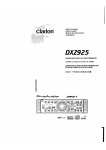
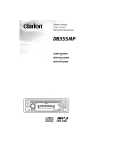
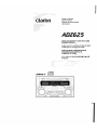
ADZ625
AM/FM CD/CASSETTE PLAYER WITH CD/MD
CHANGER CONTROL
•
RADIO 'CASoETTEAM/FM..l..ECTEUR CD AVEC
COMMANDE DE CHANGlZUR OEJtMD
•
RADIO DE AM/FM Y REPRODUCTOR DE
CD/CASETES CON CONTROL DE
CAMBIADOR D.E CD/MD
•
renNET
wo~@
DIGITAL AUDIO
Cc}l-----.--------------~-
~L_--~--&E~~~~~~~~~~~~~
IL \\
ADZ6ZS
il
'I
TUNEIVCOMPi\CT D'SC/CASSETTE PLAYER WITH SPECTRUM ANALYZER
I '\:.\ \
L'i,\\
I
:J
L?6NET
HIGHPOWER50Wx4
MAGI-TUitE
Thank you for purchasing the Clarion Product.
* Please read this owner's manual in its entirety before operating this equipment.
* After reading this manual, be sure to keep it in a handy place (e.g., glove compartment).
* Check the contents of the enclosed warranty card and keep it carefully with this manual.
* This manual includes the operating procedures of the CD changer, MD changer and TV connected
via the CeNET cable. The CD changer, MD changer and TV tuner have their own manuals, but no
explanations for operating them are described.
Contents
1.
2.
3.
4.
5.
6.
7.
8.
9.
10.
11.
2
FEATURES
PRECAUTIONS
CONTROLS
NOMENCLATURE
Names of Buttons and their Functions
Major button operations when external equipment is connected to this unit
Display Items
CAUTIONS ON HANDLING
Handling Compact Discs
Handling Cassette Tapes
REMOTE CONTROL
Inserting the Batteries
Functions of Remote Control Unit Buttons
OPERATIONS
Basic Operations
Radio Operations
CD Operations
Tape Operations
DSP/EQ Operations
Operations Common to Each Mode
OPERATIONS OF ACCESSORIES
CD/MD Changer Operations
TV Operations
IN CASE OF DIFFICULTY
ERROR DiSPLAyS
SPECiFiCATIONS
ADZ625
3
4
5
6
6!
7
8
9
9
9
10
10
11
12
12
14
15
17
19
20
22
22
24
26
27
28
•
8-Times Oversampling Digital Filter and Dual 1-Bit D/A Converters
•
•
Zero-Bit Detector™ Mute Circuit
Full Logec Tape Transport with True Function / Auto Reverse with Dual Azimuth Adjust
•
Dolby® B Noise Reduction
•
MfiGI-TUNE® FM Reception System
•
Controller for Optional TV Tuner Modules
•
Capability to Read CD TEXT Data from Clarion Compatible CD Changer
•
Built-in 5 Pre-Programmed Digital Sound Field Memories & 4 Pre-Programmed Graphic
Equalizer Memories
•
CeNET with Balanced Audio Line Transmission and Dynamic Noise Canceling
•
High Visibility Multi-Color FL Display
•
4-Channel RCA Line Level Output with Fader Control
ADZ625
3
1. When the inside of the car is very cold and
the player is used soon after switching on the
heater, moisture may form on the disc or the
optical parts of the player and proper playback may not be possible. If moisture forms
on the disc, wipe it off with a soft cloth. If moisture forms on the optical parts of the player,
do not use the player for about one hour. The
condensation will disappear naturally allowing normal operation.
j
2. Driving on extremely bumpy roads which
cause severe vibration may cause the sound
to skip.
3. This unit uses a precision mechanism. Even
in the event that trouble arises, never open
the case, disassemble the unit, or lubricate
the rotating parts.
This equipment has been tested and found to
f comply with the limits for a Class B digital de-
vice, pursuant to Part 15 of the FCC Rules.
These limits are designed to provide reasonable
protection against harmful interference in a residential installation.
This equipment generates, uses, and can radiate radio frequency energy and, if not installed
and used in accordance with the instructions,
may cause harmful interference to radio communications. However, there is no guarantee that
interference will not occur in a particular installation.
If this equipment does cause harmful interference to radio or television reception, which can
be determined by turning the equipment off and
on, the user is encouraged to consult the dealer
or an experienced radio/TV technician for help.
USE OF CONTROLS, ADJUSTMENTS, OR
PERFORMANCE OF PROCEDURES OTHER
THAN THOSE SPECIFIED HEREIN, MAY RESULT IN HAZARDOUS RADIATION EXPOSURE.
THE COMPACT DISC PLAYER SHOULD NOT
BE ADJUSTED OR REPAIRED BY ANYONE
EXCEPT PROPERLY QUALIFIED SERVICE
PERSONNEL.
CHANGES OR MODIFICATIONS NOT EXPRESSLY APPROVED BY THE MANUFACTURER FOR COMPLIANCE COULD VOID
THE USER'S AUTHORITYTO OPERATETHE
EQUIPMENT.
CHANGES OR MODIFICATIONS TO THIS
PRODUCT NOT APPROVED BY THE MANUFACTURER WILL VOID THE WARRANTY
AND WILL VIOLATE FCC APPROVAL.
clarion
MODEL
12V 8 GROUND
AM 530-171 OkHz/FM 87.9-107.9MHz
I'Iltll Par! 15 of tile FCC Rules Operation IS subject to
conditions
111 TillS device
nol cause harmful
II11CllcrCIILe.ana (21 Hlis device musl
received
Inclucllng II1lerference Illal may cause lHlclesireeJ opl2ratlon
Ti,lS P,oduct,on compiles DHHS Rules 21 C,'R sllbchClpter J applicable at
(jate of manufacture
CLARION CO LTD
50 KAMITODA lODA-SHI SAlT AMA KEi, ,j'lPAi'1
MANUF'ICTURED
DOlb) nOise reaucllorl f1l31:u f aclurecl ullder
Ille doulJle-D s\ln():](
Licensing Corporation
.
C
from Dolbv Laboratories
traelemiHks 0: Dolb\· LaboratOries
051 722 877
lin
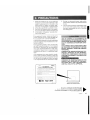
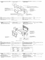
Bottom View of Source Unit
Be sure tQ unfold and read the next page.
Veui!!ez
et ilOUS referer a la page suivante.
Cerci6rese de desplegar y de leer la pagina siguiente.
ADZ625
4
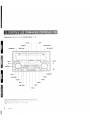
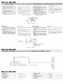
Source unit 1_IIJI-
IC
i1P'.n,,·
AiV"JI" ' "ll
ll8
~,a#',d'n
/
Unidad fuente /
r·· . ··~ [ISR]
[COIN]·"
[TAPE IN]
[SPE/ANA]
[REMOTE]
, " . " , m ••
f'" '.' [TAPE EJECT]
~
r"
l
[CD EJECT]
1
i
i
~~~ ~==I==I=-=-!!!!!!!".~~--
--- ----L~=- ~-~)l-~-~I:J
j===== ===1======1
!
---
c,ariol'
'
, [M]
[DISP]
[VOLUME]
[MUTE]
~
~
[FNC]
l.m,. '- [ROM]
[<...... ],[~>]
Note: Be sure to unfold this page and refer to the front diagrams as you read each chapter.
5
ADZ625
[BND]
Note:
• Be sure to read this chapter referring to the front diagrams of chapter "3. CONTROLS" on page 5 (unfold).
Names of the Buttons and their Functions
[REMOTE]
[DISP] button
• Receiver for remote control unit.
• Switches the display indication (Main
display,sub display,clock display).
[SPE/ANA] button
• Press to change the spectrum analyzer display.
[TAPE IN]
• Cassette tape insertion slot.
[CD IN]
• CD insertion slot.
[ISR] button
• Recalls ISR radio station in memory.
Press and hold for 2 seconds or longer: Stores
current station into ISR memory (radio mode
only).
[TAPE EJECT] button
• Ejecting a tape.
[CD EJECT] button
[BND] button
• Switches the band, or seek tuning or manual
tuning while in the radio mode.
• Plays a first track while in the CD mode.
• In tape mode, changes the side played
(direction of tape travel).
[ROM] button
• Performs random play while in the CD mode.
• Select Dolby noise reduction while in the tape
mode.
[RPT] button
• Plays repeatedly while in the CD mode.
• In the tape mode, enables repeat play. When
held depressed for one second or more,
enables blank-skip mode.
• Ejecting a CD.
[SCN] button
[DSP] button
• Performs preset scan while in the radio mode.
When the button is pressed and held, auto
store is performed.
• Performs scan play for 10 seconds for each
track while in the CD mode.
• Press to select the DSP menu, and to set DSP
effects to ON/OFF.
[T] button
• Use the button to input a title in the CD mode.
• Press and hold the button for 1 second or
longer to enter the adjust mode.
[<.....],
[~>]
buttons
[M] button
• Selects a station while in the radio mode or
selects a track when listening to a CD. These
buttons are used to make various settings.
• Use to change and store items in preset
memory.
[FNC] button
[PRESET] knob
• Stores a station into memory or recall it directly
while in the radio mode.
• In DSP/EQ mode, use to select menu.
• In adjust modes, use to select items for
adjustment.
Note:
To operate [PRESET} knob:
• Turn knob about 30 deg. (adjust item will change).
• Release finger (knob will return to original
position).
• Turn knob again (adjust item will change).
6
ADZ625
• Press the button to turn on the power.
Press and hold the button for 1 second or
longer to turn off the power.
• Switches the operation mode among the radio
mode, etc.
[MUTE] button
• Turns mute on and off.
[VOLUME] knob
• Adjust the volume by turning the knob clockwise or counterclockwise.
• Use the knob to perform various settings.
[
~II
] button
• Plays or pauses a CD while in the CD mode.
• After selecting various setting options, press
this button to confirm the settings.
[RESET] button
• Press under the following conditions.
1. Nothing happens when buttons are pressed.
2. Display is not accurate.
[A] button
• Press and hold the button for 1 second or longer
to turn the loudness on or off.
• Use the button to switch to the audio mode
(bass/mid/treble, balance/fader adjustment)
[EQ] button
• Press to select EO menu or and to set EO
effects to ON/OFF.
[T] button
• Use the button to input a title in the CD changer
mode.
• Use the button to scroll the title during CD-text
play or MD changer play in the CD changer
mode.
[
~II
] button
• Plays or pauses a CD or MD.
[<......],
[~> ]
buttons
• Selects a track when listening to a disc.
[BND] button
• Plays a first track.
_ When the TV is connected
>.:
For details, see the section "TV Operations".
[SCN] button
Major button operations
when external equipment
is connected to this unit
_When the CD/MD changer is
connected
:;: For details, see the section "CD/MD Changer
Operations".
• Performs preset scan while in the TV mode.
When the button is pressed and held, auto store
is performed.
[PRESET] knob
• Stores a station into memory or recall it directly.
[<......], [~>] buttons
• Selects a station.
[BND] button
• Switches the band, or seek tuning or manual
tuning.
[SCN] button
• Performs scan play for 10 seconds for each
track. Disc scan play is performed when the
button is pressed and held.
~
[RPT] button
• Performs repeat play. When this button is
pressed and held, disc repeat play is performed.
[ROM] button
• Performs random play. Also performs disc random play when the button is pressed and held.
[PRESET] knob
• Use to select the number of the disc loaded,
and to start play.
[DISP] button
• Switches the disc titles or track titles while in
the MD changer mode.
• Switches the user titles or track titles etc. while
in the CD changer mode.
AOZ625
7
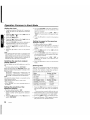
Display Items
DISC~
RPT
: Disc indication
: Repeat indication
RDM : Random indication
BLS
: BLS (Blank skip) indication
BNR : Dolby NR (B NR) indication
t L D t : Loudness indication
MANU : Manual indication
t S T t : Stereo indication
SUB : SUB indication
DSF : DSF indication
MAIN: MAIN indication
G.EQ : G.EQ indication
DEMO: DEMO (SPE-ANA) indication
'\\::,
\:;
\
,
j
f
/'
I
,!
l
/
l
I
j
/l
I
/
I
'
L
'. ,="
8
AOZ625
I
l
i, •••
/
I
",.,=,,~.,
Preset channel indication (1 to 6)
Disc number indication (1 to 12)
:~~~ti~~r:~d~fi~~~:~o~eing selected,
etc. are displayed.
Operation status indication
• The frequency, PTY, play time, CT(c1ock),
etc. are displayed.
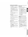
Handling Compact Discs
Use only compact discs bearing the WD1~~~ mark.
DIGITAL AUDIO
Do not play heart-shaped, octagonal, or other specially shaped compact discs.
Handling
• New discs may have some roughness around
the edges. If such discs
Ball-point pen
are used, the player may
not work or the sound Roughness
may skip. Use a ball-point
pen or the like to remove
any roughness from the
edge of the disc.
• Never stick labels on the surface of the compact disc or mark the surface with a pencil or
pen.
• Never playa compact disc with any cellophane
tape or other glue on it or with peeling off marks.
If you try to play such a compact disc, you may
not be able to get it back out of the CD player
or it may damage the CD player.
• Do not use compact discs that have large
scratches, are misshapen, cracked, etc. Use of
such discs may cause misoperation or damage.
• To remove a compact disc from its storage case,
press down on the center of the case and lift
the disc out, holding it carefully by the edges.
• Do not use
tion sheets
etc. These
breakdown
commercially available CD protecor discs equipped with stabilizers,
may damage the disc or cause
of the internal mechanism.
Storage
• Do not expose compact discs to direct sunlight
or any heat source.
• Do not expose compact discs to excess humidity or dust.
• Do not expose compact discs to direct heat from
heaters.
Cleaning
• To remove fingermarks and dust, use a soft
cloth and wipe in a straight line from the center
of the compact disc to the circumference.
• Do not use any solvents, such as commercially
available cleaners, anti-static spray or thinner
to clean compact discs.
• After using special compact disc cleaner, let the
compact disc dry off well before playing it.
Handling Cassette Tapes
Using any of the following types of cassette tapes
can cause malfunctions.
• Cassette tapes with low recording levels
• Cassette tapes in which the unrecorded section between songs is shorter than 4 seconds
• Cassette tapes with noise or the like recorded
between songs
• Cassette tapes on which there are long unrecorded sections in the middle of a song
Handling precautions
• Slack in the tape can cause malfunctions. In
particular for prerecorded
cassette tapes and 90rT~nute tapes, take up
any slack in the tape before inserting it into the
cassette player.
• Avoid using cassettes of 120 minutes or longer.
(Such cassettes have extremely thin tape, so
the tape can become stretched or cut.)
• Periodically playa cleaning cassette in the
player to clean the head.
• Keep magnets, screwdrivers, and other iron
and steel and magnetic items away from both
cassette tapes and the tape head in the player.
• Do not oil the cassette mechanism.
• Do not use any cassette tapes with peeling labels or deformed cases. Such cassette tapes
can cause breakdowns.
• When not using the player, always take the cassette out of the mechanism. Exposing a cassette to direct sunlight, extreme temperatures,
or high humidity can damage the cassette.
ADZ625
9
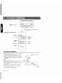
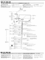
Receiver for remote
control unit
.. ~ ~ Operating range: 30° in all directions
,~
Remote control
Signal transmitter
::::1 .
Ji III CJi:~~~I"~:~;\~>]
g
[£ ],[T
Eii)
[M~~:]]_.,;.....,.L.;......I:gk ~ .
'I
seN
RPT
[BAND]
··1····
RDM
I
.mm
[DISP]
1.
[PS/AS]~~I~(.~ ~ ~""""'~==
.. [RDM]
[RPT]
l_~~_c~r~~__ j
Inserting the Batteries
1.Turn the remote control unit over, then slide the
rear cover in the direction of the arrow.
2.lnsert the AA (SUM-3, IECR-6/1.5V) batteries
that came with the remote control unit facing in
the directions shown in the figure, then close the
rear cover.
Notes:
Using batteries improperly can cause them to
explode. Take note of the following points:
Rear cover
• When replacing batteries, replace both batteries
with new ones.
• Do not short-circuit, disassemble or heat batteries.
• Do not dispose of batteries into fire or flames.
• Dispose of spent batteries properly.
10
ADZ625
Rear side
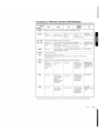
Functions of Remote Control Unit Buttons
~
Radio
Tape
CD
Button
[FUNC]
Switches among radio, CD, Tape, CD changer, MD changer and TV.
[BAND]
Switches
reception band.
Switches the
side of the tape.
Plays the first
track.
Top play.
Moves the next
disc in
increasing order.
TV
Switches
reception band.
[A],[.]
Increases and decreases volume (in all modes).
[<<llII] , [~>]
Moves preset
channels up and
down.
Fast-forward and
rewi nds tape.
APC fast-forward
and rewind.
Moves tracks up and down.
When pressed and held for 1 second:
Fast-forward/fast-backward.
Moves preset
channels up and
down.
[ ~II]
No function.
Switches between
playback and pause.
Switches between playback and
pause.
No function.
[MUTE]
Turns mute on and off.
[ISR]
Recalls ISR radio station in memory.
Press and hold for 2 seconds or longer: Stores current station into ISR memory
(radio mode only).
[DISP]
Switches among main display, sub display and clock (CT) display.
[SCN]
Preset scan.
When pressed
and held for 2
seconds: Auto
store.
Fast-forward
scan.
Scan play.
Scan play.
When pressed
and held for 1
second: Disc
scan play.
Preset scan.
When pressed
and held for 2
seconds: Auto
store.
[RPT]
No function
Repeat play.
When pressed
and held for 1
second:
Blank tape skip
function turns
on and off.
Repeat play.
Repeat play.
When pressed
and held for 1
second: Disc
repeat play.
No function.
[ROM]
No function
Select Dolby
Noise Reduction mode.
Random play.
Random play.
When pressed
and held for 1
second: Disc
random play.
Switches
between TV and
VTR.
(
*
CDIMD
changer
Some of the corresponding buttons on the main unit and remote control unit have different functions.
AOZ625
11
.....................
Basic Operations
Note: Be sure t6 read this chapter referring to the front diagrams of
chapter "3. CONTROLS" on page 5 (unfold).
Be sure to lower the volume before switching off the unit power or the ignition key. The
unit remembers its last volume setting. If you
switch the power off with the volume up, when
you switch the power back on, the sudden
loud volume may hurt your hearing and damage the unit.
The clock is displayed when the ignition key
is turned to the ACC (accessory) or IGN (ignition-on) position even when the unit power is
off. In some cars, the clock may momentarily
disappear when the ignition key is turned to
the START position. The clock will reappear
after the engine has started and the ignition
key is released to the IGN (ignition-on) position.
Turning on/off the power
Notes:
• Be careful about using this unit for a long time without running the engine. If you drain the car's battery too far, you may not be able to start the engine and this can reduce the service life of the
battery
• System check
This unit checks what external equipment is connected to the CeNET The first time the ACC/lgnition is turned on (initialization), "SYSTEM" and
"Push PWR" alternately blink in the display Press
the [FNC} button to start the system check. When
complete, press the [FNC} button again to activate
the unit then the unit appears CHECKING COMPLETE.
1. Press the [FNC] button.
2. The illumination and display on the unit light
up. The unit automatically remembers its last
operation mode and will automatically switch
to display that mode.
3. Press and hold the [FNC] button for 1 second
or longer to turn off the power for the unit.
Selecting a mode
1. Press the [FNC] button to change the mode
of operation.
2. Each time you press the [FNC] button, the
mode of operation changes in the following
order:
12
AOZ625
Radio mode -+ CD mode -+ Tape mode
CD changer mode -+ MD changer mode
TV mode -+ AUX mode -+ Radio mode ...
-+
-+
", External equipment not connected with CeNET
is not displayed.
Adjusting the volume
Turn the [VOLUME] knob clockwise to increase
the volume, or turn the [VOLUME] knob counterclockwise to decrease the volume.
)
", The volume level is from 0 (minimum) to 33 (maximum).
Switching the display
Press the [DISP] button to select the desired display.
Each time you press the [DISP] button, the display switches in the following order:
Main display
]
[
Sub (title) display
]
[
Clock(CT) display
~
Main display
':' Once selected, the preferred display becomes
the display default. When a function adjustment
such as volume is made, the screen will momentarily switch to that function's display, then
revert back to the preferred display several
seconds after the adjustment.
':' When you have entered a title in a CD, it appears in the sub display. If you have not entered a title, "NO-TTL" appears in the title display instead. For information on how to enter a
title, refer to the subsection "Entering titles"
in the "Operations Common to Each Mode".
':' You can adjust the way of scrol!ing a title. For
the details on it, refer to the subsection "Adjusting the way of scrolling" in the
"Operations Common to Each Mode".
Basic Operations
Adjusting the bass
Turning on/off the loudness
1. Press the [A] button and select "BASS".
The loudness effect emphasizes the bass and
treble to create a natural sound tone. When you
are listening to music at a low volume, it is recommended to use the loudness effect.
2. Turn the [VOLUME] knob clockwise to
emphasize the bass, or turn the [VOLUME]
knob counterclockwise to attenuate the bass.
:;: The factory default setting is "0". (Adjustment
range: -6 to +6)
3. When the adjustment is complete, press the
[A] button several times until the function
mode is reached.
Adjusting the treble
1. Press and hold the [A] button for 1 second or
longer to turn on the loudness effect. When
the loudness effect is turned on, "LOUD" lights
in the display.
2. Press and hold the [A] button for 1 second or
longer to turn off the loudness effect. "LOUD"
goes off in the display.
1. Press the [A] button and select "TREB".
2. Turn the [VOLUME] knob clockwise to
emphasize the treble, or turn the [VOLUME]
knob counterclockwise to attenuate the treble.
:;: The factory default setting is "0". (Adjustment
range: -6 to +6)
3. When the adjustment is complete, press the
[A] button several times until the function
mode is reached.
Adjusting the balance
1. Press the [A] button and select "BAL".
2. Turn the [VOLUME] knob clockwise to
emphasize the sound from the right speaker,
or turn the [VOLUME] knob counterclockwise
to emphasize the sound from the left speaker.
:;: The factory default setting is "0". (Adjustment
range: L13 to R13)
3. When the adjustment is complete, press the
[A] button several times until the function
mode is reached.
Adjusting the fader
1. Press the [A] button and select "FAD".
2. Turn the [VOLUME] knob clockwise to
emphasize the sound from the front speakers, or turn the [VOLUME] knob counterclockwise to emphasize the sound from the rear
speakers.
:;: The factory default setting is "0". (Adjustment
range: F12 to R12)
3. When the adjustment is complete, press the
[A] button several times until the function
mode is reached.
AOZ625
13
Radio Operations
FM reception
Manual tuning
For
There are 2 ways available: Quick tuning and step
tuning.
When you are in the step tuning mode, the frequency changes one step at a time. In quick tuning mode, you can quickly tune the desired frequency.
1. Press the [BND] button and select the desired
band (FM or AM).
enhanced
FM
performance the
tuner includes signal actuated
stereo control and Multipath noise reduction circuits.
MfiGI-TUHE®
Changing the reception area
This unit is initially set to USA frequency intervals
of 10kHz for AM and 200kHz for FM. When using it
outside the USA, the frequency reception range
can be switched to the intervals below.
• Setting the reception area
1. Press the [FNC] button and select the radio
mode (FM or AM).
2. While pressing the [DISP] button, each time
you press and hold the [SPEIANA] button for
2 seconds or longer, the reception area
switches from inside the USA to outside the
USA or from outside the USA to inside the USA.
* Any station preset memories are lost when the
reception area is changed.
* If
"MANU" is not lit in the display, press and
hold the [BND] button for 1 second or longer.
"MANU" lights in the display and manual tuning is now available.
2. Tune into a station.
• Quick tuning:
Press and hold the [~> ] button or the [ <~] button for 1 second or longer to manually tune to
the desired frequency.
'
• Step tuning:
Press the [~>] button or the [<~] button to
manually tune one step at a time to the desired
frequency.
Listening to the radio
1. Press the [FNC] button and select the radio
mode.
2. Press the [BND] button and select the radio
band. Each time the button is pressed, the
radio reception band changes in the following order:
FM1 ... FM2'" FM3'" AM ... FM1 ...
3. Press the [~> ] button or the [ <~] button to
tune in the desired station.
Tuning
There are 3 types of tuning mode available, seek
tuning, manual tuning and preset tuning.
Seek tuning
1. Press the [BND] button and select the desired
band (FM or AM).
* If "MANU"
is lit in the display, press and hold
the [BND] button for 1 second or longer.
"MANU" in the display goes off and seek tuning is now available.
2. Press the [~> ] button or the [ <~] button to
automatically seek to the next station.
When the [~>] button is pressed, the station is sought in the direction of higher frequencies; if the [<~] button is pressed, the
station is sought in the direction of lower frequencies.
14
ADZ625
Storing a preset station
A total of 24 preset positions (6-FM1, 6-FM2, 6FM3, 6-AM) exists to store individual radio stations in memory.
Manual memory
1. Select the desired station with seek tuning,
manual tuning or preset tuning.
2. Press the [M] button.
"CH" is lit in the display.
3. Turn the [PRESET] knob either clockwise or
counterclockwise to select the desired preseet
memory.
4. Press and hold the [M] button for 2 seconds
or longer to store that station into preset
memory.
Auto store
Auto store selects up to 6 stations and automatically stores them into preset memory. If auto
store cannot tune in all six stations, then it stores
the strongest stations into memory and the other
presets untouched.
1. Press the [BND] button and select the desired
band (FM or AM).
2. Press and hold the [SCN] button for 2 seconds or longer. The stations with good reception are stored automatically to the preset
memory.
Radio Operations
CD Operations
Recalling a preset station
Loading a CD
Turn the [PRESET] knob either clockwise or
counterclockwise to recall the stored radio frequency automatically.
Insert a CD into the center of the insertion slot
with the label side facing up. The CD plays automatically after loading.
Notes:
• Never insert foreign objects into the CO insertion
slot.
• When a CO is loaded in the unit, never try to insert another CO in this case.
1. Press the [BND] button and select the desired
band (FM1, FM2, FM3 or AM).
2. Turn the [PRESET] knob either clockwise or
counterclockwise to recall the stored station.
[]jCOMPACT
Preset scan
Preset scan receives the stations stored in preset memory in order. This function is useful when
searching for a desired station in memory.
1. Press the [SCN] button.
2. When a desired station is tuned in, press the
[SCN] button again to continue receiving that
station.
Note:
• Be careful not to press and hold the [SCN} button
for 2 seconds or longer, otherwise the auto store
function engages and the unit starts storing stations.
Instant station recall (ISR)
Instant station recall is a special radio preset that
instantly accesses a favorite radio station at a
touch of a button. The ISR function even operates with the unit in other modes.
elSR memory
1. Select the station that you wish to store in ISR
memory.
2, Press and hold the [ISR] button for 2 seconds
or longer.
e
Recalling a station with ISR
{n any mode, press the [ISR] button to turn on
the radio function and tune the selected radio station. "ISR" appears in the display. Press the [ISR]
button again to return to the previous mode.
• Discs not bearing the O~IO~~ mark and CO-ROMs
cannot be played by this unit.
• Some COs recorded in CD-R mode may not be
usable.
• Even when recorded in CD-RW mode, some COs
not be usable.
Listening to a CD already inserted
Press the [FNC] button to select the CD mode.
Play starts automatically. If no CD is loaded in
the unit, "NO DISC" appears in the display.
Pausing play
1. Press the [~II] button to pause play.
"PAUSE" appears in the display.
2. To resume CD play, press the [~II] button
again.
Displaying CD titles
This unit can display title data for user titles input
with this unit.
Press the [DISP] button to display the title.
Notes:
• Titles of CO-text COs cannot be displayed with this
unit.
• If the CO playing is a CO-text CO or no user title
has been input, {fl NO- TTL appears in the
display.
11
Ejecting a CD
Press [CD EJECT] button to eject the CD. Take
it out from the ejected position.
'" If a 5/1 CD (12 cm) is left in the ejected position for
15 seconds, the CD is automatically reloaded (Auto
reload).
:;: 3/1 CDs (8 cm) are not auto reloaded. Be sure to
remove it when ejected.
Notes:
• If you force a CD into before auto reloading,
this can damage the CD.
;f: The radio mode is selected automatically 4 seconds after the [CD EJECT} button is pressed.
AOZ625
15
CD Operations
Selecting a track
Repeat play
• Track-up
1. Press the [~> ] button to move ahead to the
beginning of the next track.
The repeat play continuously plays the current
track. This function continues automatically until
it is canceled.
2. Each time you press the [~>] button, the
track advances ahead to the beginning of the
next track.
1. Press the [RPT] button. "T-REPEAT" lights in
the display and the current track is repeated.
• Track-down
1. Press the [<~] button to move back to the
beginning of the current track.
2. Press the [<~] button twice to move to the
beginning of the previous track.
Fast-forward/fast-backward
• Fast-forward
Press and hold the
longer.
[~> ]
button for 1 second or
• Fast-backward
Press and hold the [ <~] button for 1 second or
longer.
Top function
The top function resets the CD player to the first
track of the disc. Press the [BND] button to play
the first track (track No.1) on the disc.
Scan play
The scan play locates and plays the first 10 seconds of each track on a disc automatically. This
function continues on the disc until it is canceled.
* The scan play is useful when you want to select a
desired track.
1. Press the [SCN] button to start track scanning. "T-SCAN" lights in the display.
2. To cancel the scan play, press the [SCN] button again. "T-SCAN" goes off from the display
and the current track continues to play.
16
ADZ625
2. To cancel the repeat play, press the [RPT]
button again. "T-REPEAT" goes off from the
display and normal play resumes.
Random play
The random play selects and plays individual tracks
on a disc in no particular order. This function continues automatically until it is canceled.
)
1. Press the [ROM] button. "T-RANDOM" lights
in the display, an individual track is selected
randomly and play begins.
/oJ
2. To cancel the random play, press the [ROM]
button again. "T-RANDOM" goes off from the
display and normal play resumes.
Tape Operations
Loading a tape
Load a tape into the cassette tape insertion slot.
"LOADING" appears in the display and starts
playing.
", When a metal or chrome bias (70/1 sec) tape is
inserted, the metal bias setting is selected automatically.
:;' The cassette tape slot door shuts automatically
after inserting or ejecting a tape ("Auto shut door
function"). It protects the tape mechanism from
any dust.
Listening to a tape already inserted
Press the [FNC] button to select the tape mode.
Play starts automatically. If no tape is loaded in
the unit, "NO CASS" appears in the display.
Pausing play
• Listening to another source while using FF
or REW ("monitor mode")
To listen to the CD, CD/MD changer or AM/FM
tuner while the mechanism searches, press the
[FNC] button to select the desired mode. The
mechanism will stop automatically when the end
of the tape is reached.
Note:
• Use the [FNC} button and select the tape function
to resume tape playback.
APe (Auto Program Control) function
The APC function allows the tape to skip forward
to the beginning of the next track or rewind to the
start of the current track.
• Skipping forward to the next track ("APCFF")
1. Press the [~II] button to pause play.
"PAUSE" appears in the display.
During tape playback, press the [~>] button
twice to fast-forward to the next track. The next
track stars playing.
2. To resume tape play, press the [~II] button
again.
• Skipping backward to the current track
("APC-R EW")
Ejecting a tape
During tape playback, press the [<..... ] button
twice to rewind to the start of the current track.
The current track plays from the beginning.
Press the [TAPE EJECT] button to eject a tape.
Take it out from the ejected position.
';' The radio mode is selected automatically 4 seconds after the [TAPE EJECT] button is pressed.
Switching to the other side of the tape
Press the [BND] button to change tape direction
and playback.
", The tape mechanism automatically reverses direction and engage playback at the end of the tape
(auto reverse).
Fast-forward/fast-backward
• Fast-forward
Press the [~> ] button.
• Fast-backward
Press the [<..... ] button.
• Canceling FF/REW
Press the [~II] button.
• Canceling FF/REW APC to resume playback
Press the [~II] button.
• Listening to another source while using
APC ("monitor mode")
To listen to the CD, CD/MD changer or AM/FM
tuner while the mechanism searches, press the
[FNC] button to select the desired mode. The
mechanism will stop automatically when it finds
the next track (in FF APC) or the start of the current track (in REW APC).
Note:
• Use the [FNC} button and select the tape function
to resume tape playback.
Dolby noise reduction system
The Dolby noise reduction system increases the
volume level of high frequency sounds during
recording and sets it back to their original level
during play. This system reduces hissing noise
which is typical of cassette tapes.
:;: Dolby noise reduction manufactured under license
from Dolby Laboratories Licensing Corporation.
Dolby and the double-D symbol are trademarks of
Dolby Laboratories Licensing Corporation.
Press the [ROM] button to select Dolby noise reduction. "B NR" lights in the display. Each time
you press the [ROM] button, the Dolby toggles
between B NR and OFF.
ADZ625
17
Tape Operations
Intra tape scan play
The intro tape scan allows the first 10 seconds of
all the tracks on the tape to be played. This function continues on the tape until it is canceled.
1. Press the [SCN] button to start Intro tape scan.
"SCAN" lights in the display.
2. To cancel the intro tape scan, press the [SeN]
button again. "SCAN" goes off from the display and the current track continues to play.
* When
the end of the tape is reached during
the intro tape scan, the tape mechanism automatically reverses direction and continues the
intro tape scan.
* If you select another mode during the intro tape
scan, the mechanism automatically makes the
intro tape scan stop when it finds the next track
(APe function).
Tape repeat play
The tape repeat continuously plays the current
track. This function continues automatically until
it is canceled.
1. Press the [RPT] button. "REPEAT" lights in
the display and the current track is repeated.
2. To cancel the repeat play, press the [RPT]
button again. "REPEAT" goes off from the display and normal play resumes.
Blank tape skip
The blank tape skip allows you to skip blank sections of tape that are over 12 seconds long.
1. Press and hold the [RPT] button for 1 second
or longer. "BLS" lights in the display and the
mechanism fastforward to the next track selection.
2. To cancel the blank tape skip, press and hold
the [RPT] button again. "BLS" goes off and
normal play resumes.
Notes:
The APe, intra tape scan, tape repeat and blank
skip may not work properly with tapes of the following qualities:
• Tapes on which the recording level is too low.
• Tapes on which there is much noise between selections.
• Tapes on which there are long pauses in the middle
of selections.
• Tapes on which there are less than 4 seconds of
blank space between selections.
18
ADZ625
DSPIEQ Operations
Select DSP Menu
Selecting the EO menu
About DSP functions:
About the EO function:
The Digital Sound Processor use digital signal
processing to allow the creation of simulated
audio environments inside your car, without
degradation of the sound.
The Equalizer allows correction and modification
of the frequency response for selected frequency
ranges, thus allowing the creation of your own
unique sound.
1. Press the [DSP] button. The DSF indicator will
flash.
1. Press the [EO] button.
2. Turn the [PRESET] knob either clockwise or
counterclockwise to select the DSP menu.
2. Turn the [PRESET] knob either clockwise or
counterclockwise to select the desired EO
menu .
• DSP menus
• EO menus
STADIUM: Large stadium without roof or walls.
IMPACT
: Low and high
emphasized.
B-BOOST
: Low frequencies emphasized.
HALL
: Large concert hall.
CLUB
: Club with strong bass.
CHURCH : Church with a vaulted ceiling.
L-ROOM
: Listening room in a home.
3. Press the [DSP] button to return to the original
mode.
To set DSP effects to ON/OFF
Hold the [DSP] button depressed for 1 second
or more.
Each time the [DSP] button is held depressed,
the function alternates between ON and OFF.
When the DSP function is ON, the DSF indicator
lights.
frequencies
ACOUSTIC: Medium frequencies (vocals)
emphasized.
FLAT
: Original sound.
3. Press the [EO] button to return to the original
mode.
Setting EO effects to ON/OFF
Hold the [EO] button depressed for 1 second or
more.
Each time the [EO] button is held depressed in
this way, the function alternates between ON and
OFF. When the EO function is enabled (ON), the
G.EO indicator lights.
To adjust EFFECTS
About sound effects:
"Effects" refers to the characteristic
reverberations and echoes that occur when
sound is bounced off walls or other surfaces. This
unit allows the amount of echo or reverberation
to be adjusted.
1. Press the [DSP] button. The DSF indicator
flashes.
2. Turn the [PRESET] knob either clockwise or
counterclockwise to select the desired DSP
menu adjust item.
3. Hold the [T] button depressed for 1 second or
more.
4. Turn the [VOLUME] knob either clockwise or
counterclockwise to adjust the effect.
• The amount of effect added can be adjusted
within the range 0-70%.
5. Press the [T] button to return to the DSP
menu. The selected DSP menu will appear.
6. Press the [DSP] button to return to the original
mode.
AOZ625
19
Operation Common to Each Mode
Setting the clock
1. Press and hold the [T] button for 1 second or
longer to switch to the adjustment selection
display.
2. Press the [~> ] button or the [ <......] button to
select "CLOCK
I)".
3. Press the [~II] button.
4. Press the [~>] button or the [<...... ] button to
select the hour or the minute.
5. Turn the [VOLUME] knob either clockwise or
counterclockwise to set the correct time.
* The clock is displayed
in 12-hour format.
6. Press the [~II] button to store the time into
memory.
3. Turn the [VOLUME] knob either clockwise or
counterclockwise to set the sensitivity of the
spectrum analyzer.
You can choose one of "LOW", "MID" or
"HIGH" for the sensitivity of the spectrum analyzer.
4. Press the [T] button to return to the previous
mode.
Setting the speed of the spectrum
analyzer display
:,: The factory default setting is "HIGH".
)
1. Press and hold the [T] button for 1 second or
longer to switch to the adjustment selection
display.
7. Press the [T] button to return to the previous
mode.
Note:
• You cannot set the clock when it is displayed with
only the ignition on. If you drain or remove the car's
battery or take out this unit, the clock is reset. While
setting the clock, if another button or operation is
selected, the clock set mode is canceled.
3. Turn the [VOLUME] knob either clockwise or
counterclockwise to set the speed of the spectrum analyzer display.
Switching the spectrum analyzer
display patterns
4. Press the [T] button to return to the previous
mode.
2. Press the [~> ] button or the [<...... ] button~to
select "ANA SPD".
You can choose one of "LOW", "MID" or
"HIGH" for the speed of the spectrum analyzer display.
You can select one out of 8 patterns or set it to
off.
Entering titles
* The factory default setting
Titles up to 10 characters long can be stored in
memory and displayed for radio or TV stations
and CDs. The numbers of titles that can be entered for each mode are as follows.
is "PATTERN 1".
Each time you press the [SPE/ANA] button, the
spectrum analyzer display pattern changes in the
following order:
PATTERN 1 ~ PATTERN 2 ~ PATTERN 3 ~
PATTERN 4 ~ PATTERN 5 ~ PATTERN 6 ~
PATTERN 7 ~ SCAN ~ OFF ~ PATTERN 1...
Note:
The spectrum analyzer display is unavailable during
these operations below;
• Seek tuning and auto store in radio mode.
• Mute or pause.
• When "NO DISC" or an error message appears in
the display.
Mode
Number of titles
Radio mode
30 titles
CD mode
100 titles
TV mode
15 titles
CD changer mode
Number of titles
CDC655z connected
60 titles
CDC655Tz connected
100 titles
CDC1255z connected
50 titles
Setting the sensitivity of the
spectrum analyzer
* The factory default setting is "MID".
1. Press the [FNC] button to select the mode you
want to enter a title. (radio, CD, CD changer or
TV)
1. Press and hold the [T] button for 1 second or
longer to switch to the adjustment selection
display.
:,: Titles cannot be entered for MDs with this unit.
2. Select and playa CD or a CD in the CD changer,
or tune to an appropriate TV or radio station.
2. Press the [~> ] button or the [ <......] button to
select "ANA SENS".
3. Press the [DISP] button and display the title.
20
ADZ625
4. Press the [T] button. "TITL" appears in the display and the cursor position flashes.
Operation Common to Each Mode
5. Press the [~> ] button or the [<...... ] button to
move the cursor.
6. Press the [DISP] button to select a character.
Each time you press the [DISP] button, the
character changes in the following order:
Capital letters -+ Small letters
Symbols -+ Capital letters ...
-+
Numbers/
7. Turn the [VOLUME] knob either clockwise or
counterclockwise to select the desired
character. Pressing the [~>] button moves
the cursor to the next character; pressing the
[<......] button moves the cursor to the previous
character.
8. Repeat steps 5 to 7 to enter up to 10 characters for the title.
9. Press and hold the [~II] button for 2 seconds or longer to store the title into memory
and cancel title input mode.
Clearing titles
1. Playa CD or a CD in a CD changer, or tune a
radio station or TV station that you want to
clear the title for.
2. Press the [DISP] button and display the subtitle.
3. Press the [T] button. "TITL" appears in the display and the display switches to the title input
display.
4. Press the [BND] button.
Clock function
• Time matching
Regarding the "CLOCK INDICATION"...
The unit indicates the clock when the car engine
is running (when ACC is ON).
The clock is of 12-hour indication.
1. Press the [T] button continuously (for about 1
second). "ANA_SENS" is indicated.
2. Press the [<...... ] button or the [~>] button
and select "CLOCK
I)"
3. Press the
[~II]
button to indicate the clock.
The clock indicates "AM 12:00" and turns to
the "time setting" mode.
4. Press the [<......] button or the [~>] button
and select "HOUR" or "MINUTE" may adjust
items which are flashing.
5. Press the [~>] button or the [<......] button
and match the time.
6. Press the
[~II]
button.
7. Press the [T] button.
The unit returns to the original indication.
Triggered audio mute for cellular
telephones
This unit requires special wiring to mute the audio signal automatically when a cellular telephone
rings in the car.
5. Press and hold the [~II] button for 2 seconds or longer to clear the title and cancel
the title input mode.
:" This function is not compatible with all cellular telephones. Contact your local authorized Clarion
dealer for information on proper installation and
compatibility.
Message display
Adjusting the way of title scrolling
When the unit is powered on or off, a message is
displayed. The user can turn this message display on or off.
There are 3 ways for scrolling a title in the display. You can select the way you prefer.
i, :,:
The factory default setting is "ON".
1. Press and hold the [T] button for 1 second or
longer to switch to the adjustment selection
display.
2. Press the [~> ] button or the [<...... ] button to
select "MESSAGE".
:;: The factory default setting is "AUTO".
1. Press and hold the [T] button for 1 second or
longer to switch to the adjustment selection
display.
2. Press the [~> ] button or the [<......] button to
select "SCROLL".
3. Turn the [VOLUME] knob clockwise to set the
message display to "ON", or turn the [VOLUME] knob counterclockwise to set the message display to "OFF".
3. Turn the [VOLUME] knob to change the
display. Each time the [VOLUME] knob is
turned either clockwise or counterclockwise,
the display changes between the 2 display
methods available.
4. Press the [T] button to return to the previous
mode.
4. Press the [T] button to return to the previous
mode.
ADZ625
21
CD/MD Changer Operations
CD/MD changer functions
• If a CD-text CD is not input its disc title or a track
When an optional CD/MD changer is connected
through the CeNET cable, this unit controls all
CD/MD changer functions. This unit can control
a total of 2 changers (MD and/or CD).
Press the [FNC] button and select the CD(MD)
changer mode to start play. If 2 CD(MD) changers are connected, press the [FNC] button to
select the CD(MD) changer for play.
*
If "NO MAGA" appears in the display, insert the
magazine into the CD changer. "CHECK" appears
in the display while the player loads (checks) the
magazine.
* If "NO DISC" appears in the display, eject the magazine and insert discs into each slot. Then, reinsert
the magazine back into the CD changer.
* If "NO DISC" appears in the display, load MDs into
the MD changer.
title, "TEXTIJITTL" or "TEXTflTTL" appears in the
display
Switching disc titles and track titles
(MD)
This unit can display disc titles and track titles
already entered on MOs. Titles up to 128 characters long can be displayed by scrolling the titles.
* Titles cannot be
entered for MDs with this unit.
1. Press the [DISP] button to display the title)
The disc title or track title is displayed.
2. Each time you press and hold the [DISP] button for 1 second or longer, the display toggles
k
between the disc title and the track title. ~,
Note:
• If an MD is not input its disc title or a track title, "IJI
TITLE" or 'fl TITLE" appears in the display
Procedure to scroll a title
CD"ROM dlscsal'1dCD"R discs cannot be
Pausing play
Set "AUTO SCROLL" to "AUTO" or "OFF". (The
factory default setting is "AUTO". Refer to
subsection "Adjusting the way of title scrolling"
in section "Operations Common to Each Mode".)
1. Press the [~II] button to pause play.
"PAUSE" appears in the display.
• When set to "AUTO"
The title is automatically kept scrolling.
played in the CD changer.
2. To resume play, press the
[~II]
button again.
• When set to "OFF"
Press the [T] button to scroll the title.
Displaying CD titles
This unit can display title data for CD-text CDs
and user titles input with this unit.
* Title
data for CD-text CDs can be displayed with
this unit only when it is connected to CDC655Tz.
• When connected to CDC655z or CDC1255z
Selecting a CD/MD
Turn the [PRESET] knob either clockwise or
counterclockwise to select a CD or MD.
* Use to
select the number of the disc loaded, and
to start play.
Press the [DISP] button to display the title.
• When connected to CDC655Tz
Selecting a track
1. Press the [DISP] button to display the title.
• Track-up
1. Press the [~> ] button to move ahead to the
beginning of the next track.
2. Each time you press and hold the [DISP] button for 1 second or longer, the title display
changes in the following order:
User title (disc) ~ CD-text title (disc) ~ CDtext title (track) ~ user title (disc) ...
Notes:
• If the CD playing is not a CD-text CD or no user
title has been input, "USER TTL" appears in the
display
22
ADZ625
2. Each time you press the [~>] button, the
track advances ahead to the beginning of the
next track.
• Track-down
1. Press the [<...... ] button to move back to the
beginning of the current track.
2. Press the [<...... ] button twice to move to the
beginning of the previous track.
CD/MD Changer Operations
Fast-forward/fast-backward
Disc repeat play
• Fast-forward
After all the tracks on the current disc have been
played, the disc repeat play automatically replays
the current disc over from the first track. This function continues automatically until it is cancelled .
Press and hold the [~> ] button for 1 second or
longer.
• Fast-backward
Press and hold the [ <~] button for 1 second or
longer.
1. Press and hold the [RPT] button for 1 second
or longer. "DISC ~" and "D-REPEAT" light in
the display and the disc repeat play starts.
Scan play
2. To cancel the disc repeat play, press and hold
the [RPT] button again. "DISC~" and "0REPEAT" go off from the display and normal
play resumes on the current track.
The scan play locates and plays the first 10 seconds of each track on a disc automatically. This
function continues on the disc until it is cancelled.
';: The scan play is useful when you want to select a
desired track.
1. Press the [SCN] button to start track scanning. "T-SCAN" lights in the display.
2. To cancel the scan play, press the [SCN] button again. "T-SCAN" goes off from the display
and the current track continues to play.
Disc scan play
The disc scan play locates and plays the first 10
seconds of the first track on each disc in the currently selected CD/MD changer. This function
continues automatically until it is cancelled.
:;: The disc scan play is useful when you want to select a desired CD/MD.
1. Press and hold the [SCN] button for 1 second
or longer. "DISC~" and "D-SCAN" light in the
display and the disc scan play starts.
2. To cancel the disc scan play, press the [SCN]
button aga1n. "DISC ~"and "D-SCAN" go off from
the display and the current track continues to
play.
Random play
The random play selects and plays individual
tracks on the disc in no particular order. This function continues automatically until it is cancelled.
1. Press the [ROM] button. "T-RANDOM" lights
in the display and the random play begins.
2. To cancel the random play, press the [ROM]
button again. "T-RANDOM" goes off from the
display and normal play resumes.
Disc random play
The disc random play selects and plays individual
tracks or discs automatically in no particular order. This function continues automatically until it
is cancelled.
1. Press and hold the [ROM] button for 1 second
or longer. "DISC ~" and "D-RANDOM" light in
the display and the disc random play starts.
2. To cancel the disc random play, press and
hold the [ROM] button again. "DISC~" and "0RANDOM" go off from the display and normal play resumes from the current track.
R,epeat play
The repeat play continuously plays the current
track. This function continues automatically until it
is cancelled.
(
1. Press the [RPT] button. "T-REPEAT" lights in
the display and the current track is repeated.
2. To cancel the repeat play, press the [RPT] button again. "T-REPEAT" goes off from the display and normal play resumes.
ADZ625
23
TV Operations
TV tuner functions
Manual tuning
When an optional TV tuner is connected through
the CeNET cable, this unit controls all TV tuner
functions. To watch TV requires a TV tuner and
monitor.
There are 2 ways available: Quick tuning and step
tuning.
Watching a TV
1. Press the [FNC] button and select the TV
mode.
2. Press the [BND] button to select the desired
TV band (TV1 or TV2). Each time the button
is pressed, the input selection toggles between TV1 and TV2.
When you are in the step tuning mode, the frequency changes one step at a time. In quick tuning mode, you can quickly tune the desired frequency.
1. Press the [BND] button and select the desired
band (TV1 or TV2).
:1: If "MANU" is not lit in the display, press and
hold the [BND] button for 1 second or longer.
"MANU" lights in the display and manual tuning is now available.
2. Tune into a station.
3. Press the [ <......] button or the [~> ] button to
tune in the desired TV station.
• Quick tuning:
Watching a video
Press and hold the [<...... ] button or the [~>] button for 1 second or longer to tune in a station..
The TV tuner has a VTR input terminal to which
1 external device can be connected. Connect a
12 V video cassette player (VCP) or video cassette recorder (VCR) to the TV tuner input terminal.
• Step tuning:
1. Press the [ROM] button to select VTR.
A total of 12 TV stations can be stored (6-TV1
and 6-TV2). This allows you to select your favorite TV stations and store them in memory for later
recall.
2. To return to the TV broadcast, press the [ROM]
button.
Tuning
There are 3 types of tuning mode available, Seek
tuning, manual tuning and preset tuning.
Seek tuning
1. Press the [BND] button and select the desired
TV band (TV1 or TV2).
* If "MANU" is lit in the display, press and hold
the [BND] button for 1 second or longer.
"MANU" in the display goes off and seek tuning is now available.
2. Press the [<......] button or the [~>] button to
automatically seek a station. Press the [~>]
button to automatically tune up the frequency
band to the next available TV station; press
the [<......] button to automatically tune down.
24
AOZ625
Press the [<...... ] button or the [~>] button to
manually tune in a station.
Recalling a preset station
1. Press [BND] button and select the desired TV
band (TV1 or TV2).
2. To recall a stored TV station, turn the [PRESET] knob either clockwise or counterclockwise to select that station.
Manual memory
1. Select the desired station with seek tuning,
manual tuning or preset tuning.
2. Press the [M] button.
"CH" is lit in the display.
3. Turn the [PRESET] knob either clockwise or
counterclockwise to select the desired preseet
memory.
4. Press and hold the [M] buttos for 2 seconds
or longer to store that station into preset
memory.
TV Operations
Auto store
Auto store selects 6 TV stations automatically
and stores each one into a preset memory.
If there are not 6 stations with good reception,
stations previously stored in memory remain and
only the strong stations are stored into memory.
1. Press the [BND] button and select the desired
TV band (TV1 or TV2).
2. Press and hold the [SCN] button for 2 seconds or longer. The stations with good reception are stored automatically to the preset
memory.
Preset scan
Preset scan allows the user to view each preset
position before it automatically advances to the
next preset. This function is useful for searching
for desired TV station in memory.
1. Press the [SCN] button.
2. When the desired station is found, press the
[SCN] button again to remain tuned to that
station.
Note:
• Do not press and hold the [SeN} button for 2 seconds or longer. Doing so will trigger the auto store
function and start storing stations into memory
Setting the TV diver
You can change the reception setting for the TV
antenna connected to the TV tuner.
1. Press and hold the [T] button for 1 second or
longer to switch to the adjustment selection
display.
2. Press the [<~] button or the [~>] button to
select "TV DIVER".
3. Turn the [VOLUME] knob clockwise to set to
"ON" or counterclockwise to set to "OFF".
eON:
Sets reception emphasizing the visual.
eOFF:
Sets the diver setting to OFF.
4. Press the [T] button to return to the previous
mode.
ADZ625
25
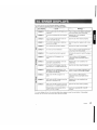
Problem
Power does not turn
on.
(No sound is produced.)
No sound output
when operating the
unit with amplifiers or
power antenna attached.
'i!
Cause
Fuse is blown.
Replace with a fuse of the same amperage. If
the fuse blows again, consult your store of purchase.
Incorrect wiring.
Consult your store of purchase.
Power antenna lead is shor- 1. Turn the unit off.
2. Remove all wires attached to the power antented to ground or excessive
na lead. Check each wire for a possible short
current is required for remote-on the amplifiers or
to ground using an ohm meter.
3. Turn the unit back on.
power antenna.
4. Reconnect each amplifier remote wire to the
power antenna lead one by one. If the amplifiers turn off before all wires are attached, use
an external relay to provide remote-on voltage
(excessive current required).
ep
c pl-------------If------------t---------------------,I
e
CD Nothing happens
The microprocessor has
malfunctioned due to noise,
etc.
Press the reset button with a thin rod.
Compact disc cannot
be loaded.
Another compact disc is already loaded.
Eject the compact disc before loading the new
one.
Sound skips or is no isy.
Compact disc is dirty.
Clean the compact disc with a soft cloth.
Compact disc is heavily
scratched or warped.
Replace with a compact disc with no scratches.
Sound is bad directly
after power is turned
on.
Water droplets may form on
the internal lens when the
car is parked in a humid
place.
Let dry for about 1 hour with the power on.
Sound quality is poor.
Playback head is dirty.
Use a cleaning tape, etc., to clean the head.
[ROM] button is not pres-
When listening to a tape recorded with Dolby
NR, press [ROM] button and select B NR.
when buttons are
pressed.
Display is not accurate.
Q
(.)
ep
.~
I!J.
sed.
26
ADZ625
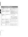
If an error occurs, one of the following displays is displayed.
Take the measures described below to eliminate the problem.
l
Measure
IirrQf>Display
ERROR 2
A CD is caught inside the CD deck and is
not ejected.
This is a failure of CD deck's mechanism
and consult your store of purchase.
ERROR 3
A CD cannot be played due to scratches,
etc.
Replace with a non-scratched,
non-warped-disc.
ERROR 6
A CD is loaded upside-down inside the
CD deck and does not play.
Eject the disc then reload it properly.
ERROR 1
Tape cannot be played due to defective
tape such as cut tape.
Eject the tape then replace it with a new
one.
ERROR 2
Tape is caught and cannot be played.
Remove the caught or wound tape.
ERROR 4
Tape mode cannot be detected.
This is a failure of tape mechanism and
consult your store of purchase.
ERROR 8
Tape is caught and cannot be ejected.
Eliminate the reason for which the tape is
caught.
ERROR 2
A CD inside the CD changer is not
loaded.
This is a failure of CD changer's
mechanism and consult your store of
purchase.
ERROR 3
A CD inside the CD changer cannot be
played due to scratches, etc.
Replace with a non-scratched, nonwarped disc.
ERROR 6
A CD inside the CD changer cannot be
played because it is loaded upside-down.
Eject the disc then reload it properly.
ERROR H
Displayed when the temperature in the
MD changer is too high and playback has
been stopped automatically.
Lower the surrounding temperature and
wait for a while to cool off MD changer.
ERROR 2
An MD inside the MD changer is not
loaded.
This is a failure of MD changer's
mechanism and consult your store of
purchase.
ERROR 3
An MD inside the MD changer cannot be
played due to scratches, etc.
Replace with a non-scratched, nonwarped disc.
ERROR 6
An MD inside the MD changer cannot be
played because it is loaded upside-down.
Eject the disc then reload it properly.
Displayed when a non-recorded MD is
loaded in the MD changer.
Load a pre-recorded MD in the MD
changer.
If an error display other than the ones described above appears, press the reset button. If the problem
persists, turn off the power and consult your store of purchase.
AOZ625
27
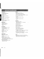
FMTuner
Audio
Frequency Range:
87.9 MHz to 107.9 MHz
Maximum Power Output:
200 W (50 W x 4 ch) (JEITA)
Usable Sensitivity:
11 dBf
Continuous Average Power Output:
16 W x 4, into 4 n, 20 Hz to 20 kHz, 1a/aTH 0
50dB Quieting Sensitivity:
17 dBf
Bass Control Action (30 Hz):
±13 dB
Alternate Channel Selectivity:
75 dB
Treble Control Action (10kHz):
±10 dB
Stereo Separation (1 kHz):
35 dB
Line Output Level (CD 1kHz):
1.8 V
Frequency Response (±3 dB):
30 Hz to 15 kHz
General
AM Tuner
Frequency Range:
530 kHz to 1710kHz
Usable Sensitivity:
25 j1V
CD Player
Frequency Response (±1 dB):
10Hz to 20 kHz
Signal to Noise Ratio (1 kHz):
100 dB
Dynamic Range (1 kHz):
95 dB
Harmonic Distortion:
0.01 0/0
Power Supply Voltage:
14.4 V DC (10.8 to 15.6 V allowable),
negative ground
Current Consumption:
Less than 15 A
Speaker Impedance:
4 Q (4 Q to 8 Q allowable)
Weight / Source unit:
5.7 lb. (2.6 kg)
Weight / Remote control unit:
1 oz. (30 g) (including battery)
Dimensions / Source unit:
7/1 (Width) x 3-15/16/1 (Height) x 6-1/8/1 (Depth)
[178 (W) x 100 (H) x 155 (D) mm]
Dimensions / Remote control unit:
1-3/4/1 (Width) x 4-5/16/1 (Height) x 1 -1/8/1 (Depth)
[44 (W) x 110 (H) x 27 (D) mm]
Tape Deck
Wow & Flutter (WRMS):
0.06 0/0
Channel Separation (1 kHz):
45 dB
Frequency Response (±3 dB)
120/-1s (normal): 30 Hz to 18 kHz
70/-1s (Cr02,FeCr, Metal): 30 Hz to 20 kHz
Signal to Noise Ratio
70/-1s (Cr02 FeCr, Metal): 58 dB
Dolby B NFL 67dB
28
ADZ625
Notes:
• Specifications comply with JEITA Standards.
• Specifications and design are subject to change
without notice for further improvement.
English
Press the TAPE EJECT button
before using this unit for the first time.
French
Appuyer sur la touche d'ejection
(TAPE EJECT) avant
d1utiliser cette unite.
Spanish
Antes de utilizar esta unidad,
presione el boton de eyeccion
(TAPE EJECT)
Chinese
iim*mtii~~ ~~;tct1rf
TAPE EJECT tJtmf~~ ltiiJijfmo
285-1888-00
Clarion Co., Ltd.
2001/11 (A·C)
All Rights ReseNed. Copyright © 2001: Clarion Co., Ltd.
Printed in China! Imrnmi) en Chine! Inpreso en China! q,@IE~liill
PE-2495B
280-7740-00
Printed in China / impnme au Chine / ImpresQ en China / 1±<POOfPlJIJ 1999/11 (W.C) 284-9114-00
InstaliationlWire Connection Guide
Gufa de installaci6n/conexi6n de cables
Clarion
BID
...
-1 . BEFORE STARTING I
RATIFS I ANTES DE COMENZAR 11f~tif1=zm
Cet
voitures
negative.
1. This set is exclusively for use in cars with a
negative ground 12 V power supply.
2. Read these instructions carefully.
3. Be sure to disconnect the battery " 8 " terminal
before starting. This is to prevent short circuits
during installation. (Figure 1)
est concu exclusivement
!'alimentation est de 12 V
les
masse
1. Esta unidad ha sido disenada para utilizarse
exclusivamente en autom6viles con fuente de
alimentaci6n de 12 V, Y negativo amasa.
2. Lea cuidadosamente estas instrucciones.
3. Antes de comenzar la instalaci6n, cerci6rese de
Veuillez lire attentivement ces instructions.
3. Veillez
deb rancher la borne
batterie avant d'installer I'''l"ln;;rpil
court..circuil. (Figure 1)
1.4:~ fMJi. ffl
y Fli jJ.~Ut! lli -;Jg 12 V ,ffl. f& ~ 1t1!.i¥J $ !*J
0
2. j;i'i1H!Ilr~~*iM~Jj~o
3. *~I1t*ftJltr, j;i'iTiffliJ..BI~*'I'Flijtl!,i¥J "(-',)" tit i!~
-;Jg n,;7ll:1'E't(~4' ~:tHIT~o
(rn 1 )
desconectar el terminal" 8 " de la baterfa. Esto es
para evitar cortocircuitos durante la instalaci6n.
(Figura 1)
Car battery
BaUerle de voilure
Bateria del autom6vil
i't$f;f~i1!l
Figure 1 / Figure 1 / Figura 1 / IE 1
BID
...
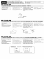
-2. CAUTIONS ON INSTALLATION /
/ PRECAUCIONES PARA LA INSTALACION / ~~a<Jj!.~I9i
:1"\1"'11""'"
Avant cle commencer I'installation cle I'apparei!
pilote, preparez toutes les pieces necessaires.
1. Prepare all articles necessary for installing the
source unit before starting.
a I'horizontale, a un angle maxi·
2 Installez
2. Install the unit within 30° of the horizontal plane.
mum de
(Figure 2)
3. If you have to do any work on the car body, such as
drilling holes, consult your car dealer beforehand.
4. Use the enclosed screws for installation. Using
other screws can cause damage. (Figure 3)
2)
3. Si vous devez effectuer des travaux sur la
carrosserie, par exemple percer des trollS,
consu!tez vOlre concessionnalre auto aupalavanL
4
Utilisez les vis fournies pour !'installation.
Lutilisalion de toute autre vis peut causer des
dommages. (Figure 3)
1. Antes de comenzar la instalaci6n, prepare todos
los elementos necesarios para instalar la unidad
fuente.
2. Instale la unidad con un angulo de 30° sobre el
plano horizontal. (Figura 2)
3. Si tiene que realizar cualquier trabajo en la
carrocerfa, como taladrado de orificios, etc.,
consulte al proveedor de su autom6vII.
]. 't('fgJltrw:iitiffi]fll't(~i:tJLEJTfIfi'B~!Io/Jr\1lo
2. fft 14' J'it: t1Ii ':k:'fg Jjj(; 1::] ;KIf iii Jjj(; 30 IJt X Jrlo (/J/ 2)
3.
PIi*~tE'ifpt~.t:iZt1TJ',\Jdt,
i3<J 1"1:'if B~ ff1j 1!f jfjf i?f i.~L
ttplit~1L':,:~~,
i:i'i(.i)f~
4. 1<''fg HJ i:f'f f'1! ffl "ft frJt~ {ft i¥J ~ i'~. f'1! jllyt '8 i¥J ~ i'f: PI ~~
0tBHf 4'>:fJL ( 003 )
0
4. Utilice
los tornillos suministrados para la
instalaci6n. La utilizaci6n de otros tornillos podrfa
resultar en danos. (Figura 3)
Chassis / Chassis / Chasis !til#!
1- -
-
Chassis / Chassis / Chasis / -IJtflJ
-
,
,
I
I
,
Max. 5/16"(8 mm)
~ - - - Max. 5/16"(8 mm)
Max. 5/16"(8 mm)
MA 5/16" 8 mm)
Figure 2/ Figure 2/ Figura 2/ IE 2
BID
Figure 3/ Figure 3/ Figura 3/IE 3
...
-3. INSTALLING THE SOURCE UNIT /"u"""
This unit is designed for fixed installation in the dashboard.
Cet
tableau
1. When installing the source unit in NISSAN vehicles,
use the parts attached to the unit and follow the
instructions in Figure 4.
I.
INSTALACION DE LA UNlOAD FUENTE 13::*JHr-J~~
ost conyu pour otro installc') dans !e
boreJ.
Esta unidad ha sido disenada para instalarse fijada al
tablero de instrumentos.
vous instaliez I'apparell pilote dans un vehicule
NISSAN. utilisez !es pieces attacl1ees I'oppareli
et suivez les Instnlclions de la figule
1. Cuando instale la unidad fuente en un autom6vil
NISSAN, utilice las piezas suministradas con la
unidad, y siga las instrucciones de la Figura 4.
Si vous inslallez
-fOYOIA (Figure
v6hicu!e el suivez
When installing the source unit in TOYOTA vehicles
(Figure 5), use the parts attached to the vehicle and
follow the instructions in Figure 5.
dans un vel1lcule
!es pieces allachees
instructions de !a figure 5
2. Wire as shown in Section 6.
2. HacconJez comme indiqu6 dans Ie parawaphe 6.
3. Reassemble and secure the unit in the dashboard
and set the face panel and center panel.
'l
Montez et fixez I'appal eil dans to talliew I de hOlT]
posez Ie panneau avant et Ie pannoau central
Mounting Screw Holes
Side View of the Source Unit
Orifices de montage
Vue !alem!o
r
Cuando instale la unidad fuente en un autom6vil
TOYOTA (Figura 5), utilice las piezas fijadas al
autom6vil y siga las instrucciones de la Figura 5.
2. Conecte los cables como se muestra en la Secci6n 6.
3. Ensamble y asegure la unidad al tablero de
instrumentos, y coloque el panel frontal y el panel
«entral.
Orificios para los tornillos de montaje
Vista lateral de la unidad fuente
NlSSAN \ Ll
)
i\Jf'·[I~!iJiR{'f~TL
0
0
2. J't(~ 6 l'iIliJf7f,*j~t~"
J i fJf <idl~()('& tfJi j'll<JHft cIf {'1! Z. 2p /i'iI. '!:C:liz iii tUIi
I}JfJi "
~~!IiJ~HL----,
:£tJU'tJlil1t:t\1fI
r
Screw holes for NISSAN vehicle
Orifices pour un vehioute NISSAN
Orificios para tomillos para un autom6vil NISSAN
]. l'r: N1SSAN ( EJ F) ib($.t1<''fgs;J, fi'if'1!ffl :i:fJlfi]frtji
If] 111m cIf j]! WHfJ 4 JiJr 7j~ i¥J JI1 iJ I
tETOYOTA ($[BJ 1"1:$ (005) .t':lC'fgsj, i'i'if'1!Jf
HJtJiJiwS0pHf4'clfjgHtHCf!5 JiJr7]~S<Jj!-iiJl
Screw holes for TOYOTA vehicle
Orifices pour un vehicule TOYOTA
, Orificios para tomillos para un autom6vil TOYOTA
!IFf TOYOTA ,1' W)
•
Installing the Source Unit in a NISSAN
Vehicle
•
II Installation de
un vehicule l\m);:',~I'&
Instalaci6n de la unidad fuente en un
autom6vil NISSAN
Note 2 / Remarque 2/ Nota 2 / it." 2
6-Double-sided tape
(Provided with the installation kit, sold separately)
6-Bando double face adll('Jsive
(Fourni avec Ie kit de montage, vencill sepan'Jrnent)
6-Cinta adhesiva por ambas caras
(Se suministra con ei juego de insta/aci6n, vendido aparte)
~
a
~r
o
A!5} ~ I
@'W~
J--,...~
o
8<
~':1<1
~ ~©
@
o ...
~
,~
6-Spacer (Provided with the installation kit, sold separately)
S-Elltretoi.ses..(F..o..u.mi avec.. Ie kit de montage. vendu separernent)
su.
. . con el juego de instalaci6n, vendido aparte)
() i±~ h (!lft#Hl'J J<'f< r H, -7J f~,;- )
6-Sefa~ad~~ (~~ mini~t~a
~
~
~
J~
"'-.... 0
(;r~
~
I
r--
~
6-Flat head screw (M5 x 8)
(attached to the source unit)
6-Vis a tete plate (M5 / 8)
(sur I'apparoll pilote)
6-Tomillos de cabeza plana (M5 x 8)
(.fijados a la unidad fuente)
(,
rM5x8;
,;
V'''~
Finisher (Provided with the installation kit, sold separately) (Note 1)
Finisseur (Foumi avec Ie kit de montage. vendu separemenl) (Remarglle 1)
Placa de adomo (Se suministra con el juego de instalaci6n, vendido aparte) (Nota 1)
lj!ij it': 5'1- '~.
(~Id
:r,J t~- )
;n;; 09 'Ii. '1*
'~
\
~
')
Mounting bracket (Metal plate)
(plaque rnelallique)
Soporte de montaje (Placa metalica)
fJLtJ~ l :ir;H~f!i)
Figure 4 / Figure 4 / Figura 4 /
~4
Note 1:
Remarque 1:
Nota 1:
;:t,g 1 :
Position the face panel with its wide edge at the
bottom. Fit the edge into the groove of the source unit.
Posez Ie
avant avec Ie bmd Ie plus
dirige vers
bas. Inserez Ie bard dans la rail1lilO
I'appareil pilote.
Coloque el panel frontal con su borde ancho en la
parte inferior. Fije el borde en la unidad fuente.
'v:JmifJt !)z
Note 2:
Peel off the exfoliation sheet from the tape and attach
the spacer to the source unit.
•
Installing the Source Unit in a TOYOTA
Vehicle
Install by using parts attached to the vehicle.
(Screws marked
are attached to the vehicle.)
*
Remarque2:
Enlevez la feuille de protection de la lJande et collez
I'entretolse sur I'apparell pilote.
rell
un
dans
Nota 2:
iE§.2 :
Despegue el papel de exfoliaci6n de la cinta y fije el
separador a la unidad fuente.
.Ta*~~
•
vel1iclule
Iinstaller avec les
vis indiquees par
l~lt}~JJtt\l5$5i'~,
••, ~m~~±mffi~.
1£ TOYOTA
Instalaci6n de la unidad fuente en un
autom6vil TOYOTA
($fE) )9:;$J:.$:~±.m
mffl~*~~*~B#~.. (~~*%~.~.~*
Instalaci6n de la unidad utilizando las piezas
fijadas al autom6vil. (Los tornillos marcados con
estan fijados al autom6vil.)
tlxees au veilicule (I es
sont fixees au veilicule)
"4i;l1;JlllffiW'A±tJLtJL5trJ'J{£u,
F>!t*l'tg. )
*
8-Hexagon screw (M5 x 8)
(attached to the source unit)
'-
Center Panel (Note 3)
Panneau central (Remargue 3)
Panel central (Nota 3)
rj-1iJt Wi TIi. (
~ !
Mounting bracket (Metal plate)
Etriers (plaque metailique)
Soporte de montaje (Placa metalica)
tJL tlM ( _~;: !,~f!:{ 1
Figure 5 / Figure 5/ Figura 5 / ~ 5
Note 3:
Remarque 3:
Nota 3:
i:t,g J :
Some panel openings are too small for the unit
depending on the vehicle type and model. In such a
case, trim the upper and lower sides of the panel frame
by about 1/64" to 3/64" (0.5 to 1.5 mm) so the unit can
be inserted smoothly.
Selol1 Ie modele et Ie type de ~~~:~~:r~;'lles UlivsrlUiSS
sonl parfois
Oans ce
Iss
du pamluau
,r~h'''''''' 1/64"
a 1
mill) prllil '1110
l'aplx1reil pliisse etre
sans probleme.
Algunas aberturas del panel son demasiado pequenas
para la unidad dependiendo del tipo y modelo de
autom6vik En tal caso, recorte las partes superior e
inferior del marco del panel de 1/64" a 3/64" (0,5 a 1,5
mm) a fin de poder insertar facilmente la unidad.
Ilj(jiCC-$.JJi} fj (0 "F iii] ,
Note 4:
Remarque 4:
Nota 4:
If a hook on the installation bracket interferes with the
unit, bend and flatten it with a nipper or similar tool.
Si un cmc!lel elu
d'il1stallaliun
rabattez· COll1pletE,1ll13nt avec line
similalre.
a
I'appareii.
ou lill Lu:ii
Typical Mounting Brackets / Exernples de
Si un g<l.ncho del soporte de montaje interfiere en la
unidad, d6blelo y aplanelo con unos alicates u otra
herramienta similar.
1"1' 'tl'i Jj; F.
fJL oj
T .:l::tJLITiJ i"f:k/L .i!
O. 5 fill. 5mm, f~ lit .:l::
J;tJl'~I~1 tJ~D/j}fJi. ~1
!~ ii ftITil;i (n fiji ill jfj] IrE ill t'~
W~i 'f1J(1']jfti A.
tEi!!4 :
i!lL\flI!L ',1'J, I
D~ flJ
T JvJ fig '!<k~. iff f~ HHtt T ~ ?it!!!) fig J,jj, 3f 1'I
"8,
de I'elder / Soprtes para montaje Upico / ~!l'HfJtJl1¥1
Affix the screws to the. marks.
Inserez les vis dans les orifices indiquBs pa!" -~
Fije los tomillos a las marcas •.
io!iJ Jt
•
Example 1:
Exemple t·
Ejemplo 1:
Example 2:
Exemple 2,
Ejemplo 2:
Example 3:
Exempie 3:
Ejemplo 3:
i9IFi"1
i9H2:
i9<Fi"3 :
Vehicles other than NISSAN and
TOYOTA
II Vehicules d'une autre marquE! que
NISSAN et
In some cases the center panel may require modification. (Trimming, filing, etc.)
Dalls cCitains
10 pannoau centrai cJovm 8111111
qiJekJ,iJos rIIc)dific8Itlons. (Ajustemont, limago, ok.)
• Removing the Source Unit
When the soure unit is to be removed, disassemble
it in the reverse of the order in "INSTALLING THE
SOURCE UNIT".
• Retrait de l'al:108reil
SI vous devez onlevel I'"rm"rc.i!
cn
1.1 I'inverse
L'AI"Pfl\fiE Ii. PILOTE"
•
•
fij; ~t.~J_!YJ~'~5tA
Autom6viles que no sean NISSAN ni
TOYOTA
En algunos casos, el panel frontal puede requerir
modificaci6n. (Recorte, Iimado, etc.)
• Desmontaje de la unidad fuente
demullic,?·lo
i.ATION
Cuando desee desmontar la unidad fuerJte, hagalo
en sentido inverso al de "INSTALACION DE LA
UNlOAD FUENTE".
•
:X;j"f-NISSPN
(SF)
~IHOYOTA ($fE)
9HflR;$
J;t~m%T, ~*ITiJfi.4.~. (.~,m~.)
Z
.. --4.
CAUTIONS ON WIRING I PRECAUTIONS
1. Be sure to turn the power off before wiring.
2. Be particularly careful where you route the wires.
Keep them well away from the engine and exhaust
pipe, etc. Heat may damage the wires.
3. If the fuse should blow, check to see if the wiring is
correct.
If it is, replace the fuse with a new one with the
same amperage rating as the original.
4. To replace the fuse, release the catch on the source
unit side, remove the old fuse and insert the new
one. (Figure 6)
Note: There are various types of fuse holder. Do
not let the battery side touch other metal
parts.
PRECAUCIONES PARA LA CONEXION DE CABLES I tl~~j1.*I9J
SUJET DES
1. Antes de conectar los cables, cerciorese de
desconectar la alimentacion.
I. Veiliez
arreler Ie moteur avant de fcme
connexlons.
2. Tenga especial culdado cuando enrute los cables.
Falles Ires attention Oll vous acheminez les fils.
Ne les faites
passer
du moteur, du
etc.
chaleur pourralt
endommager.
Mantengalos alejados del motor, el tubo de escape,
etc. EI calor podria danar los cables.
3. Si se quema un fusible, compruebe si la conexlon
de los cables es correcta.
Si 10 es, reemplace el fusible pOI' otro nuevo con el
mismo amperaje que el del original.
3. SI Ie fusible saute. verifiez sl Ie
SI ce n'est
Ie cas. rennpl<3cEiz
neuf, de
ampere que
4. Pour
cOte de
Inserez-en un
Ie fusible. ouvrez Ie vermu sur Ie
enlevez Ie vleux lusible el
(Figure 6)
Remarque: II y a different
4.
I. ji<r~BHPififfJiJ~iIIj(BtrJ lJ:JT
2.
1
4.
Para reemplazar el fusible, abra el seguro de la
parte lateral de la unidad fuente, extralga el fusible
quemado e inserte el nuevo. (Figura 6)
:ffir~Bt:!t:lt~/J\;c"o
l('jjjr~L ¥JtMj;,F\T·r~,
0
\1'rxE'Zitti&\:ⅈljtJl,
t1F{i,'1'f~o
••
~m~~tt.~, .~
~~~£•. ~m.~
.~~k~~*~~*$~~~~~~tt.
£.,
i.E ~ 1Ji!: I;~ tt lit, 7t tJJ F.±: fJl fl!~ 00 1'19 tiJi Jt, 1f;u±J IB1'19
!Ji!:[;{,[tt, JJX )dlfl(j91jit~~tt. ([!fJ 6 )
~.:~~tt*~W~#
tt f!jgUv. JlJH2!iI*.
.• ~.k~~~ttm~
Nota: Existen varios tipos de portafusibles. No
permita que el terminal del lado de la bateria
toque otras partes metalicas.
La
borne du
ne dolt pas
toucher d'autres pieces metalilques.
Fuse (15 A)
Fusible (15 A)
Fusible (15 A)
Npi,tii: (15 A)
Fuse holder
Porte, fusible
Portafusible
r~~ I;~t #. ,%
Figure 6/ Figure 6/ Figura 6/ ~ 6
•
CeNET input
Orient the GeNET cable in the direction shown in
Figure 7 and insert it until it is locked in position.
Wire the GeNET cable so that there is minimal
tension in the cable, and the connection part will
not come off.
To remove the GeNET cable, pull it by lightly
grasping the slide cap in your fingers.
To extend the GeNET cable, use either the GeNET
extension cable 2.5 m, GeNET extension cable 0.6 m,
or V-adapter 1.5 m (they are separately sold.). For
more information, consult your store of purchase.
mID
Entree CeNET
•
Ie cable CeNET dans Ie sens Indique
la
Fig
et insorez-Ie jusqu'a ce qu'i! soit verrouillo en
position.
Entrada CeNET
ait une
de
• Gonecte el cable GeNET de forma que reciba la
minima tension y no se desprenda la parte de
conexlon.
tirez dessus en
coulissant entre
• Para desconectar el cable GeNET, tire Iigeramente
de el sujetando IIgeramente la tapa deslizable con
sus dedos.
utilisez so it Ie
• Pour rallonger Ie cable
cable de rallonge CeNET de
salt Ie ciible
de
CeNET de
Y
de 1
vendus
Pour de plus
consultez volre rnagasin.
• Para prolongar el cable GeNET, utilice un cable
prolongador GeNET de 2,5 m, un cable prolongador
GeNET de 0,6 m, 0 un adaptador en Y de 1,5 m
(vendidos aparte). Para mas informacion, consulte a
su proveedor.
qu'll
• Achemiller Ie cable CeNET de
que la
tension minimale sur Ie cable
raccordement ne se detache pas.
• Pour retirer Ie cable
saislssant dolicatement Ie
vos doigts.
N
~ ::I,
Slide cap
Cap\lchon coutissant
~
mI~
CeNb:T
C:cNET~A
CeNETcable
(provided with the CD changer or MD changer)
Callie CeNET
(fourni avec Ie cllal1geur CO ou Ie cllangeur MO)
Cable CeNET
(suministrado con el cambiador de discos
compactos 0 de minidiscos)
CcNLI'
( FlU Cil
Figure 7 I Figure '7 / Figura 7 /
~
'Ill w,ih~·tJl"HIfi')
7
SYSTEMES I EJEMPLOS DE SISTEMAS I *~f9Jj*~ft
CD
CD 2 DIN combi
W GeNET extension cable
®
W
®
®
([)
G.:' Gombinacion de 2 DIN
(?
Gable prolongador GeNET
V-adapter
6-disc MD changer
@
r!Ii
Adaptador en Y
Gambiador de 6 minidiscos
6-disc GD changer
Front speaker
Rear speaker
~
(§!
Gambiador de 6 discos compactos
Altavoz delantero
iTI
Altavoz trasero
Enceinte arriere
~i"~r~k'J 1'i!~i"Jllm)J:ml:/J\,
'*
Entree CeNET
~
~i"JllJlti<{:Em'!H.fl:!ll'::ft~Zfi'il
~Jj l1:.i!tU~
5f!J5GlifL
lFfJF CaNET ~r1~lIt, fflTJ'lJfif1:ttrJ'milf,f[:ltibttlL
'Il,)'}!£-K CeNET ~i"Ata1, PI ~ffl2.5 CeNET 1t~~
i"~, 0.6 *CeNFrtt~:Jt~jj,H5
Y lliJmllc~~ (:ti)
'1M' 1ij mtJ) , It 'ti1f ilif ,n] mtJ rn 1&UU
~ Entrada CeNET
~
-5. SAMPLE SYSTEMS I EXEMPLES
fifm 7 JiJji~*1j' CcNET
;Eo
CoNET ;op"'
Tapa deslizable
fftmE
.. --
.GeNET~A
• Oriente el cable GeNET en el sentido mostrado en
la figura 7, e Insertelo hasta que quede bloqueado
en su posicion.
(j'
2 DIN trr
**
0
.. _-
-6. WIRE CONNECTIONS I CONNECTIQUE I CONEXION DE CABLES 11i~!
1. RCA Extension Cable
1. RCA IrJifttIifIt
1. Cable prolongador RCA
Notes:
• Do not remove the insulating cap of the RCA extension cable which is not going to be connected to
prevent it from short-circuit.
, Fix the RCA extension cable with insulating tape so
that the connection part is not going to be loose.
Remarques;
• No retirez
Isoiani elll cabie de
rallonge
s!
! ar:ce/dez pas, alin de ie
proiegor (:ontrc
o Fixez Ie
de rallonce Hell
i acc:;rclHi 1lent
ra\on quo 1a
To external amplifier /
Notas:
• No quite el tapon aislante del cable prolongador RCA
que no vaya a conectar a fin de evitar que provoque
un cortocircuito.
• Fije el cable prolongador RCA con cinta aislante para
que la parte de conexion no se afloje.
i!~:
?ijjJ ff ECA i! Jloi[[email protected]'i:]tI~f;''(,;'ii, l~ (1"B' J%Rt 1d:'!W],L
• J+1~i'of*#H\ljE RCA
!11'tJi<g-I'Jrf'LB,L
/ AI amplificador externo I
Red
Front Right
Avant IJro\t
Delantero derecho
Raja
Front Left
Avant
De/antero izquierdo
16-P!n connector
Con ector de 16 contactos
RCA pin cable rear output
Salida trasera del cable can clavijas RCA
RC,\ '::,"I'_r~I,;t~;!I:
Rear Right
/\1 ~!e!"e droit8
~~::Ze::asero
derecho
~~~~~!::::~::::~~~~~~====;:~~(===============r1
,E,~~~a,da~eNET
gaud12
Altavoz trasero Izquierdo
lID
I
....------ 16~Pin connector extension lead
('; 16
Cable prolongador del conector de 16 contactos
Entrada de antena
de alirnentacion)
Front Right
Avant [iml
Delantero derecho
' - - - - - - - - - Connect it to the car power supply terrninal for illumination.
iliiSC
de
vuitwc
para iluminaci6n.
e Gray/Black wire
e Alambre gris/negro
E±)
Purple wire - _ _ _ _ _ Connect to cellular phone mute lead
IV Alambre purpura
8¥f0.{'!J~
Conectelo al conductor de silenciamiento del telefono celular.
e Purple/Black wire
e Green/Black wire
15 A
'----[=:::1---Fuse
or
ou
o
Regardless of whether the ignition is turned on or off, connect to
the power source terminal to which 15A or more of current can
be supplied,
in r:lc
Fusible
Independienternente de la posicion, ON y OFF, de la lIave de encendido,
real ice la conexi6n a un terminal de la fuente de alimentaci6n que pueda
suministrar 15A 0 mas.
Red wire (Power
rOl!qc ifi; ,'-niinlmlia1,,,"')
Alambre rajo (cable de alimentaci6n)
Connect to the main memory cable.
de rnE'::n1uire priric!pale
Conecte al cable de la memoria principal.
{
' - - - - - - - - - - Accessory +12 V
t\ccessnile \
\i
Accesorio + 12 V
+12 V
2-Speaker
Svsl8rne
Sistema con 2 altavoces
Blue/White wire (Amplifier turn-on lead)
'iii
!!'!Ss
te"s'on ielcc",,,,,,,,,,,,!,,,,,,,
Alarnbre raja (cable de alirnentacion)
'------IT~~~ Connect to remote turn-on lead of a~~,I:~~ier (0.5 A current max)
X
Not used,
Insulate each wire.
Black wife (Ground lead)
Alarnbre negro (conductor de tierra)
Conectelo a una parte metalica del chasis del vehiculo.
mm!I"'
-7.
_
GENERAL CAUTIONS I PRECAUTIONS
1. Do not open the case. There are no user serviceable parts inside. If you drop anything into the unit
during installation, consult your dealer or an authorized CLARION service center.
2. Use a soft, dry cloth to clean the case. Never use a
rough cloth, thinner, benzene or alcohol, etc. For
tough dirt, apply a little cold or warm water to a soft
cloth and wipe off the dirt gently.
ENERALES I PRECAUCIONES GENERALES I -~1:t~$!YJ
;\UC\1tJn piOCG no peLt hlP:;
VilUS laissez
I'apparell
1{JllllJCI
pClldanl
Icvcndcl!! ill! ,:11
(I; /IniON
2,
1. No abra la caja. En el interior no existe ninguna
pieza que pueda reparar el usuario.
Si cae algo dentro de la unidad durante la
instalacion, consulte a su proveedor 0 a un centro
de reparaciones autorizado por CLARION.
2. Para limpiar la caja, utilice un pano suave y seco. No
utilice nunca panos duros, diluidor de pintura,
bencina, alcohol, etc. Si la suciedad es dificil de
limpiar. humedezca ligeramente un pano suave en
agua frfa 0 calida y frote suavemente la parte sucia.
1,
:iF 'JJit r IF fiLtH, tJltnl),])il 1~ ill; IH}O i;J! m(1'0 iII> f'l
0
~*~~~MN~, 4~~~~mm, ~~~~m
:+i lilT ~'Y CLIRIONtH{(i!J III:!. fj-'j',C},RLVL
,
mmmm&~mm~~~,+~~m~~.~~~,
_ iMfi'\ij'., izUl,JUllHfHRJ,rj1Jj, "j1'lHHIi liWf.;-i'r
If:;' 'f. jf,HTl ,
;Y;U!(Q~;IiIr;K,
clarion
WAR RAN T Y I N FOR MAT ION
D:mmPRODUCT
TEAR THIS PAGE OFF AND KEEP IT WITH YOUR RECEIPT!
REGISTRATION
CAROl
Thank you for selecting a high-quality product from Clarion. We hope you are completely satisfied
with your purchase. We'd like to help serve you better by finding out more about your reasons for
choosing Clarion. Please take a few moments to fill out the registration information on this card and
answer a few questions about yourself and your product. Then, return the card to Clarion within 10
days of purchase. Your answers will be kept strictly confidential. We appreciate your response!
What is your age? (Optional) 1
II
Are there any children in your household?
10 Yes
20No
If yes, please specify age range:
4013-16
5017 & up
iii
In Canada, place the card in an envelope and mail to:
Clarion Canada, Inc.• Warranty Service Center, 2239 Winston Park Drive, Oakville, Ontario L6H 5R1.
. . 0 Mr. 0 Ms. 0 Mrs. 0 Miss
...
...'"
...
This product is warranted against all defects in material workmanship for a period of
one year from the date of original purchase. The conditions of this warranty and the
extent of the responsibility of Clarion Corporation under this warranty are as follows:
"C
-
PRODUCT. INFORMATION ABOUT CLARION AUTHORIZED WARRANTY SERVICE CENTERS MAY
ALSO BE OBTAINED BY CONTACTING OR WRITING CLARION CORPORATION AT THE ADDRESS
LISTED ON THE FRONT OF THIS CARD.
2. This warranty will become void if service performed by anyone other than an approved Clarion
Warranty Service Center results in damage to product.
3. This warranty does not apply to any product which has been subject to misuse, neglect or
accident, or which has had the serial number altered, defaced or removed, or which has been
connected, installed, adjusted or repaired, other than in accordance with the instructions
furnished by Clarion Corporation.
4. This warranty does not cover car static or other electrical interferences, tape head cleaning or
adjustments, or labor costs for the removal or reinstallation of the unit for repair.
5. The sole responsibility of Clarion Corporation under this Warranty shall be limited to the repair or
replacement thereof, at the sole discretion of Clarion Corporation.
6. If it becomes necessary to send the product or any defective part to Clarion Corporation or an
authorized warranty service station, the product must be shipped in its original carton or
equivalent carton, fully insured, with shipping charges prepaid. Clarion Corporation will not
assume any responsibility for any loss or damage incurred in shipping.
7. ALL IMPLIED WARRANTIES EXCEPT TO THE EXTENT PROHIBITED BY APPLICABLE LAW SHALL
HAVE NO GREATER DURATION THAN THE WARRANTY PERIOD SET FORTH ABOVE. UNDER NO
CIRCUMSTANCES SHALL CLARION CORPORATION BE LIABLE FOR ANY LOSS OR DAMAGE, DIRECT
OR CONSEQUENTIAL, ARISING OUT OF THE USE OR INABILITY TO USE THE PRODUCT. BECAUSE
SOME STATES DO NOT ALLOW LIMITATIONS ON HOW LONG AN IMPLIED WARRANTY LASTS OR
EXCLUSIONS OR LIMITATIONS OF INCIDENTAL OR CONSEQUENTIAL DAMAGES, THE ABOVE
LIMITATIONS OR EXCLUSIONS MAY NOT APPLY TO YOU.
8. THIS WARRANTY GIVES YOU SPECIFIC LEGAL RIGHTS, AND YOU MAY ALSO HAVE OTHER RIGHTS
WHICH VARY FROM STATE TO STATE.
9. Should you have any difficulties with the performance of this product during warranty, or with any
Clarion authorized service centers, you may contact the Clarion National Service Managers at the
address listed on the front of this card or call 1-800-GO-CLARION for a listing of Authorized
Warranty Service Centers in your area.
281-0607-00
II
Q
Q
...
:::>
Q.
30 1 - 12
What is the highest level of education you have completed?
10 Some High School
40 Completed College
20 High School Graduate
50 Some Graduate School
30 Some College
60 Completed Graduate School
70 Vocation/Technical School
What best describes your primary occupation?
10 Professional/Technical
Q
...
2,;;;,0;;;...Ma;..rr..,,;ie,;;,d_..;.3,;;;0;;.S;,;;in,;,;;g;..le
C
'"
~
1. PROOF OF DATE OF PURCHASE WILL BE REQUIRED FOR WARRANTY SERVICE OF THIS
D:]....__M_a_ri_ta_I_Sta_tu_S?_.;",(O;",Pt_io_na..,;I)_ _
•
50 Clerical/Service Worker
90 Homemaker
20 Upper ManagemenVExecutive
60 Tradesman/Machine Operator/Laborer
100 Student
30 Middle Management
70 Self-Employed/Business Owner
11
40
80 Food Service
120 Other
Sales/Marketing
0 Retired
...
E
. . What is your annual household income? (Optional)
"C
...
C
C
'.' I
Q
en
"C
...
: II
•
<>
What Clarion product did you purchase?
CCI
en
Multimedia
Car Audio
'"
.c
10 Color LCD Display/Control Unit
80 AM/FM Cassette
20 Color LCD Display
90 AM/FM CD Player
..
30 Cellular Telephone
'<
Q
C
E
Q
c.>
'"
'"
(')
II
10 Under $10,000
40 $30,000 - $39,999
70 $60,000 - $69,999
100 $90,000 - $99,999
20 $10,000 - $19,999
50 $40.000 - $49,999
80 $70,000 - $79,999
11 0 $100,000 and over
3D $20,000 - $29,999
60 $50,000 - $59,999
90 $80,000 - $89,999
Which factors influenced you the MOST in choosing this Clarion Product?
Group A (Please check two)
70 Recommended by Store Salesp~rson
10 Newspaper Advertisement
10 0 AM/FM Cassette/CD Player
Comm~~ial
40 Voice-Activated Navigation System
11 0 CD Changer
20 TV
50 Video Cassette Player
120 Equalizer/DSP Processor Module
30 Radio Commercial
60 TV Tuner
130 Amplifier
70 Rear Vision Camera
14 0 Speakers
80 On-line Information
90 Clarion Web Site
40 Magazine Advertisement
100 Store Display
50 Recommended by Friend/Family
11 0 Special Promotion
60 Clarion Name/Reputation
120 Other
Group B (Please check two)
II
13
What is the name of the store where you purchased this product?
0 Warranty
140 Price
iii
150 Quality/Reliability
17 0
160 Features
18 0 Ease of Operation
Appearance/Design
190 Other
What type of music do you listen to most often? (Please check one)
10 Rock
40 Pop
70 Rap
100 New Age
20 Jazz
50 Country
8 0 Rhythm & Blues
11 0 Easy Listening
30 Blues
6 0 Classical
90 Reggae
12
0 Alternative
Which of the following products/services do you own or intend to buy within the next 18 months?
Own
Intend to buy
Own
Intend to buy
Satellite System/Service
170
240
Cellular Telephone
180
250
110
Pager
190
260
40
120
Call Waiting
200
270
Computer Speakers
50
130
Karaoke
210
280
Color Printer
60
140
Vehicle Navigation System
220
290
Modem
70
150
Vehicle Security System
230
300
Large Screen TV (35" or larger)
80
160
Home Desktop PC
10
90
Laptop Computer
20
100
Color Monitor
3D
CD-ROM
Is this your first Clarion purchase?
10 1st purchase
20 2nd purchase
clarion
CAR AUDIO {;} BEYOND
Product Registration
30 3rd or more
:- III What type of computer do you own?
'"
.,
-
10 IBM PC or Clone
CD
~
o
'"
~
o
0 Macintosh or Clone
for USA and Canada only
3D Do Not Own
Which on-line service/network do you subscribe to?
10 America Online
CD
0.
2
2
0 CompuServe
3D GEnie
40MSN
70 Other
50 Internet
8
0 Do not have service/access
IMPORTANT:
60 Prodigy
:::l
.,
-
: :T
CD
.,
0.
CD
c
c
z
c
...
...
en
:r>
."
....
m
ADX SERIES, PRO VIDEO & PRO AUDIO WARRANTY INFORMATION
Clarion offers two-year warranty coverage on ADX Series, Pro Video, and Pro Audio products (excluding
speakers) ONLY if the product is installed at the same location where purchased. If not installed by the
authorized dealer. one-year warranty coverage is provided.
To obtain two-year warranty coverage on your Clarion ADX Series, Pro Video, or Pro Audio product,
excluding speakers, complete this section in full and return it along with a copy of your receipt and
the attached product registration information in an envelope addressed to:
Clarion Sales Corporation
P.O. Box 863
Brea, CA 92822-0863
1. Detach this section of the card and keep it with your records.
n
o
2. Retain your sales receipt to validate warranty service.
~
a
o~z
3. If you purchased a Clarion ADX Series, Pro Video or Pro Audio
product, be sure to complete the box on the last page of this form.
Inforrtlation on Clarion authorized Warranty Centers
may be obtained by writing Clarion Corporation at the address below
or by calling
1-800-GO-CLARION.
~
S
~
~
'i.
§:
'Xi
8
::I:
~
I-
s
JJ
"-
~
"1
;:2
~
,;
~
m P
iii
/;;
U>
m U> "j;;
a
1il
In USA:
Clarion Sales Corporation
Warranty Service Center
661 West Redondo Beach Blvd.
Gardena, CA 90247
(310) 327-9100
<;:
"
In Canada
Clarion Canada, Inc.
Warranty Service Center
2239 Winston Park Drive
Oakville, Ontario L6H 5R1
(905) 829-4600
www.clarionmultimedia.com