1
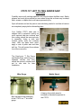
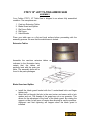
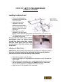
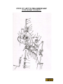
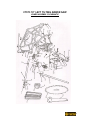
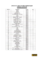
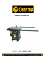
OWNER’S MANUAL CT073 – 10” TABLE SAW CT073 10” LEFT TILTING ARBOR SAW INDEX GENERAL SAFETY INSTRUCTIONS SPECIFIC SAFETY INSTRUCTIONS CT073 Features Unpacking Assembly Extension Tables Blade Guard & Splitter Installing Blade Guard Adjusting Blade Guard Adjusting Blade Guard, Continued Arbor Extension Blade Installation Hand Wheels Blade Alignment Adjusting Saw Table Adjusting Saw table, Continued Table Insert Rip Fence Assembly Rip Fence Assembly, Continued Rip Fence Adjustments Electrical Diagram & Wiring Electrical Diagram & Wiring Continued Operation Blade Height Adjustment Blade Tilt Adjustment Mitre Gauge Adjustment Maintenance Mitre Gauge Schematic Drawing & Parts List Blade Guard Schematic Drawing & Parts List Upper Assembly Schematic Drawing Lower Assembly Schematic Drawing Assembly Parts List Assembly Parts list, Continued Cabinet Schematic Drawing Cabinet Parts List Fence Schematic Drawing Fence Parts List Warranty Page 3 Page 4 Page 5 Page 6 Page 7 Page 7 Page 7 Page 8 Page 8 Page 9 Page 9 Page 9 Page 10 Page 10 Page 10 Page 11 Page 11 Page 11 Page 12 Page 12 Page 13 Page 14 Page 15 Page 15 Page 15 Page 16 Page 17 Page 18 Page 19 Page 20 Page 21 Page 22 Page 23 Page 24 Page 25 Page 26 Page 27 2 GENERAL SAFETY INSTRUCTIONS EXTREME CAUTION SHOULD BE USED IN OPERATING ALL POWER TOOLS. KNOW YOUR POWER TOOL, BE FAMILIAR WITH ITS OPERATION. READ THE OWNER’S MANUAL AND PRACTICE SAFE USAGE PROCEDURES AT ALL TIMES. CONNECT your machine ONLY to the matched and specified power source. WEAR SAFETY GLASSES, RESPIRATORS, HEARING PROTECTION and SAFETY SHOES when operating heavy machinery. Always wear safety glasses. DO NOT wear loose clothing or jewellery when operating machinery. A Safe Environment is important. Keep the area free of dust, dirt and other debris in the immediate vicinity of the machine. BE ALERT! Do Not Use prescription or other drugs that may affect your ability or judgement to safely use this machine. DISCONNECT the power source making other adjustments or repairs. NEVER leave an operating tool unattended. NEVER reach over the table when the tool is in operation. ALWAYS keep blades, knives or bits sharp and properly aligned. ALWAYS keep all safety guards in place and ensure their proper function. ALWAYS use push sticks and featherboards to safely feed your work through the machine. ALWAYS make sure that any tools used for adjustments are removed before operating the machine. ALWAYS secure your work with the appropriate clamps or vises. ALWAYS keep bystanders safely away while operating machinery. THINK SAFETY. WORK SAFELY. Never attempt a procedure if it does not feel safe or comfortable. 3 CRAFTEX CT073 LEFT TILTING ARBOR SAW SPECIFIC SAFETY INSTRUCTIONS NEVER attempt to remove jammed cutoff pieces until the saw blade has come to a full stop. NEVER use a saw blade that has a.) Missing carbide teeth, b.) Loose teeth, c.) Chipped or broken teeth. NEVER stand directly in line with the saw blade when feeding stock into the saw. NEVER allow visitors or helpers to stand in line with the saw blade. NEVER allow anyone to “assist” you by holding your workpiece at the outfeed end. NEVER attempt to cut stock “freehand”, always use the rip fence or mitre gauge. ALWAYS make sure that the rip fence is properly squared to the saw blade to prevent kickback. ALWAYS make sure that your saw is in a stable position. Cutting long, heavy stock may alter the stability of the CT073. In the event that this could be a regular circumstance, the saw should be bolted to the floor. ALWAYS be sure that the mobile base wheels are firmly locked before turning the saw on. ALWAYS use an outfeed table to support long pieces of stock. ALWAYS use a feather board and/or hold-downs to support your workpiece. ALWAYS turn the saw off in the event of a motor stall or blade jam before attempting to remove the stock. ALWAYS use only those accessories designed specifically for the CT073 table saw. 4 CRAFTEX CT073 LEFT TILTING ARBOR SAW FEATURES The Craftex CT073 Left Tilting Arbor Saw is a precision-built tool that will provide you with many years of excellent service. Motor – 3HP, 220v, single phase Blade Speed – 4,140 RPM’s. Triple ‘V’-belt drive. Cast-iron trunions. Sealed ball bearings. Precision ground cast-iron table top. Precision ground cast iron table extensions ‘T’-slot Mitre gauge. Magnetic power switch. Overall table size with extensions – 30” x 48”. Maximum depth of cut at 90 degrees – 3”. Maximum depth of cut at 45 degrees – 2 1/8” Shipping weight – 270kg. Includes a heavy-duty mobile base with wheel locks. ‘T’ type heavy-duty cam lever rip fence. Magnifying cursor lens on rip fence. Arbor extension included. Two push sticks included. 5 CT073 10” LEFT TILTING ARBOR SAW UNPACKING Carefully remove all packing materials and recycle where facilities exist. Safety glasses and work gloves should be worn when doing this as there may be sharp nails, screws or staples that could cause personal injury. Open all cartons and set the parts to one side being careful to see that all cartons are completely empty before discarding them. Your Craftex CT073 table saw is shipped with a protective coating on most exposed cast-iron surfaces and this coating should be removed prior to assembly. Using a cloth and mineral spirits, wipe the surfaces clean. After the parts have dried, apply a coat of paste wax and then buff dry. This will protect the surfaces from future corrosion. The Cam-Lever ‘T’ Rip Fence and Mobile Base will be found in separate cartons and they should be opened, checked and put to one side for later installation. Mitre Gauge Also included in the packaging of the CT073 is a ‘T’ slot mitre gauge. Mobile Stand A heavy-duty mobile stand is included as standard equipment in the CT073. 6 CT073 10” LEFT TILTING ARBOR SAW ASSEMBLY Your Craftex CT073, 10” Table Saw is shipped in an almost fully assembled condition. The exceptions are: 1. 2. 3. 4. 5. Cast-iron Extension Tables. Blade Guard and Splitter. Rip Fence Rails. Rip Fence. Hand Wheels. Place your table saw on a flat and level surface before proceeding with the assembly process. Be sure that the mobile base is locked. Extension Tables Assemble the cast-iron extension tables as indicated in the illustration being certain that the tables are perfectly level with the main saw table. The assembly bolts will be found in the parts packages. Blade Guard and Splitter Install the blade guard bracket with the 2 socket-head bolts and finger tighten only. Insert the rod through the hole in the rear trunion and secure with a lock washer and nut. The threads of the guard are cut on an eccentric. This allows for the adjustment of the back of the blade guard. By rotating the support rod the rod will move off centre thus allowing for various positions. Alignment and final tightening will happen when the blade guard is installed. 7 CT073 10” LEFT TILTING ARBOR SAW ASSEMBLY, CONTINUED Installing the Blade Guard Position the blade guard so that it points to the front of the saw table. Attach the front of the spreader to the front attachment bracket with a hex bolt and washer. Hand tighten to allow for further adjustment. Attach the rear of the spreader to the rear guide bracket. Fasten with the attachments bolt and washer. Hand tighten only. The blade guard is now installed but not useable at this point. Be sure that the blade guard and the anti-kickback pawls are spring loaded forcing them down to the table surface. Both the blade guard and the pawls should return to the table surface after being lifted. Adjusting the Blade Guard IMPORTANT: The spreader must always be parallel to the saw blade and in the center of the kerf made by the saw blade. Not doing so will interfere with the saw cut and cause an unsafe guard operation. Raise the saw blade to its full height. Adjust the tilt angle to 90 degrees and use a square to verify this and lock the tilt wheel. When adjusting the spreader, use a straight edge length-wise to be sure that the spreader is in fact trailing in the middle of the kerf. Additionally, be sure that the spreader is perpendicular to the saw table. Align the front of the spreader to the saw blade. 8 CT073 10” LEFT TILTING ARBOR SAW ASSEMBLY, CONTINUED Adjusting the Blade Guard, Continued To adjust the height of the front spreader, loosen the front attachment bolt and position the spreader up or down. The correct height will allow the guard to just touch the table surface. Align the rear of the spreader by turning the support rod on its eccentric. Turning the rod will in effect move the rear bracket left or right. After the spreader is lined up in the center of the kerf, tighten the rod hex nut securely. Note; it may be necessary to remove the saw blade to tighten the hex nut. Adjust the angle (90 degrees) of the spreader to the table by loosening the hex bolt. Rotate the rod bracket until the spreader is perpendicular to the saw table. Adjust the height of the rear spreader so that the top edge is parallel with the table by loosening the rear bolt attachment bolt. When completed, tighten all nuts and bolts. The blade guard should now be fully assembled and operational. However, be certain that all connections are secure and that the spreader is centered in the kerf and that the guard and pawls automatically return to the table surface. Arbor Extension To install the 1” o.d. x 3” long arbor extension generally used for dadoes, thread it into the arbor by hand in a counter-clockwise rotation. Secure the extension by inserting the 8mm hex wrench into the socket at the outboard end of it and tighten. The arbor itself is held in place with the blade spanner wrench. Place the spanner on the inside blade flange with the two prongs inserted into the two holes in the flange. Seat the arbor extension firmly but do not over-tighten. Reverse the above procedure for removal. Blade Installation Position your saw blade on the arbor so that the blade is flush against the inside of the arbor flange and with the teeth pointing towards the front of the table saw. Place the outside blade flange on the arbor with the hollow side against the saw blade edge. Secure the flange and blade with the arbor nut and hand tighten. Tighten the arbor nut with the spanner. 9 CT073 10” LEFT TILTING ARBOR SAW ASSEMBLY, CONTINUED Hand Wheels The blade elevation and blade tilt hand wheels are factory installed. The crank handles for these are found in the parts package and are simply screwed into the wheels in the threaded holes provided. Blade Alignment The Craftex CT073 Table Saw is shipped from the factory fully aligned so that the miter slots are parallel to the saw blade. However, shipping and rough handling may have affected this. It is suggested that this alignment be checked prior to operating the saw. A simple method of checking the alignment follows. Clamp a dowel to the front of the mitre gauge. Raise the saw blade and pick out a saw tooth on the front of the blade and set the dowel in front of the mitre gauge so that the dowel end just touches the edge of the saw tooth. Mark that tooth with a felt marker. Rotate the saw blade by hand to bring the marked tooth to the rear of the saw. Gauge this tooth with the dowel. If the tooth is in the same position, the blade is parallel to the miter slots and no further adjustments are required. Adjusting the Saw Table for Parallel Should an adjustment be required, proceed as follows: Loosen the hex head cap screws fastening the table to the sheet metal base cabinet. Carefully shift the table to position it so that the saw blade is parallel to the mitre gauge slots. 10 CT073 10” LEFT TILTING ARBOR SAW ASSMEBLY, CONTINUED Adjusting the Saw Table for Parallel, Continued The saw blade must also be centred within the table insert opening. Securely tighten the hex head cap screws. Table Insert The table blade insert is installed at the factory and should be level with the saw table. Should this not be the case however, remove it and invert it. You will find adjustment screws at the four corners of the insert. Adjust these in or out until the insert sits perfectly flush with the tabletop. Rip Fence Assembly The CT073 is equipped with one of the finest ‘T’ type rip fences available. This cam lever fence incorporates a Microadjustment and a Magnifying Cursor Lens for precision cutting. Install the front rail to the leading edge of the saw table using four pan-head screws and lock washers. Using a combination square, set the tail to 20mm. Use this measurement along the front of the saw tabletop so that the front rail sits 20mm below the tabletop. Tighten all the screws. Install the rear fence rail to the back edge of the saw table using four hex screws and lock washers. 11 CT073 10” LEFT TILTING ARBOR SAW ASSEMBLY, CONTINUED Rip Fence Assembly, Continued Use the combination square and set the tail to 12mm. Use this along the back surface so that the rear rail sits 12 mm below the table surface. Tighten all the screws. Attach the guide rail to the front rail with the six 6mm screws and lock washers. Rip Fence Adjustments To adjust the rip fence so that it is flush with the table saw surface, rotate one or both of the nylon screws to raise or lower the fence. The edge surfaces of the rip fence must be perpendicular to the table surface. Use a combination square for verification and adjust the nylon screws as required. To adjust the fence so that it is parallel to mitre slots, remove the fence and adjust one or both of the setscrews in the ‘T’. To adjust the clamping pressure of the cam lock, unlock the lever and remove the fence from the guide rail. Adjust the two 4mm Allen screws until the fence is held securely when the cam lever is depressed. NOTE: This has been adjusted at the factory and should not require any further adjusting. 12 CT073 10” LEFT TILTING ARBOR SAW ELECTRICAL DIAGRAM & WIRING Important The CT073 Magnetic Switch is Pre-Wired to the junction box. The motor to the starter line cord is four conductors. The green conductor is ground while the other three are power conductors. Single-phase power uses only three of these conductors. The three used are green (green/yellow) for ground and any two of the remaining wires. The CT073 is already wired at the magnetic starter. The ground (green) is connected to the ground screw in the box. The black and the brown (red) leads are connected to terminals U/2 and W/6. The white (blue) lead is not used. Check the starter to be sure that the unused lead is white (blue). Once the unused lead is determined, take the motor end of the line cord and tape the unused (white) lead against the line cord jacket. Please see the following electrical diagram on Page 14 for wiring the motor for clockwise rotation, single-phase operation. 13 CT073 10” LEFT TILTING ARBOR SAW ELECTRICAL DIAGRAM & WIRING, CONTINUED 14 CT073 10” LEFT TILTING ARBOR SAW OPERATION Always disconnect the tool from the power source before making any adjustments to the saw. Blade height Adjustment The blade height is controlled by the hand wheel on the front face of CT073 saw cabinet. Loosen the lock knob; rotate it counter-clockwise approximately three turns. Turn the hand wheel to the desired blade height. Note, the blade should not be raised more than 1/8” above the material being cut. Lock the blade into position by rotating the lock knob clockwise. Do not over tighten. Blade Tilt Adjustment The saw blade may be set at any angle between 90 and 45 degrees. There are positive stops at both 45 and 90 degrees. The blade tilt is controlled by the hand wheel on the side of the saw cabinet and the tilt angle dial is located on the front face of the cabinet. Loosen the hand wheel lock knob and rotate the hand wheel until the desired angle is reached. Lock the hand wheel by rotating the lock knob. Do not over-tighten Mitre Gauge Adjustment The mitre gauge supplied with the CT073 Table Saw is equipped with individually adjustable stops at 90 and 45 degrees both left and right. Adjustment to these stops can be made by loosening the locking nut and tightening or loosening the three adjusting screws. Tighten the locking nut. The face of the mitre gauge has two holes for attaching an auxiliary face. The mitre gauge is a precision tool and is guided through either mitre ‘T’ slot through the use of a guide mounted at the front of the mitre gauge bar. To more easily install the mitre gauge, place the gauge into the slot at the back edge of the saw table and then pull it forward. To operate the mitre gauge, loosen the handle to move the gauge head to the desired angle and tighten the handle. To go beyond the stops at 45 and 90 degrees in either direction, lower the stop pins. 15 CT073 10” LEFT TILTING ARBOR SAW MAINTENANCE Before performing any maintenance on the CT073 Table Saw be certain that the saw is disconnected from any power source. Clean off any preservative on the saw components with mineral spirits and wipe dry. Avoid getting any of the cleaning material on rubber parts as it may permanently damage them. Use a mild soap and warm water on plastic or rubber parts. The unpainted components such as the precision-ground cast-iron table top should be protected with a coat of paste wax and then buffed dry. Regularly vacuum all sawdust from the saw’s interior and vacuum the motor openings as well. Lubricate the trunion and worm gears with a quality white grease on a regular basis. Lubricate all moving parts, internal bearings and wear surfaces being very careful not to allow any lubricant to come in contact with areas where wood will contact. Check drive belts for wear and correct tension on a regular basis. Check that the blade guard and anti kickback pawls operate properly. 16 CT073 10” LEFT TILTING ARBOR SAW MITRE GAUGE SCHEMATIC & PARTS LIST No. 1 2 3 4 5 6 7 8 9 10 11 12 Description Handle Washer, 10mm Bar Gauge Round-head screw 5mm 80x20 Indicator Mitre Gauge Stop Setscrew 6mm 1.0 x 6 Setscrew 6mm 1.0 x 6 Roller Guide Flat Head Screw 6mm 1.0 x 8 Locking Nut 5mm – 8- Part No. 1086.00 1087.00 1088.00 1089.00 1090.00 1091.00 1092.00 0964.00 0964.00 1093.00 1095.00 0985.00 Qty. 1 1 1 1 3 1 1 1 1 1 1 3 17 CT073 10” LEFT TILTING ARBOR SAW BLADE GUARD SCHEMATIC No. 1 2 3 4 5 6 7 8 9 10 11 Description Push Nut Blade Guard Guard Support Pin Spring Spreader Spacer Pin Anti Kickback Pawl Snap Ring Pin Part No. 1069.00 1070.00 1071.00 1072.00 1073.00 1074.00 1075.00 1076.00 1077.00 1078.00 1079.00 Qty. 4 1 1 1 1 1 2 1 2 2 1 18 CT073 10” LEFT TILTING ARBOR SAW UPPER ASSEMBLY SCHEMATIC 19 CT073 10” LEFT TILTING ARBOR SAW LOWER ASSEMBLY SCHEMATIC 20 CT073 10” LEFT TILTING ARBOR SAW ASSEMBLY PARTS LIST 21 CT073 10” LEFT TILTING ARBOR SAW ASSEMBLY PARTS LIST, CONTINUED 22 CT073 10” LEFT TILTING ARBOR SAW CABINET SCHEMATIC ASSEMBLY 23 CT073 10” LEFT TILTING ARBOR SAW CABINET PARTS LIST Ref. No. 1 2 3 6 7 8 9 10 11 13 15 16 17 18 19 22 23 26 27 28 29 30 31 32 33 34 35 36 37 38 39 40 41 42 43 44 51 52 53 Description Extension table Hex head Bolt, 10mm –1.5 x 35 Lock Washer 10mm Blade Insert Setscrew, 6mm – 1.0 x 8 Table Base Indicator Plate Round head Screw, 4mm 60 x 25 Nut, 4mm – 60 Lock Washer, 10mm Hex Bolt, 10mm 1.5 x 30 Magnetic Switch Round Head Screw, 5mm 80x8 Lock Nut, 5mm x 80 Line Cord (Switch to Motor) Door Locking Knob Screw Crank Handle Hex Nut Hand Wheel (Tilt) Socket Head Bolt 1.25 x 20 Shield Plate Setscrew 6mm – 1.0 x 6 Grommet Lock Washer 4mm Hand Wheel (Height) Guard Support Rod Hex Head Bolt, 8mm 1.25 x 25 Washer 8mm Rear Spreader Support, Upper Lock Washer 8mm Rear Spreader Support, Lower Washer 8mm Hex Bolt, 8mm 1.25 x 12 Screw Dado Insert Motor Part No. 1037.00 0962.00 0963.00 1042.00 1043.00 1044.00 1045.00 1046.00 1047.00 1049.00 0963.00 1051.00 1052.00 0969.00 1053.00 1055.00 1056.00 1059.00 1061.00 1061.00 1062.00 1063.00 1064.00 1065.00 0964.00 1066.00 1067.00 1063.00 1080.00 1081.00 0997.00 1083.00 1084.00 1085.00 0997.00 0996.00 1010.00 0999.00 6K146 Qty 2 6 6 1 4 1 1 1 2 2 4 4 1 2 2 1 1 1 2 2 2 1 2 1 2 1 2 1 1 2 1 1 1 1 1 1 2 1 1 24 CT073 10” LEFT TILTING ARBOR SAW FENCE SCHEMATIC ASSEMBLY 25 CT073 10” LEFT TILTING ARBOR SAW FENCE PARTS LIST No. 1 2 3 4 5 6 7 8 9 10 11 12 13 14 15 16 17 18 19 20 21 22 23 24 25 26 27 28 29 30 31 32 33 Description Front Rail Rear Rail Guide rail Measure Scale Hex Screw, M8 x 16mm Lock Washer Pan Head Screw M8 x 16mm Fence Fence Bracket Body Hex Head Screw M10 x 30mm Washer Lock Washer Hex Nut Hex Head Screw M8 x 30mm Spacer Plastic Pad Socket Head Screw M5 x 15mm Lock Knob Cam Lever Pad Clamp Shoe Lock Nut Hex head Bolt 3/8” x 1 ¾” Lock Nut Hex Bolt M6 x 45mm Lens Lens Bracket Hex Screw M5 x 8mm Washer Setscrew M8 x 12mm Plastic Screw Fence End Cover Rail End Cover Part No. 2001.00 2002.00 2003.00 2004.00 2219.00 0978.00 2005.00 2006.00 2007.00 2221.00 2223.00 0963.00 1016.00 2221.00 2009.00 2010.00 2222.00 2011.00 2012.00 2013.00 2014.00 2211.00 2212.00 2213.00 2214.00 2015.00 2216.00 1212.00 2215.00 2216.00 2017.00 2018.00 2019.00 Qty. 1 1 1 1 6 10 3 1 1 3 6 6 6 3 4 1 2 1 1 3 1 1 1 1 1 1 1 3 3 2 2 4 2 26 CRAFTEX 2 YEAR LIMITED WARRANTY Craftex warrants every product to be free from defects in materials and agrees to correct such defects where applicable. This warranty covers two years for parts and 90 days for labour (unless specified otherwise), to the original purchaser from the date of purchase but does not apply to malfunctions arising directly or indirectly from misuse, abuse, improper installation or assembly, negligence, accidents, repairs or alterations or lack of maintenance. Proof of purchase is necessary. All warranty claims are subject to inspection of such products or part thereof and Craftex reserves the right to inspect any returned item before a refund or replacement may be issued. This warranty shall not apply to consumable products such as blades, bits, belts, cutters, chisels, punches etceteras. Craftex shall in no event be liable for injuries, accidental or otherwise, death to persons or damage to property or for incidental contingent, special or consequential damages arising from the use of our products. RETURNS, REPAIRS AND REPLACEMENTS To return, repair, or replace a Craftex product, you must visit the appropriate Busy Bee Tools showroom. Craftex is a brand of equipment that is exclusive to Busy Bee Tools. For replacement parts directly from Busy Bee Tools, for this machine, please call 1-800-461BUSY(2879), and have your credit card and part number handy. • All returned merchandise will be subject to a minimum charge of 15% for re-stocking and handling with the following qualifications. • Returns must be pre-authorized by us in writing. • We do not accept collect shipments. • Items returned for warranty purposes must be insured and shipped pre-paid to the nearest warehouse (see locations on inside back cover of this manual). • Returns must be accompanied with a copy of your original invoice as proof of purchase. Returns must be in an un-used condition and shipped in their original packaging a letter explaining your reason for the return. Incurred shipping and handling charges are not refundable. • Busy Bee will repair or replace the item at our discretion and subject to our inspection. • Repaired or replaced items will be returned to you pre-paid by our choice of carriers. • Busy Bee reserves the right to refuse reimbursement or repairs or replacement if a third party without our prior authorization has carried out repairs to the item. • Repairs made by Busy Bee are warranted for 30 days on parts and labour. • Any unforeseen repair charges will be reported to you for acceptance prior to making the repairs. • The Busy Bee Parts & Service Departments are fully equipped to do repairs on all products purchased from us with the exception of some products that require the return to their authorized repair depots. A Busy Bee representative will provide you with the necessary information to have this done. • For faster service it is advisable to contact the nearest Busy Bee location for parts availability prior to bringing your product in for repairs. 1-800-461-BUSY(2879) www.busybeetools.com 27 28 29 30