1
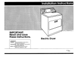
DRYER Before you start... Mark an X across the letter or number as you complete each step. lnsfallation is adequate and I” conformance with the National Electrical Code ANSI/NFPA 70.latest edition. and all local codes and ordinances. R~~eplacle (IO-30Rl Typical 30-ampere receptacle for use where local codes permit J-Wire reCepKX3e use of flexible power supply Figure cord [pigtail). 2. THE DRYER MUST BE CONNECTED WITH 10.GAUGE COPPER WIRE ONLY You need these tcols to install your Whirlpool electric drver. Get them toaether in one place lo keep track of thgm B Check the spot where you’re going to install the dryer... proper installation is Your responsibility. n Make sure You hove c. everything necessary for proper Installation. You’ll need: l To meet code requlremenls: some codes keep from or limit installation 01 clothes dryers in garages. closets, mobile homes atid sleeping quarters. [Check with your local buildino inspector.] Important: observe all governing codes and ordlnonces. . To check utllltles: proper connection lo electric supply should be available. l To check exhaust requirements: a four inch metal exhaust duct is required. LOCATION Size: Must be large enough to fully open dryer door. For recessed or closet installation spacing see Panel B. -= -I t Support: The floor must be able to supporl the appliance weight of 150 pounds. Level Floor: Maximum floor slope under dryer- 1 inch. Protectlon from the weather: Proper operation of dryer cycles requires temperatures above 45°F. or the dryer may not shut off when automatic cvcles are used. WARNING: Potential Fire Hazard l It is the personal responsibility of the customer to ensure that gasoline, paint, thinners and other flammable materials are not used or stored near the dryer. Fumes from these materloIs could result in fire or explosion, l Never install the dryer up against draperies or curtains and be sure to keep any and all items from falling or collectina behind the drver. l Replace%11 access ors&ce panels before operating dryer. Electrical requkments 1. A three-wire or four-wire, single phase, l20/24&volt. 60.Hz. AC only, electrical supply (or three-wire or four-wire 120/208-volt if specified on nameplate) is required dn a separate 30.ampere circuit. fused on both sides of the line. [Time-delay fuse or circuit breoker is recommended] Do Not have o fuse in the neutral or grounding circuit. The dryer wiring panel is located on the back panel. It ISthe personal responsibility of the customer to contact 0 qualified installer to assure that the electrical PANEL A 3. Local codes may permit the use of o U.L.-listed. 120/24&volt minimum, J&ere. dryer power supply cord kit (pigtail). This cord contains three. No.-10 copper wires and matches a three-wire receptacle of NEMA TYpe lO-3OR shown in Figure I. Connectors on the dryer end must be ring terminals or spade terminals with up turned ends. A 3/4’. U.L.-listed strain relief must be provided at the point the power supply cord enters the appliance. WARNING: Electrical Shock Hazard l Improper connection of the equipment-grounding conductor con result in electrical shock. l Use a new. 3& power supply cord kii. Possible electrical shock could occur if old power supply cord is used. l Do Not plug the power supply cord [pigtall] into 0 live wall receptacle beiore connecting the pigtoil fo the terminal block. Read “Electrical Connection:’ Panel A. for detailed instructions. 4:The appliance may be connected directly lo the fused disconnect or circuit breaker box through flexible armored or non-mefollic sheathed copper cable. Allow Iwo or three feet of slack in the line between the wall and the appliance so that it can be moved if servicing is ever necessary A K/4:U.L.-listed strain relief must be provided at each end of the power supply cord (at the appliance and at the jhnction box]. Wire sizes fCOPPER WIRE ONLY) and con&dions must conform with the rating of the appliance (30 amperes]. Do Not use on extension cord. Important: observe all govemlng codes and ordinances. 5. For mobile home or other four-wire Installations. the appliance wiring must be revised. The appliance cabinet must not be connected to the neutral terminal, but must be connected to the grounding wire [green] of the power supply cord. When four-wire receptacle of NEMA Type 14.30R is used (see Figure 2). a matching 120/24Uvolt minimum. 3Uampere. U.L.-listed dryer power supply cord kii (pigtail) must be used. This cord contoins four, No.-10 copper conductors with ring terminals or spade terminals with upturned ends on dryer end terminating In a NEMA Type 14-30P plug on supply end. The fourth (grounding) conductor must be identified by a green or green/yellow cover andthe neutral conductor bv a white cover. Cord should t;e TYpe SRD or SRDT. with a 3/4’. U.L -listed strain relief and be at least four feet long. The power supply le~~$% cord and strain relief are not provided with the dryer. conductors and connected to Ihe equipment-grounding terminal or lead on the appliance. Electrical ground Is required on thls appliance. This appliance is manufactured wlth Ihe neutral terminal connected to the cabinet. ELECTRICAL CONNECTIONS Make sure power supply ls turned off. A If local codes permit w connection of the cabinetgrounding conductor to the nevtml wire of the power supply cord: Exlemal gmundlng sonnector 1. cover bY removing Me screw shown in Figure 3. Figure 3 2. Anach a %/d:U.L.listed strain relief (U.L. marked on It] to the dryer through the power 44 ’ stmkl supply cord hole. (o”Ude dryer) See Figure 4. FilQure 4 Tighten strain relief firmly to cabinet. Place the power supply cord or direct wire through the strain relief. Tighten screws on strain relief. Ertwnal - grounding Fkw~ 5 wlra PO am=W WPP~Y cud Omunded omma,ng neutral 3. Connect the neutral wire on the power supply cord to the center silver-colored terminal of the terminal block and connect the other wires to the outer ferminals. See Figure 5. 4. Replace the terminal block cover bY firsi Installing the tab of the cover into the slot of the dryer rear panel [See Figure 3). Secure the cover with the mounting screw. 5. Direct wiring connection a. Strip outer covering buck 3 inches from the end exposing the 3 wires b. Strip the insulation back 1 inch from the end of each wire. Form the bare wire into a “U” shaped hook Figure 6 c. Loosen. do not remove, the center. silver-colored screw of the terminal block. d. Slide the end of the neutral (white or center] wire under the screw head with the open side of the hoolc on the right Squeeze the wire together to fan a loop. 8. nghten Me screw firmly. f. Connect the remaining 2 wires to the outer screws the same way fllghten screws firmly. 6. Tighten strain relief clamp on power suwlv cord See Fioure 4. 7. Re&& terminal block cover. GROUNDING INSTRUCTIONS This appliance must be connected to a arounded metal, permanent wlrlna sy;tem: or an equipkntgroundlng” conductor must be run with the circuit Direct wlrlng~cbnnection If local codes DO NOT permit cabinet grounding to the I neutral wire of lhe power supply cord: 2. Attach a %/d:U.L.-listed strain relref (U.L.marked on it) to the dryer through the power supply cord hole See Figure 4. Tighten strain relief firmly to cabinet. Place the power supply cord or direct wire through the strain relief. 3. Remove the grounding wire [green) from the external grounding connector and fasten under center silver-colored terminal block screw See Figure 7. WARNING: Polentlal Fire Hazard Exhaust Systems longer than specified will: . Accumulate lint. l Shorten the life of the dryer. l Reduce the performance in ways such as causing longer drying times and increasing the use of the energy For Exhaust Systems nof covered by the exhaust lengih chart. see WhIrlpool Service Manual, Exhausting WhIrlpool Dryers. Part No. 603197 available from your Whirlpool parts distribuioc. The back pressure in any exhaust sysiern used must not exceed .3 inches of water column measured with an inclined manometer at the point that the exhaust system connects to the dryer. For Moblle Home installation, the dryer must have an outside exhaust. If you exhaust the dryer through the the area under your mobile home is enclosed. the exhaust system must terminate outside the enclosed area Extension beyond the enclosure will orevent lint and moisture build-up under the mobile home. There are Exhaust Kits available that allow you lo direct flltered exhaust air inside to conserve energy during the winter months. Whirlpcel has a HeatHumidity Saver Port ko. 279427 which can be used with Whirlpool dryers providing their use does not violate local codes. If you use one of these kits, be aware that excessive moisture in the home can cause many problems and that you may see an increase in the time required to dry a I&. Also, you musl regularly clean the filter to avoid excessive lint build-up which can affect the dryer’s performance. Note: Do not use this kit on a dryer installed in a bedroom, bathroom or closet. B 4 wire ungrounded neulml 6. Replace the terminal block cover by first installing the tab of the cover into the slot ot ttie dryer rear panel [See Fiaure 31. Secure the cover with the m&tin& screw. 7. Tighten drain relief clamp on power supply cord. See Figure 4. Exhaust requirements 130ampere,, poweiwpply cord Ungrounded neulml 4. Connect the neutral wire of the power supply cord to the center silver-colored terminal of the terminal block and connect the other wires to the outer terminals. See Figure 7. For connecting plain-end field wires see Figure 6. 5. Connect a separate copper grounding wire [No. 10 minimum) to 6 grounded cold water pipe’ by means of a clama and then to the frame of the appiiance at the external grounding connector. Use Part No. 685463 grounding wire and clamp assembly. Do not ground lo o gas supply pipe or hot waler pipe. Do not connect the power supply cord to electric power supply we 8 6. Replace terminal block cover 7. Trghten strain relief clamp If connecting to a four-wire electrical system (mobile n homel: 1. Remove theierminal block cover by removing the screw shown in Ftaure 3. 2. AttOch a %:‘U.L.-listed strain relief IUL. marked on ii1 to the diver ihrough the pow& supply dord hole. See Figure 4. Tighten strain relief firmly to cabinet. Place the power supply cord or direct wire through the strain relief. 3. Remove grounding wire [green) Irom the external grounding connector and fasten under center sliver-colored terminal block screw. 4. Connect the grounding wire (green] of the power supply cora to the external grounding connector, 5. Connect the neutral wire [white) of the Power supply cord to the center sliver-colored terminal of the terminal block and connect the other wires to the outer terminals. See Figure 9. For connecting plaln-end field wire. see Figure 6. C WARNING: Potenflal Fire Hazard Metal flexible duct may be used Do Not use non-metallic flexible duct since it is a potential fire hazard. Far Safety: l Do not exhaust dryer info a chimney. furnace cold air duct, attic or crawl space. OTany other duct used for venting. Accumulated lint could become a fire hazard or moisture could cause damage. l Clean the exhaust system periodically. at least every 2 years l Never install flexible duct concealed in walls, ceiling or under flooring. Four Inch Metal Exhaust Duct is required Use Duel Tape to seal all joints. To exhaust through botlom or sides use Kit 693754 available from your Whirlpool dealer. WARNING: Polentlal Fire Hazard To exhaust out the sides or bottom of dryer, vou MUST use Kit 693754 Failure o dd so &an result in a potential fire hazard. Exhaustlna the drver outslde is recommecded If ;ou cannot exhaust the dryer to the outside, use Exhaust Deflector Kit LCK4000 available from your ’ Recessed Area Instructions INSTRUCTIONS FOR RECESSEDOR CLOSEI INSTALLATIONS The following installutlon spacings and door air oceninos fcf the drver are possible when i&tolled and exhausted as noted. (Spacing as indicated is in inches and is minimum allowable. Fol ease of installalion and service. additional spacing should be considered.1 TO PREVENT LARGE AMOUNTS OF LINT AND MOBlURE FROM ACCUMULATING AND TO MAINTAIN IS -_ DRYER MUSI up. down. left, right or Straight out the back of the dryer. Detailed space requirements can be found in Recessed/Closet Installations, Panel B and on the label on the back panel of dryer. Metal Flexible Duct must be fully extended and supporled when the dryer is in its final positi DO NOT KINK OR CRUSH THE D An Exhaust Hood should cap the exhaust duct to prevent exhausted air from returning into dryer. The outlet of the hood must be at least 12 inches from the ground or anything else that may be in the path of the exhaust. A 2K Inch outlet Exhaust Hood should be used with short systems only. (This outlet creates greater back pressure than other hood types.] Exhaust Hoods with magnetic latches should not be used. The Maxlmum Length of the exhaust system depends upon the type of duct used. number of elbows and type of exhaust hood. The maximum length for both rigid and flexible duct is shown Unobstnrcted air cpenlngs are required for laundry equipment when door is installed. Closet installation must be exhausted. Onlv recessed installations with no cabined of shelf above the dryer can be non-exhausted. Non-exhausted recessed Installations require an exhaust deflector. Front view AllI -II- +I 0” It ~II Slde view Compunion appliance spacings should be considered Detailed space requirements are located on the label on the back panel of dryer. Front vlew t -. Now start... ’ 2 Open dryer and remove the ports packages. (If your dryer has a drying rack it should be removed also.) Remove all parts from the plostrc packages. Line these up next to your tools so each part is there when you need it Check to see that you have these parts: 3 Remove the tape n that holds the drum to the cabinet [Some dryer drums ore not loped for shipping.J Move the drum by hand to make certain all tape has been removed Wipe the interior of the drum thoroughly with a damp cloth before using the dryer. Remove tape from lint screen. 11 Check to see that all of the ports you removed from the installation parts packages in step 2 are now InStaffed in the dryer. If you still have an extra part. go back through the steps to see what you skipped n dtxard corners from the carton and place them on the floor in back of the dryer. 5 Firmly grasp the n body of the dryer and gently lay it on its back on the cardboard corners 8m Move the dryer to its permanent location. To make sure the dryer is level. take CIcarpenter’s level and pkX0 it on the top of the dryer, first side to side. then front to back. If the dryer is not level, screw the legs of the dryer up or down to adjust. To exhaust the dryer. 13 ’ Check to make sure you have oil the tools you started with in step A. around exhaust hood 6 Start to screw n the legs into the holes by hand A little lisuid detergent to lubricate the screw WIII help. Use an adjustable wrench to finish turning the legs until you have 1” of the screw threads remaining. 7 H Now stand the dryer up PANEL C 6n)oymmlthomywr newdryer,mad ywr Whldpool Opemtlng Instructbns. (And be sure to (dd thea0 ItUtOllatlOn inskuctlonsandputlhemln~ 1110roture BOC-Pak. lhevll make re4utalllng your WhIrlpod dryor In anottw hOme aa easy as your tint Installallon.) tabs lock in when movie your dyer... : “. .shutosfeiectflcsuppiytodryer. It dryer does not operate Pw=b ifdryerwiiinotoperate.checkthe foiiowlng to be sure that: A. Eie&ic supply is ccnnected. B. Fuse is intact and tight. c.Doorisclosed. D. Controis are set in a running or “on”pdtion. E.Startbuttonhasbeenpushed firmly or the power coniroi level moved upward to start. Disunneg electrical c&and., tapeseagelybdryer. ‘zj.***ll Tapethi3dfumtothefrcntpanei. l Tapedryerdocxandiintxzeen.. l Screw le&iin~ legs ail fhe way in. Before having your eiectlic dryer installed in ycur new home, check wtlh a licensed eie&ician to conform that the supply voitage matches the voikge specified on ihe nameplate. l During normal business hours. the Whiripooi COOL-LINE” Service till answer any questiw about operating or maintaining vourdrvernotcovemdinvour tlpemiinQirrstructlons.Th;, Whirlocal COOL-LiNE@Service number is (BCO]253-1301. Dial just as you nc+maiiy diii kx?g distance -the cull is free. RJftrb.3389580Rev. B 8199owhMpoolC0tporaiion b+XWd -. e by whktpcxd Corporation, 01 OxmFwwN Benton Harbor, Michigan 4%X2! Pdnted in U.S.A.