1
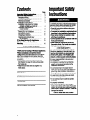
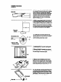
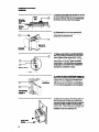
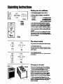
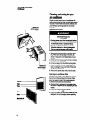
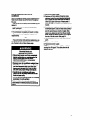
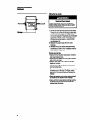
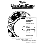
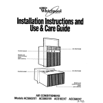
T&+1
3
01
Installation
hiLtionsand
UseMareGuide
Model and serkl
number plate
-(behlndfrontpanel)
r
Control panel
I
Control panel
Model and
serial number
AIRCONDITIONERS
ModelsACS602 ACS802 ACSlOP ACC602
a-%
Contents
Important Safety Instructions. . . . , . . . .
Electrical Requlnments
.........,....
Receptacle wiring . . . . . . . . . . . . . . . , . . . .
Electrical requirements . . . . . . . . . . . , . . . .
Elect&al connection . . . . . . . . . . . . . . . . .
Instsllatlon Instructions.
............,
Installation instructions for models
ACS602, ACS602 and ACS102 . . . . . .
Installation instructions for
model ACC602 . . . . . . . . . . . . . . . . . . . .
Operating Instructions
...............
Starting your air conditioner . . . . . . . . . . .
The exhaust control . . . . . . . . . . . . . . . . . .
Changing air direction . . . . . . . . . . . . . . . . .
Cleaning and caring for your
air conditioner . . . . . . . . . . . . . . . . . . . . .
H You Need Service Or Assistance . . . .
WhIrlpool Room Alr Conditioner
Warranty . . . . . . . . . . . . . . . . . . . . . . . . . . . .
mportant
Safety
P&N
nstrudions
-2
3
:
3
4
4
6
11
11
11
11
12
15
16
01990 Whirlpool Corporation
Thank you for buylng a Whirlpool appliance.
Piease complete and mall the Owner
Aeglstratlon Card provided wlth this product. Then complete the form below. Have this
information ready if you need service or call with
a question.
l Copy model and serial numbers from plate
(see diagram on page 12) and purchase date
from sales slip.
l Keep this book and sales slip together in a
handy place.
M-1
Number
Sertrl Number
Purchaee Date
Ssrvka Com~nny Phone Number
r0 reduce the rtsk of firs, Mctrksl shock of
mraonai injury wbeh using your air condi:ioner, follow these basic precautions:
1Read ail instructions i&ore using your
air conditioner.
1Complete the installation requirements as
described in the instaliatlon Instructions.
) Never allow chlidren to operate or piay
with the air conditioner.
) Do Not operate the alr conditioner with tbs
front panel removed.
1Never clean air conditioner parts with
flammable fluids. The fumes can create a
fire hazard or explosion.
l FOR YOUR SAFETY.
DO NOT STORE OR USE GASOLINE OR
DTHER FLAMMABLE VAPORS AND LIGUIDS IN THE VICINITY OF THIS OR ANY
DTHER APPLIANCE. THE FUMES CAN
CREATE A FIRE HAZARD OR EXPLOSION.
t is your responsibility to be sure your
air conditioner:
) Is installed in a window that will hold the
weight, and is secured according to the
Installation Instructions.
BIs connected only to the proper kind of
outlet, with the correct electrical supply and
grounding. (See Installation Instructions.)
) Is the right size for the area you want to cool.
DIs used only to do what window air conditioners are designed to do.
) Is not used by anyone unable to operate
it properly.
BIs properly maintained.
) Also, remove the Energy Label and Buy
Guide. Use a damp cloth to take off any glue
residue. Do not use sharp instruments, flammable fluids or abrasive cleaners. These can
damage the material.
- SAVE THESE INSTRUCTIONS -
ElectricalRequirements
Electrical requirements are different for the two
models pictured on the cover, depending on the
ampere rating of your unit. The number of
amperes is printed on the serial plate, which is
attached to the front of the unit behind the front
panel. (See diagram on page 12.)
Observe all local governing codes and
ordinances.
Do not, under any circumstances, remove
the power supply cord grounding prong.
Electricalrequirements
l
Receptadewiring
Receptacle wiring should be a minimum of 14
gauge. Use copper wire only. It is the responsibility
of the consumer to provide proper and adequate
receptacle wiring installed by a qualified electrician. Observe National Electrical Code and all
local governing codes and ordinances.
l
l
Electrical Shock Hazard
Check with a qualified electrician if you
are in doubt as to whether the appliance Is
properly grounded. Do not modify the
power supply cord plug - if it will not fft
the outlet, have a proper outlet installed
by a qualified electrician. improper
connection of the equipment-grounding
conductor can result In a risk of
eiectrlcai shock.
Do not use an extension cord with this
appliance. Such use may resuit In a fire,
eiectrlcai shock or other personal Iniuw.
Do not have a fuse in the neutral or
grounding circuit. This could result In a
risk of eiectrlcai shock.
A 115volt, 60 Hz AC only, 15 ampere fused electrical supply is required (time delay fuse or time
delay circuit breaker required). It is recommended
that a separate circuit, serving only this appliance,
be provided for models with serial plate amperes
up through 7.5. A separate circuit is required
for models with serial plate amperes of 7.6
through 12.0.
Electricalconnection
Electrical ground is required on this appliance.
&Prong
Recommended grounding method
For your personal safety, this appliance must be
grounded. This air conditioner is equipped with a
power supply cord having a 3-prong grounding
plug. To minimize possible shock hazard, the cord
must be plugged into a mating 3-prong grounding
type wall receptacle, grounded in accordance with
the National Electrical Code, ANSVNFPA 70-l&
(or to the latest), and local codes and ordinances.
If a mating wall receptacle is not available, it is the
responsibility of the customer to have a properly
grounded 3-prong wall receptacle installed by a
qualified electrician.
3
Eloctrlcal Rsqulramsnts
Continusd
Electrically
grounded metal
coid water pipe
(removepelnt,etc.)
Ground assembly
(attach to grounded
metal cold water pipe)
7
f
1
Grounded eyelet
all
receptacle
~‘-
1
t--Gmundlng-
Temporary grounding msthod
If changing and property grounding the wall recap
tacle is impossible and where local codes permit
(consuft your electrical inspector), a temporary
adapter may bs plugged into the existing P-prong
wall receptacle to mate with the 3-prong power
supply cord. This, however, is not recommended.
If this is done, however, you must connect the
grounded eyelet on the adapter to the wall mcep
tacfe cover plate screw and from this same screw,
you must connect a separate copper ground wire
(Xl4 minimum) to a grounded cold water pipe.
‘Do not ground to a gas supply pipe. Do not
connect to electrfcal supply until appliance is
grounded. Do not, under any circumstances,
remove the power supply cord grounding prong.
‘Cold water pipe must have metal continuity to
electrical ground and not be interrupted by pIastic, rubber or other electrically insulating corlneCtors (including water meter or pump) wfthout
adding a jumper wire at these connections.
InstallationInstructions
For models ACS602, ACS802 and ACSlOP, follow
installation instructions below. For model ACC802,
follow installation instructions on page 8.
InstallationInstructionsfor
modelsACS602,ACM02
andACSIM
To help avoid any installation problems and to help
assure trouble-free perfomtance of your new air
conditioner, read these installation instructions, as
well as the operating instructions and electrical
requirements before installing your unit.
Personal InJury Hazard
Because thls air conditioner wslghs about
90 to 105 pounds, it is recommended that
you have somsons hsip you Install your
nsw unit and that you both uss propsr lifting techniques.
l Inspect the condition
of ths wlndow whefa
ths air condftionsr will be Installed. Bs
sure it wlii support the weight of ths unit.
l mh
appliance must be Instalisd accord
ing to ail applicable codes and
ordinances.
0 Handle ths air wndttlonsr wlth care.
Watch out for the sharp metal ffns on ths
front and rear colis.
l Be sum air conditioner
doss not fall oui of
window during or aftsr lnstaliatlon.
mDo not uss ths collected watsr for drinking
purposes. It is not sanitary.
Faiiurs to follow ths abovs prsoautions
could msuit In psrsonal Injury.
l
1. Unpack mounting parts before installing
your air conditioner. Make sure you have all the
necessary parts. A normal installation can be
made with a screwdriver, saw, small level, pocket
knife, tape measure, drill and Ye: VW”and %s”
drill bits.
Description of parts
1 Shelf (1)
2 Support bracket (1)
3 Sill bracket (1)
4 VW”bolt (2)
4A %s” nut (2)
48 W’ flat washer (2)
4C %6’ lockwasher (2)
5 Translucent panel (1)
6 Screw-10x1”(2)
6A screw - 10 x 13/4” (2)
7 Screw - 8 x Vi” (5)
8 Side seal strip (1)
9 Lower track seal (1)
10 Locking bracket (1)
11 Foam seal strip (1)
12 Panel frame (1)
13 Thread cutting screw #B/J2 x W’ (4)
If using Item 13 for fastening Item 10 or 12 to metal
or plastic, use VW”dia. or #28 drill.
2. Pick the correct window. First, decide what
room(s) you want to cool. Then choose a window
that will allow the air-conditioned air to flow freely
and directly into the room(s) you want cooled.
Remember, it’s difficult to move air around corners.
If the inner sliding window slides to the left, the unit
will be installed on the right. Remove window
screen if there is one. Choose a sliding window
that’s also near an electrical outlet. (Refer to
“Electrical Requirements” on page 3 for type of
receptacle and wiring needed.) Do not use an
extension cofd.
The sliding window in which you place your air
conditioner should have an opening of at least
15%” wide and 21%” to 40%” high (see diagram).
For installations up to 62%” high, a special kit (Part
No. 977449) is available. For windows as low as
20%~‘:you must install without filler frame and
remove top angle on unit, reinstalling 3 screws into
top of cabinet.
This model may also bs installed in steel hinged
casement windows. The steel hinged casement
window must have an opening at least 15%” wide
and no more than 18%” wide.
3. Place shelf in window wlth tabs down
against the track surface.
5
Instdlsth
Contlnwd
InstmcUoms
4. Attach support bracket (Item 2) loosely to
the underside of shelf with either short or long leg
down and with end of bracket either toward or
away from window, depending upon con&uction
and depth of wall and window sill (see diagram).
Attach sill bracket (Item 3). Each bracket is
attached using one %s” bolt, nut and washers
(Items 4,4A, 48 and 4C).
Room side
t
-It=-“‘”
Uw screws 5 or 5A
5. With the assembled shelf and brackets still
in the window opening, adjust brackets until she8
is firmly seated and sloping down to outsiie. If you
use a level, be sure you have ?I2bubble of slope.
Wtiout a level, place the translucent panel (Item
5) on shelf. The top of long side of the panel will be
%s” back from the window line (see diagram).
5. If slope back is correct, tighten all nuts
securely. Install lower track seal (Item 9) shown in
diagram. This track seal has two holes which line
up with matching screw holes in shelf.
Prodrill ‘Hu”holes
if truks are metal
7. install shelf 2%” from side of window opening, securing it in place with screws 6 or 8A.
8. Measure height of opening (see diagram).
Subtract 20%~” from measured height. This will be
the actual height of translucent panel.
9. Measure out the distance determined in
Step 8 and mark it along the 20%” side of translucent panel. Clamp panel between a board and an
appropriate supporting surface close to the mark
and cut with fine tooth saw. Remove burrs.
10. Lift vertically removing panel frame from
unit. Slide translucent panel into groove in frame,
keeping honeycomb side to the face side of frame
(see diagram). Slide frame back into place on unit.
Panel should enter the top angle groove.
8
11. Peel backing from seal strip (Item 8) and
press it onto side filler frame guides on each side
of unit.
seal strip
Slldlng
sash
IL
. sesl
strip
12. Place unit in window by testing unit on
shelf. Push unit toward window so side angles are
sealing against the side jamb stop (see diagram).
Slide the opened window sash firmly to make certain the frame and unit sealing strips are sealing.
sod
strip
13. Using %I” drill, install locking screws
(Item 7). Use two screws in top jamb and in the
side bottom flanges. If you need additional holding
strength, add two more screws at upper sides of
filler frame (marked “A’). Also, two screws can be
added at unit sides (marked “6”). However, if you
add screws at “6,” you must use a %I$ drill bit to
predrill through the plastic sides of air conditioner.
Slldlng sash
14. Lock the sliding sash at bottom using lock
bracket (Item 10) and screw (Item 7) as shown in
diagram at left. Use a W’ drill bit to drill through
track before inserting screw.
Thck
(room side)
15. Cut seal strip (Item 11)to length. Install it
between space of opened sash and glass of the
closed sash (see diagram).
7
Mdsngk
16ort66au6a
Addwood
ushown
Add l ngt8
towoodstop
16. For lnstallatlon In windows havlng no
side flanges or with wood stops.
The flanges (top and two sides) on the air conditioner must mate against companion flanges on
the window, not more than %s” (.2 cm) in thickness.
On the side with the opened sash, the leading
edge of the sash becomes the flange. On the top
and jamb side of most metal windows, the flange
is there.
In windows where there are no flanges or where
there are thick wood flanges or stops, use metal
angles or wood to provide a stop for the unit
flange. Diagrams at left show three suggested
methods.
17. For installation in steel casement
windows.
Follow Steps 2 and 3 on page 5. NOTE In
Step 3, the shelf tabs must butt to the front of fhe
bottom angle on the casement (see diagram
at left).
When Step 3 Is flnlshed, follow Steps 4
through 10 on page 6, and Steps 11and 12 on
page 7. Then proceed with the final two paragraphs in this Step 17, which immediately follow.
Open wlndow at least 18(p to allow room for
unit cabinet. If necessary, remove window crank
handle so the window will open wide enough. Tii
opened window to the wall or frame to prevent the
window from swinging.
Drill Vu” holes in the window jamb top to
line up with holes in filler frame (see diagram at
left). Use two thread cutting screws (Item 13) to
secure unit. If you need additional holding
strength, add screws at the bottom of the unit
side channels (see Step 13 diagram).
14%”
y
I
RI
Center unlt In
Room
l valkbk eponhq i
Installationinstructionsfor
modelACC602
To help avoid any installation problems and to help
assure trouble-free performance of your new air
conditioner, mad these installation instructions, as
well as the operating instructions and electdcal
requirements before installing your unit.
Inspect the condition of the window where
the air conditioner will be installed. Be sure it will
support the weight of the unit.
I
Personal InJury Hazard
Bewraalrcondltlonerdoesnotfalloutof
window during InsfallaUon. Pomona1 InJury
ordamagecoufdruult.
I
8
Fersonal InJury M
Becauss this alr condltloner weighs &out
78 to 75 pounds, it Is recomthat
you have somsone help you Install your
newunltandthatyoubothuse~llftlng techniques.
l This appliance must be Installad
according to all appllcabla codes and
ordinances.
l Handle the air condltloner
wlth care.
Watch out for the sharp metal flns on ths
front and rear tolls.
l Do not use the collected
water for
drlnklng purposes. lt Is not sanitary.
Fallum to follow ths above precautkns
could result In parsonal InJury.
l
1. Unpack mounting parts before installing
your air condiiioner. Be sure you have all the netessary parts (see top two diagrams at left). This air
conditioner will fit most steel casement windows. A
nom-ratinstallation can be made with a screwdriver, W socket driver, tape measure and drill.
Description of parts (top two diagrams at left)
1 #lO x 3/e”long s.m. screw
2 #l O-32 x 3/e long math. screw
3 Bottom mounting bracket
4 Knurled knob screw
5 Top mounting bracket
NOTE: Above parts (not shipped loose) installed
on unit by factory.
2. Pick the correct window. First, decide what
room(s) you want to cool. Then choose a window
that will allow the air-conditioned air to flow frwfy
and directly into the room(s) you want cooled.
Remember, its diiicult to move air around comers.
Choose a window that’s alao near an ektrical
outlet. (Refer to “Electrical Flequirlements” on
page 3 for type of mceptacle and wiring needed.)
Do not use an extension cord.
To be able to use the window mounting parts
shown in the diagram to the left of Step 1 aboW,
the window should have a minimum width of 14%”
and a maximum width of 16” (see “A” in bottom
diagram). Ths window shoufd have a minimum
height of 10%” and a maximum height of 11W
(see 9” in bottom diagram).
3. Remove the glass from the frame opening
selected. Clear away any hardened putty.
4. Before slldlng unit through the casement
opening, remove the bottom window bra&t
(Item 3) on both sides of the unit. NOTE: Only the
topscmws(lteml)needtoberemoved.
9
Inst8lktlon
Continued
In-s
5. Check the knurled knob screws to see that
the top mounting brackets (Item 5) are Mracted to
the center of the unit. They must not interfere witft
the window frame when the unit is installed.
6. Lift the unit into the window opening and
slide it back until the mounting frame comes into
contact with the window frame.
7. Replace the bottom mounting brackets
(Item 3) by hooking the bracket over the window
frame. Replace the top screws (Item 1) in the
mounting bracket, leaving them loose enough so
them is about %s”of play Tighten the bottom
screws (Item 2). This will pull the unit mounting
flange tightly to the window frame, sealing and
locking the air conditioner in place.
Y4”
Max. -I
I_
Back of air
condltlonor
8. Loosen the two knurled knob screws and
slide the top mounting bracket (Item 5) toward the
outside of the unit, engaging the window frame.
Tighten the knurled knob screw in this position.
This will lock the unit in place so it cannot tftt into
the room. The Installation Is now complete.
9. Optional mounting instructions. If the window thickness will not allow you to use the four
mounting brackets provided with the unit, remove
brackets and fasten flanges of unit with sheet
metal screws. These screws are not included with
your air conditioner. The window opening for your
installation must not be wider than 151
shestlnsw
SWOWS10
Operating.
Instructions
Startingyourair conditioner
l.Setexhaustcont~0I(iiyourunitisso
equipped) to CLOSED for maxfmum cooling.
2.ChooseeitherLOCOOLorHICOOLfan
speed aetling.
LOCOOL . . . . . . . . . . . . . . fors&epklgcomfort
HICOOL . . . . . . . . . . . . . . formaxfmumcooflng
FANONLY . . . . . . . . . . . . forcim&tfngroomeir
whennocoolinglsdealled
3. lbrn the thermostat conb’olto06
(mid-setting). You can a@st the air amWooer
cooling performance by-%l*
L
control to a higher number for IM&UTI cooling.
Lower the number setting for less arolfng. Mu wfll
need to experiment to find the setting which s&3
you best.
NOTE: If you turn your air conditioner off or if the
compressor shuts off, wait at least tfuee minutes
before turning it back on or you may blow a fuse or
trip a circuit breaker.
CLDWD
WEW
“Ml,
OFF
LO Coo(
Fan
only
CLDSED
WIT DFF
Theexhaustcontrol
The exhaust control setting draws stale or smoky
air from the room.
1. To exhaust room alr
Set exhaust control to OPEN. Adjust fan control
to speed desired. If no cooling is desired, use FAN
ONLY setting.
2. To circulate room alr
Set exhaust control to CLOSED. Adjust fan control
to FAN ONLY
Changingair direction
The louvers in the grille area at the top of the air
conditioner control the direction of the coofed air
If your untt looks Ike Flgure A, move
the lever at the top of the grille to the right, feft or
straight ahead. Simply move the lever in the
direction you want the air to go. me rear verkal
louvers in the grille can be adjusted left, rfght or
straight ahead. The front set is fixed and directed
upward.
If your unit looks Ike Figure B, turn the
circular air discharge grilles on top of the unit. Both
grillescanbeadjustedtotherfghtorfeft+oradjusted indivfdually.
11
Cleaningandcaringfor your
air conditioner
Model and
wrlal number
Proper use and care of your air condiiner will
help ensure lonaer life of the unit and lower operating’costs. Follow these instructions carefully.CalI
your Whirlpool servicing dealer for an annual
checkup.
Cleaning front panel
l
l
ElectrIcal Shock and
Flra Hazard
Unplug power cord from receptacle before
cleaning unlt. Failure to do so could mlt
In electrical shock or personal Injury.
Do not use flammable flulds, solvents,
abrasive cleaners, or strong detergents.
Fire or product damage could result.
1. Remove the front panel from unit when clean-
Mod.1 and
urlal numkr
plate
ing. Press down at top edge of the front, as
shown in diagrams at left (depending on your
model).
2. When the front moves away from top of cabinet,
pull top of front toward you.
3. Lift up and away from the bottom spring clips.
4. Clean front panel with warm water and mild
soap or detergent. Use a soft cloth. Rinse and
dry. Replace front panel.
5. Wipe control panel clean with a soft dry cloth.
Cleaning air conditioner filter
The filter is cleanable. A clean filter helps remove
dust, lint and other particles from the air. Check
every two weeks to see if filter needs cleaning.
1. Remove front panel as shown above.
2. Remove filter by releasing it from plastic clips
as shown in diagrams at left (depending on your
model).
3. Clean filter, using a vacuum cleaner.
-OR4. If very dirty, wash filter with warm water and mikf
detergent. Air dry thoroughly before replacing.
Annual maintenance for your air
condttloner
Your air conditioner needs annual maintenance to
help ensure steady, top performance throughout
the year.
Call the service company recommended by your
dealer to:
l Inspect and clean the coils and condensate
water passages.
l Check fan and oil the fan motor.
l The compressor is sealed and needs no oiling.
Expense of annual inspection is customer’s
responsibility.
-ORlf you are familiar with electrical appliances, you
can do the cleaning and maintenance yourself. If
you choose to do so, follow these steps:
1. Disconnect power supply.
2. Remove unit from cabinet. Wrap the motor,
electrical control box and electrical terminals
boxinplasticfilmandmakesumnowateror
other liquid gets inside any of these parts. lt
could damage the insulation and cause serious
trouble.
3. Carefully clean and hose out the base, coils and
condensate pans. Clean at least once a year or
more often if the condenser coils and pans collect dirt, sand, leaves, insects or algae. Also,
cleanifyoudetectanodorfmmtheaircondftioner. While the cabinet is open, this is a goal
time to oil the fan motor. See page 14.
4. Remove plastic film from motor and elecfri&
parts.
5. Replace unit in cabinet.
6. Reconnect power supply.
NOTE: II is a good idea to wait 24 hours before
starting the unit again. This albws time for all
amastodryout.
EbctrlcalShockand
Personal Injury Hazard
l Dbconnwtpowercordfromreceptwb
before performlng any maintenance. Be
sure no llquld gets Into the motor,
ebctrkal control box or compwsor
ebctrkal termlnab.
l Ebcause your alr condltloner
weighs fmm
70to105pounds,ltbrecommendEdtha
youhavetxBmaonahelpyouwhenyou
remove and reinstall your unlt and that
yoUbothll&9propMllftlngbChfIlq~.
l Handb the alr condmmrwtthcare.
Watchoutforthesharpmetalflnsonthe
front and reer colb.
l Donotu6ethecolbctedwaferfordrlnklng
purposea. ft Is not sanltafy.
Fallure to follow the above precmutlona
couldmsultInebcWcal
-orWw
13
Olllng the fan motor
Electrlcal Shock Hazard
Disconnect power cord from receptacle
before oiling motor. Fallure to do so could
result In personal InJury.
1. Oil the fan motor per instructions on the motor.
To add oil, pull out the oil hole plug at each end
of the motor (see diagram). An easy-to-use
one-ounce capsule of especially recommended
oil (Part No. 10943) can be ordered from your
Whirlpool servicing dealer, or use SAE X20
non-detergent oil.
2. Replace the plug to keep dirt from motor
bearings.
3. Reinstall the unit in cabinet after performing
maintenance. Refer to the “Installation instructions” section for your unit.
Energy saving tips
l Improve home insulation (seal doors, windows,
and close fireplace flue).
l Close blinds or drapes on sunny side of house;
add window awnings.
l Keep air filter clean. Don’t block air flow with
drapes or furniture.
l Ventilate attic (high temperature levels add to
normal cooling load).
l Try not to use heat producing appliances during
the honest part of the day. Turn lights, radios,
televisions, and other appliances off when not
needed.
l Keep heat registers and cool air returns closed
or blocked off so cooled air won’t escape.
l Use a vent fan in areas where cooking, laundry,
or bathing is done to pull out extra heat and
moisture near its source.
14
If YouNeedServiceOrAssistance
Wesuggestyoufollow
thesesteps:
1. gefore calling for assistance...
Performance problems often result from little things you
can Lnd and fix your&
without tools of any kind.
Air oendWonor
won? run:
Is unit plugged into a live circuit with proper voltage?
l Is swttch turned on?
l Is thermostat
set correctly?
l Has a fuse blown or a circuit breaker tripped?
l Has the local power failed?
l
3. if you need service?..
Whirtpoolhasanationwide
- workof-Whi&
vkf
01
ssnriceannpaniw3.whirlpool
(KRVICE servicetechniciansar9batned
l9
tofllHilltheprodlGt~and
provide after-warranty servtce, anywhere in the united
States. To locate the authorized Whfdpool m
con+
pany in your area, call our COOL-LINE0 m
as&tante telephone number (see Step 2) or bok In your
telephone directory Yellow Pages under:
Unit blows fuses or trips circuit breaker:
l
l
l
l
l
l
l
XYf2;EMy;;
COMPANIES
CO
.%9-m
extensfon cwd to run your air condltloner.)
4. if you have a problem:..
Are you waiting three minutes after turning cooling
circuft off before trying to restart unit?
Call our COOL-LINE service assistance telephone
number (see Step 2) and talk with one of our cons~fMM%
or if you prefer, write to:
Mr. Donald Skinner
Director of Consumer Relations
Whirlpool Corporation
2ow M-63
Senton Harbor, MI 49022
Please include a daytime phone number in your
correspondence.
Unittumsonandoff,ordoesnotcooiroom:
l
SERVICE
Am time-delay fuses being used?
Is an extension cord being used? (Do not use an
Is fitter clean?
Am coils clean (both evaporator [inside] and condenser
b-w)?
Is there excessive moisture or heat (open vessel cooking, showers, etc.)?
Try setting fan to higher speed.
Try setting thermostat to a cooler setting.
operating
sounds:
l When your room air conditioner
is operatfng
nomuiiy, you will hear sounds such as:
l Droplets of water hitting the condenser, causing a
‘pinging” or “clicking” sound. Water droplets help to
coolthe condenser.
l Air movement from the fan, especially
on high fan
speed -%I.
l Clicks from the thermostat cycle.
l Sounds also may be caused by house construction
such as vibration of the unit due to wall construction or
unsteady window mounting area.
2. if you need assistance’...
Call WhIrlpool COOL-LINE@ wrvlco assistance
w
numkr. Dfai free from a-r,
. IntheU.&
l-am-253-1301
andtatkwkhoneofourtrainedconsuttants.Theconsultantcaninstructyouinhowtoobtafnsattsfactoryoperattonfromyourapptianceor,ifsewiceisneceeaary,
tecomrnencl a qualified senrice company in your area.
6. if you need FSP@replacement
parts?..
FSP is a registered trademark of Whirlpool Corporation
for qualii parts. Look for this symbol of quatii w
you need a replacement part for your Whirtpool
appliance. FSP replacement parts will fit rtgM and ti
right, because they are made to the same exacting specifications used to build every new Whirlpoot appliance.
To locate FSP replacement parts in your area, refer to
Step 3 above or call the Whirtpool COOL-LINE m
assistance number in Step 2.
6. if you are not satisfied with how the pro&km
was soived~..
Contact the Major Appliance Consumer Action Panef
(MACAP). MACAP is a group of independent amsumer experts that voices consumer views at the highest levels of the major appliance industry.
l Contact MACAP only when the dealer, authorized
sewicer or Whirlpool have failed to resofve your problem.
Major Appliance Consumer Actton Panet
20 North Wacker Drive
Chicago, IL 6CNO6
l MACAP will in turn inform us of your actton.
‘When requesting assistance, please provtde: model
number, serial number, date of purchase, and a
oompietedeacripiionoftheprobtem.Thle~
isrwededinordertob&errespondtoyourrequeet.
l
15
Whirlpool”RoomAir Conditioner
Warranty
LENGTH OF WARRANTY
FULL OWE-YEAR WARRANTY
From Date of Purchase
1 WHIRLPOOL WILL PAY FOR
FSP@replacement parts and repair labor to correct defects
in materials or workrnanshib.
FULLFIVE-YEAR WARRANTY
From Date of Purchase
FSP replacement parts and repair labor to correct defects in
materials or workmanship in the sealed refrigeration system.
These parts are:
1. Compressor 4. Drier-Strainer
2. Evaporator
5. Connecting Tubing
3. Condenser
WHIRLPOOL WILL NOT PAY FOR
A sefvice calls to:
1. Correct the installation of the air conditioner.
2. Instruct you how to use the air conditioner.
3. Replace house fuses or correct house wiring.
4. Clean or replace air filter.
B. Pi up and delivery. This product is designed to be repaired in the home.
C. Damage to the air conditioner caused by accident, misuse, fire, flood, acts of God or use of
pmhcts not approved by Whirlpool.
’ D. The removal and reinstallation of the air conditioner if it is installed in an overhead or other
ineccessible location or not installed in accordance with published installation instructions.
Bewke under the full warranties must be provided by an authorized Whirfpoolsu service company.
WHIRLPOOL CORPORATION SHALL NOT BE LIABLE FOR INCIDENTAL OR CONSEQUENTIAL
DAMAGES. Some states do not allow the exclusion or limitation of incidental or consequential damages so
thii limitation or exclusion may not apply to you. This warranty gives you specific legal rights, and you may
alao have other rights which vary from state to state.
Gutside the United States, a different warranty may apply. For details, please contact your franchised
Whirlpod distributor or military exchange.
lf you need servfce, first see the ‘Service and Assistance” section of this book. After checking ‘Service
and As&tan&
additional help can be found by calling our COOL-LINE@service assistance telephone
number, 1-8OOk-13Ol,
from anywhere in the U.S.
Part No. 511664/4316224
91990 Whirlpool Corporation
WP JAN. 90