1
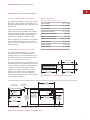
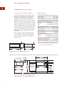
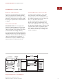
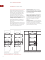
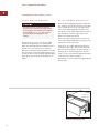
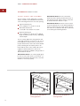
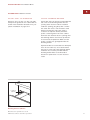
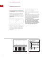
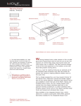
W A R M I N G D R AW E R
I NSTALLATION I NSTRUCTIONS
C O N TA C T
I N F O R M AT I O N
Wolf Customer
Service:
800-332-9513
Website:
wolfappliance.com
As you follow these instructions, you will
notice WARNING and CAUTION symbols.
This blocked information is important for the
safe and efficient installation of Wolf equipment. There are two types of potential
hazards that may occur during installation.
signals a situation where minor injury or
product damage may occur if you do not
follow instructions.
states a hazard that may cause serious
injury or death if precautions are not
followed.
Another footnote we would like to identify is
IMPORTANT NOTE: This highlights information that is especially relevant to a problemfree installation.
WOLF ® is a registered trademark of Wolf Appliance Company, LLC
W O L F WA R M I N G D R AW E R
I N S TA L L AT I O N R E Q U I R E M E N T S
IMPORTANT NOTE: This installation must be
completed by a qualified installer or Wolf
authorized service center technician.
Installer: Please read the entire Installation
Instructions prior to installation. Save these
instructions for the local inspector’s reference, then leave them with the homeowner.
Homeowner: Please read and keep these
instructions for future reference and be sure
to read the entire Use & Care Information
prior to use.
Any questions or problems about the
installation should be directed to your Wolf
dealer or Wolf Appliance Company, LLC at
800-332-9513. You can also visit our website
at wolfappliance.com.
IMPORTANT NOTE: This appliance must be
installed in accordance with National Electrical
Codes, as well as all state, municipal and local
codes. The correct voltage, frequency and
amperage must be supplied to the appliance
from a dedicated, grounded circuit which is
protected by a properly sized circuit breaker or
time delay fuse. The proper voltage, frequency,
and amperage ratings are listed on the product
rating plate.
Record the model and serial numbers before
installing the warming drawer. Both numbers
are listed on the product rating plate, located
on the left front floor area of the inner cabinet.
To access the rating plate, the drawer must be
fully open. Refer to the illustration below.
Model WWD30
with Stainless Steel
Drawer Front
Model Number WWD30
Serial Number
O U T D O O R A P P L I C AT I O N
Model WWD30
with Integrated
Drawer Front
The Wolf warming drawer is designed and safe
for use in outdoor applications. When installed
outdoors, a ground fault circuit interrupter
(GFCI) is required to reduce the risk of electrical shock. All other aspects of the installation
are identical for indoor and outdoor use.
Location of
rating plate
Rating plate location
3
W O L F WA R M I N G D R AW E R
B E F O R E YO U S TA RT
ACCESSORIES
Optional accessories are available
through your
Wolf dealer. To
obtain local dealer
information, visit
the Locator section
of our website,
wolfappliance.com.
Proper installation is the responsibility of
the installer. Product failure due to
improper installation is not covered under
the Wolf warranty. Refer to the Warming
Drawer Use & Care Information for
warranty details.
Before you install the warming drawer,
make sure you have the Wolf accessory
drawer front called for in your installation.
IMPORTANT NOTE: If you are installing
the warming drawer with integrated drawer
front in an inset panel application, make
sure that your cabinetry meets the
minimum 33" (838) width and 25" (635)
depth requirement for this installation.
Check with local utilities for electrical codes
that apply in your area. Local codes vary.
Installation, electrical connections and
grounding must comply with applicable
codes. In the absence of local codes, the
drawer should be installed in accordance
with National Electrical Code ANSI/NFPA
70-1990 or latest edition.
This appliance must be properly grounded.
Refer to Electrical Requirements on
page 12.
Make sure you have the tools and materials
necessary for proper installation.
Warranty service must be performed by a
Wolf authorized service center. Wolf is not
responsible for service required to correct a
faulty installation.
D R AW E R F R O N T O P T I O N S
IMPORTANT NOTE: Model WWD30 must be
installed with a Wolf stainless steel or
integrated drawer front.
Classic Stainless Steel
WWDFRONT/S
Platinum Stainless Steel
WWDFRONT/P
Carbon Stainless Steel
WWDFRONT/B
Integrated Drawer Front
(accepts wood panel)
WWDFRONT/I
Drawer fronts are ordered and shipped as
sales accessories and include additional
installation instructions. Stainless steel drawer
fronts include a matching tubular handle.
The integrated drawer front accepts a custom
wood panel and handle to be provided by the
homeowner. Optional stainless steel tubular
handles in classic, platinum and carbon stainless finishes are available as sales accessories.
TO O L S A N D M AT E R I A L S R E Q U I R E D
Wood screws or other hardware to install
the solid platform or runners that support
the warming drawer
2" (51) x 2" (51) or 2" (51) x 4" (102) lumber
for runners—runners must be able to
support 200 lbs (91 kg)
2" (51) x 2" (51) or 2" (51) x 4" (102) lumber
for anti-tip block
Power saw
Level
Drill and 1/16" bit, 1/2" bit also for integrated
drawer front application
Phillips screwdriver
2 wood screws (provided)
Wood cleats for integrated drawer front
application
4
Dimensions in parentheses are in
millimeters unless otherwise specified.
I N S TA L L AT I O N I N S T R U C T I O N S
S TA I N L E S S S T E E L D R A W E R F R O N T
I N S TA L L A T I O N S P E C I F I C A T I O N S
The following illustrations provide the overall
dimensions and installation specifications for
the Wolf warming drawer with a stainless steel
drawer front.
Wolf recommends using a 33" (838) wide
cabinet for the warming drawer with stainless
steel drawer front. A minimum 30" (762) wide
by 24" (610) deep cabinet is required with a
minimum base support of 200 lbs (91 kg).
Refer to pages 14–15 for stainless steel drawer
front installation instructions. These instructions are also included with the stainless steel
drawer front kit.
U N D E R C O U N T E R I N S TA L L A T I O N
MODEL WWD30
with Stainless Steel Drawer Front
Overall Width
29 7/8" (759)
Overall Height
10 1/4" (260)
Overall Depth
27 1/8" (689)
Depth Behind Frame*
23 1/2" (597)
Minimum Cabinet Width
30" (762)
Minimum Cabinet Depth
24" (610)
Minimum Base Support
200 lbs (91 kg)
Opening Width
28 5/8" (727)
Opening Height
9 1/8" (232)
Opening Depth
23 7/8" (606)
*Allow 3/8" (10) additional depth for cord thickness.
For undercounter installations, 23 1/2" (597)
from the bottom of the warming drawer
opening to the floor is recommended. It must
be installed a minimum of 5" (127) above the
floor or 1" (25) above the toe kick.
The Wolf warming drawer with stainless steel
drawer front may be installed below an electric
or gas cooktop, provided the warming drawer
is fully enclosed, top and bottom. Allow
enough room for gas and electrical connections for the cooktop. Refer to installation
instructions for the cooktop for additional
specifications. Dimensions will vary according
to the specific installation.
2" (51) x 2" (51)
ANTI-TIP BLOCK
27 1/8" (689)
OVERALL DEPTH
23 7/8" min (606)
OPENING DEPTH
24" min (610)
CABINET DEPTH
23 1/2" (597)
BEHIND FRAME
Overall Dimensions – Stainless Steel Drawer Front
5"
4"
STANDARD
FLOOR TO
COUNTER
HEIGHT
(229)
29 7/8" (759)
OVERALL WIDTH
9 1/8" (232)
36" (914)
9"
(260)
33" (838)
RECOMMENDED CABINET WIDTH
30" min (762)
DIMENSION
WILL VARY*
OPENING
HEIGHT
10 1/4"
ALLOW FOR
5/8" (16)
OVERLAP OF
DRAWER FACE
ON ALL SIDES
(127)
E
(102)
28 5/8" (727)
OPENING WIDTH
5" min (127)
BOTTOM
OF OPENING
TO FLOOR
*Allow enough room for placement of anti-tip block and drawer face overlap.
Undercounter Installation – Stainless Steel Drawer Front
5
W O L F WA R M I N G D R AW E R
S TA I N L E S S S T E E L D R A W E R F R O N T
I N S TA L L A T I O N W I T H B U I LT- I N O V E N
The Wolf warming drawer with stainless steel
drawer front may be installed below or above
a Wolf 30" (762) built-in single oven or below a
double oven, provided the warming drawer is
fully enclosed, top and bottom. Refer to the
illustration below. Also refer to installation
instructions provided with the built-in oven for
additional specifications. Dimensions will vary
according to the specific installation.
The Wolf warming drawer is designed and
agency approved for installation with Wolf
built-in ovens.
The warming drawer platform must be able to
support 200 lbs (91 kg). It must be a minimum
of 1" (25) above the toe kick to allow for the
overlap of the warming drawer trim.
24" min (610)
CABINET DEPTH
IMPORTANT NOTE: Additional clearance
between warming drawer and oven openings
may be required. Check that oven supports do
not obstruct the interior dimensions required
for the warming drawer.
When the warming drawer is installed below
a built-in oven, a minimum of 2 3/8" (60)
between warming drawer and oven openings
is required for placement of the anti-tip block.
To allow the warming drawer trim and the
built-in oven trim to meet, a 7/8" (22) platform
may be used to separate the two openings.
This will act as the support platform for the
oven and the anti-tip device for the warming
drawer. Both applications are shown in the
illustration below.
IMPORTANT NOTE: When the warming
drawer is installed above a built-in oven, a
7/8" (22) platform is required to allow for
clearance of overlaps.
33" (838)
RECOMMENDED CABINET WIDTH
30" min (762)
24" min (610)
CABINET DEPTH
28 1/2" (724)
24" min
27 3/16"
24" min
27 3/16"
(610)
(691)
(610)
(691)
7/8" (22)
PLATFORM
2" (51) x 2" (51)
ANTI-TIP BLOCK
9 1/8" (232)
OPENING
HEIGHT
23 7/8" min (606)
OPENING DEPTH
PLATFORM APPLICATION
5"
9 1/8" (232)
7/8"
(22)
OPENING
HEIGHT
2 3/8"
(60)
23 7/8" min (606)
OPENING DEPTH
ANTI-TIP BLOCK APPLICATION
Installation with Built-In Oven – Stainless Steel Drawer Front
6
30-INCH OVEN
ROUGH OPENING
4"
ALLOW FOR
5/8" (16)
OVERLAP OF
DRAWER FACE
ON ALL SIDES
(127)
E
(102)
28 5/8" (727)
WARMING DRAWER
OPENING WIDTH
NOTE: Refer to the built-in 30" (762) single oven specifications for electrical location.
I N S TA L L AT I O N I N S T R U C T I O N S
S TA I N L E S S S T E E L D R A W E R F R O N T
O P T I O N A L I N S TA L L AT I O N S
OVEN ROUGH OPENING
OVEN TRIM EXTENDS 1/8" (3)
BELOW OVEN PLATFORM
2" x 2"
ANTI-TIP 3/4" (19) THICK WALL OVEN
BLOCK
SUPPORT PLATFORM
FACE RAIL
5/8"
10 3/4" WARMING DRAWER 9 1/8" (16)
(273)
ROUGH OPENING
1 5/8"
(41)
REVEAL
2 3/8"
(60)
(232)
10 1/4"
(260)
23 5/8" (600)
FRONT
5/8"
(16)
SIDE VIEW
The Wolf warming drawer with stainless steel
drawer front may be installed in combination
with a 30" (762) single oven and microwave
oven with 30" (762) trim, provided the
warming drawer is fully enclosed, top and
bottom. Refer to the illustration below. Also
refer to installation instructions provided with
the built-in oven and microwave for additional
specifications. Dimensions will vary according
to the specific installation.
Installation with Built-In Oven – Stainless Steel
Drawer Front
The warming drawer platform must be able to
support 200 lbs (91 kg). It must be a minimum
of 1" (25) above the toe kick to allow for the
overlap of the warming drawer trim.
The Wolf warming drawer with stainless steel
drawer front may be installed next to or above
another Wolf warming drawer, provided each
unit is fully enclosed, top and bottom.
33" (838)
RECOMMENDED CABINET WIDTH
30" min (762)
1" min
1" min
(25)
(25)
MICROWAVE
ROUGH OPENING
E
24" min
27 3/16"
24" min
27 3/16"
(610)
(691)
(610)
(691)
7/8" (22)
PLATFORM
2" (51) x 2" (51)
ANTI-TIP BLOCK
9 1/8" (232)
OPENING
HEIGHT
23 7/8" min (606)
OPENING DEPTH
PLATFORM APPLICATION
28 1/2" (724)
30-INCH OVEN
OPENING WIDTH
5"
9 1/8" (232)
7/8"
(22)
OPENING
HEIGHT
(127)
2 3/8"
(60)
(102)
28 5/8" (727)
WARMING DRAWER
OPENING WIDTH
23 7/8" min (606)
OPENING DEPTH
ANTI-TIP BLOCK APPLICATION
E
4"
NOTE: Refer to the built-in 30" (762) single oven specifications for electrical location.
Installation with Built-In Oven and Microwave – Stainless Steel Drawer Front
Dimensions in parentheses are in
millimeters unless otherwise specified.
7
W O L F WA R M I N G D R AW E R
I N T E G R AT E D D R A W E R F R O N T
MODEL WWD30
I N S TA L L A T I O N S P E C I F I C A T I O N S
The following illustrations provide the overall
dimensions and installation specifications for
the Wolf warming drawer with integrated
drawer front. The warming drawer with integrated drawer front can be used in an overlay
application or an inset panel application where
it will be completely recessed in to the cabinet.
Keep in mind that the size of the custom panel
for the warming drawer with integrated drawer
front will vary according to the specific installation. The following chart provides minimum
dimensions for the overlay and inset panel
applications.
with Integrated Drawer Front
Overall Width
29 3/8" (746)
Overall Height
10 1/8" (257)
Overall Depth* (behind frame)
23 1/2" (597)
Minimum Cabinet Requirements
Overlay
33" (838) W x 24" (610) D
Inset
33" (838) W x 25" (635) D
Minimum Base Support
200 lbs (91 kg)
Opening Width
29 1/2" (749)
Opening Height
10 1/4" (260)
Opening Depth**
Refer to pages 16–18 for integrated drawer
front installation instructions. These instructions are also included with the integrated
drawer front kit.
24" (610)
Minimum Panel Size
Overlay
30" (762) W x 10 3/8" (264) H
Inset
29 3/8" (746) W x 10 1/8" (257) H
5/ 8"
Minimum Panel Thickness
Maximum Panel Weight
(16)
25 lbs (11 kg)
*Allow 3/8" (10) additional depth for cord thickness.
10 1/8"
9"
(257)
(229)
29 3/8" (746)
OVERALL WIDTH
**For the inset application, add the thickness of
the drawer face to the opening depth.
23 1/2" (597)
BEHIND FRAME
Overall Dimensions – Integrated Drawer Front
2" (51) x 2" (51)
ANTI-TIP BLOCK
33" (838)
RECOMMENDED CABINET WIDTH
30" min (762)
DIMENSION
WILL VARY*
5"
10 1/4"
9 7/8" (251)
(260)
OPENING
HEIGHT
24" min (610)
OPENING DEPTH
24" min (610)
4"
36" (914)
STANDARD
FLOOR TO
COUNTER
HEIGHT
ALLOW FOR
OVERLAP OF
DECORATIVE
DRAWER FACE
ON ALL SIDES**
CABINET DEPTH
*Allow enough room for placement of anti-tip block and drawer face overlap.
**Overlap of decorative drawer face will vary depending on the size of the custom panel.
Integrated Drawer Front – Overlay Application
8
(127)
E
(102)
29 1/2" (749)
OPENING WIDTH
5" min (127)
BOTTOM
OF OPENING
TO FLOOR
I N S TA L L AT I O N I N S T R U C T I O N S
I N T E G R AT E D D R A W E R F R O N T
O V E R L AY A P P L I C A T I O N
U N D E R C O U N T E R I N S TA L L AT I O N
A minimum 33" (838) wide by 24" (610) deep
cabinet is required for the warming drawer
with integrated drawer front using the overlay
application. A minimum base support of 200
lbs (91 kg) is required. Refer to the illustration
on page 8.
For undercounter installations, 23 1/2" (597)
from the bottom of the warming drawer
opening to the floor is recommended. It must
be installed a minimum of 5" (127) above the
floor or 1" (25) above the toe kick.
I N S E T A P P L I C AT I O N
IMPORTANT NOTE: The inset application
requires the warming drawer to be recessed
into the cabinet. A minimum 25" (635) deep
cabinet is needed if you want the front panel
to be flush with surrounding cabinetry.
The Wolf warming drawer with integrated
drawer front may be installed below a 30"
(762) or 36" (914) wide electric or gas cooktop,
provided the warming drawer is fully enclosed,
top and bottom. Refer to installation instructions for the cooktop for additional specifications. Dimensions will vary according to the
specific installation.
If you are installing the warming drawer with
integrated drawer front in an inset application,
a minimum 33" (838) wide and 25" (635) deep
cabinet is required for this installation. A
minimum base support of 200 lbs (91 kg) is
required. Refer to the illustration below.
2" (51) x 2" (51)
ANTI-TIP BLOCK
DIMENSION
WILL VARY*
33" (838)
MINIMUM CABINET WIDTH
5"
10 1/4"
9 7/8" (251)
(260)
OPENING
HEIGHT
24" (610) + THICKNESS
OF DRAWER FACE
FOR OPENING DEPTH
4"
(127)
E
(102)
36" (914)
STANDARD
FLOOR TO
COUNTER
HEIGHT
25" min (635)
CABINET DEPTH
29 1/2" (749)
OPENING WIDTH
5" min (127)
BOTTOM
OF OPENING
TO FLOOR
*Allow enough room for placement of anti-tip block.
Integrated Drawer Front – Inset Application
Dimensions in parentheses are in
millimeters unless otherwise specified.
9
W O L F WA R M I N G D R AW E R
I N T E G R AT E D D R A W E R F R O N T
I N S TA L L A T I O N W I T H B U I LT- I N O V E N
The Wolf warming drawer with integrated
drawer front may be installed below or above
a Wolf 30" (762) or 36" (914) built-in single
oven, provided the warming drawer is fully
enclosed, top and bottom. Refer to the
illustration below. Also refer to installation
instructions provided with the built-in oven for
additional specifications. Dimensions will vary
according to the specific installation.
The Wolf warming drawer is designed and
agency approved for installation with Wolf
built-in ovens.
The warming drawer platform must be able to
support 200 lbs (91 kg). It must be a minimum
of 1" (25) above the toe kick to allow for the
overlap of the warming drawer trim.
24" min
27 3/16"
24" min
27 3/16"
(610)
(691)
(610)
(691)
2" (51) x 2" (51)
ANTI-TIP BLOCK
9 7/8" (251)
5"
(260)
OPENING
HEIGHT
1 1/2" min*
(38)
4"
24" min (610)
24" (610) + THICKNESS
OPENING DEPTH
OF DRAWER FACE
FOR OPENING DEPTH
(127)
E
(102)
1 1/2" min*
(38)
INSET APPLICATION
*Dimension may increase depending on the size of the drawer front panel.
Installation with Built-In Oven – Integrated Drawer Front
10
28 1/2" (724)
30-INCH OVEN
OPENING WIDTH
10 1/4"
(260)
OPENING
HEIGHT
OVERLAY APPLICATION
IMPORTANT NOTE: In an overlay application,
the amount of space between warming drawer
and built-in oven openings may need to be
increased depending on the size of the overlay
panel and the amount of overlap.
2" (51) x 2" (51)
ANTI-TIP BLOCK
10 1/4"
9 7/8" (251)
When the warming drawer is installed below
a built-in oven, a minimum of 11/2" (38)
between warming drawer and oven openings
is required for placement of the anti-tip block
and oven platform. When installed above a
built-in oven, a minimum of 7/8" (22) is
required.
33" (838)
CABINET WIDTH
25" min (635)
CABINET DEPTH
24" min (610)
CABINET DEPTH
IMPORTANT NOTE: Additional clearance
between warming drawer and oven openings
may be required. Check that oven supports do
not obstruct the interior dimensions required
for the warming drawer.
29 1/2" (749)
WARMING DRAWER
OPENING WIDTH
NOTE: Refer to the built-in 30" (762) single oven specifications for electrical location.
I N S TA L L AT I O N I N S T R U C T I O N S
I N T E G R AT E D D R A W E R F R O N T
I N S TA L L A T I O N O P T I O N S
The Wolf warming drawer with integrated
drawer front may be installed in combination
with a 30" (762) single built-in oven and
microwave with 30" (762) trim, provided the
warming drawer is fully enclosed, top and
bottom. Refer to the illustration below.
The Wolf warming drawer with integrated
drawer front may also be installed in combination with a 36" (914) single built-in oven and
microwave with 36" (914) trim.
Refer to installation instructions provided with
the built-in oven and microwave for additional
specifications. Dimensions will vary according
to the specific installation.
The Wolf warming drawer with integrated
drawer front may be installed next to or above
another Wolf warming drawer, provided each
unit is fully enclosed, top and bottom.
The warming drawer platform must be able to
support 200 lbs (91 kg). It must be a minimum
of 1" (25) above the toe kick to allow for the
overlap of the warming drawer trim.
24" min (610)
CABINET DEPTH
33" (838)
CABINET WIDTH
25" min (635)
CABINET DEPTH
1" min
1" min
(25)
(25)
MICROWAVE
ROUGH OPENING
E
24" min
27 3/16"
24" min
27 3/16"
(610)
(691)
(610)
(691)
2" (51) x 2" (51)
ANTI-TIP BLOCK
2" (51) x 2" (51)
ANTI-TIP BLOCK
10 1/4"
9 7/8" (251)
OPENING DEPTH
OVERLAY APPLICATION
5"
10 1/4"
(260)
OPENING
HEIGHT
24" min (610)
28 1/2" (724)
30-INCH OVEN
OPENING WIDTH
9 7/8" (251)
1 1/2" min*
(38)
(260)
OPENING
HEIGHT
24" (610) + THICKNESS
4"
E
(102)
1 1/2" min*
(38)
29 1/2" (749)
WARMING DRAWER
OPENING WIDTH
OF DRAWER FACE
FOR OPENING DEPTH
INSET APPLICATION
(127)
NOTE: Refer to the built-in 30" (762) single oven specifications for electrical location.
*Dimension may increase depending on the size of the drawer front panel.
Installation with 30" (762) Built-In Oven and Microwave – Integrated Drawer Front
Dimensions in parentheses are in
millimeters unless otherwise specified.
11
W O L F WA R M I N G D R AW E R
ELECTRICAL R E Q U I R E M E N T S
I M P O R TA N T
N OT E
You must follow
all National
Electrical Code
regulations. In
addition, be aware
of local codes and
ordinances when
installing your
service.
The Wolf warming drawer requires a separate,
grounded 120 V AC, 50/60 Hz power supply
and must be connected to an individual
properly grounded branch circuit and
protected by a 15 or 20 amp circuit breaker or
time delay fuse.
IMPORTANT NOTE: The warming drawer is
equipped with a power supply cord with a
3-prong grounding plug, which must be
plugged into a mating 3-prong grounding-type
electrical outlet to minimize the possibility of
electric shock.
The location of the outlet is not critical, but
must be within reach of the 6' (1.8 m) power
cord. If it is placed behind the unit, make sure
the outlet is flush with the back wall. For
location of the electrical outlet, refer to the
installation illustration for your specific
installation on pages 5–11.
The electrical outlet can be located in an
adjacent cabinet within reach of the power
cord. If the outlet is located in an adjacent
cabinet, you will need to drill a 2" (51)
diameter hole in the cabinet wall for the power
cord.
If two warming drawers are installed side by
side, they can operate from the same electrical
outlet. A 30 amp circuit breaker is required for
this installation.
12
IMPORTANT NOTE: When installed outdoors,
A ground fault circuit interrupter (GFCI) is
required to reduce the risk of electrical shock.
You must follow all National Electrical Code
regulations. In addition, be aware of local
codes and ordinances when installing your
service.
The electrical outlet must be checked by
a qualified electrician to be sure that it is
wired with the correct polarity. Verify
that the outlet provides 120 V AC and is
properly grounded.
Do not use an extension cord or twoprong adapter. Electrical ground is
required on this appliance. Do not remove
the power supply cord ground prong.
I N S TA L L AT I O N I N S T R U C T I O N S
CABINET S U P P O RT S
U N PAC K T H E W A R M I N G D R A W E R
IMPORTANT NOTE: When the warming
drawer is installed with a built-in oven,
additional clearance between openings may be
required. Check that oven supports do not
obstruct the interior dimensions required for
the warming drawer.
Unpack the warming drawer on a flat surface.
Remove all packaging materials and tape from
inside the warming drawer and discard. Do not
discard the package containing the two wood
screws needed for installation.
The warming drawer with stainless steel
drawer front may be supported by either a
solid platform, 2" (51) x 2" (51) runners or 2"
(51) x 4" (102) runners. The platform or runners
must be level, rigidly mounted and flush with
the bottom edge of the opening. They must be
able to support 200 lbs (91 kg).
If an integrated drawer front is used, it must be
supported by a 5/8" (16) solid platform. The
platform will need to be recessed and allow for
overlap of the warming drawer collar. Refer to
page 16 for additional details. The platform
must be level, rigidly mounted and must be
able to support 200 lbs (91 kg).
IMPORTANT NOTE: Make sure that the
platform or runners are level. There is no way
to level the warming drawer once it has been
installed.
Dimensions in parentheses are in
millimeters unless otherwise specified.
13
W O L F WA R M I N G D R AW E R
S TA I N L E S S S T E E L F R O N T P A N E L
I N S TA L L A N T I - T I P B L O C K I N G
An anti-tip block or platform must be
installed to prevent the warming drawer
from tipping forward while opened when
loaded. Failure to do so could result in
personal injury and damage to the
cabinet.
Install a 2" (51) x 2" (51) or 2" (51) x 4" (102)
anti-tip block against the rear cabinet wall.
When the warming drawer is installed below a
built-in oven, you may use a 7/8" (22) thick
platform to allow the warming drawer trim and
the oven trim to meet. The platform will act as
an anti-tip device for the warming drawer. Both
applications are shown in the illustrations on
page 6.
I N S TA L L WA R M I N G D R AW E R T R I M
Remove all packaging materials from the trim.
The stainless steel drawer front kit comes with
two long trim pieces for the top and bottom
collar of the warming drawer and two short
trim pieces for the sides. Each trim piece has a
groove that fits over the edge of the collar.
Refer to the illustration below.
Place one of the long trim pieces on the top
collar of the warming drawer so the groove in
the trim fits on the top collar.
Next, place one of the small side trim pieces
on the left collar edge. The top trim and side
trim should nest together. On the backside of
the trim pieces are mounting holes. Use the
small 5/16" (8) long screws provided in the kit to
secure these two pieces together.
Repeat this process to attach the right side and
bottom trim.
Location of
mounting holes
Collar
Install warming drawer trim
14
I N S TA L L AT I O N I N S T R U C T I O N S
S TA I N L E S S S T E E L F R O N T P A N E L
I N S TA L L F R O N T P A N E L
I N S TA L L WA R M I N G D R AW E R
Remove all packaging materials from the
handle and front panel. Gently remove the
protective covering from the stainless steel
front panel. The adhesive covering should peel
away from the surface cleanly, but any remaining residue should be cleaned off with a mild
detergent.
Slide the left corner of the warming drawer
into the opening. If the electrical outlet is
installed inside the opening, plug the power
cord into the outlet. The excess cord should be
coiled behind or beside the unit. If the outlet
is located in an adjacent cabinet, thread the
power cord through the hole in the cabinet
wall. Push the drawer back into the opening
until the trim meets the cabinet front. Make
sure the power cord does not get trapped
under the warming drawer.
To attach the handle to the front panel, line up
holes in the standoffs and handle with holes
on the front panel. Insert handle screws
through the holes in the front panel and
tighten screws to the front panel.
Slide the top lip of the front panel over the
drawer front. Insert three screws in the top of
the front panel lip through the drawer front
assembly and tighten screws. Insert three
screws in the bottom of the front panel
through the drawer front assembly and tighten
screws. Refer to the illustration below.
Turn power off to the electrical outlet.
IMPORTANT NOTE: Do not lift up on the
handle to push the drawer into place. Doing so
could scratch the control panel.
Open the warming drawer to its full extension.
Drill pilot holes in each side hole, located
toward the front on each side of the warming
drawer. Install the wood screws provided with
the unit. Refer to the illustration below.
Turn power back on to the electrical outlet.
Drawer Front
Assembly
Front
Panel Lip
Attach handle
Dimensions in parentheses are in
millimeters unless otherwise specified.
Location of
side hole
Warming drawer installation
15
W O L F WA R M I N G D R AW E R
I N T E G R AT E D F R O N T P A N E L
I N S TA L L C L E A T S A N D P L A T F O R M
For an overlay or inset application, you will
need to install a recessed platform and cleats
of the following dimensions into the opening.
IMPORTANT NOTE: Be sure to finish the
inside lip of the opening and the front face of
the shelf and cleats. Some of these areas will
be visible when the drawer is open.
IMPORTANT NOTE: Be aware of the location
of the mounting holes on the warming drawer
frame to make sure the screws used to attach
the cleats do not interfere with the screw holes
for mounting the warming drawer.
Top Cleat Dimensions
29 1/2" (749) W x 1/2" (13) H x 2" (51) D
Side Cleat Dimensions
(13) W x 9 1/8" (232) H x 2" (51) D
1/ 2"
Platform Dimensions
29 1/2" (749) W x 5/8" (16) H x 23 3/4" (603) D
Depth of platform may increase depending
cabinet depth.
For an overlay application, the platform and
cleats will need to be recessed 3/16" (5). For an
inset application, they must be recessed 3/16"
(5) plus the thickness of the decorative drawer
panel, allowing the decorative panel to be
flush with the front of the cabinet. Be sure to
rigidly mount the platform so that it can
support a minimum of 200 lbs (91 kg). Refer to
the illustrations below.
IMPORTANT NOTE: In an overlay application,
be sure to recess the cleats no more than 3/16"
(5). Recessing deeper than this may cause the
drawer to not close properly.
Top Cleat
Top Cleat
Platform
Platform
Side Cleat
Side Cleat
Cleats and platform
recessed 3/16" (5)
Cabinetry
Opening
Recessed cleats and platform –
overlay application
16
Cleats and platform
recessed 3/16" (5)
plus thickness
of decorative panel
Cabinetry
Opening
Recessed cleats and platform –
inset application
I N S TA L L AT I O N I N S T R U C T I O N S
I N T E G R AT E D F R O N T P A N E L
I N S TA L L A N T I - T I P B L O C K I N G
I N S TA L L WA R M I N G D R AW E R
Install a 2" (51) x 2" (51) or 2" (51) x 4" (102)
anti-tip block against the rear cabinet wall as
shown in the installation illustration for your
specific installation on pages 9–11.
Turn power off to the electrical outlet. Slide the
left corner of the warming drawer into the
opening. If the electrical outlet is installed
inside the opening, plug the power cord into
the outlet. The excess cord should be coiled
behind or beside the unit. If the outlet is
located in an adjacent cabinet, thread the
power cord through the hole in the cabinet
wall. Push the unit back into the opening until
the warming drawer collar meets up with the
recessed cleats and platform. Make sure the
power cord does not get trapped under the
warming drawer.
Open the drawer to its full extension. Drill pilot
holes in each side hole, one located toward
the front on each side of the warming drawer.
Install the wood screws provided with the
warming drawer. Refer to the illustration
below. Turn power back on to the electrical
outlet.
Location of
side hole
Warming drawer installation
Dimensions in parentheses are in
millimeters unless otherwise specified.
17
W O L F WA R M I N G D R AW E R
I N T E G R AT E D F R O N T P A N E L
I N S TA L L F R O N T P A N E L T O D R A W E R
Remove the front panel that came attached to
the warming drawer. Save the six screws used
to attach the panel.
Using the six screws, install the metal panel
from the integrated drawer front kit onto the
warming drawer front. Make sure the brushed
side of the metal panel is facing the warming
drawer interior.
Temporarily place the decorative front panel
against the metal panel and make sure it is in
its correct final position.
Open the drawer. Trace the holes in the metal
panel onto the back of the decorative panel.
Remove the decorative panel. The markings on
the back of the decorative panel should look
like the top panel illustration below.
For every round marking on the decorative
panel (12 locations), drill a 1/2" hole, 1/4" (6)
deep in the back of the panel.
Route out the rectangular areas (8 locations)
marked on the back of the decorative panel
1/4" (6) deep.
Attach the handle hardware to the front of the
decorative panel. The integrated drawer front
kit does not include a handle. This allows the
homeowner to match handle hardware with
the surrounding cabinetry.
Install the six rubber bumpers, provided with
the drawer front kit, onto the metal panel.
Attach the decorative panel to the warming
drawer using the six 1/2" screws provided with
the kit. Refer to the illustration below for
location of bumpers and screws.
Draw a line from the edge of the oblong holes
to the the corresponding oblong hole below it.
The markings on the back of the decorative
panel should look like the bottom panel illustration below.
Screw
Rubber Bumper
Decorative
Panel
Back view of decorative panel
18
Metal
Panel
Location of bumpers and mounting
screws
I N S TA L L AT I O N I N S T R U C T I O N S
TROUBLES H O OT I N G
IMPORTANT NOTE: If the warming drawer
does not operate properly, follow these
troubleshooting steps:
Verify that power is being supplied to the
warming drawer.
Check electrical connections to ensure that
the installation has been completed
correctly.
Refer to the Troubleshooting Guide in the
Wolf Warming Drawer Use & Care
Information.
If the warming drawer still does not work,
contact a Wolf authorized service center. Do
not attempt to repair the warming drawer
yourself. Wolf is not responsible for service
required to correct a faulty installation.
I F Y O U N E E D S E RV I C E
Maintain the quality built into your warming
drawer by calling a Wolf authorized service
center.
For the name and number of the Wolf
authorized service center nearest you,
check the Locator section of our website,
wolfappliance.com, or call Wolf Customer
Service at 800-332-9513.
When calling for service, you will need the
model and serial numbers of the warming
drawer. Both numbers are listed on the
product rating plate, located on the left
front floor area of the inner cabinet. To
access the rating plate, the drawer must
be fully open. Refer to the illustration on
page 3.
C O N TA C T
I N F O R M AT I O N
Wolf Customer
Service:
800-332-9513
Website:
wolfappliance.com
The information and images are the copyright
property of Wolf Appliance Company, LLC, an
affiliate of Sub-Zero Freezer Company, Inc.
Neither this book nor any information or images
contained herein may be copied or used in whole
or in part without the express written permission
of Wolf Appliance Company, LLC, an affiliate of
Sub-Zero Freezer Company, Inc.
©Wolf Appliance Company, LLC all rights reserved.
19
W O L F A P P L I A N C E C O M PA N Y, L L C
808212
4 / 2006
P. O. B OX 4 4 8 4 8
MADISON, WI 53744
800-332-9513
W O L FA P P L I A N C E . C O M