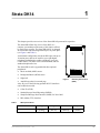
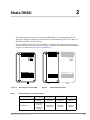
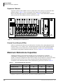
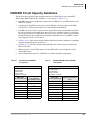
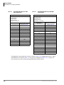
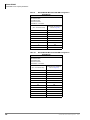
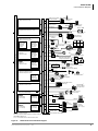
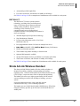
1
Toshiba America Information Systems, Inc.
Telecommunication Systems Division
Limited Warranty
Toshiba America Information Systems, Inc., (“TAIS”) warrants that this telephone equipment
(except for fuses, lamps, batteries, and other consumables) will, upon delivery by TAIS or an
authorized TAIS dealer to a retail customer in new condition, be free from defects in material and
workmanship for twelve (12) months after delivery. This warranty is void (a) if the equipment is
used under other than normal use and maintenance conditions, (b) if the equipment is modified or
altered, unless the modification or alteration is expressly authorized by TAIS, (c) if the equipment
is subject to abuse, neglect, lightning, electrical fault, or accident, (d) if the equipment is repaired
by someone other than TAIS or an authorized TAIS dealer, (e) if the equipment’s serial number is
defaced or missing, or (f) if the equipment is installed or used in combination or in assembly with
products not supplied by TAIS and which are not compatible or are of inferior quality, design, or
performance.
The sole obligation of TAIS or Toshiba Corporation under this warranty, or under any other legal
obligation with respect to the equipment, is the repair or replacement by TAIS or its authorized
dealer of such defective or missing parts as are causing the malfunction with new or refurbished
parts (at their option). If TAIS or one of its authorized dealers does not replace or repair such parts,
the retail customer’s sole remedy will be a refund of the price charged by TAIS to its dealers for
such parts as are proven to be defective, and which are returned to TAIS through one of its
authorized dealers within the warranty period and no later than thirty (30) days after such
malfunction, whichever first occurs.
Under no circumstances will the retail customer or any user or dealer or other person be entitled to
any direct, special, indirect, consequential, or exemplary damages, for breach of contract, tort, or
otherwise. Under no circumstances will any such person be entitled to any sum greater than the
purchase price paid for the item of equipment that is malfunctioning.
To obtain service under this warranty, the retail customer must bring the malfunction of the
machine to the attention of one of TAIS’ authorized dealers within the twelve (12) month period
and no later than thirty (30) days after such malfunction, whichever first occurs. Failure to bring
the malfunction to the attention of an authorized TAIS dealer within the prescribed time results in
the customer being not entitled to warranty service.
THERE ARE NO OTHER WARRANTIES FROM EITHER TOSHIBA AMERICA
INFORMATION SYSTEMS, INC., OR TOSHIBA CORPORATION WHICH EXTEND
BEYOND THE FACE OF THIS WARRANTY. ALL OTHER WARRANTIES, EXPRESS OR
IMPLIED, INCLUDING THE WARRANTIES OF MERCHANTABILITY, FITNESS FOR A
PARTICULAR PURPOSE, AND FITNESS FOR USE, ARE EXCLUDED.
No TAIS dealer and no person other than an officer of TAIS may extend or modify this warranty.
No such modification or extension is effective unless it is in writing and signed by the vice
president and general manager, Telecommunication Systems Division.
726+,%$
Telecommunication Systems Division
Digital Business Telephone Solutions
General Description
Software Release 3.1
Software Release 4.3
Software Release 4.3 and ACD
June 2000
Strata DK
General End User Information
The Strata DK Digital Business Telephone System is registered in accordance with the
provisions of Part 68 of the Federal Communications Commission’s Rules and
Regulations.
FCC Requirements
Means of Connection: The Federal Communications Commission (FCC) has
established rules which permit the Strata DK system to be connected directly to the
telephone network. Connection points are provided by the telephone company—
connections for this type of customer-provided equipment will not be provided on coin
lines. Connections to party lines are subject to state tariffs.
Incidence of Harm: If the system is malfunctioning, it may also be disrupting the
telephone network. The system should be disconnected until the problem can be
determined and repaired. If this is not done, the telephone company may temporarily
disconnect service. If possible, they will notify you in advance, but, if advance notice is
not practical, you will be notified as soon as possible. You will be informed of your
right to file a complaint with the FCC.
Service or Repair: For service or repair, contact your local Toshiba telecommunications
distributor. To obtain the nearest Toshiba telecommunications distributor in your area,
call Toshiba America Information Systems, Inc., Telecommunication Systems Division
in Irvine, CA (949) 583-3700.
Telephone Network Compatibility: The telephone company may make changes in its
facilities, equipment, operations, and procedures. If such changes affect the
compatibility or use of the Strata DK system, the telephone company will notify you in
advance to give you an opportunity to maintain uninterrupted service.
Notification of Telephone Company: Before connecting a Strata DK system to the
telephone network, the telephone company may request the following:
1. Your telephone number.
2. FCC registration number:
♦ Strata DK may be configured as a Key or Hybrid telephone system. The
appropriate configuration for your system is dependent upon your operation of
the system.
♦ If the operation of your system is only manual selection of outgoing lines, it may
be registered as a Key telephone system.
♦ If your operation requires automatic selection of outgoing lines, such as dial
access, Least Cost Routing, Pooled Line Buttons, etc., the system must be
registered as a Hybrid telephone system. In addition to the above, certain
features (tie Lines, Off-premises Stations, etc.) may also require Hybrid
telephone system registration in some areas.
♦ If you are unsure of your type of operation and/or the appropriate FCC
registration number, contact your local Toshiba telecommunications distributor
for assistance.
DK14 and DK40i
Key system: CJ6MLA-74479-KF-E
Hybrid: CJ6MLA-74478-MF-E
DK424i
Key system: CJ69XA-10242-KF-E
Hybrid: CJ69XA-10243-MF-E
PBX: CJ6JPN-22758-PF-E
3. Ringer equivalence number: 0.3B. The ringer equivalence number (REN) is useful
to determine the quantity of devices which you may connect to your telephone line
and still have all of those devices ring when your number is called. In most areas,
but not all, the sum of the RENs of all devices connected to one line should not
exceed five (5.0B). To be certain of the number of devices you may connect to your
line, as determined by the REN, you should contact your local telephone company
to ascertain the maximum REN for your calling area.
4. Network connection information USOC jack required: RJ1CX, RJ2EX, RJ2GX,
RJ48C, RJ48X, RJ11, RJ14C, RJ21X (see Network Requirements in this
document). Items 2, 3 and 4 are also indicated on the equipment label.
Radio Frequency Interference
Warning: This equipment generates, uses, and can radiate radio frequency energy and if
not installed and used in accordance with the manufacturer’s instruction manual, may
cause interference to radio communications. It has been tested and found to comply
with the limits for a Class A computing device pursuant to Subpart J of Part 15 of FCC
Rules, which are designed to provide reasonable protection against such interference
when operated in a commercial environment. Operation of this equipment in a
residential area is likely to cause interference, in which case, the user, at his/her own
expense, will be required to take whatever measures may be required to correct the
interference.
This system is listed with Underwriters Laboratory.
UL Requirement: If wiring from any telephone exits the building or is
subject to lightning or other electrical surges, then secondary protection
is required. Secondary protection is also required on DID, OPS, and tie
lines. (Additional information is provided in this manual.)
In accordance with U.S. Copyright Law, a license may be required from
the American Society of Composers, Authors and Publishers, or other similar
organization, if radio or TV broadcasts are transmitted through the music-on-hold
feature of this telecommunication system. Toshiba America Information Systems, Inc.,
hereby disclaims any liability arising out of the failure to obtain such a license.
CP01, Issue 8, Part I Section 14.1
Notice: The Industry Canada label identifies certified equipment. This certification
means that the equipment meets certain telecommunications network protective,
operational and safety requirements as prescribed in the appropriate Terminal
Equipment Technical Requirements document(s). The Department does not guarantee
the Equipment will operate to the user’s satisfaction.
Before installing this equipment, users should ensure that it is permissible to be
connected to the facilities of the local telecommunications company. The equipment
must also be installed using an acceptable method of connection. The customer should
be aware that compliance with the above conditions may not prevent degradation of
service in some situations.
Repairs to certified equipment should be coordinated by a representative designated by
the supplier. Any repairs or alterations made by the user to this equipment, or
equipment malfunctions, may give the telecommunications company cause to request
the user to disconnect the equipment.
Users should ensure for their own protection that the electrical ground connections of
the power utility, telephone lines and internal metallic water pipe system, if present, are
connected together. This precaution may be particularly important in rural areas.
CAUTION!
Users should not attempt to make such connections themselves, but
should contact the appropriate electric inspection authority, or
electrician, as appropriate.
CP01, Issue 8, Part I Section 14.2
Notice: The Ringer Equivalence Number (REN) assigned to each terminal device
provides an indication of the maximum number of terminals allowed to be connected to
a telephone interface. The terminal on an interface may consist of any combination of
devices subject only to the requirement that the sum of the Ringer Equivalence
Numbers of all the Devices does not exceed 5.
© Copyright 2000
Toshiba America Information Systems, Inc., Telecommunication Systems Division,
reserves the right, without prior notice, to revise this information publication for any
reason, including, but not limited to, utilization of new advances in the state of
technical arts or to simply change the design of this document.
Toshiba America Information Systems, Inc.
Telecommunication Systems Division
DKA-GD-GNDES-VF
4010451
Version F.2, June 2000
Version F.1, May 2000
Version F, May 2000 (Release 4.3)
Version E.2, March 2000 (Release 4.15)
Version E, May 1999
Version D, August 1998
Version C, March 1998
Version B, October 1997
Version A.1, May 1997
Version A, March 1997
®
Important Notice — Music-On-Hold
Publication Information
Further, Toshiba America Information Systems, Inc., Telecommunication Systems
Division, also reserves the right, without prior notice, to make such changes in
equipment design or components as engineering or manufacturing methods may
warrant.
UL
All rights reserved. No part of this manual, covered by the copyrights hereon, may be
reproduced in any form or by any means—graphic, electronic, or mechanical,
including recording, taping, photocopying, or information retrieval systems—without
express written permission of the publisher of this material.
Strata AirLink and Call Center Viewer are trademarks of Toshiba America Information
Systems, Inc. Stratagy is a registered trademark of Toshiba America Information
Systems, Inc. Strata is a registered trademark of Toshiba Corporation.
Trademarks, registered trademarks, and service marks are the property of their
respective owners.
Contents
Introduction
Organization........................................................................................................................................... ix
Conventions............................................................................................................................................. x
Related Documents/Media ..................................................................................................................... xi
General Descriptions ....................................................................................................................... xi
Installation and Programming ......................................................................................................... xi
Feature Description.......................................................................................................................... xi
User Guides for:............................................................................................................................... xi
Quick Reference Guides for: ..........................................................................................................xii
CD-ROMs.......................................................................................................................................xii
Chapter 1 – Strata DK14
KSU Architecture.................................................................................................................................... 2
Digital Telephone/Central Office (CO) Line Circuits...................................................................... 2
Optional Printed Circuit Boards.............................................................................................................. 3
Central Office Line/Digital Telephone Interface Unit (QCDU2) .................................................... 3
Standard Telephone Interface Unit (QSTU2)................................................................................... 3
DTMF Receiver/ABR Tone Detector Unit (QRCU3)...................................................................... 3
Auto Attendant Feature Key (QKYS1) ............................................................................................ 3
Serial Interface Board (WSIU1) ....................................................................................................... 3
Power Considerations.............................................................................................................................. 4
Reserve Power .................................................................................................................................. 4
Power Failure Interface .................................................................................................................... 4
Music-on-Hold (MOH) Interface ..................................................................................................... 4
Paging Interface................................................................................................................................ 4
Flexible Relay Contacts.................................................................................................................... 4
Maximum Line/Station Configurations .................................................................................................. 5
Network Requirements............................................................................................................................ 5
Functional Block Diagram ...................................................................................................................... 6
System Technology................................................................................................................................. 7
Pulse Code Modulation .................................................................................................................... 7
Custom Electronic Circuitry............................................................................................................. 7
Stored Program Control.................................................................................................................... 7
Microprocessors................................................................................................................................ 7
Maintenance and Programming .............................................................................................................. 8
DKi Admin/DKi Backup .................................................................................................................. 8
Strata DK General Description
6/00
i
Contents
Chapter 2 – Strata DK40i
Chapter 2 – Strata DK40i
Base KSU Architecture ......................................................................................................................... 10
Digital Telephone Circuits.............................................................................................................. 10
Central Office (CO) Line Circuits (TCOU/TDDU/TBSU/TBUU)................................................ 10
Standard Telephone Interface Unit (KSTU2)................................................................................. 11
DTMF/ABR Tone Detection Receiver (K5RCU and K5RCU2) ................................................... 11
Feature Key (KKYS) ...................................................................................................................... 12
SMDR, SMDI, ACD/MIS and Maintenance DKi Admin/Modem (TTY) Interface (TSIU) ......... 12
Expansion KSU Architecture................................................................................................................ 12
Station and Line Capacities................................................................................................................... 12
ISDN BRI Lines ............................................................................................................................. 13
Peripherals............................................................................................................................................. 14
Power Considerations............................................................................................................................ 15
Power Supply/Reserve Power ........................................................................................................ 15
Power Failure Interface .................................................................................................................. 16
Music-on-Hold Interface ................................................................................................................ 16
Functional Block Diagram .................................................................................................................... 16
Network Requirements.......................................................................................................................... 18
System Technology............................................................................................................................... 18
Pulse Code Modulation .................................................................................................................. 18
Custom Electronic Circuitry........................................................................................................... 18
Stored Program Control.................................................................................................................. 18
Microprocessors.............................................................................................................................. 18
Maintenance and Programming ............................................................................................................ 18
DKi Admin/DKi Backup ................................................................................................................ 18
StrataControl................................................................................................................................... 18
Chapter 3 – Strata DK424i
Architecture........................................................................................................................................... 19
Processor PCBs ..................................................................................................................................... 20
Processor PCB Subassemblies........................................................................................................ 20
Cabinet Slots ......................................................................................................................................... 21
Base Cabinet ................................................................................................................................... 21
Expansion Cabinets ........................................................................................................................ 22
Printed Circuit Boards (PCBs) ....................................................................................................... 22
Maximum Station/Line Capacities........................................................................................................ 22
ISDN BRI Circuit Capacity Guidelines ................................................................................................ 25
ISDN BRI CIrcuit Capacity Guidelines................................................................................................ 27
Remote Expansion Cabinet Unit........................................................................................................... 30
Power Considerations............................................................................................................................ 30
Reserve Power ................................................................................................................................ 30
Primary/Reserve Power Cabinet Hardware .......................................................................................... 31
DK424 and DK424i Hardware Compatibility ...................................................................................... 34
Functional Block Diagrams................................................................................................................... 35
Maintenance and Programming ............................................................................................................ 38
DKi Admin/DKi Backup ................................................................................................................ 38
StrataControl................................................................................................................................... 38
ii
Strata DK General Description
6/00
Contents
Chapter 4 – Universal Slot PCBs
Chapter 4 – Universal Slot PCBs
Station PCBs ......................................................................................................................................... 39
Digital Telephone Interface Unit (PDKU2) ................................................................................... 39
Digital/Standard Telephone Interface Unit (RDSU) ...................................................................... 39
Strata AirLink Wireless Interface Unit (RWIU) ............................................................................ 40
CO Line/Digital Telephone Interface Unit (KCDU) (DK40i only) ............................................... 40
Electronic Telephone Interface Unit (PEKU) ................................................................................ 40
Standard/Electronic Telephone Interface Unit (PESU).................................................................. 40
Standard Telephone Interface Unit (RSTU2)................................................................................. 40
Console PCBs........................................................................................................................................ 41
Attendant Console Interface Unit (RATU, DK424i only) ............................................................. 41
CO Line PCBs....................................................................................................................................... 41
Caller ID Interface Unit (RCIU2)................................................................................................... 41
Loop Start CO Line Interface Unit (RCOU) .................................................................................. 42
Ground/Loop Start Interface CO Line Interface Unit (RGLU2).................................................... 42
Direct Inward Dialing Interface Unit (RDDU)............................................................................... 42
Tie Line Unit (REMU) ................................................................................................................... 42
Voice Over IP Gateway (BVPU).................................................................................................... 43
T1/DS-1 Interface Unit (RDTU2) .................................................................................................. 43
ISDN Primary Rate Interface Unit (RPTU) ................................................................................... 43
ISDN S/T-type Basic Rate Interface Unit (RBSU) ........................................................................ 43
ISDN U-type Basic Rate Interface Unit (RBUU) .......................................................................... 44
Enhanced 911 CAMA Trunk Interface Unit (RMCU/RCMS)....................................................... 44
Summary of PCBs and Subassemblies ................................................................................................. 45
Option Interface PCBs .......................................................................................................................... 48
Option Interface Unit (PIOU)......................................................................................................... 48
Simplified Option Interface Unit (PIOUS)..................................................................................... 48
External Page Interface Unit (PEPU) ............................................................................................. 48
Single Serial Interface Unit (RSSU)............................................................................................... 48
Serial Interface Unit (RSIU, DK424i only).................................................................................... 49
Option Interface PCB Compatibility .............................................................................................. 50
Chapter 5 – Stations and Peripherals
Digital Telephones ................................................................................................................................ 52
DKT2001 ........................................................................................................................................ 53
Liquid Crystal Display (LCD) Telephones ........................................................................................... 54
Speakerphones....................................................................................................................................... 55
Peripherals............................................................................................................................................. 56
Digital Telephone Upgrade Options ..................................................................................................... 57
Digital Add-on Module (DADM)................................................................................................... 57
Integrated PC Interface (RPCI-DI)................................................................................................. 57
Headset/Loud Ringing Bell Interface (HHEU) .............................................................................. 57
Microphone Unit (RFDM).............................................................................................................. 57
Speaker Off-hook Call Announce (DVSU).................................................................................... 58
Stand-alone Data Interface Unit (PDIU-DS) ........................................................................................ 58
Cordless Digital Telephones ................................................................................................................. 58
DKT2104-CT.................................................................................................................................. 58
DKT2004-CT.................................................................................................................................. 59
Strata AirLink Wireless Handset .......................................................................................................... 59
Strata DK General Description
6/00
iii
Contents
Chapter 6 – System Features
Features........................................................................................................................................... 60
Strata AirLink Wireless Systems.................................................................................................... 60
PC Attendant Console (DK-PCATT).................................................................................................... 61
Direct Station Selection (DSS) Console ............................................................................................... 62
Door Phone (MDFB)............................................................................................................................. 63
Door Phone and Lock Control Unit (DDCB) ....................................................................................... 63
External Speaker (HESB) ..................................................................................................................... 63
Toshiba Stratagy and Stratagy DK Voice Processing........................................................................... 63
Cabling and Connectors ........................................................................................................................ 64
Station and Peripheral Specifications.................................................................................................... 64
Chapter 6 – System Features
Abandoned Call Numbers ..................................................................................................................... 65
Account Codes (Forced/Voluntary/Verified)........................................................................................ 65
Alarm Sensor (DK40i, DK424i only) ................................................................................................... 65
Alternate Answer Point ......................................................................................................................... 66
Amplified Conference Interface (DK40i, DK424i only) ...................................................................... 66
Auto Attendant (Built-in)...................................................................................................................... 66
Automatic Call Distribution (ACD)...................................................................................................... 67
Insight DK ...................................................................................................................................... 67
Automatic Number Identification (ANI) .............................................................................................. 68
Automatic Release from Hold............................................................................................................... 69
Background Music (BGM) ................................................................................................................... 69
Caller ID................................................................................................................................................ 69
Centrex/PBX Compatible...................................................................................................................... 70
Centrex Ringing Repeat ........................................................................................................................ 70
Computer Telephony Integration (CTI) ................................................................................................ 70
Digital Telephone Integrated PC Interface..................................................................................... 70
StrataLink ....................................................................................................................................... 70
Conferencing ......................................................................................................................................... 71
Credit Card Calling ............................................................................................................................... 71
Data Switching ...................................................................................................................................... 71
Day/Night Modes .................................................................................................................................. 72
Delayed Ringing.................................................................................................................................... 72
Dialed Number Identification Service (DNIS)
(DK40i, DK424i only).................................................................................................................... 72
External Telephone Network Numbers .......................................................................................... 73
Voice Mail ...................................................................................................................................... 73
Direct Inward Dialing (DID) Lines (DK40i, DK424i only) ................................................................. 73
Direct Inward System Access (DISA) .................................................................................................. 73
Distinctive CO Line/Directory Number Ringing.................................................................................. 74
Door Lock Control ................................................................................................................................ 74
Door Phones (MDFB) ........................................................................................................................... 74
DTMF Back Tone ................................................................................................................................. 74
DTMF and Dial Pulse CO Line Compatible......................................................................................... 74
DTMF Signal Time (80/160 ms)........................................................................................................... 74
Emergency Ringdown........................................................................................................................... 75
Enhanced 911 (E911) Service (DK40i, DK424i only) ......................................................................... 75
Adjunct Equipment Operation........................................................................................................ 75
Direct CAMA Connections ............................................................................................................ 76
iv
Strata DK General Description
6/00
Contents
Chapter 6 – System Features
ISDN Operation.............................................................................................................................. 76
External Page Zones.............................................................................................................................. 76
Flexible Button Assignment.................................................................................................................. 76
Flexible Directory Numbers.................................................................................................................. 76
Flexible Line Ringing Assignment ....................................................................................................... 77
Group Paging ........................................................................................................................................ 77
Handsfree Directory Number Paths ...................................................................................................... 77
Hospitality Management Information System (HMIS)......................................................................... 77
Hotline Service...................................................................................................................................... 78
Integrated Services Digital Network (ISDN)
(DK40i, DK424i only)................................................................................................................... 78
ISDN Primary Rate Interface (PRI)................................................................................................ 79
ISDN Basic Rate Interface (BRI) ................................................................................................... 79
Call-by-Call Service Selection ....................................................................................................... 79
Non-Facility Associated Signaling (NFAS) ................................................................................... 80
Calling Number Identification Services (CNIS) ............................................................................ 80
Least Cost Routing (LCR) .................................................................................................................... 81
Line Groups........................................................................................................................................... 81
Line Queuing......................................................................................................................................... 81
Live System Programming.................................................................................................................... 81
Memory Protection................................................................................................................................ 82
Message Waiting................................................................................................................................... 82
Multiple Directory Numbers ................................................................................................................. 82
Primary Directory Number [PDN] ................................................................................................. 82
Secondary Directory Number [SDN] ............................................................................................. 82
Phantom Directory Number [PhDN].............................................................................................. 83
Multiple FCC Registration.................................................................................................................... 84
Music-on-hold (MOH) .......................................................................................................................... 84
Night Ringing Over External Page ....................................................................................................... 84
Night Ringing Over Selected Page Zones............................................................................................. 84
Non-blocking Talk Paths....................................................................................................................... 84
Off-premises Station ............................................................................................................................. 84
Outgoing Call Restriction ..................................................................................................................... 85
Pooled CO Line Button......................................................................................................................... 85
Power Failure Transfer.......................................................................................................................... 85
Privacy/Non-privacy Calling ................................................................................................................ 85
Relay Service ........................................................................................................................................ 86
External Page/Door Lock Control .................................................................................................. 86
Night Relay/Hold Relay ................................................................................................................. 86
Remote Administration/Maintenance ................................................................................................... 86
Reserve Power....................................................................................................................................... 86
Simplified Message Desk Interface (SMDI)......................................................................................... 86
Better Port Usage............................................................................................................................ 87
Improves Call Coverage ................................................................................................................. 87
Streamlines Messaging Procedures ................................................................................................ 87
Speed Dial ............................................................................................................................................. 87
System Speed Dial.......................................................................................................................... 87
Station Speed Dial .......................................................................................................................... 87
Station Hunting ..................................................................................................................................... 88
Serial Hunt...................................................................................................................................... 88
Strata DK General Description
6/00
v
Contents
Chapter 7 – Station Features
Distributed Hunt (DH).................................................................................................................... 88
Station Message Detail Recording (SMDR) ......................................................................................... 88
Station Relocation ................................................................................................................................. 89
StrataControl ......................................................................................................................................... 89
System Programming through a Station ............................................................................................... 89
System Program Administration Software (DKi Admin)..................................................................... 89
T1 Interface (DK40i, DK424i only)...................................................................................................... 90
Tandem CO Line Connections.............................................................................................................. 90
Tenant Service....................................................................................................................................... 90
Tie Lines................................................................................................................................................ 91
Toll Restriction...................................................................................................................................... 91
Toll Restriction Override by System Speed Dial.................................................................................. 91
Traveling Class of Service .................................................................................................................... 91
Unrestricted Call Transfer to Directory Numbers................................................................................. 92
Voice First or Tone Signaling ............................................................................................................... 92
Voice Mail Integration .......................................................................................................................... 92
Automated Attendant...................................................................................................................... 92
ANI/DNIS Routing to Voice Mailbox............................................................................................ 92
Call Forward to Voice Mailbox...................................................................................................... 92
Message Waiting Indication ........................................................................................................... 93
Voice Mail Control via Station....................................................................................................... 93
Chapter 7 – Station Features
Account Code Button............................................................................................................................ 97
Add-on Module (DADM) ..................................................................................................................... 97
Alert Signal Button ............................................................................................................................... 97
Automatic Busy Redial (ABR) ............................................................................................................. 97
Automatic Callback (ACB)................................................................................................................... 98
Automatic Hold..................................................................................................................................... 98
Automatic Line Selection...................................................................................................................... 98
Background Music (BGM) with Station Control.................................................................................. 98
Busy Override ....................................................................................................................................... 98
Busy Station Transfer/Busy Station Ringing ........................................................................................ 98
Call Forwarding .................................................................................................................................... 99
All Calls.......................................................................................................................................... 99
Busy ................................................................................................................................................ 99
No Answer...................................................................................................................................... 99
Busy/No Answer............................................................................................................................. 99
Fixed ............................................................................................................................................. 100
External Call ................................................................................................................................. 100
Call Park Orbits................................................................................................................................... 100
Park and Page ............................................................................................................................... 100
Auto Park...................................................................................................................................... 100
Call Pickup .......................................................................................................................................... 100
Call Pickup Groups ............................................................................................................................. 101
Call Transfer with Camp-on................................................................................................................ 101
Call Transfer Immediate ..................................................................................................................... 101
Call Transfer Music or Ringing Option .............................................................................................. 101
Call Transfer Recall ............................................................................................................................ 101
Centrex/PBX Features......................................................................................................................... 101
vi
Strata DK General Description
6/00
Contents
Chapter 8 – PC Attendant Console Features
Conferencing ....................................................................................................................................... 102
Continuous Dual-tone Multi-frequency (DTMF) Tone ...................................................................... 102
Data Call Button.................................................................................................................................. 102
Direct Station Selection (DSS) Buttons .............................................................................................. 102
Direct Station Selection (DSS) Console Features............................................................................... 102
Directory Number [DN] Buttons ........................................................................................................ 103
DISA Security Code Revision ............................................................................................................ 103
Distinctive LED Color and Flash Indications ..................................................................................... 103
Distinctive Station Ringing ................................................................................................................. 103
Do Not Disturb (DND)........................................................................................................................ 103
Do Not Disturb (DND) Override ........................................................................................................ 103
DP/DTMF Mode Change.................................................................................................................... 103
Exclusive Hold .................................................................................................................................... 103
Executive Override.............................................................................................................................. 104
Feature Prompting with Soft Keys...................................................................................................... 104
Flash Button ........................................................................................................................................ 104
Handsfree Answerback ....................................................................................................................... 104
Hearing Aid Compatible ..................................................................................................................... 104
Liquid Crystal Display (LCD) Features.............................................................................................. 104
Microphone Cut-off Button................................................................................................................. 104
Microphone (External Unit)................................................................................................................ 105
Modem Button .................................................................................................................................... 105
Modular Handset and Line Cords ....................................................................................................... 105
Modular Headset ................................................................................................................................. 105
Off-hook Call Announce (OCA)......................................................................................................... 105
Handset Mode............................................................................................................................... 105
Speaker Mode ............................................................................................................................... 106
On-hook Dialing.................................................................................................................................. 106
Personal Computer Interface (RPCI-DI)............................................................................................. 106
Pooled Line Buttons............................................................................................................................ 106
Private CO Lines ................................................................................................................................. 106
Push-button Dialing ............................................................................................................................ 106
Release Button .................................................................................................................................... 106
Release/Answer Button....................................................................................................................... 107
Remote Retrieval of Held/Parked Calls .............................................................................................. 107
Repeat Last Number Dialed ................................................................................................................ 107
Ringing Line Preference ..................................................................................................................... 107
Saved Number Redial ......................................................................................................................... 107
Speed Dial Buttons.............................................................................................................................. 107
Telephone Application Programming Interface (TAPI) Compatibility .............................................. 108
Timed Reminders ................................................................................................................................ 108
Toll Restriction Override Code Revision............................................................................................ 108
User Programmable Feature Buttons .................................................................................................. 108
Chapter 8 – PC Attendant Console Features
Answer Button .................................................................................................................................... 113
Answer Priority ................................................................................................................................... 113
Answer Prompting .............................................................................................................................. 113
Attendant Conference Setup ............................................................................................................... 114
Auto Day/Night Mode Switching ....................................................................................................... 114
Strata DK General Description
6/00
vii
Contents
Chapter 8 – PC Attendant Console Features
Auto Dialing........................................................................................................................................ 114
Busy Lamp Field (BLF) Display......................................................................................................... 114
Call Waiting Count ............................................................................................................................. 114
Color CRT Display ............................................................................................................................. 114
Dial “O” For Attendant ....................................................................................................................... 114
Dial Outside Number For Station User............................................................................................... 114
Direct Station Selection (DSS)............................................................................................................ 115
Directory Display and Dialing ............................................................................................................ 115
DTMF Signaling from Dial Pad.......................................................................................................... 115
Emergency Calls ................................................................................................................................. 115
Emergency Page.................................................................................................................................. 115
Feature On-Line Help ......................................................................................................................... 115
Feature Prompting with Soft Keys...................................................................................................... 115
Flexible Programmable Buttons.......................................................................................................... 116
Headset Operation............................................................................................................................... 116
Hold Button......................................................................................................................................... 116
Hold Timer Display............................................................................................................................. 116
Incoming Call Identification ............................................................................................................... 116
Incoming Call Statistics ...................................................................................................................... 116
Interposition Call Transfer .................................................................................................................. 116
Join Button .......................................................................................................................................... 116
Keyboard or Mouse Operation............................................................................................................ 117
Load Sharing ....................................................................................................................................... 117
Loop Hold Display.............................................................................................................................. 117
Message Center ................................................................................................................................... 117
Multi-tasking ....................................................................................................................................... 117
Name or Number Dialing.................................................................................................................... 118
Overflow ............................................................................................................................................. 118
Override............................................................................................................................................... 118
Position Busy Mode ............................................................................................................................ 118
Release Button .................................................................................................................................... 118
Speed Dial Calling .............................................................................................................................. 118
Split/Switch Button ............................................................................................................................. 119
Three-way Calling............................................................................................................................... 119
Through Dialing .................................................................................................................................. 119
Transfer Direct to Voice Mail ............................................................................................................. 119
Trunk Group Busy Indication ............................................................................................................. 119
Trunk Group Control........................................................................................................................... 119
Volume Control................................................................................................................................... 119
Appendix – General Specifications ......................................................................................... 121
Network Requirements........................................................................................................................ 122
Customer-supplied Peripherals and Interfaces.................................................................................... 124
Station Specifications.......................................................................................................................... 125
Glossary ............................................................................................................................................... 131
Index ........................................................................................................................................................ 135
viii
Strata DK General Description
6/00
Introduction
This General Description provides an overview of the Strata DK telephone systems, associated
hardware, system and station features. These systems include:
♦
Strata DK14
♦
Strata DK40i
♦
Strata DK424i
Organization
This document is divided into the following major topics:
♦
Chapter 1 – Strata DK14 describes the Strata DK14 overall system and covers the basics of:
capacities, system expansion and configuration, power requirements, technology, and
maintenance.
♦
Chapter 2 – Strata DK40i describes the overall system and the basic capacities, system
expansion and configuration, power requirements, technology, and maintenance.
♦
Chapter 3 – Strata DK424i describes this new system and covers basic capacities, system
expansion and configuration, technology, power requirements, maintenance, and
programming.
♦
Chapter 4 – Universal Slot PCBs provides information about Printed Circuit Boards (PCBs)
that can be installed in the universal slots of the Strata DK systems.
♦
Chapter 5 – Stations and Peripherals describes the most recent Toshiba-proprietary stations
and peripherals, customer-supplied peripherals, as well as cabling and connectors. Includes
information on system tones and data interface specifications.
♦
Chapter 6 – System Features describes the features which are available system-wide.
♦
Chapter 7 – Station Features describes the features which are available as stations features
and shows the types of stations on which they are available.
♦
Chapter 8 – PC Attendant Console Features describes the features available from a PC
Attendant Console, digital telephones, and the older DK Attendant Console.
♦
Appendix – Specifications contains reference information for the DK14, DK40i, and DK424i
systems and compatible stations.
Strata DK General Description
6/00
ix
Introduction
Conventions
Conventions
Conventions
Note
Important!
Description
Elaborates specific items or references other information. Within some
tables, general notes apply to the entire table and numbered notes apply to
specific items.
Calls attention to important instructions or information.
[DN]
Represents any Directory Number button, also known as an extension or
intercom number.
[PDN]
Represents any Primary Directory Number button (the extension number for
the telephone).
[SDN]
Represents any Secondary appearance of a PDN. A PDN which appears on
another telephone is considered an SDN.
[PhDN]
Represents any Phantom Directory Number button (an additional DN).
[]
Brackets indicate a variable button. Example: [DN] represents the actual
Directory Number, such as [301].
$ULDO%ROG
Represents telephone buttons.
Courier
Shows a computer keyboard entry or screen display.
shows a multiple PC keyboard or phone button entry. Entries without spaces
between them show a simultaneous entry.
+
Example: Delete+Enter.
Entries with spaces between them show a sequential entry.
Example: + .
Tilde (~)
See Figure 10
x
Means “through.” Example: 350~640 Hz frequency range.
Grey words within the printed text denote cross-references. In the electronic
version of this document (Strata DK Library CD-ROM or FYI Internet
download), cross-references appear in blue hypertext.
Strata DK General Description
6/00
Introduction
Related Documents/Media
Related Documents/Media
Note
Some documents listed here may appear in different versions on the CD-ROM, FYI, or in
print. To find the most current version, check the version/date in the Publication
Information on the back of the document’s title page.
General Descriptions
♦
Strata DK Call Center Solutions General Description
♦
Hospitality Management Information System (HMIS) General Description
Installation and Programming
♦
Strata DK Installation & Maintenance Manual
♦
Strata DK Programming Manual
♦
Strata AirLink Wireless Systems Installation Guide
♦
Hospitality Management Information System (HMIS) Installation Guide
♦
Insight DK Installation Guide
♦
Voice Over Internet Protocol Installation & Maintenance Manual
Feature Description
♦
Strata DK Feature Description Manual
User Guides for:
♦
Digital Telephone
♦
Digital Single Line Telephone
♦
Electronic Telephone
♦
Standard Telephone
♦
DKT2004-CT Cordless Telephone
♦
DKT2104-CT Cordless Telephone
♦
Strata AirLink External Wireless Handset
♦
Strata AirLink Integrated Wireless Handset
♦
PC/Data Interface
♦
System Administrator Guide
♦
PC Attendant Console
♦
Hospitality Management Information System (HMIS)
♦
Call Center Viewer
♦
Insight DK Supervisor Guide
♦
ACD Agent Guide
♦
ACD Supervisor Guide
Strata DK General Description
6/00
xi
Introduction
Related Documents/Media
♦
Software MIS (SMIS) Supervisor Manual
♦
Keyprint 2000
Quick Reference Guides for:
♦
Digital Telephone
♦
Electronic Telephone
♦
Strata AirLink External Wireless
♦
Strata AirLink Integrated Wireless
♦
PC Attendant Console
♦
Insight DK inView
CD-ROMs
♦
Strata DK Library
♦
Strata DK HMIS
♦
StrataControl
♦
DKi Quote
♦
DKi Admin/DKi Backup
♦
Strata DK424 Insight DK (Insight works with the DK424i also)
Note
xii
For authorized users, Internet site FYI (http://fyi.tsd.toshiba.com) contains all Strata DK
documentation and enables you to view, print, and download current publications.
Strata DK General Description
6/00
1
Strata DK14
This chapter provides an overview of the Strata DK14 System and its capacities.
The Strata DK14 Base Key Service Unit (KSU) is a
compact system that provides many of the features offered
by much larger systems. The Strata DK14 KSU is designed
for convenient wall-mounting and occupies very little space
(see Figure 1 and Table 1).
AC
DC
At maximum configuration, the Strata DK14 provides up to
10 station ports, that can be used for up to eight digital
telephones (including the cordless telephone), up to four
Central Office (CO) lines can be accommodated, and two
standard telephone devices.
The Strata DK14 can be upgraded with these optional
peripherals:
♦
Music-on-hold (MOH) source
♦
Background Music (BGM) source
♦
Night bell
♦
Amplifier/speaker for external page
2186
Figure 1
Base Key Service Unit
(KSU)
Also, any two of the following optional RS-232 interfaces
can be added as needed:
Table 1
♦
Caller ID (CLID)
♦
Station Message Detail Reporting (SMDR)
♦
Simplified Message Desk Interface (SMDI) for Voice Mail
♦
DKi Admin (TTY) Interface
KSU Specifications
Unit
Key Service Base Unit
Strata DK General Description
6/00
Weight
Height
Width
Depth
5.7 lbs.
(2.59 kg)
16.4 inches
(416 mm)
10.0 inches
(254 mm)
3.0 inches
(76 mm)
1
Strata DK14
KSU Architecture
KSU Architecture
The Strata DK14 KSU contains the main processor, operating software, circuitry and the following
components (see Figure 2).
WARNING
Hazardous voltage inside !
If servicing required,
remove A.C. cord.
HPFB6
BATT
1 or 2
HPFB reserve
power units
DC
AC
DC
J4
SIO 2
J3
J20
J2
J21
SIO 1
WSIU1A
6-wire RJ11
Modular Jack
QRCU3A
Component Side
J1
J10
J6
J8
J7
J5
0 PAD 3
J4
J14
STU
SW101
J1
J11
STU
F.G.
CO4
QCDU2A
J1
J9
SW1
J13
J3
STU
0 PAD 3
QSTU2A
190 130
6-wire RJ11
Modular Jacks
CO1
QKYS
SW101
J6-25 Pair
Amphenol Jack
(female) for
Telephone
Tip/Ring and
Relay Contact
J1
J15
QSTS2A
QSTS1A
CO2
F.G.
CO3
PFT, RJ11
Modular
Jack
QCDU2A
J12
J2
STU
System
Frame
Ground
Bar
VR701
J22
2364
MOH
Jack
Figure 2
600
ohm
Page
MOH
Volume
Control
Not
Used
KSU Interior
Digital Telephone/Central Office (CO) Line Circuits
The main PCB (WMAU) has four integrated circuits that can connect to digital corded and/or
cordless telephones, stand-alone data interface units (PDIU-DSs), and digital door phone/lock
control units (DDCB). Each of the digital telephones can support a PC Data Interface Unit (RPCIDI) or up to two Add-on Modules (DADMs). It does not support a DDSS console.
Two circuits for loop start CO lines are built into the main PCB. Each line can be programmed for
Dual-tone Multi-frequency (DTMF) or dial pulse signaling. It includes a switch to control
potential excess volume from a nearby private branch exchange (PBX) or CO. Built-in gas tubes
help protect each circuit from lightning. Each line supports Caller ID when optional equipment is
added.
2
Strata DK General Description
6/00
Strata DK14
Optional Printed Circuit Boards
Optional Printed Circuit Boards
Central Office Line/Digital Telephone Interface Unit (QCDU2)
The QCDU2 provides one loop start CO line circuit and two digital telephone circuits. It interfaces
with digital corded and/or cordless telephones, RPCI-DIs, ADMs connected to the corded
telephones and PDIU-DSs, and door phones. The DK14 supports up to six door phones. It does not
support a DDSS console. Up to two QCDU2 PCBs can be added to the DK14. Each line supports
Caller ID when optional equipment is added.
Standard Telephone Interface Unit (QSTU2)
The QSTU2 provides two standard telephone circuits for two-wire devices such as standard
telephones, Auto Attendant devices, alternate BGM source connection, voice mail machines, and
facsimile machines.
DTMF Receiver/ABR Tone Detector Unit (QRCU3)
The QRCU3 enables the Strata DK14 to recognize Dual-Tone Multi-Frequency (DTMF) tones
generated by a standard telephone or any other device connected to a QSTU3 standard telephone
circuit. It is also required for Direct Inward System Access (DISA) calls and built-in Auto
Attendant. The QRCU3 enables busy tone detection for Automatic Busy Redial.
Auto Attendant Feature Key (QKYS1)
The QKYS1 plugs into the QRCU3 option PCB to support built-in Auto Attendant.
Serial Interface Board (WSIU1)
The WSIU1 provides two serial interface ports for up to two of the following devices:
♦
Caller ID interface box
♦
SMDR Call Accounting device
♦
SMDI Voice Mail Interface
♦
PC with DKi Admin or external modem
Strata DK General Description
6/00
3
Strata DK14
Power Considerations
Power Considerations
The power supply generates +5VDC and +24VDC for the entire system (see Table 2).
Table 2
DK14 Electrical Characteristics
DK14 Primary Power
115VAC±10V
50/60 Hz
46 watts maximum
<0.7 amps. max
Input AC
AC frequency
Power
AC input current
Power Supply
+24VDC (+26.3~-27.8VDC)
+5VDC (+4.5~+5.5VDC)
DC voltage output specification
Reserve Power
One or two optional Reserve Power Battery and Chargers (HPFBs) can be connected to the Strata
DK14 power supply to maintain normal operation during a power failure. The estimated battery
time for one or two HPFBs is shown below.
DK14 (fully-loaded
system)
Estimated Battery
Time (hours)
One HPFB
0.5~1.0
Two HPFBs
1.0~2.0
Notes
●
Reserve power time varies with system call traffic.
●
AC power must be available when HPFB is first installed.
●
HPFB recharge time is 48 hours per HPFB.
Power Failure Interface
The Strata DK14 KSU provides an interface for a dedicated backup standard telephone during an
AC input power failure. If the system AC input power fails, the backup telephone will
automatically connect to the CO1 line. This feature is independent of the HPFB.
Music-on-Hold (MOH) Interface
Customers can connect their own MOH source to this interface. The source can also feed external
page speakers and telephone speakers with Background Music (BGM).
Paging Interface
This 600-ohm interface can support a Toshiba External Speaker (HESB) or a customer-supplied
amplifier and speaker for Paging, Night Ringing over Page, and BGM applications.
Flexible Relay Contacts
A relay contact can be programmed to either mute BGM during a page announcement over
external speakers, to operate a device—such as an answering machine or ringing bell—during the
Night Mode, or to provide on-off control for a MOH source.
4
Strata DK General Description
6/00
Strata DK14
Maximum Line/Station Configurations
Maximum Line/Station Configurations
The maximum line and station configurations for DK14 are shown in Table 3.
Table 3
CO Lines and Station Ports
CO Line Ports
Digital Ports
Standard
Telephone Ports1
Basic KSU
2
4
0 or 2
Expanded KSU
3
6
0 or 2
Expanded KSU
4
8
0 or 2
DK14 System
1. Standard telephone ports do not support MW lamps on standard telephones.
Network Requirements
Network requirements of station/line PCBs and interface cards are summarized in Table 43 on
Page 122.
Strata DK General Description
6/00
5
Strata DK14
Functional Block Diagram
Functional Block Diagram
Figure 3 shows the Strata DK14 KSU PCBs and the available lines, stations and peripherals. Basic
voltage and cabling information is also included.
115 ± 10VAC (0.7 AMP)
50/60 Hz
DK14 Key Service Unit
AC Input
HPFB
QPSU8A2 Power Supply
Battery
and Charger
(first)
Battery Connector
1
1
600Ω
RCA Jacks
HPFB
AMP
Page
Output
Speaker
1
MOH/BGM Source
Battery
and Charger
(second)
QRCU3A
(optional)
DTMF/ABR
Receivers (3)
Digital Telephone
and Add-on Module
QKYS1A
Note One or two optional HPFB
reserve power units may be
installed.
(optional)
Auto
Attendant
Feature Key
Digital Telephone
KSU Main Circuit Board
DDCB
(standard)
4 — Digital Telephone CKTS
2 — Loop CO Line CKTS
Power Failure
Telephone 1
MDFB
Door Phones and Lock Control
Relay
Contact
PFT
1
X
Loop Start Lines
• FIC: 02LS2
• REN: 0.3 B
Line 1
RJ11C/
RJ21X
CO1
Line 2
RJ11C
Modular Jack
Night Bell, BGM Mute, or
MOH (Control Relay)
CO2
QCDU2A (first/optional)
Digital Telephone
and Add-on Module
2 — Digital Telephone CKTS
1 — Loop CO Line CKT
Central Office/
Centrex/PBX
Line 3
CO3, RJ11C
1
Digital Telephone
With RPCI
QCDU2A (second/optional)
2 — Digital Telephone CKTS
1 — Loop CO Line CKT
Line 4
CO4, RJ11C
Stand-alone
Data Interface
DIU
QSTU2A (optional)
Shared
Printer
2 — Standard
Telephone CKTS
Standard Telephone
POWER
Caller ID Interface
1
Box (TC-1041)
RJ14C
1
TOSHIBA
READY
CONNECT
TOSHIBA
1
1
FAX
117 VAC
WSIU (optional)
DKi Admin, SMDR, SMDI
or CLID Interface CKT
25-pair Amphenol Connector
1
3-pair Modular Interface
RS-232 Port 1
RS-232 Port 2
SMDR
Printer
TOSHIBA
2419
1. Customer-supplied equipment
Figure 3
6
Functional Block Diagram
Strata DK General Description
6/00
Strata DK14
System Technology
System Technology
Pulse Code Modulation
Digital switching talkpaths enable all CO and intercom lines to be accessed simultaneously.
Analog-to-digital and digital-to-analog conversion is done by CODECs (coder plus decoder) on
station and CO line PCBs.
Custom Electronic Circuitry
Large Scale Integration (LSI) technology makes the Strata DK14 circuit designs simple and
efficient. Gate arrays using very large scale integration save vast amounts of space by using the
latest technology. More circuitry fits onto smaller PCBs for a more compact system. Widespread
use of CMOS circuits minimizes system power requirements.
Stored Program Control
The system uses a 16-bit microprocessor for stored program control. The Strata DK14 System
operating software is stored on Read Only Memory (ROM), and individual configuration and
custom programming is stored on Random Access Memory (RAM). A lithium battery with a life
span of at least six years preserves RAM in the case of a power failure.
Microprocessors
The system’s main microprocessor is a 16-bit 68000-type that operates at a clock speed of
8 MHz. In addition, some PCBs use 8-bit, TMP90C840-type local microprocessors that run at 10
MHz. This distributed microprocessing architecture is used system wide.
Strata DK General Description
6/00
7
Strata DK14
Maintenance and Programming
Maintenance and Programming
Hardware maintenance and repair procedures describe how to quickly locate, remove, and replace
defective parts and PCBs. System programming can be performed without taking the system outof-service.
On-site programming can be executed with any 20-button proprietary LCD telephone or with a
DKi Admin PC connected to an optional maintenance port.
Off-site programming with DKi Admin, which can help cut costs and save time, is available
through a customer-provided modem connected to the maintenance port.
DKi Admin/DKi Backup
Toshiba DKi Admin Release 4.0 software enables customer data (configuration, station, and
system options) to be downloaded to a PC and stored on a computer disk. The customer data can
be added to, or changed, using the PC independent of the DK System.
The new customer data can then be uploaded to the DK System from the PC, changing customer
program options on-site or remotely over telephone lines and/or modems.
The DKi Backup software program is also available. The program consists of a small subset of
DKi Admin functions which can perform backup, restore and upgrade functions, but cannot edit
customer databases.
8
Strata DK General Description
6/00
2
Strata DK40i
This chapter provides an overview of the Strata DK40i Release 4.3 system and its capacities.
Release 4.3 enables the DK40i to provide Automatic Call Distribution (ACD), E911 CAMA, T1,
ISDN PRI and BRI U and S/T interfaces.
The Strata DK40i Base Key Service Unit (KSU) is a compact system that provides many of the
features offered by much larger systems. The KSU is designed for convenient wall-mounting and
occupies very little space (see Figures 4, 5 and Table 4.)
AC
AC
DC
DC
POWER
POWER
4247
1711
Figure 4
Table 4
Base Key Service Unit (KSU)
Figure 5
KSU with Expansion Unit
KSU and Expansion Unit Specifications
Unit
Weight
Height
Width
Depth
Key Service Base Unit
8.4 lbs.
(3.8 kg)
18.0 inches
(457 mm)
12.2 inches
(310 mm)
3.4 inches
(86 mm)
18.0 inches
(457 mm)
7.8 inches
(198 mm)
3.4 inches
(86 mm)
1 lb. empty
(0.45 kg)
Expansion Unit
Strata DK General Description
4.3 lbs. full
(2.4 kg)
6/00
9
Strata DK40i
Base KSU Architecture
Base KSU Architecture
1
PN2
2
The Strata DK40i Base KSU contains the main processor, operating software, circuitry and the
following components (see Figure 6).
TPSU16A
DC
-
DC POWER
1
AC
MADE IN
-24 Volt Circuit
Breakers
BATT
2
+
POWER SUPPLY ASSEMBLY
MODEL
INPUT: AC127V 2.2A 60 HZ
OUTPUT: -27.3V 2.8A. -27.3V 0.2A
V. 1A 1996-05 00001
TOSHIBA CORPORATION
WARNING
Reserve Power
Battery Jack
Hazardous voltage inside!
If servicing required
remove A. C. plug.
Connect Expansion
Unit TB1 TO FG2
IMPORTANT: DKSUE16A is incompatible with this unit
DKSUET16A or DKSUE40A is required for expansion
FG2
Important Notice
Expansion KSU
Cable Receptacle
OFF
ON
Base Telephone
Tip/Ring and
Relay Contact
TMAU2A
Battery Jumper
Music-on-Hold
Input
4238
Music-on-Hold
Sensitivity Adjustment
Figure 6
Base KSU Interior
Digital Telephone Circuits
The main circuit board (TMAU2) in the Strata DK40i Base KSU has eight integrated circuits that
can connect to Toshiba-proprietary digital telephones (including the cordless telephone), Standalone Data Interface Units (PDIU-DSs), Digital Door Phone/Lock Control Units (DDCB), and
Digital Direct Station Selection Consoles (DDSS).
Furthermore, each of the digital telephones can support a PC Data Interface Unit (RPCI-DI) or up
to two Add-on Modules (DADMs).
Central Office (CO) Line Circuits (TCOU/TDDU/TBSU/TBUU)
The following PCBs can be installed in the DK40i Base KSU:
10
♦
TCOU provides four circuits for loop start CO lines.
♦
TDDU provides four circuits for Direct Inward Dialing (DID) lines
♦
TBSU provides two circuits for BRI lines or stations (see TBSU below)
♦
TBUU provides two BRI U interface circuits for lines or stations
Strata DK General Description
6/00
Strata DK40i
Base KSU Architecture
The CO line interface and DID interface unit can be programmed for DTMF or dial pulse signaling
and each line has a switch to control potential excess volume that could be created by a nearby
PBX or CO. Built-in gas tubes help protect each TDDU and TCOU line from lightning. An
optional RDDU (for DID lines) installed in the Expansion Unit requires an external secondary
protector. DID lines require the optional K5RCU2 tone receiver.
ISDN BRI S/T Circuits (TBSU)
The TBSU PCB provides two Basic Rate Interface (BRI) circuits for DK40i. The TBSU can only
be installed in the DK40i Base KSU.
The TBSU circuits are four-wire S/T type circuits and connect to the PSTN BRI lines using a
dealer-supplied UL-listed Network Terminator unit (NT1). In Canada, the NT-1 must be CSA
certified. On the station side, they can connect to S-type ISDN Terminal Equipment (TE) or
Terminal Adapters (TA).
ISDN BRI U Circuits (TBUU)
DK BRI U interface circuits can be configured to connect to an ISDN line circuit (NT mode, lineside) or to ISDN U-type terminal equipment TE1 or terminal adapters TA (LT mode, station side).
The TBUU provides two BRI-U circuits that can be configured independently for line or station
circuits.
Note
The TBSU and TBUU contains two circuits, each of which reduces the system capacity by
two station ports or two CO lines. If the BRI circuit is configured as a station circuit, the
circuit assumes two station ports. If the BRI circuit is configured as a line circuit, the
circuit assumes two CO lines. BRI lines can be used for voice and data calls.
Caller ID (TCIU2)
An optional Caller ID PCB (TCIU2) can be added to the four-circuit loop start CO line PCB
(TCOU) to provide four Caller ID circuits. Local telephone companies do not provide Caller ID on
DID lines; so the TCIU2 PCB cannot be added to the four-circuit DID PCB (TDDU). Caller ID
can also be added with the RCIU2 and KCDU2. See “Caller ID Interface Unit (RCIU2)” on Page
41 and “Caller ID” on Page 69 for more information.
Standard Telephone Interface Unit (KSTU2)
The optional KSTU2 provides four circuits that can interface with DTMF for rotary dial standard
telephones and other single-line devices, including: Strata AirLink Wireless Base Station Interface
Adapters (BSIAs) and handsets, fax/modems (14.4 bps max.), Voice Mail and Auto Attendant
devices, off-premises stations, alternate BGM source and dictation equipment. These devices may
require that the optional tone receiver (K5RCU or K5RCU2) be installed in the DK40i Base KSU
to interpret the DTMF signals the above devices may transmit.
The KSTU2 does not support message waiting lamps on standard telephones. The RSTU2 must be
installed in the Expansion Unit to support message waiting lamps.
DTMF/ABR Tone Detection Receiver (K5RCU and K5RCU2)
Station users in systems that have the optional K5RCU or K5RCU2 installed can access Automatic
Busy Redial (ABR) and communicate with devices, such as standard telephones or voice mail
machines that require DTMF signaling.
This unit is also required for Direct Inward System Access (DISA) and built-in or external Auto
Attendant operation, as well as for DID and Tie lines. Each K5RCU or K5RCU2 PCB contains
five shared receivers.
Strata DK General Description
6/00
11
Strata DK40i
Expansion KSU Architecture
Feature Key (KKYS)
The system can be upgraded with an optional feature key, the KKYS, which installs onto the
K5RCU PCB in the Base KSU. The KKYS1 provides Automated Attendant (AA); KKYS2
provides AA and ACD; and KKYS3 provides AA and ACD/MIS.
SMDR, SMDI, ACD/MIS and Maintenance DKi Admin/Modem (TTY) Interface
(TSIU)
The TSIU PCB provides two RS-232 interface ports (modular jacks) that allow the DK40i system
to connect to an SMDR Call Accounting device, a DKi Admin PC or external modem for system
maintenance/administration, ACD/MIS reports using Toshiba’s Insight DK software, or an SMDI
interface for Voice Mail. It does not have a built-in modem capability.
Only one TSIU can be installed per DK40i system. When the TSIU PCB is installed, the PIOU can
still be installed for zone paging, control relays, and an SMDR RS-232 interface, built-in (IMDU)
maintenance modem, ACD/MIS processor or VM SMDI or maintenance interface.
Expansion KSU Architecture
Strata DK40i
Base KSU
The optional Expansion KSU, which attaches
easily to the side of the Base KSU, offers four
universal slots that can host a variety of line and
telephone PCBs (see Figure 7). See Chapter 4 –
Universal Slot PCBs for descriptions of PCBs.
Strata DK40i
Expansion KSU
Expansion
PCB Slots
Side
Cover
Expansion Cover
4243
Figure 7
Expansion KSU Interior
Station and Line Capacities
This section shows the maximum basic and CO configurations that are possible with the DK40i.
There is a variety of configuration combinations of digital and standard telephones with CO lines,
including loop start, ground start, Tie, and DID lines. Any loop or ground start CO line can be
equipped with Caller ID.
The DK40i Base KSU comes equipped with eight digital telephone station circuits. One of four
optional PCBs can be added to provide either four loop start or DID lines, or two ISDN BRI S/T or
U circuits. Another optional TCIU2 PCB can be added to the Base KSU loop start line PCB to
provide Caller ID interface. An optional KSTU2 PCB can be added to provide four standard
telephone circuits (ports).
An optional Expansion KSU can be added to the DK40i to increase the system capacity to 28
station ports and 12 CO lines (see Figure 5). A maximum of 28 station ports and 12 CO line
interfaces are allowed in the system (Base KSU plus Expansion KSU). Base capacity is 12 station
ports and 4 CO line or 2 BRI circuit interfaces.
12
Strata DK General Description
6/00
Strata DK40i
Station and Line Capacities
Table 5 shows maximum capacity for a DK40i system. DKi Quote, an auto quote program that
runs on a PC with Microsoft® Windows®, is available from Toshiba to generate DK40i quotes
and configurations. Also, refer to the Strata DK Installation and Maintenance (I&M) Manual,
Chapter 2 – DK40i Configuration, for more information.
Table 5
Maximum CO Lines/Ports and BRI Line and Station Circuits
Maximum
Allowed
Hardware
CO Lines
12
Station Ports
28
BRI Line Circuits
6
BRI Station Circuits
10
Attaining maximum system capacities depends on power consumption of a particular
configuration (see Table 6). Power factor calculations in accordance with the Strata DK I&M
Manual will determine if the maximum capacities in these tables can be reached.
Table 6
DK40i Station and Line Capacities and Universal Printed Circuit Board Slots
Lines and PCB Slots
DK40i
1
41
Universal slots
Stations2
8~282
CO lines – loop start
0, 2, 4, 8 or 123
CO lines – ground start
0, 2, 4, 8 or 123
DID lines (analog)4
0, 2, 4, 8 or 123
Tie lines (analog)3
0, 2, 4, 8 or 123
T1 lines
8 or 12 channels/lines
ISDN BRI line circuits (S/T type and/or U type)
5
ISDN PRI line circuits
2, 4 or 6 circuits (12 B-channels/lines)3
8 or 12 channels/lines
Squared System Maximum (ground/loop lines + stations)
12 lines + 12 stations
Squared System Maximum (Tie/DID lines + stations)
12 lines + 12 stations
1. There are four universal slots in the DK40i expansion unit.
2. Line and station capacities cannot exceed 28 stations and/or 12 CO lines. Incremental capacities depend on the type
of station/line PCBs installed. All increments are not available with all PCB types.
3. Increments vary and depend on the type of line PCBs installed.
4. In the D40i, DID and Tie, lines do not use up station ports as in DK40, R3.1 and the DK424 R3.2. Each BRI line
circuit uses up to two CO lines of system capacity and no station ports.
5. Each S/T type circuit requires an NT-1 device when connected to a Central Office BRI line circuit.
The DK40i Base and Expansion cabinets provide an extensive number of features for a telephone
system of its size. See Table 40 on Page 109 for a list of DK40i, Release 4.3 features and
capacities.
ISDN BRI Lines
Stations can be a combination of ISDN TE-1 and TA S-type devices and digital, electronic or
standard telephones. CO line combinations include ground or loop start, DID, Tie or ISDN BRI.
Each BRI line circuit uses up two CO lines at system capacity. All other line circuits use up one
CO line of system capacity.
Each BRI station circuit uses up to two station ports of system capacity. All other station circuits
use up one station port of system capacity.
Strata DK General Description
6/00
13
Strata DK40i
Peripherals
Table 7
Typical Maximum Capacity Examples with ISDN BRI (S/T and/or U-type) Circuits
BRI Station
Circuits1
Other Station
Circuits3
BRI Line
Circuits4
BRI Line
B channels
Other Line
Circuits5
102
8
6
12
0
8
12
4
8
4
6
16
4
8
4
4
20
6
12
0
4
20
4
8
4
2
24
2
4
8
0
28
0
0
12
1. Each BRI circuit (S/T and/or U-type) provides two B channels plus one D channel. Each (S/T)
BRI station circuit allows up to two TE-1 and TA devices to share the BRI B channels (two
simultaneous calls maximum per BRI circuit.). Each BRI-U circuit supports one TE-1 or TA
device.
2. Maximum BRI line capacity. BRI station circuits do not use up CO line channels and vice versa.
Also, station circuits use 2B + 1D channel; lines use one B channel which enables one BRI
circuit to provide two lines.
3. Other stations include Toshiba digital and electronic telephones, or attendant consoles, standard
telephones and devices.
4. BRI S/T circuits are available with TBSU and RBSU/RBSS PCBs and BRI-U circuits are
available with TBUU and RBUU/RBUS PCBs. Each BRI line circuit (S/T or U) provides two
BRI CO lines (B channels) for incoming/outgoing calls.
5. Other lines include analog and digital (T1 or PRI) loop start, ground start, DID, and Tie lines.
Peripherals
The DK40i Base KSU can support a number of peripherals, which are not considered as stations or
lines and do not affect the maximum station and line capacities. The DK40i Base KSU comes
standard with built-in interfaces for connecting the following dealer-supplied equipment: an
amplifier and speaker for paging and night ringing, Music-on-Hold (MOH) source, reserve power
batteries, and emergency standard telephone for system power failure occurrences when using
loop start lines in the base cabinet.
A relay contact is also provided to control one of the following peripherals: MOH source, night
bell, or page amplifier mute control.
An optional KSTU2 PCB provides an alternate background music source interface. The music
plays through Toshiba telephone speakers, as opposed to the external page speakers.
The optional TSIU PCB provides two RS-232 interface ports to connect two of four options: a
DKi Admin PC (or external modem for remote maintenance); or VM SMDI, ACD/MIS or an
SMDR port to connect a call accounting device or printer. An Expansion Unit RS-232 interface
PCB is required if all four features are needed.
14
Strata DK General Description
6/00
Strata DK40i
Power Considerations
Power Considerations
The power supply generates +5VDC and -24VDC for the entire system, even in its expanded
configuration (see Table 8.) See Table 45 on Page 124 for environmental characteristics.).
Table 8
DK40i Electrical Characteristics
DK40i Primary Power
115VAC±10V
50/60 Hz
75 watts maximum
1.8A maximum
Input AC
AC frequency
Power
AC input current
Power Supply
DC voltage output specification
-24VDC (-25.94~-28.66VDC)
+5VDC (+4.5~+5.5VDC)
-5VDC (-4.5~-5.5VDC) - Expansion KSU only
Battery Charger Characteristics
Charger
Nominal float voltage
Charge current
Battery discharge cut-off voltage
current limiting
2.275 volts/cell
0.7 amps maximum
20.5VDC ±0.5
Power Supply/Reserve Power
The power supply provides a built-in charger for the batteries (see Table 9). Two customersupplied 12VDC batteries can be connected to the power supply to maintain fully functioning
operation during a power failure.
Table 9
Typical Reserve Power Duration Estimates
DK40i Base KSU
DK40i Expansion KSU
Description
No KSTU2
KSTU2
1 PCB
2 PCBs
3 PCBs
4 PCBs
Approximate (-24V) current drain (DC amps.)
1.0
1.2
1.6
2.0
2.4
2.8
Estimated battery operation time (in hours)
75.0
58.0
41.0
31.0
25.0
20.0
Reserve power time estimates assume the following:
• Batteries are fully charged at start of operation and two batteries are connected in a series (12 VDC, rated 80 amp/hours each).
• Batteries used for this test are gel-cell and maintenance free. Reserve duration will vary depending upon battery type, age, and
manufacturer. These figures should be used as an estimate.
• AC power must be available when first installing reserve power batteries.
Strata DK General Description
6/00
15
Strata DK40i
Functional Block Diagram
Power Failure Interface
The Base KSU provides an interface for a dedicated backup standard telephone during an AC
input power failure. If the system AC input power fails, the backup telephone automatically
connects to the CO1 line. The backup telephone is disabled when the system operates during
normal power conditions.
This feature is independent of Battery Backup and is available when loop start lines are installed in
the Base KSU. A power failure telephone cannot be installed for DID lines.
Music-on-Hold Interface
Customers can connect their own MOH source to this interface. The source can also feed external
page speakers and telephone speakers with BGM.
♦
Paging Interface – This 600-ohm interface supports a Toshiba External Speaker (HESB) or a
customer-supplied amplifier and speaker for Paging, Night Ringing over Page, and BGM.
♦
Flexible Relay Contacts – A relay contact can be programmed to either mute BGM during a
page announcement over external speakers, to operate a device: i.e., an answering machine or
ringing bell during the Night Mode, or to provide on-off control for a MOH source.
Functional Block Diagram
Figure 8 shows the Strata DK40i Base and Expansion KSU PCBs and the available lines, stations
and peripherals. Basic voltage and cabling information is also included.
16
Strata DK General Description
6/00
Strata DK40i
Functional Block Diagram
DK40i Base Key
Service Unit
Note
External Protectors (not shown) must be used
with each RDDU DID or Tie line. TDDU DID
lines have built-in protectors.
Speaker
Amp
RCA Jacks
TBSU
TBUU
S
U
MOH/BGM Source
TA or TE-1 BRI (S/T)
TA or TE-1 BRI (U)
DKi Admin or Insight DK PC
TSIU
TPSU16A
Charger
AC
INPUT
115 ± 10VAC (15 AMP)
50/60 Hz
_
_
12 Volt
Battery
_
+
12 Volt
Battery
+
PBTC
Cable
Digital Telephone and DSS Console
DDCB
DID or CO2
TCIU2
DID or CO3
TCOU
or
TDDU
DID or CO4
BRI U
U
BRI U
T
NT1
E911
Optional
Standard
Telephone
Ckts (4)
KSTU2
25-Pair
Amphenol
Connector
TBSU
RCOS (4)
Digital Telephone with
Integrated Data Interface
Station PCBs
Stand-alone
Data Interface
Digital
RDDU (4)
REMU (4)
RGLU (4)
RCIU2 (4)
RCIS (4)
IP Network
Router
U
NT1
T
RBUU (2 BRI)
CSU
RPTU
BVPU
RMCU (0)
RCMS (2)
Peripheral
Interface
PCB
Door Lock or BGM
Mute Control Relay
Night Bell or MOH
(Control Relays)
Alarm Relay Sensor
SMDR Printer (SMDR Port)
Page Zone 1
•
•
•
Page Zone 4
Figure 8
PIOU Page Zone
Relay Control
CONNECT
Electronic Telephone
Electronic
MDFB
DDCB
PEKU (8)
Door Phones And Lock Control
Electronic/
Standard
Standard Telephone
RBSU (2 BRI)
RDTU
SMDI, Insight DK or DKi Admin PC
READY
PDKU2 (8)
KCDU2 (2/4)
CSU
10 Base T
Printer
DIU
POWER
BRI U
Base Station 1 Handsets
Base Station 2
TBUU
RCOU (4)
BRI U
Voice Mail
Alternated BGM Source
Line PCBs
Central Office/
Centrex/PBX
AA Digital
Announcer
Strata AirLink Base Station
Interface Adapter (BSIA)
DK40 Expansion KSU
Tie, DID, and
CO Lines
Night Bell, BGM Mute
or MOH (Control Relay)
Interface Box
Standard Telephone
Modular Connectors
DID or CO1
Cordless DKT
MDFB
Door Phones
and Lock Control
Optional
DTMF/ABR
RCVRS (5)
K5RCU
TCOU Line Only
Loop Start, DID, Tie
or ISDN BRI, PRI, T1 Lines
(see Note above)
+
Digital Telephone
and Add-on Module
TMAU2
Common
Control
&
DKT
Ckts (8)
Interface
Auto
Attendant
or ACD Key
KKYS
Optional Customer-supplied Batteries
Power Failure
Telephone (PFT)
BATT
SMDI or SMDR Call
Accounting Device
RSSU
TTY
Port only
PIOUS
or PIOU
PESU (4/2)
Fax
Standard
Telephone
Modem
Personal Computer
PSTU or
RSTU2 (8)
25-pair Amphenol Connector
Digital/
Standard
RDSU
(4/2+2)
Digital
Wireless
Telephone
Strata AirLink Wireless
Base Stations (4)
Handsets
RWIU (16)
IMDU
(Modem)
Stratagy
DK
RBSU/
RBSS
RJ45 Modular
TA or TE-1 BRI (S/T)
RBUU/
RBUS
RJ45 Modular
TA or TE-1 BRI (U)
Digital/
Standard
4227
Functional Block Diagram
Strata DK General Description
6/00
17
Strata DK40i
Network Requirements
Network Requirements
See Table 43 on Page 122 for network requirements of station and line PCBs and interface cards.
System Technology
Pulse Code Modulation
Digital switching talkpaths enable all CO and intercom lines to be accessed simultaneously.
Analog-to-digital and digital-to-analog conversion is done by CODECs (coder plus decoder) on
station and CO line PCBs.
Custom Electronic Circuitry
Large Scale Integration (LSI) technology enables the Strata DK40i circuit designs to be simple and
efficient. Gate arrays using very large scale integration save vast amounts of space by using the
latest technology. More circuitry fits onto smaller PCBs for a more compact system. Widespread
use of CMOS circuits minimize system power requirements.
Stored Program Control
The system uses a 16-bit microprocessor for stored program control. Strata DK40i system
operating software is stored on Read Only Memory (ROM), and individual configuration and
custom programming is stored on Random Access Memory (RAM). A lithium battery with a life
span of at least six years preserves RAM in the case of a power failure.
Microprocessors
The system’s main microprocessor is a 16-bit 68000-type that operates at a clock speed of 8 MHz.
In addition, some PCBs use 8-bit, TMP90C840-type local microprocessors that run at 10 MHz.
This distributed microprocessing architecture is used system-wide.
Maintenance and Programming
Hardware maintenance and repair procedures describe how to quickly locate, remove, and replace
defective parts and PCBs. System programming can be performed without taking the system outof-service.
On-site programming can be executed with any 20-button proprietary LCD telephone or with a
DKi Admin PC connected to an optional maintenance port. Off-site programming with
DKi Admin is available through a customer-provided modem connected to the maintenance port.
DKi Admin/DKi Backup
Toshiba DKi Admin software Release 4.3.1 and higher, enables customer data (configuration,
station, and system options) to be downloaded to a PC and stored on a computer disk. The new
customer data can then be uploaded to the DK System from the PC, changing customer program
options on-site or remotely over telephone lines and/or modems.
The DKi Backup software is also available. DKi Backup consists of a subset of DKi Admin
functions such as backup, restore and upgrade functions, but it cannot edit customer databases.
StrataControl
StrataControl™ is a Windows-based PC application enabling limited access to Strata DK40i and
DK424i system programming functions. See “StrataControl” on Page 89 for more information.
18
Strata DK General Description
6/00
3
Strata DK424i
This chapter covers the new Strata DK424i digital business
telephone system.
Strata DK424i easily connects to outside public telephone
lines (CO lines). All of the telephones (stations) tied to the
system can have direct access to each other as well as to the
public network.
A modular design and a choice of four processors, also
called common control units, enables the system to fit a
variety of customer needs and capacities.
The DK424i can be configured as a single cabinet system
that provides capacity of up to 64 CO lines and stations
combined, and can grow to a five cabinet system that
provides capacity for up to 432 CO lines and stations
combined. These capacities assume that one slot is reserved
for an optional External Page/Maintenance interface PCB.
(See Tables 13~15 for details.)
The system line and station capacity can be increased by
adding additional cabinets (see Figure 9 and Table 10)
which have universal slots capable of interfacing with most
line, station, and option interface PCBs available with the
system.
5036
Figure 9
Base/Expansion Cabinets
Architecture
The Base Cabinet and optional Expansion Cabinets are the building blocks of the system. Each
system has a Base Cabinet, and can have from one to four Expansion Cabinets. All lines, stations,
and options are tied together through the cabinets.
Table 10
Cabinet Specifications
Cabinet
Weight
Height
Width
Depth
Base Cabinet (CHSUB672)
31 lbs.
11.625 in.
26.5 in.
10.3 in.
Expansion Cabinet (CHSUE672)
29 lbs.
9.75 in.
26.5 in.
10.3 in.
Strata DK General Description
6/00
19
Strata DK424i
Processor PCBs
Processor PCBs
The system operates with one of four processors (B1CU, B2CAU/B2CBU, B3CAU/B3CBU, or
B5CAU/B5CBU). These processors can only be installed in dedicated slots in the Base Cabinet
(slots B101 and B102).
♦
The B1CU unit consists of a single PCB. The B1CU processor supports only the DK424i Base
Cabinet with up to eight universal slots.
♦
B2CAU/B2CBU consists of two PCBs that support up to two cabinets, with up to 14 universal
slots. Expansion Cabinet slots S207~S210 are not available with the B2CAU/B2CBU
processors.
♦
B3CAU/B3CBU consists of two PCBs that support up to three cabinets, with up to 28
universal slots.
♦
B5CAU/B5CBU consists of two PCBs that supports up to five cabinets, with up to 48
universal slots.
Each processor provides a MOH/BGM source interface, and connectors to mount optional DTMF
receiver PCBs required for some CO line types and peripherals, as described below. Each
processor provides an interface for connecting an optional feature key (RKYS) as described below.
B3CAU/B3CBU and B5CAU/B5CBU require a remote maintenance PCB, usually installed in slot
S101; the remote maintenance PCB is optional for the B1CU and B2CAU/B2CBU. All
configurations shown in this document assume this PCB is installed.
Table 11 lists the clock speed and available chips and memory for each processor.
Table 11
Strata DK424i Processors and Memory
Cabinets
B1CU
B2CAU/B2CBU
B3CAU/B3CBU
B5CAU/B5CBU
Main CPU
68000
(8.192 MHz)
68000
(16.384 MHz)
68000
(16.384 MHz)
68EC020
(16.0 MHz)
Sub-CPU
TMP90C802-4011
x 1 (10MHz)
TMP90C802-4011
x 2 (10MHz)
TMP90C802-4011
x 3 (10MHz)
TMP90C802-4011
x 5 (10MHz)
Program Memory
2MB (4MB x 2)
EPROM
2MB (4MB x 4)
EPROM
2MB (4MB x 4)
EPROM
2 MB (4MB x 4)
Flash Memory
RAM
1MB (4MB x 2)
21MB (4MB x 4)
2MB (4Mb x 4)
2.5MB (4MB x
4 + 1MB x 4)
Processor PCB Subassemblies
Subassemblies required for some features can be added to the processor PCBs. Also see
“Summary of PCBs and Subassemblies” on Page 45.
DTMF Receiver Subassembly (BRCS)
The BRCS is required to translate DTMF tones needed for DISA, Tie/DID/Dialed Number
Identification Service (DNIS)/Automatic Number Identification (ANI) lines, voice mail, AA
announcement devices, DTMF standard telephones, and other devices to data signals for the
system.
The BRCS can be attached to the processor and is available with either 4, 8, or 12 (BRCS-4, -8 or
-12) shared receiver circuits. See Table 38 on Page 95 for more information.
20
Strata DK General Description
6/00
Strata DK424i
Cabinet Slots
RKYS Feature Key Upgrades
The system can be upgraded for built-in AA, Automatic Call Distribution (ACD), Software
Management Information System (SMIS), Call Center Viewer and Insight DK with the following
feature keys that attach to the processor. See Table 12 for a list of features provided by RKYS
feature keys.
Table 12
RKYS Features
Features Provided to all
DK424i Processors
Built-in Auto Attendant
RKYS1 RKYS2 RKYS3
X
ACD
X
X
X
X
ACD with MIS data information
X
Cabinet Slots
Base Cabinet
The Base Cabinet has two slots reserved for the system processor PCBs and eight universal slots,
labeled “S101~S108,” that can accommodate station, line or option PCBs (see Figure 10). It also
houses a power supply described later in this chapter.
B101
B102
S101
S102
S103
S104
S105
S106
S107
S108
DC OUT
-24V1
-24V2
BATT
+
-
-24V3
-24V4
POW
+5V
AC IN
-5V
P.F.
RESET
POWER
ON
EXP
BASE
FG
B101
B102
S101
S102
S103
S104
S105
S106
S107
OFF
S108
5002
5037
Figure 10
DK424i Base Cabinet Interior
Strata DK General Description
6/00
21
Strata DK424i
Maximum Station/Line Capacities
Expansion Cabinets
Expansion cabinets can be added to increase station and CO line capacity of systems that allow
multiple cabinets. Figure 11 shows an example of the interior of an expansion cabinet.
Refer to the following section for station/line capacities. Table 13 shows the number of stations
and lines allowed when additional cabinets and PCBs are used.
DC OUT
DC OUT
CABINET NO.
2
3
4
5
6
7
-27V1
-27V1
S_01
S_02
S_03
S_04
S_05
S_06
S_07
S_08
S_09
S_10
-27V2
-27V2
-27V3
-27V3
-27V4
-27V4
AC IN
BATT
++
--
POW
POW
+5V
+5V
AC IN
AC IN
-5V
-5V
P.F.
P.F.
RESET
RESET
POWER
POWER
ON
ON
EXP
EXP
BASE
BASE
FG
FG
S_01
S_02
S_03
S_04
S_05
S_06
S_07
S_08
S_09
S_10
OFF
OFF
5002
5002
5003
Figure 11
DK424i Expansion Cabinet Interior
Printed Circuit Boards (PCBs)
PCBs are installed in the cabinets to provide interface for stations, lines, and peripherals. Each
PCB measures 7.5 x 5.5 inches (190 x 140 mm) and mounts in the slot with a 44-pin backplane
connector. PCB external connections to station equipment are made to the Main Distribution
Frame (MDF) using industry-standard connectors. Also see Chapter 4 – Universal Slot PCBs.
Maximum Station/Line Capacities
Attaining maximum system capacities depends on power consumption of a particular
configuration. Configurations for a fully expanded system can range from 200 lines or 336
stations. All capacity configurations shown below assume one slot contains an eight circuit station
PCB and one universal slot is reserved for an optional External Page/Maintenance PCB.
A summary of the maximum number of lines and stations by processor is shown in Table 13.
Table 13
Strata DK424i Maximum Capacities
Cabinets
B1CU
B2CAU/B2CBU
B3CAU/B3CBU
B5CAU/B5CBU
Maximum CO Lines
32
104
120
200
Maximum Stations
56
112
192
336
56 or 64*
104 or 112*
216
376
64
128
248
432
Stations + Analog Lines
Stations + T1 &/or PRI Lines
* Configuration numbers marked with a * do not include a slot for the Remote Maintnenace PCB. All other
configurations (without an *) assume that a slot is provided for the Remote Maintenance PCB.
22
Strata DK General Description
6/00
Strata DK424i
Maximum Station/Line Capacities
Configurations using analog line circuits are shown in Table 14. One universal slot is always
required for a Remote Maintenance interface PCB with B3CAU/B3CBU and B5CAU/B5CBU;
the Remote Maintenance PCB is optional for B1CU and B2CAU/B2CBU.
Table 14
Maximum Configurations Using Analog CO Lines
B1CU
B2CAU/B2CBU
B3CAU/B3CBU
B5CAU/B5CBU
1 Cabinet
2 Cabinets
3 Cabinets
5 Cabinets
8 Universal Slots
14 Universal Slots
28 Universal Slots
48 Universal Slots
56 Stations Max.
112 Stations Max.
192 Stations Max.
336 Stations Max.
32 CO Lines Max.
104 CO Lines Max.
120 CO Lines Max.
200 CO Lines Max.
64 Stations + Analog Lines
112 Stations + Analog Lines
216 Stations + Analog Lines
376 Stations + Analog Lines
Stations
Lines
Stations
Lines
Stations
Lines
Stations
Lines
56
0
112
0*
192
24
336
40
56
8*
104
0
184
32
328
48
48
8
104
8*
176
40
320
56
48
16*
96
8
168
48
312
64
40
16
96
16*
160
56
304
72
40
24*
88
16
152
64
296
80
32
24
88
24*
144
72
288
88
32
32*
80
24
136
80
280
96
80
32*
128
88
272
104
72
32
120
96
264
112
72
40*
112
104
256
120
64
40
104
112
248
128
64
48*
96
120
240
136
56
48
232
144
56
56*
224
152
48
56
216
160
48
64*
208
168
40
64
200
176
40
72*
192
184
32
72
184
192
32
80*
176
200
24
80
24
88*
16
88
16
96*
8
96
8
104*
* Configuration numbers marked with a * do not include a slot for the Remote Maintnenace PCB. All other configurations
(without an *) assume that a slot is available for the Remote Maintenance PCB.
Strata DK General Description
6/00
23
Strata DK424i
Maximum Station/Line Capacities
Configurations using T1 and/or ISDN PRI lines are shown in Table 15. One universal slot is
always required for a Remote Maintenance interface PCB with B3CAU/B3CBU and B5CAU/
B5CBU; the Remote Maintenance PCB is optional for B1CU and B2CAU/B2CBU.
Table 15
Maximum Configurations Using T1 and/or ISDN PRI Lines
B1CU
B2CAU/B2CBU
B3CAU/B3CBU
B5CAU/B5CBU
1 Cabinet
2 Cabinets
3 Cabinets
5 Cabinets
8 Universal Slots
14 Universal Slots
28 Universal Slots
48 Universal Slots
56 Stations Max.
112 Stations Max.
192 Stations Max.
336 Stations Max.
32 CO Lines Max.
120 CO Lines Max.
120 CO Lines Max.
196 CO Lines Max.
64 Stations + Digital Lines
128 Stations + Digital Lines
248 Stations + Digital Lines
432 Stations + Digital Lines
Stations
T1/PRI
Lines
Stations
T1/PRI
Lines
Stations
T1/PRI
Lines
Stations
T1/PRI
Lines
56
0
112
0*
192
0
336
0
56
8/8*
104
0
192
16/16
336
16/16
48
16/16
104
16/16*
192
24/23
336
24/23
40
24/23
96
16/16
192
40/40
336
40/40
32
32/32
96
24/23*
184
48/46
336
48/46
88
24/23
176
64/64
336
64/64
88
40/40*
168
72/69
328
72/69
80
40/40
160
88/88
320
88/88
80
48/46*
152
96/92
312
96/92
72
48/46
136
112/112
304
112/112
64
64/64
128
120/115
296
120/115
56
72/69
288
136/136
40
88/88
280
144/138
32
96/92
272
160/160
16
112/112
264
168/161
8
120/115
248
184/184
240
192/188
* Configuration numbers marked with a * do not include a slot for the Remote Maintnenace PCB. All other configurations
(without an *) assume that a slot is available for the Remote Maintenance PCB.
Note In some configurations, PRI lines are less because one channel is required for control of each 23 or 47 PRI lines.
24
Strata DK General Description
6/00
Strata DK424i
ISDN BRI Circuit Capacity Guidelines
ISDN BRI Circuit Capacity Guidelines
The tables in this section show the maximum capacities for ISDN BRI circuits using RBUU/
RBUS and/or RBSU/RBSS PCBs. Guidelines 1~7 below apply to Tables 16~19.
1. Each BRI circuit can be configured to support either one BRI (TE or TA) ISDN station; or two
ISDN line channels.
2. A maximum of eight BRI circuits may be used as BRI line circuits to connect to the ISDN
Central Office. Each circuit provides two CO line channels to the DK424i.
3. Each BRI circuit (S/T and/or U-type) provides two B channels plus one D channel and reduces
the system capacity by two station ports and two CO lines, regardless of how it is configured
(line or station). Each (S/T) BRI station circuit allows up to two TE-1 and TA devices to share
the BRI B channels (two simultaneous calls maximum per BRI circuit.). Each BRI-U station
circuit supports one TE-1 or TA device.
4. In Tables 16~19, other stations include Toshiba digital and electronic telephones, or attendant
consoles, standard telephones and devices.
5. In Tables 16~19, other lines include analog and digital (T1 or PRI) loop start, ground start,
DID, and Tie lines.
6. RBSS can only be used for BRI stations. All other BRI PCBs can be configured as line or
station BRI circuits.
7. Some configurations require T1 or PRI lines to reach the maximum configuration.
Table 16
B1CU Maximum ISDN BRI
Configuration
Table 17
B2CAU/B2CBU Maximum ISDN BRI
Configuration
B2CAU/B2CBU
B1CU
2 Cabinets
14 Universal Slots
104 Stations Max.
120 CO Lines Max.
128 Stations + Lines Max.
1 Cabinet
8 Universal Slots
56 Stations Max.
32 CO Lines Max.
64 Stations + Lines Max.
Other Stations & Lines
Combined (see Guidelines
4 & 5)
BRI Circuits
(2B + 1D channel each)
Other Stations &
Lines Combined
(see Guidelines 4 & 5)
BRI Circuits
(2B + 1D channel each)
14
8
30
8
12
16
26
24
10
24
22
40
8
32
18
56
6
40
14
72
4
48
10
88
2
56
6
104
64
2
120
0
128
0
Strata DK General Description
6/00
25
Strata DK424i
ISDN BRI Circuit Capacity Guidelines
Table 18
B3CAU/B3CBU Maximum ISDN
BRI Configuration
Table 19
B5CAU/B5CBU Maximum ISDN BRI
Configuration
B5CAU/B5CBU
B3CAU/B3CBU
5 Cabinets
48 Universal Slots
336 Stations max.
200 CO Lines max.
432 Stations + Lines Max.
3 Cabinets
28 Universal Slots
192 Stations Max.
120 CO Lines Max.
248 Stations + Lines Max.
Other Stations & Lines
BRI Circuits
Combined (see Guidelines
(2B + 1D channel each)
4 & 5 on Page 25)
BRI Circuits
(2B + 1D channel each)
Other Stations & Lines
Combined (see Guidelines
4 & 5 on Page 25)
48
56
72
144
44
72
68
160
40
88
64
176
36
104
60
192
32
120
56
208
28
136
52
224
24
152
48
240
20
168
44
256
16
184
40
272
12
200
36
288
8
216
32
304
4
232
28
320
248
24
336
20
352
16
368
0
12
384
8
400
4
416
0
432
Configurations using analog line circuits are shown in Table 14. Configurations using T1 and/or
ISDN PRI lines are shown in Table 15. All capacity configurations Tables 14~23 assume one
universal slot is used for an External Page/Maintenance interface PCB.
26
Strata DK General Description
6/00
Strata DK424i
ISDN BRI CIrcuit Capacity Guidelines
ISDN BRI CIrcuit Capacity Guidelines
The tables in this section show the maximum capacities for ISDN BRI circuits using RBUU/
RBUS and/or RBSU/RBSS PCBs. Guidelines 1~7 below apply to Tables 20~23.
1. Each BRI circuit can be configured to support either one BRI (TE or TA) ISDN station; or two
ISDN line channels.
2. A maximum of eight BRI circuits may be used as BRI line circuits to connect to the ISDN
Central Office. Each circuit provides two CO line channels to the DK424i.
3. Each BRI circuit (S/T and/or U-type) provides two B channels plus one D channel and reduces
the system capacity by two station ports and two CO lines, regardless of how it is configured
(line or station). Each (S/T) BRI station circuit allows up to two TE-1 and TA devices to share
the BRI B channels (two simultaneous calls maximum per BRI circuit.). Each BRI-U station
circuit supports one TE-1 or TA device.
4. In Tables 20~23, other stations include Toshiba digital and electronic telephones, or attendant
consoles, standard telephones and devices.
5. In Tables 20~23, other lines include analog and digital (T1 or PRI) loop start, ground start,
DID, and Tie lines.
6. RBSS can only be used for BRI stations. All other BRI PCBs can be configured as line or
station BRI circuits.
7. Some configurations require T1 or PRI lines to reach the maximum configuration.
Table 20
B1CU Maximum ISDN BRI Configuration
B1CU
1-Cabinet
8-Universal Slots
56-Stations Max.
32-CO Lines Max.
64-Stations + Lines Max.
Strata DK General Description
BRI Circuits
(2B + 1D channel each)
Other Stations &
Lines Combined
(see Guidelines 4 & 5)
14
8
12
16
10
24
8
32
6
40
4
48
2
56
0
64
6/00
27
Strata DK424i
ISDN BRI CIrcuit Capacity Guidelines
Table 21
B2CAU/B2CBU Maximum ISDN BRI Configuration
B2CAU/B2CBU
2-Cabinets
14-Universal Slots
104-Stations Max.
120-CO Lines Max.
128-Stations + Lines Max.
BRI Circuits
(2B + 1D channel each)
Table 22
Other Stations & Lines
Combined (see Guidelines
4 & 5 on Page 27)
30
8
26
24
22
40
18
56
14
72
10
88
6
104
2
120
0
128
B3CAU/B3CBU Maximum ISDN BRI Configuration
B3CAU/B3CBU
3-Cabinets
28-Universal Slots
192-Stations Max.
120-CO Lines Max.
248-Stations + Lines Max.
28
BRI Circuits
(2B + 1D channel each)
Other Stations & Lines
Combined (see Guidelines
4 & 5 on Page 27)
48
56
44
72
40
88
36
104
32
120
28
136
24
152
20
168
16
184
12
200
8
216
4
232
0
248
Strata DK General Description
6/00
Strata DK424i
ISDN BRI CIrcuit Capacity Guidelines
Table 23
B5CAU/B5CBU Maximum ISDN BRI Configuration
B5CAU/B5CBU
5-Cabinets
48-Universal Slots
336-Stations max.
200-CO Lines max.
432-Stations + Lines Max.
Strata DK General Description
6/00
BRI Circuits
(2B + 1D channel each)
Other Stations & Lines
Combined (see Guidelines
4 & 5 on Page 27)
72
144
68
160
64
176
60
192
56
208
52
224
48
240
44
256
40
272
36
288
32
304
28
320
24
336
20
352
16
368
12
384
8
400
4
416
0
432
29
Strata DK424i
Remote Expansion Cabinet Unit
Remote Expansion Cabinet Unit
The RRCU PCB enables a DK424i Expansion Cabinet to be located up to three kilometers from its
Base Cabinet. One RRCU connects to up to two ribbon-type Data Cables and applies the intercabinet signal to a fiber-optic pair. One fiber pair can support one or two expansion cabinets in one
remote location using one RRCU in the Base Cabinet and another in the Remote Expansion
Cabinet.
A DK424i Base Cabinet will support up to four RRCU PCBs. A DK424i will support up to four
Remote Expansion Cabinets.
Remote cabinets support all line and trunk interfaces. Network clock signals can only be derived
from digital trunks installed in the Base Cabinet (Master) location.
One BDCL cable set is required for each RRCU (master and slave) except for the daisy chain
configuration where only one BDCL cable set is required at the intermediate site.
Power Considerations
Each DK424i Base and Expansion Cabinet houses a power supply that furnishes power to all of
the stations and some of the peripherals that interface with the cabinet (see Table 24).
Table 24
DK424i Electrical Characteristics
DK424i Primary AC Power Voltage
Input Voltage
AC Frequency
Watts per cabinet (continuous)
Watts for five cabinet system
115VAC±10V or 208VAC±20V or
240VAC±20V
50/60 Hz, Single-phase
180
900
DK424i Primary Power Current Consumption (Rating in Amperes)
1 cabinet
2 cabinets
3 cabinets
4 cabinets
5 cabinets
120VAC
208VAC
240VAC
3.2 amps.
6.4 amps.
9.6 amps.
12.8 amps.
16.0 amps.
2.2 amps.
4.4 amps.
6.6 amps.
8.8 amps.
11.0 amps.
2.0 amps.
4.0 amps.
6.0 amps.
8.0 amps.
10.0 amps.
Power Supply Unit (BPSU672)
DC voltage output specification
-24VDC (-26.3~-27.8VDC, 6.0 DC amps. )
+5VDC (+4.5~5.5VDC, 4.0 DC amps.)
-5VDC (-4.5~-5.5VDC, 0.8 DC amps.)
Reserve Power
Two or four customer-supplied 12VDC reserve batteries can be connected to the system to
maintain normal operation during a power failure (see Tables 26 and 27). The batteries are kept in
a highly-charged state by the standard power supply and must be connected when the system is
operating normally. Fully charged batteries must be connected when normal AC power is
available, batteries cannot be connected after/during an actual power failure.
30
Strata DK General Description
6/00
Strata DK424i
Primary/Reserve Power Cabinet Hardware
Table 25
Reserve Power Characteristics
Battery Charger Characteristics
Charger: current limiting
Nominal float voltage: 2.275 volts/cell
Charge current: 0.7 amps. maximum
Battery discharge cut-off voltage: 20.5
Table 26
Maximum Battery Consumption:
-24VDC
1 cabinet
6.0 amps.
2 cabinets
12.0 amps.
3 cabinets
18.0 amps.
24.0 amps.
4 cabinets
30.0 amps.
5 cabinets
±0.5VDC
Typical Reserve Power Duration Estimates (in hours)
Number of Cabinets
1
2
3
4
5
Estimated operation time
Two-battery configuration
12.0 hr.
6.0 hr.
4.0 hr.
3.0 hr.
2.5 hr.
Estimated operation time
Four-battery configuration
24.0 hr.
12.0 hr.
8.0 hr.
6.0 hr.
5.0 hr.
4.6 amps.
8.7 amps.
12.8 amps.
16.9 amps.
21.0 amps.
DC Current Drain (-24VDC)
Primary/Reserve Power Cabinet Hardware
The lightweight and compact design enables easy wall or floor mounting. The BFIF hardware kit
is needed for floor mounting (see Table 27). If floor mounting three or more cabinets, AC and
reserve power must be connected to the BCCB conduit connection box option by a licensed
electrician. If more than two cabinets require reserve power batteries, the BBDB must be installed.
Wall mounting the system does not require special hardware.
Underwriters’ Laboratory (UL) and local electrical codes require certain standards for connecting
commercial AC and reserve power to the Strata DK424i system. Table 27 describes which
assemblies may be required to meet UL and local electrical code standards.
Strata DK General Description
6/00
31
Strata DK424i
Primary/Reserve Power Cabinet Hardware
Table 27
Power Cabinet Hardware
Option
Description
BPSU672
DK424i cabinet power supply. This power supply can operate with 120VAC, 208VAC, or 240VAC
connected as the system’s primary AC power source. It automatically detects and adjusts to the
type of primary AC power that is connected. The power supply is included with each cabinet
ordered but must be installed in the field.
Standard 9 ft. AC power cords for AC120VAC/15A are provided with DK424i Base or Expansion
cabinets. When AC208V or AC240V power is used, a special AC cord, BACL240, is required for
each cabinet power supply and must be ordered separately.
Cabinet power strip for 120VAC primary power – provides three standard 120VAC/15A outlets
(NEMA 1-15R) and nine ft. AC power cord with standard 120VAC/15A plug (NEMA1-15P). This
unit is field installed inside system cabinet side panels.
One RPSB2 is required for two or three cabinet systems if the local electric code allows only one
AC power cord to be connected to the system.
RPSB2
Note
If the local electric code allows only one AC power cord to be connected to the system,
208VAC or 240VAC must be used as primary AC power for systems with four or more
cabinets.
One RPSB2 is required for a three or four cabinet system if the local electric code allows two AC
power cords connected to the system.
Two RPSB2s are required for a five cabinet system if the local electric code allows two AC power
cords connected to the system.
Cabinet power strip for 208VAC or 240VAC primary power. Provides three 240VAC/20A outlets
(NEMA 6-20R) and 9ft. AC power cord with a standard 240VAC/20A plug (NEMA 6-20P). This
unit is field installed inside system cabinet side panels.
One BPSB240 is required for two or three cabinet systems.
Two BPSB240s are required for four or five cabinet systems.
BPSB240
Notes
♦
Local electric codes allow only one AC power cord to be connected to the system when
using 208VAC or 240VAC as the primary AC power.
♦
If using 208VAC as primary power, the plug on the BPSB240 AC power cord (NEMA
6-20P) may have to be changed by a certified electrician depending on local electric
codes.
AC208V or AC240VAC nine ft. power supply cord. This cord must be used when the system is
powered by 208VAC or 240VAC. One cord is required for each cabinet power supply and must be
ordered separately only if using 208VAC or 240VAC as the system primary AC power.
BACL240A
PBTC-3M
Note
The cord is equipped with a 250VAC/20A plug (NEMA 6-20P) which is standard for
240VAC. If using 208VAC as the system primary power this cord may not exit the
cabinet, a BPSB240 power strip is required and the power strip plug may have to be
changed by a certified electrician depending on local electric codes.
A three-meter battery cable used to connect reserve power batteries to the system power supply
when the system has less than three cabinets. One reserve power cable is required for each
cabinet in a one or two cabinet system (wall or floor mount). The cable connects the DK424i
cabinet power supply directly to the battery terminals (a BBDB is not required).
DK424i reserve power battery distribution box is required when connecting reserve power
batteries to three or more cabinets (wall or floor mount). The box is field installed into one of the
DK424i cabinet side panels.
BBDB
The BBDB provides 7 BBTC2A-2.0M, battery distribution cables to connect reserve power from
the BDDB box to each individual cabinet power supply.
One or two BBTC1A-2.0M must be ordered separately when using the BBDB battery distribution
box.
32
Strata DK General Description
6/00
Strata DK424i
Primary/Reserve Power Cabinet Hardware
Table 27
Power Cabinet Hardware (continued)
Option
BBTC1A-2.0M
BCCB120 or
BCCB240
Description
A two-meter battery cable used to connect reserve power batteries to the BBDB battery
distribution box. One reserve power cable is required in a three or four cabinet system and two
cables are required for five cabinet systems (wall or floor mount). The cable connects DK424i
BBDB box directly to the battery terminals.
DK424i conduit connection box is installed in the bottom cabinet, side panel. It is used to hardwire
Primary AC power and reserve battery power connections through conduit. These boxes are
required by UL for three or more floor mounted cabinets. Conduit boxes are not required for wall
mounted systems with any number of cabinets or floor mounted system with one or two cabinets.
They can be used as an option on any system.
The BCCB120 is required when connecting AC120VAC as the primary power source and the
BCCB240 is required when connecting AC208VAC or AC240VAC as the primary power source.
BCCB conduit boxes must be field installed by a certified electrician.
Floor mount fixture kit is required when floor mounting DK424i cabinets.
BFIF
Provides two metal stands for mounting any number of DK424i cabinets on the floor. Three pairs
or wall brackets (RWBF) are supplied with BFIF to use when mounting three or more DK424i
cabinets on floor. The wall brackets are needed to secure floor-mounted systems to the wall for
safety purposes.
Strata DK General Description
6/00
33
Strata DK424i
DK424 and DK424i Hardware Compatibility
DK424 and DK424i Hardware Compatibility
The following tables shows the PCB compatibility for the DK424 and D424i systems.
Category
Processor Card
DTMF Receiver Unit
Optional Interface Unit
Terminal
Base Cabinet
Expansion Cabinet
Power Supply Unit
Unit Name
DK424
RCTU cards for DK424
X
NC
NC
X
RRCS-4/8/12
X
NC
BRCS-4/8/12
NC
X
RSIU
X
X
PIOU
X
X
RSSU
X
X
PIOUS
X
X
EKT2000
X
X
EKT6000
X
X
EKT6500
X
X
HDSS
X
X
Existing Proprietary Attendant Console
X
X
DK424 PC Attendant
X
X
B_C_U cards for DK424i
RPCI (RS-232C) - Data
X
X
RPCI (RS-232C) - TAPI
X
X
DKT1000
X
X
DKT2000
X
X
DKSUB424A
X
NC
CHSUB672A
NC
X
DKSUE 424A
X
NC
CHSUE672A
NC
X
Data Cable for Expansion Cabinet DK424
X
NC
Data Cable for Expansion Cabinet DK424i
NC
X
X
NC
NC
X
RPSU424A1
BPSU672A (120VAC/208VAC/240VAC power supply)
RCCB2A1
Conduit Connection Box
Battery Distribution Box
X
NC
BCCB120A (120V box)
NC
X
BCCB240A (240V box)
NC
X
X
NC
RBDB2A
BBDB1A (new Battery Distribution Box, seven BBTC2A-2.0M)
RPSB1A1
Power Strip
Battery Cable
DK424i
NC
X
X
NC
RPSB2A (current 120VAC power strip)
X
X
BPSB240A (new 240VAC power strip)
NC
X
X
X
NC
X
PBTC-3M
BBTC1A-2.0M
X = Compatible
NC = Not Compatible
34
Strata DK General Description
6/00
Strata DK424i
Functional Block Diagrams
Functional Block Diagrams
The Functional Block Diagrams show the PCBs and interface connectors used for connecting the
stations and peripherals (see Figures 12~14).
DKi Admin PC1
HMIS
Programmable Serial Port
Modular Jacks or Remote Modem
RSIU Serial Interface PCB (1 Port)
RSIS/RMDS
Serial/Modem (2400 bps)
Interface PCBs ( 1~3 Ports)
SMDI
Voice Mail
SMDR 1
Call Accounting
Device or Printer
Amplified Page Output (3 Watts)
RSSU/PIOU/PIOUS/PEPU
Single Serial Port (N/A PEPU)
SMDR Port (N/A RSSU/PEPU)
IMDU
1200 bps Modem
(N/A RSSU)
1
25-pair
or
Terminal Strip
Music Source: External Zone Page 1
B_C_U
Processor PCB
Background Music
Door Lock or BGM Mute Control Relay 1
Night Bell or MOH (Control Relay)
Twisted
Pair
1
CBRUK
ABR Tone
Detector
(Standard)
(68000 or 68020)
External Zone Page Relays (4 Zones) 1
MOH/BGM
Volume
Control
RKYS
Option Key
AA/ACD/MIS
System
Tones
Switch
Conf
Switch
External Page Amplifier (600Ω Output) 1
Music Source: Background Music
and/or Music-on-hold
BPSU672
1
Twisted Pair
RAM
PCM
Switch
MOH/BGM
RCA Jack
Alarm Relay Sensor 1
Flash
or
ROM
MicroProcessor
Cabinet
Power Supply
Battery Charger
Data and Speech Highway
Insight DK,
Call Center
Viewer &
ACD/MIS PC 1
BRCS
(Optional)
DTMF
Receiver
(4~24 ckts.)
12V
Battery
12V
Battery
(2 or 4 Batteries)
Main Distribution
Frame (MDF)
1. Customer-supplied equipment.
5210
Figure 12
KSU Processor and Optional Interface PCBs
Strata DK General Description
6/00
35
Strata DK424i
Functional Block Diagrams
Expansion
Cabinets
Optical Fiber Cable 3 km/(1.86 mi.)
RRCU
Remote Cabinet Interface Card
Remote Location(s)
IP Network
10BaseT
Router
MCK
Extender
BVPU
Voice Over IP Unit (4 Circuits)
MCK
Gateway
PDKU
Remote Location(s)
Digital
Telephone
Network Demarcation Point
RCIU2
4 Caller ID Circuits
(Two 4-Wire Modular Jacks)
(Two 4-Wire Modular Jacks)
RCIS 4 Caller ID Circuits
RCOU
4 Loop Start Co Lines (Analog)
(Two 4-Wire Modular Jacks)
(Two 4-Wire Modular Jacks)
Central Office
Centrex
PBX
Common Carrier
Other Telephone System
E911 Public Safety Answer
Point (PSAP)
4 Loop Start CO Lines (Analog)
RGLU2
(Two 4-Wire Modular Jacks)
4 Loop or Ground Start CO Lines (Analog)
MDF 1
RDDU
Data and Speech Highway
•
•
•
•
•
•
RCOS (Optional PCB on RCOU Only):
4 DID CO Lines (Analog)
(Two 4-Wire Modular Jacks)
Secondary Protectors
REMU
2
(REMU, Four 8-Wire Modular Jacks)
25-pair Amphenol
TOSHIBA NDTU Cable
DB15
4 E&M Tie Lines (Analog)
RDTU2
• 2T1 / DS1(24 Channels / Lines)
• Loop Start, Ground Start, Tie, DID
• Digital Voice Lines
Channel
Service
2
Unit (CSU)
PLL Synchronization Circuits
RMCU
Trunk Circuits for E911
CAMA Line (2-wire Modular Jacks)
CAMA Line (2-wire Modular Jacks)
RCMS
2 Trunk Circuits
RCMS
2 Trunk Circuits
Toshiba RPRI-CBL-KIT
Channel
Service
2
Unit (CSU)
4
U
ISDN PRI (23B+1D channels)
Digital Voice/Data
RBSU
ISDN BRI (S/T)
2 Circuits (TE)
Voice/Data (2B+D)
8-wire Modular Jacks
2
NT1 per circuit
RPTU
8-wire Modular Jacks
4
T
RBUU
1. RCIU2/RCIS tip/ring cross
connected to RCOU, RCOS, or
RGLU tip/ring at MDF.
2. Customer-supplied equipment.
3. RBUU/RBUS (Release 4.3).
4. U, S, T, R are ISDN reference
model termination points.
Figure 13
36
4
U
8-wire Modular Jacks
4
U
8-wire Modular Jacks
3
ISDN BRI (U)
2 Circuits (NT-1 )
Voice/Data (2B+D)
RBUS 3 ISDN BRI (U)
2 Circuits (NT-1)
Voice/Data (2B+D)
4272
CO Line Side Functional Block Diagram
Strata DK General Description
6/00
Strata DK424i
Functional Block Diagrams
talk
HOLD
Digital Telephone (DKT)
and Add-on Module
PDKU2
vol
chan
MSG
CNF/TRN MUTE
1
2 abc
3 def
4 ghi
5 jkl
6 mno
7 pqrs
8 tuv
9 wxyz
0 oper
#
Digital Cordless
Telephone
8 Digital Telephone Circuits
Digital Telephone
with RPCI-DI
1 Pair Modular Cord
Digital Single Line
Telephone (DKT)
1
TAPI PC
RS-232 Cable
RWIU
DDCB
MDFB
32 Digital Wireless Telephone Circuits
Door Phones and
Lock Controls
Strata AirLink Wireless
Base Stations (4)
RDSU
Digital Telephone
with DSS Console
DIU-DS
4 Digital Telephone Circuits
2 Standa rd Telephone Circuits
RSTS
R48S
(Option PCB)
2 Standard
Telephone
Circuits
(Option PCB,
RDSU/RSTU2
Only) -48 Volt
Loop Supply
Mainframe Computer 1
Handsets
Modem
(Pool)
RS-232 Cables
DIU-DS
Printer (Sharing)1
Data and Speech Highway
RSTU2
8 Standard
Telephone Circuits
DIU-DS
R48S
(Option PCB,
RDSU/RSTU2
Only) -48 Volt
Loop Supply
RS-232 Cables
Modem
8 Electronic
Telephone Circuits
Base Station 2
FAX 1
EOCU
(Option PCB
to Receive
Speaker OCA)
DPFT
Power Failure
Transfer Unit
Power Failure
1
Standard Telephone (8 max.)
Digital Annuncer
for ACD and Auto Attendant
Secondary
Protector
PESU
4 Electronic Telephone Circuits
2 Standard Telephone Circuits
Standard
Telephone
2
1
HESB
Loud
Ringing Bell
EOCU
(Option PCB
to Receive
Speaker OCA)
Off-premises Station
Electronic
Telephone (EKT)
EKT with HDSS Console
(PEKU Only)
RATU
Door Phones and
Lock Controls
25-pair Amphenol Connectors and
Cables (except RBSU/RBSS)
PC Attendant
Console
3
2B+1D/Circuit
(2-NT Circuits)
1
Alternate BGM
source to stations
and Page Output
4 Attendant Console Circuits
RBSU
1
Base Station 1 Handsets
Strata AirLink Base Station
Interface Adapter (BSIA)
1-pair Modular Cords
PEKU
PC
Voice
Mail
RBSS
2B+1D/Circuit
(2-NT Circuits)
4
HDCB
MDFB
PC
4
S
COM Port
R
TA
4
S
4
3
RBUU
2B+1D/Circuit
(2-LT Circuits)
RBUS
2B+1D/Circuit
(2-LT Circuits)
U
ISDN
Telephone
(TE-1, S-Type)
PC with
Video Card
(TE-1, U-Type)
4
U
Modular Jacks
ISDN
Telephone
(TE-1, U-Type)
4250
Main Distribution Frame (MDF)
1. Customer-supplied equipment
2. RSTU2 is required for standard telephone message waiting lamp.
3. RBUU/RBUS (Release 4.3).
4. U, S, T, R are ISDN reference model termination points.
Figure 14
Station Side Functional Block Diagram
Strata DK General Description
6/00
37
Strata DK424i
Maintenance and Programming
Maintenance and Programming
Hardware maintenance and repair procedures describe how to quickly locate, remove, and replace
defective parts and PCBs. System programming can be performed without taking the system outof-service.
On-site programming can be executed with any 20-button proprietary LCD telephone or with a
DKi Admin PC connected to an optional maintenance port. Off-site programming with DKi
Admin is available through a customer-provided modem connected to the maintenance port.
DKi Admin/DKi Backup
Toshiba DKi Admin software Release 4.3.1 and higher, enables customer data (configuration,
station, and system options) to be downloaded to a PC and stored on a computer disk. The new
customer data can then be uploaded to the DK System from the PC, changing customer program
options on-site or remotely over telephone lines and/or modems.
The DKi Backup software is also available. DKi Backup consists of a subset of DKi Admin
functions such as backup, restore and upgrade functions, but it cannot edit customer databases.
StrataControl
StrataControl is a Windows-based PC application enables limited access to Strata DK40i and
DK424i system programming functions. See “StrataControl” on Page 89 for more information.
38
Strata DK General Description
6/00
Universal Slot PCBs
4
This chapter describes each of the PCBs that install into the universal slots of the Strata DK40i
Expansion KSU, the DK424i Base/Expansion Cabinets. The following paragraphs categorize the
cards according to their function.
Descriptions here apply to both DK40i, DK424i unless noted otherwise. The DK14 does not
support any universal slot PCBs.
Feature subassemblies that plug onto a universal slot PCB, such as the Standard Telephone
Interface Subassembly (RSTS), are listed below the associated PCB. For a list of available
subassemblies, see Table 28 on Page 45.
Station PCBs
Digital Telephone Interface Unit (PDKU2)
The PDKU2 has eight digital telephone circuits that can support digital telephones (cordless as
well as corded), integrated PC interface data units for data calling and/or TAPI application, offhook call announce, DDSS consoles or DADMs for attendant stations that must handle a heavy
load of calls, and a DDCB for a variety of applications.
Each of these devices only requires one circuit except for the integrated PC interface unit or
DADM, which shares a circuit with the telephone to which they are connected.
Digital/Standard Telephone Interface Unit (RDSU)
The RDSU in its basic configuration has two standard telephone circuits and four digital telephone
circuits (cordless as well as corded). The standard telephone circuits can support the same devices
that the RSTU2 can, with the exception of standard telephone message waiting lamps.
The digital circuits can support the same devices as the PDKU, except for the DDSS console. The
RDSU can be equipped with an RSTS subassembly to provide two more standard telephone
circuits, and an R48S subassembly to increase the standard telephone maximum loop length.
♦
DK40i – a K5RCU or K5RCU2 must be installed in the Base KSU to interpret DTMF tones
transmitted by devices connected to the standard telephone circuits.
♦
DK424i – a BRCS must be installed on the main processor PCB to interpret the DTMF signals
for devices connected to the standard telephone circuits.
Strata DK General Description
6/00
39
Universal Slot PCBs
Station PCBs
Standard Telephone Interface Subassembly (RSTS)
The RSTS attaches to the RDSU and adds two standard telephone circuits to the PCB. With the
RSTS installed, the RDSU provides four standard telephone circuits and four digital telephone
circuits. (RSTS does not support standard telephone message waiting.)
Strata AirLink Wireless Interface Unit (RWIU)
The RWIU interfaces the DK40i, DK424i with the Strata AirLink Telephone wireless system. The
card functions as a protocol converter between the Base Stations and the PBX. It has four digital
circuits that connect to four Base Stations using industry standard RJ11 jacks. Roaming and
handoff functionality are present between all four Base Stations.
CO Line/Digital Telephone Interface Unit (KCDU) (DK40i only)
The KCDU provides two analog loop start CO line circuits and four digital telephone circuits. The
CO line circuits offer all of the features that the Base TCOU and the RCOU line circuits provide.
The digital telephone circuits can support every peripheral (except for the DDSS console) that the
PDKU2 and a Base KSU digital circuit can support. Up to four KDCU PCBs can be installed in
the DK40i Expansion Unit.
Note
The RCIU2 Caller ID Interface Unit is required to add Caller ID with the KCDU PCB.
Electronic Telephone Interface Unit (PEKU)
The PEKU provides eight electronic telephone circuits that can interface with electronic
telephones, an alternate BGM source, a Direct Station Selection Console (HDSS), an external
amplifier for DISA or two-CO line Conferencing.
Standard/Electronic Telephone Interface Unit (PESU)
The PESU offers two standard and four electronic telephone circuits. Its standard circuits support
the same devices as the KSTU2. Its electronic circuits interface with the same peripherals as the
PEKU, except for the HDSS console.
♦
DK40i – a K5RCU or K5RCU2 must be installed in the Base KSU to interpret DTMF tones
transmitted by devices connected to the standard telephone circuits.
♦
DK424i – a BRCS must be installed on the common control unit to interpret the DTMF
signals for devices connected to the standard telephone circuits.
Off-hook Call Announce Upgrade Unit (EOCU)
Electronic telephones connected to PEKU and PESU PCBs can receive speaker Off-hook Call
Announce (OCA)—internal [DN] calls over their speaker while they are on another call—if the
PCBs are equipped with an EOCU. Digital telephones also support this function, but do not require
an EOCU in the KSU. Unlike digital telephones, electronic telephones cannot receive handset
OCA.
Standard Telephone Interface Unit (RSTU2)
The RSTU2 has eight circuits that can support single-line devices (one device per RSTU2 port).
Besides rotary and DTMF standard telephones, the RSTU2 can support the Strata AirLink
Wireless analog system, fax machines, dictation equipment, modems, a separate BGM source, offpremises stations, Toshiba Stratagy and VP voice mail systems, and digital announcement devices
for optional built-in AA or ACD.
40
Strata DK General Description
6/00
Universal Slot PCBs
Console PCBs
This PCB also supports the Message Waiting feature on standard telephones that are equipped with
a 90VDC neon message waiting lamp.
The RSTU2 also provides an 80V RMS sine wave ring generator and has interface connectors for
an optional R48S subassembly that increases the maximum possible station loop length from 600
to 1200 ohms.
♦
DK40i – a K5RCU or K5RCU2 must be installed in the Base KSU to interpret DTMF tones
transmitted by devices connected to the standard telephone circuits.
♦
DK424i – a BRCS must be installed on the main processor PCB to interpret the DTMF signals
for devices connected to the standard telephone circuits.
48V Loop Voltage (R48S)
The optional R48S unit can be connected to the RSTU2 or RDSU and, by creating 48V loop
voltage instead of 24V, can extend the maximum possible loop length of standard telephone
circuits (including the resistance of the phone) from 600 ohms to 1200 ohms, allowing standard
telephones to be connected farther from the system. By using this unit, a less expensive type of offpremises lines can be used (see Table 28 on Page 45).
Console PCBs
Attendant Console Interface Unit (RATU, DK424i only)
The RATU can support four attendant consoles. Multiple consoles enable automatic load-sharing
on a rotation basis from a central call queue, increasing call handling efficiency. The RATU PCB
in the Strata DK424i system cabinets connects to the PC Attendant Console Interface (RATI) via
two pair of wires.
One RATU is available per system to support a maximum of four Attendant Consoles per system
with B5CAU/B5CBU, two with B2CAU/B2CBU or B3CAU/B3CBU (any combination of PC or
conventional consoles).
CO Line PCBs
A summary of Strata DK station, CO line PCBs and feature subassemblies are listed in Table 28 on
Page 45.
Caller ID Interface Unit (RCIU2)
The RCIU2 is required, along with an analog ground/loop start CO line PCB, to provide the Caller
ID feature. Caller ID is also known as CLID and is available at extra cost per line from the local
Telco. It is sometimes known as a CLASS feature.
Each RCIU2 circuit receives and decodes telephone number and name information sent from the
calling CO. Caller ID is available on analog loop start lines and analog ground start lines only. An
RCIU2 circuit must be available with each RGLU2, RCOU/RCOS, PCOU or KCDU2 circuit that
is to receive Caller ID. Built-in gas tubes help protect each RCIU2 circuit from lightning surges.
An RCIS subassembly PCB can be installed onto the RCIU2 to provide four additional Caller ID
circuits.
Caller ID Interface Subassembly (RCIS)
The RCIU2 comes equipped with four Caller ID circuits; an RCIS subassembly PCB can be
installed onto the RCIU2 to provide four additional Caller ID circuits. Hence, an installed RCIU2/
Strata DK General Description
6/00
41
Universal Slot PCBs
CO Line PCBs
RCIS can provide a maximum of eight Caller ID circuits per cabinet slot. Built-in gas tubes help
protect each RCIU2/RCIS circuit from lightning surges.
Loop Start CO Line Interface Unit (RCOU)
The RCOU in its basic configuration has four analog loop start CO line circuits, connecting to the
public telephone network.
Each RCOU line can be programmed for DTMF or Dial Pulse signaling and has a switch to control
potential excess volume that can be created by a nearby PBX or CO.
An optional RCOS subassembly can be attached to the RCOU for four more loop start lines. Each
line can be programmed for DTMF or Dial Pulse signaling. Built-in gas tubes help protect each
circuit from lightning.
Loop Start CO Line Interface Subassembly (RCOS)
The RCOS can be attached to the RCOU to provide four additional analog loop start CO line
circuits. Each RCOS line has all of the features that are available with the RCOU lines.
Ground/Loop Start Interface CO Line Interface Unit (RGLU2)
The RGLU2 provides four analog CO line circuits which can be configured individually for
ground start or loop start. Ground start should be used for applications requiring disconnect
supervision, such as AA/Voice Mail, or ACD.
The RGLU2 also provides ring detection, dial outpulsing, Hold, and CO line flash signal. Each
RGLU2 line can be programmed for DTMF or Dial Pulse signaling and has a switch to control
potential excess volume that can be created by a nearby PBX or CO. Built-in gas tubes help protect
each circuit from lightning.
Direct Inward Dialing Interface Unit (RDDU)
The RDDU provides four analog DID lines, each of which is assigned a single office code along
with a block of extension numbers. Each extension number is programmed to ring a [DN] selected
in system programming. This enables calls over the same line to be routed to different stations.
Each DID line can be set for either Wink Start or Immediate Start. DID lines can also support
DNIS and/or ANI. An optional K5RCU or K5RCU2 (DK40i) or BRCS (DK424i) tone receiver
PCB is required for DTMF DID operation. Rotary DID signaling ability at 20 pps is a standard
feature. An external protector is required for each line.
Tie Line Unit (REMU)
The REMU has four analog circuits for E & M Type I or Type II signaling, Immediate Start or
Wink Start Tie lines. A choice between 2- or 4-wire transmission is available as a jumper-plug
option.
Tie lines can also support DNIS and/or ANI. An optional K5RCU or K5RCU2 (DK40i) or RRCS
(DK424i) tone receiver PCB is required for DTMF Tie operation. An external protector is required
for each line. REMU Tie lines are two-way and can be used for incoming and outgoing calls.
42
Strata DK General Description
6/00
Universal Slot PCBs
CO Line PCBs
Voice Over IP Gateway (BVPU)
The BVPU combines the functions of a four-circuit REMU E&M Tie line card and a Voice Over
Internet Protocol (IP) gateway on a single PCB. The BVPU is an H.323 Version 2 compliant
gateway and can interoperate with other H.323 devices as well as other BVPUs. The BVPU allows
multiple Strata DKs to establish virtual Tie line connections across an IP network. The BVPU
connects to the LAN through an RJ45, 10BaseT connection. An RJ21 jack provides a serial
maintenance connection. This connection must be used to initiate the card. Once an IP address
has been established, maintenance may be performed through the LAN connection.
T1/DS-1 Interface Unit (RDTU2)
The RDTU provides either 8, 16 or 24 digital voice channels that can be individually configured
for ground start CO line operation, loop start CO line operation, DID/DOD line operation (with
hookflash) or Tie line operation (8 or 12 on DK40i). The number and type of channels for each
RDTU installed is assigned in system programming. All RDTU line types are two-way and can be
used for incoming and outgoing calls.
Any RDTU, DID/DOD, or Tie channel can be configured in system programming to receive DNIS
and/or ANI information from long distance carriers.
The RDTU normally requires the installation of a Channel Service Unit, which is not supplied by
Toshiba. RDTU T1/DS-1 digital voice channels can be configured for SF or ESF format and either
AMI or B8ZS line coding (see Table 28).
The RDTU2 supports the hook flash capability. “SuperTrunk” requires hook flash operation on T1
two-way DID/DOD lines. The RDTU1 can be upgraded to support hook flash.
In most locations within the U.S., network connection using RDTU2 requires a dealer-supplied,
UL-listed external CSU or in Canada, a CSA-certified CSU.
ISDN Primary Rate Interface Unit (RPTU)
The Primary Rate Interface Unit is a 24-channel PRI card, which provides 1 data (control) channel
and 23 bearer channels. All B channels appear and program as CO lines in the DK424i systems
and can be individually configured for local service, FX, WATS, DID, Tie, etc., service operation.
Network connection using the RPTU requires a dealer-supplied, UL-listed, external CSU in most
locations in the U.S. In Canada, the CSU/DSU must be CSA certified.
See “ISDN Primary Rate Interface (PRI)” on Page 79 for more information.
ISDN S/T-type Basic Rate Interface Unit (RBSU)
The Basic Rate Interface (BRI) Unit provides two BRI S/T circuits. Each circuit provides two
simultaneous voice and/or data connections with a single interface. BRI uses the 2B+D
transmission format which is defined as two 64-kbps bearer channels and one 16-kbps data
(control) channel. The D channel carries call setup control data.
The RBSU BRI circuits can be connected to ISDN BRI network lines and/or ISDN S-type
Terminal Equipment (TE-1) or Terminal Adapters (TA) on the station side.
The RBSU/RBSS BRI circuits that are configured for the station side provide a passive bus that
enables up to two TE1 and TA devices to be connected to one BRI circuit. When multiple TE1 and
TA devices are installed on a singled RBSU/RBSS BRI circuit, the devices must share or contend
for that circuit’s two B channels.
Strata DK General Description
6/00
43
Universal Slot PCBs
CO Line PCBs
A maximum of two simultaneous voice and/or data calls are allowed between all devices
connected to the same BRI circuit. The contention rule for the two BRI B channels is first come,
first serve. Network connections using BRI S/T type interface also require a dealer-supplied,
UL-listed, external Network Terminal (NT-1) device. In Canada, the NT-1 must be CSA certified.
Basic Rate Interface Subassembly (RBSS)
The RBSS attaches to the RBSU to provide two additional BRI S/T type circuits that can be used
for station-side connections only. An RBSU with the RBSS subassembly provides four BRI
circuits in one card slot.
RBSU/RBSS stations can be voice and/or data devices, such as ISDN telephones and Terminal
Adapters, that support the standard S-type interface. Each RBSU/RBSS circuit provides two B
channels, plus one D channel and reduces the system’s basic capacity by two station ports and two
CO lines. See “ISDN Basic Rate Interface (BRI)” on Page 79 for more information.
ISDN U-type Basic Rate Interface Unit (RBUU)
The Basic Rate Interface Unit provides two Basic Rate Interface (BRI) “U” circuits. Each circuit
provides two simultaneous voice and/or data connections with a single interface. BRI uses the
2B+D transmission format which is defined as two 64-kbps bearer channels and one 16-kbps data
(control) channel.
Basic Rate Interface Subassembly (RBUS)
The RBUS attaches to the RBUU to provide two additional BRI “U” circuits that can be used to
connect to Network BRI lines and/or station-side connections only. An RBUU with the RBUS
subassembly provides four BRI “U” circuits in one card slot.
RBUU/RBUS stations can be voice and/or data devices, such as ISDN telephones and Terminal
Adapters, that support the standard U-type interface. Each RBUU/RBUS circuit provides two
B channels plus one D channel and reduces the basic system capacity by two CO lines and two
station ports. See “ISDN Basic Rate Interface (BRI)” on Page 79 for more information.
Enhanced 911 CAMA Trunk Interface Unit (RMCU/RCMS)
The RMCU/RCMS PCBs provide up to four CAMA trunk circuits. The RMCU/RCMS eliminates
the need for connection of adjunct terminal adapter equipment to E911 CAMA trunks. Also, see
note below RCMS.
CAMA Trunk Subassembly (RCMS)
One RCMS subassembly attaches to the RMCU to provide two CAMA trunk circuits. A second
RCMS can be added to provide four CAMA trunk circuits.
Note
44
The RCMS is ordered separately from the RMCU, but it must be installed on the RMCU
to provide CAMA trunk interface.
Strata DK General Description
6/00
Universal Slot PCBs
Summary of PCBs and Subassemblies
Summary of PCBs and Subassemblies
Table 28 provides a summary of the universal slot PCBs and available subassemblies.
Table 28
PCB
PCB Circuits, Interface Options and Connectors
Subassembly
Circuits
Interface Options
Connector
POTS
RPTU
(DK40i and DK424i)
FX
1 circuit/ISDN PRI
Tie (senderized)
DK424i: 23 B channels/
1 D channel
Tie (cut through)
DK40i: 8 or 12 B channels/1 D
channel
OUTWATS (inter-LATA)
OUTWATS (intra-LATA)
RJ48C or RJ48X
ISDN TIA-568A
InWATS
2 ISDN BRI S/T point circuits (NT
or TE). Each circuit is 2B+1D.
(Host for the RBSS)
RBSU
attaches to
RBSU
RBSS
2 ISDN BRI, U point circuits
(2B+D each). Host for the RBUS.
RBUU
attaches to
RBUU
2 ISDN BRI, S point circuits
(2B+D each)
RBUS
2 ISDN BRI, U point circuits
(2B+D each) subassembly for the
RBUU.
Network and/or station side
Station side only
1 RBSS subassembly per RBSU
Network and/or station side
Network and/or station side
1 RBUS subassembly per RBUU.
Loop start lines
RDTU2
1~8, 1~12, 1~16, or 1~24
channels (lines), depends on
system programming
RMCU
2 E911 CAMA circuits with the 1
RCMS or 4 with 2 RCMSs.
(DK40i and DK424i only)
E911 CAMA lines
2 E911 CAMA circuits
Up to 2 RCMSs per RMCU for 4
CAMA lines max.
attaches to
RMCU
RCMS
Ground start lines
RJ45, ISDN TIA-568A
RJ45, ISDN TIA-568A
RJ45, ISDN TIA-568A
RJ45, ISDN TIA-568A
2-pair amphenol
RJ48M
Tie lines (wink or immediate)
(All PCB amphenol
DID/DOD lines (wink or immediate) connectors are female)
RJ11C modular
E&M Tie lines
2- or 4-wire transmission
REMU
4 Tie line circuits
Type I signaling
Type II signaling
REMU (8-wire modular
jack)
2- or 4-wire/type I or II
Immediate start
Wink start
KCDU
(DK40i only)
CO loop start lines
2 CO line circuits/
4 digital telephone circuits
Digital circuits same as PDKU,
except no DDSS
RJ14C modular (CO Line
circuits)
25-pair amphenol (digital
phone circuits)
4 CO line circuits (lines)
RCOU
attaches to
RCOU
With RCOS:
8 CO line circuits (lines)
RCOS
Strata DK General Description
Provides four additional Loop
Start CO lines.
6/00
CO loop start lines
RJ14C modular
1 RCOS subassembly per RCOU
45
Universal Slot PCBs
Summary of PCBs and Subassemblies
Table 28
PCB
PCB Circuits, Interface Options and Connectors (continued)
Subassembly
Circuits
4 circuits
RCIU2
With RCIS: 8 circuits
Interface Options
Loop or Ground Start Lines with
Caller ID. Requires: RCOU,
RGLU2 or PCOU
Connector
RJ14C modular
Used with RCOU/RCOS, PCOU,
and RGLU2 CO line PCBs to
provide 4 Caller ID circuits.
1 RCIS subassembly per RCIU2
RDDU
4 DID circuits
DID Lines
RJ14C modular
RGLU2
4 line circuits
Loop or ground start lines
RJ14C modular
ACD/SMIS (DK40i and DK424i)
25-pair amphenol (PIOU
or PEPU)
attaches to
RCIU2
RCIS
SMDI for Voice Mail
PIOU,
PIOUS,
PEPU,
RSSU
A PIOU or PIOUS can use an
IMDU
SMDR printer or call accounting
machine
PC or maintenance terminal (local
or remote)
attaches to
PIOU and
PIOUS
Provides remote maintenance 300
bps or 1200 bps full-duplex modem
for DKi Admin or DKi Backup. 1 per
PIOU/PIOUS.
IMDU
Spring clip terminal
(PIOUS)
Two 3-pair modular (TTY/
SMDR/SMDI/SMIS)
(All PCB amphenol
connectors are female)
None
Standard telephones
Voice mail ports
Off-premises stations
Other similar devices
RSTU2
8 standard telephone circuits
Alternate BGM source
25-pair amphenol
Auto Attendant digital announcer
(All PCB amphenol
connectors are female)
Message Waiting lamp (RSTU2
only)
Fax machines
ACD Announcer
Strata Airlink wireless telephones
attaches to
RSTU2 and
RDSU
R48S
RDSU
attaches to
RSTU2 and
RDSU
PESU
48VDC circuit for up to 8 standard
telephone circuits
Optionally interfaces to the RSTU2
and RDSU to extend loop length of
standard telephones from 600
ohms to 1200 ohms.
Without RSTS:
2 standard telephone/
4 digital telephone circuits
Digital: same as PDKU, except no
DDSS console
With RSTS:
4 standard telephone/
4 digital telephone circuits
RSTS
Provides two additional standard
telephone circuits
2 standard telephone circuits/
4 electronic telephone circuits
(standard/electronic telephone
ports)
(DK424i only)
RATU
46
4 PC Attendant PC Console
circuits
None
Standard: same as RSTU
(standard Message Waiting not
available)
25-pair amphenol
1 maximum per RDSU
None
Standard: same as KSTU2
Electronic: same as PEKU, except
PESU does not support HDSS
console
PC Attendant Console
Conventional Attendant Console
25-pair amphenol
25-pair amphenol
Strata DK General Description
6/00
Universal Slot PCBs
Summary of PCBs and Subassemblies
Table 28
PCB
PCB Circuits, Interface Options and Connectors (continued)
Subassembly
Circuits
Interface Options
Connector
Digital telephones (with or without
RPCI-DI, DVSU, DADMs, or digital
cordless telephone)
PDKU2
8 digital telephone circuits
Stand-alone digital cordless
telephone
25-pair amphenol
DDSS console
PDIU-DS
DDCB
2, 4, 6, or 8 VM ports
All of the above Stratagy DK
systems use 8 station ports in the
DK40i, DK424i software
Stratagy DK
None
None
Electronic telephones
HDSS console
PEKU
8 electronic telephone circuits
Alternate BGM source
EOCU PCB for OCA
25-pair amphenol
(All PCB amphenol
connectors are Female)
External conference amplifier
HDCB
attaches to
PEKU or
PESU
EOCU
Provides Speaker OCA path for 8
circuits on PEKU or 4 circuits on
PESU. (Handset OCA is not
available on EKTs.)
1 for PEKU or PESU that supports
Speaker OCA
ACD/SMIS
RSIU
Up to 4 interface ports when
installed with the optional RSIS or
RMDS piggy-back PCBs.
(DK424i
only)
SMDI for voice mail
SMDR printer or call accounting
machine
One 3-pair modular (TTY/
SMDR/SMDI/SMIS)
PC or maintenance terminal (local
or remote)
attaches to
RSIU
RSIS, RS-232
interface
RMDS
(Modem/
RS-232)
(DK424i only)
Provides up to four interface ports
(RS-232 and modem) for system
interface with:
Up to 3 RSISs
...or
RMDS (1200 or 2400 bps)
Voice Mail SMDI
1 RMDS and
2 RSISs per RSIU
ACD/SMIS
One 3-pair modular per
RSIS (RS-232), RMDS
(Modem/RS-232)
SMDR
Local or Remote Maintenance for
DKi Admin or DKi Backup PC.
RWIU
4 RJ11 jacks to support 4 Strata
AirLink Integrated Base Stations
Digital Wireless Handsets: same
as PDKU, except no DDSS
console, Stand-alone cordless
telephone, PDIU-DS, or DDCB
BVPU
4 Virtual Tie line circuits,
1 10baseT port,
1 RS-232 maintenance port
H.323 standard for Voice over
Internet Protocol (VoIP)
RRCU
Supports 2 remote cabinets.
62.5 mµ, multi-mode fiber.
Strata DK General Description
6/00
None
One 3-pair modular plug
for serial port.
One 10baseT RJ45 for
LAN connection.
SC connector
47
Universal Slot PCBs
Option Interface PCBs
Option Interface PCBs
This section describes the option interface PCBs.
Option Interface Unit (PIOU)
The PIOU provides interfaces for Paging (Amplified, Unamplified, and Zone), SMDR, SMDI for
Voice Mail integration, SMIS for ACD, DKi Admin Interface for on or off-site maintenance, an
Alarm sensor, and a Remote Maintenance Modem subassembly (IMDU) that allows the system to
be programmed from an off-site DKi Admin PC.
♦
DK40i – the PIOU PCBs three-watt or non-amplified 600 ohm paging output is not used since
paging is supported by the Base KSU paging interface.
♦
DK424i – the PIOU provides two-relay contact pairs. One of the contact pairs can be set for
control of a customer-provided door lock or control of a MOH source. The other relay pair can
be configured to mute BGM while the page feature is being activated or for the Night Relay
function.
Simplified Option Interface Unit (PIOUS)
The PIOUS has most of the PIOU’s features, including SMDR output and the TTY output port
interface and IMDU. It also provides flexible relay contacts and an Unamplified Page output. It
does not provide Amplified or Zone Paging.
Remote Maintenance Subassembly (IMDU)
The IMDU is an optional modem that connects to a PIOU or PIOUS to link the system to off-site
programming and maintenance equipment, such as a DKi Admin PC. The IMDU has an internal
maintenance channel and does not require a dedicated CO line or station port. Data transmission
speed can be set at 300 or 1200 bps full duplex.
External Page Interface Unit (PEPU)
The PEPU is a reduced version of the PIOU and PIOUS, providing most of the Paging and Relay
Contact options offered by these other optional PCBs.
Single Serial Interface Unit (RSSU)
The RSSU contains one RS-232 serial port for connecting an SMDI, SMIS processor, DKi Admin/
DKi Backup PC or external modem.
The RSSU provides a cost-effective alternative to the PIOU or PIOUS when only one other serial
I/O port is needed, or when the other features of the PIOU or PIOUS are not required. The RSSU
has a fixed speed of 1200 bps. It does not support SMDR, or the IMDU or RMDS modems.
48
♦
DK40i – one optional RSSU maintenance interface PCB can be used for connecting a
maintenance PC or external modem (local or remote) to the DK40i.
♦
DK424i – a maximum of three RSSU cards can be supported per system.
Strata DK General Description
6/00
Universal Slot PCBs
Option Interface PCBs
Serial Interface Unit (RSIU, DK424i only)
The RSIU provides up to four interface ports that allow the Strata DK424i systems to connect to
the following:
♦
Voice Mail system with RS-232 SMDI
♦
ACD/SMIS system or Call Center Viewer
♦
SMDR printer, call accounting machine or HMIS
♦
DKi Admin/DKi Backup running on a PC as a maintenance terminal (locally or remotely) or
HMIS
♦
StrataControl PC maintenance terminal
The RSIU, which comes standard with one port, can be equipped with up to three more optional
RS-232 ports (total of four RS-232 ports). The Single Interface Subassembly (RSIS) piggy-backs
onto the RSIU PCB to provide the optional ports. One of the serial ports can be an internal modem.
An optional 2400 bps built-in Modem Subassembly (RMDS) can be added onto the RSIU.
The maximum allowed combined speed of all four channels is 9600 bps. All four channels of the
RSIU connect directly to the system processor via a short ribbon cable. The RSIU must be
positioned in the first universal slot of the Base Cabinet.
RMDS (DK424i only)
The optional RMDS modem mounts on an RSIU and can function either as a remote maintenance
modem to provide the same functions as the IMDU or as a direct RS-232 link to a DKi Admin/
DKi Backup PC COM port.
The function of the RMDS is set in system programming. Data transmission speed for the built-in
modem function can be set at 1200 bps or 2400 bps via system programming.
Strata DK General Description
6/00
49
Universal Slot PCBs
Option Interface PCBs
Option Interface PCB Compatibility
Option interface cards for the DK40i and DK424i are shown in Tables 29 and 30.
Table 29
DK40i Interface PCB Options
Interface Options1
RSSU
PIOUS
PEPU
DK40i Base 2
TSIU
X
Zone page interface (unamplified, 4 zones)
Unamplified page output (single zone, 600
PIOU
Ω, duplex)
X
X
X
X
X
X
X
X
X
X
X
X
X
X
X
X
X
X
Night transfer or Music-on-hold control relay
Door lock or external amplifier control relay
IMDU disables TTY output when piggy-backed onto PIOU
or PIOUS cards
Remote Maintenance using customer-provided external
modem, StrataControl and/or DKi Admin PC (requires TTY
output port)
SMDR output (RS-232/6-wire modular connector)
Alarm sensor
Voice Mail SMDI (requires TTY output port)
X
X
X
X
X
X
1. Amplified page output (single zone, 3 watts, 8 ohms) on the PIOU and PEPU is not available on the DK40i.
2. These functions are standard (built-in) to the DK40i Base KSU.
Table 30
DK424i Interface PCB Options
Interface Options
RSSU1
PIOU1
PIOUS1
PEPU
X
X
RSIU/
RSIS1
Zone page interface (unamplified, 4 zones)
X
Unamplified page output (single zone, 600 ohms, duplex)
X
Amplified page output (single zone, 3 watts, 8 ohms)
X
Night transfer or Music-on-hold control relay
X
X
X
Door lock or external amplifier control relay
X
X
X
Alarm Sensor
X
X
X
(IMDU)
X
(IMDU)
X
(RMDS)
X
X
X
X3
X3
X
X
X
X
X
Voice Mail SMDI (requires TTY output port)
X
X
X
X
StrataControl and/or DKi Admin PC (requires TTY output port)2
X
X
X
X
X
X
X
Remote maintenance modem subassembly (IMDU or RMDS) (disables
TTY output when they are piggy-backed onto the PIOU/PIOUS or
RSIU/RSIS cards)2
Remote Maintenance using customer-provided external modem
(requires TTY output port)2
X
SMDR output (RS-232/6-wire modular connector)
MIS for ACD (requires TTY output port)
2, 4
2
Hospitality Management Information System (HMIS)5
X
1. PIOU, PIOUS, and RSSU each provide one TTY port which can be flexibly programmed for the features marked with X.
RSIU/RSIS can provide up to four flexible TTY/SMDR ports.
2. Maintenance modem, ACD/SMIS, Insight DK, Voice Mail, SMDI and DKi Admin PC Interface each require a separate TTY
output. PIOU, PIOUS, and RSSU provide one TTY output each. RSIU with RSIS PCBs provides up to four TTY outputs.
3. SMDR output will function simultaneously on the same PIOU or PIOUS with one of the following: DKi Admin, remote
modem, SMIS for ACD, Insight DK, or SMDI features.
4. Insight DK, Call Center Viewer and SMIS for ACD requires that the system processor must be equipped with an RKYS3 or
higher feature key.
5. HMIS requires the system SMDR and maintenance ports. If HMIS is in use, local/remote system programming with a PC is
not available.
50
Strata DK General Description
6/00
Stations and Peripherals
5
This chapter discusses the current line of Strata DK telephones and peripherals that are compatible
with DK14, DK40i and DK424i.
The Strata DK40i and DK424i systems can also support all older Strata digital telephones and
most Strata electronic telephones.
A large number of widely used and sophisticated features are available to Strata DK station users.
Everyday features such as Call Transfer, Call Forwarding, Call Holding, and Call Pickup are
executed with just the push of a button or a brief access code. LCD telephones offer more
sophisticated features.
In addition to various operational features, the Strata DK also supports multiple [DNs], providing
easy access to specific lines at the convenience of station users.
Toshiba Telecommunication Systems Division (TSD) does not provide ISDN station equipment,
such as ISDN telephones, fax machines, and computer interface devices for high speed internet
access or video conferencing. Toshiba does provide the interface circuit boards that support all of
the above ISDN station equipment.
Strata DK General Description
6/00
51
Stations and Peripherals
Digital Telephones
Digital Telephones
The Strata DK supports the latest line of Strata DKT2000-series digital telephones, which offer
station users a number of useful features that are easy to access (see Figure 15).
LCD Display
Handset
LCD Control/Soft
Key Buttons
Red/Green
LED Indicators
Dial Pad
Flexible Feature
Control Buttons
Message Waiting Button and
LED Indicator
Microphone ON/OFF Button
and LED Indicator
Speaker ON/OFF Button and
LED Indicator
1716
Microphone Location
Last Number Redial
Conference/Transfer
Figure 15
Volume (up/down)
Hold
2000-Series Digital Telephone Buttons and Features
These telephones share a similar design and fit with a variety of office environments. The
DKT2000-series are available in charcoal gray or ash white color in the following models:
DKT2010-S
DKT2020-S
The DKT2010-S is
a 10-Button Digital
Speakerphone.
The DKT2020-S is a
20-button Digital
Speakerphone.
DKT2010-SD
DKT2020-SD
The DKT2010-SD is
a 10-Button Digital
Speakerphone with
Liquid Crystal
Display (LCD).
The DKT2020-SD
is a 20-Button Digital
Speakerphone with LCD.
DKT2020-FDSP
DKT2020-FDSD
Full-duplex
Speakerphone with
optional External
Microphone (RFDM)
52
Strata DK General Description
6/00
Stations and Peripherals
Digital Telephones
DKT2001
The DKT2001 is a Digital Single Line Telephone. It looks similar to
the existing 2000-series telephones, but it has a smaller footprint. It is
narrower because there are no programmable buttons and no LCD.
The DKT2001 connects to same digital station port as other 2000series digital telephones. This makes it compatible with all Strata DK
and Perception systems that support digital station ports.
Features
The digital single line telephone supports many features of the other
2000-series digital telephones, including:
♦
Line button with a red LED. The Line button for the DKT2001 is
the [PDN] on this telephone.
♦
Hold button
♦
Conference/Transfer button
♦
Message Waiting button with red LED
♦
Volume Up and Volume Down buttons
♦
One-way voice announce and handset OCA
♦
Supports most DKT features through the use of feature codes
There are some features of the other 2000-series digital telephones that the DKT2001 does not
support:
♦
On-hook dialing
♦
Handsfree answerback.
♦
Speaker OCA
♦
Add-on module (DADM2020)
♦
Personal Computer Interface Unit (RPCI)
♦
Headset/loud ringing bell connection (HHEU)
♦
Redial button
♦
Programmable buttons or LCD
The digital single line telephone has many feature advantages over analog single-line telephones:
♦
Automatic Busy Redial
♦
Automatic Line Selection
♦
Background Music with station control
♦
Busy Override over Handset
♦
Exclusive Hold
♦
One-way voice announce and handset OCA
Strata DK General Description
6/00
53
Stations and Peripherals
Liquid Crystal Display (LCD) Telephones
Liquid Crystal Display (LCD) Telephones
LCD telephones (DKT2010-SD and DKT2020-SD) provide a variety of calling and messaging
information on an alphanumeric screen that displays up to two-lines of information, up to 16
characters per line. LCD telephones provide the features shown in Table 31.
Table 31
LCD Features
Feature
Description
Alphanumeric
Messaging
Station users can create alphanumeric messages that display on other station users’
LCDs, including busy, called station, calling station, and group station messaging.
Automatic Number
Identification (ANI)
Displays the telephone numbers of the calling party for incoming, transferred, and
Call Forward calls.
Busy Lamp Field
(BLF) Indication
Indicates the busy or idle status of all of the telephones in the system.
Call Duration
The time elapsed during an outside call displays.
Caller ID
The telephone number or name of the calling party displays on the ringing or busy
telephone for incoming, transferred, and Call Forward calls.
Call Park Orbits
When a call is parked, the orbit number displays. When multiple calls are parked,
LCD station users can scroll through a list of parked calls.
CO Line
Identification
Each line can be assigned a name which displays when station users answer or
access lines. Names can be up to 16 characters long.
Date/Time of Day
The date and time displays when stations are idle.
Dialed Number
Identification
Service (DNIS)
Displays names of called parties which have been previously correlated with the
system database of assigned DNIS numbers.
[DN] User Name/
Number
Station users can enter a name that displays on the station’s LCD when idle or busy,
and appears on the LCDs of other calling stations when the station calls them. The
called station’s name also appears on the calling station’s LCD. Names can be up to
16 characters long.
If a name is not created for a station, the station’s Primary Directory Number [PDN]
displays in place of the name.
54
Feature Prompting
Soft Keys
Soft keys are used as an alternative to access codes or feature buttons. Station
users can access features by responding to LCD prompts.
Timed Reminders
with Messaging
Selected station users can define up to five separate messages and have each
message appear on their LCD at pre-scheduled times.
Speed Dial Memo
Directory Dialing
Selected station users can enter 12-character names for each of their Station
(Personal) Speed Dial numbers. They can call any of these numbers by scrolling
through the directory on the LCD, selecting the desired name, and pressing a line
access button. LCD users can also scroll the system common speed dial directory.
Strata DK General Description
6/00
Stations and Peripherals
Speakerphones
Speakerphones
The DKT2010-S, DKT2010-SD, DKT2020-S and DKT2020-SD models enable users to make
both internal and outside calls without lifting the handset (see Table 32).
The DK2020-FDSP enables handsfree speakerphone use with the option to switch between “fullduplex” (concurrent speech) and “voice switch” (alternating conversation between telephones). It
has also been designed to work with an optional, external, super-directional microphone (RFDM)
for enhanced full duplex performance.
Table 32
Speakerphone Features
Feature
Description
Handsfree Answerback
All DKT2000-series telephones enable users to answer internal calls without
lifting the handset.
Handset OCA
Enables you to speak through the handset of an off-hook, busy digital phone.
Flexible Buttons
All DKT2000-series telephones have flexible buttons which can be assigned
to access features or CO lines.
The DKT2010-S and the DKT2010-SD both have 10 flexible buttons, and the
DKT2020-S, DKT2020-SD and the DKT2020-FDSP have 20. LEDs can be
red or green depending on conditions.
Fixed Buttons
All DKT2000-series digital telephones have fixed buttons with red LEDs
which are permanently dedicated to the features noted below:
0VJ
The Message button is used to turn on the Message LED of a called station
that is busy or that does not answer. Users can press 0VJ to call back the
station or voice mail device that left the message.
0LF
The Microphone button cuts off the microphone during speakerphone
operation to enable private office conversations. Also used to enable
handset OCA talkback mode.
6SNU
The Speaker button is used to turn the speaker on and mutes handset
microphone for group listening. It also disconnects on-hook dialing calls.
5HGLDO
The Redial button is used to redial the number last dialed from the station.
&QI7UQ
The Conference/Transfer button is used to set up the Conference and
Transfer features.
9RO
The Volume up/down button provides independent control of the handset,
speaker, and ring volumes.
+ROG
The Hold button places internal [DN] and outside calls on hold. Can also be
used to place calls on Exclusive Hold.
Strata DK General Description
6/00
55
Stations and Peripherals
Peripherals
Peripherals
The Strata DK supports several types of stations and customer-supplied peripheral devices, such as
attendant consoles, Direct Station Selection (DSS) consoles, door phones for visitor screening, a
music source for MOH, a speaker for BGM and Paging, Toshiba Stratagy systems and Voice
Processing (VP) for voice mail/auto attendant applications, and more (see Figure 16).
For information on the supporting PCB or data interface unit, refer to “Customer-supplied
Peripherals and Interfaces” on Page 124.
Door Lock
Control
Alarm Sensor
(DK40i, DK424)
Digital Telephone With
Integrated Personal
Computer Interface
$
Mainframe Computer Access
Least Cost
Routing
DSS Console
(DK40i, DK424, DK424i)
Standard
Telephone
TAPI Personal
Computer
Strata AirLink
Wireless Handset
Printer
(Sharing)
Stand-alone Data
Interface Unit
Off-hook Call
Announce
talk
HOLD
1
Digital
Telephone
Door Phone/
Monitor Stations
vol
chan
MSG
CNF/TRN
2 abc
MUTE
3 def
4 ghi
5 jkl
6 mno
7 pqrs
8 tuv
9 wxyz
0 oper
#
Digital
Cordless
Telephone
Network Interface Lines
Facsimile
G4-ISDN (DK40i, DK424, DK424i)
Ground/Loop/OPS/Caller ID (all DKs)
Tie/DID/T1/ANI/DNIS/
ISDN PRI and BRI (DK40i 61
and DK424i)
Voice Mail Integration
(SMDI and In-Band DTMF)
Centrex
Music-On-Hold/
Recorder Control
SMDR Data
Collection
Digital Telephone
with ADM Console
External
Speaker
Modem Pooling
PC Attendant Console (DK424i)
DKAdmin PC Remote Administration
ACD/MIS PC (DK424i)
Call Center Viewer (DK424i)
Insight DK and Insight DK Plus (DK424i)
ISDN Video Conference (DK424i)
ISDN Fast Internet Data (DK424i)
Hospitality Management Information System
(DK40i, DK424i)
StrataControl
Voice Over Internet Protocol (DK40i and DK424i)
5208
Figure 16
56
Strata DK Peripherals
Strata DK General Description
6/00
Stations and Peripherals
Digital Telephone Upgrade Options
Digital Telephone Upgrade Options
Digital telephones can be upgraded with the following options.
Digital Add-on Module (DADM)
The DADM adds 20 feature buttons to DKT2000series telephones. These feature buttons can be
assigned for CO line access, DSS, and Station or
System Speed Dial. Directory Numbers or other
functions, however, cannot be assigned to DADMs.
Up to two DADMs can be attached to a telephone to
provide 40 buttons to supplement the telephone’s 10
or 20 buttons.
♦
DK14 supports up to eight DADMs
♦
DK40i supports up to 12 DADMs
♦
DK424i supports up to 200 DADMs (see
Table 40 on Page 109 for the capacities of
different common control units)
Integrated PC Interface (RPCI-DI)
An optional RS-232 PC interface unit that replaces
the normal telephone base and provides the
telephone with simultaneous computer-telephone
interface and voice/data features, without the need
of a modem or an extra outgoing line.
RPCI-DI-equipped digital telephones can also be
connected to a PC with Microsoft® Windows®
TAPI applications. TAPI, or Telephony Application Programming Interface, applications enable
the DK to provide “pop-up” screens on a PC that show information on the Calling or Called party.
Information such as ANI, DNIS, and Caller ID data is sent from the digital telephone/RPCI-DI to
provide information for “pop-up” screens to the computer. The Telephone Service Provider
Interface (TSPI) PC software is included with each RPCI-DI. For details on data interface
specifications, see Table 51 on Page 129.
Digital phones shared with the Cordless DKT-2004-CT telephone cannot use the RPCI.
Headset/Loud Ringing Bell Interface (HHEU)
The HHEU provides interfaces for both a headset and a loud ringing bell speaker. The headset
must use a carbon microphone. (With the loud ringing bell feature, the speaker amplifies the
ringing or voice announcement of an incoming call.) For details on data interface specifications,
see Table 49 on Page 128.
Microphone Unit (RFDM)
The RFDM1A is an external microphone that connects to the DKT2020-FDSP. This enables users
to select a setting that provides the clearest transmission for a particular environment. In addition,
the DKT2020-FDSP has three operational modes for enhanced microphone operation. See
“Microphone (External Unit)” on Page 105 for more information.
Strata DK General Description
6/00
57
Stations and Peripherals
Stand-alone Data Interface Unit (PDIU-DS)
Speaker Off-hook Call Announce (DVSU)
DVSU-equipped digital telephones can receive Speaker OCA. This enables stations to receive
internal calls over their speaker while on another call. DVSU is not required in a telephone to
originate OCA calls or in a digital telephone that receives OCA calls via the handset or headset.
Stand-alone Data Interface
Unit (PDIU-DS)
The PDIU-DS enables users to make switched data
connections for modem pooling, printer sharing,
and host/mainframe computer accessing. LEDs on
the front panel of the PDIU-DS indicate the status
of each call.
Cordless Digital Telephones
Toshiba offers two cordless digital telephone models, the DKT2104-CT and the DKT2004-CT.
These cordless digital telephones bring mobility and productivity to office telephones. Greater call
access cuts down on leaving messages and playing “telephone tag.” The compact designs of both
the DKT2104-CT and the DKT2004-CT offer easy portability and mobility within the office
complex.
Both the DKT2104-CT and DKT2004-CT feature digital 900 MHz technology and represent stateof-the-art design and engineering.
The DKT2104-CT and DKT2004-CT telephones operate from the same digital station port on the
PDKU2 as the DKT2000-series digital telephone which may or may not be attached. They cannot
receive Group Pages or All Call Pages. They can be attached to a Toshiba DKT2000-series corded
digital telephone or used as a stand-alone.
DKT2104-CT
The DKT2104-CT works with Strata DK telephone
systems (except Strata DK24/56/96, Release 3) and
provides you with reliability, long life, and
outstanding performance. Some of its features are:
58
♦
900 MHz Digital Narrow Band technology
♦
30 Simultaneous channels
♦
Liquid Crystal Display (LCD) that wraps using
2 lines, total of 32 characters
♦
Four displayed operation modes, including
Message Waiting (MW)
♦
+ROG, 06* (LCD icon), &QI7UQ, and 0XWH
buttons
♦
Headset jack (headset optional)
♦
Five handset ring modes, including a vibration mode
♦
Simultaneous charging of handset and spare batteries
♦
Wall-mount or desktop unit with wall-mount plate, and belt clip included.
Strata DK General Description
6/00
Stations and Peripherals
Strata AirLink Wireless Handset
♦
Advanced Speed Dial capabilities
♦
Five hours of talk time, and 40 hours of standby at full charge
See Table 41 on Page 110 for a comparison of simultaneous calls available for each system.
DKT2004-CT
The DKT2004-CT features spread-spectrum
technology, providing clarity and unsurpassed
range, several times greater than conventional
analog cordless telephones. Spread-spectrum
technology offers extremely secure
communications between cordless digital
telephones and their corresponding base stations in
most environments.
♦
900 MHz Digital Spread Spectrum technology
♦
Nine Simultaneous Channels
♦
LCD provides information such as User Name,
DNIS and Caller ID
♦
Four programmable buttons for feature or multiple line access
♦
+ROG, 06* (with MSG LED), &QI7UQ, 0XWH, Memory Dial buttons
♦
Headset jack (headset optional)
♦
Three handset ring modes including a vibration mode
♦
Optional Wall-mount kit available
♦
20 Speed Dial number memory (in addition to 40 station speed dials)
♦
Three hours of talk time, and 40 hours of standby at full charge
See Table 38 on Page 95 for a comparison of simultaneous calls available for each system.
Strata AirLink Wireless Handset
The Strata AirLink Wireless handset, like the cordless telephone, is
designed for mobility, reliability, and outstanding performance.
Operating in the 1.9 GHz Unlicensed Personal Communication Service
(UPCS) range, it represents state-of-the-art design and engineering.
The handset can access up to eight separate Strata AirLink wireless
systems enabling movement from building to building, system to
system.
It provides unsurpassed range, clarity, and fully-secured
communications using a voice scrambling algorithm.
The handset uses one Nickel Metal Hydride (NiMH) battery. When fully
charged, the battery provides up to four hours of talk and 40 hours of
standby time.
Strata DK General Description
6/00
59
Stations and Peripherals
Strata AirLink Wireless Handset
Features
The handset is equipped with 12 handset volume adjustments (plus a silent mode), eight ring
levels, and a lockable dial pad. Seventy internal alphanumeric Speed Dial memory locations
enable Speed Dialing by name or number.
The handset has an LCD that shows an idle message, date, call duration, and icons. The icons
represent these conditions:
♦
Off-hook or ringing
♦
Battery strength
♦
Alpha mode
♦
Signal lock and strength
It also has standard built-in buttons that perform these specific functions:
3:5 – turns the power ON and OFF
)/6+ – performs hookflash functions
)&1 – enables features with the use of other buttons; for example, Call Forward, Transfer, Speed
Dial, and Conference
▲/▼ – adjusts volume and scrolls through menu options
$%&– toggles handset between alpha and numeric modes
5&/ – recalls numbers stored in memory
672 – stores Speed Dial numbers/names and the idle message
&$// – places the handset off-hook to enable calling
(1' – places the handset on-hook and exits from RCL, FCN, STO, and ABC modes
&/5 – erases one or more digits in the display
*▲ – scrolls backwards through the Speed Dial list
▼–
scrolls forward through the Speed Dial list and locks/unlocks the dial pad
Strata AirLink Wireless Systems
The Strata AirLink™ Wireless Telephone system is available as either an External or Integrated
product.
External Wireless System (BSIA)
The Strata AirLink™ External Wireless Telephone system that is configured to standard ports of
the Strata DK and many non-Toshiba telephone systems has software that enables a System
Administrator or technician to quickly diagnose error messages, alarms, and traffic conditions by
viewing a PC monitor before troubleshooting the hardware.
The Status Window, displayed by the Strata AirLink Manager software, is an active window in
which viewing reports, querying the software, and rebooting the Base Station Interface Adapter
(BSIA) is possible. Some of the available reports are:
60
♦
Base Station channels status
♦
Line status
♦
Call status
♦
Critical alarms
Strata DK General Description
6/00
Stations and Peripherals
PC Attendant Console (DK-PCATT)
The software also creates log files and sends error messages to the PC monitor to assist the
technician in making corrections. The log files are easily opened in any text editor for viewing and
have information about the BSIA boot software, Base Station upgrades, software queries, errors,
and alarms.
Integrated Wireless System (RWIU)
The Strata AirLink Wireless Telephone system that is configured to Strata DK telephone systems
using its own proprietary RWIU PCB also has software that enables a System Administrator or
technician to:
♦
Set system IDs and enter handset IDs
♦
Set the time and date, and change passwords
♦
Enable UTAM
♦
Change communication ports
♦
Check the software version of the RWIU and Base Stations
♦
View log messages
♦
Reset and upgrade Base Stations and the RWIU
♦
Change Base Station numbers
LEDs and BER Testing
There are several LEDs on each Base Station, BSIA, and the RWIU that indicate normal, boot up,
and alarm conditions. Signal fading and attenuation can be checked using the resident Bit Error
Rate (BER) test in each handset for additional troubleshooting and maintenance routines.
PC Attendant Console (DK-PCATT)
Operators can process a heavy load of incoming calls quickly and efficiently using the Strata DK
PC Attendant Console for Microsoft Windows. The console is not available for the RCTUA
processor, DK40i or DK14. The console consists of the following items:
♦
Custom keyboard (DK-PCATT-KB)
♦
Handset and cradle (RATHC)
♦
Attendant Console Interface Unit (RATI) connected to an RATU PCB
♦
Special Toshiba-proprietary software
The following customer-supplied items are needed:
♦
An IBM-compatible personal computer (PC) with a 1.44 floppy disk drive and an additional
COM port to attach to Toshiba RATI PCB
♦
Windows 95 or Windows 3.1
♦
Color VGA monitor
♦
Windows graphics acceleration
♦
Mouse
Note
Minimum requirements for the PC are a 100MHz Pentium® computer with 16MB of RAM
(for Microsoft Windows 3.1) or 32MB of RAM for (Windows 95), and 200MB hard drive.
The application uses up to 20MB on the hard drive. A tower PC, placed on the floor, is
Strata DK General Description
6/00
61
Stations and Peripherals
Direct Station Selection (DSS) Console
recommended over a desktop type for visibility. An internal or external modem is
recommended with a third COM port.
The system supports up to four attendant consoles. Multiple consoles automatically sharing
incoming call load on a call-by-call rotation basis. Features such as Overflow, Position Busy
Mode, and Interposition Call Transfer add to the efficiency of multiple console applications.
Although designed to be a dedicated console, the PC can also be used for other Windows
applications and serve as a multi-purpose work station.
The main screen, shown below, changes according to the status of the console.
Various telephone and system parameters can be changed from the console, without a separate
maintenance port. These include Telephone User Names and System Speed Dial numbers.
The PCATT provides a Name/Number search that works with automatic or manual call handling.
Other powerful features for the PCATT include Call Answer Priority and Queuing, Direct Station
Selection, dial pad DTMF signaling, Emergency Call ID, Flexible Programmable Keys, Loop
Keys with Status Indication, keyboard or mouse operation, and headset or handset operation with
volume control. See “PC Attendant Console Features” on Page 113 for feature descriptions and
Table 42 on Page 120 for a list of features.
Direct Station Selection (DSS) Console
The DSS consoles are for system operators.
They operate alongside a digital or electronic
telephone and have 60 buttons which can be
programmed for DSS, CO line access, All Call
Page, Night Transfer, and Station or System Speed
Dial. DSS consoles do not have their own [DNs],
since they are connected to a telephone.
Multiple consoles can operate with one DKT:
♦
DK14 does not support DSS consoles
♦
DK40i supports up to three consoles
♦
DK424i supports up to eight consoles (Table 40
on Page 109 for DSS console capacities for
various common control units)
The DSS console uses LEDs to indicate call and feature status; the DDSS has dual red and green
LEDs to help further define status. The DDSS console connects to the PDKU2. For details on data
interface specifications (Table 51 on Page 129). The older electronic HDSS console is also
supported.
62
Strata DK General Description
6/00
Stations and Peripherals
Door Phone (MDFB)
Door Phone (MDFB)
MDFBs are often used with a door lock to screen
building visitors. Door phones also can operate as a
“hot line.” For example, a door phone can be used
for calls between an office and a warehouse
(requires DDCB).
♦
DK14 can have up to six door phones
♦
DK40i can have up to nine door phones
♦
DK424i can have up to 12 door phones (see
Table 40 on Page 109 for MDFB capacities for various common control units)
Door Phone and Lock Control Unit
(DDCB)
The DDCB can support as many as three door phones
(MDFBs) or two door phones (MDFBs) and one door lock
and connects to designated telephone circuits.
External Speaker (HESB)
The HESB is a multi-functional, external, six-inch speaker
unit with a built-in three-watt amplifier. It can be used as a
paging speaker, an amplified talkback speaker, or a
telephone’s Loud Ringing Bell.
Toshiba Stratagy and Stratagy DK Voice Processing
The Strata DK can operate with Toshiba Stratagy and Stratagy DK voice processing systems,
which provide a number of helpful features.
The DK14, DK40i and DK424i also support SMDI voice mail integration (see “Simplified
Message Desk Interface (SMDI)” on Page 86). Refer to the appropriate Stratagy literature for
details. For Stratagy voice mail processors, a standard telephone PCB is also required (QSTU2,
KSTU2, RDSU, RSTU2).
The Strata DK supports in-band DTMF voice mail integration for all of the above voice mail
systems and requires DTMF receivers:
♦
DK14 requires the QRCU3 for DTMF voice mail integration.
♦
DK40i requires the DK40i Expansion KSU for Stratagy DK voice mail. The K5RCU3 is
required for DTMF voice mail integration. The Stratagy DK does not require a KSTU2, RDSU
or RSTU2; it acts as an RSTU2 in the Strata DK KSU slot.
♦
DK424i requires the BRCS for DTMF voice mail integration.
Strata DK General Description
6/00
63
Stations and Peripherals
Cabling and Connectors
Cabling and Connectors
Strata DK uses industry standard cabling and connectors to interface with lines, stations, and
peripherals (Table 46 on Page 125).
Stations use standard twisted-pair cabling to connect to the system via the MDF. Digital and
standard telephones require just one pair-cabling, or two pair, if equipped with DADM, RPCI or
DVSU. Electronic telephones need two-pair cabling or three-pair for Speaker OCA.
Station PCBs connect to stations and peripherals with a 25-pair Amphenol connector via the MDF.
CO, DID, and Tie line circuits interface with the public telephone network via modular connectors.
Peripheral devices such as SMDR, DKAdmin maintenance PC, etc., are connected to the interface
PCBs (TSIU, RSIU, PIOU, etc.) with three-pair (six wires) modular cords and the Toshiba PPTC9
or PPTC RS-232-to-modular adapters.
The Strata AirLink Wireless Telephone system configured to standard ports (RSTU2) connects to
all Strata DK systems using the Base Station Interface Adapters (BSIAs) and one or two Base
Stations.
The Strata AirLink Wireless Telephone system configured to digital ports interfaces to the DK40i,
DK424i (standard cabling and connectors) using the proprietary RWIU PCB. The RWIU uses
industry standard RJ11 jacks to support up to four Base Stations. Multiple RWIUs can be installed
to increase the capacity of the wireless system.
Station and Peripheral Specifications
For more information on Station and Peripheral Specifications, refer to these tables in the
Appendix.
64
♦
“Station Loop Requirements” on Page 125
♦
“Station Dimensions” on Page 126
♦
“System Tones” on Page 127
♦
“Subassemblies for Toshiba Telephones” on Page 128
♦
“Data Interface Specifications” on Page 129
Strata DK General Description
6/00
System Features
6
This chapter describes system features for the DK14, DK40i and DK424i, in alphabetical order.
These features are available on a system-wide basis and apply to all of these systems, except where
noted. See Table 38 on Page 95 for a list of system features.
Abandoned Call Numbers
Automatic Number Identification (ANI) and Caller ID calls that ring but are abandoned before
they are answered can be stored in system memory. LCD telephone and attendant console users
can display and Auto Dial the “abandoned call” ANI and Caller ID numbers. Stations can be
programmed to store from 0 to 100 abandoned call numbers in increments of 10.
♦
DK14 and DK40i can store up to 200 ANI and Caller ID abandoned call numbers
♦
DK424i can store up to 2,000 ANI and Caller ID abandoned call numbers
Account Codes (Forced/Voluntary/Verified)
Account Codes provide a method of tracing and categorizing CO line calls on the SMDR report.
They may even be used to temporarily change a restricted station's class of service to allow long
distance calling after an Account Code is entered.
Account Codes may be required before dialing calls (Forced) or optionally entered during calls
(Voluntary). Codes can be as long as 15 digits and can be verified or nonverified. If a printer is
connected to the system, a record of each Account Code prints out on the SMDR report.
Note
The 911 emergency number and two other optional customer-designated numbers (up to
four digits long) can be assigned to bypass Forced Verified Account Code requirements.
Alarm Sensor (DK40i, DK424i only)
Both the PIOU and PIOUS option interface PCBs have a sensor that can be connected to a
customer-supplied alarm system. If the alarm is activated, the sensor triggers a loud alert tone to all
digital and electronic telephones. Any station programmed with an $ODUP button can turn off the
alert tone.
Strata DK General Description
6/00
65
System Features
Alternate Answer Point
Alternate Answer Point
Users can answer a transferred outside line call from any station that has the /LQH button or a
Secondary [DN] for the destination station.
Amplified Conference Interface (DK40i, DK424i only)
Provides interface for a customer-supplied amplifier to improve low volume levels due to losses
on some CO lines. The amplifier is not dedicated to certain CO lines (it is shared by all CO lines)
and automatically connects to calls that include two CO lines: for example, DISA, conferencing
and external call forward.
This amplifier provides a louder sound level on these types of calls and requires two circuits on a
PEKU or PESU PCB installed in the Strata DK per amplifier. A maximum of two (DK40i) or four
(DK424i) amplifiers per system can automatically connect to any two CO line conference. This
feature is available for the Strata DK40i and DK424i.
Auto Attendant (Built-in)
The built-in AA feature acts as an operator that automatically directs incoming calls to stations.
Strata DK provides a built-in AA feature via optional feature upgrade keys: QKYS (DK14),
KKYS1~3 (DK40i), RKYS1~3 (DK424i).
Callers who dial in to assigned Strata DK AA lines can receive a dialing prompt menu, such as,
“Dial 5 for Sales, dial 6 for Tech Support.” When the caller dials the digit, the call routes to a
[DN], ACD group, or Distributed Hunt group (assigned in system programming).
AA can be programmed to answer CO line calls immediately or with a delayed ring option. AA
can pick up unanswered calls that ring for either 12 or 24 seconds at selected stations. An
unlimited number of CO lines can be assigned for built-in AA. Built-in AA applies to loop and
ground start CO lines only; it does not answer Tie or DID line calls.
Built-in AA enables access to outgoing lines via DISA, which should be security protected with
account codes and/or a DISA security code.
The AA feature requires customer-provided digital announcement device(s) and optional QRCU3
(DK14), K5RCU (DK40i) or BRCS (DK424i) tone receiver PCBs. Callers can be connected to
one digital announcer simultaneously. One DTMF receiver is needed per caller.
♦
DK14 enables up to three caller connections
♦
DK40i enables up to five caller connections
♦
DK424i each enable up to 24 caller connections
Auto Attendant is licensed by Dytel, Inc. under United States Patent No. 4,975,941.
66
Strata DK General Description
6/00
System Features
Automatic Call Distribution (ACD)
Automatic Call Distribution (ACD)
An optional feature upgrade key (KKYS2 or KKYS3 on the DK40i, Release 4.3, or RKYS2 or
RKYS3 on the DK424i) connected to the processor enables ACD group features. Thus, incoming
calls over a CO line to be distributed among a group of ACD Agents. This is ideal where a number
of staff members receive the same type of calls, since calls can be automatically distributed.
Incoming calls that are not directly connected to Agents wait in queue for the first available Agent
in the called group. While waiting, callers hear programmed announcements and music at
designated intervals to encourage them to remain on hold. This feature requires a customerprovided, digital announcement device(s) and music source.
When the number of ACD calls waiting in queue reaches a programmable threshold, calls can
overflow to another ACD group or destination such as a Distributed Hunt (DH) group.
The ACD feature also enables supervisor stations to provide ACD Agents with call assistance and
call monitoring. ACD Supervisor LCD telephones can display ACD group status, individual Agent
status (available/unavailable, on an ACD call, etc.) and Call Status (the number of calls in queue,
longest call in queue, etc.).
Additionally, the KKYS3 and RKYS3 feature key enables the use of a Call Center Viewer, SMIS,
or Insight DK application. SMIS provides detailed supervisory monitoring of Agent calls (on a PC
screen) and printed reports regarding an Agent’s performance. Call Center Viewer presents realtime ACD Agent and Queue Status to multiple PC screens.
Insight DK
The Insight DK and Insight DK Plus systems are full-featured ACD MIS tools for call center
supervisors, providing user-defined supervisor displays, user-defined historical reports, electronic
wall board connections, and inView LAN-based status display messaging.
Insight DK and DK Plus are Windows-based MIS software programs that work with PCs running
Windows 2000, 98, 95 (Vers. 4.00.950A, B, or C), or Windows NT® with a minimum Service Pack
3 installed.
They both support external wallboard displays and scheduled reporting. The data collected can be
exported for further processing using other report generator programs or spread sheets. They also
support inView, which provides LAN-based status displays in a wallboard format on Agent’s or
Supervisor’s PC screens. See the Strata DK Call Center Solutions General Description for more
information.
ACD Feature capacities are listed in Table 33.
Table 33
ACD Capacities
DK424i
ACD
DK40i
B1CU
B2CAU/B2CBU,
B3CAU/B3CBU
ACD/Insight DK and Insight DK Plus/SMIS/Call Center Viewer
8
Yes
Yes
B5CAU/
B5CBU
Yes
8
8
16
16
200
200
256
256
ACD Music Interface Ports (1 per Group)
8
8
16
16
ACD Announce Interface Ports (3 per Group)
12
24
48
48
ACD Groups
ACD Agent IDs1
1. There are system limits for the number of simultaneous Agents depending on traffic. See the Strata DK Call Center
Solutions General Description for details.
Strata DK General Description
6/00
67
System Features
Automatic Number Identification (ANI)
Automatic Number Identification (ANI)
LCD telephones can display the telephone number of the calling party for direct, incoming,
transferred, and Call Forwarded calls. The telephone number can also be sent to an application
computer or to voice mail.
The system supports ANI on analog or digital lines (T1 or ISDN PRI/BRI), DID and Tie lines, and
provides the calling telephone number to answering parties. An optional tone receiver PCB
(K5RCU for DK40i; BRCS for DK424i) is required for ANI line operation. DK14 does not
support ANI.
ANI is also known as Calling Number Identification Service (CNIS) on ISDN lines. CNIS
operates the same as ANI on the DK424i. ANI digits can be received independently or
simultaneously with DNIS called number digits.
Calls received with DNIS digits can be routed to unique destinations for each DNIS number (see
“Dialed Number Identification Service (DNIS) (DK40i, DK424i only)” on Page 72 and Table 34).
If ANI is received without DNIS, all ANI calls ring the same selected destination. ANI calls are
calls can be routed to a unique destination for each system ringing mode (Day, Day 2, Night). All
routing destinations except Intercept can be assigned by system programming to change according
to the time of day (see “Day/Night Modes” on Page 72).
Refer to the sections on ANI, Caller ID, DNIS or DID and Table 34 for more specific routing
information.
Table 34
ANI, Caller ID, and DNIS Routing Destinations
ANI Line
Calls
Routing Destination
Individual Primary/Secondary/Phantom DNs
✕
1, 2
Caller ID
Line Calls
✕
DNIS Line 1, 2 Tie & DID 1, 2
Calls
Line Calls
✕
✕
✕
CO line or pooled line buttons
Ground 2
Loop Start
Line Calls
✕
✕
Individual Distributed Hunt (DH) Groups
✕
✕
✕
✕
✕
Individual ACD Groups
✕
✕
✕
✕
✕
Remote Maintenance/Administration modem
✕
✕
✕
✕
✕
2
System External Page (Tie lines, private
network lines only)
✕
System night bell or night ringing over
external Page
✕
Intercept destination (station console
announcement) applies to DID line types only
✕
External telephone network numbers
✕
Voice mail box/Auto Attendant device
✕
✕
✕
✕
✕
✕
✕
✕
✕
✕
✕
✕
✕
✕
✕
1. DNIS calls can be received independently or simultaneously with ANI “calling number” digits. ANI-only calls (without DNIS)
can also be routed to one destination shown in this table.
2. Not supported by DK14.
68
Strata DK General Description
6/00
System Features
Automatic Release from Hold
Automatic Release from Hold
If an outside caller on hold hangs up, the system will automatically disconnect the call and free the
line for other calls. This feature applies to DISA, DNIS and/or ANI external routed calls, AA,
voice mail calls, and regular voice calls.
Automatic Release is available on a line-by-line basis and operates only with COs that provide a
disconnect (Calling Party Control) signal.
Background Music (BGM)
BGM can be sent to telephone and external speakers. The customer-supplied BGM source(s) can
be applied in a flexible manner.
One music source can feed both types of speakers, or both types can have their own separate
source. The source used for MOH can also be piped to telephone speakers for BGM or an alternate
BGM source can be connected so callers on-hold have a separate music/announcement source.
The BGM source connects to the RCA jack in the system’s Base Cabinet processor to a designated
standard or electronic telephone circuit port.
Caller ID
This feature enables the telephone number or name of the calling party to display on the ringing
telephone’s LCD. It can also be sent to an application computer or to voice mail. Up to 10 digits or
16 characters can be displayed or sent to a computer.
Caller ID (CLID) information displays on direct, incoming, transferred, and Call Forwarded calls.
For PCs, CLID allows both the caller’s name and number to be sent. If the Strata DK system is
programmed to receive both ANI and DNIS information on incoming calls, the station user can
press 3DJH while the call is ringing to alternate between DNIS and ANI/Caller ID LCD displays.
See “Computer Telephony Integration (CTI)” on Page 70 for more information.
Caller ID is similar to ANI except that Caller ID is offered by local carriers on ground or loop start
lines. Most local carriers charge an extra fee for this service.
A Caller ID Interface PCB is required, in conjunction with the normal ground or loop start CO line
PCBs, to provide the Caller ID feature.
Caller ID can be provided only on analog loop start lines (with QCDU2, KCDU2, TCOU, RCOU
or RCOU/RCOS) and analog ground start lines (RGLU2). It is not available on any other type of
analog lines (TDDU, RDDU and/or REMU) or any type of T1 or ISDN digital lines (see Table 34).
♦
DK14 – the WSIU PCB is required to provide an RS-232 interface to a customer-provided
Caller ID interface device (TC-1041). CO lines that receive Caller ID must be cross-connected
to the TC-1041 (MLX-41) Caller ID interface box. The TC-1041 (MLX-41) is available from
TEL-CONTROL, Inc., P.O. Box 4087, Huntsville, AL 35815-4087. Phone (205) 881-4000.
♦
DK40i –the TCIU2, RCIU2 and RCIS PCBs come with four Caller ID circuits each. The
TCIU2 is used for Base Cabinet lines and the RCIU2/RCIS is used for Expansion Cabinet
lines to provide up to eight Caller ID interface circuits. A KCDU2 can also support Caller ID
with an RCIU2. A TCIU2/RCIU2/RCIS circuit must be available for each line that is to
receive Caller ID.
♦
DK424i – when ordered from the factory, the RCIU2 PCB comes with four Caller ID circuits;
however, an RCIS piggy-back PCB can be installed on the RCIU2 to provide four more Caller
ID circuits, for a maximum of eight Caller ID circuits per cabinet slot. An RCIU2/RCIS circuit
must be available for each line that is to receive Caller ID.
ANI is delivered by long distance providers on DID or Tie lines.
Strata DK General Description
6/00
69
System Features
Centrex/PBX Compatible
Centrex/PBX Compatible
All system features are compatible with Centrex/PBX operation, including repeat of Centrex/PBX
ringing cadence, one-button access to Centrex/PBX features, a two- to four-digit station
numbering plan, and Delayed Ringing to selected stations.
Centrex Ringing Repeat
The system can mimic CO/Centrex/PBX ringing cadences received from outside lines when it
rings a called station.
Computer Telephony Integration (CTI)
CTI combines the capabilities of the Strata DK digital business telephone system with custom
functionality provided by computer applications. This can be provided through the Digital
Telephone Integrated PC Interface.
Digital Telephone Integrated PC Interface
A Toshiba 2000-series digital telephone can be connected to a PC. This can be used for both
routine data switching simultaneous voice and data applications, and for more robust CTI
applications.
The connection is made with an RS-232 cable from a communication port on a PC to an RS-232
port on the digital telephone. The RS-232 port is provided by equipping the digital telephone with
an integrated PC Interface Unit (RPCI-DI). This optional unit replaces the normal telephone base
and equips the telephone for simultaneous computer-telephone interface and voice/data features.
Data switching applications enable users to make data calls to printers, PCs, and other data
devices. Users can also make voice calls using PC directory dialing software, without the need for
a modem or an additional outgoing line.
The system can be programmed with one to four security groups, and can restrict calls between
groups. It can also support modem pooling and printer sharing.
For CTI applications, digital telephones interface to a PC that runs the application software using
the Microsoft Telephone Application Programming Interface (TAPI), to provide customized
functionality. The PC must run Microsoft Windows software.
Any TAPI-enabled PC software is compatible with Strata DK systems. The most common types of
application are database look-up and pop-up screens that provide information on the calling party.
From a Strata DK system, Caller ID, ANI, DNIS and call processing information can be passed
from the digital telephone to the application computer.
StrataLink
The Strata DK can interface with computer applications that conform to Microsoft Windows TAPI
format. The Toshiba StrataLink Telephony Service Provider Interface (TSPI) software enables the
Strata DK to communicate with TAPI applications. StrataLink TSPI software is bundled with the
RPCI-DI in the form of a 3-1/2” IBM-compatible disk, and is compatible with Windows 2000, 98,
95, and Windows NT.
StrataLink software greatly enhances the use of the basic TAPI interface, enabling you to
customize the call-control functions of your PC application, including:
70
Strata DK General Description
6/00
System Features
Conferencing
♦
Select how the PC application responds to the next call event – StrataLink can accept call
events from the telephone, apply call handling rules and conditions, and invoke actions in a PC
application.
♦
Handle multiple telephone calls – Most TAPI compatible applications can only handle one
call at a time because they only respond to a ringing line for Caller ID database lookup and
screen display. StrataLink enables the application to respond to multiple calls and events that
capture Caller ID and generate screen displays. It also displays transferred calls and
reconnections to held calls. The display can be delayed until after the current call or for a
programmed amount of time.
♦
Handle multiple PC applications from the same telephone – Incoming calls can activate
actions in different applications, depending upon the type of call.
For example, you can generate “customer database” application screens of callers on your
regular directory numbers, use “help desk” application software generated from ACD calls,
and have your pager beep with Caller ID when you are away from your desk. Different
applications can be assigned to work on specific buttons on your telephone, or on all buttons.
♦
Enhance outbound calling – StrataLink provides for outbound telephone calling and call
control from the PC application.
♦
Easy setup, testing, and monitoring – StrataLink provides tools for testing the interface,
debugging or monitoring the call events, and makes application setup easier. When you select
from pre-defined tested applications, the proper interface is automatically assigned.
Conferencing
A variety of Conferencing combinations are available to all station users, as listed below. Stations
and lines can be added in any order. (See “Amplified Conference Interface (DK40i, DK424i only)”
on Page 66)
♦
One or two stations and two outside lines
♦
Two or three stations and one outside line
♦
Four stations on one internal [DN] line
Credit Card Calling
Callers can make credit card calls (0 + telephone number + credit card number) that bypass Toll
Restriction. The calls are billed to the credit card, not to the Strata DK line. The system requires
that a specific quantity of digits be dialed; otherwise, the call will be dropped within 20 seconds to
prevent operator-placed calls that would be billed to the Strata DK line.
Data Switching
Strata DK offers a sophisticated optional data switching capability using PDIU-DS and RPCI-DI
that can interconnect a wide range of customer-supplied data equipment, including PCs, printers,
and modems. Asynchronous data can be transmitted between devices connected to PDIU-DS/
RPCI-DI at speeds up to 19.2 kbps (see Table 40 on Page 109).
The system provides four data security groups to restrict data calls between groups. Dialing by PC
(both data and voice calls) as well as modem pooling and printer sharing is supported.
Strata DK General Description
6/00
71
System Features
Day/Night Modes
Day/Night Modes
The system has three available ringing modes for routing incoming line calls. The routing
destinations are [DNs], ACD groups, Distributed Hunt groups, Auto Attendant, DISA, and a night
bell. The ringing modes are Day, Day2, and Night.
Each mode can be assigned a distinct ringing destination. The system can be programmed with
either two modes (Day, Night) or three modes (Day, Day 2, Night), which can be changed by any
station programmed with a 1LJKW7UDQVIHU button. A supervisor’s 1LJKW/RFN button can be
provided to prevent false changes in modes. Day/Night call routing applies to all incoming line
types: ANI, DNIS, Caller ID, DISA, Tie, and DID lines.
Delayed Ringing
If an incoming CO, DID or Tie line or internal [DN] call rings a station [DN] and is unanswered,
alternate stations can be programmed to ring 12 or 24 seconds later. The stations that were ringing
initially will continue to ring after the Delayed Ringing begins. This feature is assigned on a lineby-line and [DN] basis.
It is also possible to direct loop or ground start CO line calls to the Strata DK built-in AA on a
delayed ring basis. In this case, the telephone(s) that initially ring will stop ringing when the AA
answers.
Dialed Number Identification Service (DNIS)
(DK40i, DK424i only)
This feature enables incoming DNIS (called party) telephone numbers to display on the LCDs of
ringing telephones. DNIS is provided on analog, and/or digital (T1, ISDN PRI/BRI), DID and Tie
lines. An optional DTMF tone receiver PCB is required for DNIS.
Normally, DNIS is associated with “1-800” type calls offered by various long distance carriers;
however, the Strata DK can provide DNIS information over DID and Tie line circuits.
Traditionally, each 800-number is assigned to its own line group, often resulting in a large number
of under-used lines. DNIS allows multiple numbers to ring into the same line or line group, which
provides a more efficient use of 800-numbers. Each DNIS line is used on an as-needed basis for
different 800-number calls.
♦
DK40i supports up to 200 DNIS numbers and a maximum of 100 telephone network numbers.
The K5RCU (DK40i) optional tone receiver PCB is required for DNIS. Each DNIS, DID or
Tie line reduces the station capacity by one.
♦
DK424i each support up to 500 DNIS numbers and a maximum of 300 telephone network
numbers. BRCS optional tone receiver PCB is required for DNIS. See “Station Features by
Station Type” on Page 110.
The DNIS numbers are correlated in the system database with assigned DNIS names. DNIS names
(up to 16 alphanumeric characters) display on direct incoming, transferred, and Call Forward calls.
This allows incoming calls to be identified and answered appropriately.
DNIS numbers can be assigned to ring unique destinations in the Day, Day2, and Night Ring
modes (Table 34). The DNIS (called number) digits can be received independently or
simultaneously with ANI “calling number” digits (see “Automatic Number Identification (ANI)”
on Page 68).
72
Strata DK General Description
6/00
System Features
Direct Inward Dialing (DID) Lines (DK40i, DK424i only)
Priority of ANI or DNIS is set for each line in system programming. DNIS digits can also be sent
to a PC. See “Computer Telephony Integration (CTI)” on Page 70.
External Telephone Network Numbers
All DNIS/DID/Tie numbers that ring into the Strata DK can be routed externally to any outside
telephone number. Depending on the application, the caller DNIS name may be passed to the
destination Strata DK when routed over the telephone network.
Voice Mail
If assigned in the system database, incoming calls for each unique DNIS/DID/Tie number can be
directly routed or Call Forwarded to a designated voice mailbox. This allows callers of each DNIS/
DID/Tie number to receive immediate personal custom greetings.
Note
This feature is available on in-band integration only. It is not available using SMDI.
Direct Inward Dialing (DID) Lines (DK40i, DK424i only)
Based on the final digits of a dialed telephone number, DID enables incoming calls over a single
line to directly ring one or a number of stations which share a common [DN]. DID numbers can be
assigned to ring a number of destinations (see Table 34). DK14 does not support DID.
DID is provided by analog or digital (T1, ISDN PRI/BRI) lines. The TDDU and RDDU analog
PCBs support DID. For the DK424i only, the digital T1/DS-1 (RDTU2) or ISDN PRI (RPTU)
PCBs support DID.
Each DID number can be assigned a Name to display on an LCD telephone that rings when the
DID number is called. Each DID line has a single office code and a block of extension numbers
(the final digits) that can be individually assigned in system programming to ring stations.
DID lines can directly access the remote maintenance modem and can optionally provide
automatic Camp-on-busy when callers dial a busy [DN] on incoming DID calls. This feature
provides a camp-on tone and distinctive LED flash at the busy station.
♦
DK40i and DK424i – DID lines do not affect station port capacity.
An optional tone receiver PCB (K5RCU or BRCS) is required for DID line DTMF operation.
Direct Inward System Access (DISA)
Outside callers using a DTMF-capable telephone can dial internal stations or outgoing lines
directly, without going through a receptionist or operator. DISA security codes and/or a verified
account codes, each up to 15 digits, can be assigned to prevent undesired access to lines.
DISA is available to any quantity of ground or loop start lines (not Tie or DID), either directly or
through the Strata DK built-in AA. It enables privileged users to take advantage of the benefits of
the Strata DK even when they are not on the premises. An optional tone receiver PCB (QRCU3,
K5RCU or BRCS) is required for DISA.
DISA can be accessed by calling into the DK built-in AA. To prevent users from calling into the
Auto Attendant and accessing an outgoing line with DISA to make unauthorized external calls, be
sure to use the DISA security code.
Strata DK General Description
6/00
73
System Features
Distinctive CO Line/Directory Number Ringing
Distinctive CO Line/Directory Number Ringing
The incoming line ringing tone to digital telephones is distinct from the internal ringing tone
indicating the type of the call. This feature is optional for standard telephones by using a different
ring pattern.
Door Lock Control
Digital and electronic telephone station users can unlock a customer-supplied electronic door lock
at the touch of an optional button on their telephone.
♦
DK14 supports up to two locks
♦
DK40i supports up to three locks
♦
DK424i supports up to five locks
Door Phones (MDFB)
Door phones are frequently mounted near building entrances and associated with a customerprovided door lock to help screen visitors. Door phones can be assigned to ring [PDNs] and/or
[PhDNs]. Each door phone must be connected to a DDCB or HDCB.
They also monitor sound—station users can call the door phone and listen to sounds from the
surrounding area. In a warehouse-type environment, a door phone can work as a “hot link,” for
example, the door phone can have a preassigned button that accesses a certain telephone [DN] in
an office, and any common [DNs].
♦
DK14 supports up to six door phones
♦
DK40i supports up to nine door phones
♦
DK424i each support up to 12 door phones
DTMF Back Tone
The system can be programmed to allow or prevent DTMF tones from being returned to digital
telephones when a user dials on outside lines or sends DTMF digits to a voice mail device.
DTMF and Dial Pulse CO Line Compatible
The Strata DK System works with either DTMF or rotary dial pulse CO lines on a line-by-line
basis.
DTMF Signal Time (80/160 ms)
DTMF tones that are sent via Speed Dial to lines and via automatic dialing to voice mail devices
can be set to 80 or 160 milliseconds. The time can be set independently for line out-dialing and for
voice mail automatic dialing. See “Continuous Dual-tone Multi-frequency (DTMF) Tone” on Page
102.
74
Strata DK General Description
6/00
System Features
Emergency Ringdown
Emergency Ringdown
Standard telephones can be programmed to automatically ring a designated extension when they
are taken off hook, after a predetermined time without dialing. The receiving digital or electronic
LCD station or attendant console displays the station name/number of the off-hook calling station.
This feature does not work with digital and electronic telephones.
In healthcare applications, this feature is known as Emergency Ringdown operation. It is used to
assist callers who may not be able to complete a call by dialing. If a station is left off-hook,
continuous ringing will occur at a designated extension. This feature is also known as “Hotline
Service” for hotel/motel applications. See “Hotline Service” on Page 78 for more information.
Enhanced 911 (E911) Service (DK40i, DK424i only)
E911 delivers a 911 call to the Public Safety Answering Position (PSAP) with an information
element that identifies the source of the call. Called CESID (Caller Emergency Services
Identifier), it can be used to determine the location of the caller. In many locations, E911 also
includes the ability to connect to emergency services by dialing “9-1-1” without any access codes.
The Strata DK offers three E911 solutions. Only one solution may operate on a system at one time.
Detailed installation instructions for each solution may be found in the Strata DK Installation &
Maintenance Manual. The solutions are:
♦
Adjunct Equipment – The Strata DK uses standard, single-line telephone ports to connect to
external E911 equipment which is connected to the public network by CAMA trunks.
♦
CAMA Trunks – The DK424i can connect directly to CAMA trunks using an RMCU PCB
and its RMCS subassembly. Internal notification includes alerting of attendant consoles,
optional conferencing of the emergency call and a Start-of-Call SMDR message. The system
may be programmed to sustain the CAMA connection even if the originating station goes on
hook. With this option, if the station goes off hook again, it will continue to be connected to
the PSAP.
♦
ISDN – The DK40i and the DK424i can deliver E911 calls to the PSTN over PRI. The
following table shows the availability of these solutions on the Strata DK models. Internal
notification includes alerting of attendant consoles, optional conferencing of the emergency
call and a Start-of-Call SMDR message. ISDN trunks will not sustain a connection after the
originating party hangs up.
Table 35
E911 Solution by Software Release
E911 Solution
DK40
DK40i
DK424i
Adjunct Equipment
Release 3.1
Release 3.1
Release 3.1
CAMA Trunks
Release 4.3
Release 4.3
ISDN
Release 4.3
Release 4.3
Adjunct Equipment Operation
The Strata DK provides two single-line telephone ports (QSTU2, RSTU, KSTU2, RDSU, PSTU,
or PESU) to connect to adjunct E911 equipment. These specially programmed, single-line ports
communicate the originating DN to the adjunct equipment using DTMF tones.
The adjunct equipment uses CAMA (Centralized Automatic Message Accounting) trunks to
connect the call to the public network. CAMA trunks are analog trunks that use reverse-battery
signalling and MF (Multi-Frequency) tones to dial 911 calls and transmit the CESID.
Strata DK General Description
6/00
75
System Features
External Page Zones
Two companies have been identified that supply the E911 adjunct translation systems: Proctor and
Associates, Redmond, WA, (800) 824-9719; and Telident, Inc., Minneapolis, MN, (800) 536-4911.
Direct CAMA Connections
The DK424i E911 feature provides direct connection of CAMA trunks for flexible dialing of 911
emergency calls. This allows users who are not familiar with DK424i dialing sequences to make
an emergency call regardless of how they dial 911 from Toshiba telephones. The DK will seize an
idle CAMA trunk and send 911 plus the dialing station’s Caller Emergency Service Identification
(CESID) over the CAMA trunk via MF tones. Once a 911 call is started, most other buttons/keys
on a telephone are disabled to prevent accidentally dropping the 911 call.
ISDN Operation
The DK40i and DK424i can place E911 calls directly over ISDN Primary Rate Interfaces (PRI).
In the ISDN call setup for both cases, the Called Party Information will be “911” and the Calling
Party Information will be CESID.
For both Direct CAMA Connections and ISDN Operation, two packets are sent out the SMDR
port on each E911 call. The first packet will be sent immediately at the start of the call and the
second will be sent at the end of the call when the CAMA or ISDN trunk releases.
External Page Zones
The Strata DK40i can support up to four External Page Zones and DK424i can support up to eight
(Table 29 on Page 50 and Table 30 on Page 50). Station users can access one, four or eight zones
simultaneously by dialing a brief access code. The zones are composed of customer-supplied
speaker(s) and amplifier(s) which interface with one or two PIOU PCBs. DK14 does not support
zone paging.
Flexible Button Assignment
Each of the flexible buttons on digital and electronic telephones can be assigned for feature or CO
line access, enabling station users access to features and lines with the touch of a button. Digital
telephones are available in 10- and 20-button models.
Flexible Directory Numbers
A “flexible” number of digits can be programmed for station [DNs] in the Strata DK. DK station
[DNs] can have from one to four digits. The maximum available number of unique station [DNs]
([PDNs] plus [PhDNs]) are listed below:
♦
♦
♦
DK14 – up to 20 unique station [DNs] are allowed
DK40i – up to 56 unique station [DNs] are allowed
DK424i – up to 672 unique station [DNs] are allowed
Single-digit [DNs], such as “0”, can be assigned to attendant consoles or attendant telephones.
76
Strata DK General Description
6/00
System Features
Flexible Line Ringing Assignment
Flexible Line Ringing Assignment
Each CO line can be programmed to ring the Auto Attendant, night bell, DISA, remote
maintenance modem or any station [DN] in the system. A different ringing assignment can be
created for each of three ringing modes—Day, Day2 or Night. Stations assigned to ring can do so
with any of the following three timing designations:
♦
Immediate – Stations assigned Immediate timing ring as soon as the line rings into the system.
♦
Delay 1 – If stations with Immediate timing have not answered within 12 seconds (three
rings), stations assigned Delay 1 timing also begin ringing. Immediate Ring telephones
continue to ring when Delay 1 Ring telephones ring.
♦
Delay 2 – If the above stations have not answered within 24 seconds (six rings), stations
assigned Delay 2 timing also begin ringing. Immediate and Delay 1 Ring telephones continue
to ring when Delay 2 Ring telephones ring.
Group Paging
Digital and electronic stations can be divided into Paging Groups. Any station user can make a
page announcement to just one or all of these groups. The page is sent to the speakers of all idle
telephones in a page group. For more information, see Table 40 on Page 109.
♦
DK14, DK40i each support up to five Paging Groups, including the All Call Page Group.
♦
DK424i supports to up to nine Paging Groups, including the All Call Page Group.
Note
Cordless digital telephones and standard telephones are not compatible with Paging.
Handsfree Directory Number Paths
All stations can have handsfree conversations simultaneously. Because [DN] paths are
nonblocking, the number of conversations is only limited by the amount of digital and electronic
stations.
Hospitality Management Information System (HMIS)
The Toshiba Strata DK Hospitality Management Information System (HMIS) is a PC-based
solution, designed to meet the specific operational needs of small- to medium-sized hotels and
motels. HMIS tightly integrates with the Strata DK40i, DK424i Digital Telephone System,
Release 3.1 or higher, and the Stratagy Voice Processing System, providing a complete and fullyintegrated hospitality package.
HMIS is offered as a software kit or as an optional turnkey package that includes both the PC and
software. The packaged product includes a Toshiba Equium™ PC with a Pentium II processor,
2GB hard drive, three serial ports, keyboard, mouse, SVGA color monitor, and software (printer
not included). The HMIS software is a Microsoft Windows 98/95-based application.
HMIS PC is dedicated to running the HMIS server program and functions as a front desk terminal.
In applications requiring multiple front desk terminals, PC HMIS workstations can be networked
together to share a common database.
HMIS application provides hotel/motel features and property management capabilities that are not
resident within the Strata DK telephone system. HMIS is well integrated with the telephony
features of the Strata DK telephone system to which it is attached. Strata HMIS provides guest
Strata DK General Description
6/00
77
System Features
Hotline Service
check-in/check-out, up to 20-year reservation capacity, automatic wake-up calls, SMDR telephone
call tracking and costing, billing, telephone system control, and many other features.
PMS Interface – The HMIS Property Management System (PMS) Interface called Hlink, is the
interface connecting HMIS to other PMSs. The HMIS server serial port connects to the PMS PC’s
serial port. This interface enables the customer to use an external PMS to perform front desk
operations while the HMIS performs telephone control functions. The HMIS Command window
displays completed tasks received from or sent to the PMS. Customers can use the strengths and
specific functions of both their PMS and HMIS to meet their specific needs. See the Hospitality
Management Information System General Description for more details.
Hotline Service
Standard telephones can be automatically ring a designated extension if they go off hook and do
not dial with a preprogrammed time. The receiving digital or electronic LCD station or attendant
console displays the station name/number of the off-hook calling station. This feature does not
work with digital and electronic telephones.
Hotline Service is very useful for hotel/motel applications, where it may be preferable to have
lobby or public area telephones without dialing capability. Standard telephones can be
programmed to automatically call a specific number, such as the front desk. This feature is also
known as Emergency Ringdown in the healthcare field (see “Emergency Ringdown” on Page 75.)
Integrated Services Digital Network (ISDN)
(DK40i, DK424i only)
ISDN is a set of integrated telecommunications services, available over the public
telecommunications networks. ISDN makes it possible to send, receive and modify information
using telephone lines in ways that were not previously possible, such as:
♦
Dynamic use of individual or groups of standard (POTS), DID, Tie, FX, WATS, 800 lines on
an as-needed basis
♦
Much faster call setup and data transfer up to 128 kbps
♦
Multi-purpose line use, including sharing lines for voice, data, fax, and video
♦
DID functionality based on the number dialed; without needing to reserve a block of numbers
ISDN service comes in two forms:
♦
Primary Rate Interface (PRI) supports simultaneous voice or data connections (eight or 12
for the DK40i) (eight, 16 or 23 for the DK424i). PRI is similar to digital T1 service and uses
two pairs of wires from your phone company.
♦
Basic Rate Interface (BRI) supports up to two simultaneous connections using a single pair
of wires.
National ISDN standards were first established in 1992. These were formed for all equipment
providers and services to create a common set of functions for these new services. The public
network is in the process of implementing nationwide the National ISDN 2 (NI-2) services and
some locations have started National ISDN 3. Strata DK Release 4.0 is based on NI-2.
78
Strata DK General Description
6/00
System Features
Integrated Services Digital Network (ISDN) (DK40i, DK424i only)
ISDN Primary Rate Interface (PRI)
PRI is the larger ISDN interface (via the RPTU) and uses the 23B+D transmission format, which
has 23 64-kbps bearer channels and one 64-kbps data (control) channel, with total bandwidth of
1.544 mbps.
PRI is designed as the trunk interface to the ISDN network. PRI connects the DK40i or DK424i
telephone system to an intra- or inter-LATA communication provider. PRI can be used to send/
receive voice and/or data.
More importantly, PRI can save money by enabling the multiple use of the channels on the PRI
link for a variety of services, such as DID, Tie, FX, WATS, 800, etc., on demand.
This capability to support multiple services and dynamically allocate channel use as needed is
known as the call-by-call feature. PRI lines also support Calling Number Identification Services
(CNIS).
A dealer-supplied, UL listed, Channel Service Unit (CSU) is required between the DK PRI
interface and the PRI line provider interface in most locations of the U.S. In Canada, a CSA
certified DSU/CSU must be installed.
ISDN Basic Rate Interface (BRI)
Strata DK40i and DK424i support BRI S/T features. As of Release 4.3 and higher, Strata DK40i
and DK424i support BRI U basic features.
BRI is the smaller ISDN interface and provides two simultaneous voice or data connections with a
single interface. BRI uses the 2B+D transmission format which is defined as two 64-kbps bearer
channels and one 16 kbps data (control) channel. The D-channel carries call setup control data.
ISDN BRI station applications allow the connection of ISDN instruments, such as a group IV fax,
PC, computer terminal or port, a LAN bridge, video conferencing terminal, Internet access
devices, LAN access routers, or other devices that benefit from an all digital transmission link.
BRI applications for the DK424i will include video conferencing, remote access servers, faster
Internet access, point-of-sale devices and high-speed data connections from ISDN stations to the
public ISDN network, as well as typical voice and fax connections. With the correct external
adapter, data can be sent up to 128 kbps.
Like PRI, BRI provides CNIS, DID, Direct Inward Lines, and other data access services when
used to access the public network.
The Strata DK BRI cards support both station side and trunk side connections. The Strata DK
systems also support BRI interface from the public network as a CO line service. There are two
types of ISDN BRI interfaces: S/T type (via RBSU/RBSS) and the U-type (via RBUU/RBUS for
DK40i and DK424i; TBUU/TBUS for DK40i). Both S/T and U types are used in the U.S.
The Public Switched Telephone Network provides BRI U-type lines only; therefore, a dealersupplied, external Network Terminal Unit (NT-1) is required to connect DK S/T-type BRI line
circuits to the network. The NT-1 must be UL listed (U.S.) or CSA certified (Canada).
Call-by-Call Service Selection
This feature permits the grouping of individual PRI B-channels to be shared among various types
of services specified by the customer, instead of having to dedicate each channel to a particular
type of service. Using this common pool of channels provides much improved traffic handling
than using dedicated channels.
This dynamic allocation of service can reduce the number of circuits required to access various
services, especially if various services have different peak busy periods.
Strata DK General Description
6/00
79
System Features
Integrated Services Digital Network (ISDN) (DK40i, DK424i only)
In Release 4.15, the DK424i enables specifying the minimum and maximum number of Bchannels used for each service on a common set of B-channels in system programming. Minimum
and maximum values can be set for three time periods during the day.
These values can be used to ensure that a minimum number of channels remain available for
incoming calls. They can also be used to determine if calls should be rejected because they exceed
the maximum number subscribed for that service.
Call-by-Call services can be specified to map Strata DK capabilities to network services such as
DID, Tie, FX, WATS, 800, etc. These services can be provided via the local telephone carrier or be
connected to any ISDN inter-exchange carrier.
Outgoing calls, specific numbers, or DID numbers can be checked against the Call-by-Call table
which lists all valid DNs. DNs can be identified on a per station basis to enable billing calls to a
selected service or station. All numbers used for identifying the call must be subscribed from the
providing service, otherwise the call will be rejected by the provider.
Non-Facility Associated Signaling (NFAS)
NFAS provides the ability to create ISDN trunk groups beyond the 23 channels available with a
single PRI. This is extremely important when Call-by-Call Services are used since all B-channels
must be controlled using a common D-channel.
The Strata DK system will support one additional PRI (two circuits to be linked with one
D-channel). This extends the number of call-by-call B-channels to 47 (2 x 24 minus 1). This
provides better performance and cost savings in high volume ISDN PRI applications.
Calling Number Identification Services (CNIS)
CNIS features provide “Calling Party Information” to the network (outgoing calls) and from the
network (incoming calls). There are four types of CNIS services:
♦
Number Provisioning for outgoing calls is controlled by subscription parameters with your
telco provider. The choice is for the number to be necessary or not. The number sent is based
on the call originator and the call type. The originator can be a tandem call, a station (with or
without DID), or a station with a designated number. The type of call refers to whether it is a
direct or redirected (call forwarded) call.
For a tandem call, the Calling Party Number digits received are the digits that will be sent. For
a direct station call, the default number assigned to the selected service, and which is
programmed into the Strata DK as the Listed Directory Number (LDN), will be the number
sent. In this case, the system can send a fixed number (assigned in the system) or it can use the
DID programming to determine the number to be sent.
80
♦
Number Screening is normally performed by the public network to ensure that the call being
placed has a valid billing number. In systems with a flexible Calling Number Provisioning, the
network can determine if the call is for a valid billing number. Based on this, it can either place
or reject the call, rather than completing the call and billing it to the default LDN.
♦
Number Privacy allows the caller to prevent the public network from delivering the Calling
Number to the called party on a per-call basis. Service subscribers can request that the number
be presented or not, as a default from the public network. Subscribers can also change default
settings. If a public telco service allows changes to be made, then a user can enter change a
code to the setting for that call after selecting a trunk group.
Strata DK General Description
6/00
System Features
Least Cost Routing (LCR)
♦
Number Delivery sends the calling number with the call setup message, if that number is not
blocked. The Strata DK handles the number the same way that ANI information from T1
trunks is handled. For instance, the number can display on the called telephone’s LCD, or it
can be used by TAPI interfaces, or it can be recorded in SMDR data records.
Least Cost Routing (LCR)
Different route plans may be designed to automatically place outgoing calls over the most costefficient routes. See the table below for LCR capacities.
Three different LCR time schedules with their own priority schedules can be set up for the
business day. Stations can be grouped into one of eight LCR classes, each with its own routing
priority. Selected station users may have priority use of a line, even when the route with the lowest
cost is not available. LCR is compatible with ABR.
Table 36
Least Cost Routing Capacities
DK424i
Least Cost Routing
LCR route plans
B2CAU/B2CBU,
B5CAU/B5CBU
B3CAU/B3CBU
DK14
DK40i
B1CU
8
8
8
16
16
Area Code/Office Code exception tables
8
8
8
16
16
Time schedules
3
3
3
3
3
Station classes
4
4
4
8
8
Route definition tables
4
4
4
6
6
Modify digit tables
6
6
6
12
12
Line Groups
For easy access, various types of outside lines can be assigned to groups (normally for pooled line
and LCR applications). For example, all local lines can be assigned to one group and WATS lines
in another group. Station users access line groups by dialing an access code or by pressing a
feature button.
♦
DK14 provides up to four line groups
♦
DK40i provides up to eight line groups
♦
DK424i each provide up to 16 line groups
Line Queuing
A station user can use the Automatic Callback feature to enter the queue for a busy outgoing line.
When the line becomes available, the system calls the station back. Queuing applies to single lines,
line groups, and when calling via LCR.
Live System Programming
Programming the Strata DK from an on-site or off-site location does not interrupt the operation of
the system in most cases. It is interrupted for hardware upgrades.
Strata DK General Description
6/00
81
System Features
Memory Protection
Memory Protection
If the power fails, the Strata DK has an internal battery backup that protects data and the
customer’s programmed configuration. This information will be maintained within a powerless
system for at least six years.
Message Waiting
Any station and most voice mail devices can leave a message waiting indication (light) on a
designated message waiting light of a digital, electronic, or standard telephone station.
Message waiting lights can be activated when a voice mail message has been left, or they can be
turned on by a calling station. The station user can retrieve messages by pressing the button next to
the message waiting light.
♦
DK14 and DK40i – QSTU2 and KSTU2 PCBs do not support standard telephone MW lamps.
♦
DK40i, DK424i – an RSTU2 PCB must be connected to a standard telephone with a MW
lamp to enable this feature. These DK systems provide Messages Waiting to standard
telephones with a message waiting lamp. The user can enter an access code to retrieve the
messages. A standard station can store up to four indications.
Multiple Directory Numbers
A [DN], sometimes called an “extension number,” is the number someone must call to reach a
destination within the system. To maximize call coverage flexibility, station [DNs] can appear on
multiple telephones. Also, individual telephones can have multiple [DNs] (see Figure 17).
The system provides three types of [DNs]: Primary, Secondary and Phantom. All [DNs] can be
used to originate and answer calls. If you press a [DN] while on a call, it releases the existing call
and provides dial tone to make another call.
♦
♦
♦
DK14 supports a maximum of 10 [PDNs] and 10 [PhDNs]
DK40i supports a maximum of 28 [PDNs] and 28 [PhDNs]
DK424i each support a maximum of 336 [PDNs] and 336 [PhDNs] (See Table 38 for
maximum capacities for various common control units)
Primary Directory Number [PDN]
Each station in the Strata DK has a unique [PDN]. This [PDN] can appear on multiple buttons (up
to four) of the primary station.
Secondary Directory Number [SDN]
When the [PDN] of a station appears on another station, it becomes an [SDN]. Any [PDN] can
appear as an [SDN] on all other Toshiba telephones in the system. A [PDN]/[SDN] can ring on up
to 120 telephones in the system. Each telephone can be assigned up to four of the same [SDN]. The
maximum number of [PDNs] plus [SDNs] on each telephone is 16.
82
Strata DK General Description
6/00
System Features
Multiple Directory Numbers
Phantom Directory Number [PhDN]
This is an additional [DN] that can be dedicated to a station or to a group of stations (usually in the
same area or department). Each unique [PhDN] can only appear once on a given telephone, but
each telephone can be assigned up to eight different [PhDNs].
Any [PhDN] can appear on all Toshiba telephones in the system. A [PhDN] can ring on up to 120
telephones in the system. Each [PhDN] must be assigned to a designated telephone owner via
system programming.
Each [PhDN] is flexibly assigned to an owner telephone in system programming. Only [PhDN]
owner telephones have the following privileges:
Set Call Forward for [PhDNs]
♦
Set Call Forward Mailbox destination for [PhDNs]
♦
Receive Message Waiting (MW) indication for up to four [PhDNs] on individual Phantom
Message Waiting [PhDN/MW] LEDs
♦
Receive OCA when the [PhDN] is called
0554
♦
[PhDNs]
504
508
501
501
500
MW/500
500
201-1
200-1
201-2
200-2
200-1
200-3
200-2
201-1
200-3
201-2
[SDNs] of Station 201
Station 200 can originate or
answer calls for Station 201
by pressing [201-1] or [201-2].
Station 200's [PDNs]
Station 200
Figure 17
Station 201
Multiple Directory Number Example
Notes
●
●
●
Incoming calls come in to a telephone’s [PDNs] from the top down to prevent “call
collisions.” For example, incoming calls to Stations 200’s [PDN] will first ring the top
“200-1” line, a second call will ring “200-2” below it, and a third call will ring “200-3.”
Auto preference to select a [DN] to make a call by going off-hook is from the bottom
[PDN] up. This avoids answering an incoming call while attempting to originate a call.
Each [PhDN] can have a dedicated Message Waiting [PhDN/MW] LED/button to notify
the [PhDN] owner telephone user that there is a message for the person or department
associated with the [PhDN]. Up to four [PhDNs/MWs] can be programmed onto the
flexible buttons of each telephone. In the above example, [MW/500] is the Message
Waiting button for [PhDN 500].
A station [PDN] shows busy on Busy Lamp Field when the station is in DND mode or offhook on any [DN], CO line or Tie line. [PhDNs] do not display Busy Lamp indication.
Strata DK General Description
6/00
83
System Features
Multiple FCC Registration
●
[PhDNs] are usually associated with a function such as an “800” number for a Technical
Support Group; whereas a specific [PDN] is usually associated with a person, for example,
Station 200 is assigned to Steve, Station 201 is for Susan, etc.
Multiple FCC Registration
The DK14 and DK40i can be configured as either a key or hybrid system with separate FCC
registration numbers for each type. The DK424i can be configured as either a key, hybrid, or PBX
system with separate FCC registration numbers for each type.
Multiple registration ensures compliance with FCC regulations, regardless of how the system is
configured. The appropriate configuration for an individual system depends on its function.
Systems configured only for manual selection of lines via line buttons may be registered as key
systems; systems with Automatic Line Selection, LCR, 3RROHG/LQH buttons, etc., usually must
be registered as hybrid or PBX systems.
Music-on-hold (MOH)
A customer-supplied radio, tape player, tuner, compact disc player, or other device can be used to
send music or announcements to parties on-hold on CO lines or on [DNs].
Night Ringing Over External Page
Incoming line or door phone calls can be programmed to ring over an external speaker when the
system is in the Night mode. The call can be picked up from any telephone. After-hours employees
who are not near a ringing telephone can easily answer calls with this feature.
Night Ringing Over Selected Page Zones
Lines can be programmed to night ring over four selected PIOU Page zones via customer-supplied
paging equipment. Programmed lines can be divided into tenant groups which can then be
assigned to night ring over the selected zones:
♦
DK40i supports two tenant groups
♦
DK424i supports four tenant groups
Non-blocking Talk Paths
All outside lines and internal [DN] lines can be used at the same time.
Off-premises Station
Off-site standard telephones can be part of the system, having access to many of the features
offered by the Strata DK. Each off-site station requires a special line from the CO.
84
Strata DK General Description
6/00
System Features
Outgoing Call Restriction
Outgoing Call Restriction
Stations can be selectively restricted from originating calls over any number of lines. The same
stations can receive incoming calls on those restricted lines.
Pooled CO Line Button
Several lines can be pooled to appear under one digital telephone, electronic telephone CO /LQH
button. The lines are usually pooled in categories, e.g., WATS lines in one pool, regular lines in
another, etc. Pooled and single-appearing line buttons are designed for use with loop and ground
start lines, not DID, Tie, DNIS, or ANI lines.
Power Failure Transfer
CO line(s) can be switched directly to dedicated standard telephones (customer-provided 2500- or
500-type) for incoming and outgoing calls in the case of a system power failure. The number of PF
telephones available depends on system configuration. Refer to the appropriate configuration
chapter in the Strata DK Installation & Maintenance Manual.
During normal operation with AC power, in the DK14 or DK40i Base KSU, the PF telephone
connected to the base KSU PF jack does not function.
For the DK424i and the DK40i Expansion Units, PF telephones connected to DPFT/RSTU2 do
function as a normal standard telephone with all the Strata DK available features, when operating
with normal AC power.
During a power failure, the following connections are made:
♦
DK14 – one CO line is connected directly to the PF phone.
♦
DK40i – in the Base KSU, one CO line is connected directly to the PF phone (up to eight more
can be added in the Expansion Unit).
♦
DK424i – multiple CO lines can be switched. If AC power is lost, the PF telephones are
automatically/directly connected to a pre-wired CO lines.
PF transfer requires an external unit called the Power Failure Transfer Unit (DPFT) and the
RSTU2 PCB on the DK424i and in the DK40i Expansion KSU (if more than one PF telephone is
needed). Each DPFT provides interface for eight power failure telephones.
An RSTU2 PCB is required to supply the DPFT with a -24VDC control signal and ground
connections.
Privacy/Non-privacy Calling
This feature applies to CO /LQH buttons only and does not apply to [DNs]. Outside CO /LQH
buttons can be Private or Non-private on a station-by-station basis. Private lines prohibit users
from pressing a common CO /LQH button and accessing a line that is already in use, whereas users
can do so on Non-private lines.
Private line users can change the mode with a 3ULYDF\5HOHDVH button, enabling as many as
three stations (total) on a line. Non-private users can block access to their lines with a 3ULYDF\
button.
Strata DK General Description
6/00
85
System Features
Relay Service
Relay Service
The DK14 KSU and DK40i Base KSU provide one relay contact to provide the functions listed
below. For the DK40i, DK424i, the PIOU, PIOUS, and PEPU PCBs each have two pairs of relay
contacts that can each be programmed for one of the following two functions.
External Page/Door Lock Control
♦
External Page is a Page over external speakers will mute BGM that is being broadcast over
the same speakers.
♦
Door Lock Control Relay requires PIOU or PIOUS relays. Only the PIOU and PIOUS relays
will open a customer-supplied door lock for three or six seconds when a designated button is
pressed on selected telephones.
Night Relay/Hold Relay
♦
Night Relay enables answering machine or a night bell (or chime) will be activated when a
call rings in during the Night mode.
♦
Hold Relay enables an MOH source will turn on only when calls are placed on-hold.
Remote Administration/Maintenance
See “System Program Administration Software (DKi Admin)” on Page 89.
Reserve Power
Customer-supplied 12-volt batteries (gel-cell and maintenance free) can be connected to the
system power supply as a power failure backup.
If there is a power failure, Strata DK automatically switches over to battery power without any
interruption to operation. A built-in charger circuit keeps the batteries charged during normal
system operation.
Reserve power duration depends on the condition of the batteries and the system load, and is
specific for each Strata DK model. Reserve power batteries must be fully-charged, connected, and
tested before a power failure occurs.
♦
DK14 – see “Power Considerations” on Page 4
♦
DK40i – see “Power Considerations” on Page 15
♦
DK424i – see “Power Considerations” on Page 30
Simplified Message Desk Interface (SMDI)
This feature provides system integration between the Strata DK and the Toshiba Stratagy and VP
voice processing systems.
SMDI is a standard (RS-232 serial) link; its protocol was developed by Bellcore and is used by
many PBX and Central Office telephone systems to integrate with voice mail systems. SMDI does
not support Strata DK DNIS mail box routing. SMDI interface requires that the Strata DK have a
WSIU, TSIU, PIOU, PIOUS, RSSU, or RSIU PCB installed.
86
Strata DK General Description
6/00
System Features
Speed Dial
By using this standard integration method, a Strata DK has the flexibility to integrate with a wide
range of standard voice mail machines and also to grow with the standard as more features are
added for enhanced integration.
Advantages provided by the Strata DK and the Stratagy/VP SMDI integration are:
Better Port Usage
SMDI is a faster and more efficient integration compared to DTMF (in-band) integration and is
recommended for high-traffic installations.
Improves Call Coverage
Stratagy uses the call forwarding status (e.g., all calls, no answer, busy, etc.) supplied by SMDI to
provide better call coverage. The status information also enables Stratagy to perform custom
applications using Stratagy RNA and Busy Chain options.
Streamlines Messaging Procedures
♦
SMDI provides the calling party’s extension to Stratagy. Users calling Stratagy from their
telephone do not have to enter their User ID to log on to their mailbox.
♦
When an internal party calls an extension that is forwarded to voice mail, SMDI applies the
calling party’s identification to the message. Since the source of the message is already known,
the message recipient does not have to enter the User ID when replying to it.
♦
Caller ID and ANI numbers are delivered to the Voice Mail machine via SMDI packets. DNIS
names are not sent on SMDI packets.
Speed Dial
Speed Dial enables users to dial frequently-called telephone numbers (up to 20 digits per number)
quickly by dialing a brief access code or by pushing a feature button. DK and Centrex/PBX feature
access codes can also be stored for Speed Dial. There are two types of Speed Dial: System and
Station.
System Speed Dial
System Speed Dial numbers can be used by all stations on the system. A designated station or
attendant console or DKAdmin PC can assign System Speed Dial numbers.
♦
DK14, DK40i provide up to 40 System Speed Dial numbers that can be used by all stations on
the system.
♦
DK424i B1CU, B2CAU/B2CBU, B3CAU/B3CBU provide up to 100 Speed Dial numbers.
♦
DK424i B5CAU/B5CBU can have up to 800 System Speed Dial numbers.
Station Speed Dial
The Strata DK14, DK40i, and DK424i Systems provide up to 40 personal Station Speed Dial
numbers for each individual user. Each user Station Speed Dial numbers are exclusive to that user,
and are not available to other station users. For more information, see “Speed Dial Buttons” on
Page 107.
Strata DK General Description
6/00
87
System Features
Station Hunting
Station Hunting
The system supports two types of station hunting:
Serial Hunt
When a called [DN] ([PDN] or [PhDN]) is busy, the call (data or voice) will hunt to an assigned
[DN]. If that [DN] is busy, the call hunts to the next assigned [DN], and so on.
The call is eventually routed to the first idle station, or if it is a CO line call, then the call camps on
to the last station in the hunt sequence, if all stations are busy.
If a hunt station is call forwarded, calls to the station will ring at the forwarded destination—not
the hunt destination. Internal callers will receive busy tone if calling into a hunt group in which all
stations are busy.
Distributed Hunt (DH)
When a call is directed to the DH group, the system hunts for and sends the call to the next
available station that is assigned to the DH group. Calls are evenly distributed to the members of
the group on a rotational basis. The rotation of DH calls always follows the last telephone that
receives a call.
Each DH group is assigned to a unique [DN]. When a DH-[DN] is called, the call is sent to the
[PDN] or 3RROHG/LQH button of the telephone that is next in rotation to receive calls.
If all stations in the DH group are busy, calls directed to the group will be placed into a call waiting
queue and will be routed to the next available telephone in the DH group. Callers in queue will
receive ringback tone until a DH group member becomes available to answer the call.
DH calls can be routed or transferred from Caller ID/DID/DNIS/ANI lines, Tie lines, DISA lines,
loop/ground start CO lines, [DN] lines, and built-in and/or external AA. They can also be
forwarded calls from stations, and overflow calls from ACD groups.
The DK14, DK40i, and DK424i provide a maximum of 16 DH groups. The queue can contain up
to 10 calls per group. A telephone can be a member of more than one (up to 16) DH group. Up to
32 telephone [PDNs] can be programmed in any rotation order desired in each DH group. [PhDNs]
can be assigned as members of the DH group in Release 3.1 and higher.
Station Message Detail Recording (SMDR)
The system produces calling information that is sent to a printer or call accounting device
connected to a serial interface unit PCB (see below):
♦
DK14 – WSIU
♦
DK40i – TSIU in the base KSU, PIOU, PIOUS in the Expansion Unit
♦
DK424i – PIOU or PIOUS or RSIU/RSIS
The station number and the [DN] that made, received, or transferred a call is sent to the SMDR
device after the call or transferred call is completed. Account Code information can also be
included. ANI numbers, Caller ID numbers, and DNIS/DID/Tie numbers/names can be
programmed to appear on the SMDR report. If present, the names take the place of the system
Account Codes.
SMDR reports include the called number(s), and the time and duration of calls. Customers can
select what type of calls—all calls, outgoing only, long distance calls—they want to appear on the
report.
88
Strata DK General Description
6/00
System Features
Station Relocation
Station Relocation
This feature enables stations to be moved from one location to another without having to
reprogram the Strata DK. Stations which are moved will maintain their set features and all [DNs],
including Primary, Secondary, and Phantom.This feature does not work when stations are
relocated from a PDKU to a KCDU PCB in the DK40i.
StrataControl
StrataControl™ is a system administrative tool designed specifically for end users who prefer to
administer part of their own telephone system. It is a Windows-based PC application enables
limited access to Strata DK40i and DK424i system programming functions.
StrataControl also enables printing telephone keystrips based upon button programming assigned
within the Strata DK system. Quick reference user guides can be printed based upon station
features and options assigned within the system. StrataControl also includes an on-line telephone
user guide, compiled from the end user’s DK database, specifically for each telephone.
System Programming through a Station
The system can be fully programmed with a 20-button, LCD-type digital or electronic telephone.
Programming telephones function the same as any other station when they are not in programming
mode. See “Live System Programming” on Page 81.
System Program Administration Software (DKi Admin)
Toshiba DKi Admin software enables all customer configuration program options (speed dial,
number plan, ring assignment, etc.) to be downloaded and stored on a PC disk. The customer data
can be added or changed, using a PC independent of the Strata DK. DKi Admin is fully functional
on DK14, DK40i and all processors of DK424i.
The new (or original) customer program options stored on disk can be uploaded into the Strata DK
from the PC to change (or restore) customer configuration.
DKi Admin software can be used to change or restore a customer’s configuration database stored
on the PC disk and then installing at the customer’s site or remotely by modem. It enables
customer database information to be transferred from one common control PCB to another, even
when upgrading to a higher level processor.
Remote maintenance interface is enabled by the WSIU and customer-provided external modem
(DK14 only), TSIU customer-provided external modem (DK40i only) or for both DK40i and
DK424i, an RSSU and a customer-provided external modem, or a PIOU/PIOUS with IMDU builtin-modem, or an RSIU with RMDS (DK424i only).
An external customer-supplied modem could be used in place of IMDU or RMDS; however, the
external modem will require a standard telephone port or CO line.
Strata DK General Description
6/00
89
System Features
T1 Interface (DK40i, DK424i only)
T1 Interface (DK40i, DK424i only)
The T1 (DS-1) interface provides the system with up to 24 digital voice channels that can be
individually programmed to operate as ANI, DNIS, Tie, DID, loop start or ground start CO lines.
This allows the system to connect to a CO, Long Distance Provider or another type of Key or PBX
system with a T1 interface.
The T1 interface (via the RDTU2 PCB) provides economic advantages through the high-traffic
carrying capacity of its 24 channels for the DK424i and eight or 12 channels for DK40iand the
cost-effectiveness of its digital transmission facilities. This feature requires a customer-provided,
UL listed CSU in most locations of the U.S. In Canada, a CSA certified CSU/DSU is required.
T1 interface users also benefit from the increased quality and no loss nature of digital
transmission. Access to the T1 interface is completely transparent to station users. With DK424i
and the DK40i (Release 4.3 and higher), RDTU2 PCBs supports features that require the hookflash signal on T1 DID/DOD/Tie circuits.
Tandem CO Line Connections
This feature enables unattended line-to-line connections for the Strata DK, freeing the
conferencing analog station or voice mail port for other calls and important tasks (see Table 38 on
Page 95 for feature system capacities).
♦
DK14 enables up to two tandem connections
♦
DK40i enables up to three tandem connections
♦
DK424i enables up to 10 tandem connections
When a tandem connection is set up with a [DN] only, the [DN] must appear on the originating
DKT or EKT.
Standard telephones and/or VM devices can establish tandem analog CO line connections and then
release them without disconnecting the tandem connection in the DK424i. After releasing from
tandem call, reconnecting to the call can be accomplished by dialing an access code. This feature
does not work if one or both of the CO lines are digital. With DK14 and DK40i, standard
telephones and VM ports that set up a tandem CO line connection cannot release from the
connection.
Tandem CO line volume level depends on the volume loss level of the Telephone Network CO
lines (See “Amplified Conference Interface (DK40i, DK424i only)” on Page 66).
Tenant Service
Businesses in the same office building can share a system.
♦
DK14 and DK40i each support up to two tenants
♦
DK424i supports up to four tenants
Tenants can have separate LCR and Toll Restriction plans, Page Groups/Zones, Night Transfer
ringing assignments, and flexible door phone and CO line ringing assignments.
90
Strata DK General Description
6/00
System Features
Tie Lines
Tie Lines
Tie lines can link the Strata DK40i or DK424i to other Strata DK systems or PBXs that support Tie
lines. Incoming Tie line calls can be routed to ring a number of destinations within the Strata DK
(see Table 34 on Page 68).
Analog Tie lines are interfaced via the REMU PCB, each of which provides four circuits. The
interface options of Tie lines are: E & M Type I or Type II signaling, optional 2- or 4-wire
transmission, Wink or Immediate start. Digital Tie lines, available with DK40i and DK424i, are
provided by the RDTU2 and RPTU PCBs.
CO lines transferred from Strata DK to another system over Tie lines will recall back to the
originating Strata DK if the transferred call is not answered within a specified time (recall time is
flexible for each station). The recalling station number may display on the LCD of the telephone
being recalled.
An optional DTMF tone receiver PCB is required for Tie line operation:
♦
DK14 does not support Tie lines
♦
DK40i requires the K5RCU tone receiver
♦
DK424i requires the BRCS tone receiver
Toll Restriction
Stations can be individually restricted from making toll calls. Separate restriction levels can be
defined, each allowing or denying specific area and office codes, long distance information calls,
international calls, and/or operator-assisted calls.
Each station is assigned any one of the available restriction levels or no restriction. Individual lines
can be defined as unrestricted. Restriction levels can also be assigned to verified account codes,
which require a user to enter an account code before dialing long distance.
Toll Restriction Override by System Speed Dial
System Speed Dial numbers can be programmed to override Toll Restriction. When employees
need to access a toll number that falls into a restricted area/office code for work purposes, an
employer can assign the particular toll number as a System Speed Dial number. After overriding
Toll Restriction with system Speed Dial, the caller can be blocked from or allowed to dial
additional digits. Dialing long distance provider access codes (10XXX and 101XXX) is not
allowed, except when entered via a System Speed Dial number or LCR.
Traveling Class of Service
The normal Toll Restriction class of a station can be temporarily changed to another class. Each of
the Toll Restriction classes can be assigned a four-digit code.
If one of these codes is entered at any station, the station assumes the class associated with the
code for the next dialed number. Then the station reverts back to its normal Toll Restriction class
for subsequent calls. Traveling Class codes can be added, deleted, or changed by users from
stations selected in programming.
Traveling Class codes will not appear on the SMDR reports. Verified account codes, which can
also change Toll Restriction Class of Service, do print out on SMDR reports.
Strata DK General Description
6/00
91
System Features
Unrestricted Call Transfer to Directory Numbers
Unrestricted Call Transfer to Directory Numbers
Any CO, Tie or DID line or internal call can be transferred to any station [DN]. A station does not
need a specific CO line’s appearance in order to transfer or answer the call.
Voice First or Tone Signaling
The system can be programmed for either Voice First Signaling to [PDNs] or Tone First Signaling
to [PDNs] as the standard method of internal [PDN] call signaling. Tone Signaling is the
commonly-used telephone ring when a call comes in. Tone Signaling better ensures privacy. With
Tone Signaling, the called telephone receives a one-second ring tone every three seconds.
With Voice First Signaling, station users will hear a tone burst followed by the caller's voice over
their telephone speaker when called by another station user. Voice First allows handsfree talkback
from the called telephone on internal and private network Tie line calls.
When [PhDNs] are called, they always ring Tone first. Callers can always select the alternative
method immediately after dialing a station number by dialing a .
Voice Mail Integration
The system can be configured with a Toshiba Stratagy, Stratagy DK or VP (Voice Processing) or a
customer-supplied voice mail messaging system. The following features are available with many
of the systems.
Automated Attendant
Many voice mail systems offer AA as part of their overall feature package.
ANI/DNIS Routing to Voice Mailbox
Each DNIS number or all ANI numbers can be assigned to route directly to a voice mailbox
independent of telephone user voice mailboxes. Routing ANI/DNIS calls directly to a voice
mailbox can be set for all calls or just calls during a particular system mode (Day, Day2, or Night).
This feature is available with in-band VM integration only, not with SMDI.
Call Forward to Voice Mailbox
Each telephone user can forward calls directly to a personal mailbox. The caller bypasses the usual
sequence of voice mail commands and simply leaves a message after hearing a tone. Feature
integration of special voice mail features in Strata DK software enables the systems to work
together more efficiently.
The DK Systems provide SMDI or Inband DTMF tones for voice mail feature integration. These
two options function independently of each other or together. All systems require a DK standard
telephone port to interface with each Voice Mail port.
92
♦
DK14 – the QRCU3 PCB enables DTMF. The WSIU PCB provides SMDI.
♦
DK40i – the K5RCU enables DTMF. TSIU, PIOU, PIOUS or RSSU PCBs enable SMDI.
♦
DK424i – the BRCS enables DTMF. PIOU, PIOUS, RSSU or RSIU/RSIS PCBs enable
SMDI.
Strata DK General Description
6/00
System Features
Voice Mail Integration
Message Waiting Indication
When a message is recorded in a user’s mailbox, the voice mail system automatically sets a
message waiting indication—typically a flashing LED—at the user's digital or electronic
telephone or the message waiting lamp on a standard telephone connected to an RSTU2 PCB.
A Toshiba telephone can have up to five message waiting buttons/LEDs. A fixed 0VJ button for
the telephone’s [PDN], and up to four (flexible) message buttons for each of the [PhDN].
Voice Mail Control via Station
Station users can control voice mail equipment from their telephone dial pads, when not connected
in a conference call. DK40i and DK424i station users can control voice mail equipment on a
conference call with other station’s internal or external CO lines.
Strata DK General Description
6/00
93
System Features
Voice Mail Integration
Table 37
Standard and Optional System Features
Standard System Feature
Abandoned Call Numbers (ABR)
Account Codes (forced/voluntary/verified)
Alternate Point Answer
Automatic Release from Hold/DISA
Background Music Interface1
Centrex/PBX Compatible
Centrex Ringing Repeat
Conferencing
Credit Card Calling
Day/Night Modes
Delayed Ringing
Distinctive CO Line/Directory Number Ringing
Distributed Hunt (DK424i only)
DTMF Back Tone
DTMF and Dial Pulse CO Line Compatible
DTMF Signal Time (80/160 ms)
Flexible Button Assignment
Flexible Directory Numbers
Flexible Line Ringing Assignment:
♦ Immediate
♦ Delay 1
♦ Delay 2
Flexible Port/line Assignment
Group Paging
Least Cost Routing
Line Groups
Line Queuing
Live System Programming
Memory Protection
Message Waiting1
Multiple Directory Numbers
Multiple FCC Registration
Music-on-Hold (MOH) Interface
Night Ringing Answer Code
Non-blocking Talk Paths
Outgoing Call Restriction
Pooled CO Line Buttons
Pooled CO Release/Answer Button
Privacy/Non-privacy
Station Hunting
Station Speed Dial
Station Relocation
System Programming through Station
System Speed Dial
Tandem CO Line Connections
Tenant Service
Toll Restriction
Toll Restriction Override by System Speed Dial
Transfer Recall (CO line and Tie line)
Traveling Class of Service
Unlimited Handsfree Directory Number Talk Paths
Unrestricted Call Transfer to Directory Numbers
Voice First or Tone Signaling
Voice Mail Integration:
♦
♦
♦
♦
♦
ANI/DNIS Routing to Voice Mail Box
Automated Attendant
Call Forward to Voice Mailbox
Feature Integration
Message Waiting Indication
Voice Mail Control via Station
Optional Features
1
Alarm Sensor
Alternate Background Music1
Amplified Conference Interface1
Automatic Call Distribution (ACD)1
Automatic Number Identification (ANI)
Built-in Auto Attendant1
Caller ID*
Computer Applications1
Data Switching1
Dialed Number Identification Service (DNIS)
Direct Inward Dialing (DID) Lines
Direct Inward System Access (DISA)
Door Lock Control1
Door Phones (MDFB)
Enhanced 911 (E911) Service1
External Page Interface1
External Page Zones1
External Amplified Speaker1
Ground Start CO Lines
Hospitality Management Information System (HMIS)
Integrated Services Digital Network (ISDN)
Loop Start CO Lines
Modem Pooling*
Night Ringing Over External Page1
Night Ringing Over Selected Page Zones1
Off-premises Station1
Power Failure Transfer1
Printer Sharing1
Relay Service1
♦ External Page/Door Lock Control Relay
♦ Night/Hold Relay
Remote Administration and Maintenance1
Reserve Power*
System Program Administration Software1
Station Message Detail Recording (SMDR)1
Tie Lines
Voice Mail Interface (SMDI)
1. Some feature implementation may require additional auxiliary equipment.
94
Strata DK General Description
6/00
System Features
Voice Mail Integration
Table 38
System Feature Capacities
DK424i
DK14
DK40i
B1CU
B2CAU/
B2CBU
B3CAU/
B3CBU
B5CAU/
B5CBU
Amplified Conferencing1
0
2
4
4
4
4
Auto Attendant (built-in) simultaneous calls in
queue
3
5
12
24
24
24
Caller ID/ANI/CNIS Abandoned Call Numbers:
stored per station
10~100
10~100
10~100
10~100
10~100
10~100
Features
200
200
400
1000
1000
2000
CO Line Groups
stored per system
4
8
8
16
16
16
Distributed Hunt (DH) Calls in Queue per Groups
10
10
10
10
10
10
DH Groups
16
16
16
16
16
16
DH stations per Group
8
28
32
32
32
32
DNIS Network Routing Numbers
0
100
200
300
300
300
DNIS Numbers
0
200
350
500
500
500
DTMF receivers
3
5
12
24
24
24
External Page Zones
0
4
4
4
4
8
Call Park Orbits - general
20
20
20
20
20
20
10
28
80
240
240
336
Call Park Orbits - individual
2
10
10
10
10
10
10
Personal Message DKTs
8
16
32
96
96
96
[PhDNs] per System
10
28
80
240
240
336
[PDNs] per System
10
28
80
240
240
336
Ring Tones
3
3
3
3
3
3
Simultaneous Party Conferencing (4-party)
2
3
7
7
7
14
Simultaneous Two-CO Line conferencing
(3-party)
2
4
10
10
10
20
Station Speed Dial
40
40
40
40
40
40
Stratagy DK Systems (per tenant group)
1
1
1
1
1
1
Stratagy DK Systems (per system)
0
2
2
4
4
4
Personal LCD Messages per DKT
System LCD Messages
40
40
40
40
40
40
System Speed Dial
40
40
100
100
100
800
Telephone Page Groups
5
5
5
9
9
9
Telephone Group Page – simultaneous stations
paged
8
28
80
120
120
120
Telephone Pickup Groups
8
20
20
20
20
20
Tenants
2
2
4
4
4
4
Toll Restriction (AC/OC) Table
8
8
8
16
16
16
Toll Restriction Classes
4
4
4
8
8
8
Verified Account Codes
300
300
300
300
300
500
Voice Mail SMDI
Yes
Yes
Yes
Yes
Yes
Yes
1. Requires additional customer-supplied hardware.
2. Personal Messages includes: timed reminder memo and station speed dial memo.
Strata DK General Description
6/00
95
System Features
Voice Mail Integration
Table 39
Line Capacities and Universal Printed Circuit Board Slots
DK424i
B1CU
B2CAU/
B2CBU
41
16
142
28
48
4
12
32
104
120
200
0
12
28
52
120
200
0
12
28
52
120
200
0
12
28
52
120
200
0
8 or 12
32
120
120
200
5
5
16 5
Lines3 and PCB Slots
DK14
Universal slots
0
CO lines – loop start
(analog)3
CO lines – ground start
(analog)3
DID lines (analog)3
3
Tie lines (analog or VoIP)
T1 (DS-1) lines each)
4
DK40i
B3CAU/B3CBU B5CAU/B5CBU
5
ISDN BRI B channel lines
0
12
16
16
ISDN PRI B channel lines6
0
8 or 12
32
120
120
188
Squared System Maximum
(lines + stations)
4 lines +
4 stations
12 lines +
12 stations
32 lines +
32 stations
64 lines +
64 stations
124 lines +
124 stations
188 lines +
188 stations
16
1. There are four universal slots in the DK40i expansion unit.
2. Due to software limitations, slots S207, S208, S209 and S210 are unavailable.
3. These CO line capacities assume one cabinet slot is reserved for digital telephones and another slot is used for an option
interface PCB.
4. T1 lines can be loop start, ground start, Tie, or DID (maximum 24 lines per unit, any type or combination).
5. BRI lines provide CO line services, including Caller ID, DID and Direct Inward Lines (DIL).
6. PRI lines provide CO line services, including Calling Party Number, DID, Tie, POTS, FX and DIL.
96
Strata DK General Description
6/00
Station Features
7
This chapter describes the features, in alphabetical order, that are available to Strata DK14, DK40i
and DK424i station users. For an overview, see “Station Features by Station Type” on Page 110.
Tables 40 and 41 list the station and peripheral capacities and station features.
Note
Not all features for digital telephones are available on the digital cordless phones.
Account Code Button
This button, enables digital telephone users to enter Voluntary Account Codes (verified or
nonverified), during conversations without interrupting the talk path. It can also be used to enter
Verified Account Codes to allow normally restricted stations to dial long distance calls.
Add-on Module (DADM)
One to two DADMs can be attached to a DKT2000-series digital telephone to provide an
additional 20 or 40 buttons (see “Digital Add-on Module (DADM)” on Page 57). DADM buttons
can be programmed for outside line access, System or Personal Speed Dial, or Direct Station
Selection (Appendix – General Specifications – Table 49 on Page 128).
Alert Signal Button
This feature enables a digital or electronic telephone user to signal a predesignated station. When
the $OHUW6LJQDO button is pressed, a distinct tone signal is sent to the dedicated station. This
signal can be used to alert someone about a pre-arranged event or action—No talk path will exist
between the called and calling telephones.
An alert signal can be sent to telephones that are idle, or Busy, Call Forward, and/or Do Not
Disturb mode. Each station that has this feature can send/receive the alert signal to/from the other
station in the alerting pair. Up to four unique $OHUW6LJQDObuttons can be on a station.
Automatic Busy Redial (ABR)
Digital and electronic telephone users who dial a busy outside telephone number can set ABR,
which automatically redials the number at preprogrammed intervals. Busy tone must consist of
standard tones. The system will call back the station when it rings the number. ABR is compatible
with LCR and ISDN, but is not compatible with outgoing DID or Tie line calls. ABR requires the
QRCU3 on DK14 and K5RCU option PCB for the DK40i; it is standard on the DK424i.
Strata DK General Description
6/00
97
Station Features
Automatic Callback (ACB)
Automatic Callback (ACB)
Station users that call busy or Do Not Disturb (DND) stations can set ACB and have the system
call them back when the busy or DND station or trunk group becomes available. When calling a
station with multiple [PDNs] in the ring first mode, ACB will be available to the calling station
only if all the [PDNs] of the called station are busy.
Automatic Hold
This option enables a user to place a CO /LQH or [DN] call on Hold by pressing another CO /LQH
or [DN] button. The user can then alternate between the new and the old call by pressing the
desired /LQH or [DN]. If this feature is not activated, users must press +ROG before accessing
another line and switching between calls.
Automatic Line Selection
A digital or electronic telephone user with this programmable feature automatically accesses an
outside line, a line group, and an internal [PDN] line whenever the handset is lifted or the speaker
(6SNU) button is pressed.
Background Music (BGM) with Station Control
Digital telephone users can control BGM playing over their telephone speakers. (Only a
designated station can control BGM over External Page speakers.) Besides being able to turn the
music on or off, users can also adjust the volume level. Cordless digital telephones attached to a
DKT are not compatible with BGM.
Busy Override
Enables a station user to send tone bursts to a busy station’s idle [DN] or CO /LQH button by
dialing a or pressing a feature button. The tone burst can either be sent two times (four seconds
apart) or repeated continuously every four seconds. If there are no idle [DNs] or line buttons on the
busy station, the station will receive two bursts of camp-on tone (See “Call Transfer with Campon” on Page 101.)
The busy station can be a digital or electronic and receive this tone. The DKT2000-series
telephone users can adjust their telephones to receive the tone over their handset or headset
receiver, as well as the speaker. Standard telephones will receive camp-on tone twice from the
handset receiver (it is not continuous on standard phones).
Busy Station Transfer/Busy Station Ringing
The Busy Station Transfer and Busy Station Ringing features operate together to ensure that a busy
digital or electronic telephone station always receives transferred calls along with distinct LED
and tone indications. A typical application is when an AA device transfers calls frequently to a
busy answering position station.
98
Strata DK General Description
6/00
Station Features
Call Forwarding
Call Forwarding
Outside CO Line and internal [DN] calls to stations in the Call Forwarding mode are routed to an
alternate station or voice mail device. Stations in this mode can originate calls as usual. Call
forwarding can be set by a feature button or access code.
Station users can set Call Forward for the telephone’s [PDN] or the [PhDN] that is “owned” by that
telephone. The Call Forward destination mailbox can be different for each [PDN] or [PhDN]. LCD
telephones display the forwarded [DN] and the “forward to” destination.
On DK424i, a telephone can be designated as the Call Forward controlling telephone in
applications that require ground and loop start CO lines to ring a group of telephones. In DK14 or
DK40i, CO lines that ring more than one telephone do not Call Forward.
To Call Forward in a particular ringing assignment (immediate, 12-second delay, 24-second
delay), the Call Forward control telephone must be the only one designated to ring in the ringing
assignment. If the call forwards to voice mail, it is sent to the mailbox controlling telephone’s
[PDN] or designated [PhDN]. There are six Call Forwarding modes:
All Calls
This mode forwards all calls to a busy or idle [DN] immediately; the station will not ring.
Busy
When this mode is set, all calls to a busy [DN] immediately forward. If a station has an idle [PDN],
but is busy on another [DN] or CO line call, calls to the [PDN] will not forward if the system has
Ring First signaling, but they will forward if the system has Voice First Signaling. If all the
station’s [PDNs] are in use, then calls to the [PDN] will forward immediately. When a station is in
the DND mode, all calls to the station’s [PDN] forward immediately, if the [PDN] does not appear
on other stations.
No Answer
Calls to an idle [DN] set with this mode will ring for eight to 60 seconds and then forward. The
Ring No Answer time (eight to 60 seconds) can be set by the telephone user. Call Forward No
Answer (CFNA) is optional on Handsfree Answerback.
Notes
●
●
OCA calls will not Call Forward.
Handsfree internal calls can be programmed to automatically forward if there is No
Answer. If this is not programmed, callers can force Call Forward with a one-digit entry.
Busy/No Answer
When a station is idle and in this mode, calls will ring for eight to 60 seconds and then forward.
The Ring No Answer time can be set by the telephone user. When all the station’s [DNs] are busy
or when the station is in the DND mode, the call will “Call Forward-busy” immediately.
On Ring First systems, if the station is busy on a call, but has an idle [DN], calls will mute-ring the
idle [DN] until the CFNA timer expires and then the call will forward. This allows other users to
answer the call if the called [DN] appears on their telephones. On Voice First systems, calls will
immediately Call Forward-busy when the station is busy on a call, even if it has an idle [PDN]. A
station in the DND mode will call forward immediately.
Strata DK General Description
6/00
99
Station Features
Call Park Orbits
Fixed
Calls to the [PDN] or private CO line of an idle or busy digital or electronic telephone in this mode
will forward immediately to a destination assigned in system programming, but not as defined by
the telephone user.
External Call
Users can set their stations to forward incoming calls (on private or DID lines) to numbers outside
the DK System. The forwarding destination can be cancelled or changed to another outside
number or an internal voice mailbox (either remotely via DISA or from the user’s telephone,
security code protected). Internal, Tie line, and transferred calls will not call forward externally,
but can forward internally if another Call Forward mode is set simultaneously with Call Forwardexternal.
Note
Call Forwarding can be set for [PDNs] and [PhDNs] individually, with the exception of
Call Forward External and fixed Call Forward which applies only to [PDNs].
Call Park Orbits
The Call Park feature enables a station user to place a call temporarily in an orbit so that the call
can be retrieved by any user, either from the same station or from a different station. There are 20
General Park Orbits for the system and one Personal Park Orbit for each station. Personal Park
Orbits are available to any type of telephone, including standard telephones.
If a call is parked, but not retrieved within a preprogrammed time period, it will recall the parking
telephone. The Park recall time is set individually for each station.
Park and Page
This feature enables a user to park a call (in a General or Personal Park Orbit), enter a Page Zone
or Group access code, and then announce the orbit number of the waiting call to the Paged party. A
pre-programmed flexible button can be assigned to telephones to automatically connect to a
predesignated External Paging circuit, a Telephone Paging group or both.
Auto Park
This feature is only available to LCD telephones. When a telephone user parks a call, the user can
enter instead of a specific Orbit Number. The system will then automatically select the next
available General Park Orbit and park the call. The parking telephone’s LCD will show the Park
Orbit that has been automatically selected for the parked call.
Call Pickup
By pressing a button or by going off-hook and dialing an access code, any station can pick up the
following type of calls:
100
♦
[PDN] or [PhDN] calls on hold or ringing at other stations
♦
CO/DID/Tie lines calls ringing at other stations, either all lines or designated lines. (See
“Tenant Service” on Page 90.)
♦
External or Station Group Page
♦
CO line ringing during the Night mode over External Page or night bell
Strata DK General Description
6/00
Station Features
Call Pickup Groups
♦
Door phone calls
♦
Incoming CO line calls
♦
Parked calls
♦
Any ringing line or designated Tenant Group lines
♦
Tandem CO line connections (by tandem origination telephone)
Call Pickup Groups
Up to 20 Call Pickup groups can be created to enable station users to pickup calls ringing at other
stations with the touch of a Pickup feature button or by dialing brief access codes.
Station users can pick up a call that is ringing or transferred to any station in their own group with
a single access code or feature button, and can pickup calls ringing stations in other groups with
selected codes. Any station can be in all the different pickup groups.
Call Transfer with Camp-on
A station user can transfer a CO, DID, or Tie line or internal call to a busy station, which will
receive an alert tone indicating that a call is camped-on. If the busy station fails to answer, the
camped-on call will recall the transferring station.
A camp-on tone is also sent to electronic or digital telephones that are busy and that do not have an
idle [DN] or /LQH button to receive the call. Camp-on tone consists of two tone bursts, followed
by silence. It can be enabled or disabled for each individual station.
Call Transfer Immediate
For Digital LCD telephones: If the Feature Prompting Soft Key is used to transfer a call, the call
immediately transfers after the last digit of the destination is dialed. If the called station is not
available or is busy, the call automatically camps-on to it. This feature is helpful to people who
process a large number of calls with no time to wait for transferred calls to be answered.
Call Transfer Music or Ringing Option
This feature enables ringing or music to be heard by the caller when a call is transferred,
depending on system programming. Prior to Release 3.2, callers heard music during the transfer
process and no ringing option in programming was available.
Call Transfer Recall
CO, DID, or Tie lines that are transferred (internally or over Tie lines) will recall to the transferring
station if the called station does not answer. The recall time is individually set for each transferring
station.
Centrex/PBX Features
System Speed Dial buttons can be programmed with access codes, plus any flashes or pauses
necessary to access features through a host switching system.
Strata DK General Description
6/00
101
Station Features
Conferencing
Conferencing
A variety of Conferencing combinations are available to all station users, as listed below. Stations
and lines can be added in any order. (See “Amplified Conference Interface (DK40i, DK424i only)”
on Page 66)
♦
One or two stations and two outside lines
♦
Two or three stations and one outside line
♦
Four stations on one internal [DN] line
♦
Three to four simultaneous Conference calls (Table 38 on Page 95).
♦
Voice Mail plus one station and two other parties (internal or outside line for DK424i, Release
3.2 and above. (Outside line must be analog, not digital.)
Continuous Dual-tone Multi-frequency (DTMF) Tone
The DTMF dial signal sent to an outside line or voice mail/auto attendant device can continue as
long a DKT2000-series digital telephone user presses a button on the dial pad. This feature is not
available with electronic or DKT1000-series digital telephones.
Data Call Button
A flexible button on a digital telephone can be assigned as a 'DWD&DOO button, which can be used
to dial internal data calls. The telephone must be equipped with an RPCI-DI for 'DWD&DOO button
applications.
Direct Station Selection (DSS) Buttons
Digital telephone users can ring selected stations by pressing a flexible feature button assigned for
a DSS function. The LED associated with the button provides the busy status of the station and the
station’s [PDN]. Each flexible button can be assigned as a DSS button to a different station [PDN].
DSS buttons can also be assigned on DADMs.
Direct Station Selection (DSS) Console Features
On DK40i, DK424i, digital and electronic telephones can operate with DSS consoles, which offer
the following features:
102
♦
Automatic CO line Hold
♦
Feature buttons
♦
All Call Voice Page
♦
Outside Line access buttons
♦
DSS with busy LED indication
♦
Night Transfer
♦
Speed Dial
♦
Voice First or Tone Signaling
♦
Call Forward Override
Strata DK General Description
6/00
Station Features
Directory Number [DN] Buttons
Directory Number [DN] Buttons
These are the telephone’s call buttons, used to originate and receive internal and external calls. See
“Multiple Directory Numbers” on Page 82 for information on the different types of [DNs].
DISA Security Code Revision
Certain digital telephones selected in programming can revise the DISA security code.
Distinctive LED Color and Flash Indications
♦
Outside CO /LQH and [DN] button LEDs light red or green to help digital telephone users
determine the status of calls. Electronic telephone LEDs are always red when they light.
♦
Digital and electronic telephone LEDs flash at varying rates to indicate calling status.
Distinctive Station Ringing
Digital and electronic telephones can have one of three different ring tones for incoming CO and
DID line calls to help distinguish incoming calls. Also, ring tones for transferred CO and DID line
calls are different from the ring tones of direct CO line calls to the same telephone.
Do Not Disturb (DND)
Station users with digital telephones can activate DND to prevent any calls from ringing them.
Callers will hear a fast busy tone. If a DND station’s [DN] appears on other telephones, callers will
ring the [DNs] on those other telephones. The [DN] will then flash on the DND station, but it will
not ring. Stations in DND mode can originate calls. Also, Call Forward-Busy will operate on a
DND telephone, even if the telephone has idle [DNs].
Do Not Disturb (DND) Override
Stations with this special feature programmed can override stations in the DND mode with a tone
that indicates that somebody is trying to contact them.
DP/DTMF Mode Change
This feature allows digital and electronic telephone users to change the line out-dialing signal
mode from Dial Pulse (DP) to DTMF with the touch of a feature button.
Exclusive Hold
Exclusive Hold enables a digital telephone user to place a call on hold so that the call can only be
picked up at that station or at another station using Directed Call Pickup. No other station can pick
up the call by simply pressing the [DN] or line button that the call is being held on.
Strata DK General Description
6/00
103
Station Features
Executive Override
Executive Override
Stations with this feature programmed can enter any conversation, except ACD and ACD/PBX
calls, in the system by dialing an access code or pressing a Feature Prompting Soft Key. An
optional warning tone notifies the parties that another party is about to conference into their
conversation. Executive Override can be blocked selectively to any station in system programming
for security with modem (data) calls, voice mail calls, fax machine calls, etc.
Feature Prompting with Soft Keys
As an alternative to dialing access codes and using feature buttons, station users with LCD digital
telephones use Soft Keys (shown on their LCD) to access features. Abbreviated feature names
appear during a call (when the telephone is in the ring or talk state) on the LCD above fixed keys.
Users can select a feature by pressing the associated key. The LCD feature selections change
according to the call state to provide the most logical options.
Flash Button
An optional button on a digital or electronic telephone can be used either to disconnect a line and
regain CO dial tone, or to gain access to Centrex features. The timing choice is system-wide by
system programming.
Handsfree Answerback
When a voice-announced internal [DN] call comes in to a digital or electronic telephone, users can
answer without lifting the handset. Cordless digital telephones and standard telephones are not
compatible with this feature.
Hearing Aid Compatible
All Toshiba digital telephones are hearing aid compatible.
Liquid Crystal Display (LCD) Features
LCD model telephones provide a number of features, such as: ANI, Caller ID, CO Line
Identification, DNIS, and more. See Table 31 on Page 54 for a list of LCD features.
Microphone Cut-off Button
Digital telephones can be programmed with a Microphone Cut-off (0LFURSKQ &XWRII) button to
turn the microphone inside the telephone on and off while idle. This “push-on/push-off” button
enables/disables Handsfree Answerback to the telephone. When Microphone Cut-off is on, it
blocks room monitoring and Hands-free Answerback.
104
Strata DK General Description
6/00
Station Features
Microphone (External Unit)
Microphone (External Unit)
An external microphone (RFDM) can be connected to the DKT2020-FDSP digital telephone
enhancing “full-duplex” operation by virtue of the “superdirectional” characteristic of the
microphone. When this option is on, the internal microphone is disabled on all but Voice First
Handsfree Answerback calls and OCA calls. The external microphone is powered by the DKT and
does not need to be turned off when not in use.
Modem Button
This button enables a digital telephone user to reserve a modem from a pool or to switch from a
voice to a data call. Its LED indicates the availability of modems. The telephone must be equipped
with an Integrated PC Interface Unit (RPCI) for 0RGHP button applications.
Modular Handset and Line Cords
All Toshiba telephones are equipped with modular handset and line cords.
Modular Headset
Digital telephones may be optionally equipped with a modular headset jack by installing an HHEU
PCB.
Off-hook Call Announce (OCA)
OCA allows a station user to send a voice announcement to a busy digital or electronic telephone.
The call must be directed to a station’s [PDN] or [PhDN]. OCA will not occur when the called
station is not the owner of the dialed [PDN] or [PhDN]. Only the [PhDN] owner telephone can
receive OCA on calls to the [PhDN].
In order for a station to receive OCA, the station must be assigned with OCA-receive capability in
the system database. Depending on system programming and hardware availability, the called
station can receive OCA in one of the following ways:
Handset Mode
An OCA announcement can be sent through the handset receiver to called party who is off-hook
and engaged in a conversation. Only digital telephone sets can have this feature. If the called
party’s station has been programmed with Handset Mode and OCA-receiving capability, an OCA
warning tone (optional) and announcement can be sent to through the handset. Cordless digital
telephones will also receive the warning tone and announcement.
The called station user, while off-hook and engaged in a conversation, will hear the outside talking
party and the OCA calling party, but the outside talking party cannot hear the OCA calling party.
The called station user can hold down the 0LF button to respond and talk to the OCA calling party
through the handset; the outside talking party will not hear the response.
A digital telephone feature button can be programmed to work with “push-on/off” action. When
“push-on/off” is used, the outside party will hear MOH, if installed, when the called party talks
back to the OCA party; otherwise, the outside party hears nothing when excluded from the talk
path. Receiving handset OCA calls is available to digital telephones only; no special hardware
additions are required.
Strata DK General Description
6/00
105
Station Features
On-hook Dialing
The DKT2001 telephone can receive handset OCA annoucements, but the user cannot respond,
since the DKT2001 does not have 0LF button.
Speaker Mode
An OCA announcement can be sent through the speaker to a called party who is off-hook and
engaged in a conversation. The called phone user must be equipped with a digital telephone with
the optional DVSU PCB and the station must be programmed for OCA-receiving capability.
Cordless digital telephones are not compatible with Speaker OCA.
The called station user can respond to the OCA caller by talking into the telephone’s microphone.
With more than one party connected, two-way simultaneous conversations are possible. However,
the RPCI PC/Data Interface cannot be used if speaker mode OCA is installed or vice versa.
Electronic telephones are compatible with speaker OCA (optional hardware is required).
On-hook Dialing
Digital and electronic telephone users can dial calls without lifting the handset, freeing their hands
for other tasks. System dial tone, dial pulsing, ringing, and the voice of the answering party are all
heard over the telephone speaker. The handset does not need to be lifted until after the party
answers, and on speakerphone models does not need to be lifted at all.
Personal Computer Interface (RPCI-DI)
An optional PC interface unit that replaces the normal digital telephone base and provides the
telephone with simultaneous computer-telephone interface and voice/data features as described in
“Integrated PC Interface (RPCI-DI)” on Page 57.
Pooled Line Buttons
A group of CO lines can appear under one button on digital and electronic telephones. The system
can support up to 16 line groups. A station can have up to four buttons for the same group for
handling calls in the same group. Pooled and single appearing line buttons are designed for use
with loop and ground start lines, not Tie, DID, DNIS, or ANI lines.
Private CO Lines
The system can be programmed to allow certain “private” CO lines to appear only on one digital or
electronic telephone and is accessible only by that station.
Push-button Dialing
All Toshiba telephones are equipped with push-button dial pads.
Release Button
Users can complete a transfer or disconnect from a call and become idle just by pressing an
optional 5HOHDVH button on their digital telephones; going on-hook or pressing the hookswitch is
not required. This feature is useful for headset-equipped stations.
106
Strata DK General Description
6/00
Station Features
Release/Answer Button
Release/Answer Button
The 5HOHDVHand$QV button enables a station user that is talking on a call to release and transfer
or disconnect the active call and automatically answer a new incoming call. This is useful for DSS
console’s telephones or stations that must process many incoming calls.
Remote Retrieval of Held/Parked Calls
Calls placed on hold or parked by a station can be picked up selectively by another station by
pressing a feature button or dialing an access code.
Repeat Last Number Dialed
The last number dialed by a digital or electronic telephone is stored in system memory, and may be
redialed automatically by accessing a CO line and pressing 5HGLDO or dialing an access code.
Ringing Line Preference
A digital or electronic telephone user with this programmable-by-station feature can answer an
incoming CO, DID, or Tie line call ringing at their station just by lifting the handset or pressing the
6SNU button, without having to press the button associated with the line.
Saved Number Redial
After dialing a telephone number, a digital telephone user can “save” the number by pressing an
optional feature button. The system will automatically redial the saved number when the user
accesses a [DN] or CO line and presses the button again.
Speed Dial Buttons
This feature enables digital station users to dial telephone numbers with the push of a button.
Standard telephones can dial System and Station Speed Dial numbers with access codes. There are
two types of Speed Dial buttons:
♦
Station Speed Dial Buttons – Station users can store their own personal telephone numbers
on Station Speed Dial buttons. Each button uses one of the assigned 40 station speed dial
number storage locations.
♦
System Speed Dial Buttons – A designated station user can store numbers for System Speed
Dial buttons, which can be assigned to any digital or electronic telephone. For the number of
available system speed dial numbers, see “System Speed Dial” on Page 87.
Strata DK General Description
6/00
107
Station Features
Telephone Application Programming Interface (TAPI) Compatibility
Telephone Application Programming Interface (TAPI)
Compatibility
The DK can interface with computer applications which conform to the Microsoft Windows TAPI
format. TSPI software, which allows the DK to communicate with TAPI applications, is bundled
with the RPCI in the form of a 3-1/2” IBM-compatible disk.
The TAPI connection is made with a customer-supplied RS-232 cable connected to a
communication port on a PC and through a DKT2000-series digital telephone with an installed
RPCI. The PC must be able to run Microsoft Windows software.
Timed Reminders
Five separate “reminders” (i.e., a tone which sounds at a preset time) can be set at any telephone to
ring only once or at the same time daily.
Toll Restriction Override Code Revision
Privileged digital telephone stations can change Toll Restriction Override Codes.
User Programmable Feature Buttons
This feature enables digital and electronic telephone users to program their personal Speed Dial
buttons with codes to access features and/or dial telephone number. As many as 20 digits and
button functions—such as Hold, [PDN] access, and Conference/Transfer (two digits each)—can
be stored. More than one feature can be linked under one button to allow functions like placing a
line on hold and accessing the Page system with the touch of one button.
108
Strata DK General Description
6/00
Station Features
User Programmable Feature Buttons
Table 40
Station and Peripherals Capacities
DK424i
Stations
Add-on modules (DADM)
DK14
DK40i
B1CU
B2CAU/
B2CBU
B3CAU/
B3CBU
B5CAU/
B5CBU
8
12
40
120
120
200
Attendant consoles
0
0
0
4
4
4
DKT2104-CT Cordless Telephone
8
28
56
104
192
328
DKT2104-CT simultaneous calls
30
30
30
30
30
30
DKT2004-CT Cordless Telephone
8
28
56
104
192
328
DKT2004-CT simultaneous calls
9
9
9
9
9
9
Door locks
2
3
5
5
5
5
Door phones
6
9
12
12
12
12
DSS consoles
0
3
4
8
8
8
ISDN BRI station circuits TE-1 and TA
(2B+D per circuit)1
0
10
16
48
60
100
Handset;OCA stations
8
28
56
104
192
336
Off-premises stations
2
20
56
104
192
328
PDIU-DS2
7
24
48
96
184
248
RPCI-DI used for data + TAPI, per system 2
8
24
56
104
152
248
RPCI-DI used for TAPI only: per cabinet 2
N/A
N/A
56
56
56
56
8
24
56
104
152
248
per system 2
Speaker OCA stations 2
8
28
56
104
152
248
Standard stations
2
20
48
96
184
328
Telephones – DKT
8
28 3
56
104
192
336
0
3
56
104
192
336
Telephones – EKT
16
1. ISDN BRI TE-1 and TA include ISDN telephones, modems, video conference interfaces, etc. Up to two stations (TE-1 and/or
TA) can connect to and share one BRI S-type circuit. Only one station can connect to a BRI U-type circuit.
2. Speaker OCA, PDIU and RPCI capacity is determined by 2B channel slot availability and power supply limits.
3. To install the maximum of 28 total DKTs and EKTs in the DK40i, up to 16 of the stations can be EKTs and at least 8 of the
stations must be DKTs.
Strata DK General Description
6/00
109
Station Features
User Programmable Feature Buttons
Table 41
Station Features by Station Type
Feature
Digital
Phones
Account Code Button
X
Account Code Revision
X
Add-on Module (DKT2000-series only)
X
ANI/Caller ID
X2
DKT2001
Phone
Digital
Wireless
Phones
Cordless
Phones
X
X
X
Alert Signal Button
X
Automatic Busy Redial (ABR)
X
X
Automatic Callback (ACB)
X
X
Automatic Hold
X
Automatic Line Selection
X
X
Background Music with Station Control 3
X
X
Busy Override (receive)
X
Receive over Handset/Headset
X
Busy Station Transfer/Busy Station Ringing
X
X
Electronic
Phones
Analog
Standard
Wireless
Phones
Phones
Standard
Feature
X
X
X
X
X
X2
X
X
X
X
X3
X
X
X
X
X
X
X
X
X
X
X
X
X
X
X
X
X
X
X
X
X
X
X
X
X
X
X
X
X
Call Forward:
X
X
All Calls
X
X
X
X
X
X
X
X
Busy
X
X
X
X
X
X
X
X
No Answer
X
X
X
X
X
X
X
X
Busy/No Answer
X
X
X
X
X
X
X
X
Fixed
X
X
X
X
X
External Call
X
X
X
X
X
X
X
X
Call Park Orbits:
X
X
Park/Page
X
Auto Park/Page
X2
X
X
X
X2
X
X
X
X
Orbit Lists
X2
X2
X
Call Pickup:
110
X
X
X
Night Bell
X
X
Tenant Ringing Lines (4-Groups)
X
X
Station Groups (20-Groups, All Call Types)
X
X
Any Ringing Line
X
X
X
X
X
X
X
X
X
X
X
X
X
X
X
X
X
X
X
X
X
X
X
X
X
Directed Station (All Call Types)
X
X
X
X
X
X
X
X
Held CO Lines (Selectively)
X
X
X
X
X
X
X
X
Door Phone
X
X
X
X
X
X
X
X
Parked Call
X
X
X
X
X
X
X
X
External Page
X
X
X
X
X
X
X
X
Call Transfer with Camp-on
X
X
X
X
X
X
X
X
Call Transfer Immediate
X
Call Transfer Recall
X
X
X
X
X
X
X
X
Centrex/PBX Compatible
X
X
X
X
X
X
X
X
X
X
X
X
X
X
X
X
X
CO/Centrex Feature Buttons
X
Conferencing
X
X
Continuous DTMF Tones
X
X
Data Call Button 4
X
Direct Station Selection Buttons
X
Direct Station Selection Console Features
X
Directory Number Buttons
X
X
X
DISA Security Code Revision
X
Distinctive Ringing - CO vs. Station
X
X
Distinctive Ringing - Station (for CO calls)
X
X
Do Not Disturb (DND)
X
Do Not Disturb Override (receive)
X
X
X
X
X
X
X
X
X
X
X
DP/DTMF Mode Change
X
Exclusive Hold
X
X
Executive Override
X
X
X
X
X
X
X
X
X
X
X
X
X
X
X
X
X
X
X
X
X
X
X
X
X
X
X
X
Strata DK General Description
X
6/00
Station Features
User Programmable Feature Buttons
Table 41
Station Features by Station Type (continued)
Digital
Phones
Feature
Feature Prompting with Soft Keys
X
“Flash” Ability
X
Flexible Buttons
X
Handsfree Answerback
X
Headset Interface 3
X
Headset Receiver Volume Control 3
X
Hearing Aid Compatible
X
DKT2001
Phone
Digital
Wireless
Phones
X
X
X
X
LED - Distinctive Indications
X
LED - Dual Colors
X
Liquid Crystal Display
X
Message Waiting Indication
X
X
Multiple Message Waiting
X
X
Cordless
Phones
Electronic
Phones
Analog
Standard
Wireless
Phones
Phones
X
X
Standard
Feature
X
X
X
X
X
X
X
X
X
X
X
X
X
X
X
X
X
X7
X
X
X
X
X
X
X
X
X3
X3
X
X
X
X
X
X
X
Microphone Control Button (fixed)
X
Microphone Sensitivity Control by User
X
X
Modem Button
X
Modular Handset and Line Cords
X
Modular Headset\Loud Ringing Bell Interface
X
X
Night Lock
X
X
Night Transfer
X
X
Off-hook Call Announce - Handset Mode
X
Off-hook Call Announce - Speaker Mode
X
X
On-hook Dialing
X
X
Page Access
X
PC Interface - Telephone Application Program
Interface (TAPI) Compatibility
X
Phantom Message Waiting Indication
Pooled Line Buttons
Private CO Lines
X
X
Push-button Dialing
X
X
Release Button
X
Release/Answer Button
X
Remote Retrieval of Held/Parked Calls
X
X
Repeat Last Number Dialed
X
X
X
X
X
X
Ringing Line Preference
X
X
X
X
X
Saved Number Redial
X
X
X
X
Speed Dial Buttons
X
Timed Reminders
X
X
X
Toll Restriction Override Code Revision
X
X
X
Two CO Line Conference
X
X
User Name Display
X
User Programmable Feature Buttons
X
X
X
X5
X
X
X
X
X
X
X
X
Off-premise Station
1.
2.
3.
4.
5.
6.
7.
X
X
X
X
X
X
X
X
X
X
X
X
X
X
X
X
X
X
X
X
X
X
X
X
X
X
X
X
X
X
X
X
X
X
X
X
X
X
X
X
X6
X6
X
X
X
X
X
X
X
X
X
X
X
Does not apply to DK14.
For LCD EKTs and DKTs
Standard on DK424i; optional on DK14 and DK40i.
May require customer-supplied hardware.
The DKT2001 can receive handset OCA, but cannot respond (no
button).
Not applicable on DK14 or DK40i. DK424i requires software Release 3.2 or higher.
Only applies to DKT2004-CT.
Strata DK General Description
0LF
6/00
111
Station Features
User Programmable Feature Buttons
112
Strata DK General Description
6/00
PC Attendant Console Features
8
The Strata DK PC Attendant Console (DK-PCATT) offers many new features, not available on the
older model DK Attendant Console (see on Page 119). Additionally, it offers all of the features
available on digital telephones and the older DK Attendant Console. Most features can be operated
either from the DK-PCATT-KB keyboard or from a PC mouse.
The Strata DK PC-ATT software runs on the computer as a Windows application. Toshiba
recommends using a dedicated PC for the console; however, other applications can run
simultaneously on the same PC. The PC can toggle between Attendant Console mode and other
applications.
The console commands are similar to other Windows applications, making training easier for
previous Windows users. Either a mouse or keyboard can be used for console operation.
Note
For minimum requirements and an illustration of the DK-PCATT screen, see “Strata
AirLink Wireless Systems” on Page 60.
This chapter describes specific console features that are available to DK-PCATT users.
Answer Button
Automatically answers the next ringing call based upon the system defined priority (incoming CO,
recall, transferred, etc.—see Answer Priority). Multiple ringing calls are automatically queued to
the $QVZHU button. The system can prioritize on a first-in first-out (FIFO) basis, or according to
the priority defined by the user with the Answer Priority feature.
Answer Priority
Enables the $QVZHU button to answer multiple ringing calls in a priority sequence. The priority
sequence is programmable except for emergency calls, which are always the highest priority. The
program default priority sequence is (highest to lowest) Emergency Call, Park Orbit Recall,
Transfer Recall, Hold Recall, Transferred to “O” Call, Incoming CO Line Call, Internal “O”
Operator Call, Internal to Operator Directory Number [DN] Call.
Answer Prompting
When an incoming call rings the console, the screen displays can display prompts for answering
the various CO line or DNIS call. These prompts are stored from the console.
Strata DK General Description
6/00
113
PC Attendant Console Features
Attendant Conference Setup
Attendant Conference Setup
This enables the Attendant to set up a conference call with up to four members. Conference
members can be another console, station, or CO line user. The conference can be originated by the
Attendant or requested by a station user or outside party.
Auto Day/Night Mode Switching
The DK-PCATT can automatically switch the Strata DK between Day, Day2, and Night modes,
according to the time of day and day of week. Parameters are programmed from the attendant
console. With automatic mode switching, the 1LJKW7UDQVIHU button does not have to be
pressed. Automatic mode switching is only available with a DK-PCATT and is not a standard
system feature of the Strata DK.
Auto Dialing
When Auto Dial is on, the DK-PCATT can search for names and numbers in the directory, and
then automatically dial the number. If Auto Dial is off or no match is found, the Attendant can use
the directory and press a button to call a party or enter a number to be dialed.
Busy Lamp Field (BLF) Display
The console screen shows station status (busy/idle), so the Attendant can see who is busy. BLF
data displays in the directory area of the screen, either with or without station names.
Call Waiting Count
The number of calls waiting to be answered in the attendant console answer queue is displayed and
constantly updated.
Color CRT Display
Console text information is displayed on the monitor screen in full color. Various colors indicate
different status or conditions, making them more distinguishable to the Attendant.
Dial “O” For Attendant
Up to four attendant consoles can be installed per system. To call any available console, station
users dial O. To call a specific console, dial the specific console [DN].
Dial Outside Number For Station User
The Attendant can access a CO line and dial an outside destination number for a station user. To do
this, the Attendant must be in the talk state with a station user, an outside caller, or a caller on an
incoming Tie trunk.
114
Strata DK General Description
6/00
PC Attendant Console Features
Direct Station Selection (DSS)
Direct Station Selection (DSS)
The Attendant can make direct station calls or transfers by pressing a button, or pointing and
clicking the mouse button on the station name or number on the internal directory screen.
Directory Display and Dialing
The directory listing area of the screen can display both names and numbers of internal station
users. The Attendant can point and click on a name to automatically dial the number.
♦
The Internal Directory displays the names, directory numbers, and station status (busy/idle) of
station users and ACD groups. This facilitates quick and easy call processing, primarily
transfer of incoming calls.
♦
A scroll bar enables the Attendant to quickly scan all of the names in the directory listing.
DTMF Signaling from Dial Pad
The Attendant can press a button to send DTMF tones from the dial pad. DTMF tones are used to
signal external devices such as voice mail, auto attendants, answering machines, etc.
Emergency Calls
Emergency calls from internal stations that arrive at an attendant console receive higher priority
call treatment than other calls. Emergency calls display in the incoming call area of the screen. If
the call is placed on hold, hold time appears in red to highlight this call for quick retrieval.
Emergency Page
An attendant console equipped with an assigned (PHUJHQF\3DJH button can Page the All Call
Page group. The Page sounds over the speakers of all idle telephones in the All Call Page group,
but does not sound over the external paging speakers.
Feature On-Line Help
On-line Help provides feature instructions at the touch of a button or a click of the mouse. It
functions the same as other Windows PC applications. On-line Help provides more details than the
Soft Key feature prompts. For even more detailed explanations and instructions, refer to the Strata
DK PC Attendant Console User Guide.
Feature Prompting with Soft Keys
Feature Prompting with Soft Keys provides access to various console features. On-screen
instructions and Soft Key functions change according to the state of the Attendant Console.
Examples are:
♦
Sending a message waiting indication to a station
♦
Breaking into an ongoing conversation
♦
Performing a transfer, conference, or voice page
Strata DK General Description
6/00
115
PC Attendant Console Features
Flexible Programmable Buttons
Flexible Programmable Buttons
There are 16 flexible buttons on the display screen which can be programmed with a variety of
feature assignments, trunk access, or as Incoming Call (In) buttons.
Headset Operation
In addition to the handset, the console can be used with a headset. The headset can be plugged into
the RATI attendant console interface unit.
Hold Button
When the Hold button is selected, the current call is placed on hold. If the call is not answered
within a preprogrammed time period, the Attendant is reminded by an on-screen ring indicator.
Hold Timer Display
The timer information screen shows the amount of time each call has been on hold. This serves as
a reminder for the Attendant, ensuring that the held calls will not be ignored or forgotten. Also, the
color indicates whether the call is on Hard Hold, Consultation Hold, Supervised Hold, or
Emergency Call Hold.
Incoming Call Identification
This feature enables selective answering of all categories of calls to the Attendant (internal [DN],
transferred, park recall, hold recall, transfer recall, emergency, operator, and incoming CO for all
16 CO line groups). The Attendant can select and answer calls in the incoming call display area,
instead of using the Answer button. Thus, the Attendant can override the FIFO or priority order
established by the Answer button and the Answer Priority feature.
Incoming Call Statistics
The DK-PCATT collects incoming call statistics, such as the number of calls received per hour,
total talk time (in seconds) per hour, total incoming talk time per hour, total waiting time (in
seconds) in queue per hour, and the maximum number of calls in queue each 15-minute interval.
The data is stored on disk for display or printing. Today’s data can be displayed on screen and the
previous day’s data can be printed.
Interposition Call Transfer
This feature allows calls to be transferred from one attendant console to another.
Join Button
Allows the Attendant to connect an incoming call with an outside party on hold or an internal
station. Rather than transferring the call, the Attendant presses the Join button to create a
temporary conference from which the Attendant can drop out.
116
Strata DK General Description
6/00
PC Attendant Console Features
Keyboard or Mouse Operation
Keyboard or Mouse Operation
Most of DK-PCATT functions can be operated by clicking a mouse on screen buttons or by
pressing the equivalent keyboard buttons. Attendants can choose the easiest method for them.
Load Sharing
In a multiple-console environment, incoming calls are distributed among the available consoles
(up to four) on a call-by-call rotation basis, which increases efficiency and call coverage
flexibility.
Loop Hold Display
This display lists the calls on hold and the hold time. If a call is not answered within a
preprogrammed time, it recalls with a ring indicator and appears on the Incoming Call display.
The console can be set for Supervised loop operation, which keeps the call in the Loop display
even after it’s transferred, enabling the Attendant to monitor it or re-enter the conversation. With
release loop operation, the held call appears briefly in the Loop display area until it is answered by
the station receiving the transferred call. Then it disappears from display.
The Attendant can type a note, such as who the call is for, the caller’s name, etc., while still
connected to the call. This note is associated with the call so that Attendant can provide personal
attention to each caller.
Message Center
The Attendant can use the DK-PCATT keyboard to enter a message into the message database.
When a message is entered, the station’s message light is automatically lit. At a later point, the
station user can press 0VJ and call the Attendant. If the station is an LCD phone, the display will
show that the Attendant called. Once the station user is connected with the Attendant, the
Attendant can display a list of messages for that caller and read them back.
Multi-tasking
The Strata DK-PCATT software runs as a standard Windows application. Toshiba recommends
using a dedicated PC for the console to maximize response time and efficiency. However, other
applications can be run simultaneously on the same PC, enabling the Attendant to use the PC for
multi-tasking purposes.
When call traffic is light, the PC can toggle from the Attendant Console mode to another
application. If a call is received while in another application, the PC can immediately switch back
to Attendant Console mode to handle the ringing call. The DK-PCATT can be set to toggle
automatically (Auto Activate on) or manually.
Strata DK General Description
6/00
117
PC Attendant Console Features
Name or Number Dialing
Name or Number Dialing
The DK-PCATT directory can include individuals who do not have stations within the system.
This accommodates personnel located off-site (in other facilities, working at home, etc.). The
directory can include information on reaching these people. It also provides an area for entering
messages for them.
The Attendant can use the directory to select parties by name, number, or department. If Auto Dial
is on, a matching name or number invokes automatic calling or transferring. A department list
shows the names and/or numbers of people within a department.
Overflow
Calls that have been waiting in the ringing queue too long will be re-routed to another console,
station, or answering device. This feature is controlled by the overflow timer, and can be manually
activated by the Attendant during high-traffic conditions via the 2YHUIORZ button.
Override
There are three different ways to override calls:
♦
Busy Override lets the Attendant send a tone to a busy station to signal a call is waiting.
♦
DND Override lets the Attendant send a tone to an idle station in the DND mode to indicate
that an important call is coming in.
♦
Executive Override lets the Attendant enter an established conversation.
Position Busy Mode
This feature places the console in Unattended mode. It should only be used when multiple
attendant consoles are sharing the load of incoming calls.
When one console is in Position Busy Mode, new calls are sent to other console(s). Held and
unanswered transferred calls will continue to recall to the console that processed them. When the
last console in the Attendant group is placed in Position Busy mode, the entire group is considered
Unattended. Consoles must set Call Forward and/or Night Transfer in order for calls to be rerouted
to another destination, such as Night Bell, alternate answer position, etc.
Release Button
This button releases the console from any connection by transferring (or extending) the call and
placing the console in the idle state.
Speed Dial Calling
Speed dial numbers and names can be used for calling or transferring. When a speed dial name or
location number is entered on the “active keyboard,” speed dial information displays. Up to 40
station speed dial numbers and 100 system speed dial numbers (for RCTUB, RCTUC/D, B1CU,
B2CAU/B2CBU, B3CAU/B3CBU), or 800 system speed dial numbers for RCTUE/F and
B5CAU/B5CBU can be stored in the speed dial list.
From the console, the Attendant enters the names for the speed dial numbers; these names can be
different from those entered in the system records, so the Attendant can customize them.
118
Strata DK General Description
6/00
PC Attendant Console Features
Split/Switch Button
Split/Switch Button
The Split/Switch button is used to alternate between source and destination parties; the two
parties are kept separate. This feature can only be used during a three-way conference (console,
source and destination party). The parties can be connected on outside lines only, either on [DN]
lines only, or on a combination of outside and [DN] lines. The Split feature does not work on fourparty conference calls.
Three-way Calling
Three-way Calling enables an Attendant to talk simultaneously with the source and destination
parties. This feature requires a connection with a station user or outside caller, including a party on
Consultation Hold.
Through Dialing
This feature lets an Attendant provide outgoing call privileges to a restricted station user. On a
call-by-call basis, the Attendant can access otherwise denied trunks and then pass the dial tone to
the station user. The station user can then complete the call dialing procedure. Through Dialing can
also be applied to callers using DISA and incoming Tie trunks.
Transfer Direct to Voice Mail
A button on the DK PC-ATT enables direct transfer of outside callers to a station user’s voice
mailbox. This is more efficient than directing a call to a busy station which, if call forward was set
to voice mail, would then forward. This is also helpful when the Attendant knows a station user is
unavailable. This feature is also useful the called party does not own a station set, but they do have
a voice mailbox. The Attendant can release the call when voice mail answers.
Trunk Group Busy Indication
This feature shows the trunk groups and whether all members of the group are busy. Trunk groups
with no members are always shown busy.
Trunk Group Control
Outgoing CO line groups can be restricted on an as-needed basis. This feature also restricts
outgoing calls on two-way CO line groups. This enables the Attendant to control outgoing traffic
on heavily-used line groups during busy hours.
Volume Control
The Vol Up and Vol Dn buttons adjust the console’s ringing and handset/headset volumes.
Strata DK General Description
6/00
119
PC Attendant Console Features
Volume Control
Table 42
PC Attendant Console Feature List
Attendant Console Features
Answer Button
Answer Priority
Answer Prompting by CO Line or DNIS
Attendant Conference Setup
Auto Day/Night Mode Switching
Auto Dialing
Busy Lamp Field (BLF) Display
Call Waiting Count
Color CRT Display
Dial “0” For Attendant
Dial Outside Number for Station User
Direct Station Selection (DSS)
Directory Display and Dialing Internal [DN]
DTMF Signaling from Dial Pad (Tone Button)
Emergency Calls
Emergency Page
Feature On-Line Help
Feature Prompting with Soft Keys
Flexible Programmable Buttons
Headset Operation1
Hold Button
Hold Timer Display
Incoming Call Identification
Incoming Call Statistics
Interposition Call Transfer
Join Button
Keyboard or Mouse Operation
Load Sharing
Loop Hold Display
Message Center
Multi-tasking
Name/Number Dialing
Overflow
Override
Position Busy Mode
Release Button
Speed Dial Calling - Outgoing Speed Dialing
Split/Switch Button
Three-way Calling
Through Dialing
Transfer Direct to Voice Mailbox
Trunk Group Busy Indication
Trunk Group Control
Volume Control
Windows PC Operation
Station Features Performed by the Attendant Console
Account Code Calls
Alarm Set
ANI/Caller ID Display1
Automatic Callback
Automatic Hold
Automatic Recall
Parked Calls
Held Calls
Transferred Calls
Background Music Control
Call Forward
Call Park
♦
♦
♦
Call Park Orbits
Auto Park/Page
Call Pickup
Call Transfer with Camp-On
Conferencing
Dialed Number Identification Service (DNIS) Display
Directory Number User Name/Number Display
DISA Security Code Revision
Door Lock Control
Door Phone Operation
DTMF Tone Signaling from Dial pad
Last Number Redial
Message Waiting
Night Transfer
Paging
♦
♦
External Speakers1
Telephone Speakers
Privacy Release
Saved Number Redial
User Programmable Feature Buttons
1. Some feature implementation may require additional auxiliary equipment.
120
Strata DK General Description
6/00
Appendix – General Specifications
This appendix contains reference information for the DK14, DK40i, and DK424i systems and
compatible stations. The information here applies to all systems unless noted otherwise.
The tables in this appendix include:
♦
Network Requirements on Page 122
♦
Environmental Characteristics on Page 123
♦
Customer-supplied Peripherals and Interfaces on Page 124
♦
Station Specifications on Page 125, which includes these tables:
♦
Station Loop Requirements on Page 125
♦
Station Dimensions on Page 126
♦
System Tones on Page 127
♦
Subassemblies for Toshiba Telephones on Page 128
♦
Standard Telephone Ringer Specifications on Page 128
♦
Data Interface Specifications on Page 129
Strata DK General Description
6/00
121
Appendix – General Specifications
Network Requirements
Network Requirements
Table 43
PCB Network Requirements
PCB/Interface
Facility Interface Code
QSTU2/PESU/RSTU2/
KSTU2/RDSU1
(Off-premises Station)
OL13A (PESU)
OL13B (QSTU2, RSTU2, –24V)
OL13C (RSTU2, RDSU with R48S48V)
Ringer
Equivalence
Network Jack
RJ21X
Universal Service
Order Code
N/A
9.0F
0.3B
N/A
RJ14C/RJ21X
0.0B
AS.2
RJ2EX
RJ2GX
RJ2FX
RJ2HX
Not Available
(N/A)
9.0F
RJ11C/RJ21X
(QCDU2 only)
QCDU2/RCOU/RCOS, TCOU
(loop start line)
02LS2
RDDU, TDDU
02RV2-T (Dealer-supplied CSU)
REMU type 1 or type 2
TL11M, 2-wire
TL31M, 4-wire
TL12M, type 2, 2-wire
TL32M, type 2, 4-wire
RGLU2 (ground or loop start
line)
02GS2 (ground)
02LS2 (loop)
RJ14C/RJ11CX
0.3B
N/A
RDTU (DS-1/T1)2
(See last bullet note on Note 2 below.)
RJ48C/RJ48X/
RJ48M
N/A
6.0P
RCIU2/RCIS (Caller ID)
N/A
RJ21X/RJ14C
0.3B
N/A
04DU9-1SN (Dealer-supplied CSU)
RJ48C/RJ48M
02IS5 (Dealer-supplied NT-1)
RJ48C/RJ48X
RBUU/RBUS (U, BRI)
02IS5
RJ48C/RJ48X
N/A
6.0P
RMCU/RCMS (CAMA)
02RV2-O
RJ11C/RJ21-X
TBSU (S/T, BRI)
021S5 (Dealer-supplied NT-1)
RJ48C/RJ48X
TBUU (U, BRI)
021S5
RJ48C/RJ48X
RPTU (PRI)
3
RBSU/RBSS (S/T, BRI)3
3
RJ14C/RJ21X
(all others)
1. Only PESU circuits 1 and 2, and RDSU circuits 1~4 provide Off-premises Station (OPS) capability. PESU must use OL13A or
equivalent line conditioning for OPS connection. RDSU must use OL13A or OL13B if providing –24 volt loop voltage. If
equipped with the –48 volt loop option PCB (R48S), OL13A, OL13B, or OL13C may be used for OPS connection.
2. When ordering DS-1/T1 circuits, six items must be specified:
●
The number of channels per T1 circuit, fractional increments are normally 8, 12, or 16 channels, full service is 24 channels.
Unused channels must be bit-stuffed.
●
Type of CO line assigned to each channel: Loop Start, Ground Start, Tie (Wink or Immediate Start), DID (Wink or
Immediate).
●
Frame Format Type: Super Frame (SF) or Extended Super Frame (ESF). The T1 provider normally specifies the Frame
Format to be used, either is adequate for DK424 CO digital voice lines. ESF provides a higher level of performance
monitoring, but requires trained personnel and the ESF CSU normally costs more than an SF only CSU.
●
Line Code Type: Alternate Mark Inversion (AMI) or Bipolar 8 Zero Substitution (B8ZS). The T1 provider normally
specified the Line Code to be used, either is adequate for DK424 T1 CO digital voice lines.
●
The customer may have to provide the Channel Service Unit (CSU) to interface the DK424 T1 circuit to the Telco T1 circuit.
(CSUs are a Telco requirement.)
●
RDTU Network Channel Interface Codes: 04DU9-BN, 04DU9-DNZZ, 04DU9-1SN, 04DU9-1KN, 04DU9-1ZN.
3. For information on how to order ISDN PRI/BRI circuits, you should refer to the Toshiba ISDN Training CBT. ISDN circuits
may require a customer-provided CSU for PRI and/or Terminal Adapter or Network Terminal units for BRI. In U.S. CSU/TAs
must be UL-listed in the U.S. In Canada, they must be CSA certified.
122
Strata DK General Description
6/00
Appendix – General Specifications
Network Requirements
Table 44
Environmental Characteristics
Environmental Specifications
Operating temperature
Operating humidity
Storage temperature
32~104° F (0~40° C)
20~80% relative humidity without condensation
-4~158° F (-20~70° C)
BTU Rating
PDKU (5)
RCOU/RCOS (1)
B1CU (1)
DKTs (40)
190 BTUs (56 watt hours) per cabinet
Traffic Rating Characteristics
In hundred call seconds (CCS):
9 CCS per station system-wide
36 CCS per ACD/SMIS station
Note
There are system limits for the number of simultaneous Agents depending on traffic. See the Strata DK Call Center
Solutions General Description for details.
Strata DK General Description
6/00
123
Appendix – General Specifications
Customer-supplied Peripherals and Interfaces
Customer-supplied Peripherals and Interfaces
The Strata DK supports many customer-supplied peripheral devices, a number of which are listed
in Table 45 (with the supporting PCB or data interface unit noted). For a depiction of these
devices, see Figure 16 on Page 56.
Table 45
Customer-supplied Peripherals and Interfaces
Peripheral
Interface
Auto Attendant (built-in) digital
announcement devices
QSTU2, KSTU, RSTU2, RDSU, or PESU
Alternate BGM interface
QRCU3, QSTU2, KSTU2, RSTU2, RDSU, PEKU, or PESU
Caller ID
KSTU2, WSIU, TCIU2, TCOU, RSIU, RCIU/RCIS, RGLU, RCOU, RCOS,
PIOU
Dictation equipment
QSTU2, RSTU2, RDSU, or PESU
DTMF
An optional QRCU3, K5RCU, K5RCU2 or RRCS tone receiver is required if
a DTMF signalling peripheral is connected to QSTU2, KSTU2, RSTU2,
RDSU, or PESU; or if Tie, DID or DISA lines are used.
External page equipment
PIOU, PIOUS, PEPU, DK14 KSU or DK40i Base KSU
External remote maintenance modem
WSIU, TSIU, PIOU, PIOUS, RSSU or RSIU
Fax machines
QSTU2, RSTU2, RDSU, or PESU
Local maintenance terminal
WSIU, TSIU, PIOU, PIOUS, RSSU, or RSIU
Mainframe computers
PDIU-DS
Modems
WSIU, TSIU, RSTU2, RDSU, KSTU2, QSTU2, PESU, or PDIU-DS
Personal computers
RPCI or PDIU-DS
Radio paging equipment
QSTU, KSTU, RSTU2, RDSU, or PESU
Remote maintenance (built-in)
RSIU with RMDS, PIOU or PIOUS with IMDU
Standard telephones
QSTU2, KSTU2, RSTU2, RDSU, or PESU
Standard telephone with Message
Waiting neon lamp
RSTU2
SMDR printer/call accounting device
or SMDI
WSIU, TSIU, PIOU, PIOUS, RSIU, RSIS
Voice mail device voice ports
QSTU2, KSTU2, RSTU2, RDSU, PESU or Stratagy DK
ISDN Terminal Adaptors/
Terminal Equipment1
RBSU/RBSS, RBUU/RBUS, TBUU, TBUS, RPTU
Local Area Network,
Wide Area Network
BVPU, RBSU
1. ISDN Terminal Adaptors (TA) and Terminal Equipment (TE-1) are ISDN status devices, such as ISDN telephones, G-4 fax
machines, modem and video conference interfaces, etc.
124
Strata DK General Description
6/00
Appendix – General Specifications
Station Specifications
Station Specifications
Table 46
Station Loop Requirements
No. of Wire Pairs
(24 AWG twisted pair)
Device
Digital telephones1
DDSS consoles
PDIU-DS
DDCB
Max. Loop
Resistance
(includes device)
Max. Distance
(KSU/Cabinet to Device)
1-pair
HDCB
Attendant Console (DK424i and
DK424 only, except RCTUA)
RATI (DK424 and DK424i only,
except RCTUA)
2-pair
2-pair; 3-pair for OCA
RPCI-DI or PDIU-DI2
Shares digital telephone
wire-pair1
HDSS consoles
2-pair
Standard telephones, voice mail,
AA, etc.
1000 ft. (303 m)
20 ohms
500 ft. (152 m)
300 ohms
Approx. 3000 ft. (909 m) with
150 ohm device.2
600 ohms
Approx. 9000 ft. (2727 m)
with 150 ohm device.2
1,200 ohms
Approx. 21000 ft. (6363 m)
with 150 ohm device.2
1- or 2-pair
Electronic telephones
DADM
40 ohms
1-pair
BRI-TE1 (S or U type)3
BRI-TA (S or U
1650 ft.
4-pair modular
type)3
100 ohms
1650 ft.
1. Two-pair wiring or optional telephone power supply is required to achieve maximum range with DADM, OCA,
Headset, or DIU.
2. See manufacturer’s product specifications for exact resistance of device.
3. ISDN station devices (telephones, fax machines, modems, etc.) are classified as Terminal Equipment (TE-1) or
Terminal Adapters (TAs). There are generally two models available for each particular device: S-type or U-type.
Strata DK General Description
6/00
125
Appendix – General Specifications
Station Specifications
Table 47
Station Dimensions
Device
Height
Width
Depth
10-button Digital Telephone with Handsfree Answerback (DKT2010-H)
3.3 inches
(85 mm)1
7.8 inches
(199 mm)
9.0 inches
(230 mm)
10-button Digital Telephone with Speakerphone and Liquid Crystal
Display (DKT2010-SD)
3.8 inches
(97 mm)1
7.8 inches
(199 mm)
9.0 inches
(230 mm)
20-button Digital Telephone with Speakerphone (DKT2020-S)
3.3 inches
(85 mm)1
7.8 inches
(199 mm)
9.0 inches
(230 mm
20-button Digital Telephone with Speakerphone and Liquid Crystal
Display (DKT2020-SD)
3.8 inches
(97 mm)
7.8 inches
(199 mm)
9.0 inches
(230 mm)
20-button Digital Telephone with Speakerphone and Liquid Crystal
Display (DKT2020-FDSP)
3.8 inches
(97 mm)
7.8 inches
(199 mm)
9.0 inches
(230 mm)
Digital Single Line Telephone (DKT2001)
3.8 inches
(97 mm)1
5.4 inches
(137 mm)
9.0 inches
(230 mm)
Add-on Module (DADM)
3.3 inches
(85 mm)
2.8 inches
(71 mm)
9.0 inches
(229 mm)
Direct Station Selection (DSS) Console
3.3 inches
(85 mm)
7.8 inches
(199 mm)
9.0 inches
(230 mm)
Stand-alone Data Interface Unit (PDIU-DS)
1.5 inches
(38 mm)
4.8 inches
(122 mm)
7.3 inches
(185 mm)
External Speaker Amplifier (HESB)
10.3 inches
(263 mm)
10.3 inches
(263 mm)
5.0 inches
(128 mm)
Door Phone/Lock Control Unit (DDCB)
4.6 inches
(117 mm)
5.5 inches
(140 mm)
1.5 inches
(38 mm)
Door Phone (MDFB)
5.5 inches
(140 mm)
3.1 inches
(79 mm)
1.3 inches
(33 mm)
Attendant Console Interface (RATI) (DK424 only)
1.5 inches
(38 mm)
4.8 inches
(122 mm)
7.3 inches
(185 mm)
Handset with Handset Cradle (RATHC) (DK424 only)
2.8 inches
(70 mm)
2.8 inches
(70 mm)
9.5 inches
(241 mm)
Strata AirLink Wireless Telephone Handset
6.0 inches
(152 mm)
2.3 inches
(58 mm)
1.0 inches
(25 mm)
Height
Width
Depth
Base (without antenna)
2.5 inches
(64 mm)
4.5 inches
(115 mm)
7.5 inches
(190 mm)
Charger Base
3.25 inches
(83 mm)
3.75 inches
(95 mm)
4.625 inches
(118 mm)
Handset (with antenna)
8.75 inches
(222 mm)
2 inches
(51 mm)
1.5 inches
(38 mm)
Charger Base with handset
9.5 inches
(241 mm)
3.75 inches
(95 mm)
4.625 inches
(118 mm)
DKT2104-CT Digital Cordless Telephone
DKT2004-CT Digital Cordless Telephone
Height
Width
Depth
Base (without antenna)
3.7 inches
(95 mm)
5.0 inches
(128 mm)
7.5 inches
(190 mm)
Handset (with antenna)
1.1 inches
(27 mm)
2.2 inches
(55 mm)
8.3 inches
(210 mm)
Base with handset (with antennas)
8.7 inches
(221 mm)
5.4 inches
(137 mm)
8.8 inches
(223 mm)
1. 4.1 inches (105 mm) with handset.
126
Strata DK General Description
6/00
Appendix – General Specifications
Station Specifications
Table 48
System Tones
CO Line
Idle digital and electronic
telephones
Ring Tone Options
1
2
3
Direct Ring Call
500/640 Hz
1200/1500 Hz
800/1000 Hz
All tones are interrupted
at 10 Hz
Ring Transfer Call
540/760 Hz
1300/1780 Hz
860/1180 Hz
1-sec. ON – 3 sec. OFF
Busy station (queuing) to DKT/EKT
2400 Hz, interrupted at 10 Hz, 1 sec. ON – 3 sec. OFF
(twice or continuous 4 sec. apart)
Busy station transfer (camp-on) to DKT/EKT
2400 Hz, interrupted at 10 Hz, one-time 1 sec. tone burst
(twice or continuous 4 sec. apart)
Standard telephone or voice mail port
20 Hz
Normal ring option
1 sec. ON – 3 sec. OFF
Camp-on tone options to standard telephone
No tone or two 160 msec. bursts of 1209 Hz 160 msec. apart, twice, 3 sec.
apart
Distinctive ring option (standard telephone)
0.4 sec. ON – 0.2 sec. OFF – 0.4 sec. ON – 3 sec. OFF
To busy station
480/620 Hz, 0.50 sec. ON – 0.50 sec. OFF
Tie or DISA line calls
Internal [DN] Calls (except for DKT-2004-CT)
Tone first (EKT/DKT ring signal)
500 Hz, 1 sec. ON – 3 sec. OFF (twice or continuous)
A&C
Door phone
B
870 Hz, 1 sec./710 Hz, 0.5 sec. twice per ring (1 or 5 rings)
870 Hz, 0.5 sec./710 Hz, 0.5 sec. twice per ring (1 or 5 rings)
Alert Signal to idle telephone
Six - 160 msec. burst of 350/440 Hz, twice 1 sec. apart
Alert Signal to busy telephone
2400 Hz, interrupted at 10 Hz, 1 sec. ON, twice, 1 sec. apart
Busy station transfer (camp-on) to DKT/EKT
2400 Hz, interrupted at 10 Hz, one-time 1 sec. tone burst
(twice or continuous 3 sec. apart)
Busy Override/DND Override
2400 Hz, 1 sec. ON – 3 sec. OFF (twice or continuous 3 sec. apart)
Dial Tone (internal)
350/440 Hz, continuous
Ringback Tone
440/480 Hz, 1 sec. ON – 3 sec. OFF (once: voice first; continuous: ring first)
Busy Tone
480/620 Hz, 0.5 sec. ON – 0.5 sec. OFF
Reorder Tone
480/620 Hz, 0.25 sec. ON – 0.25 sec. OFF
Do Not Disturb
480/620 Hz, 0.125 sec. ON – 0.125 sec. OFF
Voice Page Warning
500 Hz, 1 sec. ON (via DKT/EKT telephone speaker)
Speaker OCA Warning
500 Hz, 1 sec. ON only (via DKT/EKT telephone speaker)
Handset OCA Warning
350/440 Hz, 0.5 sec. (via DKT handset)
Executive/Privacy Override Warning
440 Hz, 1 sec. ON only (via handset or speaker)
Hold Recall
2400 Hz, interrupted at 10 Hz, 1 sec. ON – 1 sec. OFF
Standard telephone ringing
20 Hz, 1 sec. ON – 3 sec. OFF
Standard telephone Busy Override
160 msec. burst of 1209 Hz, twice, 3 sec. apart
Standard telephone Camp-on tone
Two 160 msec. bursts of 1209 Hz, 160 msec. apart, twice, 3 sec. apart
Voice Mail Special Tones
Answer:
DTMF “A”
Disconnect:
DTMF “D”
Recall:
DTMF “B”
80 or 160 msec., dual tone
Special Confirmation Tones
Verified Account Code
confirmation tones (sent
only to the station that
enters the code, not to the
outside party)
Code valid
350/440 Hz, 0.5 sec. ON
Code not valid
350/440 Hz, 0.125 sec. ON – 0.125 sec. OFF – 0.125 sec. ON
Station option programming confirmation tones
(Call Forward, Timed Reminders, etc.)
350/440 Hz, 1 sec. ON
Supervisor Monitoring Tone
350/440 Hz, 0.5 sec. every 15 sec.
ACD
Queue Alarms
Strata DK General Description
Alarm 1
2400 Hz, interrupted at 10 Hz, 1 sec. ON – 0.5 sec. OFF
Alarm 2
2400 Hz, interrupted at 10 Hz, continuous
6/00
127
Appendix – General Specifications
Station Specifications
Table 49
Subassemblies for Toshiba Telephones
Subassembly
Host Telephone
Capacity per
Telephone
Function
DVSU1
2000- and 1000-series
Digital Telephones
Provides interface for digital telephone to
receive Speaker OCA. Not required for
Handset/Headset OCA.
RPCI-DI1
2000-series Digital Telephones
Provides two modes of operation:
TAPI PC application interface and Data
Calling interface.
HVSU2
6500-series
Electronic Telephone
Provides interface for electronic telephone
to receive OCA.
HHEU
2000- and 1000-series Digital
Telephones. 6500- and 6005series Electronic Telephones
Provides interface for headset and Loud
Ringing Bell to telephone. Can be installed
with DVSU, RPCI-DI, or DADM.
DADM1
2000-series Digital Telephones
Provides telephone with 20 (or 40 with two
DADMs) additional feature buttons for
DSS, System or Station Speed Dial, or CO
line appearances.
1
1 or 2
1. Only one of the following subassembly types is allowed per telephone: DVSU, RPCI-DI or DADM.
Table 50
Standard Telephone Ringer Specifications
Standard Telephone Ring Voltage QSTU2 or PESU (Circuits 1 and 2)
Square wave output with high/low option jumper:
Low position 130 ± 20VDC peak-to-peak (no-load)
High position, 190 ± 25VDC peak-to-peak (no-load)
Ringing capability
2 ringers maximum per circuit, high or low position
KSTU2
Ring voltage
Ringing capability
Square wave output with high/low option jumper:
Low position 130 ±20VDC peak-to-peak (no-load)
High position, 190 ±25VDC peak-to-peak (no-load)
2 ringers maximum per
circuit, high or low position
Ringing capability
RSTU2 or RDSU
128
Ring voltage
80V RMS sine wave
Ringing capability
1.5 REN per circuit, with or without Message Waiting
RSTU2 Message Waiting voltage
-90 VDC/one telephone per circuit (max.)
RSTU2 or PESU modem interface data rate
14,400 bps maximum
Strata DK General Description
6/00
Appendix – General Specifications
Station Specifications
Table 51
Data Interface Specifications
Item
Specifications
Terminal or personal
computer interface
specification
RS-232C (EIA)
Data transmission speed
Up to 19.2 kbps, asynchronous
V.24/V.28 (CCITT)
TAPI compatible (RPCI-DI only)
Flow control
Half and full duplex, utilizing RTS/CTS/CD control leads
Automatic dialing
Based on AT commands:
♦
Data speed of AT command is 300, 600, 2300, 2400, 4800, or 9600
♦
Data bit: 7 or 8 bits
♦
Stop bit: 1 or 2 bits
♦
Parity bit: even, odd, or no parity
Maximum distance: KSU to
DKT with integrated RPCIDI or stand-alone DIU
♦
With system power supply; 1000 feet with 2-pair (24 AWG)
♦
With battery back-up; 330 feet with 1-pair or 675 feet with 2-pair (24 AWG), or
1000 feet with external power to telephone
Number of wire pairs
1-pair or 2-pair (24 AWG)
LED indicators (stand-alone
DIU only)
Power: lights when power is on
Ready: lights when DTE and DIU are ready
Connect: lights when DIU is in transmission or ringing mode
Automatic disconnect timeout
Forced hang up when RPCI-DI or PDIU does not detect data on SD or RD within
nine minutes.
LSI technology (RPCI-D1/
PDIU-DS only)
♦
One-chip CPU with a clock frequency of 12.288 MHz
♦
Memory: ROM, 16KB; RAM, 512KB
♦
Ping-pong transmission: LSI with bearer transmission rate of 512kbps,
2B+D-type link
Strata DK option
compatibility
Cabling/connectors
Strata DK General Description
Digital telephones with integrated RPCI-DI:
♦
No DVSU (Speaker Off-hook Call Announce only)
♦
No Add-on Module
♦
Compatible with associated DDSS console
♦
Compatible with headset (HHEU)
♦
Desktop or wall mount compatible
♦
RPCI-DI, PDIU-DS to DTE/DCE device: 9-wires, 50 feet maximum, 24AWG:
compatible with RJ45, 8-wire modular cable and RJ45 to DB25 RS-232
modular adaptors
♦
Stand-alone DIU: RJ11 modular connector
♦
Integrated RPCI-DI: connected inside digital telephone
♦
Stand-alone DIU jumper plugs enable straight wire connection to a DTE or
DCE device without null-modem cables or adaptors
6/00
129
Appendix – General Specifications
Station Specifications
130
Strata DK General Description
6/00
Glossary
Term
Definition
AA
Auto Attendant (built-in or external). This feature acts as an automatic operator that directs
incoming callers to stations by offering a menu of dialing prompts.
ABR
Automatic Busy Redial.
ACB
Automatic Callback.
ACD
Automatic Call Distribution. Allows incoming calls to be distributed to a group of ACD agents.
The ACD Supervisor’s LCD telephone displays ACD Agent and Group information which
allows the Supervisor to monitor calls and assist agents.
ADM
Add-on Module—See DADM.
AMI
Alternate Mark Inversion.
ANI
Automatic Number Identification—Telephone number of the calling party is sent to the Strata
DK system over incoming DID or Tie lines. This feature is provided by some long distance
telephone service companies.
B-channel
Used in ISDN. Data or voice information is transmitted on the B-channels of an ISDN line at
64kpbs. The B-channel refers to the frequency range of transmissions on a copper pair; it is a
logical, rather than physical channel. Also see BRI and PRI.
B8ZS
Bipolar 8 Zero Substitution.
BGM
Background Music—Allows customer-supplied music to be sent to telephone speakers and
external speakers.
BLF
Busy Lamp Field.
BPS
Bits Per Second—Unit of measure that refers to the transmission speed (baud rate) of
electronic signals. It is used when describing the Data Interface Unit and modem operation.
BRI
Basic Rate Interface—ISDN line with 2B + 1D channel. BRI lines can have a U-interface with
RJ11 jacks and single twisted pair wiring, or RJ45 four pair S/T interface wiring. BRI is the a
smaller ISDN interface than PRI.
BSIA
Base Station Interface Adapter–Interface between the Strata Airlink™ Wireless Telephone
Base Stations and the host telephone system.
CESID
Caller’s Emergency Service Identification—The number used to identify the calling terminal
within the context of the emergency service system.
CLASS
Custom Local Area Signaling Services—Defines a number of features offered by local
telephone companies.
CLID or CND
Calling Line Identification or Calling Number Delivery—Telephone number or name of the
calling party sent to the Strata DK system over incoming ground or loop start CO lines. This
feature is one of the “CLASS” features offered by some local telephone companies.
Strata DK General Description
6/00
131
Glossary
CO
Term
132
Definition
CO
Central Office—The facility which houses switching equipment that provides telephone
service (CO lines, E & M Tie lines, DID lines, Centrex lines, etc.) for the immediate
geographical area.
CODECs
Coder/Decoder—Semiconductors that allow the system to process analog-to-digital and
digital-to-analog conversions.
CSU
Channel Service Unit. Required between the DK PRI interface and the PRI line provider
interface in most locations of the U.S.
CNIS
Calling Number Identification Services—Caller ID for ISDN. CNIS is calling party information
for outgoing and incoming calls sent to the ISDN network.
DADM
Digital Add-on-Module—Optional device that connects to 2000-series digital telephones to
provide the telephones with 20 flexible feature buttons that can be assigned individually for
Direct Station Selection, System and Personal Speed Dial, and CO line access.
D-channel
Used in ISDN. This channel transmit call control information (out-of-band signaling) for Bchannels. The D-channel is a logical, not physical channel.
DDCB
Digital Door Phone/Lock Control Unit—A peripheral hardware unit compatible with
designated digital telephone circuits that supports optional door phones (MDFBs) and
provides door lock control.
DDSS
Digital Direct Station Selection Console—A device that helps facilitate the processing of a
heavy load of incoming calls. The DDSS connects only to designated digital telephone
circuits, and is associated with a digital telephone.
DH
Distributed Hunt.
DID Line
Direct Inward Dialing line—Allows external callers to dial directly to an internal number.
DIL
Direct In Line—Refers to two-way, standard CO trunk lines that are assigned to a particular
extension or hunt group.
DISA
Direct Inward System Access—Enables an outside party to access the Strata DK system
internal stations or outgoing CO lines without having to go through an operator or automated
attendant. An optional security code may be set to prevent unauthorized access to outgoing
CO lines for through system calling.
DKT
Digital Key Telephone.
[DN]
Directory Number.
DNIS
Dialed Number Identification Service—Telephone number of called party is sent to the Strata
DK over incoming DID or Tie lines. This feature is provided by some long distance telephone
companies.
DSS
Direct Station Selection—Enables a telephone user (as well as a DSS console and ADM
user) to call another station with the touch of a flexible feature button.
DTMF
Dual-tone Multi-frequency—Push-button tone dialing.
DVSU
A subassembly that equips a digital telephone with the capability to receive Speaker Off-hook
Call Announce (OCA) calls. DVSU is not required to receive Handset OCA (HS-OCA).
EKT
Electronic Key Telephone.
ESF
Extended Super Frame.
FIFO
First-In, First-Out.
HDCB
Electronic Door Phone/Lock Control Unit—A peripheral hardware unit compatible with
designated electronic telephone circuits that supports optional door phones (MDFBs) and
provides door lock control.
Strata DK General Description
6/00
Glossary
HDSS
Term
Definition
HDSS
Electronic Direct Station Selection Console—A device that helps facilitate the processing of a
heavy load of incoming calls. The HDSS console connects only to designated electronic
telephone circuits, and is associated with electronic telephones.
HESB
External Speaker Box—A speaker/amplifier that can be configured with the system to provide
a variety of functions, such as a paging speaker and/or Background Music (BGM) speaker.
HHEU
Headset/Loud Ringing Bell Interface—Subassembly that fits inside a digital telephone or a
6500-series electronic telephone to allow a headset or an external speaker box (HESB) to be
connected to the telephone.
ISDN
Integrated Services Digital Network. ISDN service requires service subscription from a telco
with ISDN equipment. It allows digital information to be exchanged directly at each end of the
line, without the need to convert analog to digital signals. Connection speeds are faster and
audio quality is superior.
LATA
Local Access and Transport Area.
LCD
Liquid Crystal Display—The optional display on digital and electronic telephones that
displays calling information.
LCR
Least Cost Routing.
LSI
Large Scale Integration—Related to circuit design technology. Strata DK system printed
circuit boards (PCBs) use LSI circuit design.
MDF
Main Distribution Frame—The wiring frame usually located in a phone closet.
MDFB
Door Phone Box—A peripheral two-way speaker box option.
MOH
Music-on-Hold—Customer-supplied music or announcements can be sent to parties on-hold
on CO lines or the intercom.
NFAS
Non-facility Associated Signaling—provides the ability to create ISDN trunk groups beyond
the 23 channels available with a single Primary Rate Interface.
NT-1
Used in ISDN. Network Termination device that powers a U-interface ISDN line and enables
multiple S/T ISDN devices to connect to it. The NT-1 must be UL-listed (U.S.) or CSA-certified
(Canada).
OCA
Off-hook Call Announce. There are two types: Handset OCA and Speaker OCA.
PBX
Private Branch Exchange—Industry-standard term which refers to a telephone switch,
usually on-premises, which serves an individual company, and is connected to a public
telephone exchange through the Central Office (CO).
PCB
Printed Circuit Board.
[PDN]
Primary Directory Number.
PF
Power Failure.
[PhDN]
Phantom Directory Number.
PRI
Primary Rate Interface—A trunk interface to the ISDN network, which enables multiple use of
channels for DID, Tie, FX, WATS, 800, etc. It supports multiple services and dynamic channel
allocation. PRI is the larger ISDN interface (via the RPTU) with 23B+D transmission format.
Channels are 64-kbps. Also see BRI.
PSAP
Public Safety Answering Point—Used for E911 calls.
RAM
Random Access Memory—Refers to the type of system memory that holds individual system
configuration and feature programming. RAM is read/write memory, and can be easily
revised in programming.
Strata DK General Description
6/00
133
Glossary
ROM
Term
134
Definition
ROM
Read Only Memory—Refers to the type of system memory that holds static software that
comprises the mechanics of the features’ functions. ROM is only revised by Toshiba software
engineers.
[SDN]
Secondary Directory Number.
SF
Super Frame.
SLT
Single-line Telephone.
SMDI
Simplified Message Desk Interface—RS-232 link from PIOU, PIOUS, RSSU, RSIS, or RSIU
modular jack connected to a voice mail machine to provide Strata DK voice mail integration.
SMDR
Station Message Detail Reporting.
SMIS
Software Management Information System (SMIS).
S/T Interface
Reference interface points (“S” or “T”) of an ISDN network. S/T interfaces are
RJ45, 8-wire connection interfaces for ISDN equipment. An NT-1 is needed to network Utype BRI lines to S/T type interfaces.
TAPI
Telephone Application Programming Interface.
TA
Terminal Adapter or ISDN modem that converts PC and other types of protocol into a signal
that works with ISDN. Generally, TAs support RJ11 voice ports and RS-232C or V.35 or
V.449 data interfaces.
TE
Terminal Equipment. This refers to devices using ISDN service (telephones, faxes,
computers, etc.). TE1 supports ISDN formats with S/T or U-type interfaces.
TSPI
Telephony Service Provider Interface.
U Interface
A single twisted pair of copper wire on an RJ11 jack. The wiring is identical to POTS, with
different signaling. Only one U-interface device can be attached per line.
Strata DK General Description
6/00
Index
busy redial, 97
call distribution, 67
callback, 98
hold, 98
line selection, 98
number identification, 68
release from hold, 69
Variables
[DN], 103
[PDN], 82, 95
[PhDN], 83
[SDN], 82
Numerics
48V loop voltage, 41
B
A
background music, 69
with station control, 98
basic rate interface (see BRI, see also ISDN)
BGM, 69, 98
BRI, 43, 44, 79
busy lamp field display, 114
busy override, 98
busy station transfer/busy station ringing, 98
AA, 12, 66
abandoned call numbers, 65
ABR, 97
ACB, 98
account code button, 97
account codes, 65
ACD, 67
DK40i, 12
ACD/MIS, 12
add-on modules, 97
capacities, 109
administration software, 89
alarm sensor, 65
alert signal button, 97, 110
alternate answer point, 66
amplified conference, 95
interface, 66
ANI, 68, 95
ANI/caller ID, 110
answer
button, 113
priority, 113
prompting, 113
attendant console (see PC attendant console)
auto attendant, 66
DK14 feature key, 4
DK40i feature, 12
DK424i feature key, 21
simultaneous announcements, 95
auto day/night mode switching, 114
auto dialing, 114
automatic
Strata DK General Description
6/00
C
cabling, 64
call forwarding
all calls, 99
busy, 99
busy/no answer, 99
external call, 100
fixed, 100
no answer, 99
call park orbits, 95
auto park, 100
park and page, 100
call pickup, 100, 110
call transfer
immediate, 101
recall, 101
unrestricted to DNs, 92
with camp-on, 101
call waiting count, 114
caller ID, 11, 69, 95
interface unit, 41
lines (see also BRI, PRI lines)
calling number identification services, 80
CAMA trunk, 44
135
Index
D~D
centrex ringing repeat, 70
centrex/PBX
compatible, 70
features, 101
CNIS, 80
abandoned call numbers, 95
CO line/digital telephone interface, 40
CO lines, 13
capacities, 96
DK424i, 22
groups, 95
CO private lines, 106
color CRT display, 114
computer telephony integration (CTI), 70
conferencing, 71, 95, 102
connectors, 64
continuous DTMF tone, 102
cordless digital telephones, 58, 109, 110
DKT2004-CT, 59
DKT2104-CT, 58
credit card calling, 71
D
DADM, 57, 97
data call button, 102
data switching, 71
day/night modes, 72
DDCB, 63
DDSS, 62, 102
delayed ringing, 72
DH, 88, 95
diagnostics and troubleshooting
system, 60
dial “O” for attendant, 114
dial outside number for station user, 114
dialed number identification service, 72
DID, 42, 73
lines, 96
digital
add-on module, 57
single line telephone (see DKT2001)
telephones, 52
features, 110
interface unit, 39
system capacities, 109
upgrade options, 57
digital/standard telephone interface unit, 39
direct inward dialing
interface unit, 42
lines, 73
direct inward system access, 73
direct station selection, 115
button, 102
console, 62, 102
136
directory
display and dialing, 115
number buttons, 103
DISA, 73
Security Code Revision, 103
distinctive
CO line/directory number ringing, 74
LED color indications, 103
station ringing, 103
distributed hunt, 88, 95
DK14, 1
base KSU architecture, 2
digital telephone circuits, 2
features, 65
functional block diagram, 6
maintenance and programming, 8
power failure interface, 4
power supply, 4
stations and peripherals, 51
system technology, 7
typical line configurations, 5
DK40i, 9
ACD/MIS, 12
base KSU
architecture, 10
caller ID, 11
capacities
line and universal PCB slots, 13
CO line circuits, 10
digital telephone circuits, 10
expansion KSUarchitecture, 12
features, 65
functional block diagram, 16
interface PCB options, 50
line configurations, 12
maintenance and programming, 18, 38
power failure interface, 16
power supply, 15
stations and peripherals, 51
system technology, 18
DK424 and DK424i hardware compatibility, 38
DK424i, 19, 121
architecture, 19
base cabinet, 21
BRI configurations, 25, 26, 27, 28, 29
configurations, 23, 24
expansion cabinet, 22
features, 65
functional block diagram, 35
interface PCB options, 50
maximum line capacities, 22
peripherals, 56
power requirements, 30
printed circuit boards, 22
Strata DK General Description
6/00
Index
E~K
stations and peripherals, 51
DKi Admin, 8, 18, 38, 89
DK-PCATT, 61
DKT2001, 53, 110
DKT2004-CT, 59, 109
DKT2104-CT, 58, 109
DNIS, 72, 95
do not disturb, 103
override, 103
door locks, 109
door phones, 63, 74, 109
lock control unit, 63
DP/DTMF mode change, 103
DSS, 102, 115
DTMF
back tone, 74
dial pulse CO line compatible, 74
receiver subassembly, 20
signal time, 74
signaling from dial pad, 115
DTMF/ABR tone detection receiver, 11
DVSU, 58
E
E&M tie line unit, 42
E911, 75
E911 CAMA trunk, 44
subassembly (RCMS), 44
electronic telephone
features, 110
interface unit, 40
system capacities, 109
emergency
calls and paging, 115
enhanced 911 service, 75
EOCU, 40
exclusive hold, 103
executive override, 104
expansion
KSU, 12
external
page interface unit, 48
page zones, 76, 95
speaker (HESB), 63
telephone network numbers, 73
G
ground/loop start interface CO line interface
unit, 42
group paging, 77
H
handset OCA stations, 109
handsfree
answerback, 104
directory number paths, 77
headset operation, 116
headset/loud ringing bell interface, 57
hearing aid compatible, 104
HESB, 63
HHEU, 57
HMIS, 77
hold
button, 116
timer display, 116
hospitality management information system (see
HMIS)
I
incoming call
identification, 116
statistics, 116
integrated PC Iinterface, 57
integrated services digital network (see ISDN)
interposition call transfer, 116
ISDN, 78
basic rate interface unit (RBSU), 43, 44
subassembly (RSSS), 44
BRI
S/T or S-type Circuits (TBSU), 11
station circuits TE-1 and TA, 109
U Circuits (TBUU), 10
U-interface unit (RBUU), 44
BRI, PRI channel lines, 96
PRI unit (RPTU), 43
J
join button, 116
F
feature prompting with soft keys, 104
features, 65
flash button, 104
flexible
button assignments, 76
directory numbers, 76
line ringing assignment, 77
Strata DK General Description
programmable buttons, 116
relay contacts, 4
functional block diagram, 6, 16, 35
6/00
K
K5RCU3, 11
KCDU, 40
key, 12
keyboard or mouse operation, 117
KKYS, 12
KSTU2, 11
137
Index
L~P
L
LCD
features, 104
telephones, 54
least cost routing, 81
line
capacities, 5, 12, 22
groups, 81
queuing, 81
lines, 13
live system programming, 81
load sharing, 117
loop hold display, 117
loop start CO line interface, 42
subassembly, 42
M
maintenance
DK14, 8
DK40i, 18, 38
DKi Admin/modem (TTY) interface, 12
MDFB, 63
memory protection, 82
message center, 117
message waiting, 82
buttons, 83
microphone cut-off button, 104
modem button, 105
modular
handset and line cords, 105
headset, 105
MOH, 4, 84
multiple directory numbers
PDN, SDN, PhDN, 82
multiple FCC registration, 84
multi-tasking, 117
music-on-hold, 84
interface, 4
N
name/number dialing, 118
network requirements, 122
night ringing over
external page, 84
selected page zones, 84
non-blocking talk paths, 84
non-facility associated signaling (NFAS), 80
O
OCA speaker, 109
off-hook call announce, 109
handset mode, 105
speaker mode, 58, 106
upgrade unit, 40
138
off-premises stations, 84, 109
on-hook dialing, 106
option interface unit, 48
outgoing call restriction, 85
overflow calls, 118
overriding calls, 118
P
paging
external zones, 95
groups, 77, 95
interface, 4
max. simultaneous stations, 95
PC
applications, 108
attendant console, 61
conference setup, 114
interface unit, 41
on-line help, 115
soft keys, 115
system capacities, 109
PCB, 22
circuits, interface options and connectors, 45
CO line, 41
console, 41
option interface, 48
station, 39
universal slot, 39
PC-telephone interface (RPCI-DI), 106
PDIU-DS, 58, 109
PDKU2, 39
PEKU, 40
PEPU, 48
peripherals, 56
customer-supplied, 124
specifications, 64
PESU, 40
PhDN, 83, 95
PhDN/MW, 83
pickup groups, 95
PIOU, 48
pooled line button, 85, 106
position busy mode, 118
power failure transfer, 85
PRI, 43, 79
primary rate interface see PRI, see also ISDN)
privacy/non-privacy, 85
processor PCB subassemblies, 20
processor PCBs, 20
programming
DK14, 8
DK40i, 18, 38
push-button dialing, 106
Strata DK General Description
6/00
Index
Q~T
Q
QCDU2, 3
QKYS1, 3
QRCU3, 3
QSTU2, 3
R
R48S, 41
RATU, 41
RBSU, 45
RBUU, 45
RCIS, 41
RCIU2, 41
RCMS, 44
RCOS, 42
RCOU, 42
RDDU, 42
RDSU, 39
RDTU, 43
RDTU2, 45
relay service, 86
external page/door lock control relay, 86
night relay/hold relay, 86
release
3.2, 101
button, 106, 118
release/answer button, 107
remote
administration/maintenance, 86
retrieval of held/parked calls, 107
remote expansion cabinet unit, 30
REMU, 42
repeat last number dialed, 107
reserve power, 86
DK14, 4
RGLU2, 42
ringing line preference, 107
RMCU, 44, 45
RPCI, 106
RPCI-DI, 109
RPCI-DI, 57
RPTU2, 45
RRCS, 20
RRCU, 30
RSIU, 49
RSSU, 48
RSTS, 40
RSTU2, 40
RWIU, 47
S
saved number redial, 107
[SDN], 82
serial hunting, 88
Strata DK General Description
6/00
serial interface unit, 49
simplified message desk interface (see SMDI)
single serial interface unit, 48
SMDI, 86
SMDR, 12
speaker
OCA stations, 109
off-hook call announce, 58
speakerphones, 55
speed dial, 87
buttons, 107
from PC attendant console, 118
system capacities, 95
split/switch button, 119
stand-alone data interface unit, 58
standard telephone, 109
features, 110
interface units
KSTU2, 11
RSTU2, 40
subassembly, 40
standard/electronic telephone interface unit, 40
station lines, 9
station message detail recording (see SMDR)
stations
dimensions, 126
features, 110
hunting, 88
relocation, 89
specifications, 64
status window, 60
Strata AirLink
cabling, 64
interface unit, 47
wireless handset, 59
StrataControl, 89
Stratagy DK, 63
StrataLink, 70
system
programming, 89
technology, 7
troubleshooting, 60
T
T1/DS-1
interface unit, 43
lines, 96
TA, 43
tandem CO line connections, 90
TBSU, 11
TBUU, 10
TCIU2, 11
TE-1, 43
telephone application programming interface
139
Index
U~W
(TAPI), 70, 108
telephones
DKT, 109
DKT, 52
EKT, 109
features, 110
wireless handset, 59
tenants, 90, 95
three-way calling, 119
through dialing, 119
tie lines, 91, 96
timed reminders, 108
toll restriction, 91, 95
override codes, 108
transfer direct to voice mail, 119
traveling class of service, 91
trunk group busy indication and control, 119
TSIU, 12
TSPI, 70
U
universal slots, 96
PCBs, 39
user programmable feature buttons, 108
V
verified account codes, 95
VM SMDI, 12
voice first/tone signaling, 92
voice mail, 73
integration, 92
SMDI, 95
voice processing
Stratagy DK, 63
volume control, 119
W
Windows
compatibility, 108
PC operation, 113
wireless handset (see Strata AirLink)
WSIU1, 3
140
Strata DK General Description
6/00