1
TM-T88 Series
Using this online technical guide
The words on the left side of this screen are bookmarks for all the
topics in this guide.
Use the scroll bar next to the bookmarks to find any topic you
want. Click a bookmark to instantly jump to its topic. (If you wish,
you can increase the size of the bookmark area by dragging the
dividing bar to the right.)
Use the scroll bar on the right side of this screen to move
through the text.
Use the zoom tools to magnify or reduce the page display.
Click the Find button if you want to search for a particular term.
(However, using the bookmarks is usually quicker.)
Complete online documentation for Acrobat Reader is located in the Help directory for Acrobat Reader.
Return to main menu
technical manual
TM-T88 Series
EPSON
English
4006800
All rights reserved. No part of this publication may be reproduced, stored in a retrieval system, or transmitted in any
form or by any means, electronic, mechanical, photocopying, recording, or otherwise, without the prior written
permission of Seiko Epson Corporation. No patent liability is assumed with respect to the use of the information
contained herein. While every precaution has been taken in the preparation of this book, Seiko Epson Corporation
assumes no responsibility for errors or omissions. Neither is any liability assumed for damages resulting from the use
of the information contained herein.
Neither Seiko Epson Corporation nor its affiliates shall be liable to the purchaser of this product or third parties for
damages, losses, costs, or expenses incurred by purchaser or third parties as a result of: accident, misuse, or abuse of
this product or unauthorized modifications, repairs, or alterations to this product, or (excluding the U.S.) failure to
strictly comply with Seiko Epson Corporation’s operating and maintenance instructions.
Seiko Epson Corporation shall not be liable against any damages or problems arising from the use of any options or
any consumable products other than those designated as Original Epson Products or Epson Approved Products by
Seiko Epson Corporation.
EPSON is a registered trademark of Seiko Epson Corporation.
ESC/POS is a trademark of Seiko Epson Corporation.
NOTICE: The contents of this manual are subject to change without notice.
Copyright © 1996 by Seiko Epson Corporation, Nagano, Japan.
EPSON
SEIKO EPSON CORPORATION
Printed in Japan E9609140-0000SE
TM-T88 Series Technical Manual
FCC CLASS A
FCC Compliance Statement
For American Users
This equipment has been tested and found to comply with the limits for a Class A digital device, pursuant to Part 15 of
the FCC Rules. These limits are designed to provide reasonable protection against harmful interference when the
equipment is operated in a commercial environment.
This equipment generates, uses, and can radiate radio frequency energy and, if not installed and used in accordance
with the instruction manual, may cause harmful interference to radio communications. Operation of this equipment in
a residential area is likely to cause harmful interference, in which case the user will be required to correct the
interference at his own expense.
WARNING
The connection of a non-shielded printer interface cable to this printer will invalidate the FCC Verification of this
device and may cause interference levels which exceed the limits established by the FCC for this equipment.
You are cautioned that changes or modifications not expressly approved by the party responsible for compliance could
void your authority to operate the equipment.
FOR CANADIAN USERS
This Class A digital apparatus meets all requirements of the Canadian Interference-Causing Equipment regulations.
Cet appareil numérique de la classe A respecte toutes les exdgences du Règlement sur le matériel brouilleur du
Canada.
GEREÄUSCHPEGEL
Gemäß der Dritten Verordrung zum Gerätesicherheitsgecsetz (Maschinenlärminformations- Verordnung-3. GSGV) ist
der arbeitsplatzbezogene Geräusch-Emissionswert kleiner als 70 dB(A) (basierend auf ISO 7779).
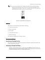
Modular type connectors
You see the following caution label near the modular type connectors on the back panel of the
product.
Caution:
The product uses a modular type connector exclusively for the cash drawer. Never plug a
telephone line into this connector.
Rev. A
i
Introduction
The TM-T88 (RS-232 serial interface specification)1 and the T88P (parallel interface specification) are line printers that
can print on a paper roll. The printer has the following features:
Printing
❏ High speed printing approximately 16.5 lines/second (1/6 inch feed).
❏ Low-noise thermal printing.
❏ High reliability due to a stable mechanism.
Application Software
❏ Command protocol is based on the ESC/POS™ standard.
❏ Various layouts are possible by using page mode.
❏ Characters can be scaled up to 64 times as large as the standard size. Smoothing is also
possible.
❏ Bar code printing is possible by using a bar code command. Bar codes can be printed both in
the vertical direction (fence bar code) and in the horizontal direction (ladder bar code)2.
❏ Repeated operation and copy printing are possible by using macro definitions.
❏ Character font size (12 x 24 font or 9 x 24 font) can be selected using a command.
Printer Handling
❏ Easy paper roll setting.
❏ Equipped with an auto-cutter.
❏ Easy maintenance for tasks such as head cleaning.
❏ Four different print densities selectable by DIP switches.
❏ Built-in interface provides control capability for two drawers.
1RS-485
serial interface is a dealer option.
2Effective
ii
in page mode
Rev. A
Warnings, Cautions and Notes
WARNING:
Warnings must be followed carefully to avoid bodily injury.
CAUTION:
Cautions must be observed to avoid damage to your equipment.
Note:
Notes have important information and useful tips on the operation of your printer.
Rev. A
iii
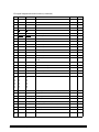
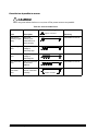
Revision Sheet
Revision
Page
Altered Item and Contents
Rev. A
iv
Rev. A
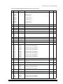
Contents
Chapter 1 Features and General Specifications
Printer Parts . . . . . . . . . . . . . . . . . . . . . . . . . . . . . . . . . . . . . . . . . . . . . . . . . . . . . . . . . . . . . . . . . . . . . . . . . . . . . . . . . . . . . . 1-1
Printing Specifications . . . . . . . . . . . . . . . . . . . . . . . . . . . . . . . . . . . . . . . . . . . . . . . . . . . . . . . . . . . . . . . . . . . . . . . . . 1-2
Character Specifications . . . . . . . . . . . . . . . . . . . . . . . . . . . . . . . . . . . . . . . . . . . . . . . . . . . . . . . . . . . . . . . . . . . . . . . . 1-3
Auto Cutter . . . . . . . . . . . . . . . . . . . . . . . . . . . . . . . . . . . . . . . . . . . . . . . . . . . . . . . . . . . . . . . . . . . . . . . . . . . . . . . . . . . 1-3
Paper Roll Supply Device . . . . . . . . . . . . . . . . . . . . . . . . . . . . . . . . . . . . . . . . . . . . . . . . . . . . . . . . . . . . . . . . . . . . . . . 1-4
Paper Specification . . . . . . . . . . . . . . . . . . . . . . . . . . . . . . . . . . . . . . . . . . . . . . . . . . . . . . . . . . . . . . . . . . . . . . . . . . . . . 1-4
Printable Area . . . . . . . . . . . . . . . . . . . . . . . . . . . . . . . . . . . . . . . . . . . . . . . . . . . . . . . . . . . . . . . . . . . . . . . . . . . . . . . . 1-5
Printing and Cutting Positions . . . . . . . . . . . . . . . . . . . . . . . . . . . . . . . . . . . . . . . . . . . . . . . . . . . . . . . . . . . . . . . . . . 1-6
Internal Buffer . . . . . . . . . . . . . . . . . . . . . . . . . . . . . . . . . . . . . . . . . . . . . . . . . . . . . . . . . . . . . . . . . . . . . . . . . . . . . . . . 1-6
Electrical Specifications . . . . . . . . . . . . . . . . . . . . . . . . . . . . . . . . . . . . . . . . . . . . . . . . . . . . . . . . . . . . . . . . . . . . . . . . . 1-6
EMI and Safety Standards Applied . . . . . . . . . . . . . . . . . . . . . . . . . . . . . . . . . . . . . . . . . . . . . . . . . . . . . . . . . . . . . . 1-7
Reliability . . . . . . . . . . . . . . . . . . . . . . . . . . . . . . . . . . . . . . . . . . . . . . . . . . . . . . . . . . . . . . . . . . . . . . . . . . . . . . . . . . . . 1-7
Environmental Conditions . . . . . . . . . . . . . . . . . . . . . . . . . . . . . . . . . . . . . . . . . . . . . . . . . . . . . . . . . . . . . . . . . . . . . . 1-8
Major Component Specifications . . . . . . . . . . . . . . . . . . . . . . . . . . . . . . . . . . . . . . . . . . . . . . . . . . . . . . . . . . . . . . . . . . . . . 1-9
M-T88 Printer Mechanism . . . . . . . . . . . . . . . . . . . . . . . . . . . . . . . . . . . . . . . . . . . . . . . . . . . . . . . . . . . . . . . . . . . . . . 1-9
Connectors . . . . . . . . . . . . . . . . . . . . . . . . . . . . . . . . . . . . . . . . . . . . . . . . . . . . . . . . . . . . . . . . . . . . . . . . . . . . . . . . . . . . . . . 1-9
Power Supply Connector . . . . . . . . . . . . . . . . . . . . . . . . . . . . . . . . . . . . . . . . . . . . . . . . . . . . . . . . . . . . . . . . . . . . . . . 1-10
Drawer Kick-out Connector (Modular Connector) . . . . . . . . . . . . . . . . . . . . . . . . . . . . . . . . . . . . . . . . . . . . . . . . . 1-10
Interface . . . . . . . . . . . . . . . . . . . . . . . . . . . . . . . . . . . . . . . . . . . . . . . . . . . . . . . . . . . . . . . . . . . . . . . . . . . . . . . . . . . . . . . . . . 1-12
RS-232 serial interface . . . . . . . . . . . . . . . . . . . . . . . . . . . . . . . . . . . . . . . . . . . . . . . . . . . . . . . . . . . . . . . . . . . . . . . . . . 1-13
Notes on setting DIP switch 2-1 to ON . . . . . . . . . . . . . . . . . . . . . . . . . . . . . . . . . . . . . . . . . . . . . . . . . . . . . . . . . . . 1-17
Notes on Resetting the Printer Using the Interface . . . . . . . . . . . . . . . . . . . . . . . . . . . . . . . . . . . . . . . . . . . . . . . . . 1-17
Buttons and Switches . . . . . . . . . . . . . . . . . . . . . . . . . . . . . . . . . . . . . . . . . . . . . . . . . . . . . . . . . . . . . . . . . . . . . . . . . . . . . . 1-18
Power Switch . . . . . . . . . . . . . . . . . . . . . . . . . . . . . . . . . . . . . . . . . . . . . . . . . . . . . . . . . . . . . . . . . . . . . . . . . . . . . . . . . 1-18
Panel Button . . . . . . . . . . . . . . . . . . . . . . . . . . . . . . . . . . . . . . . . . . . . . . . . . . . . . . . . . . . . . . . . . . . . . . . . . . . . . . . . . . 1-19
DIP Switches . . . . . . . . . . . . . . . . . . . . . . . . . . . . . . . . . . . . . . . . . . . . . . . . . . . . . . . . . . . . . . . . . . . . . . . . . . . . . . . . . . 1-19
Panel LEDs . . . . . . . . . . . . . . . . . . . . . . . . . . . . . . . . . . . . . . . . . . . . . . . . . . . . . . . . . . . . . . . . . . . . . . . . . . . . . . . . . . . 1-22
Self-test . . . . . . . . . . . . . . . . . . . . . . . . . . . . . . . . . . . . . . . . . . . . . . . . . . . . . . . . . . . . . . . . . . . . . . . . . . . . . . . . . . . . . . . . . . 1-23
Hexadecimal Dump . . . . . . . . . . . . . . . . . . . . . . . . . . . . . . . . . . . . . . . . . . . . . . . . . . . . . . . . . . . . . . . . . . . . . . . . . . . . . . . 1-23
Hexadecimal Dumping Function . . . . . . . . . . . . . . . . . . . . . . . . . . . . . . . . . . . . . . . . . . . . . . . . . . . . . . . . . . . . . . . . 1-23
Performing a Hexadecimal Dump . . . . . . . . . . . . . . . . . . . . . . . . . . . . . . . . . . . . . . . . . . . . . . . . . . . . . . . . . . . . . . . 1-23
Paper Sensors . . . . . . . . . . . . . . . . . . . . . . . . . . . . . . . . . . . . . . . . . . . . . . . . . . . . . . . . . . . . . . . . . . . . . . . . . . . . . . . . . . . . . 1-24
Cover Open Button . . . . . . . . . . . . . . . . . . . . . . . . . . . . . . . . . . . . . . . . . . . . . . . . . . . . . . . . . . . . . . . . . . . . . . . . . . . . 1-25
Cover Open Sensor . . . . . . . . . . . . . . . . . . . . . . . . . . . . . . . . . . . . . . . . . . . . . . . . . . . . . . . . . . . . . . . . . . . . . . . . . . . . 1-25
Print Buffer-full Printing . . . . . . . . . . . . . . . . . . . . . . . . . . . . . . . . . . . . . . . . . . . . . . . . . . . . . . . . . . . . . . . . . . . . . . . 1-25
Standard Accessories . . . . . . . . . . . . . . . . . . . . . . . . . . . . . . . . . . . . . . . . . . . . . . . . . . . . . . . . . . . . . . . . . . . . . . . . . . . . . . 1-25
Options . . . . . . . . . . . . . . . . . . . . . . . . . . . . . . . . . . . . . . . . . . . . . . . . . . . . . . . . . . . . . . . . . . . . . . . . . . . . . . . . . . . . . . . . . . 1-25
Consumables . . . . . . . . . . . . . . . . . . . . . . . . . . . . . . . . . . . . . . . . . . . . . . . . . . . . . . . . . . . . . . . . . . . . . . . . . . . . . . . . . . . . . 1-26
Specified thermal roll paper: NTP080-80 . . . . . . . . . . . . . . . . . . . . . . . . . . . . . . . . . . . . . . . . . . . . . . . . . . . . . . . . . . 1-26
External Power Supply PS-170 Specifications . . . . . . . . . . . . . . . . . . . . . . . . . . . . . . . . . . . . . . . . . . . . . . . . . . . . . . . . . . 1-27
Rev. A
v
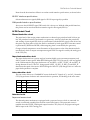
Chapter 2 Mechanisms and Operation
Component Connection Diagram . . . . . . . . . . . . . . . . . . . . . . . . . . . . . . . . . . . . . . . . . . . . . . . . . . . . . . . . . . . . . . . . . . .
Circuit Block Diagram . . . . . . . . . . . . . . . . . . . . . . . . . . . . . . . . . . . . . . . . . . . . . . . . . . . . . . . . . . . . . . . . . . . . . . . . . . . . .
Memory Map . . . . . . . . . . . . . . . . . . . . . . . . . . . . . . . . . . . . . . . . . . . . . . . . . . . . . . . . . . . . . . . . . . . . . . . . . . . . . . . . . . . .
M-T88 Printer Mechanism . . . . . . . . . . . . . . . . . . . . . . . . . . . . . . . . . . . . . . . . . . . . . . . . . . . . . . . . . . . . . . . . . . . . . . . . .
Paper Feed Mechanism . . . . . . . . . . . . . . . . . . . . . . . . . . . . . . . . . . . . . . . . . . . . . . . . . . . . . . . . . . . . . . . . . . . . . . . .
Paper Supply Mechanism . . . . . . . . . . . . . . . . . . . . . . . . . . . . . . . . . . . . . . . . . . . . . . . . . . . . . . . . . . . . . . . . . . . . . .
Printer Mechanism . . . . . . . . . . . . . . . . . . . . . . . . . . . . . . . . . . . . . . . . . . . . . . . . . . . . . . . . . . . . . . . . . . . . . . . . . . . .
Cutter Mechanism . . . . . . . . . . . . . . . . . . . . . . . . . . . . . . . . . . . . . . . . . . . . . . . . . . . . . . . . . . . . . . . . . . . . . . . . . . . .
Cover Mechanism . . . . . . . . . . . . . . . . . . . . . . . . . . . . . . . . . . . . . . . . . . . . . . . . . . . . . . . . . . . . . . . . . . . . . . . . . . . .
Display Mechanism . . . . . . . . . . . . . . . . . . . . . . . . . . . . . . . . . . . . . . . . . . . . . . . . . . . . . . . . . . . . . . . . . . . . . . . . . . .
Main Circuit Board Unit-A . . . . . . . . . . . . . . . . . . . . . . . . . . . . . . . . . . . . . . . . . . . . . . . . . . . . . . . . . . . . . . . . . . . . . . . . .
CPU and CPU Peripheral Logic Circuits . . . . . . . . . . . . . . . . . . . . . . . . . . . . . . . . . . . . . . . . . . . . . . . . . . . . . . . . .
M-T88 Control Circuit . . . . . . . . . . . . . . . . . . . . . . . . . . . . . . . . . . . . . . . . . . . . . . . . . . . . . . . . . . . . . . . . . . . . . . . . .
Control Panel Control Circuit . . . . . . . . . . . . . . . . . . . . . . . . . . . . . . . . . . . . . . . . . . . . . . . . . . . . . . . . . . . . . . . . . . .
DIP Switch Read Circuit . . . . . . . . . . . . . . . . . . . . . . . . . . . . . . . . . . . . . . . . . . . . . . . . . . . . . . . . . . . . . . . . . . . . . . .
Malfunction Protection Circuit . . . . . . . . . . . . . . . . . . . . . . . . . . . . . . . . . . . . . . . . . . . . . . . . . . . . . . . . . . . . . . . . . .
Drawer Kick Control Circuit . . . . . . . . . . . . . . . . . . . . . . . . . . . . . . . . . . . . . . . . . . . . . . . . . . . . . . . . . . . . . . . . . . .
Power Supply Circuit . . . . . . . . . . . . . . . . . . . . . . . . . . . . . . . . . . . . . . . . . . . . . . . . . . . . . . . . . . . . . . . . . . . . . . . . .
I/F Circuit Board Assembly . . . . . . . . . . . . . . . . . . . . . . . . . . . . . . . . . . . . . . . . . . . . . . . . . . . . . . . . . . . . . . . . . . . . . . . .
I/F Circuit Board Assembly Types . . . . . . . . . . . . . . . . . . . . . . . . . . . . . . . . . . . . . . . . . . . . . . . . . . . . . . . . . . . . . .
Interface Board Structure . . . . . . . . . . . . . . . . . . . . . . . . . . . . . . . . . . . . . . . . . . . . . . . . . . . . . . . . . . . . . . . . . . . . . .
Switchboard B . . . . . . . . . . . . . . . . . . . . . . . . . . . . . . . . . . . . . . . . . . . . . . . . . . . . . . . . . . . . . . . . . . . . . . . . . . . . . . . . . . . .
2-1
2-2
2-3
2-4
2-4
2-8
2-10
2-12
2-15
2-17
2-18
2-19
2-25
2-26
2-26
2-26
2-26
2-27
2-28
2-28
2-28
2-28
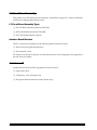
Chapter 3 Handling, Maintenance, and Repairs
Handling . . . . . . . . . . . . . . . . . . . . . . . . . . . . . . . . . . . . . . . . . . . . . . . . . . . . . . . . . . . . . . . . . . . . . . . . . . . . . . . . . . . . . . . .
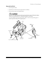
Transport Precautions . . . . . . . . . . . . . . . . . . . . . . . . . . . . . . . . . . . . . . . . . . . . . . . . . . . . . . . . . . . . . . . . . . . . . . . . .
Setup Precautions . . . . . . . . . . . . . . . . . . . . . . . . . . . . . . . . . . . . . . . . . . . . . . . . . . . . . . . . . . . . . . . . . . . . . . . . . . . . .
Operational Precautions . . . . . . . . . . . . . . . . . . . . . . . . . . . . . . . . . . . . . . . . . . . . . . . . . . . . . . . . . . . . . . . . . . . . . . .
Paper Precautions . . . . . . . . . . . . . . . . . . . . . . . . . . . . . . . . . . . . . . . . . . . . . . . . . . . . . . . . . . . . . . . . . . . . . . . . . . . . .
About the mounting position of the paper near end sensor . . . . . . . . . . . . . . . . . . . . . . . . . . . . . . . . . . . . . . . . .
Problem Solving . . . . . . . . . . . . . . . . . . . . . . . . . . . . . . . . . . . . . . . . . . . . . . . . . . . . . . . . . . . . . . . . . . . . . . . . . . . . . . . . . .
Errors . . . . . . . . . . . . . . . . . . . . . . . . . . . . . . . . . . . . . . . . . . . . . . . . . . . . . . . . . . . . . . . . . . . . . . . . . . . . . . . . . . . . . . .
Clearing Paper Jams . . . . . . . . . . . . . . . . . . . . . . . . . . . . . . . . . . . . . . . . . . . . . . . . . . . . . . . . . . . . . . . . . . . . . . . . . . . . . . .
Inspection and Maintenance . . . . . . . . . . . . . . . . . . . . . . . . . . . . . . . . . . . . . . . . . . . . . . . . . . . . . . . . . . . . . . . . . . . . . . . .
Maintenance Procedures . . . . . . . . . . . . . . . . . . . . . . . . . . . . . . . . . . . . . . . . . . . . . . . . . . . . . . . . . . . . . . . . . . . . . . .
Cleaning . . . . . . . . . . . . . . . . . . . . . . . . . . . . . . . . . . . . . . . . . . . . . . . . . . . . . . . . . . . . . . . . . . . . . . . . . . . . . . . . . . . . .
Lubricants . . . . . . . . . . . . . . . . . . . . . . . . . . . . . . . . . . . . . . . . . . . . . . . . . . . . . . . . . . . . . . . . . . . . . . . . . . . . . . . . . . . . . . .
Lubrication Standard . . . . . . . . . . . . . . . . . . . . . . . . . . . . . . . . . . . . . . . . . . . . . . . . . . . . . . . . . . . . . . . . . . . . . . . . . .
Type of Lubricants . . . . . . . . . . . . . . . . . . . . . . . . . . . . . . . . . . . . . . . . . . . . . . . . . . . . . . . . . . . . . . . . . . . . . . . . . . . .
3-1
3-1
3-1
3-1
3-2
3-5
3-7
3-7
3-8
3-8
3-9
3-10
3-11
3-11
3-11
Chapter 4 Troubleshooting Guide
Self-test . . . . . . . . . . . . . . . . . . . . . . . . . . . . . . . . . . . . . . . . . . . . . . . . . . . . . . . . . . . . . . . . . . . . . . . . . . . . . . . . . . . . . . . . . .
Performing the Self-test . . . . . . . . . . . . . . . . . . . . . . . . . . . . . . . . . . . . . . . . . . . . . . . . . . . . . . . . . . . . . . . . . . . . . . . .
Self-test End . . . . . . . . . . . . . . . . . . . . . . . . . . . . . . . . . . . . . . . . . . . . . . . . . . . . . . . . . . . . . . . . . . . . . . . . . . . . . . . . . .
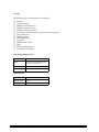
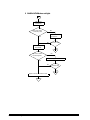
Troubleshooting Flowcharts . . . . . . . . . . . . . . . . . . . . . . . . . . . . . . . . . . . . . . . . . . . . . . . . . . . . . . . . . . . . . . . . . . . . . . . .
Error Types and Processing . . . . . . . . . . . . . . . . . . . . . . . . . . . . . . . . . . . . . . . . . . . . . . . . . . . . . . . . . . . . . . . . . . . . . . . .
Error types . . . . . . . . . . . . . . . . . . . . . . . . . . . . . . . . . . . . . . . . . . . . . . . . . . . . . . . . . . . . . . . . . . . . . . . . . . . . . . . . . . .
4-1
4-1
4-1
4-2
4-9
4-9
vi
Rev. A
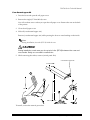
Chapter 5 Disassembly, Assembly, and Adjustment
Before starting disassembly, assembly, and adjustment . . . . . . . . . . . . . . . . . . . . . . . . . . . . . . . . . . . . . . . . . . . . . 5-1
Small Parts . . . . . . . . . . . . . . . . . . . . . . . . . . . . . . . . . . . . . . . . . . . . . . . . . . . . . . . . . . . . . . . . . . . . . . . . . . . . . . . . . . . . . . . 5-1
Using This Manual . . . . . . . . . . . . . . . . . . . . . . . . . . . . . . . . . . . . . . . . . . . . . . . . . . . . . . . . . . . . . . . . . . . . . . . . . . . . . . . . 5-2
Titles . . . . . . . . . . . . . . . . . . . . . . . . . . . . . . . . . . . . . . . . . . . . . . . . . . . . . . . . . . . . . . . . . . . . . . . . . . . . . . . . . . . . . . . . 5-2
Disassembly, Assembly, and Adjustment Procedures . . . . . . . . . . . . . . . . . . . . . . . . . . . . . . . . . . . . . . . . . . . . . . 5-2
Names of Parts and Blocks . . . . . . . . . . . . . . . . . . . . . . . . . . . . . . . . . . . . . . . . . . . . . . . . . . . . . . . . . . . . . . . . . . . . . . 5-2
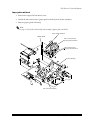
TM-T88 Series Disassembly, Assembly, and Adjustment . . . . . . . . . . . . . . . . . . . . . . . . . . . . . . . . . . . . . . . . . . . . . . . . 5-3
Level 1 Disassembly and Assembly . . . . . . . . . . . . . . . . . . . . . . . . . . . . . . . . . . . . . . . . . . . . . . . . . . . . . . . . . . . . . . 5-3
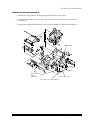
Level 3 Disassembly and Assembly . . . . . . . . . . . . . . . . . . . . . . . . . . . . . . . . . . . . . . . . . . . . . . . . . . . . . . . . . . . . . . 5-12
M-T88 Printer Mechanism Disassembly and Assembly . . . . . . . . . . . . . . . . . . . . . . . . . . . . . . . . . . . . . . . . . . . . . . . . . 5-14
Level 1 Disassembly and Assembly . . . . . . . . . . . . . . . . . . . . . . . . . . . . . . . . . . . . . . . . . . . . . . . . . . . . . . . . . . . . . . 5-14
Level 2 Disassembly and Assembly . . . . . . . . . . . . . . . . . . . . . . . . . . . . . . . . . . . . . . . . . . . . . . . . . . . . . . . . . . . . . . 5-29
Appendix
IEEE 1284 Parallel Interface . . . . . . . . . . . . . . . . . . . . . . . . . . . . . . . . . . . . . . . . . . . . . . . . . . . . . . . . . . . . . . . . . . . . . . . . . A-1
RS-485 Serial Interface . . . . . . . . . . . . . . . . . . . . . . . . . . . . . . . . . . . . . . . . . . . . . . . . . . . . . . . . . . . . . . . . . . . . . . . . . . . . . . A-5
XON/XOFF Transmit Timing . . . . . . . . . . . . . . . . . . . . . . . . . . . . . . . . . . . . . . . . . . . . . . . . . . . . . . . . . . . . . . . . . . . A-9
Data Format When Using RS-485 . . . . . . . . . . . . . . . . . . . . . . . . . . . . . . . . . . . . . . . . . . . . . . . . . . . . . . . . . . . . . . . . A-9
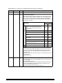
Main Circuit Board Unit-A Parts Layout (parts side) Part No. 202254500 . . . . . . . . . . . . . . . . . . . . . . . . . . . . . . . . . . A-11
Main Circuit Board Unit-A Parts Layout (solder side) Part No. 202254500 . . . . . . . . . . . . . . . . . . . . . . . . . . . . . . . . . A-12
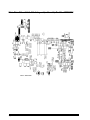
Main Circuit Board Unit-A Parts Layout (parts side) Part No. 202254501 . . . . . . . . . . . . . . . . . . . . . . . . . . . . . . . . . . A-13
Main Circuit Board Unit-A Parts Layout (solder side) Part No. 202254501 . . . . . . . . . . . . . . . . . . . . . . . . . . . . . . . . . A-14
RS-232 Serial Interface Circuit Board Parts Layout . . . . . . . . . . . . . . . . . . . . . . . . . . . . . . . . . . . . . . . . . . . . . . . . . . . . . A-15
IEEE 1284 Parallel Interface Circuit Board Parts Layout . . . . . . . . . . . . . . . . . . . . . . . . . . . . . . . . . . . . . . . . . . . . . . . . . A-16
RS-485 Serial Interface Circuit Board Parts Layout . . . . . . . . . . . . . . . . . . . . . . . . . . . . . . . . . . . . . . . . . . . . . . . . . . . . . A-17
Switch Circuit Board Assembly-B . . . . . . . . . . . . . . . . . . . . . . . . . . . . . . . . . . . . . . . . . . . . . . . . . . . . . . . . . . . . . . . . . . . . A-17
Case Unit Parts Name List . . . . . . . . . . . . . . . . . . . . . . . . . . . . . . . . . . . . . . . . . . . . . . . . . . . . . . . . . . . . . . . . . . . . . . . . . . A-18
M-T88 Printer Mechanism Parts Name List . . . . . . . . . . . . . . . . . . . . . . . . . . . . . . . . . . . . . . . . . . . . . . . . . . . . . . . . . . . A-19
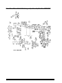
Overall Exploded Diagram . . . . . . . . . . . . . . . . . . . . . . . . . . . . . . . . . . . . . . . . . . . . . . . . . . . . . . . . . . . . . . . . . . . . . . . . . . A-21
Case Unit . . . . . . . . . . . . . . . . . . . . . . . . . . . . . . . . . . . . . . . . . . . . . . . . . . . . . . . . . . . . . . . . . . . . . . . . . . . . . . . . . . . . . . . A-21
M-T88 Printer Mechanism. . . . . . . . . . . . . . . . . . . . . . . . . . . . . . . . . . . . . . . . . . . . . . . . . . . . . . . . . . . . . . . . . . . . . . . . . A-22
Lubrication Points Diagram . . . . . . . . . . . . . . . . . . . . . . . . . . . . . . . . . . . . . . . . . . . . . . . . . . . . . . . . . . . . . . . . . . . . . . . . . A-23
M-T88 Printer Mechanism. . . . . . . . . . . . . . . . . . . . . . . . . . . . . . . . . . . . . . . . . . . . . . . . . . . . . . . . . . . . . . . . . . . . . . . . . A-23
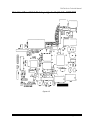
Circuit Board Diagram. . . . . . . . . . . . . . . . . . . . . . . . . . . . . . . . . . . . . . . . . . . . . . . . . . . . . . . . . . . . . . . . . . . . . . . . . . . . . . A-24
Main Circuit Board Unit-A . . . . . . . . . . . . . . . . . . . . . . . . . . . . . . . . . . . . . . . . . . . . . . . . . . . . . . . . . . . . . . . . . . . . . . . . A-24
RS-232 Interface Board. . . . . . . . . . . . . . . . . . . . . . . . . . . . . . . . . . . . . . . . . . . . . . . . . . . . . . . . . . . . . . . . . . . . . . . . . . . . . . A-25
IEEE 1284 Interface . . . . . . . . . . . . . . . . . . . . . . . . . . . . . . . . . . . . . . . . . . . . . . . . . . . . . . . . . . . . . . . . . . . . . . . . . . . . . . . . A-26
RS-485 Interface Board . . . . . . . . . . . . . . . . . . . . . . . . . . . . . . . . . . . . . . . . . . . . . . . . . . . . . . . . . . . . . . . . . . . . . . . . . . . . . A-27
Switch Circuit Board Assembly-B . . . . . . . . . . . . . . . . . . . . . . . . . . . . . . . . . . . . . . . . . . . . . . . . . . . . . . . . . . . . . . . . . . . . A-28
Rev. A
vii
viii
Rev. A
TM-T88 Series Technical Manual
Chapter 1
Features and General Specifications
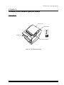
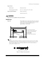
Printer Parts
Printer cover
Control panel
POWER
PO
WE
ER
R
RO
R
P
OU APE
R
T
FE
ED
ERROR
PAPER
OUT
FEED
Cutter cover
Cover open button
Figure 1-1 TM-T88 appearance
Rev. A
Features and General Specifications 1-1
Printing Specifications
Printing method:
Thermal line printing
Dot density:
180 dpi × 180 dpi. The number of dots per 25.4 mm (1")
Printing direction:
Unidirectional with friction feed
Printing width:
72 mm (2.83"), 512 dot positions
Characters per line:
42 (font A)
56 (font B)
0.28 mm (.01") (2 dots) (font A)
Character spacing:
0.28 mm (.01") (2 dots) (font B)
Programmable by control command.
Printing speed:
High speed:
Approximately 16.5 lines/second (1/6 inch feed)
(at 24V, 20°C, Density level 2)
Approximately 2.76 inches/second (approximately
70 mm/second)
Low speed:
Approximately 11.8 lines/second (1/6 inch feed)
Approximately 2.0 inches/second (approximately
50 mm/second)
High and Low speeds are switched automatically
depending on the voltage applied to the printer and the
environment temperature.
Approximately 1.1 inches/second (approximately
28 mm/second) when a ladder bar code is printed.
Notes:
Printing speed may be slower depending on the data transmission speed and the
combination of control commands.
The printer switches the mode of the printing speed automatically.
There may be variations in printing after switching the mode of the printing speed.
To prevent this for logo printing, using a downloaded bit image is recommended.
1-2 Features and General Specifications
Rev. A
TM-T88 Series Technical Manual
Paper feed speed:
Approximately 2.76 inches/second (approximately
70 mm/second) (continuous printing)
Line spacing:
1/6 inch (4.23 mm)
Programmable by control command
Character Specifications
Number of characters:
Alphanumeric characters:
95
Extended graphics:
128 × 7 pages (including one space page)
International characters:
32
12 × 24 (font A) (including 2-dot spacing in horizontal)
Character structure:
9 × 24 (font B) (including 2-dot spacing in horizontal)
Font A is selected as the default
Character size:
Standard
Double-height
Double-width/
Double-height
Double-width
W × H (mm)
CPL
W × H (mm)
CPL
W × H (mm)
CPL
W × H (mm)
CPL
Font A
12 × 24
1.41 × 3.39
(.06" × .13")
42
1.41 × 6.77
(.06" × .27")
42
2.82 × 3.39
(.11" × .13")
21
2.82 × 6.77
(.11" × .27")
21
Font B
9 × 24
0.99 × 3.39
(.04" × .13")
56
0.99 × 6.77
(.04" × .27")
56
1.98 × 3.39
(.08" × .13")
28
1.98 × 6.77
(.08" × .27")
28
Space between characters is not included.
Characters can be scaled up to 64 times as large as the standard sizes.
CPL = Characters per line
Auto Cutter
Partial cut:
Cutting with one point left uncut (selectable by GS V)
Note:
To prevent dot displacement, after cutting, paper must be fed approximately 1 mm (14/360
inches) or more before printing.
Rev. A
Features and General Specifications 1-3
Paper Roll Supply Device
Supply method:
Drop-in paper roll
Near-end sensor
Detection method:
Microswitch
Paper roll spool diameter:
Inside: 12 mm (.47")
Outside: 18 mm (.71")
Near-end adjustment:
Adjusting screw
Remaining amount:
Fixed position #1 (approximately 23 mm (0.9”))
#2 (approximately 27 mm (1.06”)
(The adjusting screw has two positions.)
Note:
You can use a command to stop printing upon detection of a paper near-end.
Paper Specification
Paper type:
Specified thermal roll paper, NTP080-80
In Japan: Nakagawa, Seisakujo
In U.S.A.: Nakagawa Mfg. (USA) Inc.
In Europe: Nakagawa Mfg. (Europe) GmbH
In Southeast Asia: N.A.K. Mfg. (Malaysia) SDN BHD
Original paper: TF50KS E Nippon Paper Industries
Co.,Ltd.
The following paper can be used instead of the specified
paper above:
Original paper: PD 160R New Oji Paper Mfg. Co. Ltd.
Original paper: AF50KS-E Jujo Thermal Oy (Finland)
Original paper: F380 Kanzaki Specialty Papers, Inc.
(U.S.A.)
Form:
Paper roll
Paper width:
79.5 ±0.5 mm (3.13" ± 0.02")
1-4 Features and General Specifications
Rev. A
TM-T88 Series Technical Manual
Paper roll size:
Roll diameter:
Maximum 83 mm
Take-up paper roll width:
80 + 0.5/-1.0 mm (3.15" + 0.02"/-0.04")
Inside: 12 mm (.47")
Paper roll spool diameter:
Outside: 18 mm (.71")
CAUTION
Paper must not be pasted to the paper roll spool.
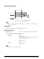
Printable Area
The printable area of a paper with width of 79.5 ± 0.5 mm
(3.13" ± 0.02") is 72.2 ± 0.2 mm (2.84" ± 0.008") (512 dots)
and the space on the right and left sides are
approximately 3.7 mm (0.146").
Paper roll
a
b
a = 79.5 ± 0.5 mm (3.13" ± 0.02")
b = 0.141 mm ± 0.05 mm (.006" ± .002")
c = 72.2 mm ± 0.2 mm (2.84 ± .008")
d = 3.7 mm (0.146”)
e = 3.7 mm (0.146”)
[All the numeric values are typical.]
c
d
e
Figure 1-2 Printable area
Note:
The print position within the printable area of the thermal elements for dots 257 to 512 is shifted
approximately 0.07 mm (.003") in the paper feed direction from the position for dots 1 to 256. Be
sure not to print a ladder bar code across both printable areas, as this can cause variations in
printing which are difficult to read.
1
256
257
512
Approximately 0.07 mm (0.0028")
Approximately 0.07mm (0.0028")
Figure 1-3 Shifting of the print position
Rev. A
Features and General Specifications 1-5
Printing and Cutting Positions
Emergency-cutter
Manual-cutterposition
position
Approx.
26
26.3
Approx.14.8
15
Auto-cutter blade position
Paper feed direction
Center of the print dotline
[ Units: mm (All the numeric values are typical.) ]
Figure 1-4 Printing and cutting positions
Note:
Numeric values used here are typical values; the values may vary slightly as a result of paper slack
or variations in the paper.
Internal Buffer
Receive buffer selectable as 45 or 4K bytes using the DIP switch.
Electrical Specifications
Supply voltage:
+24 VDC ± 7% (optional power supply: EPSON PS-170)
Current consumption (at 24V, normal temperature)
Operating:
Mean:
Approximately 1.5A
(Character font A α-N, capital letters, 36-character rolling
pattern, 42 column printing)
Peak:
Approximately 5.0A
Standby:
Mean:
Approximately 0.2A
Note:
Maximum 1A for drawer kick-out driving.
1-6 Features and General Specifications
Rev. A
TM-T88 Series Technical Manual
EMI and Safety Standards Applied
(EMC is tested using the EPSON PS-170 power supply)
Europe:
North America:
Japan:
CE marking:
EN55022
EN50082-1
EN45501
Safety Standard:
TÜV (EN60950)
EMI:
FCC Class A
Safety standards:
UL1950-2TH-D3
C-UL
EMI:
VCCI Class 1
Conditions of acceptability
1. This component has been judged on the basis of the required spacing in the Standard for
Information Technology Equipment, including Electrical Business Equipment, UL 1950
and CSA22.2 No. 950. sub-clause 2.9, which would cover the component itself if
submitted for Listing.
2. This unit is intended to be supplied by a SELV circuit only.
3. The terminals and connectors have not been evaluated for field wiring.
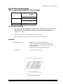
Reliability
MCBF: Mechanism:
10,000,000 lines (Life: 15,000,000 lines)
(when printing with font A; Print density level 2)
(when performing autocutting once each for every
10 lines printed)
(Based on the test patterns shown below.)
Print head life:
100 million pulses, 100 km
Figure 1-5 Printing pattern
Rev. A
Features and General Specifications 1-7
Acoustic noise:
Operating:
Approximately 55 dB
(Bystander position)
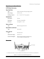
External Dimensions and Weight
Height:
Approximately 148 mm (5.83")
Width:
Approximately 145 mm (5.71")
Depth:
Approximately 195 mm (7.68")
Weight:
Approximately1.8 kg (3.96 lbs)
(excpet for the paper roll)
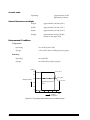
Environmental Conditions
Temperature:
Operating:
5° to 45°C (41° to 113°F)
Storage:
–10° to 50°C (14° to 122°F) (except for paper)
Humidity:
Operating:
10 to 90% RH
Storage:
10 to 90% RH (except for paper)
[% RH]
90
34 ˚C, 90 %
80
40 ˚C, 65 %
60
Relative humidity
45 ˚C, 50 %
Operating environment
range
40
20
10
0
0
10
20
30
40
Ambient
temperature
50
[˚C]
Figure 1-6 Operating temperature and humidity range
1-8 Features and General Specifications
Rev. A
TM-T88 Series Technical Manual
Major Component Specifications
M-T88 Printer Mechanism
Paper Feed Motor
Type:
4-phase, 48-polarity, PM type stepping motor
Drive Voltage:
24 V DC ± 10%
Winding resistance:
90 Ω ± 7% at 25° C (77° F), per phase
Print Head Unit
Dot number:
512 dots
Dot density:
0.141 mm/dot (180 DPI)
Resistance:
Average 865 Ω ± 4.6%
Paper-end Sensor
Reflection type photo sensor
Type:
Paper Roll Near-end Sensor
Microswitch
Type:
Auto-cutter Unit
Type:
DC brush motor
Cutter motor voltage:
24 V DC ± 7%
Current consumption:
700 mA peak (at starting, low temperature)
70 mA average (room temperature)
Connectors
Power supply
FG
FG
Interface
DK
DC24V
Drawer kick-out
Grounding screw
(*) The shape of the interface connector is different from the illustration above if the printer has a parallel interface.
Figure 1-7 Connector panel external appearance
Rev. A
Features and General Specifications 1-9
Power Supply Connector
This connector is used to connect the printer to an external power source.
Printer Side:
Hosiden TCS7960-532010 or equivalent
User side:
Hosiden TCP8927-631100 or equivalent
Hosiden TCP8927-531100 or equivalent
Pin number
Signal name
1
+24 VDC
2
GND
3
NC
Shell
Frame GND
2
3 1
Shell
Figure 1-8 Power supply connector
Note:
Be sure to connect the ground wire to the printer using the FG screw on the bottom of the printer.
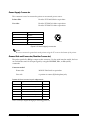
Drawer Kick-out Connector (Modular Connector)
The pulse specified by ESC p is output to this connector. For the serial interface model, the host
can confirm the status of the input signal by using the DLE EOT, GS r, or GS a (ASB)
commands.
Connector model:
Printer side:
MOLEX 52065-6615 or equivalent
User side:
6-position 6-contact (RJ12 telephone jack)
Drawer kick-out connector pin assignments
Pin Number
Signal Name
Direction
1
Frame GND
—
2
Drawer Kick-out drive signal 1
Output
3
Drawer open/close signal
Input
4
+24 V
—
5
Drawer Kick-out drive signal 2
Output
6
Signal GND
—
+24 V is always output through pin 4 during power on.
1-10 Features and General Specifications
Rev. A
TM-T88 Series Technical Manual
CAUTION
Pin 4 must be used only for the drawer.
1
6
Figure 1-9 Drawer kick-out connector
Drawer kick-out drive signal
Output signal:
Output voltage: Approximately 24 V
Output current: 1A or less
CAUTION:
To avoid an overcurrent, the resistance of the drawer kick-out solenoid must be
24 Ω or more.
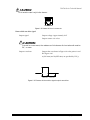
Output waveform:
Outputs the waveforms in Figure 1-9 to the points A and
B in Figure 1-10.
t1 (ON time) and t2 (OFF time) are specified by ESC p.
t 1x2
m sec t 2x2 m sec
t 1x
2 msec
t 1x 2 msec
Figure 1-10 Drawer kick-out drive signal output waveform
Rev. A
Features and General Specifications 1-11
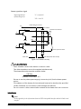
Drawer open/close signal
Input signal level
(connector pin 3):
"L" = 0 to 0.8 V
"H" = 2 to 5 V
Drawer kick-out connector
1
F. G
With shielded
Drawer kick-out solenoid
2
A
3
P-GND
+24V
4
5
B
Drawer open/close switch
6
P-GND
Printer side
User side (Drawer kick-out side)
Figure 1-11 Drawer circuitry
CAUTIONS:
Use a shielded cable for the drawer connector cable.
Two driver transistors cannot be energized simultaneously.
The drawer drive duty must be as shown below.
ON Time
(ON time + OFF time) ≤ 0.2
Be sure to use the printer power supply (connector pin 4) for the drawer power
source.
The resistance of the drawer kick-out solenoid must not be less than the specified
(24 W). Otherwise, an overcurrent could damage the solenoid.
Do not connect a telecommunication network to the drawer kick-out connector.
Interface
Note:
See the appendix for the information about the IEEE 1284 parallel interface and the RS-485 serial
interface.
1-12 Features and General Specifications
Rev. A
TM-T88 Series Technical Manual
RS-232 serial interface
Specifications
Data transmission:
Serial
Synchronization:
Asynchronous
Handshaking:
DTR/DSR or XON/XOFF control
Signal levels:
MARK = –3 to –15 V: Logic "1"/OFF
SPACE = +3 to +15 V: Logic "0"/ON
Baud rate:
2400, 4800, 9600, 19200 bps
Data word length:
7 or 8 bits
Parity:
None, even, odd
Stop bits:
1 or more
Connector (printer side):
Female DSUB-25 pin connector
Notes:
The handshaking, data word length, baud rate, and parity depend on the DIP switch settings.
Data transmitted from the printer has 1 stop bit (fixed).
Switching between on-line and off-line
The printer does not have an on-line/off-line switch. The
printer goes off-line:
❏ Between when the power is turned on (including
reset using the interface) and when the printer is
ready to receive data
❏ During the self-test
❏ When the cover is open
❏ During paper feeding using the paper feed switch
❏ When the printer stops printing due to a paper-end
(in cases when an empty paper supply is detected by
either paper roll end detector or the paper roll nearend detector with a printing halt feature using
ESC c 4)
❏ During macro executing standby status.
❏ When a temporary abnormality ocurrs in the power
supply voltage.
❏ When an error has occurred
Rev. A
Features and General Specifications 1-13
Interface connector terminal assignments and signal functions are described in the table
below.
TM-T88 series printer status and signals (continued)
Pin number
Signal name
Signal direction
Function
1
FG
—
Frame ground
2
TXD
Output
Transmit data
3
RXD
Input
Receive data
4
RTS
Output
Same as DTR signal (Pin 20)
6
DSR
Input
This signal indicates whether the host computer can receive data.
SPACE indicates that the host computer can receive data, and
MARK indicates that the host computer cannot receive data.
When DTR/DSR control is selected, the printer transmits data after
confirming this signal (except when transmitting data by DLE EOT,
and GS a).
When XON/XOFF control is selected, the printer does not check this
signal.
Changing the DIP switch setting enables this signal to be used as a
reset signal for the printer.
The printer is reset when the signal remains MARK for 1 ms or more.
7
SG
—
1-14 Features and General Specifications
Signal ground
Rev. A
TM-T88 Series Technical Manual
TM-T88 series printer status and signals (continued)
(continued)
Pin number
Signal name
Signal direction
Function
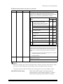
20
DTR
Output
1) When DTR/DSR control is selected, this signal indicates whether
the printer is busy. SPACE indicates that the printer is ready to
receive data, and MARK indicates that the printer is busy. The busy
condition can be changed by using DIP SW 2-1 as follows:
DIP SW 2-1 status
Off-line
Printer
ON
OFF
1. During the period from when the
power is turned on (including
resetting using the interface) to when
the printer is ready to receive data.
BUSY
BUSY
2. During the self-test.
BUSY
BUSY
3. When the cover is open.
-
BUSY
4. During paper feeding using the
paper feed switch.
-
BUSY
5. When the printer stops printing due to
a paper-end.
-
BUSY
6. During macro executing standby
status.
-
BUSY
7. When a temporary abnormality
ocurrs in the power supply voltage.
-
BUSY
8. When an error has occurred.
-
BUSY
9. When the receive buffer becomes
full.
BUSY
BUSY
2) When XON/XOFF control is selected:
The signal indicates whether the printer is correctly connected and
is ready to receive data. SPACE indicates that the printer is ready to
receive data. The signal is always SPACE except in the following
cases:
• During the period from when the power is turned on to when
the printer is ready to receive data
• During the self-test
25
INIT
Input
Changing the DIP switch setting enables this signal to be used as a
reset signal for the printer.
The printer is reset when the signal remains SPACE for 1 ms or more.
Notes:
When the remaining space in the receive buffer drops to 16 bytes, the printer status becomes "buffer
full" and it remains "buffer full" until the space in the receive buffer increases to 26 bytes.
The printer ignores the data received when the remaining space in the receive buffer is 0 bytes.
XON/XOFF transmit timing
Rev. A
When XON/XOFF control is selected, the printer
transmits XON or XOFF signals as follows. Transmit
timing differs depending on the DIP SW2-1 setting.
Features and General Specifications 1-15
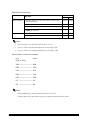
XON/XOFF transmit timing
DIP SW 1-3 status
Printer status
XON transmission
XOFF Transmission
ON
OFF
1) When the printer goes on-line after turning on the power (or
reset using interface)
Transmit
Transmit
2) When the receive buffer is released from the buffer full state
Transmit
Transmit
3) When the printer switches from off-line to on-line
—
Transmit
4) When the printer recovers from an error using the DLE ENQ 1 or
DLE ENQ 2 commands
—
Transmit
5) When the receive buffer becomes full
Transmit
Transmit
6) When the printer switches from on-line to off-line
—
Transmit
Notes:
•
The XON code is <11>H and the XOFF code is <13>H.
•
In case 3, XON is not transmitted when the receive buffer is full.
•
In case 6, XOFF is not transmitted when the receive buffer is full
Serial interface connection example.
Host
(DTE ex. 8251)
Printer
TXD –––––––––––––––– RXD
DSR –––––––––––––––– DTR
CTS –––––––––––––––– RTS
RXD –––––––––––––––– TXD
DTR –––––––––––––––– DSR
FG –––––––––––––––– FG
SG –––––––––––––––– SG
Notes:
Set the handshaking so that the transmit data can be received.
Transmit data to the printer after turning on the power and initializing the printer.
1-16 Features and General Specifications
Rev. A
TM-T88 Series Technical Manual
Notes on setting DIP switch 2-1 to ON
❏ The printer mechanism stops but does not become busy when: an error has occurred, the
cover is open, printing stops due to a paper-end, or paper is fed using the paper feed switch.
❏ When setting DIP switch 2-1 to ON to enable handshaking with the printer, be sure to check
the printer status using the GS a command and the ASB function. In this setting, the default
value of n for GS a is 2. The printer automatically transmits the printer status, depending on
on-line/off-line changes.
❏ When using DLE EOT and DLE ENQ, be sure that the receive buffer does not become full.
• When using a host that cannot transmit data when the printer is busy:
If an error has occurred, DLE EOT and DLE ENQ cannot be used when the printer is
busy due to a receive buffer-full state.
• When using a host that can transmit data when the printer is busy:
When the receive buffer becomes full while transmitting bit-image data, DLE EOT or
DLE ENQ used while sending the bit-image data is processed as bit-image data. The
data transmitted when the receive buffer is full may be lost.
Example:
Check the printer status using GS r after transmitting each line of data and
use the 4K byte receive buffer. Transmit one line of data so that the receive
buffer does not become full.
Notes on Resetting the Printer Using the Interface
The printer can be reset using interface pins 6 and 25 by changing the DIP switch setting.
Reset switching
Signal Line
DIP Switch
Reset Condition
Pin 6 (DSR)
DSW 2-7: ON
MARK level input
Pin 25 (INIT)
DSW 2-8: ON
SPACE or TTL-HIGH level input
To reset the printer, the following requirements must be satisfied.
❏ DC characteristics:
Reset DC characteristics
Pin 6 (DSR)
Pin 25 (INIT)
Reset active voltage
VA
-15V ~ -3 V
+2 to +15 V
Reset negative voltage
VN
+3 V ~ +15 V
-15 to + 0.8 V
Reset active current
IA
-5.3 mA (maximum)
1 mA (maximum)
Reset negative current
IN
5.0 mA (maximum)
-2 mA (maximum)
Input impedance
RIN
3 KΩ (minimum)
Rev. A
Features and General Specifications 1-17
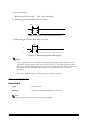
❏ AC characteristics:
Minimum reset pulse width:
TRS 1 msec (minimum)
❏ When using pin 6 (DSR) (DIP switch 2-7 is ON):
TRS
H
L
Figure 1-12 Minimum reset pulse width (pin 6)
❏ When using pin 25 (INIT) (DIP switch 2-8 is ON):
TRS
H
L
Figure 1-13 Minimum reset pulse width (pin 25)
Notes:
When a signal that does not satisfy the requirements above is input, printer operation is not
guaranteed. When a signal is input to pin 25 (INIT) at the TTL level, the requirements above
must also be satisfied. Although a signal is input to pin 6 (DSR) at the TTL level, according to the
DC characteristics described above, the operation is not guaranteed and pin 6 cannot be
controlled.
When pin 6 (DSR) and pin 25 (INIT) are open, the printer is operating.
Buttons and Switches
Power Switch
Type:
Rocker switch
Function:
The power switch turns the power on or off.
Note:
Turn on the power only after connecting the power supply.
1-18 Features and General Specifications
Rev. A
TM-T88 Series Technical Manual
Panel Button
Feed (FEED) button:
Non-locking push button
[Function] If you push this button once and release it, the printer
feeds paper for one line based on the line spacing set by
ESC 2 and ESC 3. If you hold down the button, the
printer will feed paper continuously.
Paper feeding using the FEED button cannot be
performed under the following conditions:
1.
The paper roll end sensor detects a paper end
2. When the printer cover is open.
If you push this button when the printer is in the
macro execution standby state, the defined macro is
executed.
During self-test printing, you can stop the self test
temporarily by pressing this button and restart it by
pressing the button again.
Note:
The ESC c 5 command enables or disables the panel button. When disabled, the button will not
function.
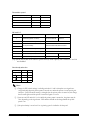
DIP Switches
For the serial interface model
The DIP switches are located at the bottom of the case.
DIP switch 1
DIP Switch
Function
ON
OFF
1
Data reception error
Ignored
Prints “?”
2
Receive buffer capacity
Data buffer 45 bytes
Data buffer 4 KB
3
Handshaking
XON/XOFF
DTR/DSR
4
Data word length
7 bits
8 bits
5
Parity check
Yes
No
6
Parity selection
Even
Odd
7
Transmission speed selection
Refer to Transmission Speed Table
8
Rev. A
Features and General Specifications 1-19
Transmission speed
Transmission Speed (BPS)
SW 1-7
SW 1-8
2400
ON
ON
4800
OFF
ON
9600
ON
OFF
19200
OFF
OFF
BPS: Bits Per Second
DIP switch 2
SW 2
Function
ON
OFF
1
Handshaking (BUSY condition)
Receive buffer full
Off line or receive
buffer full
2
Reserved (do not change settings)
Fixed to OFF
3
Selects print density
Refer to Print Density Selection Table
4
5
Reserved (do not change settings)
Fixed to OFF
6
Reserved (do not change settings)
Fixed to Off
7
I/F pin 6 reset signal (*1)
Enabled
Disabled
8
I/F pin 25 reset signal (*2)
Enabled
Disabled
(*1)(*2) With the RS-485 serial interface specification (a dealer option), DIP Switches 2-7 and 2-8
are disabled.
Print density selection
Print Density
SW 2-3
SW 2-4
1 (Light)
ON
ON
2
OFF
OFF
3
ON
OFF
4 (Dark)
OFF
ON
Notes:
❏ Changes in DIP switch settings (excluding switches 2-7 and 2-8 interface reset signals) are
recognized only when the printer power is turned on or when the printer is reset by using the
interface. If the DIP switch setting is changed after the printer power is turned on, the change
does not take effect until the printer is turned on again or is reset.
❏ If you turn on DIP switch 2-7 or 2-8 while the printer power is turned on, the printer may be
reset, depending on the signal state. DIP switches should not be changed while the printer
power is on.
❏ If the print density is set to level 3 or 4, printing speed is inclined to be low speed.
1-20 Features and General Specifications
Rev. A
TM-T88 Series Technical Manual
For parallel interface model
DIP switch 1
DIP Switch
Function
ON
OFF
1
Auto line feed
Always enabled
Always disabled
2
Receive buffer capacity
Data buffer 45 bytes
Data buffer 4kB
3-8
Not defined
—
—
DIP Switch
Function
ON
OFF
1
Handshaking (BUSY condition)
2
Reserved (do not change the
setting)
3
Selects print density
DIP switch 2
• Receive buffer full
• Data reading
• Off-line
• Receive buffer full
• Data reading
Fixed to OFF
Refer to print density selection table
4
5-7
Reserved (do not change the
setting)
8
I/F pin 31 reset signal (do not
change the setting)
Fixed to OFF
Fixed to ON
Print density selection
Print Density
SW 2-3
SW 2-4
1 (Light)
ON
ON
2
OFF
OFF
3
ON
OFF
4 (Dark)
OFF
ON
Notes:
❏ Changes in DIP switch setting (excluding 2-8, interface reset signal) are recognized only when the
printer power is turned on or when the printer is reset by using the interface. If the DIP switch
setting is changed after the printer power is turned on, the change does not take effect until the
printer is turned on again or is reset.
❏ If you turn on DIP switch 2-8 while the printer power is turned on, the printer may be reset,
depending on the signal state. DIP switches should not be changed while the printer power is on.
❏ If the print density is set to level 3 or 4, printing speed is inclined to be low speed.
Rev. A
Features and General Specifications 1-21
Panel LEDs
Power (POWER) LED:
Green
Error (ERROR) LED:
On:
Power is stable.
Off:
Power is not stable.
Red
On:
Off line (except during paper feeding using the
FEED button, self-test printing, and the error state)
Off:
Normal condition.
Blinking:
Error
Red
Paper roll end (PAPER
OUT) LED:
On:
The paper roll near end is detected.
Off:
Paper is loaded (Normal condition)
Blinking
Self-test standby state (See Chapter 4) or macro
standby state
Paper LED blinking pattern
State
PAPER LED Blinking Pattern
Recovery Conditions
Waiting for self-test printing
to be continued or macro
execution ready state.
PAPER OUT
Pressing the PAPER FEED
button causes self-test printing
to be continued or executes
the macro.
1-22 Features and General Specifications
Approx. 320 ms
Rev. A
TM-T88 Series Technical Manual
Note: A macro can be executed r times (r specifies the number of times to execute the macro)
within the specified definition range. The macro can be executed continuously or can be
executed by pressing the button. If the macro is executed by pressing the FEED button, the
PAPER LED blinks to indicate the macro execution ready state.
POWER
ERROR
PAPER
OUT
FEED
Figure 1-14 Panel Button and Indicators
Self-test
The printer has a self-test function that checks the following:
❏ Control circuit functions
❏ Printer mechanisms
❏ Print quality
❏ Control Software version
❏ DIP switch settings.
See Chapter 4 for instructions on running a self-test.
Hexadecimal Dump
Hexadecimal Dumping Function
This function prints the data transmitted from the host computer in hexadecimal numbers and
in their corresponding characters.
Performing a Hexadecimal Dump
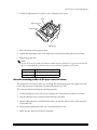
Open the cover and turn the power on while pressing the FEED button; then close the cover.
The printer first prints "Hexadecimal Dump" on paper roll and prints the received print data
in hexadecimal numbers and in its corresponding characters.
Rev. A
Features and General Specifications 1-23
Notes:
If no characters correspond to the data received, the printer prints ".".
Control commands are printed in bold for emphasis.
During hexadecimal dumping, any commands other than DLE EOT and
DLE ENQ do not function.
Insufficient print data to fill the last line can be printed by setting the printer
off-line.
Ending hexadecimal dumping
Hexadecimal dumping ends by turning the power off or resetting the printer via the
interface after printing has finished.
<Printing example>
1B 21 00 1B 26 02 40 40 . ! . . & .@ @
1B 25 01 1B 63 34 00 1B . % . . c4 . .
41 42 43 44 45 46 47 48 ABCDEFGH
Paper Sensors
The printer has 2 paper sensors as follows:
❏ Paper roll near-end sensor
The sensor which detects a near-end of a paper roll.
When the paper roll diameter becomes sufficiently small, the sensor detects a near-end of the
paper roll and the PAPER LED indicator lights. If the sensor is enabled by ESC c 4, the
printer stops printing.
❏ Paper roll end sensor
This sensor detects whether paper is present or not.
When the sensor detects a paper-end, the printer stops printing.
Note:
After installing new paper roll, close the printer cover; then the printer restarts printing.
1-24 Features and General Specifications
Rev. A
TM-T88 Series Technical Manual
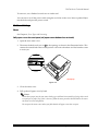
Cover Open Button
When the cover open button (located to the right of the cover) is pressed, the printer cover is
opened. When the cover is closed, the cover open button is latched.
Notes:
Be sure to use the cover open button to open the printer cover.
Do not open the cover during printing.
Do not open the cover during the auto-cutting operation; otherwise the mechanism may be damaged.
Cover Open Sensor
The cover open sensor monitors the printer cover. When the sensor detects a cover open during
printing, the error LED blinks and the printer stops printing. The printer recovers when the
cover is closed. When the sensor detects a cover open while the printer is in the standby status,
the printer goes off-line. The printer recovers when the cover is closed.
Note:
Whether the cover is open or not does not affect the status reported by the paper roll end sensor.
Print Buffer-full Printing
When subsequent data is received after the printer processes one line of data in the print buffer,
the printer automatically prints the processed line and feeds the paper by one line (in standard
mode).
Standard Accessories
❏ Paper roll (diameter 50 mm [1.96"]) × 1 roll
❏ Operator's Manual
❏ I/F fixing screw (hexagonal millimeter screw) (for serial interface model only)
Options
❏ External power supply: PS-170
❏ Affixing tapes (model: DF-10)
❏ Wall hanging bracket (model: WH-10)
❏ RS-485 interface board is equipped as a dealer option
Note:
Use only the EPSON PS-170 power supply to avoid damage to the printer and the power supply.
Rev. A
Features and General Specifications 1-25
Consumables
Specified thermal roll paper: NTP080-80
In Japan: Nakagawa Seisakujo
In U.S.A.: Nakagawa Mfg. (USA) Inc.
In Europe: Nakagawa Mfg. (Europe) GmbH
In Southeast Asia: N.A.K. Mfg. (Malaysia) SDN BHD
[Original paper: TF50KS-E Nippon Paper Industries Co., Ltd.]
The following paper can be used instead of the specified paper above:
Original paper:
PD160R New Oji Paper Mfg. Co., Ltd.
AF50KS-E Jujo Thermal Oy (Finland)
F380 Kanzaki Specialty Papers, Inc. (U.S.A.)
Note:
Do not use any paper other than these specified above. Otherwise, print head reliability and print
quality are affected adversely.
Ribbon Cassette
ERC-31(P)
In Japan:
EPSON HANBAI Co., LTD.
In U.S.A.:
EPSON America Inc.
In Europe:
EPSON Europe B.V.
1-26 Features and General Specifications
Rev. A
TM-T88 Series Technical Manual
External Power Supply PS-170 Specifications
Input specifications
Rated input voltage
90 to 264 V AC
Rated frequency
50/60 Hz ± 3 Hz
Rated input current
less than 100 V A
Power switch
None
Power LED
None
Output specifications
Output voltage
24 VDC ± 5%
Rated output current
2.0 A
Rated output power
Approximately 48 W
Output peak current
4.5 A (within 300ms duty 1/6)
Rev. A
Features and General Specifications 1-27
TM-T88 Series Technical Manual
Chapter 2
Mechanisms and Operation
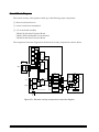
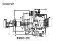
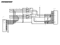
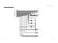
Component Connection Diagram
This printer is made up of the following major components:
❏ M-T88 Printer Mechanism (Switch circuit board assembly-B)
❏ I/F circuit board assembly
❏ Main circuit board unit-A
The block diagram for this printer is shown below.
Host computer
Drawer
Power
supply
unit
M-T88 printer mechanism
CN1
CN2
CN1
I/F circuit board assembly
CN2
Thermal
head
CN502
Auto cutter
Cover
open
sensor
CN3
CN4
CN4
Main circuit board unit-A
CN
501
CN
1
Switch circuit board assembly- B
CN
5
Power
switch
CN2
CN5
CN6
Paper
feed motor
Paper
near-end
sensor
Paper
sensor
Figure 2.1.1 Component connection diagram
Rev. A
Mechanisms and Operation 2-1
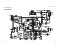
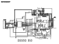
Circuit Block Diagram
The control circuitry of this printer is made up of the following major components:
❏ Main circuit board unit-A
❏ Switch circuit board assembly-B
❏ I/F circuit board assembly
UB-S01: RS-232 Serial Universal Board
UB-P01: IEEE 1284 Parallel Universal Board
UB-S02: RS-485 Serial Universal Board
The component connection diagram for the electrical circuitry components is shown below.
Address bus
ROM
for "M"
version
ROM
CPU
RAM
I/F circuit
board
assembly
CN1
Host
interface
Reset
circuit
CN2
CN4
Gate
array
Host
interface
circuit
Dip switches
CN3
Sensor
circuits
Auto cutter
CN502
Auto cutter
drive circuit
CN2
Drawer
kick
circuit
Drawer
_
+
Power
supply
circuit
CN5
CN4
Cover
sensor
CN6
+24F
Malfunction
protection
circuit
CN1
Power
supply unit
M-T88
printer
mechanism
VCC
+24V
Main circuit board unit-A
Paper
sensor
Thermal head
drive circuit
CN2
Paper feed
motor
drive circuit
Control
panel
circuit
CN5
CN501
CN1
Paper
near-end sensor
Paper
feed motor
LED, SW
Switch circuit board assembly-B
Power switch
Figure 2.2.1 Electrical circuitry component connection diagram
2-2 Mechanisms and Operation
Rev. A
TM-T88 Series Technical Manual
Memory Map
The following components are mapped in the memory map of this printer:
❏ CPU
❏ FLASH ROM (program U6, multi-lingual UN10)
❏ PS-RAM (pseudo static RAM)
Chip select signal
(automatic selection by CPU)
000000H
CPU on-chip I/O
00007FH
000080H
RAM
receive buffer,
printer buffer, etc.
CS1 = 0
01FFFFH
200000H
Undefined
3FFFFFH
400000H
Gate arrays
(I/O, other)
CS0 = 0
4000FFH
400100H
Undefined
7FFFFFH
800000H
ROM (UN10)
multi-lingual character
generator
CS3 = 0
87FFFFH
880000H
Undefined
F7FFFFH
F80000H
Undefined
FBFFFFH
FC0000H ROM (when
U6 is 2M)
FFFFFFH
ROM (when
U6 is 4M)
program
character
generator
CS2 = 0
program
character
generator
Figure 2.3.1 Memory map
Rev. A
Mechanisms and Operation 2-3
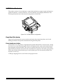
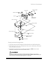
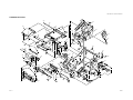
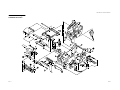
M-T88 Printer Mechanism
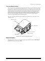
This printer consists of six mechanisms: a paper feed mechanism, a paper supply mechanism, a
printer mechanism, a cutter mechanism, a cover mechanism, and a display mechanism. The
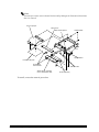
following illustration shows the external configuration of the M-T88.
Figure 2.4.1 M-T88 external configuration
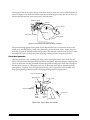
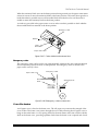
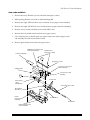
Paper Feed Mechanism
Paper feed is performed by a power transfer mechanism that rotates the platen, and a head
holding mechanism that presses the thermal head against the platen.
Power transfer mechanism
On the frame cover, the platen is supported by the platen shaft holder so it turns freely. Closing
the frame cover causes the platen gear affixed to the platen shaft to mesh with the deceleration
gear equipped on the main frame. The rotary force (in the direction of arrow (1)) of the receipt
paper feed motor affixed to the main frame is transferred in sequence to the motor gear (press fit
to the motor shaft), the deceleration gear, and the platen gear, which rotates the platen in the
direction of arrow (2).
A PM type stepping motor is used for the receipt paper motor.
2-4 Mechanisms and Operation
Rev. A
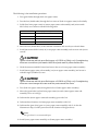
TM-T88 Series Technical Manual
A separate type gear train is used for this mechanism. When the motor rotates in reverse, the
pressure angle relationship causes power to work in the direction that the gear train is
separated, so reverse motor operation is impossible.
Cover, frame
Shaft holder platen
Gear, platen
2
Platen
Gear, reduction
Shaft holder platen
Motor, paper, receipt
Gear, motor
1
Figure 2.4.2 Power transfer mechanism
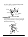
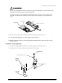
Head holding mechanism
Spring pins, which act as bearings, are press fit onto either side of the thermal head. The thermal
head bearings are inserted into slots equipped in the main frame. The head holding plate affixed
to the main frame has two head holding springs that apply pressure to the back of the thermal
head. While the frame cover is open, the thermal head is in contact with the stopper equipped on
the main frame.
Thermal head
Spring, head holding
Shaft holder platen
Plate, head holding
Frame, main
Figure 2.4.3 Head holding mechanism
Rev. A
Mechanisms and Operation 2-5
Closing the frame cover causes the top of the heat shield to come into contact with the platen as
shown in Figure 2.4.4. The thermal head separates from the stopper in the direction of arrow (3),
and the thermal head tip comes into contact with the platen.
Radiation plate
Platen
3
Cover, frame
Head tip
Spring, head holding
Paper guide
Figure 2.4.4 Platen and thermal head contact
The pressure being applied to the platen by the thermal head acts as downward force on the
frame cover, and the platen is fixed in the positioning slot in the main frame. At this time, the
slots that support the thermal head bearings open in the direction of the back of the head, so the
thermal head can move along the platen applying constant pressure along the print line.
Paper feed operation
Opening the frame cover, installing roll paper, and re-closing the frame cover causes the roll
paper to be sandwiched between the thermal head and platen. When the platen is rotated by the
power of the motor, friction generated between the platen and the paper feeds the roll paper in
the direction of arrow (3). This printer uses one of three print feed speeds, depending on the
print pattern. 2-2 phase drive for high-speed printing, and 1-2 phase drive for medium- and
slow-speed printing maintains torque while suppressing motor heat generation.
Paper feed direction
Thermal head
Cover, frame
Platen
Plate, head holding
Spring,
head
holding
Paper
sensor
(paper
end)
Roll paper
Paper guide
Figure 2.4.5 Paper feed mechanism
2-6 Mechanisms and Operation
Rev. A
TM-T88 Series Technical Manual
Head open mechanism
The printer uses a drop-in paper roll system, and the thermal head is exposed whenever the
frame cover is open (head open mechanism). In addition to simplifying paper loading, this
design also makes paper jam clearing and platen cleaning quicker and easier.
Thermal head
Platen
Main frame
Paper guide
Frame cover
Figure 2.4.6 Frame cover open
Rev. A
Mechanisms and Operation 2-7
The paper outlet of the printer is covered, and even if paper output becomes blocked for some
reason, there is enough room in the space between the platen and frame cover for accumulation
of two or three normal length receipts (the length of one sheet is assumed to be 80mm or less).
This reduces the chance of receipt paper becoming bent and of the print pitch becoming uneven.
Paper that accumulates can be easily pulled out of the printer after the paper outlet is opened.
Thermal
head
Platen
Paper guide
Roll paper
Figure 2.4.7 Roll paper behavior during paper output blockage
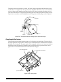
Paper Supply Mechanism
The roll paper guide, which holds the paper roll, is affixed to the main frame. The side walls of
the paper guide are shaped so they continue up to the thermal head to limit lateral movement of
the paper as it is being fed. The paper guide is also equipped with a near end sensor mechanism
that detects when the amount of remaining roll paper drops below a prescribed level, and a
paper end sensor mechanism that detects the end of the roll paper.
near end sensor tab
paper guide inner surface
paper end sensor
Figure 2.4.8 Paper guide
2-8 Mechanisms and Operation
Rev. A
TM-T88 Series Technical Manual
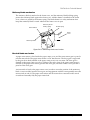
Near end sensor mechanism
The near end (N.E.) sensor lever is supported by the N.E. sensor holder so it can move. The
spring force of the microswitch fixed by a screw to the N.E. sensor holder presses the N.E. sensor
lever in the direction of arrow (1) in Figure 2.4.9. The microswitch is linked to the switch circuit
board assembly-B by the N.E. sensor lead wire. The N.E. sensor holder is attached to the paper
guide by the sensor adjustment screw.
When the paper roll is larger than the prescribed roll paper diameter, the pressure of the outer
surface of the paper roll on the N.E. sensor lever causes the lever to press the microswitch,
maintaining it in an ON state.
When the remaining paper on the roll is below the prescribed diameter, contact between the tip
of the N.E. sensor lever and the paper roll surface is broken, causing the lever to move in the
direction of arrow (1), into the core of the paper roll. This causes the microswitch to turn off,
indicating near end of the roll paper.
The prescribed near end roll paper amount can be changed between two different levels: one
with the N.E. sensor tab fixed in a raised position, and one with the N.E. sensor tab fixed in a
lowered position.
Sensor
adjustment
screw
N.E. sensor
holder
Paper roll
Microswitch
Paper roll
Core
Core
N.E.
sensor
lever
1
1
Large diameter roll
Small diameter roll
Figure 2.4.9 Near end sensor mechanism
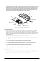
Paper end sensor mechanism
A reflective type photosensor, which consists of an LED and phototransistor, is mounted on the
paper sensor board and located in the paper guide paper path. When the end of the roll paper
passes the sensor, the volume of light from the LED that makes it to the phototransistor changes.
Because the reflectance ratios of the paper and the rubber platen surface are different, a change
in the output level of the phototransistor is detected as the end of the paper.
Rev. A
Mechanisms and Operation 2-9
The shield plate provided around the sensor is grounded to the main frame. This printer is
designed so that the sensors are exposed when the frame cover is open, but the shield plate acts
as a lightning rod to protect sensors against electrostatic damage. The paper sensor board is
linked to the switch circuit board assembly-B by the paper sensor lead.
Paper guide
Photosensor
Shield plate
Main frame (bottom)
Figure 2.4.10 Paper end sensor mechanism
Printer Mechanism
The thermal head is designed so its heating element is positioned where it comes into contact
with the platen. The roll paper wrapped around the platen is kept in contact with the thermal
head’s heating element at a prescribed pressure, and printing is performed when heat is
generated by the heating element.
This printer employs a thick-film thermal head that consists of a head tip with a heating element,
a driver IC for driver control of the heating element, a thermistor that monitors the temperature
of the thermal head, a heat shield that protects the head tip against abnormal heat, a print circuit
board that is linked to the signal line, and head support shafts (spring pins).
The thermal head is connected to the main circuit board unit-A by an FFC connected to the
connector. Figure 2.4.12 shows a cross section of the thermal head heating unit and the (thermal)
roll paper.
Printing is performed according to the following steps:
1. The print signal sends a prescribed energizing pulse to the electrodes that correspond to
each dot to be printed.
2. Resistors at each electrode generate heat.
2-10 Mechanisms and Operation
Rev. A
TM-T88 Series Technical Manual
3. The heat energy generated by the resistors is transmitted to the roll paper surface through
the protective layer to the paper’s heat sensitive layer, causing coloration of the paper.
Head tip
Radiation plate
Spring pin
Print circuit board
Spring pin
Connector
Figure 2.4.11 Thermal head configuration
Heat
sensitive
layer
Electrode
Resistor
Board
Base
Protective
layer
Figure 2.4.12 Thermal paper and thermal head
Data input and printing
Serial print data input from DATA IN is synchronized with the clock, transferred to the shift
register, and the print data is stored in the latch in accordance with the latch signal. The stored
print data turns on the gate in accordance with the STROBE signal, which energizes the heating
element.
There are two strobe pins, STROBE 1 and STROBE 2, and the drive operation is divided between
them.
Rev. A
Mechanisms and Operation 2-11
The width of the energizing pulse is set to the optimum value in accordance with the paper feed
speed, the temperature picked up by the thermistor, the head supply voltage, whether or not a
dot was printed at the previous position, and the print pattern.
uh
0.1ÊF
50V
dot512
GND
rh W
dot217
V
U
T
dot216
S
dot1
R
Q
P
bkj
k`s
rsqQ
rsqP
udd
0.1ÊF 50V
fmc
Thermistor
T
[~X^
sl
sl
Figure 2.4.13 Thermal head block diagram
Cutter Mechanism
This printer is equipped with an auto cutter mechanism for cutting of the roll paper, and an
emergency cutter for manual cutting.
Auto cutter mechanism
The auto cutter has two opposing cutter blades that operate like a scissors to cut the paper. It is a
separate cutter blade type mechanism that does not require passage of the roll paper through an
auto cutter mechanism slit. Opening the frame cover causes the stationary blade to separate
completely from the moving blade. The stationary blade is fixed to the frame cover, while the
moving blade is attached to the main frame.
Stationary blade (lower)
Stationary blade
holding spring
Movable blade
holding spring
Movable blade
(upper)
Figure 2.4.14 Scissors type cutter mechanism
2-12 Mechanisms and Operation
Rev. A
TM-T88 Series Technical Manual
Stationary blade mechanism
The stationary blade is attached to the frame cover, and the stationary blade holding spring
presses the stationary blade against the frame cover. A blade shutter is installed on the frame
cover, where it is pulled by the shutter spring. The blade shutter is a safety mechanism that
keeps the stationary blade covered whenever the frame cover is open.
Blade shutter
Stationary blade
holding spring
Shutter spring
Frame
cover
Stationary blade
Figure 2.4.15 Stationary blade mechanism
Movable blade mechanism
A paper cutter motor is fixed inside the paper cutter cover, and the cutter motor gear is press fit
onto the motor shaft. The paper cutter motor is a DC brush motor. The drive gear is supported
by the gear drive shaft (caulked to the paper cutter cover) so it can rotate. The drive gear is
retained on the paper cutter cover by a push nut. The rotary force of the paper cutter motor is
reduced by the paper cutter motor gear and the drive gear, and then rotates a drive pin that is
press fit to the drive gear.
A microswitch is fixed to the paper cutter cover in order to sense the position of the stationary
blade. A cam is molded onto the driver gear, and engagement with this cam repeatedly turns the
microswitch on and off. The paper cutter motor and microswitch are connected to the switch
circuit board assembly-B by the paper cutter lead.
Rev. A
Mechanisms and Operation 2-13
The movable blade support, spacer, movable blade, movable blade holding spring, and movable
blade spring washer are equipped on the movable blade shaft, which is caulked to the paper
cutter frame. The drive pin fits into an oblong hole in the movable blade, and rotation of the
drive pin causes the movable blade to rotate left and right on the movable blade shaft. The
microswitch is off (open) when the movable blade is in the wait state.
Stationary blade
Paper cutter cover
Movable blade
shaft
Movable
blade
Drive gear
Lead
Drive pin
Microswitch
Paper cutter motor
Figure 2.4.16 Movable blade mechanism
Auto cutter operation
The frame cover can be closed while the movable blade is in the home position. Closing the
frame cover causes a shaft in the main frame to push up the blade shutter, exposing the
stationary blade. Also, the stationary blade is brought into partial contact with the paper cutter
frame, and the stationary blade and movable blade are put into opposition. This is the auto
cutter enabled state.
The following is a step-by-step description of an auto cut operation:
1. Application of voltage between paper cutter motor terminals causes the motor to rotate
clockwise.
2. The drive pin moves the movable blade towards the stationary blade.
3. The movable blade and stationary blade intersect to cut the paper from right to left.
4. An uncut portion is retained on the left and the movable blade returns.
5. The microswitch detects when the movable blade returns to the home position, motor
operation is stopped, and movable blade operation is stopped.
Cutter blade knob
The movable blade is in the home position whenever cutter operation is not being performed. In
addition to safety considerations, this enables a mechanism in which the frame cover cannot be
opened or closed while the movable blade is not in the home position.
2-14 Mechanisms and Operation
Rev. A
TM-T88 Series Technical Manual
When the stationary blade is not in the home position during normal use, the paper cutter motor
rotates in reverse to move the stationary blade to the home position. The cutter motor gear has a
knob that makes it possible to move the movable blade when the drive force of the motor is
unable to return the stationary blade to the home position.
A window is provided in the paper cutter cover in order to make it possible to check whether
the movable blade has returned to the home position.
Emergency cutter
Window
Cutter
blade knob
Paper cutter cover
Figure 2.4.17 Cutter blade knob external view
Emergency cutter
The emergency cutter can be used to cut paper manually whenever the auto cutter mechanism
does not operate properly because of some problem. The emergency cutter is affixed to the
paper cutter cover by screws.
Paper cutter cover
Movable
blade
Emergency cutter
Stationary blade
Figure 2.4.18 Emergency cutter cross section
Cover Mechanism
A roll paper cover is fixed to the frame cover. The roll paper cover ensures the strength of the
cover section. The frame cover passes through the cover shaft, allowing the roll paper cover to
hinge on the main frame. A cover spring affixed to the main frame comes into contact with the
shaft on the frame cover, providing optimum load when the frame cover is opened and closed.
Rev. A
Mechanisms and Operation 2-15
switch circuit board assembly-BSince the printer mechanism, including the auto cutter, will not
operate properly if the frame cover is not closed correctly, a cover open sensor mechanism is
equipped to detect when the frame cover is not closed correctly. A cover open button
mechanism is also provided to partially open the cover.
Shaft
Frame
Switch circuit
board assembly-B
Cover spring
Main frame
Cover shaft
Figure 2.4.19 Cover spring external configuration
Cover open sensor mechanism
A transmissive type photosensor, consisting of an LED and phototransistor, is mounted on the
cover open board, and affixed to the main frame. The frame cover is shaped so it fits into the
photosensor, and closing of the frame cover causes the cover to enter into the photosensor slit,
cutting the optic axis. When the frame cover is raised, on the other hand, photosensor light
passes through the slit. This makes it possible to detect whether or not the cover is open by
monitoring the output level of the photo transistor.
Frame cover
Main frame
Photosensor
Figure 2.4.20 Cover open sensor mechanism
2-16 Mechanisms and Operation
Rev. A
TM-T88 Series Technical Manual
Cover open button mechanism
The cover open lever is supported by the main frame shaft. The cover open button along with its
return spring is supported by the side of the paper guide. Pressing the cover open button while
the frame cover is closed causes part of the cover open button to link with the cover open lever,
which rotates the cover open lever. The cover open lever pushes up the shutter blade, which
pushes up the frame cover. The platen pushes up the thermal head, separating them. This
removes the force stopping the frame cover, making it possible to open the frame cover with
little power. When the operator releases the cover open button, the cover open button is
returned to its prescribed position by the return spring.
The cover can also be opened by directly pulling up on the thermal cover AA (plastic cover)
with strong force.
Thermal cover AA
Display panel
Cover open lever
Cover open button
Blade shutter
Figure 2.4.21 Cover open button mechanism
Display Mechanism
The display panel, which is located inside the paper guide, has three LEDs (POWER, ERROR,
PAPER OUT) and one push-button (FEED).
Rev. A
Mechanisms and Operation 2-17
In order to simplify maintenance, signal lines such as motors and sensors (except for the thermal
head signals) are all connected to the switch circuit board assembly-B by the leads and
connectors, and switch circuit board assembly-B is connected by FFC to the main circuit board
unit-A. The switch circuit board assembly-B is affixed to the arm coming out of the main frame.
The control panel LEDs and push-button are mounted on switch circuit board assembly-B.
Display panel
LED
Push-button
Switch board assembly-B
Figure 2.4.22 Switch circuit board assembly-B external configuration
Main Circuit Board Unit-A
The main circuit board unit-A is made up of the following electrical circuits:
❏ CPU and CPU Peripheral Logic Circuits
CPU
RAM
ROM
Gate array
Reset circuit
❏ M-T88 Control Circuits
Thermal head drive circuit
Paper feed motor drive circuit
Auto cutter drive circuit
Detector circuits
❏ Operation Panel Control Circuits
❏ DIP Switch Read Circuit
❏ Malfunction Protection Circuit
❏ Drawer Kick Control Circuit
2-18 Mechanisms and Operation
Rev. A
TM-T88 Series Technical Manual
❏ Power Supply Circuits
Filter circuit
+24V output circuit
+5V output circuit
CPU and CPU Peripheral Logic Circuits
CPU
The CPU (U4) of this printer has an 8-bit external data bus, a 16-bit internal data bus, and a
19.66MHz external clock. The CPU (U4) controls the printer in accordance with the printer
control program written in flash ROM (U6). The following table shows the function of each CPU
pin.
CPU signal assignments and functions
No.
Pin name
1
Function
I/O
Level
P65
Not used. Open
O
TTL
2
P70
Not used. Open
O
TTL
3
P71
Not used. Open
O
TTL
4
P72
Not used. Open
O
TTL
5
P73
Not used. Open
O
TTL
6
P74
RPF_+A
Receipt side
O
TTL
7
P75
RPF_+B
Paper feed motor drive control: 2-2 phase drive
O
TTL
8
P76
RPF_-A
OR 1-2 phase drive
O
TTL
9
P77
RPF_-B
All terminals ON (L): hold
O
TTL
10
NMI
NMI
Not used. +5V direct connection
I
TTL
11
P80/TXD0
TXD
HOST I/F SD L:ON
O
TTL
12
P81/RXDO
RXD
HOST I/F RD L:ON
I
TTL
13
P82/
SCLKO
CLK IN/DTR
HOST I/F CLK IN/DTR
O
TTL
14
P83
CLK REQ
HOST I/F CLK REQ
O/I
TTL
15
P84
CTS
HOST I/F CTS L:ON
O
TTL
16
P85
DET
HOST I/F DET
I
TTL
17
AGND
AGND
(A/D converter) GND terminal
I
(0V)
18
VREF
VREF
A/D converter reference voltage
I
(+5V)
19
VCC
VCC
Main power supply terminal (+5V)
I
(+5V)
20
P90/AN0
AN0OUT
V DTC: +24V power supply voltage value detection
I
Analog
21
P90/AN1
AN1OUT
RRE: Receipt paper detect signal
I
Analog
22
P90/AN2
AN2OUT
THR: receipt head temperature detect signal
(thermal head)
I
Analog
23
P90/AN3
Not used. Open
I
Analog
24
AM8/16
+5V direct connection
I
TTL
Rev. A
Signal name
AM8/16
Mechanisms and Operation 2-19
CPU signal assignments and functions (continued)
No.
Pin name
Signal name
Function
I/O
Level
25
CLK
CLK
Not used. Open
O
TTL
26
GND
GND
GND terminal
I
(0V)
27
X1
X1
Crystal connection
I
----
28
X2
X2
Crystal connection
O
----
29
EA
EA
GND direct connection
I
TTL
30
RESET
RESET
CPU reset input; L: ON
I
----
31
WDTOUT
WDTOUT
Watchdog timer error detect; L: error
O
TTL
32
PAO
Not used. Open
O
TTL
33
PA1
Not used. Open
O
TTL
34
PA2/TO1
Not used. Open
O
TTL
35
PA3
Not used. Open
O
TTL
36
PB0/INT4
Not used. Open
I
TTL
37
PB1
Not used. Open
O
TTL
38
PB2
Not used. Open
O
TTL
39
PB3
Receipt paper feed motor common power supply;
H: ON
O
TTL
40
PB4/INT6
Not used. Open
I
TTL
41
PB5
AC_1
Auto cutter drive signal 1
O
TTL
42
PB6
AC_2
Auto cutter drive signal 2
O
TTL
43
PB7
AC_RST
Auto cutter position detect (reset)
I
TTL
44
VCC
VCC
Main power supply terminal (+5V)
I
(+5V)
45
46
47
48
49
50
51
52
D0
D1
D2
D3
D4
D5
D6
D7
D0
D1
D2
D3
D4
D5
D6
D7
Data bus
3 state
TTL
53
P10
RNE
Receipt paper near end detect; H: paper out
I
TTL
54
P11
R_COVER
Receipt printer cover open detect; L: close
I
TTL
55
P12
RCPT_FD_SW
Receipt paper feed switch; L: ON
I
TTL
56
P13
DK_S
Drawer open/close; L: open
I
TTL
57
P14
ROUT_LED
Receipt roll paper out LED; L: ON
O
TTL
58
P15
PTLED_COM
Receipt paper detect LED drive signal; L: ON
O
TTL
59
P16
RERR_LED
Receipt printer error LED; L: ON
O
TTL
60
P17
HCTS
HOST I/F HCTS
O
TTL
61
62
GND
GND
GND terminal
I
(0V)
RPFCOM
2-20 Mechanisms and Operation
Rev. A
TM-T88 Series Technical Manual
CPU signal assignments and functions (continued)
No.
Pin name
Signal name
Function
I/O
Level
64
65
66
67
68
A23
A22
A21
A20
A19
A23
A22
A21
A20
A19
Address bus. Not used. Open
Address (A19 to A323)
O
TTL
69
70
71
72
73
74
75
76
77
78
79
80
81
82
83
84
85
86
87
A18
A17
A16
A15
A14
A13
A12
A11
A10
A9
A8
A7
A6
A5
A4
A3
A2
A1
A0
A18
A17
A16
A15
A14
A13
A12
A11
A10
A9
A8
A7
A6
A5
A4
A3
A2
A1
A0
Address bus
O
TTL
88
RD
RD
External data read signal
O
TTL
89
WR
WR
External data write signal
O
TTL
90
P52
Not used. Open
I
TTL
91
P53
Not used. Open
I
TTL
92
P54
Not used. Open
I
TTL
93
P55
Not used. Open
I
TTL
94
CSO
CSO
Gate array select signal; L: ON
O
TTL
95
VCC
VCC
Main power supply terminal (+5V)
I
(+5V)
96
CS1
CS1
RAM chip select signal; L: ON
O
TTL
97
CS2
CS2
ROM (U6) chip select signal; L: ON
O
TTL
98
CS3
CS3
ROM (UN10) chip select signal; L: ON
O
TTL
99
RAS
RAS
Not used. Open
O
TTL
100
GND
GND
GND terminal
I
(0V)
RAM (1M bit)
RAM is used for temporary storage of the following:
❏ Data received from the interface (receive buffer)
❏ Pattern data printed by the print head unit (printer buffer)
❏ Data used for CPU (U4) routines (flags, pointers, etc.)
Rev. A
Mechanisms and Operation 2-21
ROM (2M or 4M bits)
A printer control program and character generator data is written into FLASH ROM (U6). The
control program controls basic printer operations, and all CPU (U4) control is performed in
accordance with this program.
Gate array
The gate array (U5) of this printer controls power to the impact head and thermal head. It is
equipped with four 8-bit I/O ports, PS-RAM controller, and a +24V control time-limit circuit.
The gate array has its own independent 8MHz external clock. The table below shows the
function of each gate array pin.
Gate array signal assignments and functions
No.
Pin name
Signal name
Function
I/O
Level
1
TEST
TEST
Connected to GND
I
TTL
2
RAMCS
RAMCS
RAM chip select signal; L: ON
I
TTL
3
GACS
GACS
Gate array select signal; L: ON
I
TTL
4
WR
WR
Data write signal
I
TTL
5
RD
RD
Data read signal
I
TTL
6
PSCE
PSCE
PS-RAM (U-7) chip select signal; L: ON
O
TTL
7
VDD
VDD
Main power supply terminal (+5V)
I
(+5V)
8
9
10
11
12
13
14
A6
A5
A4
A3
A2
A1
A0
A6
A5
A4
A3
A2
A1
A0
Address bus
I
TTL
15
VSS
VSS
GND terminal
I
(0V)
16
17
18
19
20
21
22
23
D7
D6
D5
D4
D3
D2
D1
D0
D7
D6
D5
D4
D3
D2
D1
D0
Data bus
3 state
TTL
24
VSS
VSS
GND terminal
I
(0V)
25
VDD
VDD
Main power supply terminal (+5V)
I
(+5V)
26
PB7
Not used. Open
O
TTL
27
SW24V_1
Not used. Open
O
TTL
28
SW24V_2
SW24V2
Printer mechanism +24V time-limit power; H: ON
O
TTL
29
RTS
RTS
HOST I/F RTS L:ON
O
TTL
30
SCLK
CLK IN/DTR
HOST I/F CLK IN/DTR
I
TTL
31
RESET
RESET
Reset input; L: ON
I
-------
32
VSS
VSS
GND terminal
I
(0V)
2-22 Mechanisms and Operation
Rev. A
TM-T88 Series Technical Manual
Gate array signal assignments and functions (continued)
No.
Pin name
33
Function
I/O
Level
HEAD1
Not used. Open
O
TTL
34
HEAD2
Not used. Open
35
HEAD3
Not used. Open
36
HEAD4
Not used. Open
37
HEAD5
Not used. Open
38
HEAD6
Not used. Open
39
HEAD7
Not used. Open
40
VSS
VSS
GND terminal
I
(0V)
41
VDD
VDD
Main power supply terminal (+5)
I
(+5V)
42
HEAD8
Not used. Open
O
TTL
43
HEADCOM
Not used. Open
O
TTL
44
P13
Not used. Open
I
TTL
45
46
47
P12
P11
P10
Not used. Open
I
TTL
48
VSS
VSS
GND terminal
I
(0V)
49
XOUT
XOUT
Crystal connection.
O
50
XIN
XIN
Crystal connection
I
-------
51
VDD
VDD
Main power supply terminal (+5)
I
(+5V)
52
PC7
DSW18
DIP switch setting signal DSW1-8
I
TTL
53
PC6
DSW17
DIP switch setting signal DSW1-7
54
PC5
DSW16
DIP switch setting signal DSW1-6
55
PC4
DSW15
DIP switch setting signal DSW1-5
56
PC3
DSW14
DIP switch setting signal DSW1-4
57
PC2
DSW13
DIP switch setting signal DSW1-3
58
PC1
DSW12
DIP switch setting signal DSW1-2
59
PC0
DSW11
DIP switch setting signal DSW1-1
60
VSS
VSS
GND terminal
I
(0V)
61
PD7
MSL2
Thermal (receipt) printer connected/not connected; H:
connected
I
TTL
62
PD6
MSL1
Slip printer connected/not connected; L: not connected
I
TTL
63
PD5
DSW26
DIP switch setting signal DSW2-6
I
TTL
64
PD4
DSW25
DIP switch setting signal DSW2-5
65
PD3
DSW24
DIP switch setting signal DSW2-4
66
VSS
VSS
GND terminal
I
(0V)
67
VDD
VDD
Main power supply terminal (+5)
I
(+5V)
68
PD2
DSW23
DIP switch setting signal DSW2-3
I
TTL
69
PD1
DSW22
DIP switch setting signal DSW2-2
70
PD0
DSW21
DIP switch setting signal DSW2-1
Rev. A
Signal name
Mechanisms and Operation 2-23
Gate array signal assignments and functions (continued)
No.
Pin name
71
Signal name
Function
I/O
Level
PE7
Not used. Open
I
TTL
72
PE6
Not used. Open
O
TTL
73
PE5
Not used. Open
O
TTL
74
PE4
Not used. Open
O
TTL
75
PE3
Not used. Open
O
TTL
76
PE2
O
TTL
77
PE1
O
TTL
78
PE0
O
TTL
79
VSS
GND terminal
I
(0V)
80
PF7
Not used. Open
O
TTL
81
PF6
Not used. Open
O
TTL
82
PF5
Not used. Open
O
TTL
83
PF4
Not used. Open
O
TTL
84
PF3
PF3
Not used. Open
O
TTL
85
PG4
PG4
86
PG3
PG3
87
PG2
PG2
88
PG1
PG1
89
PG0
PG0
90
VSS
VSS
GND terminal
I
(0V)
91
VDD
VDD
Main power supply terminal (+5)
I
(+5V)
92
RSCLK
RSCLK
Thermal head clock signal
O
TTL
93
RSI
RSI
Thermal head serial data signal
94
RLT
RLT
Thermal head latch signal
95
RSTB2
RSTB2
Thermal head strobe signal 2
96
RSTB1
RSTB1
Thermal head strobe signal 1
97
PF2
PF2
Not used. Open
O
TTL
98
PF1
DKD2
Drawer kick driver signal 2; L: ON
O
TTL
99
PF0
DKD1
Drawer kick driver signal 1; L: ON
O
TTL
100
VSS
VSS
GND terminal
I
(0V)
VSS
Reset circuit
The reset circuit protects against runaway CPU processing during unstable voltages
immediately after power up, abnormal printing, and other unforeseen operation. Output of the
OUT pin (PIN 6) of the reset IC (Us) is supplied to the CPU (U4) as a RESET input signal (PIN
30). The reset ICC (U2) monitors +5V voltage, and release the CPU reset when voltage rises
above 4.5V, which enable printer operation. The reset IC (U2) C terminal (PIN 5) is connected to
the reset signal (DSR signal or PIN 25 input signal) from the host interface, via DIP switch 2-7 or
2-8. Reset signals can be supplied power to cause reset IC output to become low, which resets
the CPU.
2-24 Mechanisms and Operation
Rev. A
TM-T88 Series Technical Manual
Reset from the host interface differs in accordance with interface specifications, as shown below.
RS-232C interface specifications
Selection between two signals (DSR signal or PIN 25 input signal) is possible.
1284 parallel interface specifications
Always use the #25 RESET signal. DIP switch 2-8 is always on. With the 1284 parallel interface,
this printer can be reset from the host interface signal’s nInit signal (PIN 31).
M-T88 Control Circuit
Thermal head drive circuit
The print head of the receipt printer mechanism is a thermal type print head with 512 dots per
line. All print head control is performed via a gate array. A driver is built into the print head,
and sending of print signal RSI, which is synchronized with the RSCKL signal, to the driver sets
the print/non-print status of each dot. Data is confirmed by latch signal RLT. Print time control
is performed by RSTB1 and RSTB2, while energizing time is controlled by the gate array.
Changes in head temperature causes fluctuation of the resistance value of the thermistor built
into the head, which is output as temperature signal THR. This signal is read by the analog port
of the CPU (U4).
Paper feed motor drive circuit
The paper feed motor has a precise angle of rotation (highly precise movement amount), and
allows control of motor speed. When RPFCOM signal of the CPU (U4) goes H, +24V are applied
to the COM terminal of the paper feed motor coil, and RPF_+A, RPF_-A, RPF_+B, and RPF_-B
change between H and L. The H/L change speed of RPF_+A, RPF_-A, RPF_+B, and RPF_-B
determines the speed of the motor. RPFCOM signal of the CPU (U4) changes back to L after the
paper feed operation is complete.
Auto cutter drive circuit
The auto cutter drive uses a TA8428K DC motor dedicated IC. Signals AC_1 and AC_2 from the
CPU (U4) performs clockwise and counterclockwise operation, and braking of the auto cutter.
AC_1
AC_2
Operation
L
L
Off
H
L
Clockwise
L
H
Counterclockwise
H
H
Brake
Detector circuits
Paper end sensor circuit
The thermal printer mechanism is equipped with a paper end sensor, which is connected via
switch circuit board assembly-B to the main circuit board unit-A. The paper end sensor is
enabled when the PTLED_COM signal output from the CPU (U4) is on, and paper end signal
RRE is input to the CPU’s analog port.
Rev. A
Mechanisms and Operation 2-25
Cover open sensor circuit
The cover open sensor is located next to the thermal printer mechanism, and it is connected via
switch circuit board assembly-B to the main circuit board unit-A. Detector signal R_COVER is
input to the CPU (U4).
Near end sensor circuit
The near end sensor is located next to the thermal printer mechanism and the roll paper holder.
It is connected via switch circuit board assembly-B to the main circuit board unit-A. Detector
signal RNE is input to the CPU (U4).
Control Panel Control Circuit
This control panel is located on switch circuit board assembly-B. It has three LEDs (POWER,
ERROR, RECEIPT OUT) and one switch (FEED). The POWER LED drives when +5V is supplied by
the power circuit. The ERROR and RECEIPT OUT LEDs are controlled by the CPU (U4). Switch
sensing is performed by the CPU (U4) (switch sensing signal is input to CPU port).
DIP Switch Read Circuit
There are a total of 14 DIP switches in banks DSW1 (switches 1 to 8) and DSW2 (switches 1 to 6).
Low level is read when a switch is ON and high level is read when a switch is off.
Malfunction Protection Circuit
The malfunction protection circuit protects against continuous energizing of the printer
mechanism due to runaway processing by the CPU, etc. The following are the causes to activate
the malfunction protection circuit:
❏ Output of the WDTOUT signal due to runaway processing by the CPU.
❏ Output of SW24V_2 signal from the gate array (U5) due to runaway processing by the CPU.
❏ TIMI signal output when abnormal continuous output to paper feed motor drive circuit is
detected.
❏ TIMI signal output when print head temperature is abnormally high.
When any of the above triggers occurs, power supply to the printer mechanism is turned off (Q5
OFF) in order to protect the printer mechanism.
Drawer Kick Control Circuit
Signals DKD1 and DKD2 from gate array (U5) going active cause transistors Q7 and Q6 to turn
on, which in turn turns on transistor array QM1, outputting the drawer drive signal. The DK_S
signal, which indicates whether or not the drawer is open, is input to the CPU (U4), and this
status can be obtained from the host interface. The drawer power supply of +24V is supplied via
the regulator IC (U8), and the power supply is cut whenever over current or over duty occurs.
2-26 Mechanisms and Operation
Rev. A
TM-T88 Series Technical Manual
Power Supply Circuit
The table below shows supply voltage values and their applications.
Power Supply Voltage Values and Applications
Voltage Value
Main Applications
+5V (Vcc)
Logic circuit power supply
Interface board power supply
Control panel circuit power supply
Detector power supply
Thermal head logic circuit power supply
Malfunction circuit logic power supply
Cover open sensor power supply
+24V
Printer mechanism power supply
Paper feed motor
Thermal head
Auto cutter
Drawer kick driver power supply
Filter Circuit
A +24C DC (24 ±7%) power supply is input from connector CN1 after passing through the filter
circuit. The filter circuit reduces external noise and protects against noise that is generated
internally from escaping through the +24V DC power supply.
+24V Control Circuit
The +24V power supply that from the filter is split between the printer power supply and +5V
(regulator circuit).
TM-T88 Power Supply
The +24V power supply is completely supplied through a FET (Q5). The FET (Q5) controls the
output condition (+24V output on/off) in accordance with signal SW24V_2, which is output
from the gate array (U5). The signal SW24V_2 is a circuit protection signal for the +24V system.
If abnormal voltage is detected, if the CPU detects an error, or if a CPU abnormality is detected,
the FET automatically turns off and +24V output is stopped. +24V output is OFF during system
reset and if +24V is not being used by the printer mechanism.
+5V Control Circuit
A +5 regulator circuit switches the input +24V power supply and converts it to +5V. The
switching regulator IC (U9) switches the input +24V, C50 and L3 perform smoothing, and +5V
voltage is output.
The RS-232 power supply is generated by a charge up circuit built into the RS-232 interface’s
onboard driver.
Rev. A
Mechanisms and Operation 2-27
I/F Circuit Board Assembly
This printer uses a TM Series universal interface, which allows support of a variety of different
interfaces by changing the interface board.
I/F Circuit Board Assembly Types
❏ EIA-TIA RS-232 Interface (built into TM-T88)
❏ IEEE 1284 Interface (built into TM-T88P)
❏ EIA/TIA RS-485 Interface (option)
Interface Board Structure
The I/F circuit board assembly has the following built-in electrical circuits:
❏ Reset circuit (except RS-485 interface)
❏ Host interface circuit
For details on each type of interface, see the interface board circuit diagrams in the appendix at
the end of this document.
Switchboard B
Switchboard set B has the following built-in electrical circuits:
❏ Paper feed switch
❏ LED (power, error, roll paper out)
❏ Receipt mechanism interface (wired junction only)
2-28 Mechanisms and Operation
Rev. A
TM-T88 Series Technical Manual
Chapter 3
Handling, Maintenance, and Repairs
Handling
Transport Precautions
Take the following steps to protect the unit against vibration and impact whenever
transporting it:
CAUTIONS:
❏
We recommend that each unit be packed individually in the boxes supplied by
EPSON.
❏
Remove the paper from the unit.
❏
Make sure that the roll paper cover is securely closed.
Setup Precautions
Note:
The cover of the unit is secured in place with tape. Remove the tape before using the unit.
Operational Precautions
Observing the following operational precautions protects the unit against damage.
CAUTIONS:
❏ The back of the unit is equipped with a grounding screw. Be sure to use this screw to ground
the unit before using it.
❏ Connect the interface cable, power cable, and drawer cable to the applicable connectors of
the unit. Do not use undue force when plugging cables into connectors.
❏ Do not turn unit power off during normal operation. Be especially careful to avoid turning
power off while a paper cut operation is being performed. Doing so can result in the cutter
blade being exposed, which will make it impossible to open the roll paper cover.
❏ Never pull out paper while the roll paper cover is open.
❏ During normal operation, never open the cutter cover and rotate the cutter manual knob by
hand. Doing so can cause the cutter blade to be exposed, making it impossible to open the
roll paper cover.
Rev. A
Handling, Maintenance, and Repairs 3-1
❏ The heating element of the printer mechanism’s thermal head and the driver IC are easily
damaged. Never allow these components to come into contact with metal or other hard
objects.
❏ Never touch the printer mechanism’s (thermal head’s) heating element with your hand.
Doing so can soil the heating element and affect proper operation.
❏ The head and motor areas are very hot during and immediately after printing. Do not touch
components in these areas directly with your hand.
Paper Precautions
CAUTIONS:
❏ Be sure to use only paper that conforms with the specifications in the preceding section of
this manual. Thermal paper that includes Na, K, or C1 ions can affect proper operation of the
thermal head’s heating element.
❏ Thermal paper starts to color at around 70°C. Take care to protect unused and printed
thermal paper against the effects of heat, light, and humidity, which can cause the paper to
color and characters on the paper to fade.
❏ Take the roll paper out of the printer when you will not use the printer for a long time in a
high temperature and humidity environment.
❏ Do not use this unit to print on label paper.
Printer cover
Control panel
PO
WE
ER
R
RO
R
P
OU APE
R
T
FE
ED
Cutter cover
POWER
ERROR
PAPER
OUT
FEED
Cover open button
Figure 3-1
3-2 Handling, Maintenance, and Repairs
Rev. A
TM-T88 Series Technical Manual
Loading roll paper
Note:
Be sure to use paper rolls that meet the specifications. Do not use paper rolls that have the paper
glued to the core because the printer cannot detect the paper end correctly.
1. Make sure that the printer is not receiving data; otherwise, data may be lost.
2. Open the paper roll cover by pressing the cover-open button. If the cover-open button will
not open the cover, see page 3-7.
PO
WE
ER
R
RO
R
P
OU APE
R
FE T
ED
3. Remove the used paper roll core if there is one.
4. Insert the paper roll as shown.
PO
WE
ER
R
RO
R
P
OU APE
R
FE T
ED
5. Be sure to note the correct direction that the paper comes off the roll.
Rev. A
Handling, Maintenance, and Repairs 3-3
6. Pull out a small amount of paper, as shown. Then close the cover.
7. Tear off the paper as shown.
PO
WE
ER
R
RO
R
P
OU APE
R
T
FE
ED
Remaining roll paper adjustment (adjusting the paper near end sensor)
This sensor has two settings, which are the lower and upper positions. This sensor is set to the
lower position at the factory. If you find that there is not enough paper remaining on the roll
when the near-end sensor is triggered, you can change the setting to the upper position as
described below.
Note:
The factory setting is based on a paper roll core with an outside diameter of 18mm and an inside
diameter of 12mm. If you use a paper roll with a core with an outside diameter of more than 18 mm,
it is better to change to the upper position as described below.
1. Open the paper roll cover, and remove the paper roll.
3-4 Handling, Maintenance, and Repairs
Rev. A
TM-T88 Series Technical Manual
2. Loosen the adjustment screw with a coin or flathead screw driver.
Knob
Detector screw
Detector lever
PO
WE
ER
R
RO
R
P
OU APE
R
FE T
ED
Figure 3-2
3. Move the tab up to the upper position.
4. Tighten the adjustment screw, and check to be sure that the detecting lever moves freely.
5. Replace the paper roll.
Note:
For your reference, this shows the diameter at which the near-end sensor is triggered. Note that this
figure is a calculated value, and there may be some variations depending on the printer.
Position
Trigger point (diameter of paper roll)
Lower position
About 23mm
Upper position
About 27mm
About the mounting position of the paper near end sensor
This printer has a function to allow you to change the mounting position of the paper near end
sensor. This function is used when you mount the printer on a wall.
This is the procedure to change the mounting position:
1. Loosen the detector screw with a coin or similar tool. Turn the screw at least 3 or 4 times.
2. Push the detector lever in until it touches the back of the hole.
3. While pushing the lever, turn the knob toward you until the detector lever clicks into place
in the other hole.
4. While pressing the knob toward you, secure the detector screw.
5. Make sure the detector lever moves smoothly.
Rev. A
Handling, Maintenance, and Repairs 3-5
Other hole
Knob
Detector screw
Detector lever
Note:
To use the printer mounted on a wall, you need the optional Wall Hanging Bracket: Model WH-10.
This is a kit that contains roll-paper stoppers, brackets, screws for brackets, a wall mount, an
operation panel sheet, and an installation manual.
Using the power switch cover
WARNING:
If an accident occurs when the power switch cover is attached, unplug the power
supply cord from the outlet immediately. Continued usage may lead to fire or shock.
You can use the power switch cover to make sure that the power switch is not accidentally
pressed. If you want to use this cover, install it as shown in the illustration below.
PO
WE
ER
R
RO
R
P
OU APE
R
FE T
ED
pwrs-cvr.eps
Figure 3-3
3-6 Handling, Maintenance, and Repairs
Rev. A
TM-T88 Series Technical Manual
To remove it, use a flathead screw driver or similar tool.
You can turn on or off the power switch using the two holes on the cover. Insert a pointed object
into the holes and press the power switch.
Problem Solving
Errors
See Chapter 4, Error Types and Processing.
Roll paper cover does not open (roll paper cover button does not work)
1. Open the auto cutter cover.
2. Then turn the knob until you see in the opening, as shown in the illustration below. This
returns the cutter blade to the normal position. Also notice that there is a label near the cutter
to assist you.
ADJUSTMENT:
TURN KNOB
UNTIL YOU SEE
TRIANGLE IN OPENING
PO
WE
ER
R
RO
R
P
OU APE
R
FE T
ED
cutr-adj.eps
Figure 3-4
3. Close the cutter cover.
4. Pull up the roll paper cover by hand.
Notes:
Other than a paper jam, the auto cutter locking up could have been caused by a foreign object such
as a push pin or paper clip. If this is the case, follow the same procedure described above to return
the cutter to its normal position.
Do not open the cutter cover unless you find that the roll paper cover does not open.
Rev. A
Handling, Maintenance, and Repairs 3-7
Clearing Paper Jams
CAUTIONS:
Take care not to let metal objects come into contact with the thermal head. Metal can
damage the head.
Do not touch the thermal head or radiation plate. Printing can cause them to become
very hot.
1. Open the roll paper cover.
Note:
See the previous section for steps to take if the roll paper cover does not open.
2. Next, turn power off.
3. Grasp the leading end of the receipt paper and pull the jammed paper.
Note:
Be sure to remove all of the paper. Leaving part of the paper in the unit can cause sensor
malfunction.
4. Correct the problem that caused the paper jam and reload the roll paper into the unit.
Note:
See the section “Loading roll paper” for details on how to load roll paper.
Inspection and Maintenance
Proper performance of the inspection and maintenance procedures described below makes it
possible for this unit to perform for the years of trouble-free operation for which it is designed.
3-8 Handling, Maintenance, and Repairs
Rev. A
TM-T88 Series Technical Manual
Maintenance Procedures
The inspection procedures described here are divided between two types: daily inspection,
which can be performed by the individuals who use the unit on a daily basis, and periodic
inspection, which should be performed by individuals who have a more detailed technical
knowledge of the unit.
Setup
Paper particles, paper
scraps, foreign matter
Dirt, lint and dust inside
components
Inspection item
Action
Check for proper connection of cables.
Reconnect any cables that have come
loose.
Check for proper installation of roll paper.
Correctly install roll paper.
Make sure the roll paper cover and cutter
cover are closed.
Close all covers.
Open the roll paper cover and make sure
there are no large pieces of paper or other
foreign matter present.
Clean out any paper or foreign matter.
Inspection item
Action
Check for dirt, lint, and dust in the paper
path.
Use a vacuum cleaner to completely
remove all dirt, lint, and dust.
Check for any foreign matter on the
surface of or in the paper end sensor.
Wipe away foreign matter with paper or
some other soft material.
Check if the platen roller has become
white with paper particles.
Wipe off the roller moistened with water.
Springs
Check the frame shutter spring and all
other springs for deformation and
disconnection.
If a problem is discovered, correctly install
the spring or replace it with a new one.
Lubrication
Check to make sure that all components
are properly lubricated.
Lubricate any component as required.
Operation
Check for abnormal noise during
operation and any abnormal printing.
Correct any problems in accordance with
the Troubleshooting Guide in chapter 4.
Rev. A
Handling, Maintenance, and Repairs 3-9
Cleaning
Thermal head
CAUTIONS:
❏
Turn off the printer power before cleaning.
❏
Note that the thermal head (thermal element and radiation plate) becomes very
hot during normal operation, creating the danger of burn injury. Be sure to wait for
about 10 minutes after turning printer power off before beginning the cleaning.
1. Open the paper roll cover.
2. Clean the thermal element (the area that looks like it is marked with a thin black line) of the
thermal head with a cotton swab moistened with an alcohol solvent (ethanol, methanol, or
IPA).
Radiation plate
Thermal element
Print circuit board
f2_5_11.eps
Figure 3-5
CAUTION:
Never touch the thermal element with your hand. Doing so can damage the thermal
element.
3. After confirming that the alcohol solvent has been dried up completely, close the paper roll
cover.
Platen roller on receipt side
Wipe the platen roller surface with a cotton swab moistened with a little water while rotating the
platen roller gear.
Paper roll end sensor on receipt side
Clean the paper roll end sensor with a cotton swab moistened with a little water.
Exterior dirt
Use a clean, dry cloth to wipe off dirt from the exterior of the unit. If this does not get the unit
clean, wipe with a cloth moistened with a small amount of water or a solution of water and a
mild neutral detergent.
3-10 Handling, Maintenance, and Repairs
Rev. A
TM-T88 Series Technical Manual
CAUTION:
Do not use alcohol, benzene, thinner, trychloroethylene, ketone or other similar agents
for cleaning. Such agents can cause deformation, deterioration, and damage to
plastic and rubber components.
Dirt, lint, dust
Use a vacuum cleaner to completely remove all dirt, lint, and dust.
CAUTION:
After vacuuming, check all components for proper lubrication. If lubrication is
deteriorated or low, wipe it away and re-lubricate.
Lubricants
Lubrication is critical to retaining the printer at its initial performance level throughout its
product life, as well as avoiding potential problems. Always lubricate at prescribed intervals,
using the correct lubricants. Also lubricate each time you clean any parts.
Lubrication Standard
❏ Always lubricate whenever you assemble or replace the parts even if the time for lubrication
has not been reached.
❏ Also lubricate if you wipe out the lubrication during cleaning even if the time for lubrication
has not been reached.
❏ To lubricate, clean the parts first to remove old lubrication; then lubricate them.
Type of Lubricants
The types of lubricants used greatly affect the printer’s performance and durability. Therefore,
use the correct lubricants prescribed in the manual. The prescribed lubricants are available in
40cc (40 gm) metal cans or plastic containers (the smallest unit of supply).
Lubricants used in the TM-T88 Series
G-15
G-19
Lubrication points
See Lubrication Points Diagram section in the Appendix.
Rev. A
Handling, Maintenance, and Repairs 3-11
Tool list
The required tools for this printer are as follows:
❏
❏
❏
❏
❏
❏
❏
❏
❏
❏
❏
❏
❏
❏
Brush #1
Cleaning brush
Phillips screwdriver No.1
Phillips screwdriver No.2
Flatblade head screwdriver
Screwdriver with torque meter (cross head screwdriver)
Hex screwdriver
Retaining pliers
Thickness gauge
Tweezers
Slanted blade cutter
Pliers
Electric soldering iron
Grounded wrist band
Measuring equipment list
Name
Standard
Tester
DC voltage maximum 400V and
resistance measurable
Oscilloscope
With 500 Mhz storage
Tension gauge
Lubricant list
Type/Name
Quantity
Grease / G-15
40gr
Grease / G-19
40gr
3-12 Handling, Maintenance, and Repairs
Rev. A
TM-T88 Series Technical Manual
Chapter 4
Troubleshooting Guide
The following tools make it easy to determine the cause of any problems that occur.
Self-test
This procedure tests control circuitry (other than serial communication and parallel
communication send/receive control) and the printer mechanism.
Troubleshooting flowcharts
These flowcharts guide you through analysis of problems on a unit-by-unit basis. Their attention
to fine detail helps to locate the causes that are normally difficult to determine.
Self-test
Performing the Self-test
1. Prepare the unit for printing by loading roll paper and closing the roll paper cover.
2. While holding down the feed button on the control panel, turn on unit power. Release the
paper feed button once printing starts.
3. The PAPER OUT LED starts to flash when the printing operation is complete.
The content of the printout shows the current status of the printer. To continue the self-test,
press the paper feed button again.
Self-test End
The following is printed as the final line of a self-test:
*** completed ***
The unit then enters the normal operational mode, with all settings initialized.
Rev. A
Troubleshooting Guide 4-1
Troubleshooting Flowcharts
The troubleshooting flowcharts help to locate the causes of problems that are not immediately
apparent.
Start
Power on
POWER
LED lit?
No
1
Yes
PAPER OUT
LED lit?
No
Roll paper
loaded?
Yes
ERROR LED lit?
Yes
No
2
No
Load roll paper.
Yes
ERROR LED flashing?
Problem solved?
No
4
Yes
Yes
END
Perform self-test.
Operation OK?
No
No
5
Roll paper
cover open?
No
Yes
3
Yes
Send data from host.
Close cover.
Operation OK?
Yes
END
No
6
Problem solved?
No
Yes
END
4-2 Troubleshooting Guide
Rev. A
TM-T88 Series Technical Manual
1 POWER does not turn on.
1
DC cable
connection OK?
No
Correctly connect DC cable.
Yes
No
Operation OK?
Yes
END
External power
supply output
voltage OK? (24v
DC with no load.)
No
Replace
external power
supply
Yes
END
No
Fuse F1 conducting?
Yes
Replace fuse F1.
No
POWER LED
conducting?
Operation OK?
No
Yes
Replace switch circuit board unit.
No
Operation OK?
Replace main circuit board
END
Rev. A
Yes
END
Troubleshooting Guide 4-3
2 PAPER OUT LED does not light.
2
Check near
end sensor
No
Near end sensor
conducting OK?
Replace near
end sensor.
Yes
No
Operation OK?
Check paper
end sensor
Yes
END
No
Paper end sensor
conducting OK?
Replace paper end sensor.
Yes
No
Operation OK?
Yes
END
Replace main circuit board unit.
END
4-4 Troubleshooting Guide
Rev. A
TM-T88 Series Technical Manual
3 ERROR LED is lit.
3
No
Roll paper cover sensor
conducting OK?
Replace roll paper
cover sensor.
Yes
No
Replace main circuit board unit.
Operation OK?
Yes
END
END
Rev. A
Troubleshooting Guide 4-5
4 ERROR LED is flashing.
4
Perform necessary
procedures to clear
error condition. See Error
types and processing
section in this chapter.
END
4-6 Troubleshooting Guide
Rev. A
TM-T88 Series Technical Manual
5 Self-test does not work correctly.
5
Not at all
Does not work
at all?
Cover closed?
Yes it prints, but results are abnormal.
No
Close cover correctly.
Yes
No
Replace thermal head.
Operation OK?
Yes
Yes
Operation OK?
END
END
No
Replace main circuit board.
Roll paper cover sensor
set conducting OK?(*1)
No
Replace roll paper
cover sensor.
END
Yes
No
Operation OK?
Yes
END
SW1 of switch circuit
board unit
conducting OK?
No
Replace switch
circuit board unit.
Yes
No
Operation OK?
Yes
END
Output voltage of
regulator circuit on
main circuit board
within specified
range? (*2)
(*1) Check for following voltage values at
Pin 15 of connector CN1 on switch
circuit board :
Cover closed: 0V
Cover open: 5V
Replace main circuit board.
Yes
No
Rev. A
Operation OK?
Yes
(*2) Check for following voltage values at
specified checkpoints.
Checkpoint
Specified value
C42 + terminal +5V ± 0.5V
C39 + terminal + 24V ± 5%
No
END
Replace mechanism set.
END
Troubleshooting Guide 4-7
6 Data from host is not printed correctly. (For RS-232 interface)
6
Turn SW1 of DIP
switch bank 1 OFF.
Send data from
host to printer.
“?” printed?
Yes
No
Are RS-232
parameters of
host and printer
identical?
No
Change parameters
so they are identical.
Yes
Operation OK?
No
I/F cable conforms
with specifications?
Yes
END
No
Change to specified cable.
Yes
No
Operation OK?
Yes
END
Output voltage of regulator
circuit on interface circuit
board within specified
range? (*)
No
Replace interface circuit board.
Yes
No
Operation OK?
Yes
END
Replace main circuit board.
Operation OK?
No
Check host.
4-8 Troubleshooting Guide
(*) Check for following voltage values at
specified checkpoints.
Yes
END
Checkpoint
U1 V + terminal (Pin 2)
U1 V - terminal (Pin 6)
Specified value
+12V
-12V
Rev. A
TM-T88 Series Technical Manual
Error Types and Processing
Error types
Errors that automatically recover
Table 4.1 Errors That Automatically Recover
ERROR LED Blinking Pattern
Error
Description
Recovery
Print head
temperature
error
The temperature of
the print head is
extremely high.
Recovers
automatically when
the print head cools.
Cover open
error
Printing is not
performed correctly
due to a cover open
Recovers
automatically when
cover is closed.
Approx. 160 msec
Note: Print head temperature error is not an abnormality.
Errors that have the possibility of recovery
Table 4.2 Errors That Can Possibly Recover
Error
Description
ERROR LED Blinking Pattern
Recovery
Approx. 160 msec
Auto cutter
error
The auto cutter does
not work correctly.
Recovers by DLE
ENQ 1 or DLE ENQ 2.
Approx. 2.56 sec
Note: If the paper jams, turn the printer off and remove jammed paper; then turn the printer on
again.
Rev. A
Troubleshooting Guide 4-9
Errors that are impossible to recover
CAUTION:
When any error shown below occurs, turn off the power as soon as possible
Table 4.3 Unrecoverable Errors
ERROR LED Blinking Pattern
Approx. 160 msec
Error
Description
R/W error in
memory or gate
array
After R/W
checking, the
printer does not
work correctly.
Impossible to recover.
High voltage
error
The power supply
voltage is
extremely high.
Impossible to recover.
Low voltage
error
The power supply
voltage is
extremely low.
Impossible to recover.
CPU execution
error
The CPU executes
an incorrect
address.
Impossible to recover.
Internal circuit
connection
error
Internal circuits
are not connected
correctly.
Impossible to recover.
4-10 Troubleshooting Guide
Recovery
Approx. 2.56 sec
Rev. A
TM-T88 Series Technical Manual
Printer Operation when an Error Occurs
The printer executes the following operations when detecting an error.
● Stops all printer operations.
● Goes BUSY (when DIP switch 2-1 is off).
● Blinks the ERROR LED.
Data Receive Error (only with the serial interface model)
If one of the following errors occurs during serial interface communications, the printer prints
“?” or ignores the data, depending on the setting of DIP switch 1-1.
● Parity error
● Framing error
● Overrun error
Rev. A
Troubleshooting Guide 4-11
TM-T88 Series Technical Manual
Chapter 5
Disassembly, Assembly, and Adjustment
Before starting disassembly, assembly, and adjustment
Be sure to observe the following important points whenever performing disassembly, assembly,
or adjustment.
CAUTION:
Disconnect the power supply unit from the printer before beginning work. Current
continues to flow through internal circuitry even when the printer’s power switch is
turned off. Performing work without disconnecting the power supply can cause serious
damage to the printer.
Disconnect all peripherals connected to the printer before beginning work.
Perform all disassembly in accordance with the procedures in this manual. Incorrect
disassembly can cause serious damage to the printer.
Never touch an FPC or its connectors with your fingers. Getting dirt on the FPC or its
connectors can result in improper connection.
Small Parts
This section lists the names and terms used in this manual when referring to screws and other
small parts.
Terms
Names
CBS-tite
Cross-recessed Binding head S-tite self-tapping screw
CPS-tite
Cross-recessed Pan head S-tite self-tapping screw
CPS-tite(O)
Cross-recessed Pan head S-tite screw with outside toothed lock washer
CBB-tite
Cross-recessed Binding head B-tite self-tapping screw
CC
Cross-recessed Cup head screw
CB
Cross-recessed Binding screw
RE
Retaining Rings E-type
Rev. A
Disassembly, Assembly, and Adjustment 5-1
Head (top)
Head (side)
Body
Washer (assembled)
C (Cross)
P (Pan)
S-tite
(O)
B (Bind)
T-B
C (Cup)
B-tite
P-tite
Using This Manual
This section explains a number of general conventions used in this manual.
Titles
The titles that appear inside the sections of this manual describe the assembly and disassembly
of major parts and blocks. Not all of the parts (service parts) are indicated as titles.
Disassembly, Assembly, and Adjustment Procedures
The procedures in this manual are arranged so the entire printer is disassembled when
performed from beginning to end.
Disassembly of some parts and blocks may be impossible unless performed in accordance with
the procedures described in this manual.
Perform the procedures in this manual from the end to the beginning to assemble the printer.
Names of Parts and Blocks
Part names are indicated by curly brackets { }, while the names of blocks (components that can
be disassembled further) are indicated by square brackets [ ].
5-2 Disassembly, Assembly, and Adjustment
Rev. A
TM-T88 Series Technical Manual
TM-T88 Series Disassembly, Assembly, and Adjustment
Level 1 Disassembly and Assembly
Cover-Thermal-AA
1. Press the lever and open the roll paper cover.
2. Remove the four {CC M3x4} screws.
3. Remove {cover-thermal-AA}.
First detach the four dowels and then remove {cover-thermal-AA}.
CC M3x4
Cover-thermal-AA
CC M3x4
D
C
B
C
D
D
D
A
B
Roll paper cover
A
Lever
To install, reverse the removal procedure.
Rev. A
Disassembly, Assembly, and Adjustment 5-3
Case-lower-AA block
1. Remove the three {CCS-tite M3x8} screws.
2. Remove {IC cover}.
3. Remove [case-lower-AA block].
CAUTION:
During installation, make sure you do not pinch the {FFC} or {FFC-B} between the
case and mechanism. Doing so can result in malfunction.
Note:
See page 5-8 for further disassembly and assembly of [case-lower-AA block].
D
C
B
C
D
D
D
A
B
A
FFC-B
FFC
IC cover
Case-lower-AA block
CCS-tite M3x8
To install, reverse the removal procedure.
5-4 Disassembly, Assembly, and Adjustment
Rev. A
TM-T88 Series Technical Manual
Case-thermal-upper-AA
1. Press the lever and open the roll paper cover.
2. Remove the single {CCS-tite M3x8} screw.
You will see three screws when you open the roll paper cover. Remove the one on the back
of the printer.
3. Close the roll paper cover.
4. Slide off {case-thermal-upper-AA}.
Remove {case-thermal-upper-AA} while pressing the lever to cause bending on the inside.
Note:
During installation, insert the {FFC-B} inside the case.
CAUTION:
During installation, make sure you do not pinch the {FFC-B} between the case and
mechanism. Doing so can result in malfunction.
5. While removing the sticker, remove {switch panel -BA}.
Case-thermal-upper-AA
CCS-tite M3x8
D
C
FFC-B
Roll paper cover
Lever
Switch panel-BA
To install, reverse the removal procedure.
Rev. A
Disassembly, Assembly, and Adjustment 5-5
Cover-cutter-AA
Detach the two dowels and remove {cover-cutter-AA}.
Cover-cutter-AA
D
C
B
C
D
D
D
A
B
A
To install, reverse the removal procedure.
M-T88 printer mechanism block
1. Detach the two {FFC} and {FFC-B} connectors from {main circuit board unit-A}.
2. Slide off {power switch assembly-C} from [plate-circuit board block].
CAUTION:
During installation, take care to ensure that the switch is positioned correctly. The
switch's OFF position should be facing O, while the ON position should be facing |.
3. Remove the three screws shown 1 , 2 and 3 in the illustration on page 5-7. Open the roll
paper cover before you remove the 2 and 3 screws.
Note:
<About the 2 screw>
You will see three screw holes when you open the roll paper cover. Remove the screw from the
middle hole.
4. Remove [M-T88 printer mechanism block] from [plate-circuit board block].
5-6 Disassembly, Assembly, and Adjustment
Rev. A
TM-T88 Series Technical Manual
Note:
During installation, align the two [plate-circuit board block] dowels into the two holes on {platemechanism} which is mounted on [M-T88 printer mechanism block].
5. Remove {FFC-B} from [M-T88 printer mechanism block].
Note:
The {FFC-B} service part is not supplied pre-bent. When installing the {FFC-B} service part,
make sure to bend it in the same shape as the {FFC-B} being replace.
See page 5-9 for further disassembly and assembly of [M-T88 printer mechanism block].
6. Detach the {power switch assembly-C} connector from {main circuit board unit-A}.
7. Unhook the {power switch assembly-C} cable from [plate-circuit board block].
CAUTION:
There is a sharp edge on the hook. During installation of the cable onto the hook,
make sure you do not damage the cable.
Note:
See page 5-10 for further disassembly and assembly of [plate-circuit board block].
M-T88 printer
mechanism block
D
2 CC M3x4
C
FFC-B
3 CC M3x4
Plate-circuit
board block
B
Hook
C
D
Power switch
assembly-C
D
D
A
B
FFC
A
1 CC M3x4
To install, reverse the removal procedure.
Rev. A
Disassembly, Assembly, and Adjustment 5-7
Level 2 Disassembly and Assembly
Case-lower-AA block
Remove the four {rubber foot Y24N5} from {case-lower-AA} while pressing the two tabs on the
{rubber foot Y24N5} to cause bending on the inside.
Case-lower-AA
Rubber
foot Y24N5
To install, reverse the removal procedure.
5-8 Disassembly, Assembly, and Adjustment
Rev. A
TM-T88 Series Technical Manual
M-T88 printer mechanism block
Remove the two {CPS-tite (O) M3x6} screws; then remove {plate-mechanism} from {mechanism
assembly-B-M-T88}.
Note:
During installation, align the two {plate-mechanism} dowels into the two {mechanism assembly-BM-T88} holes; then secure the screws.
Mechanism
assembly-B-M-T88
Dowels
Plate-mechanism
CPS-tite (O) M3x6
To install, reverse the removal procedure.
Note:
See page 5-14 for further disassembly and assembly of {mechanism assembly-B-M-T88}.
Rev. A
Disassembly, Assembly, and Adjustment 5-9
Plate-circuit board block
CAUTION:
When performing this procedure, be sure to use a grounded wrist band and take other
measures to protect against electrostatic charge.
Internal circuit board components become hot during normal use. Make sure they have
cooled sufficiently before performing this procedure.
After removing these circuit boards, be sure to protect them against electrostatic
charge damage by placing them in an anti-static bag.
1. Remove the two {CPS-tite (O) M3x6} screws and remove [I/F circuit board assembly block].
Note:
See page 00 for further disassembly and assembly of [I/F circuit board assembly block].
2. Remove the five {CPS-tite (O) M3x6} screws and remove {main circuit board unit-A}.
To remove {main circuit board unit-A}, lift up from
next page; then remove it.
side shown in the illustration on the
3. Remove three {CPS-tite (O) M3x6} screws and remove {plate-rear} from {plate-circuit board}.
Note:
During installation, align the two {plate-circuit board} dowels into the two {plate-rear} holes;
then secure the screws.
4. While removing the sticker, remove {seal-caution} and {seal-waterproof}.
5-10 Disassembly, Assembly, and Adjustment
Rev. A
TM-T88 Series Technical Manual
CPS-tite (O) M3x6
Seal-caution
CPS-tite (O) M3x6
Plate-rear
I/F circuit board
assembly block
Plate-circuit board
CPS-tite (O) M3x6
Seal-waterproof
CPS-tite (O) M3x6
side
CPS-tite (O) M3x6
side
Main circuit board
assembly unit-A
CPS-tite (O) M3x6
To install, perform the following procedure:
1. Affix {seal-caution} and {seal-waterproof} in the position shown in the illustration above.
2. While aligning the two dowels, install {plate-rear} and secure it with the three {CPS-tite (O)
M3x6} onto {plate-circuit board}.
3. Install {main circuit board unit-A} on {plate-circuit board} from
illustration. At this point, do not secure it with the screws.
side shown in the
CAUTION:
Do not secure {main circuit board unit-A} at this point. Doing so can cause a
malfunction of the printer due to a connection failure between {main circuit board
unit-A} and [I/F circuit board assembly block) connectors.
Rev. A
Disassembly, Assembly, and Adjustment 5-11
4. Install {I/F circuit board assembly block] and secure it with the two {CPS-tite (O) M3x6}
screws.
5. While attaching the {main circuit board unit-A} connector to the [I/F circuit board assembly
block] connector with no gap, secure {main circuit board unit-A} with the five {CPS-tite (O)
M3x6} screws.
Level 3 Disassembly and Assembly
I/F circuit board assembly block
CAUTION:
When performing this procedure, be sure to use a grounded wrist band and take other
measures to protect against electrostatic charge.
Circuit board components become hot during normal use. Make sure they are cooled
sufficiently before performing this procedure.
After removing the circuit board, be sure to protect it against electrostatic charge
damage by placing it in an anti-static bag.
1. Remove the two {hexagon screws} ({CPS-tite M3x6} in the case of the parallel interface).
2. Remove {plate-connector-AA} ({plate-connector-BA} in the case of the parallel interface)
from {I/F circuit board assembly}.
Serial interface
Hexagon screw
Plateconnector-AA
Short
I/F circuit board
assembly
Long
Parallel interface
CPS-tite M3x6
Plateconnector-BA
Short
Long
I/F circuit board
assembly
5-12 Disassembly, Assembly, and Adjustment
Rev. A
TM-T88 Series Technical Manual
Note:
Note that {plate-connector-AA} and {plate-connector-BA} must be oriented correctly when installed.
See the illustrations for correct orientation.
To install, reverse the removal procedure.
Rev. A
Disassembly, Assembly, and Adjustment 5-13
M-T88 Printer Mechanism Disassembly and Assembly
Note:
No adjustments are required for the M-T88 printer mechanism.
Level 1 Disassembly and Assembly
Cable Routing
1. Open up the two hooks on the right side of the printer 1 mm or 2 mm and remove the cables.
2. Unhook the cables on the left side of the printer.
A
Hook part
B
D
A
C
D B
C
Hook part
Hook part
5-14 Disassembly, Assembly, and Adjustment
Rev. A
TM-T88 series Technical Manual
Use the following procedure to install the cables:
1. Install the cables onto the hooks of {frame assembly} as shown in the illustrations.
2. Bend the tips of the two hooks on the right side of {frame assembly} 1 mm or 2 mm to secure
the cables in place.
CAUTION:
Do not bend the two hooks on the right side of {frame assembly} more than 2 mm. Doing
so can cut the cable and cause a short circuit, which will result in malfunction of the
printer.
Rev. A
Disassembly, Assembly, and Adjustment 5-15
Switch circuit board assembly-B
1. Remove the five cable connectors from {switch circuit board assembly-B}.
2. Remove the two {CBS-tite M3x5} screws and then {switch circuit board assembly-B}.
A
B
Switch circuit board
assembly-B
D
A
C
D B
C
CBS-tite
M3x5
To install, reverse the removal procedure.
5-16 Disassembly, Assembly, and Adjustment
Rev. A
TM-T88 series Technical Manual
Cover-frame assembly block
1. Remove the two {RE 2.0} retaining rings and then {shaft-cover}.
2. Remove [cover-frame assembly block].
Note:
See page 5-29 for further disassembly and assembly of [cover-frame assembly block].
RE 2.0
Cover-frame assembly
block
RE 2.0
A
Shaft-cover
G-15
B
Frame assembly
D
A
C
D B
C
The following is the installation procedure:
1. Lubricate {frame assembly} shaft with G-15.
2. Install [cover-frame assembly block].
3. Install {shaft-cover} and secure it with two {RE2.0} retaining rings.
Rev. A
Disassembly, Assembly, and Adjustment 5-17
Auto cutter unit block
Remove the two {CBS-tite M3x5} screws and then [auto cutter unit block].
Note:
See page 5-31 for further disassembly and assembly of [auto cutter unit block].
A
B
Dowels of frame
assembly
D
CBS-tite
M3x5
A
C
Auto cutter
unit block
D B
C
Holes in frame assembly
The following is the installation procedure:
1. Run the [auto cutter unit block] cables through the holes in {frame assembly}.
2. Install [auto cutter unit block].
Make sure that the two dowels of {frame assembly} align with the two cutouts of [auto cutter
unit block] when installing [auto cutter unit block].
3. Secure [auto cutter unit block] in place with two {CBS-tite M3x5} screws.
4. Following the steps below, secure [auto cutter unit block] in place with two {CBS-tite M3x5}
screws.
5-18 Disassembly, Assembly, and Adjustment
Rev. A
TM-T88 series Technical Manual
CAUTION:
You must follow the steps described below. If you do not follow them it could cause an
auto cutter operation failure.
1. Secure the right side screw.
2. Secure the left side screw.
3. Loosen the screw securing {cover-paper cutter assembly} once; then secure it again.
2
1
3
Note:
While securing these screws, do not deform {frame assembly}. This can damage the cutter.
N.E. detector assembly block
1. Detach the {lead wire-N.E. detector} from [N.E. detector assembly block].
2. Remove the single {RE 1.5} retaining ring.
3. Remove {screw-detector adjustment} and {hexagon nut M3}.
To remove these parts, rotate {screw-detector adjustment} counterclockwise.
Rev. A
Disassembly, Assembly, and Adjustment 5-19
Note:
Use a flat-blade screwdriver or coin to rotate {screw-detector adjustment}.
See page 5-33 for further disassembly and assembly of [N.E. detector assembly block].
RE 1.5
Hexagon nut M3
Screw-detector
adjustment
A
B
N.E. detector
assembly
block
D
A
C
Lead wire-N. E.
detector
D B
C
To install, reverse the removal procedure.
5-20 Disassembly, Assembly, and Adjustment
Rev. A
TM-T88 series Technical Manual
Paper guide unit block
1. Remove the single {CBS-tite M3x5} screw.
2. Detach the tabs on the back of [paper guide unit block] from {frame assembly}.
3. Remove [paper guide unit block].
Note:
See page 5-35 for further disassembly and assembly of [paper guide unit block].
Paper guide unit block
CBS-tite M3x5
Tab on rear panel of
paper guide unit block
Tabs on the front of
paper guide unit block
A
B
Frame assembly
D
A
C
D B
C
Tab on frame assembly
Rev. A
Disassembly, Assembly, and Adjustment 5-21
The following is the installation procedure:
1. Position the two tabs on the front of [paper guide unit block] so they are below the two
{frame assembly} tabs.
2. Install [paper guide unit block] on {frame assembly}.
When installing [paper guide unit block], make sure that the {motor-paper feed-receipt} and
{paper detector assembly} cables are positioned as shown in the illustration below.
CAUTION:
Make sure that cables are not pinched between [paper guide unit block] and
{frame assembly}. Doing so can cut the cable and cause a short circuit, which will
result in malfunction of the printer.
Cable of paper
detector
assembly
Cable of motor-paper feed-receipt
3. Secure [paper guide unit block] in place with the single {CBS-tite M3x5} screw.
5-22 Disassembly, Assembly, and Adjustment
Rev. A
TM-T88 series Technical Manual
Detector circuit board assembly-A
1. Remove the single {RE 2.5} retaining ring and then {lever-cover open}.
2. Disconnect the {lead wire-cover open detector} connector from {detector circuit board
assembly-A}.
3. Remove the single {CBS-tite M3x5} screw and then {detector circuit board assembly-A}.
A
B
CBS-tite M3x5
D
A
C
D B
C
RE 2.5
Detector circuit
board
assembly-A
Lever-cover open
Lead wire-cover open detector
Rev. A
Disassembly, Assembly, and Adjustment 5-23
The following is the installation procedure:
1. Aligning the single dowel, install {detector circuit board assembly-A} and secure it in place
with the single {CBS-tite M3x5} screw.
2. Connect the {lead wire-cover open detector} connector to {detector circuit board
assembly-A}
3. Install {lever-cover open} on {frame assembly}.
At this time, align the arm of {lever-cover open} between the two dowels on {frame
assembly} as shown in the illustration.
Dowels
Arm of lever-cover open
Lever-cover open
Side view of lever-cover open
4. Secure {lever-cover open} with the single {RE 2.5} retaining ring.
Thermal head
CAUTION:
Note that {thermal head} becomes very hot during normal operation, creating the
danger of burn injury. Be sure to wait for about 10 minutes after turning printer power off
before beginning the following procedure.
When performing this procedure, be sure to use a grounded wrist band or take other
measures to protect against electrostatic charge. Failure to do so can result in damage
to {thermal head}.
Never touch the thermal element (the area that looks like it is marked with a thin black
line) of {thermal head} with your hand. Doing so can damage the heating element.
Whenever there is dirt or any other foreign matter on {thermal head}, clean it off with a
cotton swab moistened with alcohol.
1. Remove the three {CBS-tite M3x5} screws and then {strengthen plate-frame}.
2. Press {plate-spring press} toward [paper guide unit block] and then detach {plate-spring
press} from the two {frame assembly} tabs.
3. While holding the two {spring-press head} so they do not fly out, remove {plate-spring
press}.
5-24 Disassembly, Assembly, and Adjustment
Rev. A
TM-T88 series Technical Manual
CAUTION:
Be sure to hold the two {spring-press heads} while removing {plate-spring press}.
Otherwise, {spring-press heads} may suddenly fly out, creating the danger of eye
injury.
4. Detach {spring-press heads} from {plate-spring press}.
5. Remove {thermal head}.
6. Disconnect {FFC} from {thermal head}.
CAUTION:
After removing {thermal head}, be sure to protect it against electrostatic charge
damage by placing it in an anti-static bag.
Paper guide
unit block
A
B
CBS-tite
M3x5
D
A
C
Spring-press
heads
D B
C
Plate-spring press
CBS-tite M3x5
FFC
Rev. A
Thermal head
Strengthen plate-frame
Disassembly, Assembly, and Adjustment 5-25
The following is the installation procedure:
1. Attach {FFC} to {thermal head} so that the surface of {FFC} with text printed on it is facing
the {plate-spring press}.
2. Place {thermal head} in its installation position inside the printer.
3. Insert the two {spring-press heads} onto the two {plate-spring press} dowels.
4. Place {plate-spring press} in its installation position.
5. Insert the two {spring-press heads} into the groove of {thermal head}.
6. While holding the two {spring-press heads} so they do not fly out, install {plate-spring
press}.
CAUTION:
Be sure to hold the two {spring-press heads} while installing {plate-spring press}.
Otherwise, {spring-press head} may suddenly fly out, creating the danger of eye
injury.
When installing {plate-spring press}, align it with the two cutting places on {frame assembly}
as shown in the illustration below.
Tabs on frame assembly
Groove of thermal head
7. Adjust the two {spring-press heads} so they are perpendicular with {thermal head}.
8. Install {strengthen plate-frame} and secure it with the three {CBS-tite M3x5} screws.
5-26 Disassembly, Assembly, and Adjustment
Rev. A
TM-T88 series Technical Manual
Motor-paper feed-receipt
1. Remove the single {RE 2.5} retaining ring, and then {gear-deceleration}.
2. Remove the two {CBS-tite M3x5} screws and then {motor-paper feed-receipt}.
Gear-deceleration
A
RE 2.5
B
CBS-tite M3x5
D
A
C
CBS-tite M3x5
D B
C
Motor-paper feed-receipt
The following is the installation procedure:
1. Aligning the single dowel, install {motor-paper feed-receipt} and secure it with the two
{CBS-tite M3x5} screws.
2. Install {gear-deceleration} and secure it with the single {RE 2.5} retaining ring.
Note:
Note that {gear-deceleration} must be oriented correctly when installed. See the illustration above
for correct orientation.
Rev. A
Disassembly, Assembly, and Adjustment 5-27
Frame assembly
1. Remove the single {CBS-tite M3x5} screw and then {spring-cover}.
2. Remove the two {CBS-tite M3x5} screws from {frame assembly}.
A
CBS-tite M3x5
Spring-cover
B
G-15
D
CBS-tite
M3x5
A
C
D B
C
Frame assembly
To following is the installation procedure:
1. Secure the two {CBS-tite M3x5} on {frame assembly}.
2. Install {spring-cover} and secure it with the single {CBS-tite M3x5} screw.
3. Lubricate {spring-cover} with G-15. Apply G-15 on the surface where the [cover-frame
assembly block] shaft contacts it.
5-28 Disassembly, Assembly, and Adjustment
Rev. A
TM-T88 series Technical Manual
Level 2 Disassembly and Assembly
Cover-frame assembly block
1. Remove {spring-shutter}.
2. Remove the four {CBS-tite M3x5} and then {cover-roll paper}.
3. While peeling off the back seal, remove {label-handling-BA}.
4. While opening {shutter blade assembly}, detach the two tabs and then remove {fixed blade}.
CAUTION:
Be careful because {fixed blade} is equipped with a sharp blade. Handle it with
care.
Note:
Note that {fixed blade} must be oriented correctly when installed.
During installation, insert {fixed blade} under the two {spring-fixed blade holders}.
5. Remove the two {spring-fixed blade holders} by detaching the tabs and then sliding the
holders off.
Note:
Take care not to bend or twist the two {spring-fixed blade holders}.
During installation, make sure the two {spring-fixed blade holders} are securely locked in place
by the tabs.
6. Remove the single {RE 2.5} retaining ring, and then remove {platen assembly} and {shaft
holder-platen}.
Note:
Note that {shaft holder, platen} must be oriented correctly when installed. See the illustration
below for correct orientation.
Rev. A
Disassembly, Assembly, and Adjustment 5-29
Note:
Note that you cannot remove {shutter blade assembly} although the illustration below shows
that it is removed.
Cover-roll paper
Fixed blade
Shaft holder-platen
CBS-tite M3x5
RE 2.5
Spring-shutter
Label-handling-BA
Spring-fixed
blade holder
Shutter blade assembly
(never disassemble this)
CBS-tite M3x5
Platen assembly
To install, reverse the removal procedure.
5-30 Disassembly, Assembly, and Adjustment
Rev. A
TM-T88 series Technical Manual
Auto cutter unit block
1. Remove the two {CB M2x2.5} screws and then {emergency cutter}.
2. While peeling the back seal, remove {label-handling-BB}.
3. Remove the single {CBS-tite M3x5} screw and then {cover-paper cutter assembly}.
4. Remove the single {CB M2x2.5} screw and then {motor-paper cutter sub-assembly}.
5. Remove {screw-switch} and then {microswitch MLS-1Aus}.
6. Remove the four {shield tube} from {lead wire-paper cutter}.
7. Use a soldering iron to detach {lead wire-paper cutter} from {motor-paper cutter
sub-assembly} and {microswitch MLS-1Aus}.
8. Remove {guard tube} from {lead wire-paper cutter}.
CB M2x2.5 (for motor-paper
cutter sub-assembly)
CB M2x2.5 (for
emergency cutter)
Label-handling-BB
G-19
Emergency cutter
Cut part of cover paper
cutter assembly
CBS-tite M3x5
Cover paper cutter
assembly
G-19
Guard tube
Motor-paper
cutter
subassembly
Lead wire-paper cutter
Microswitch
MLS-1Aus
G-15
G-15
Framepaper cutter
assembly
Screw-switch
Guard tube
Holes of frame-paper
cutter assembly
Rev. A
Disassembly, Assembly, and Adjustment 5-31
The following is the installation procedure:
1. Pass {guard tube} through {lead wire-paper cutter}.
2. Pass the four {shield tubes} through the four wires of {lead wire-paper cutter} individually.
3. Solder {lead wire-paper cutter} to {motor-paper cutter sub-assembly} and {microswitch
MLS-1Aus} in accordance with the following table.
Terminal
{Lead wire-paper cutter} Lead wire color
Motor (+) Terminal
Red
Motor (-) Terminal
Black
Microswitch Terminal
White
Microswitch Terminal
White
4. Move the four {shield tubes} to the soldered connection and use a dryer to shrink them.
5. Install {microswitch MLS-1Aus} on {cover-paper cutter assembly} and secure it with {screwswitch}.
CAUTION:
Tighten this screw with the specified torque of 0.176 N·m {1.8 Kg·cm}. Overtightening
this screw can deform {microswitch MLS-1Aus} and result in printer malfunction.
6. Hook the {microswitch MLS-1Aus} lead wire in the cut of {cover-paper cutter assembly}.
7. Install {motor-paper cutter sub-assembly} on {cover-paper cutter assembly} and secure it
with the single {CB M2x2.5} screw.
CAUTION:
Tighten this screw with the specified torque of 0.245 N·m {2.5 Kg·cm}. Overtightening
this screw can damage the screw and the parts around the screw.
8. Pass {lead wire-paper cutter} through the hole of {frame-paper cutter assembly}.
9. Move the {guard tube} on {lead wire-paper cutter} towards {motor-paper cutter subassembly} as far as it will go.
10. Lubricate the {motor-paper cutter sub-assembly} gear with G-19.
11. Lubricate three locations of {frame-paper cutter assembly} with G-15.
12. Lubricate the {gear-drive} gear on {cover-paper cutter assembly} with G-19. See the
illustration in step 13 of this procedure for the location of the {gear-drive}.
Note:
The {gear-drive} is an unremovable part.
13. Install {cover-paper cutter assembly} on {frame-paper cutter assembly}.
5-32 Disassembly, Assembly, and Adjustment
Rev. A
TM-T88 series Technical Manual
CAUTION:
Make sure that {lead wire-paper cutter} is not pinched between {cover-paper cutter
assembly} and {frame-paper cutter assembly}.
Install {cover-paper cutter assembly} while aligning the drive shaft on {cover-paper cutter
assembly} into the slot on the blade of {frame-paper cutter assembly}. See the illustration
below.
Drive shaft
Gear-drive
Slot in the blade
14. Secure {cover-paper cutter assembly} with the single {CBS-tite M3x5} screw.
15. Affix {label-handling-BB} onto {frame-paper cutter assembly}.
16. Install {emergency cutter} on {cover-paper cutter assembly} and secure it with the two {CB
M2x2.5} screws.
N.E. detector assembly block
1. Remove the single {CBB-tite M2x8} screw and then {microswitch D2A-1120}.
2. Detach the two dowels and then remove {lever-N.E. detector}.
CBB-tite M2x8
Microswitch D2A-1120
Dowels of
lever-N.E.
detector
Holder-N.E. detector
Lever-N.E.
detector
Rev. A
Disassembly, Assembly, and Adjustment 5-33
The following is the installation procedure:
1. Install {lever-N.E. detector} on {holder-N.E. detector}.
CAUTION:
The two {lever-N.E. detector} dowels break easily. Take care when performing the
above step.
After installation, check for smooth operation of {lever-N.E. detector}. If operation is not
smooth, remove {lever-N.E. detector} and re-install it.
2. Align the single dowel and install {microswitch D2A-1120} on {holder-N.E. detector}.
3. Secure {microswitch D2A-1120} in place with the single {CBB-tite M2x8} screw.
CAUTION:
Tighten this screw with the specified torque of 0.176 N·m {1.8 Kg·cm}. Overtightening
this screw can deform {microswitch D2A-1120} and result in printer malfunction.
5-34 Disassembly, Assembly, and Adjustment
Rev. A
TM-T88 series Technical Manual
Paper guide unit block
1. Slide off {plate-shield}.
2. Detach the two tabs and remove {paper detector assembly}.
3. Remove {button-open} and {spring-button}.
CAUTION:
Be sure to hold {spring-button} while removing {button-open}. Otherwise, {springbutton} may suddenly fly out, creating the danger of eye injury.
To remove {button-open}, keep it depressed while you remove the protruding part of
{button-open} from the groove in {paper guide}.
Dowel
Tab on
button-open
Plate-shield
Button-open
Dent part of
paper guide
Spring-button
Paper detector assembly
Rev. A
Disassembly, Assembly, and Adjustment 5-35
The following is the installation procedure:
1. Place {spring-button} on the {paper guide} dowel.
2. Align the top of {spring-button} with the inside of {button-open}.
CAUTION:
Be sure to hold {spring-button} during this procedure. Otherwise, {spring-button} may
suddenly fly out, creating the danger of eye injury.
3. Insert the protruding part of {button-open} into the groove in {paper guide}. See the
illustration below.
4. Check to make sure that the force of {spring-button} moves {button-open} to its original
position when you remove your hand from {button-open}. Press {button-open} two or three
times to check for correct operation.
5. Install {paper detector assembly} in its position. Make sure it is secured with the two dowels.
6. Slide {plate-shield} into place.
5-36 Disassembly, Assembly, and Adjustment
Rev. A
TM-T88 Series Technical Manual
Appendix
IEEE 1284 Parallel Interface
(Bidirectional parallel interface: in accordance with the IEEE 1284 nibble/byte modes)
Copyright © 1994 by the Institute of Electrical and Electronic Engineers, Inc.
Compatibility mode
(Data transmission from host to printer: Centronics compatible)
Data transmission:
8-bit parallel
Synchronization:
Externally supplied nStrobe signals
Handshaking:
nAck and Busy signals
Signal levels:
TTL compatible
Connector:
ADS-B36BLFDR176 (Honda Tsushin Kogyo Co., Ltd) or equivalent
(IEEE 1284 Type B)
Switching between on-line and off-line
The printer is not equipped with any on-line/off-line switch. The printer goes off-line under any
of the following conditions:
❏ When the power is turned on or until the printer becomes ready for data transmission after it
is initialized by the reset signal (ninit) from the interface.
❏ During the self-test.
❏ While the cover is open.
❏ While paper is fed using the paper feed button.
❏ When the printer stops printing due to a paper-end (in cases when an empty paper supply is
detected by either the paper roll end detector or the paper roll near-end detector with a
printing halt due to paper shortage enabled by ESC c 4).
❏ During macro executing standby status.
❏ When an error has occured.
Rev. A
Appendix A-1
Reverse mode
(Data transmission from printer to host)
The STATUS data transmission from the printer to the host is accomplished in the Nibble or Byte
mode.
This mode allows data transmission from the asynchronous printer under the control of the
host. Data transmissions in the Nibble mode are made via the existing control lines in units of
four bits (Nibble). In the Byte mode, data transmission is accomplished by making the 8-bits
data lines bidirectional.
Neither mode can operate at the same time as the compatibility mode, so switching is always
required.
Appendix A-2
Rev. A
TM-T88 Series Technical Manual
Printer status and signals
Pin No.
Source
Compatibility mode
Nibble mode
Byte mode
1
Host
nStrobe
HostClk
HostClk
2
Host/Printer
Data0 (LSB)
Data0 (LSB)
Data0 (LSB)
3
Host/Printer
Data1
Data1
Data1
4
Host/Printer
Data2
Data2
Data2
5
Host/Printer
Data3
Data3
Data3
6
Host/Printer
Data4
Data4
Data4
7
Host/Printer
Data5
Data5
Data5
8
Host/Printer
Data6
Data6
Data6
9
Host/Printer
Data7 (MSB)
Data7 (MSB)
Data7 (MSB)
10
Printer
nAck
PtrClk
PtrClk
11
Printer
Busy
PtrBusy/Data3, 7
PtrBusy
12
Printer
PError
AckDataReq/
Data2, 6
AckDataReq
13
Printer
Select
Xflag/Data1, 5
Xflag
14
Host
nAutoFd
HostBusy
HostBusy
15
NC
ND
ND
16
GND
GND
GND
17
FG
FG
FG
Logic-H
Logic-H
Logic-H
GND
GND
GND
18
Printer
19 to 30
31
Host
nInit
nInit
nInit
32
Printer
nFault
nDataAvail/Data0, 4
nDataAvail
GND
ND
ND
33
34
Printer
DK_STATUS
ND
ND
35
Printer
+5V
ND
ND
36
Host
nSelectIn
1284-Active
1284-Active
NC: Not connected, ND: Not defined
Notes:
❏ A prefix "n" to signal names refers to low active signals.
❏ If the host does not have any one of the signal lines listed above, two-way communication fails.
❏ For interfacing, signal lines should use twisted pair cables with the return sides connected to the
signal ground level.
❏ Interfacing conditions should be all based on the TTL level. In addition, both the rise time and fall
time of each signal must be 0.5 µs or less.
Rev. A
Appendix A-3
❏ Data transmission should not ignore the signal nAck or Busy. An attempt to transmit data with
either signal, nAck or Busy, ignored can cause lost data. (Data transmission to the printer
should be made after verifying the nAck signal or while the Busy signal is low.)
❏ Interface cables should be as short as possible.
Precautions on receiving status from the printer
The printer status transmission is available by using the both-way communication facility in the
Nibble/Byte mode in accordance with the IEEE 1284 mode.
The following precautions must be taken for receiving the status from the printer.
❏ The allowable capacity of the printer’s internal buffer is 100 bytes. Status signals exceeding
this capacity will be discarded. To prevent possible loss of status data, the host should
always be ready for data reception (reverse mode).
❏ When ASB is used, the host should be in the wait state for data reception (reverse idle
mode). When this state is not available, the host should enter the reverse mode to always
monitor the presence of data.
❏ When ASB is used, preference should be given to the ASB status for transmission over the
other status signals. Any accumulated ASB status signals left for transmission from the last
to the newest ASB status transmission should be transmitted together at one time as one
ASB status showing the change has been made, followed by the latest ASB status.
Example:
In the normal (wait) state, the ASB status is configured as follows:
1st status
2nd status
3rd status
4th status
0000 1000
0000 0000
0000 0000
0000 0000
When the following sequence of operations is performed, near end detection, cover open, cover closed, the
following pieces of data are accumulated.
1st status
2nd status
3rd status
4th status
1
0000 1000
0000 0000
0000 0011
0000 0000 Near end detection
2
0010 1000
0000 0000
0000 0011
0000 0000 Cover open
3
0000 1000
0000 0000
0000 0011
0000 0000 Cover closed
When the ASB status is received following this, a total of 8 bytes of ASB will be transmitted as follows.
Accumulated ASB (1+2+3)
1st status
Accumulated ASB (1+2+3) 0010 1000
+
The latest ASB (3)
Appendix A-4
2nd status
3rd status
4th status
0000 0000 0000 0011
0000 0000
1st status
2nd status
3rd status
4th status
0000 1000
0000 0000
0000 0011
0000 0000
Rev. A
TM-T88 Series Technical Manual
Notes on setting DIP switch 2-1 to ON
❏ The printer mechanism stops but does not become busy when an error has occurred, the
cover is open, printing stops due to a paper end, or paper is fed using the PAPER FEED
button.
❏ When setting DIP switch 2-1 to ON to enable handshaking with the printer, be sure to check
the printer status using the GS a command and the ASB function. In this setting, the default
value of n for GS a is 2. The printer automatically transmits the printer status, depending on
on-line/off-line changes.
❏ When using DLE EOT and DLE ENQ, be sure that the receive buffer does not become full.
• When using a host that cannot transmit data when the printer is busy and if an error
occurs, DLE EOT and DLE ENQ cannot be used when the printer is busy due to a receive
buffer-full state.
• When using a host that can transmit data when the printer is busy and the receive buffer
becomes full while transmitting bit-image data, a DLE EOT or DLE ENQ used while
sending bit-image data is processed as bit-image data, not as a command. Secondly, any
data transmitted when the receive buffer is full may be lost.
Example: Check the printer status using GS r after transmitting each line of data and use
the 4K byte receive buffer. Transmit one line of data so that the receive buffer does not
become full.
RS-485 Serial Interface
Data transmission:
Serial
Synchronization:
Asynchronous
Handshaking:
Depend on the DIP switch settings
(DTR/DSR or XON/XOFF control )
Signal levels:
2.0 V to 5.0 V: Logic 1
0.0 V to 0.8 V: Logic 0
Baud rates:
2400, 4800, 9600, 19200 bps
Data word lengths:
7 or 8 bits
Parity settings:
None, even, odd
Stop bits:
1 or more
Connector (printer side):
Female D-SUB25 pin connector
Rev. A
Appendix A-5
Notes:
❏ The handshaking data word length, baud rate, and parity depend on the DIP switch settings.
❏ Data transmitted from the printer has 1 stop bit (fixed).
❏ DR1 > DR2 CS1 > CS2 indicates that:
Channel 1 is high.
Channel 2 is low.
❏ DR1 < DR2 CS1 < CS2 indicates that:
Channel 2 is high.
Channel 1 is low.
Signal levels and communication control functions
CS1
CS2
Function
H
L
Communication is available
L
H
Communication is not available
If the electric potential of CS1 is higher than that of CS2, the printer is ready for communication
(the host is ready to receive data). If the electric potential of CS1 is lower than that of CS2, the
printer is not ready for communication (the host is not ready to receive data).
DR1
DR2
Function
H
L
Communication is available
L
H
Communication is not available
If the electric potential of DR1 is higher than that of DR2, the printer is ready for communication
(the host is ready to receive data). If the electric potential of DR1 is lower than that of DR2, the
printer is not ready for communication (the host is not ready to receive data).
Switching between on-line and off-line
The printer does not have an on-line/off-line switch.
The printer goes off-line:
❏ Between when the power is turned on (including reset using the interface) and when the
printer is ready to recieve data.
❏ During the self-test.
❏ When the cover is open.
❏ During paper feeding using the paper feed button.
Appendix A-6
Rev. A
TM-T88 Series Technical Manual
❏ When the printer stops printing due to a paper-end (in cases when an empty paper supply is
detected by either the paper roll end detector or the paper roll near-end detector with a
printing halt feature enabled due to paper shortage by ESC c 4).
❏ During macro executing standby status.
❏ When a temporary abnormality occurs in the power supply voltage.
❏ When an error has occured.
RS-485 interface connector pin assignments and functions (continued)
Pin number
Signal name
1
FG
-
Frame ground
2
SD1
O
Transmit data
3
RD2
O
Transmit data
4
RD1
I
Receive data
5
RD2
I
Receive data
Rev. A
I/O
Function
Appendix A-7
RS-485 interface connector pin assignments and functions (continued)
Pin number
Signal name
I/O
Function
7
SG
-
Signal ground
8
RD1
O
1) When DTR/DSR is selected, this signal indicates whether the host
computer is BUSY or READY.
DR1 > DR2 indicates that the printer is READY and DR1 < DR2 indicates
that the printer is BUSY. The BUSY condition can be changed depending
on the off-line conditions set by the DIP switches. When the DTR/DSR
control is selected, the printer becomes the BUSY state (DR1 < DR2) under
the following conditions:
DIP SW 2-1 status
Off-line
Printer status
ON
OFF
1. During the period from when the power is
turned on (including resetting using the
interface) to when the printer is ready to
receive data.
BUSY
BUSY
2. During the self-test
BUSY
BUSY
3. When the cover is open.
-
BUSY
4. During paper feeding using the paper feed
button.
-
BUSY
5. When the printer stops printing due to a
paper-end.
-
BUSY
6. During macro executing standby status.
-
BUSY
7. When a temporary abnormality occurs in
the power supply voltage.
-
BUSY
8. When an error has occurred.
-
BUSY
9. When the receive buffer becomes full.
BUSY
BUSY
2) When XON/XOFF control is selected:
This signal indicates whether the printer is correctly connected and is
ready to receive data. DR1 > DR2 (READY ) indicates that the printer is
ready to receive data. The signal is always DR1 > DR2 except in the
following cases:
❏ During the period after the power is turned on until the printer is ready to
receive data.
❏ During the self test.
10
11
Appendix A-8
CS 1
CS 2
I
This signal indicates whether the host computer is BUSY or READY.
CS1 > CS2 indicates that the printer is READY and CS1 < CS2 indicates that
the printer is BUSY.
1) When DTR/DSR is selected:
The signal is checked and data is transmitted only when the host is ready
to receive data (READY) (except for transmitted by DLE EOT or GS a).
2) When XON/XOFF control is selected:
Transmits data regardless of the status of this signal.
Rev. A
TM-T88 Series Technical Manual
Notes:
❏ When the remaining space in the receive buffer drops to 16 bytes, the printer status becomes
"buffer full" and it remains "buffer full" until the space in the receive buffer increases to 26
bytes.
❏ The printer ignores the data received when the remaining space in the receive buffer is 0 bytes..
XON/XOFF Transmit Timing
When XON/XOFF control is selected by the DIP switch, the printer transmits XON/OFF to the
host according the table below. Transmit timing differs depending on the DIP SW 2-1 setting.
XON/XOFF transmit timing
DIP SW 2-1 status
Printer status
XON
transmission
XOFF
transmission
ON
OFF
• When the printer goes on line after turning on the
power or reset using interface.
Transmission
Transmission
• When the receive buffer is released from the buffer
full state.t
Transmission
Transmission
• When the printer switches from off line to on line (*1).
-
Transmission
• When the printer recovers from an error through a
command.
-
Transmission
• When the receive buffer becomes full.
Transmission
Transmission
• When the printer switches from on line to off line (*2).
Transmission
Transmission
B
(*1) XON is not transmitted when the receive buffer is full.
(*2) XOFF is not transmitted when the receive buffer is full.
Note:
The XON code is <11>H and the XOFF code is <13>H.
Data Format When Using RS-485
Transmission data (8 bits, none parity)
START
STOP
1
2
3
4
5
6
7
8
Figure A-1 S-485 Communication data format
Rev. A
Appendix A-9
"H" indicates:
<Printer transmission data>
SD1 < SD2
<Printer reception data>
RD1 < RD2
"L" indicates:
<Printer transmission data>
SD1 > SD2
<Printer reception data>
RD1 > RD2
The transmission data is H = 1, L = 0
Note:
This format is used when the UART for RS-232 is connected to the RS-485 driver.
Printer reception data level
RD1
RD2
Read data
H
L
Receiving data line is low level
L
H
Receiving data line is high level
Printer transmission data level
SD1
SD2
H
L
Sending data line is low level
L
H
Sending data line is high level
Appendix A-10
Send data
Rev. A
TM-T88 Series Technical Manual
Main Circuit Board Unit-A Parts Layout (parts side) Part No. 202254500
Figure A-2
Rev. A
Appendix A-11
Main Circuit Board Unit-A Parts Layout (solder side) Part No. 202254500
Appendix A-12
Rev. A
TM-T88 Series Technical Manual
Main Circuit Board Unit-A Parts Layout (parts side) Part No. 202254501
Rev. A
Appendix A-13
Main Circuit Board Unit-A Parts Layout (solder side) Part No. 202254501
Appendix A-14
Rev. A
TM-T88 Series Technical Manual
RS-232 Serial Interface Circuit Board Parts Layout
Figure A-3
Rev. A
Appendix A-15
IEEE 1284 Parallel Interface Circuit Board Parts Layout
R25
R54
C32
R2
R53 R24
C5
C33
R40
36
19
1
RM12
C21
C11
7W74
C20 C22
U9
C16
R10
R16
1
CU7
CU5
C30
C29
C31
C28
Q4
C4
7W32
1
C19
U5
C18
R14
C27
P a r t s DNO
C17
R28
RM11
C10
R45 R7
R46
R39
R50
R27
R32
U7
R52
R23
R30
R36
R11
R29
18
R43
R42
R12
R26
R31
Q5
26
HCT373
CU9
R15
12
R13
6
7
R49
1
R51
202055900
5
R48
Figure A-4
19
36
18
RN1
X1
CU10
U2
1
1
EPSON
U11
CN2
CU11
CU1
1
LS244
U10
LS244
PARALELL
1
HCT00
I/F
S e t DNO
+C14
TMP90C802
U1 C3
202056000
CN1
C15
C23
C26
C25
D1
C24
-711V
1
RN2
BOARD
Figure A-5
Appendix A-16
Rev. A
TM-T88 Series Technical Manual
RS-485 Serial Interface Circuit Board Parts Layout
25
1
R9
R3
R6
U2
R1
TP1
R10
U1
R
R15 TP2
R5 R18 1
R13
R11
R12
1
R7
R4
C5
CMK-G2X
13
R8
R2
CN1
RS485-30P
BOARD
14
R14 R16 R19
R17
CN2
1
2
16
17
15
14
30
29
Figure A-6
Switch Circuit Board Assembly-B
Figure A-7
Rev. A
Appendix A-17
Case Unit Parts Name List
Case unit parts List
Ref. #
Part Name
100
CC M3x4
101
cover-thermal-AA
200
CCS-tite M3x8
201
IC cover
300
CCS-tite M3x8
301
case-thermal-upper-AA
302
switch panel -BA
400
cover-cutter-AA
500
CC M3x4
501
FFC-B
502
power switch assembly-C
600
case-lower-AA
601
rubber foot Y24N5
700
CPS-tite (O) M3x6
701
mechanism assembly-B-M-T88
702
plate-mechanism
800
CPS-tite (O) M3x6
801
CPS-tite (O) M3x6
802
main circuit board unit-A
803
plate-circuit board
804
plate-rear
805
seal-caution
806
seal-waterproof
900
hexagon screws
CPS-tite M3x6
901
I/F circuit board assembly
902
plate-connector-AA
plate-connector-BA
Note
for serial interface
for parallel interface
for serial interface
for parallel interface
Note: "Assembly" may be abbreviated "ass’y" in some parts lists.
Appendix A-18
Rev. A
TM-T88 Series Technical Manual
M-T88 Printer Mechanism Parts Name List
M-T88 Printer Mechanism Parts Name List
Ref. #
Part Name
100
CBS-tite M3x5
101
switch circuit board assembly-B
200
RE 2.0
201
shaft-cover
202
spring-shutter
203
CBS-tite M3x5
204
cover-roll paper
205
label-handling-BA
206
fixed blade
207
spring-fixed blade holders
208
RE 2.5
209
platen assembly
210
shaft holder-platen
211
cover-frame
300
CBS-tite M3x5
301
CB M2x2.5
302
emergency cutter
303
label-handling-BB
304
CBS-tite M3x5
305
cover-paper cutter assembly
306
CB M2x2.5
307
motor-paper cutter sub-assembly
308
screw-switch
309
microswitch MLS-1Aus
310
shield tube
311
guard tube
312
lead wire-paper cutter
313
frame-paper cutter
400
CBB-tite M2x8
401
microswitch D2A-1120
402
lever-N.E. detector
403
holder-N.E. detector
404
RE 1.5
Rev. A
Note
Appendix A-19
M-T88 Printer Mechanism Parts Name List
Ref. #
Part Name
405
screw-detector adjustment
406
hexagon nut M3
407
lead wire-N.E. detector
500
CBS-tite M3x5
501
plate-shield
502
paper detector assembly
503
button-open
504
spring-button
505
paper guide
600
RE 2.5
601
lever-cover open
602
lead wire-cover open detector
603
detector circuit board assembly-A
604
CBS-tite M3x5
700
CBS-tite M3x5
701
strengthen plate-frame
702
plate-spring press
703
spring-press head
704
thermal head
705
FFC
800
RE 2.5
801
gear-deceleration
802
CBS-tite M3x5
803
motor-paper feed-receipt
900
CBS-tite M3x5
901
spring-cover
902
frame assembly
903
CBS-tite M3x5
Note
Note: "Assembly" may be abbreviated "ass’y" in some parts lists.
Appendix A-20
Rev. A
TM-T88 Series Technical Manual
Overall Exploded Diagram
Case Unit
100
101
800
100
301
800
400
900
300
805
500
902
701
800
302
901
804
C
803
600
D
800
A
B
A
b
a
500
702
802
801
601
C
601
200
801
200
806
601
501
700
502
500
201
200
801
B
a
D
Rev. A
801
b
801
A-21
TM-T88 Series Technical Manual
M-T88 Printer Mechamism
200
405
201
203
204
505
500
211
E
503
206
200
504
400
208
202
207
207
205
203
301
401
407
210
501
502
D
209
900
303
B
404
406
901
902
403
800
302
801
402
304
E
802
A
305
903
900
101
704
306
700
309 310
307
802
100
702
300
703
100
308
D B
604
312
A
C
601
803
311
600
700
705
C
313
701
603
602
Rev. A
A-22
TM-T88 Series Technical Manual
Lubrication Points Diagram
M-T88 Printer Mechanism
E
D
B
E
G-19
G-15
A
G-15
G-19
D B
G-15
C
G-15
A
C
Rev. A
A-23
TM-T88 Series Technical Manual
Circuit Board Diagram
Main Circuit Board Unit-A
+24 F
R50 1
R5 04
Q502
RM3
RM2
RM1
VCC
R46
RPFCOM
Q511
D52 4
VCC
8 7 6 5
8 7 6 5
8 7 6 5
QM501
Q504
R47
D50 5
D506
DSW2
1 2 3 4
1 2 3 4
1 2 3 4
DSW2 1
DSW2 2
DSW2 3
#1
DSW2 4
DSW2 5
DSW2 6
#6
RPF_+A
R505
RPF_+B
R506
RPF_-A
R507
RPF_-B
R508
1
Q505
D50 1
8
9
PF_A+
R510
D50 2
6
7
PF_B+
R511
D50 3
4
5
PF_A-
D50 4
2
3
PF_B-
R512
1
0
VCC
DSW1
DSW1 1
DSW1 2
DSW1 3
DSW1 4
DSW1 5
DSW1 6
DSW1 7
DSW1 8
#11
2
3
4
5
6
7
#88
Q506
16
15
14
13
12
11
10
9
C530
R509
1
2
3
4
5
6
7
8
9
10
11
12
13
14
15
16
17
18
19
AC A
AC /A
AC SW1
R5 53
R570
R 571
Q507
Q503
VCC
C535
I/FCNBOARD
4
R 34
1
2
3
4
5
6
7
8
9
10
11
12
13
14
15
16
17
18
19
20
21
22
23
24
25
26
27
28
29
30
DK 1
DK S
PG
PG
+24V
+24V
PG
HOST_RTS
CTS
DET
RTS
CLKIN /D TR
CLKREQ
SG
+5V
DK 2
DK G
DK P
PG
+24V
+24V
PG
SG
SD
RD
(R ES)
#25_R ESET
DSR_RESET
#RESET
SG
R18
R19
R20
R33
VCC
VC C
PF A
PF /A
PF COM
PF COM
PF B
PF /B
AC A
AC /A
ACSW1
ACSW2
PFSWIN
GND
DR CPT
DERR
RC OVER
RN E
RR E
RR ES
VDD
C N501
R514
VCC
TIMI
C529
R515
AC_RST
C50 2
R4
R3
R5
R6
R7
R 32
C TS
I/F_D ET
R TS
C LKIN/DTR
C LK_R EQ
R168
R 38
R 39
+24F
C501
AC_1
D5 25
AC_2
D5 26
1
2
VM
OUTA
OUTA
GND
IN1
IN2
VCC
C 17
R516
VCC
R 518
7
3
5
4
U50 2
VC C
VC C
RM4
R51 7
R 545
TXD
RXD
HCTS
R8
R9
R167
R 10
R 11
R 12
R519
-CGMCS
-PRMCS
-RAMCS
-GACS
-WR
-RD
2
#7
#8
3
1
RC PT_FD_SW
R_ COVER
RN E
RR E
DKD2
DKD1
DK_S
R52 0
R521
R 522
R 523
R 524
R 525
DM1
D SW2
C 503
-R ESET
U5
C 31
R 15
7
R28
5
1
0 9 9 9 9 9 9 9 9 9 9 8 8 8 8 8 8 8 8 8 8 7 7 7 7
0 9 8 7 6 5 4 3 2 1 0 9 8 7 6 5 4 3 2 1 0 9 8 7 6
IN
OUT
C
GND
6
VCC
C5
RPF_+A
RPF_+B
RPF_-A
RPF_-B
TXD
RXD
CLKIN/DTR
CLK_REQ
CTS
I/F DET
VCC
R 123
+24 S
RRE
THR
VC C
AVCC
R 560
VCC
/
C
P65/R EFOUT
A
P70/PG00
S
P71/PG01
P72/PG02
VC C
P73/PG03
P74/PG10
P75/PG11
P76/PG12
P77/PG13
NMI
P80/TXD0
P81/R XD0
P82/C TS0/SC LK0
P83/TXD1
P84/R XD1
P85/SCLK1
VCC
AGND
VREF
VCC
P90/AN0
P91/AN1
P92/AN2
P93/AN3
C 46
AM8/16
1
2
3
4
5
6
7
8
9
10
11
12
13
14
15
16
17
18
19
20
21
22
23
24
25
C8 0
R1 26
R 127
R(N )122
9
8
DKD1
7
6
DKD2
5
4
3
2
DKD
CN 2
FG
DKD 1P
DKD SW
+24V
DKD 2P
SG
1
2
3
4
5
6
D47
R30
C9
C10
C47
P
A
1
/
T
I
0
VCC
P
A
2
/
T
O
1
P
A
3
/
T
O
3
P
B
0
/
I
N
T
4
/
T
I
4
P
B
1
/
I
N
T
5
/
T
I
5
P
B
2
/
T
O
4
P
B
3
/
T
O
5
P
B
4
/
I
N
T
6
/
T
I
6
P
B
5
/
I
N
T
7
/
T
I
7
C11
P
B
6
/
T
O
6
C12
P
B
7
/
I
N V
T C D D D D D D
0 C 0 1 2 3 4 5
VCC
GND
GND
P1 7/D1 5
P1 6/D1 4
P1 5/D1 3
P1 4/D1 2
P1 3/D1 1
P1 2/D1 0
P11/D 9
P10/D 8
D7
D6
A12
A13
A14
A15
A16
A17
A18
A6
A5
A4
A3
A2
A1
A0
D7
D6
D5
D4
D3
D2
D1
D0
HC TS
RERR _LED
PTLED _COM
ROU T_LED
DK_S
RC PT_FD_SW
R_ COVER
RN E
D7
D6
SW24V2
RTS
CLKIN /DTR
1
2
3
4
5
6
7
8
9
10
11
12
13
14
15
16
17
18
19
20
21
22
23
24
25
26
27
28
29
30
80
79
78
77
76
75
74
73
72
71
70
69
68
67
66
65
64
63
62
61
60
59
58
57
56
55
54
53
52
51
C26
ROU T_LED
R527
RERR _LED
R528
PTLED _COM
R529
R530
Q509
DSW21
DSW22
DSW23
R531
Q510
D SW24
D SW25
D SW26
VC C
R532
DSW11
DSW12
DSW13
DSW14
DSW15
DSW16
DSW17
DSW18
VCC
C 43
C 44
R57 4
R57 3
R57 2
RSTB1
RLT
RSTB2
R23
D KD_ 1
R24
VCC
C512
X1
C 510
+24F
2
2
L501
C511
L503
-RESET
R37
R31
C506
Q508
3 3 3 3 3 3 3 3 3 4 4 4 4 4 4 4 4 4 4 5
1 2 3 4 5 6 7 8 9 0 1 2 3 4 5 6 7 8 9 0
2 2 2 2 3 3 3 3 3 3 3 3 3 3 4 4 4 4 4 4 4 4 4 4 5
6 7 8 9 0 1 2 3 4 5 6 7 8 9 0 1 2 3 4 5 6 7 8 9 0
C50 5
VCC
AVSS
Q6
D48
1
0
FG
DKD1
DKIN
DK P
DKD2
GPS24
VCC
75
74
73
72
71
70
69
68
67
66
65
64
63
62
61
60
59
58
57
56
55
54
53
52
51
R16
C 107
Q7
1
P2 0/A16
P2 1/A17
P2 2/A18
P2 3/A19
P2 4/A20
P2 5/A21
P2 6/A22
P2 7/A23
C7
P
A
SG
W 0
R D /
E T W
G
S O A
N X X E E U I
D 1 2 A T T T
D 49
QM1
-RAMCS
-GACS
-WR
-RD
-PSCE
A12
A13
A14
A15
C6
CLK
C 74
+24V
U4
G P P P P V P P P P P WR A A A A A A A A A A A A
N 6 6 6 6 C 6 5 5 5 5 R D 0 1 2 3 4 5 6 7 8 9 1 1
D 4 3 2 1 C 0 5 4 3 2
0 1
/ / / /
/ / / / /
R C C C
C R B B H
A S S S
S / U U W
S 3 2 1
0 WS S R
A R
K Q
4
U2
C 25
C504
V P P P P P P P P V V P P P P P P P P P
S F F F H H H H H D S G G G G G F F F F
S 0 1 2 0 1 2 3 4 D S 0 1 2 3 4 3 4 5 6
/ / / / / - - / / / / /
R R R R R F F J J J J J
S S L S S I I S S L S S
T T T I C X X T T T I C
PF7
TEST
L - - B B
B B
L
K
1 2
1 2
K
RAMCS
VSS
GACS
PE0
WR
PE1
VCC
PE2
RD
C 16
C13
PE3
PSCE1
VDD
PE4
C14
PE5
A6
PE6
A5
PE7
A4
C15
VCC C11 0
PD0
A3
PD1
A2
PD2
A1
VDD
A0
|FIX|VSS
VSS|FIX|
C10 9
PD3
D7
PD4
D6
PD5
D5
PD6
D4
VC C
PD7
D3
C8
VSS
D2
PC0
D1
C19
PC1
D0
VCC
PC2
VSS
C20
PC3
VDD
C18
PC4
PB7/H EAD9
SW24 V_1
PC5
SW24 V_2
PC6
P P P
P
P P P P P P P
RTS
PC7
I
A A A A A A A - - A I I
7 6 5 4 3 2 1 F F 0 4 3 P P 0
VDD
SCL K
GND
/ / / / / / / I I / / / I I /
R
H H H H H H H X X H H T 2 1 I
E
X
E E E E E E E - - E D I / / J
S V A A A A A A A V V A C M E O C V O X
E S D D D D D D D S D D O I S S L S U I
T S 1 2 3 4 5 6 7 S D 8 M N O O K S T N
R14
Q3
Q4
R52 6
1
0 9 9 9 9 9 9 9 9 9 9 8 8 8 8 8 8 8 8 8
0 9 8 7 6 5 4 3 2 1 0 9 8 7 6 5 4 3 2 1
VC C
C10 8
1
1
C38
D KD_ 2
C5 07
C508
C517
C 509
R RE
THR
DK P
-WD TOU T
-RESET
VCC
R RE
THR
-RESET
THR
VC C
CTRBP
D3
R17 4
-PSCE
GND
R2
R 13
C531
C 532
-CGN CS
-PRMCS
SW24V2
VCC
Q1
D507
R183
R17 3
D2
D K_S
D[7..0]
R22
R36
VCC
TIMI
A[18 ..0]
VI
G
N
D
C1 11
F2
R160
U2 0A
1
7
C35
X2
A18
4
U9
(FUSIBLE)
1
L3
VIN
SW
G
N
D
A16
A15
VCC
VCC
C42
C50
D6
R163
R164
2
C104
3
4
1
2
R166
DM2
3
+24F
L4
C2
D5
D
C45
P
R
Q
C
L
Q
5
CL K
A12
A7
A6
A5
A4
A3
A2
A1
A0
D0
D1
D2
6
1
2
3
4
5
6
7
8
9
10
11
12
13
14
15
16
R541
C4
R540
D508
U7
VC C
WE/A1 8
A17
A14
A13
A8
A9
A11
OE
A10
CE
DQ7/D7
DQ6/D6
DQ5/D5
DQ4/D4
DQ3/D3
A18/NC
A16
A15
A12
A7
A6
A5
A4
A3
A2
A1
A0
DQ0/D 0
DQ1/D 1
DQ2/D 2
GND
32
31
30
29
28
27
26
25
24
23
22
21
20
19
18
17
-RD
A16
A14
A12
A7
A6
A5
A4
A3
A2
A1
A0
D0
D1
D2
-W R
A17
A14
A13
A8
A9
A11
-R D
A10
-PRMCS
D7
D6
D5
D4
D3
1
2
3
4
5
6
7
8
9
10
11
12
13
14
15
16
RFSH
A16
A14
A12
A7
A6
A5
A4
A3
A2
A1
A0
D0
D1
D2
GND
VCC
A15
CE2
R/W
A13
A8
A9
A11
OE
A10
CE1
D7
D6
D5
D4
D3
VC C
32
31
30
29
28
27
26
25
24
23
22
21
20
19
18
17
A15
-WR
A13
A8
A9
A11
-RD
A10
-PSCE
D7
D6
D5
D4
D3
U501A
8
1
RSI
7
R542
RSC LK
3
R543
R 576
5
4
C514
R 575
2
6
U21A
C3 4
CN502
R17 5
4
C3
3
F/B
1
2
VCC
U6
R162
C 102
CN 5
VCC
R187
C1
C 101
VC C
2
4
Power-SW
R186
R161
+24V
R 35
U15A
VCC
8
COM
COM
GND
VDD
/STROBE1
/LATCH
/STROBE2
TM
TM
GND
SI
GND
CLOC K
GND
COM
COM
1
+24F
2
-WR
-RD
VO
L502
C513
1
Q38
C2 8
D1
2
3
U8
1
2
R539
8
Q35
C 100
16
15
14
13
12
11
10
9
8
7
6
5
4
3
2
1
C5 15
U501B
C516
1
F1
R2 7
L1
4
2
3
VCC
R 165
Q5
3
C39
1
6
5
2
C33
R 25
C3 0
DC CON
U 20B
U 20C
1
2
3
SH
U 10
1
2
3
4
R42
VC C
R1
Q1 1
DM4
Q9
Q34
1
GN D
3
CTRBP
2
2
Q10
3
1
D46
D M3
D10
R 44
Rev. A
-WR
1
0
R41
SW24V2
R2 6
FG
VCC
U21B
C32
C1 03
C70
CN 1
2
1
A18
A16
A15
A12
A7
A6
A5
A4
A3
A2
A1
A0
D0
D1
D2
1
2
3
4
5
6
7
8
9
10
11
12
13
14
15
16
A18/NC
A16
A15
A12
A7
A6
A5
A4
A3
A2
A1
A0
DQ0/D 0
DQ1/D 1
DQ2/D 2
GND
VC C
WE/A1 8
A17
A14
A13
A8
A9
A11
OE
A10
CE
DQ7/D7
DQ6/D6
DQ5/D5
DQ4/D4
DQ3/D3
32
31
30
29
28
27
26
25
24
23
22
21
20
19
18
17
12
-W RR
A17
A14
A13
A8
A9
A11
-R D
A10
-C GMC S
D7
D6
D5
D4
D3
D
11
A18
P
R
Q
C
L
Q
9
C106
CLK
R29
8
1
3
U 15B
5
7
6
A-24
RS-232 Interface Board
+5V
DD5V
D1
CEN7..0
2
4
6
8
11
13
15
17
U1
1A1
1A2
1A3
1A4
2A1
2A2
2A3
2A4
1
19
1G
2G
2
5
6
9
12
15
16
19
U9
Q0
Q1
Q2
Q3
Q4
Q5
Q6
Q7
U11D
12
11
13
RM12
1Y1
1Y2
1Y3
1Y4
2Y1
2Y2
2Y3
2Y4
18
16
14
12
9
7
5
3
5 67 8
8 76 5
RM11
4 32 1
R2
1 23 4
RM2
CEN0
CEN1
CEN2
CEN3
CEN4
CEN5
CEN6
CEN7
D0
D1
D2
D3
D4
D5
D6
D7
3
4
7
8
13
14
17
18
OC
G
1
11
+5V
4
3
2
1
5
6
7
8
1
2
3
4
8
7
6
5
RM1
R48
C19
C15
C14
C26
C20
C23
C21
C24
C22
C25
CN1
1
2
3
4
5
6
7
8
9
10
11
12
13
14
15
16
17
18
19
20
21
22
23
24
25
26
27
28
29
30
31
32
33
34
35
36
+5V
+5V
+5v
R13
R14
R49
R15
Q5
+5V
R45
R46
R39
R40
R42
R43
4
5
DD5V
R11
6
CN2
DK 1
DK S
PG
PG
+24V
+24V
PG
HOST_RTS
CTS
DET
RTS
CLKIN/DTR
CLKREQ
SG
+5V
DK 2
DK G
DK P
PG
+24V
+24V
PG
SG
SD
RD
(RES)
#25_RESET
DSR_RESET
#RESET
SG
1
2
3
4
5
6
7
8
9
10
11
12
13
14
15
16
17
18
19
20
21
22
23
24
25
26
27
28
29
30
R16
U2
+5V
1
2
3
4
5
6
7
8
9
10
11
12
13
14
15
16
17
18
19
20
R7
C10
CEN0
CEN1
CEN2
CEN3
CEN4
CEN5
CEN6
CEN7
C3
C11
C18
P31/RXD
P32/SCLK
P33/TXD
P35/RD
P36/WR
P37/TO1/WAIT
P80/INT0
P81/INT1/TI2
NMI
EA
CLK
P00/D0
P01/D1
P02/D2
P03/D3
P04/D4
P05/D5
P06/D6
P07/D7
VSS
VCC
P27/A15
P26/A14
P25/A13
P24/A12
P23/A11
P22/A10
P21/ A9
P20/ A8
P17/ A7
P16/ A6
P15/ A5
P14/ A4
P13/ A3
P12/ A2
P11/ A1
P10/ A0
RESET
X2
X1
40
39
38
37
36
35
34
33
32
31
30
29
28
27
26
25
24
23
22
21
3
2
1
1284ACT
CTS
AFXT
R50
+5V
R51
CEN_DIR
BS_CLR
LOGIC-H
RTS
DK_STAT
ACK
S_BUSY
PE
SLCT
ERR
Q4
R36
4
5
6
C17
3
2
1
C90M00NB
R30
X1
0
U10
2
4
6
8
11
13
15
17
U5A
1
H_BUSY
7
2
1
19
1A1
1A2
1A3
1A4
2A1
2A2
2A3
2A4
18
16
14
12
9
7
5
3
1Y1
1Y2
1Y3
1Y4
2Y1
2Y2
2Y3
2Y4
R27
R28
R29
R31
R32
1G
2G
DD5V
+5V
7
5
Q
3
Q
P
D
R
CLK
C27
C28
C29
C30
C31
U7
R54
R53
R52
2
1
C
L
+5V
U11C
9
6
8
R23
10
R24
U5B
R25
6
3
R10
5
R26
U11A
U11B
C16
4
6
1
+5V
3
2
5
R12
C5
DD5V
DD5V
U1
U9
CU1
DD5V
DD5V
U10
CU9
+5V
U11
CU10
+5V
U5
CU11
U7
CU5
CU7
C4
C32
C33
-STB/HOSTCLK
DATA1
DATA2
DATA3
DATA4
DATA5
DATA6
DATA7
DATA8
-ACK/PTRCLK
BUSY/PTRBUSY/37
PE/ACKDATREQ/26
SLCT/XFLAG/15
-AFXT/HOSTBUSY
NC
GND
FG
LOGIC-H
GND
GND
GND
GND
GND
GND
GND
GND
GND
GND
GND
GND
-INIT
-ERR/-DTVAIL/04
GND
DK STATUS
+5V
-SELIN/1284ACT
SHELL
IEEE 1284 Interface
+5V
DD5V
D1
CEN7..0
2
4
6
8
11
13
15
17
U1
1A1
1A2
1A3
1A4
2A1
2A2
2A3
2A4
1
19
1G
2G
2
5
6
9
12
15
16
19
U9
Q0
Q1
Q2
Q3
Q4
Q5
Q6
Q7
U11D
12
11
13
RM12
1Y1
1Y2
1Y3
1Y4
2Y1
2Y2
2Y3
2Y4
18
16
14
12
9
7
5
3
5 67 8
8 76 5
RM11
4 32 1
R2
1 23 4
RM2
CEN0
CEN1
CEN2
CEN3
CEN4
CEN5
CEN6
CEN7
D0
D1
D2
D3
D4
D5
D6
D7
3
4
7
8
13
14
17
18
OC
G
1
11
+5V
4
3
2
1
5
6
7
8
1
2
3
4
8
7
6
5
RM1
R48
C19
C15
C14
C26
C20
C23
C21
C24
C22
C25
CN1
1
2
3
4
5
6
7
8
9
10
11
12
13
14
15
16
17
18
19
20
21
22
23
24
25
26
27
28
29
30
31
32
33
34
35
36
+5V
+5V
+5v
R13
R14
R49
R15
Q5
+5V
R45
R46
R39
R40
R42
R43
4
5
DD5V
R11
6
CN2
DK 1
DK S
PG
PG
+24V
+24V
PG
HOST_RTS
CTS
DET
RTS
CLKIN/DTR
CLKREQ
SG
+5V
DK 2
DK G
DK P
PG
+24V
+24V
PG
SG
SD
RD
(RES)
#25_RESET
DSR_RESET
#RESET
SG
1
2
3
4
5
6
7
8
9
10
11
12
13
14
15
16
17
18
19
20
21
22
23
24
25
26
27
28
29
30
R16
U2
+5V
1
2
3
4
5
6
7
8
9
10
11
12
13
14
15
16
17
18
19
20
R7
C10
CEN0
CEN1
CEN2
CEN3
CEN4
CEN5
CEN6
CEN7
C3
C11
C18
P31/RXD
P32/SCLK
P33/TXD
P35/RD
P36/WR
P37/TO1/WAIT
P80/INT0
P81/INT1/TI2
NMI
EA
CLK
P00/D0
P01/D1
P02/D2
P03/D3
P04/D4
P05/D5
P06/D6
P07/D7
VSS
VCC
P27/A15
P26/A14
P25/A13
P24/A12
P23/A11
P22/A10
P21/ A9
P20/ A8
P17/ A7
P16/ A6
P15/ A5
P14/ A4
P13/ A3
P12/ A2
P11/ A1
P10/ A0
RESET
X2
X1
40
39
38
37
36
35
34
33
32
31
30
29
28
27
26
25
24
23
22
21
3
2
1
1284ACT
CTS
AFXT
R50
+5V
R51
CEN_DIR
BS_CLR
LOGIC-H
RTS
DK_STAT
ACK
S_BUSY
PE
SLCT
ERR
Q4
R36
4
5
6
C17
3
2
1
C90M00NB
R30
X1
0
U10
2
4
6
8
11
13
15
17
U5A
1
H_BUSY
7
2
1
19
1A1
1A2
1A3
1A4
2A1
2A2
2A3
2A4
18
16
14
12
9
7
5
3
1Y1
1Y2
1Y3
1Y4
2Y1
2Y2
2Y3
2Y4
R27
R28
R29
R31
R32
1G
2G
DD5V
+5V
7
5
Q
3
Q
P
D
R
CLK
C27
C28
C29
C30
C31
U7
R54
R53
R52
2
1
C
L
+5V
U11C
9
6
8
R23
10
R24
U5B
R25
6
3
R10
5
R26
U11A
U11B
C16
4
6
1
+5V
3
2
5
R12
C5
DD5V
DD5V
U1
U9
CU1
DD5V
DD5V
U10
CU9
+5V
U11
CU10
+5V
U5
CU11
U7
CU5
CU7
C4
C32
C33
-STB/HOSTCLK
DATA1
DATA2
DATA3
DATA4
DATA5
DATA6
DATA7
DATA8
-ACK/PTRCLK
BUSY/PTRBUSY/37
PE/ACKDATREQ/26
SLCT/XFLAG/15
-AFXT/HOSTBUSY
NC
GND
FG
LOGIC-H
GND
GND
GND
GND
GND
GND
GND
GND
GND
GND
GND
GND
-INIT
-ERR/-DTVAIL/04
GND
DK STATUS
+5V
-SELIN/1284ACT
SHELL
RS-485 Interface Board
TP2
R12
+5V
R9
U2
R13
CS1
8
1
CS2
7
2
CTS
DR2
6
3
DR
DR1
5
4
CS1
+
5
V
R10
CS2
R8
RD1
RD2
R1
+5V
CTS
U1
R6
8
1
7
2
SD2
6
3
SD1
5
4
DR
R3
CN2
SG
R5
R2
TO MAIN BOARD
RD
SD
R17
CTS
SG
R16
DR
SG
SG
R18
+5V
+5V
TO HOST
SG
FG
SD/SD1
RD/SD2
RS/RD1
/RD2
DR/INIT1
SG
/DR1
/DR2
/CS1
/CS2
ER
INIT2
SHELL
1
2
3
4
5
6
7
8
9
10
11
12
13
14
15
16
17
18
19
20
21
22
23
24
25
FG
0
FG
C5
+
5
V
CN1
SD2
SD1
RD2
RD1
SG
DR2
DR1
CS2
CS1
R11
R4
TP1
SG
SD
RD
SD
RD
SG
SG
SG
SG
R19
R14
R15
R7
1
2
3
4
5
6
7
8
9
10
11
12
13
14
15
16
17
18
19
20
21
22
23
24
25
26
27
28
29
30
DK 1
DK S
PG
PG
+24V
+24V
PG
HOST_RTS
CTS
DET
RTS
CLKIN/DTR
CLKREQ
SG
+5V
DK 2
DK G
DK P
PG
+24V
+24V
PG
SG
SD
RD
(RES)
#25_RESET
DSR_RESET
#RESET
SG
TM-T88 Series Technical Manual
Switch Circuit Board Assembly-B
TO MACHANISM
TO SUB BOARD
CN1
PF A
PF /A
PF COM
PF COM
PF B
PF /B
AC A
AC /A
ACSW1
ACSW2
PFSWIN
GND
DRCPT
DERR
RCOVER
RNE
RRE
RRES
VCC
1
2
3
4
5
6
7
8
9
10
11
12
13
14
15
16
17
18
19
CN2
1
2
3
4
5
6
7
8
9
10
11
12
13
14
15
16
17
18
19
1
2
3
4
5
6
1
2
3
4
5
6
PF A
PF /A
PF COM
PF COM
PF B
PF /B
PF MOTOR
AC A
AC /A
ACSW1
ACSW2
AUTO CUTTER
C(N)1
GND
CN3
1
2
3
4
1
2
3
4
VCC
SW1
1
GND
2
D1
1
2
(RED)
D2
1
2
(RED)
GND
D3
R1
VCC
1
2
(GREEN)
CN4
VCC
1
2
3
1
2
3
RCOVER
VCC
GND
RECEPT COVER
CN5
1
2
1
2
RNE
GND
NEAR END
CN6
VCC
Rev. A
1
2
3
4
1
2
3
4
VCC
RRE
RRES
NC
REAL END
A-28