1
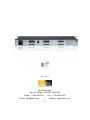
XTM-300 Bi-amp Crossover Instruction Manual 181 Bonetti Drive San Luis Obispo, CA 93401-7397 USA Phone: +1 805 549 0161 Fax: +1 805 549 0163 E-mail: [email protected] Website: www.uslinc.com One-Year Limited Warranty USL, Inc. warrants that each product manufactured by it will be free from defects in material and workmanship under normal usage for a period of one (1) year after its purchase new from an authorized dealer. Our obligation under this warranty is limited to repairing or replacing any product or component which we are satisfied does not conform to the foregoing warranty and which is returned to our factory, freight paid, or serviced by one of our authorized contractors. The foregoing warranty is exclusive and in lieu of all other warranties, whether expressed or implied. Such warranty shall not apply to any product or component (A) repaired or altered by anyone other than USL, Inc. or an authorized service contractor; (B) tampered with or altered in any way or subjected to misuse, negligence or accident or (C) which has been improperly connected installed or adjusted other than in accordance with USL, Inc.’s instruction. 2 Table Of Contents 1. Safety Notice 4 2. Regulatory Compliance 5 3. Introduction 7 4. Installation 9 5. Wiring Diagrams 10 6. Pinouts 12 7. Specifications 15 8. XTA-680EA Setup 16 9. XTD-680 Instructions 19 10. Revision History 26 3 1. Safety Notice Review the following safety precautions to avoid injury and prevent damage to this product. To avoid potential risk, use this product only as specified and only for the purpose described in the instruction manual. To Avoid Fire and Personal Injury: Use correct power cable. Use only the power cable provided. Ensure that the AC power outlet is located near the product and is easily accessible. Use a correctly grounded power source. The power supply earth ground is established through the ground conductor in the power cable. To avoid the potential of electric shock, the ground conductor must be correct. Observe source ratings. To avoid risk of fire or electric shock, the power source must be 100 – 240 VAC, 50 – 60 Hz. Do not operate with suspected failures. If you suspect there is damage or malfunction with this product, call the factory. Do not attempt repair. product. Do not operate this product near heat sources. This product should not be located near heat sources such as radiators, heat registers, or stoves. Provide proper ventilation. The operating temperature range is between 0º C and 40º C. The humidity range is between 20% and 80%, non-condensing. The cooling method is convection. Keep product surfaces clean and dry. Disconnect the power cable from the power source before cleaning. Do not use liquid cleaners or aerosol cleaners. Use a damp cloth for cleaning. Do not push objects into openings of this product. Never insert objects into the product through openings. Do not operate in wet or damp conditions. Do not operate in an explosive atmosphere. Inspect the power cable and all cables prior to use. Confirm that the power cable and other interconnecting cables are free from damage. Only a trained factory service person is authorized to repair this 4 2. Regulatory Compliance EN 60950-1 The EN 60950-1 standard specifies the safety design requirements that reduce or eliminate the risk of personal injury to both the product user and service personnel. This product is designed and tested to meet the standards of the International Electrotechnical Commission (IEC) European Norm EN 60950-1, IEC 60950-1 (the standard for information technology equipment including electrical business equipment). Declaration of Conformity The XTM-300 meets the intent of Directive 89/336/EEC for Electromagnetic Compatibility and Low Voltage Directive 73/23/EEC for Product Safety. Compliance was demonstrated to the following specifications as listed in the Official Journal of the European Communities: EN 55022: 2006 Conducted and Radiated Emissions Conducted Emissions Radiated Emissions, Class A Limits EN 55024: 1998 + A1: 2001 & A2: 2003 Immunity Electrostatic Discharge Immunity RF Electromagnetic Field Immunity Power Line Surge Immunity Conducted RF immunity Power Frequency Magnetic Field Susceptibility Voltage Dips, Short Interruptions and Variations EN 61000-3-3: 1995 +A1: 2001 & A2: 2005 Voltage Fluctuation and Flicker FCC Part 15, Subpart B This equipment has been tested and found to comply with the limits for a Class A digital device, pursuant to part 15 of the FCC Rules. These limits are designed to provide reasonable protection against harmful interference when the equipment is operated in a commercial environment. This equipment generates, uses, and can radiate radio frequency energy and, if not installed and used in accordance with the instruction manual, may cause harmful interference to radio communications. Operation of this equipment in a residential area is likely to cause harmful interference in which case the user will be required to correct the interference at user’s own expense. 5 Certifications Low Voltage Directive 73/23/EEC. EN 60950 Information Technology, Video, and similar Electronic Apparatus. IEC 60950 Safety Requirements. CE, UL, cUL Safety and Overall Compliance. VDE Certified Power Cords. Pollution: Not intended for environments where conductive pollutants may be present. Equipment Class Type A: Equipment that is intended for connection to the building power supply wiring via nonindustrial plugs and sockets or via appliance couplers, or both. Disposal and Recycling Wheelie-Bin Symbol The Wheelie-Bin symbol is attached to this product in compliance with the EU Directive 2002/96/EC on Waste Electrical and Electronic Equipment (WEEE). Its purpose is to deter the improper disposal of this product and to promote reuse and recycling. Proper Disposal In conformance with the Directive, at end of life this product should be either sent to an appropriate recycling facility for disassembly and recycling or returned to the supplier. Under no circumstances should this product be deposited in a landfill for disposal. Hazards of Noncompliance Electrical and electronic products may contain chemicals, which can leach into the groundwater and cause health concerns through contaminated drinking water. Failure to dispose of this product in compliance with the WEEE Directive may result in penalties as determined by local ordinance. Please contact your dealer or USL, Inc., with questions regarding the proper disposal of this or any other USL product. USL, Inc. contact information: USL, Inc., 181 Bonetti Drive, San Luis Obispo, CA 93401-7397, USA. Phone: +1 805-549-0161 Fax: +1 805 -549-0163 www.uslinc.com 6 3. Introduction Please read this entire manual before commencing your installation. The USL XTM series crossover module has been designed for high performance, ease of use, and years of trouble free service. No special tools are required. The components that make up the XTM are of computer grade for reliability. All USL equipment has been “burned-in” at the factory for an extended period in order to eliminate the possibility of premature failure. Unpack the unit carefully. If the container has been damaged, thoroughly inspect the equipment to make certain that there is no hidden damage. File a claim immediately with the carrier if any damage is found. Also advise your dealer or the factory. The USL XTM-300 is a bi-amp crossover chassis for use with the XTA-680EA analog crossover card or the XTD-680 digital crossover card, each of which provides three channels (left, center, right) of bi-amp configuration. The XTA card provides the low cost ability to set 11 distinct crossover frequencies and 4 low frequency time delays for the left, center and right channels. The optional XTD-680 digital crossover card provides increased flexibility for setting the left, center, right and LFE channels including parametric, screen and horn EQs, gains and delays . The card is configured with an easy to use graphical user interface that runs on a laptop computer communicating via a USB cable. A library of existing speaker types is provided, or each of the features may be configured manually. NOTE: Although the XTD card is capable of supporting tri-amp configurations, the XTM-300 does not support tri-amp use. Should you need tri-amp support, please contact USL. You will need to supply the following materials and tools: One DB25 cable (female to female) for connecting the XTM to the cinema processor (USL JSD -60). Two DB25 cables (female to male) for connecting the XTM to the monitor (USL CM-8E). Optional Phoenix connectors allow connection to amplifiers or other equipment. Four 10-32 x 1/2" (or M6) screws to mount the XTM-300 in the audio equipment rack. Screwdriver for the rack mounting screws above. Wire strippers (if the terminal blocks will be used). Small Phillips screwdriver (to remove the cover plate). Trimpot adjustment tool or small flat blade screwdriver (to adjust bypass levels). 7 Features The XTM-300 Series Crossover Module has the following standard features: Designed to split the signals of the left, center and right channels for use with bi-amplified sound systems. Analog or digital crossover card for processing the left, center and right channels. Provides input point for a spare channel that can be monitored using the USL CM-8E monitor. Provides an emergency bypass crossover should the main power supply fail. 1. Crossover card access cover. 2. Crossover bypass switch - When in bypass, the active crossover is replaced with a passive crossover for emergency use. 3. Power Supply Voltages Status LEDs 4. Power Switch 1. Main AC connector with fuse. 2. Crossover output to monitor - L, C, R high bands and spare. (DB25 male) 3. Crossover output to monitor/amplifier - L, C, R high bands and spare input. 4. DC emergency power input - 12VDC, 1A 5. Crossover output to monitor - L, C, R low bands, Ls/Rs, Lrs/Rrs, LFE. (DB25 male) 6. Crossover output to monitor/amplifier - L, C, R low bands and LFE. 7. Main input - connect this to the main output of the processor. (DB25 female) 8. Surround outputs to monitor/amplifier - Ls/Rs, Lrs/Rrs. 8 4. Installation The ideal place for the XTM-300 is in the sound rack or projector console between the audio processor and monitor or power amplifiers. Crossover Wiring 1. Power: Connect the unit to the AC power outlet using the standard IEC cable provided. Any power source from 100-250VAC, 50-60 Hz will be sufficient. 2. Bypass power: Connect the unit to the AC power outlet using the supplied modular power supply. Any power source from 100-250VAC, 50-60 Hz may be used by changing the AC pin adapters. 3. XTM input from processor outputs: Use the male-female 25 pin D cable to connect the output of the cinema processor to the main input of the XTM. 4. Crossover outputs to monitor inputs: Use the male-female 25 pin D cables to connect the output of the XTM to the main and option inputs of a CM series monitor (CM-8E recommended). Note that the CM-8E provides a spare input which may be routed through the XTM’s high band terminal block. 5. Terminal blocks are also provided to allow wiring to other monitors that have differing pinouts. All crossover outputs are balanced. Use two conductor shielded cable to minimize ground loops and hum. 6. Crossover outputs to power amplifier inputs: Use the terminal blocks provided to wire to traditional amplifiers directly. All crossover outputs are balanced. Use two conductor shielded cable to minimize ground loops and hum. Connect each of the crossover channel outputs to the appropriate amplifier input. 7. DB25 connectors are available on the back plane to make installation quick and easy. Alternatively, terminal blocks allow the use of stripped and tinned wire. They are pluggable for easy service and troubleshooting. 9 5. Wiring Diagrams MALE MALE MALE FEMALE FEMALE FEMALE 10 MALE MALE MALE FEMALE LFE 11 6. Pinouts Input DB25 Female Pin Function Pin Function 1 Earth 14 L- 2 L+ 15 Earth 3 Lrs- 16 Lrs+ 4 Earth 17 C- 5 C+ 18 Earth 6 Rrs- 19 Rrs+ 7 Earth 20 R- 8 R+ 21 Not Connected 9 Earth 22 Earth 10 Ls- 23 Ls+ 11 Rs- 24 Rs+ 12 LFE- 25 LFE+ 13 Earth 12 Output Lows & Surrounds DB25 Male Pin Function Pin Function 1 Earth 14 Ll- 2 Ll+ 15 Earth 3 Lrs- 16 Lrs+ 4 Earth 17 Cl- 5 Cl+ 18 Earth 6 Rrs- 19 Rrs+ 7 Earth 20 Rl- 8 Rl+ 21 NC 9 Earth 22 Earth 10 Ls- 23 Ls+ 11 Rs- 24 Rs+ 12 LFE- 25 LFE+ 13 Earth Output Highs DB25 Male Pin Function Pin Function 1 Earth 14 Lh- 2 Lh+ 15 Earth 3 NC 16 NC 4 Earth 17 Ch- 5 Ch+ 18 Earth 6 NC 19 NC 7 Earth 20 Rh- 8 Rh+ 21 NC 9 Earth 22 Earth 10 NC 23 NC 11 NC 24 NC 12 Spare- 25 Spare+ 13 Earth 13 Phoenix Outputs (Parallel the DB25s) Pin Lows Highs Surrounds 1 Ll+ Lh+ Ls+ 2 Ll- Lh- Ls- 3 Earth Earth Earth 4 Cl+ Ch+ Rs+ 5 Cl- Ch- Rs- 6 Rl+ Rh+ Lrs+ 7 Rl- Rh- Lrs- 8 Earth Earth Earth 9 LFE+ Spare Input+* Rrs+ 10 LFE- Spare Input-* Rrs- * Note: The spare input connects directly to the high band DB25 output to drive the CM-8E 14 7. Specifications Inputs Eight inputs via a DB25 (female) corresponding to left, center, right, left surround, right surround, left rear surround, right rear surround, and subwoofer (LFE). Input impedance is 10k . Spare channel feeds through unit from high band terminal block to the DB25 connector for use with the CM-8E monitor. Outputs Two DB25M connectors. One connector provides the passed through audio for the surround and LFE channels. It also provides the low band crossover outputs for the left, center, and right channels. The second DB25 connector provides the high band crossover outputs for the left, center, and right channels. This connector also passes through the spare channel to drive the CM-8E monitor. Three terminal blocks are wired in parallel with the DB25s to accommodate other equipment. Controls Main power switch. LED indicators illuminate when the main power supply is active. The backup power LED indicates that the bypass power supply is active, even when the Main Power switch is off. Normal/bypass LEDs indicate which circuitry is selected. Both work when the main power supply is active. Should the main power switch be turned off, the bypass switch must be manually set to bypass. Power Requirements 100-240VAC, 50-60Hz, 32 Watts Construction The XTM is constructed of steel to minimize hum pickup and noise radiation. The overall size of the unit is 1.75" x 19" x 10.5" (44mm x 483mm x 267mm). The XTM is designed to mount in a standard rack frame or cabinet. Weight: 7 lbs. (3.1 kg) Shipping weight: 12 lbs. (5.4kg) Shipping Size: 22” x 22” x 6” (558.8 x 558.8 x 152.4 mm) 15 8. XTA-680EA Setup XTA-680EA Analog Crossover Setup The following parameters must be set: crossover frequency, time delay, horn EQ, screen EQ, output levels, and bypass levels. Make sure the NORMAL/BYPASS switch is in the NORMAL position. Determine the crossover frequency and time delay for the speaker system being used. Some common types are listed below. Crossover Frequencies & Delay Chart for common Bi-amp Speakers SPEAKER DEFAULT Bi-amp EAW CB152 EAW CB153 EAW CB259 EAW CB2591 EAW CB423MX EAW CB523MX EAW MC4953B EAW MC4973B EV TS550D-LX EV TS550DMTLX EV TS9040D-LX EV TS940D-LX EV TS-940S EV TS992-LX EV TS993C EV VARIPLEX-B JBL 3115 JBL 3632 JBL 3678 JBL 4622 JBL 4632 JBL 4670 D JBL 4675C 4LF XO (Hz) DELAY (ms) 800 1200 400 620 500 400 400 300 300 500 500 500 650 800 1160 380 340 340 460 1000 640 300 800 500 0 0 0 0.6 1.1 0.1 0.1 0.1 0.1 1.7 1.7 1.7 0.7 0.7 0 0 1.4 0.4 1 0 1 1 0.7 1.9 16 Crossover Frequencies & Delay Chart for common Bi-amp Speakers (Continued) SPEAKER XO (Hz) DELAY (ms) KCS S-2001 D 800 0 KCS S-2001 800 0 KCS S-2501 800 0 KCS S-3001 500 1.8 KCS S-5001 500 1.8 KLIPSCH KPT-325 800 0 KLIPSCH KPT-535-N 500 0.7 KLIPSCH KPT-904-T 800 0 KLIPSCH KPT-941-T 500 1.2 KLIPSCH KPT-942 500 0.7 MARTIN SCREEN2 1100 0 MARTIN SCREEN4 640 0 SA S 26 1400 0 SA S 27 1300 0 WSS 952 800 0.7 WSS 953 X2 500 1.8 WSS 953 500 1.8 WSS 971 1000 0 WSS 982 D 400 0.7 17 Set the crossover frequency and time delay by setting the dipswitches for each channel to achieve the closest match to the desired value. XTA-680EA Frequency Chart Frequency (Hz) Sw A Sw B Sw C Sw D 300 350 On 400 On 460 On On 500 On 600 640 On On On On On 800 On 1000 1100 1200 On On On On On On On On On XTA-680EA Time Delay Chart Time (ms) Sw X Sw Y 0.7 1.0 On 1.4 1.8 On On On 18 Screen and Horn EQs: Generally, all six dipswitches should be “On”. In some cinemas, the left and right speakers are mounted outside the screen area. In this case, turn the left and right screen EQ switches to “Off”. Some high frequency horns are very flat to 20kHz. In this case, you may want to turn the horn EQ switches to “Off”. The screen and horn equalizers each add a shelving high pass filter boosting 7kHz by 5dB and 20kHz by 8dB. The combination of horn and screen EQ results in about 16dB boost at 20kHz. Using a Real Time Analyzer and feeding a pink noise signal from the cinema processor, set the appropriate trimpots for a flat response around the crossover frequency and a total SPL level of 85dB on each of the front three channels. There should be enough range in the output pots to allow setting the amplifier gains between 50 to 100% of maximum. Set the NORMAL/BYPASS switch to BYPASS. The Bypass Crossover is fixed at about 430Hz with no time delay. It combines the left, center and right signals and then feeds the center output only. Using a Real Time Analyzer and feeding pink noise from the center channel of the cinema processor, set the bypass levels for flat response around 400 to 500Hz and SPL level of 85dB. Return the BYPASS/NORMAL switch to NORMAL. 9. XTD-680 Setup Digital Crossover Module Instructions The USL XTD-680 is a digital crossover card for use in the XTM-300. When used in the XTM300, the XTD-680 provides bi-amp crossovers for the left, center, and right channels. It also provides gain and delay controls for the LFE channel. The card is configured using a graphical user interface running on a laptop computer. The computer communicates with the XTD-680 over USB. A library of standard cinema speakers is provided. In addition, specific crossover characteristics can be set manually. The XTD-680 also includes a passive bypass crossover for emergency use. 19 XTD-680 Controls, Indicators, Connectors 20 Software Installation Place the installation CD into the CD drive. The XTD-680 Setup Screen will appear To continue with the installation, choose “Next >”. If this is the first time setting up and installing an XTD-680, it is recommended that the precaution be taken of turning down the gain of the stage speaker amplifiers to a low level and turning OFF the amplifiers for the surrounds and subwoofer. The opening installation screen appears. 21 XTD-680 Crossover Setup Connect to the XTD-680 using the connect icon. Upon connection to the XTD-680,the window at the bottom right of the main screen changes from to If the mode is set to triamp, press biamp since the XTM-300 only supports biamp. A warning about selecting an appropriate speaker from the library will appear. Clicking on the “Default Biamp” button will bring up a Speaker Library. 22 In the speaker library window, use the dropdown menu to select a particular speaker from the speaker library. You may load channels by checking the boxes in the library window. When you have selected the channels you want, click “OK” to close the “Speaker Library” window. At this time, the settings you selected are loaded into the XTD-680 and will be reflected in the display and the data at the bottom of the display. You may un-mute the system and audio should be present. This would be a good time to do a Disconnect and select “Save”. After doing a Disconnect/ Save, the XTM-300 should be power cycled. When the unit comes back on, it should be ready for use with the speaker crossover settings you saved. Bypass Crossover DIP Switch Setting Bypass Crossover Dipswitch Setting 1 2 3 4 5 6 BIAMP 300 Hz OFF ON OFF ON OFF ON BIAMP 1khz OFF OFF ON OFF ON ON . 23 XTD-680 Specifications Input/Output Channels: Balanced line Inputs: 15K, 0dB=300mVrms, Balanced line Outputs: <1k, 0dB=300mVrms Left, Center, and right Channels: Triamp or Biamp operation. (Biamp only in XTM-300) LFE channel: single range operation. Analog Input reference level: 300mVrms-0dBr. Digital Input reference level: -26dBFS. Input Level Indicator LED: >-30dBr (-56dBFS). Note: Flat Input EQ, Tone at 1kHz except LFE at 100Hz May not provide accurate reading with equalized processor settings and/or pink noise. All Frequency increments are 1Hz. All Gain increments are 0.5dB. All Q increments are 0.25. All Delay increments are 20.8us. Features/Functions: All Channels: Global Mute Channel Delay: 0 to 10 ms Channel Level: -22 to +8dB Left, Center, Right Channels: Channel High Pass: Frequency Range: 20 to 40 Hz Q: 0.707 or 2.0 High Band High Pass Filter (Lindquist-Riley): 200 to 4 kHz Band Gain: -18 to 0dB Band Delay: 0 to 5304us Parametric: Frequency: 300 to 20 kHz Gain: -12 to +6dB Q: 0.5 to 10 Horn Filter: Frequency: 1 k to 15 kHz Gain 0 to +6dB Screen Filter: Frequency: 1 k to 15 kHz Gain: 0 to +6dB Band Mute Invert 24 Low Band Low Pass Filter (Lindquist-Riley): 100 to 4kHz Band Gain: -18 to 0dB Band Delay: 0 to 5304us Parametric: Frequency: 25 to 4 kHz Gain: -12 to +6dB Q: 0.5 to 10 Band Mute Invert LFE Channel Low Pass Filter (12dB/Oct): 500Hz, fixed. Band Gain: -18 to 0dB Band Delay: 0 to 5304us Band Mute Invert 25 10. Revision History V140131 Draft V140205 Add connection genders, formatting. V140228 Minor edits. V140407 Added XTA information, front and rear photos V140410 Added Section 9. XTD-680 Instructions V140414 Updated pictures, edit text throughout 26 27 Version 140414 181 Bonetti Drive San Luis Obispo, CA 93401-7397 USA Phone: +1 805 549 0161 Fax: +1 805 549 0163 E-mail: [email protected] Website: www.uslinc.com 28