1
K2200 Series
Installation Guide
EN
Readykey Controllers
K2200 Series | Installation Guide | Contents
Contents
1.0
1.1
1.2
1.3
1.3.1
1.3.2
1.4
1.5
1.5.1
1.5.2
1.5.3
1.5.4
2.0
2.1
2.1.1
2.1.2
2.2
2.2.1
2.2.2
2.2.3
2.2.4
2.2.5
2.2.6
2.3
2.3.1
2.3.2
2.3.3
2.3.4
2.3.5
2.3.6
2.3.7
2.3.8
2.3.9
2.3.10
2.3.11
2.3.12
2.3.13
2.3.14
2.3.15
2.3.16
2.3.17
2.3.18
2.4
2.4.1
2.4.2
2.4.3
Introduction................................................... 4
Manual Organization ..................................... 4
Other Literature Referenced ......................... 4
Documentation Conventions ........................ 4
Type Styles Used in this Manual .................. 4
Tips, Important Notes, Cautions and
Warnings.......................................................... 4
Abbreviations Used........................................ 5
Listings and Approval .................................... 6
FCC Notice ..................................................... 6
UL Listing........................................................ 6
HEALTH AND SAFETY ............................. 6
CABLING ....................................................... 6
K2200 Series Controllers............................ 7
What is the Readykey K2200 Series of
Controllers? ..................................................... 7
Introduction..................................................... 7
Controllers in the Series ................................ 7
Multi-Function Door Controller ................... 7
Background ..................................................... 7
Components .................................................... 9
Readers ............................................................ 9
Door Controllers............................................. 9
Connecting Door Controllers ..................... 10
Compatibility ................................................ 10
Features.......................................................... 11
Summary of Features ................................... 11
Appearance ................................................... 11
Faceplate........................................................ 12
Software Version and Model Type ............ 12
Power Supply Unit ....................................... 12
Memory Module........................................... 12
Memory Backup Battery.............................. 13
On- Board Relays........................................ 13
Alarm Event Managers ................................ 13
Dial-Back Facility.......................................... 13
Protected Communications ......................... 13
Remote Acknowledgement ......................... 13
Transaction Filtering .................................... 13
Multiple Reader Formats............................. 14
Anti-Passback ................................................ 14
Master Override Input................................. 15
Download Times .......................................... 15
Compatibility with Previous Models.......... 15
Specifications................................................. 16
Environmental .............................................. 16
Power Supply ................................................ 16
Cable .............................................................. 16
Bosch Security Systems | 7/03 | 17375 1.3 / 46513C
EN | 2
3.0
3.1
3.2
4.0
4.1
4.2
5.0
5.1
5.1.1
5.2
5.3
5.3.1
5.3.2
5.3.3
5.3.4
5.3.5
5.3.6
5.4
5.4.1
5.4.2
5.4.3
5.4.4
5.4.5
5.4.6
5.4.7
5.4.8
5.5
5.5.1
5.5.2
5.5.3
5.5.4
5.5.5
5.5.6
6.0
6.1
6.1.1
6.1.2
6.1.3
6.1.4
6.1.5
6.1.6
6.1.7
6.1.8
6.1.9
6.1.10
6.2
6.2.1
6.2.2
Administration Systems............................ 17
Introduction .................................................. 17
Faceplate Administration – 16-door........... 17
Six-Wire Bus................................................ 19
Cable Specification....................................... 19
Addresses....................................................... 20
Installation Details..................................... 21
Readykey K2200 Series Controllers Description .................................................... 21
Multi-Function Door Controllers (K2200 and
K1200) ........................................................... 21
Introduction .................................................. 23
Installing the Controller............................... 23
Metal Case..................................................... 24
Faceplate........................................................ 25
Fitting Direct to a Flat Surface .................... 25
Power Supply ................................................ 26
Lock Output Voltage ................................... 26
Battery Backup.............................................. 27
Installing Readers and Locks ...................... 30
KeyPAC K3000 Series Readers.................. 30
K2000 Series Readers .................................. 30
Request to Exit (DR2).................................. 34
Door Monitoring (DR1)............................... 34
Emergency Override/Free Exit .................. 35
Lock Output.................................................. 36
Lock Sharing ................................................. 36
PIN Reader ................................................... 37
Other Connections ....................................... 37
Relay Outputs ............................................... 37
Case Tamper Input ...................................... 37
Override Input.............................................. 38
Alarm Event Manager ................................. 39
26-bit Wiegand Readers .............................. 39
Magstripe Readers........................................ 39
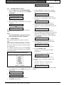
Configuration and Testing....................... 41
Powering Up – First Checks ....................... 41
Programming Mode ..................................... 41
INIT Command............................................ 41
K Command ................................................. 41
SYSTEM START Command ..................... 42
INST Command........................................... 42
Test Mode ..................................................... 44
Setting the Modem Connection.................. 45
Event Mode................................................... 46
Programming Readers and Locks (For
Standalone Masters only, no software) ...... 47
Testing Readers and Locks ......................... 50
RS-232 Serial Port ........................................ 50
Connecting a Printer .................................... 50
PC Interface Kit............................................ 51
K2200 Series | Installation Guide | Contents
6.2.3
7.0
7.1
7.1.1
7.1.2
Connecting a Modem .................................. 52
Troubleshooting ......................................... 53
Door Controllers and Readers.................... 53
The controller appears to be dead.............. 53
One or more readers or locks fail to operate
........................................................................ 53
7.1.3
Checking the Reader.................................... 53
7.1.4
Checking the Lock Output.......................... 54
7.1.5
No error is displayed on the master but the
slave still fails to communicate.................... 54
8.0
Transactions ................................................ 55
8.1
High Priority Transactions .......................... 55
8.2
Dial Back Transactions ................................ 55
8.3
‘Forget’ Transactions .................................... 55
8.3.1
Request to Exit.............................................. 55
8.3.2
Positive Transactions.................................... 56
8.3.3
Negative Transactions.................................. 56
Index 57
Figures
Figure 1: Failsafe Lock Wiring................................... 6
Figure 2: Components of a Readykey Access
Control System............................................ 8
Figure 3: Readykey K2200 System Configuration .. 8
Figure 4: Software Version and Model Type Display
..................................................................... 12
Figure 6: Possible Reader Locations for Local AntiPassback ..................................................... 14
Figure 7: System Diagram – Faceplate
Administration........................................... 17
Figure 10: Six Wire Bus Wiring Configuration........ 19
Figure 11: Six-Wire Bus Wiring................................. 20
Figure 12: Readykey K2200 Door Controller with
Faceplate Fitted ......................................... 21
Figure 13: Readykey K2200 Door Controller with
Faceplate Removed .................................. 22
Figure 14: Recommended Wiring Layout................ 24
Figure 15: Metal Case ................................................. 25
Figure 16: Rear View of Door Controller Base Plate
..................................................................... 26
Figure 17: Continuous Current Estimation Equation
..................................................................... 27
Figure 18: Using an External Battery Charger......... 29
Figure 19: Reader Wiring Diagram - Terminals...... 31
Figure 20: Reader Wiring Diagram - Flying Lead... 31
Figure 21: Reader Wiring Diagram - In/Out Readers
..................................................................... 32
Figure 22: Request to Exit Wiring Diagram............. 34
Figure 23: Wiring for Door Monitoring.................... 34
Figure 24: Emergency Override / Free Exit Wiring35
Figure 25: Lock Output Wiring ................................. 36
Figure 26: Relay Outputs............................................ 37
Bosch Security Systems | 7/03 | 17375 1.3 / 46513C
EN | 3
Figure 27: Case Tamper Wiring ................................ 38
Figure 28: Override Input Wiring ............................. 38
Figure 29: AEM Cable Distances .............................. 39
Figure 30: Magstripe Connection.............................. 40
Figure 31: Master Controller DIP Switches ............. 42
Figure 32: Slave Controller DIP Switches ................ 43
Figure 33: Master Controller (with Admin Kit and
software) DIP Switches............................. 43
Figure 34: Printer Cable Pin-outs .............................. 51
Figure 35: Line Driver Wiring Diagram................... 52
Figure 36: Modem to Readykey K2200 Series Cable
.................................................................... 52
Tables
Table 1: K2200 Series Installation Guide
Organization................................................ 4
Table 2: Other Literature Referenced ..................... 4
Table 3: Type Styles Used in Manual ..................... 4
Table 4: Compatible software version numbers... 10
Table 5: Summary of Features................................ 11
Table 6: Environmental Specifications................. 16
Table 7: Power Supply Specifications................... 16
Table 8: Cable Specifications ................................ 16
Table 9: See these Documents – Faceplate
Administration – 16-door......................... 17
Table 10: 16-Door Limits......................................... 17
Table 11: Continuous Lock Supply Current........... 27
Table 12: Total Reader Channel Current ............... 28
Table 13: Determining Total Power ........................ 28
Table 14: Appropriate Wire Gauge based on Length
.................................................................... 32
Table 15: Readers with Terminals ........................... 33
Table 16: Readers with Flying Leads....................... 33
Table 17: Reader Channel Lock Sharing ................ 37
Table 18: Relay Responses ....................................... 37
Table 19: Input Physical State Codes ...................... 44
Table 20: Display Status ............................................ 44
Table 21: Setup Options............................................ 45
Table 22: Key Combinations to obtain keys not on
keypad........................................................ 46
Table 23: Lock Mode Settings .................................. 48
Table 24: Lock Mode 2 Settings............................... 49
Table 25: High Priority Transactions....................... 55
Table 26: Dial Back Transactions............................. 55
K2200 Series | Installation Guide | 1.0 Introduction
EN | 4
1.3
1.0 Introduction
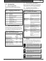
1.1
Manual Organization
This document is divided into nine sections. A
summary of each section is detailed in the table
below.
Table 1: K2200 Series Installation Guide
Organization
Section
1
2
3
4
5
6
7
8
9
Documentation Conventions
These conventions are intended to call out important
features, items, notes, cautions, and warnings that the
reader should be aware of in reading this document.
1.3.1
Type Styles Used in this Manual
To help identify important items in the text, the
following type styles are used:
Table 3: Type Styles Used in Manual
Bold Text
Description
Introduction
K2200 Series Controllers
Administration Systems
Six-Wire Bus
Installation Guide
Configuration and Testing
Troubleshooting
Faceplate Administration
Transactions
Bold Italicized
Text
Italicized Text
Courier Text
1.2
Other Literature Referenced
Throughout this manual, references will be made to
other documentation. See the following table for a
more complete and detailed description of the K2200
Series Controllers, which lists the complete part
number for ordering purposes.
[CAPITALIZED
TEXT]
On-Screen
Buttons
File New
Table 2: Other Literature Referenced
Name of Document
Readykey for Windows
System Overview
Readykey for Windows
System Programming Manual
Readykey K2200 Series
Controllers User’s Guide
Readykey Central Network
Controller Installation Guide
Part Number
Bosch/
PAC
Radionics
43484
17149
44611
17244
47491
17376
46512
17163
1.3.2
Usually indicates selections that
you may use while programming
your panel. May also indicate an
important fact that you should
note.
Denotes notes, cautions and/or
warnings.
Refers you to a drawing, table, or
other section of this document, or
to another document. Also used to
symbolize names for records that
you will create.
Indicates what may appear on the
command center/keypad, or
internal printer.
Indicates a specific key on the
device to be pressed.
Indicates a specific button that
appears on screen
This is used to describe the path in
getting to a specific sub-menu or
command in a Windows-based
application.
Example: …select File•New to
create a new
Tips, Important Notes, Cautions and
Warnings
Throughout this document, helpful tips, important
notes, cautions and warnings will be presented for the
reader to keep in mind. These appear different from
the rest of the text as follows;
Important Notes - should be heeded for
successful operation and programming.
Also tips and shortcuts may be included
here.
Caution - These caution the operator that
physical damage to the program and/or
equipment may occur.
Warning - These warn of the possibility of
physical damage to the operator, program
and/or equipment.
Bosch Security Systems | 7/03 | 17375 1.3 / 46513C
K2200 Series | Installation Guide | 1.0 Introduction
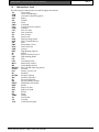
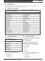
1.4
Abbreviations Used
The following list of abbreviations are used throughout this manual.
Access Code
AC
Alarm Event Manager
AEM
Automatic Vehicle Recognition
AVR
Battery
BAT
Channel
CH
Clock
CLK
Command
CMD
Central Network Controller
CNC
Common
COM
Clear To Send
CTS
Door Controller
D/C
Door Contact
DC
Down Load
DL
Disk Operating System
DOS
Delay Transmit/Receive
DTR
Door
DR
Electro-Motive Force
EMF
First In First Out
FIFO
Ground
GND
High Breaking Capacity
HBC
Identity
ID
Input or Internet Protocol
IP
Light Emitting Diode
LED
Lock
LK
Lock Release Time
LRT
Metal Oxide Varistor
MOV
Alarm Module Sensors
MS
Microsoft Disk Operating System
MS-DOS
Override
OVRD
Primary Access Level
PAL
Pass Back
PB
Pass Back Timeout
PB-TIM
Pass Back Controller
PBC
Personnel Computer
PC
Personal Identity Number
PIN
PIN Reader Time Profile
PINTP
Reader
RDR
Request To Exit
RTE
Request To Send
RTS
Receive
RX
Signal
SIG
Tamper
TAMP
Time Profile
TP
Transmit
TX
Valid Code Accepted
VCA
Bosch Security Systems | 7/03 | 17375 1.3 / 46513C
EN | 5
K2200 Series | Installation Guide | 1.0 Introduction
1.5
Listings and Approval
1.5.1
FCC Notice
This equipment generates and uses radio frequency
energy. If not installed and used in accordance with
the manufacturer's instructions, it may cause
interference to radio and television reception. It has
been tested and found to comply with the
specifications Subpart F of Part 15 of FCC rules for
Field Disturbance Sensors. If this equipment causes
interference to radio or television reception - which
can be determined by turning the equipment on and
off - the installer is encouraged to correct the
interference by one or more of the following
measures:
1. Reorient the antenna of the radio/television,
2. Connect the AC power cord to a different outlet
so the control panel and radio/television are on
different branch circuits,
3. Relocate the control panel with respect to the
radio/television.
If necessary, the installer should consult an
experienced radio/television technician for additional
suggestions, or send for the "Interference Handbook"
prepared by the Federal Communications
Commission. This booklet is available from the
U.S. Government Printing Office,
Washington D.C. 20402,
stock no. 004-000-00450-7.
FCC Registration Number: IDHM32Y6K2000
1.5.2
UL Listing
UL 294 -
Access Control System Units
When installing the K2200 series
controllers the following should be noted:
1.5.3
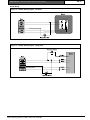
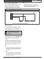
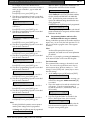
HEALTH AND SAFETY
It must also comply with any local Fire, Health and
Safety regulations. A secured door that may be part
of an escape route from an area must be installed
with:
•
A fail-safe lock (A). So that the door will
be released if the power fails. Ideally a
magnetic lock should be used as these
are less likely to jam or seize.
•
A normally-closed break-glass or manual
pull (B) in the lock supply wiring. So that
in an emergency the fail-safe lock can be
immediately powered down.
Bosch Security Systems | 7/03 | 17375 1.3 / 46513C
EN | 6
Figure 1:
Failsafe Lock Wiring
B
A
The controller must be grounded.
Disconnect both ac and battery power supply before
working on the controller.
1.5.4
CABLING
The cabling used in the Readykey access control
systems (six wire bus, reader cables, etc.) are not
prone to electrical interference. However, you should
avoid routing cable close to heavy load switching
cables and equipment. If this is unavoidable, cross
the cable at right angles every 3.3 to 6.6 ft (1 to 2 m)
to reduce the interference.
K2200 Series | Installation Guide | 2.0 K2200 Series Controllers
2.0 K2200 Series Controllers
This section provides a brief introduction to the
Readykey K2200 Series Controllers. In it, the user is
shown:
•
The different controllers in the series and what
each does.
•
Compatibility with older Readykey products.
•
What features are provided on each controller.
Please read this document even if you are
familiar with previous Readykey products.
There is a great deal of new information
contained in this document that should
make installation and testing a lot easier.
You are also advised to attend a
Readykey Training Course before
attempting installation
2.1
What is the Readykey K2200 Series
of Controllers?
2.1.1
Introduction
The Readykey K2200 Series Controllers are the
successors to the Readykey K2100 Series Controllers.
Although all the controllers can operate in standalone
mode they are primarily designed to be a part of a
larger system administered by Readykey for
Windows. This provides easy access to all the new
features with configuration carried out mainly at the
administration PC.
The controllers will form part of a Readykey Access
Control System and it is important that, when
installing these controllers, you are aware of the
whole system and how it is to be administered.
2.1.2
2.2
Multi-Function Door Controller
2.2.1
Background
Most Readykey access control systems, very simply,
consist of eight distinct parts:
1. The ID Device is presented to (or swiped
through) the reader to open a door. This has a
unique code which identifies it to the system.
2. The Reader, usually fitted close to the door,
detects the unique code in the ID device and
sends it to the door controller for verification.
There are several types of reader available,
suitable for different purposes and environments.
It is usually situated close to the door.
3. The Request to Exit (RTE) Switch is used to
open a door from the secure side (sometimes a
reader is used on each side of the door). When
the switch is pressed a signal is sent to the
controller to release the lock and open the door.
4. The Controller is the heart of the access control
system. It compares the unique code in the ID
Device with the information stored in its memory
and, if the ID Device is valid, it activates the lock
to open the door.
5. The PSU(s) powers the controller and locks.
6. The Lock secures the door and is released when
a valid ID Device is presented to the reader.
Locks can be divided into two main types:
•
7.
Controllers in the Series
There are two main variants of the Readykey K2200
series. These are described in detail later in this
section but briefly they are:
1. Readykey K2200 Multi-Function Door
Controller. This is a replacement for the
Readykey K2100 with support for four alarm
event managers and four doors. It is available
with or without a faceplate.
2. Readykey K1200 Multi-Function Door
Controller. This is a replacement for the
Readykey K1100 with support for two alarm
event managers and two doors. It is available
with or without a faceplate.
Bosch Security Systems | 7/03 | 17375 1.3 / 46513C
EN | 7
8.
Fail Safe - continuously powered with power
removed to unlock. If power fails the door
will open.
• Fail Secure - Power supplied to unlock.
The Administration System is used to administer
the system - program into the system who goes
where and when. This may be built into the
controller or be on a separate PC.
The wiring between the various components
(above 1-7).
K2200 Series | Installation Guide | 2.0 K2200 Series Controllers
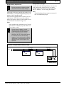
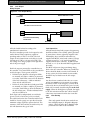
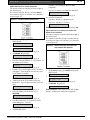
Figure 2:
EN | 8
Components of a Readykey Access Control System
Lock
Operate Lock >
Access Decision ?
Administration System
< Key Code
PSU
Reader
ID device
Door Controller
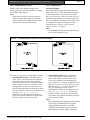
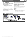
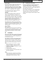
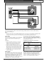
The Readykey K2200 Series Controllers (K2200 and K1200) are multi-function, i.e. they can be configured to
operate in a variety of different modes, depending on the overall system. Some features of the access control
system are dependent on the type of administration system used with some features (such as visitors, global
anti-passback, transaction searching and reporting) are only available on the PC-based administration systems.
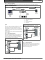
The following diagram shows the typical connections made to the door controller. For full details of how door
controllers are connected and administered, see Section 3.0.
Figure 3:
Readykey K2200 System Configuration
Bosch Security Systems | 7/03 | 17375 1.3 / 46513C
K2200 Series | Installation Guide | 2.0 K2200 Series Controllers
Before installing the door controller, you should be
aware of how it is going to be administered. The
controller can operate in one of two ways, either as a
master or as a slave providing the following
administration options:
Operating as a master, the door controller can be
administered:
•
From the door controller's own faceplate,
controlling up to 16 doors , 4 on board plus up
to 3 slave door controllers.
•
From a PC running Readykey for Windows
administration software via a PC interface kit.
This can control up to 32 doors - 1 master door
controller plus up to 7 slave door controllers
(Readykey for Windows is supplied with
different door license configurations).
•
From a PC running Readykey for Windows
administration software via a Readykey Central
Network Controller (CNC) using a RS-232 serial
link, can control up to 32 doors - 8 slave door
controllers. This can also accommodate up to
128 (dial-up) remote sites.
Operating as a slave, the door controller can be
administered:
•
From another Readykey K2200 Series Controller
configured as a master.
•
From a PC running Readykey for Windows
administration software via a Readykey Central
Network Controller (CNC) or an PC
Administration Kit.
2.2.2
Components
The door controller itself is made up of 4 individual
components:
Secured to the metal base plate are the 110/240 V
power supply and main circuit board. Fitted to the
main circuit board is a secondary “cover” board
which protects the main board and has a label which
identifies the various connectors on the main board.
Attached to this is the memory module containing
the software and database memory. Across the whole
unit is a removable faceplate with built-in key
reader, keypad and display.
2.2.3
All controllers are available without a faceplate.
However, at least one faceplate is required to configure
the controllers in the system.
Bosch Security Systems | 7/03 | 17375 1.3 / 46513C
Readers
A reader is a device, usually installed close to the
door, that detects the unique code in a key and
passes it to the door controller where the access
decision is made. There are several types of reader
suitable for different purposes and environments.
Note:
You can have two Readykey readers on the one reader
channel, i.e. an in and out reader. However, if the
reader output is in a Wiegand or Magstripe format, you
can only have one reader on each reader channel.
Readykey Low Profile Reader
A reader suitable for interior or exterior use.
Readykey Vandal Resistant Reader
A stainless steel or brass reader particularly suitable
for exterior use, where resistance to abuse is
important.
Readykey Panel Mount Reader
A reader designed for mounting in a steel panel, such
as a door entry system.
Readykey PIN Reader
This device requires a PIN number to be entered as
well as a key to be presented, as an extra level of
security. The need to use a PIN as well as a key can
be controlled using a time profile.
Readykey Slimline Reader
This device is a slimline version of the standard plus
reader, suitable for mounting on door frames, etc.
Magstripe Reader
This device converts the code in the magnetic stripe
to a format recognizable by the door controller. The
door controller supports Magstripe cards which are
encoded according to ISO 3554, Track 2.
Note:
Only one Magstripe reader can be
connected to each channel.
Wiegand Reader
The door controller supports most standard 26-bit
Wiegand formats
Note:
Only one Wiegand reader can be connected to each
channel.
All connections are made to the door controller using
removable terminal blocks.
Note:
EN | 9
2.2.4
Door Controllers
The door controller is the heart of the access control
system and it:
•
Decides whether a person has access at a
particular door and at a particular time.
•
Provides power to operate the lock.
•
Monitors doors for unauthorized access or door
left open.
K2200 Series | Installation Guide | 2.0 K2200 Series Controllers
•
Automatically opens and closes doors at certain
times.
•
Detects tamper conditions at the reader or its
own case.
•
Controls the 8 on-board relays.
•
Programs and monitors any Alarm Event
Modules (AEMs) that may be fitted.
2.2.5
Connecting Door Controllers
What makes the door controllers so flexible is the
ability to link controllers together to allow more
doors to be administered. The number of doors that
can be administered and the maximum number of
personnel that can be controlled, depends on the
type of administration system, see Section 3.0
Administration Systems.
Door controllers are connected together using
Readykey's six-wire bus. This is a proprietary
communications link that uses standard six-conductor
signal or alarm cable. For full details, see Section 4.0
Six-Wire Bus. Each group of door controllers
connected using the six wire bus requires one master
controller and one or more slave controllers.
For smaller systems (16 or 32 door administration
systems), one door controller is the master with up to
3 or 7 slave controllers.
For larger systems (up to 128 doors) the Central
Network Controller (CNC) becomes the master and
all the door controllers (up to 32) on the six-wire bus
are slaves.
Remote sites, connected to a CNC via an RS-232
serial link, are set up as a 32 door system with one
door controller as the master, handling
communications with the CNC, and up to 7 slave
door controllers.
Every Readykey K2200 Series Controller
can be configured as a master or slave.
You do not need to purchase different
types of door controller.
Note:
If you are integrating the controller with older
Readykey systems, he highest firmware version needs to
be the first panel on that cluster.
2.2.6
Compatibility
All references in this document to Readykey
products assume the following software version
numbers, or higher:
Bosch Security Systems | 7/03 | 17375 1.3 / 46513C
EN | 10
Table 4: Compatible software version numbers
Readykey Product
K2200
K2100/K1100
Readykey for Windows
Multi-Site Central Network Controller
Alarm Event Manager
Wiegand Interface
Version #
2.11
3.37
6.71
2.34
1.0
1.0
If you are upgrading an existing system, check with
Technical Support at (888) 886-6189 that all the
components are suitable and whether any upgrades
are required.
The Readykey 2000 Series Controllers perform and
function in compliance with BSI PD2000-1 - A
definition of Year 2000 Conformity Requirements.
K2200 Series | Installation Guide | 2.0 K2200 Series Controllers
2.3
Note:
Features
Many of the Readykey K2200 Series Controller features
are only available using Readykey for Windows.
This section describes the features available on the
Readykey K2200 Series Controllers.
2.3.1
EN | 11
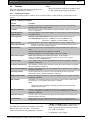
Summary of Features
The following table provides a summary of the controller features. Fuller details are provided later in this
section.
Table 5: Summary of Features
Features
Reader channels
Faceplate
Controller type and
software version
Power supply unit
Memory module
Memory backup battery
Onboard Relays
Alarm event managers
Dial-back facility
Protected communications
Remote acknowledgement
Transaction filtering
Multiple reader formats
Anti-passback
Comments
The K2200 series has a new terminal which allows you to have an in and out reader
(Readykey readers only) on each channel.
Each controller can be purchased without a faceplate. However, at least one is required
for basic configuration
Pressing the [?] key on the faceplate displays the controller type, the operating mode and
the software version.
Automatic Input Voltage Detection - PSU operates between 85vac and 250vac.
Lock Output Voltage 8amp PSU - 12 VDC at 2 amps and 24 VDC at 1amp.
4amp PSU is 12 VDC at 1amp and 24 VDC at .5 amp.
Physically identical to that used in the Readykey K2100 - only the software is new.
•
Maintains the system’s memory when all power, AC and external battery backup is
removed. Can be replaced without data loss.
There are 8 relays fitted to the Readykey K2200 Series Controllers. K2100 has only 4
relays.
Default settings applied when the database is initialized.
Readykey for Windows can override settings of relays 1-4 if required.
AEMs can be attached to all controllers in the series. (1 per channel)
Relays on the AEMs can be programmed to activate on certain events. (K1200
controllers can have 4 AEMs attached).
The controller can be set to up to dial a CNC when an alarm event happens. (Requires
Readykey for Windows).
Only establishes communications with CNC if master key code from CNC is recognized.
(Requires Readykey for Windows).
All alarm events generated must be acknowledged at PC to clear if this is set. (requires
Readykey for Windows).
Common transactions (e.g. request to exit) can be filtered out and not sent to the
administration system. (Requires Readykey for Windows).
Readers with Wiegand output can now be connected directly to the controller. (Requires
Readykey for Windows).
Anti-passback is a feature that prevents a key entering an area until it has been used to
leave that area. Local and global anti-passback is available.
Note:
Global anti-passback only available with Readykey for Windows V6 using the K2200
controllers as a master panel.
Master override input
Event time stamping
Download times
2.3.2
When active, this links the override input on slave door controllers to the master
controller. If triggered on the master, doors on slaves automatically opened. (Requires
Readykey for Windows).
Accuracy can be selected to be to the nearest second. Default is to the nearest minute.
(Requires Ready for Windows
Download times have been significantly improved. Typically, download times for the
Readykey K2200 Series Controllers are 30% faster than for the Readykey K2100/K1100.
Appearance
•
A RDR1 and RDR2 connectors which allow you
to connect a second Readykey reader on one
channel, giving the option of having an In and
Out reader on each door.
•
An additional 4 relay outputs.
The Readykey K2200 Series Controllers looks a little
different than earlier controllers. The board is
smaller and has the following additional connectors:
Bosch Security Systems | 7/03 | 17375 1.3 / 46513C
K2200 Series | Installation Guide | 2.0 K2200 Series Controllers
The inline fuses have also been replaced by on-board
resettable fuses - which are reset by unplugging the
terminal strip and plugging back in.
2.3.3
Faceplate
The Readykey K2200 Series Controllers faceplate is
the same as used on the Readykey K2100/K1100
controllers.
The door controllers can be purchased without a
faceplate. It is recommended that controllers without
faceplates are used only as slaves and that at least one
controller on a site has a faceplate. The faceplate is
detachable and can be installed on any controller.
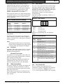
2.3.4
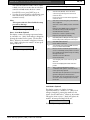
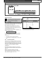
Software Version and Model Type
Pressing the [?] key on the faceplate will produce a
display similar to:
Figure 4:
Nnnn
Software Version and Model Type
Display
Mn
V-yx
In this case a Readykey K2200 with software
version 1.0. running in mode 2
nnnn =
controller type (2244 for K2200, 2222
for K2100)
Mn = refers to operating mode
n = 0 – for master door controller
(standalone system)
n = 1 – for MS-DOS system
n = 2 – for Readykey for Windows system
n = 3 – for slave door controller (any
system)
Vx-y =
is the software version number.
2.3.5
Power Supply Unit
The Power Supply Unit (PSU) is similar to that used
in the Readykey K2100. The PSU provides the
following features:
•
Automatic input voltage detection - the new
power supply will operate from a AC power
input of between 85vac and 250vac. There is no
longer a need for separate models for different
AC power sources.
•
Lock output voltage – The lock output voltage
can be set to 12 VDC or 24 VDC.
•
Power indicator - A red LED within the power
supply indicates the presence of ac input voltage.
•
Cooling fan – A cooling fan is used to assist in
keeping the controller and circuits cool.
Bosch Security Systems | 7/03 | 17375 1.3 / 46513C
2.3.6
EN | 12
Memory Module
The memory module used in the Readykey K2200
Series Controllers contains the setup configuration
and program.
K2200 Series | Installation Guide | 2.0 K2200 Series Controllers
•
2.3.7
Memory Backup Battery
The backup battery is provided to maintain the
system’s memory when all power, AC and external
battery backup is removed. The backup battery can
now be replaced without data loss. In order to
replace the battery:
EN | 13
Alarm events and buffer full (percentage set by
installer).
The dial-back numbers can be entered either at the
controller or, if you have Readykey for Windows
version 6, at the PC (recommended) and downloaded
to the controller.
2.3.11 Protected Communications
•
The module must be plugged into the door
controller.
When selected at the door controller, this feature is
'self-programming' and:
•
The door controller must be powered from the
AC power line or the sealed lead acid backup
battery in the panel case.
•
Allows the next dial-up by the CNC to be
accepted.
•
Stores the master key sent by the CNC in the
Readykey K2200.
2.3.8
On- Board Relays
There are 8 relays fitted to the Readykey K2200
Series Controllers. The default settings for these
relays are as follows:
When the CNC next dials the master door controller,
the controller will only establish communications if
the CNC sends the same master keycode as is stored
in the door controller.
•
Relay-1: Invalid key on door 1
•
Relay-2: Invalid key on door 2
•
Relay-3: Invalid key on door 3
To set this feature, see Section 6.1.7 Setting the Modem
Connection, Step 7. Table 21 shows a better description
of Protect Comms.
•
Relay-4: Invalid key on door 4
Note:
•
Relay-5: door/anti-tamper on any door
•
Relay-6: time profile-1
•
Relay-7: door left-open alarm on any door
•
Relay-8: system tamper
Note 1:
The default settings are applied when the database is
initialized either at the faceplate or from a PC.
Note 2:
Relays 1-4 are fully programmable to respond to a
wide range of events when being administered from
Readykey for Windows.
2.3.9
Alarm Event Managers
It is possible to program the relays on each AEM to
activate on certain events, including time profiles,
door alarms, etc. Because of this increased
functionality the way the responses are programmed
has changed. The details of the programming
changes are in the documentation provided with each
administration system.
2.3.10 Dial-Back Facility
The Multi-Site Systems administered by a CNC
feature applies only to systems connected through a
dial-up (PSTN or TCP/IP) modem to a CNC. If
using dial-up modems, you can now set any
Readykey K2200 controllers configured as a master
to dial back to the CNC in the event of an alarm
condition
When administered through Readykey for Windows
Version 6, dial-back is available either for:
•
Alarm events only, or
Bosch Security Systems | 7/03 | 17375 1.3 / 46513C
Available only on multi-site systems administered by a
CNC.
2.3.12 Remote Acknowledgement
Whenever a door alarm occurs at the controller a
relay is set. Once the alarm is acknowledged (when it
was successfully communicated to a master
controller, CNC or PC), the relay is reset.
When using Readykey for Windows, it is possible to
set alarms so that the relays are not reset until an
operator accepts the alarm at the PC. This is
particularly important if you are going to use the
more extensive relay programming now available.
To set this feature, see Section 6.1.7 Setting the Modem
Connection, Step 4. Table 21 shows a better description
of Remote Acknowledgement.
Note:
Available only on multi-site systems administered by a
CNC.
2.3.13 Transaction Filtering
On busy systems, performance can be improved by
filtering out the less important transactions such as
request to exit, free exit, etc. Now there are 5 groups
of transactions that the door controller can 'forget',
i.e. not send to the administration system.
To set this feature, see Section 6.1.8 Event Mode.
Note:
Available on all administration systems
K2200 Series | Installation Guide | 2.0 K2200 Series Controllers
2.3.14 Multiple Reader Formats
2.3.15 Anti-Passback
Readers with a 26-bit Wiegand output can be
connected directly to the door controller (see Figure
27 and Figure 28 for details).
Local Anti-Passback
Note:
If these readers are used, you can only connect one
reader per channel. If you require an in and out
reader, you must use lock sharing where two reader
channels are used to control the same lock.
EN | 14
Local anti-passback records which keys have been
used to enter an area. This information is then used
to determine whether or not a key can be used to
enter or leave the area. This can be used to prevent
keyholders passing their keys to others to gain entry.
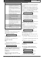
Local anti-passback only operates between the doors
on a single door controller with specific readers
allocated as entry (“Doors” 1 and 2) and exit
(“Doors” 3 and 4) - see Figure 4.
Note:
On the Readykey K1200, which only controls 2 doors,
Door 1 is entry and Door 2 is exit.
Figure 5:
Possible Reader Locations for Local Anti-Passback
There are two types of local anti-passback available:
1. Anti-Passback on Entry. When this feature is
active, any key used to enter an area cannot be
used to enter the area again unless it has first
been used to leave the area. Using the example
shown in Figure 5, if you use your key to enter
development, you cannot use the same key to
enter development unless it has first been used to
leave development. If the key is used again at an
entry door, a No Entry: Passback
transaction is produced and the lock will not
operate. Access will continue to be denied until
the key has been used at an exit reader.
2.
Anti-Passback on Exit. When this feature is
active, a key cannot be used to exit an area
unless it has first been used to enter the area.
This is only available when anti-passback on
entry is also active. Using the example shown in
Figure 5, if you have not used your key to enter
development (e.g. you came in with someone
else), you cannot use your key to leave
development. If the key is used again at an exit
door, a No Exit: Passback transaction is
produced and the lock will not operate. Access
will continue to be denied until the key has been
used at an entry reader.
Note:
If door monitoring is used, local anti-passback will only
be set if a key is presented and the door is opened.
Simply presenting a key will not set local antipassback. If door monitoring is not used, local antipassback will be set when a valid key is presented.
Bosch Security Systems | 7/03 | 17375 1.3 / 46513C
K2200 Series | Installation Guide | 2.0 K2200 Series Controllers
Timed Anti-Passback
Note:
Timed anti-passback also works with global antipassback.
Timed anti-passback is where you specify the period
for which a key is denied access. After the specified
period has elapsed the key will be allowed access
again, even if it has not been used to leave the area.
The time may be set to between 10 and 30 minutes
in 5 minute steps (10, 15, 20, etc.).
Using the time-out period means you could use antipassback without an exit reader. A car park, for
instance, may have an entry barrier with a reader.
When a key is used to raise the barrier, that key will
not be able to gain access again until the time period
expires. Provided that genuine use of the key is
unlikely to be needed within the time period, no exit
reader is required.
Global Anti-Passback
Global anti-passback is only available on Readykey
for Windows V6 cluster sites, i.e. dial-up sites which
have more than one controller on the site. It is not
available on the standalone system and it will not
work with CNC six wire bus sites.
Note:
Global anti-passback is implemented using passback on
entry. Passback on exit is only available if you are
leaving the site.
The controller uses the entry and exit areas specified
for each reader to determine exactly where you are.
Once you enter an area for which global antipassback has been set, re-entry is not allowed until
you have either left the area or until the passback
time-out has elapsed.
2.3.16 Master Override Input
This feature, when active, “links” the override input
of slave controllers to the master controller to which
they are attached. If the override input is triggered
on the master controller, the doors on any slave
controllers with the option set are automatically
opened.
2.3.17 Download Times
Download times for the Readykey K2200 Series
Controllers has been significantly improved.
Typically, download times are 30% faster than for the
Readykey K2100/K1100 controllers.
2.3.18 Compatibility with Previous Models
The Readykey K2200 Series Controllers replace the
Readykey K2100/K1100 and is compatible with
older Readykey door controllers.
Bosch Security Systems | 7/03 | 17375 1.3 / 46513C
EN | 15
Older Readykey products such as the K2000-N and
K2100 may be used as slave door controllers on the
six wire bus, along with Readykey K2200 Series
Controllers operating as the master or as other slaves.
However, some features will only be available on the
Readykey K2200 Series Controllers. Readykey
K2200 Series | Installation Guide | 2.0 K2200 Series Controllers
2.4
Specifications
2.4.1
Environmental
Table 6:
Door
Controllers
2.4.2
2.4.3
EN | 16
Cable
Table 8:
Cable Specifications
Environmental Specifications
Temperature
+32ºF to +104ºF
(0ºC to +40ºC)
Humidity
0% to 90% RH
(noncondensing)
K2001/K
3001
Series
Readers
Type
6 conductor,
multi-stranded,
unshielded
cable
Lock
Output
2 conductor,
multi-stranded
Six-Wire
Bus
6 conductor,
multi-stranded,
unshielded
cable.
Power Supply
The Readykey K2200 Series Controllers has an
integral AC power supply. It is capable of
automatically sensing the input voltage and will
therefore operate on a 110-120vac or 220-240vac, 50
Hz or 60 Hz AC power supply without the need for
switch setting.
The lock output is switch selectable between 12 VDC
and 24 VDC. The lock output voltage applies to all
the lock outputs.
Electrical rating for the auxiliary output is 500 mA.
Full load power heat dissipation is 26 W @ 250 and
115 VAC door controllers.
Table 7:
AC Line
Input
Power Supply Specifications
Voltage
Fuse Rating
Connector
Lock Output
Output Voltage
Fuse Rating
Max. Current
Battery
Backup
Input Voltage
Fuse Rating
85 VACvac to 250
VACvac 50/60 Hz
power input
3.15 A 20 mm
HBC fuse (in AC
connector) for 4
Aamp PSU
Standard IEC
connector, right
angle socket
supplied
12 VDC VDC or 24
VDC VDC, switch
selectable.
Re-settable fuse on
board, one per
channel
2 amp per channel
at 12 VDC VDC
1 amp per channel
at 24 VDC
12VDC VDC or 24
VDC VDC,
depending on lock
output
Re-settable fuse on
board
Bosch Security Systems | 7/03 | 17375 1.3 / 46513C
Distance/ Gauge
Up to
24 AWG
750 ft
(229 m)
Up to
20 AWG
1500 ft:
(457 m)
Up to
18 AWG
3000 ft:
(914 m)
Depends on distance to
lock and the current drawn
by the lock.
Usually 18 AWG (1.2 mm)
will be sufficient.
Overall
3000 ft.
length of
(1000 m)
bus (max):
Between
1500 ft.
controllers
(500 m)
(max):
18 AWG
K2200 Series | Installation Guide | 3.0 Administration Systems
3.2
3.0 Administration Systems
EN | 17
Faceplate Administration – 16-door
Table 9:
This section looks briefly at the administration
systems that can be used with the door controllers.
In it, we’ll look at:
•
Faceplate administration (standalone systems).
•
PC-based administration (Readykey for Windows
systems).
Emphasis is placed on the Readykey for Windows
V6 system as this allows you to make full use of all
the features provided by the Readykey K2200 Series
Controllers.
3.1
Introduction
There are several ways of administering Readykey
Access Control Systems. Different methods allow
greater numbers of doors or personnel to be
controlled and door controllers to be located at
greater distances from where the system is
administered.
This section looks at the following systems:
1. Faceplate Administration. For small standalone
systems, administration can be carried out
entirely via the faceplate. This is only really
suitable for small systems (less than 16 doors)
with small numbers of personnel.
2. Readykey for Windows with PC Interface Kit.
This allows up to 32 doors to be controlled from
a PC running Microsoft Windows. This provides
a user interface which is much easier to use and
also provides additional control over the
controller relays and AEM inputs and outputs.
3. Readykey for Windows with a CNC. This
provides the option of having multiple (remote)
sites connected via dial-up modems. Both single
and multiple site systems are described.
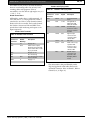
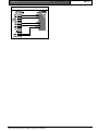
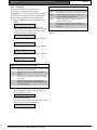
Figure 6:
Part Number
Bosch
PAC
47491
17376
Name of Document
Readykey K2200 Series
Controllers User Guide
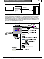
The door controllers are normally supplied with a
faceplate containing a 48-key keypad, a 16-character
display and a key reader. However, it is possible to
purchase controllers without a faceplate if required.
Readykey recommend that controllers without
faceplates are used only as slaves and that at least one
controller on a site has a keypad to enable
programming. The simplest way of administering an
access control system is to use this panel to carry out
all the programming. Keys are added by presenting
them to the faceplate reader, data is added, modified
or deleted using the keypad and display.
When using this form of administration, a serial
printer may be connected to the master controller,
this will print events as they occur and can also be
used to print the contents of the controller's database.
This system limits are as shown in the following
table.
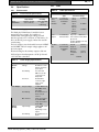
Table 10:
16-Door Limits
Maximum Number of
Personnel
Maximum Number of Doors
16
Access Codes
Time Profiles
Editors
Auxiliary Alarm Points
128
32
32 (plus master)
32 per door controller
System Diagram – Faceplate Administration
Bosch Security Systems | 7/03 | 17375 1.3 / 46513C
See these Documents – Faceplate
Administration – 16-door
4000
K2200 Series | Installation Guide | 3.0 Administration Systems
The slave controllers can be any of the Readykey
K2200 Series Controllers.
Bosch Security Systems | 7/03 | 17375 1.3 / 46513C
EN | 18
K2200 Series | Installation Guide | 4.0 Six-Wire Bus
EN | 19
4.1
4.0 Six-Wire Bus
This section looks briefly at Readykey’s proprietary
communications link between controllers - the six
wire bus. In it, we’ll look at:
•
Cable specifications for the six-wire bus.
•
Possible configurations.
•
Controller addressing.
The six-wire bus is Readykey's proprietary
communications link for locally connecting door
controllers. It uses up to 3000 ft. (1000 m) of
standard, unshielded signal cable to connect door
controllers. No single length of cable should be
longer than 1500 ft. (500 m).
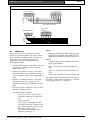
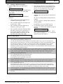
Figure 7:
Six Wire Bus Wiring Configuration
Bosch Security Systems | 7/03 | 17375 1.3 / 46513C
Cable Specification
Readykey recommend that you use multi-stranded,
unshielded, 6/8-conductor 24 AWG (0.5 mm /
0.22mm²) alarm or signal cable. If you do use
shielded cable, you should reduce the maximum
distance by 2 to 3 times depending on the
capacitance of the cable.
This is a linear bus and, where possible, should be set
up as shown in the following diagram. The total
length of the bus should not exceed 3000 ft. (1000
m), and no single length should be longer than 1500
ft. (500 m).
Note:
Branches/spurs are allowed provided they are no longer
than 33 ft. (10 m) in length. The length of the spurs
should be included as part of the overall length. A
maximum of four spurs recommended.
K2200 Series | Installation Guide | 4.0 Six-Wire Bus
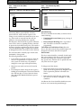
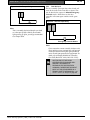
Figure 8:
EN | 20
Six-Wire Bus Wiring
Master Controller
+V
Slave Controller
+V
AB1 AB2 DSD USD -V
AB1 AB2 DSD USD -V
Red
Yellow
White
Green
Blue
Black
+V
AB1
AB2
DSD
USD
-V
Up to 6 Further Slave Controllers
Slave Controller
Network Controller
1
2
6
3
7
4
8
SIX WIRE BUS
+V AB1 AB2 DSD USD -V
5
9
+V
AB1
AB2
DSD
USD
-V
Red
Yellow
White
Green
Blue
Black
Up to 31 Further Slave Controllers
4.2
Addresses
The six-wire bus works by each door controller
having its own unique address. The order in which
door controllers are addressed does not matter nor
do they have to be numbered consecutively.
Depending on the type of administration, the
following are possible:
Note 1:
When being addressed by the CNC, a maximum of 32
controllers can be addressed. When polling, the CNC
display shows the address as 0-9 and A-W (10 to 32).
Note 2:
A multi-site network has sites numbered according to
the type of site as follows:
•
Faceplate Administration - One master controller
(system type 0) and up to 3 slave controllers,
addressed 2,3 and 4.
Site 1 - via six wire bus, one master and up to 32
slaves.
•
Readykey for Windows 16 Door - One master
controller (system type 2) addressed 1 and up to
3 slave controllers (system type 3), addressed 2, 3
and 4.
Sites 34-128 - via RS-232, one master controller only.
•
Readykey for Windows 32 Door - One master
controller (system type 2) and up to 7 slave
controllers (system type 3), addressed 2,3,4,5,6,7
and 8.
•
Network Controller - Single-site - Up to 32 slave
controllers, addressed 1 to 32.
•
Network Controller - Multi-site
-
Via the six wire bus: - Up to 32 slave
controllers (system type 3), addressed 1
to 32.
-
Via the serial link:
Up to 32 sites comprising one master
controller (system type 2) address 1 and
up to 7 slave controllers (system type 3),
addressed 2,3,4,5,6,7 and 8.
Up to 95 sites comprising one slave
controller (system type 3).
Bosch Security Systems | 7/03 | 17375 1.3 / 46513C
Sites 2-33 - via RS-232, one master and up to seven
slaves.
Site numbers allocated are dependent on the type of
site and are not necessarily sequential, e.g. a network
could comprise sites 1, 2, 3, 34 and 35.
K2200 Series | Installation Guide | 5.0 Installation Details
5.0 Installation Details
This section is takes you through the various steps in
fitting the door controllers. It contains:
1. A brief description of each controller - what it
looks like, dimensions, etc.
2. Details on how to fit and test the hardware controllers, readers, etc.
5.1
5.1.1
Readykey K2200 Series Controllers
- Description
Multi-Function Door Controllers (K2200
and K1200)
Physically, all the door controllers look alike with the
main difference being in the number of reader
channels and AEMs that can be supported.
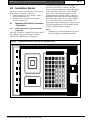
Figure 9:
EN | 21
The unit comes complete with a power supply. It
can also be ordered with or without a faceplate.
There are 2 types of faceplates available, depending
on the readers that will be used. Order a K2200,
which comes with the K2108 faceplate, (has the
Traditional Readykey Reader built in). Order the
K2200-KP, which comes with the K3108 faceplate
(has the KeyPAC reader built in). Order a K2200LF, for the controller only, Less Faceplate. It is
required that at least one faceplate is used per system.
The following diagrams show the Readykey K2200
on a skirt with and without a faceplate.
Note:
All dimensions of the skirt and metal case are given in
the section dealing with installing the controller.
Readykey K2200 Door Controller with Faceplate Fitted
Bosch Security Systems | 7/03 | 17375 1.3 / 46513C
K2200 Series | Installation Guide | 5.0 Installation Details
EN | 22
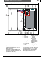
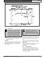
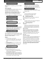
Figure 10: Readykey K2200 Door Controller with Faceplate Removed
12345678910 11 -
Power Supply
LED
Baseplate
Mains Input
Option Reset
Reset Switch
Status LEDs
Case Tamper
Override
Six-Wire Bus
Spare
12 - RS-232
13 - Reader Channels
and Lock
Outputs
14 - Front Panel
Connector
15 - Memory Battery
16 - Memory Module
17 - Battery
18 - 12 V/24 V
Auxiliary Output
19 - Relays
The door controllers consist of:
•
A printed circuit board and power supply both
fitted to a steel baseplate.
•
An optional, removable faceplate fitted to the
power supply and baseplate that connects to the
circuit board via a ribbon cable.
•
A memory module containing the database.
Bosch Security Systems | 7/03 | 17375 1.3 / 46513C
•
A second, protective, “cover plate” sitting on top
of the main circuit board. This cover protects
the components on the main board and has a
label, which provides information on the
connectors, status LEDs and so on.
K2200 Series | Installation Guide | 5.0 Installation Details
EN | 23
Power Supply
5.3
The metal cased power supply unit is fitted on the
left-hand side of the baseplate. This unit will
automatically adjust to the local AC power supply,
accepting input voltages between 85 VAC and 250
VAC at 50/60 Hz. The power input uses a standard
IEC connector; a right-angle socket is supplied.
The door controller may be mounted in the metal
case (part number K2120 of D8103) supplied
separately by Bosch Security. Make sure that access
can be gained to the door controller independently of
the access control system itself.
The output from the power supply is fed to the
circuit board by an 8-pole connector.
Faceplate
The removable faceplate, if fitted, contains a key
reader, on the left-hand side, a keypad and a 16
character display. The panel is secured by two tabs
that fit into slots in the power supply on the left-hand
side of the baseplate, and by two spring clips on the
right-hand side of the panel that attach to the
baseplate. A ribbon connector plugs into a socket on
the circuit board at the top right of the board.
The faceplate and controller can be purchased as
separate items but it is recommended that only slave
controllers are purchased without a faceplate. There
should be at least one controller (master) on a site
with a faceplate.
Memory Module
This small board sits on top of the cover plate and
contains the software and database memory. A small
removable battery maintains the database memory
for six months in the absence of mains or battery
power.
5.2
Introduction
This is a brief outline of the steps that will be taken in
the following sections. This describes the installation
and testing of the door controller independently of
the administration system.
It is possible to test all the reader and lock functions
before making any network or communications
connections. You are strongly advised to follow the
order shown below. In this way you will be able to
identify any problems before going on to the next
stage.
1. Sitting and Fitting the Controller, including
fitting of the Readykey metal case if used.
2. Installation of Readers, including door contacts,
request-to-exit switches.
3. Wiring of Locks
4. Testing of Readers, Locks etc.
5. Network connections, six-wire bus and/or serial
links where applicable.
Note:
Further information on administering the K2200 is
included in Readykey K2200 Series Controllers User
Guide (Radx P/N: 47491, PAC P/N: 17376).
Bosch Security Systems | 7/03 | 17375 1.3 / 46513C
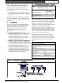
Installing the Controller
If several door controllers are to be connected using
the six-wire bus, it is usually better to distribute the
controllers so they are closer to the doors. This
should reduce the length of cable needed for readers
and locks.
K2200 Series | Installation Guide | 5.0 Installation Details
EN | 24
Figure 11: Recommended Wiring Layout
Reader
Controller
Lock
If the system is to be administered from
the faceplate, operators will be spending
time programming at the controller. You
should therefore ensure that the
controller is mounted in a suitably warm,
dry and well lit location. The display
should be at about eye level for most
comfortable use.
5.3.1
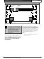
Metal Case
The door controller is contained in a metal case.
There are two metal case options. Both options have
space for two 12 VDC 7AH lead acid batteries if
required. The metal case dimensions for each option
are shown in Figure 12 and Error! Reference
source not found..
Bosch Security Systems | 7/03 | 17375 1.3 / 46513C
The metal case should be fitted to a wall using
appropriate fixing screws. Use the central keyhole
slot to hang the case initially, and use the remaining
fixing holes as a template. There are several
knockouts, shown in Figure 11, provided for cable
routing. Use conduit or trunking when bringing
surface mounted cables into the case.
Note:
The metal case is usually locked with only service
engineers allowed access.
K2200 Series | Installation Guide | 5.0 Installation Details
EN | 25
Figure 12: Metal Case
5.3.2
Faceplate
The faceplate is secured by two tabs that fit into slots
in the power supply on the left-hand side of the
baseplate and by two spring clips on the right-hand
side that attach to the baseplate. The ribbon
connector should be plugged into the socket on the
circuit board at the top right of the board.
The door controller fits in the metal case using two
slots that fit over tabs on the back of the case. You
should ease the tabs on the case forward slightly to
make locating the door controller easier. The base
plate should then be secured using the single tab at
the bottom of the baseplate using the self-tapping
screw supplied.
5.3.3
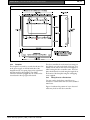
Fitting Direct to a Flat Surface
You may wish to fit the door controller in an
enclosure or cabinet other than one of the standard
metal cases.
Figure 13 indicates the position of screw slots and
cable entry holes on the door controller.
Bosch Security Systems | 7/03 | 17375 1.3 / 46513C
K2200 Series | Installation Guide | 5.0 Installation Details
EN | 26
Figure 13: Rear View of Door Controller Base Plate
5.3.4
Power Supply
The database is stored in battery-backed
memory and will be preserved whether
the controller is powered or not. This
backup will last up to 3 years provided
that the controller is normally powered.
The battery, located on the memory
module, can be replaced without losing
data. This is recommended every 3 years.
Note:
The backup will be preserved for 6 months if the
controller is not powered.
AC Supply
AC power, between 85 VAC and 250 VAC, 50/60
Hz, should be supplied to the controller through an
illuminated, unswitched outlet. A right angle IEC
plug is supplied.
A GROMMET MUST BE FIXED TO THE
HOLE THROUGH WHICH THE AC
POWER WOULD PASS. THIS IS TO
PREVENT THE METAL CASE CUTTING
THE AC LEAD IF THE LEAD IS PULLED
ON.
Power Indicator
A red LED is situated within the power supply. It is
visible through a small hole about 3 in. (75 mm) from
the top on the left-hand side of the power supply
case.
If the door controller is operating off the AC power
supply, whether the battery is connected or not, the
LED will be lit.
If the AC power supply fails and the unit is running
from the backup battery, the LED will be
extinguished.
5.3.5
Lock Output Voltage
The lock output voltage is set for all doors on the
controller using a switch accessible through the top
edge of the power supply. 24VDC allows 1 amp of
current draw per output, 12VDC allows 2 amps of
current draw per output.
Bosch Security Systems | 7/03 | 17375 1.3 / 46513C
K2200 Series | Installation Guide | 5.0 Installation Details
5.3.6
Battery Backup
The 12VDC 7AH battery (if in a fully-charged, good
condition) provides approximately 2.0 hours of
standby time for a fully loaded system.
A battery charging facility is available that can
provide up to 0.5 A at 13.8 VDC or 0.25 A at 27.6
VDC.
Door Controllers
The battery backup voltage must match
the lock output voltage, i.e. 12 V VDC or
24 V VDC. You may use two 12 VDC
batteries in series to provide 24 VDC.
The capacity of the battery required should be
calculated based on:
EN | 27
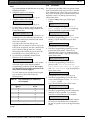
Example:
A 500 mA lock strike with a 5 second lock release time,
operating 50 times an hour would give:
CLC = (500 x 5) x 50 / 3600 = 35 mA
Note:
If you have any doubt about the current drawn by a
lock, you should measure it at the controller using a
meter.
The maximum current that should be drawn from
each lock output is:
2.0 A at 12 VDC 1.0 A at 24 VDC
In Table 11 record the type and current consumption
of each lock fitted.
•
The current consumption of the door controller
(1 A).
Table 11: Continuous Lock Supply Current
•
The current consumption of the devices attached
to the reader channels (up to 800 mA).
Channel
•
The current consumption of the locks when
operating normally (up to 2 A each).
•
The type of lock, continuous (fail-safe) or
intermittent (fail-secure).
•
The length of time the system should operate
without mains power.
•
The following tables will help you estimate the
current.
Lock Supply Current
For continuous, or fail-safe locks the continuous lock
supply current is the current drawn by the lock. For
fail-secure locks, however, you need to estimate the
equivalent continuous current by using the following
equation:
Figure 14: Continuous Current Estimation
Equation
CLC = {Lock Current Rating x LRT} x
NOP / 3600
where
CLC = Equivalent Continuous Lock Current
LRT = Lock Release Time (in seconds)
NOP = Number of Operation per hour
The lock current rating should be indicated in the
lock specification.
Bosch Security Systems | 7/03 | 17375 1.3 / 46513C
Type:
Continuous/
Intermittent
Continuous
Lock Current
1
2
3
4
Total =
Reader Supply Current
There is a maximum of
200 mA available per reader channel on the 18 V
supply. Readykey readers of all types draw
approximately 90 mA each continuously. If you fit
Alarm Modules or AEMs, a reader combiner or
Wiegand interface unit, you should ensure that the
maximum current available, 800 mA, is not
exceeded.
K2200 Series | Installation Guide | 5.0 Installation Details
EN | 28
In the table at the right record a current consumption for each device fitted:
Table 12: Total Reader Channel Current
Channel
1
2
3
4
Reader Current 1
35 mA (see Note 1)
Reader Current 2
100 mA (see Note 2)
Wiegand\Magstripe
Reader 50 mA
Module Relays
30 mA
Total:
Must not exceed
200 mA/channel
Note 1:
Note 4:
Reader Current 1 applies to the readers with flying
leads
(15 mA idle, 35 mA active).
Note 2:
Only include a value for the reader current if the
Wiegand reader is powered from the Wiegand interface
unit’s 5 VDC output or the 18 VDC reader supply
Note 5:
Reader Current 2 applies to the readers with screw
terminals as well as the panel mount reader.
Include 40 mA for each AEM that is connected to a
reader channel.
Note 3:
When using a reader combiner, you should include the
current of the combiner in its column plus the total
current for both readers in the reader column.
Determining Total Power
Alarm Controller
The door controller itself consumes 1 A before the
addition of any readers or locks.
The capacity of the battery required should be
calculated based on:
For each 100 mA of reader channel current, as
determined above, an additional 150 mA should be
allowed. This is due to several factors involved in the
generation of the 18 VDC VDC supply.
•
The current consumption of the alarm controller
(1 A).
•
The current consumption of the devices (AEMs,
detectors, etc.) attached to the controller, up to a
maximum of 800 mA
Table 13: Determining Total Power
Door Controller
1
Total:
A
A
A
A
The above figures are all stated in Amps, 1 A = 1000
mA.
Bosch Security Systems | 7/03 | 17375 1.3 / 46513C
The length of time the system should operate without
mains power.
Note:
Each AEM can be powered from the controller or via a
separate power supply. The current drawn by each
AEM is a maximum of 40 mA.
K2200 Series | Installation Guide | 5.0 Installation Details
EN | 29
Using an External Charger
Standby Battery Requirements
For door controllers, the battery voltage
should match the lock output voltage.
Now that you know the total continuous current
requirement of the door controller plus readers, locks
and ancillaries, you should multiply this figure by the
number of hours standby needed.
In order that a fully discharged battery can recover to
a fully charged state within 24 hours, you should
consider using an external charger when using more
than a 7 Ah battery. Use the wiring shown below.
Note:
The auxiliary battery charger output must not exceed 2
VDC over K2200 battery output.
In the enclosure supplied, there is room for two 12 V
7 Ah batteries. If this does not provide sufficient
backup, the batteries must be located outside the case
or the controller mounted in a larger case.
Note:
A door controller with a continuous current of 2 A will
require at least a 4 Ah battery to provide 2 hours cover
(2 A x 2 hours = 4 Ah).
The Ah rating of a battery is usually
determined when discharged over a 10
or 20 hour period. If a fully charged
battery is discharged over a shorter
period than this, as in the example above,
it will last for less time than its rating
suggests. You should consult the battery
manufacturer's correction factor charts to
determine a more accurate figure. than
expected.
Figure 15: Using an External Battery Charger
K2200
5A Slow Blow
5A Slow Blow
Battery
7 Ah
7 Ah
Battery Charger
Bosch Security Systems | 7/03 | 17375 1.3 / 46513C
K2200 Series | Installation Guide | 5.0 Installation Details
5.4
Installing Readers and Locks
All the features described below can be
programmed and tested, where
necessary, at the faceplate. Details of
how to do this are given in Section Error!
Reference source not found.. However, if
the door controller is going to be
administered from a PC-based system,
you will need to program these features
from there as well. You are advised to
use the faceplate to test the installation of
the door controller, readers and locks and
then, once communications are
established, initialize the door controller
and program the features at the
administration PC.
EN | 30
Readykey Low Profile Reader - K2001 + K2001W
A reader suitable for interior or exterior use and
comes in both black and white.
Readykey PIN Reader and Readykey Surface
Mount - K2001-P
This device requires a PIN number to be entered, as
well as a key to be presented, as an extra level of
security. The need to use a PIN as well as a key can
be controlled using a time profile.
Readykey Vandal Resistant Reader - K2002 +
K2001B
A stainless steel or brass reader particularly suitable
for exterior use, where resistance to abuse is
important.
Readykey Mullion Reader - K2003 + K2003W
How to fully commission a PC-based system is
described in the documentation supplied for that
system.
This device is a slimline version of the low profile
reader, suitable for mounting on door frames etc,
comes in both black and white.
5.4.1
Readykey Panel Reader- K2025
KeyPAC K3000 Series Readers
These readers read KeyPAC electronic keys and ISO
thickness ID cards they do not read the earlier
Readykey ID devices. Make sure that you specify
KeyPAC whenever you purchase electronic keys and
ID cards.
KeyPac Low Profile Reader - K3001 + K3001W
A reader suitable for interior or exterior use and
comes in both black and white.
KeyPac Vandal Resistant Reader - K3002 +
K3002B
A stainless steel or brass reader particularly suitable
for exterior use, where resistance to abuse is
important.
KeyPAC Mullion Reader - K3003 + K3003W
This device is a slimline version of the low profile
reader, suitable for mounting on door frames etc.
Comes in both black and white.
KeyPAC Extended Range Reader - K3004 +
K3004W
This device is weather resistant and suitable for
indoor and outdoor use. Keys and Cards are read at
a distance of up to 10 inches. Comes in both black
and white.
5.4.2
K2000 Series Readers
These readers read Readykey ID electronic keys and
ID cards. They do not read the newer KeyPAC
elctronic keys and ID cards. Make sure that you
specify PAC ID (not KeyPAC) whenever you
purchase electronic keys and ID cards.
Bosch Security Systems | 7/03 | 17375 1.3 / 46513C
A reader designed for mounting in a steel panel, such
as a door entry system or elevator cabs.
KeyPAC ID Devices
The KeyPAC range will not work with the earlier
Readykey devices. The following are part codes for
compatible electronic keys and ID cards:
•
K3010-10- KeyPAC Prox Keys, packs of 10
•
K3011-10- KeyPAC Prox Cards, packs of 10
•
K3011M-10- KeyPAC Prox Cards with Magnetic
Stripe, packs of 10
Readykey 2000 Series ID Devices
The K2000 Series devices will not work with the
newer KeyPAC devices. The following are part codes
for compatible electronic keys and ID cards:
•
K2010-10- Electronic Key, packs of 10
•
K2011B-10- Cards with logo, packs of 10
•
K2011M-10- Cards with Magnetic Stripe, packs
of 10
•
K2011W-10- Cards, White (no logo), packs of 10
The Readykey K2200 Series Controllers have either
four or two reader channels. Each reader is wired
independently using up to 3000 ft. (1000 m) of 6conductor cable.
K2200 Series | Installation Guide | 5.0 Installation Details
Reader Wiring
Figure 16: Reader Wiring Diagram - Terminals
Figure 17: Reader Wiring Diagram - Flying Lead
Bosch Security Systems | 7/03 | 17375 1.3 / 46513C
EN | 31
K2200 Series | Installation Guide | 5.0 Installation Details
EN | 32
Figure 18: Reader Wiring Diagram - In/Out Readers
Use the most appropriate reader for the location bearing in mind, internal or external, vandal resistance,
decor, panel mounting, etc.
Note:
The in/out reader option is only available if Readykey readers are used. If you are using Wiegand or Magstripe readers
and require in/out readers, you must use lock sharing where two reader channels operate the same lock.
Reader Fitting
See the documentation supplied with each Readykey
reader for specific details for fitting that type of
reader.
In general:
•
•
•
Readers should be mounted at a convenient
height, usually at about the height of a door
handle, on the unhinged side of the door.
Readers should be mounted at least 3.3 ft. (1 m)
apart to prevent any interaction between them.
Be particularly careful with this distance when
placing readers on each side of the same door.
Consider future service requirements such as
access to cables, etc.
Reader Cabling
Use unshielded, multi-stranded, tinned copper signal
cable, the type commonly used in alarm installations.
A minimum of 24 AWG (0.5 mm), cable is required
(reader, request to exit and door contact). For
example, some readers have a sounder which require
an additional core to make use of the feature.
Bosch Security Systems | 7/03 | 17375 1.3 / 46513C
The maximum reader cable length is dependent on
both the reader type and cable gauge as detailed
below. For example, the cable length for the Mullion
and standard plus readers is:
Full details are provided in the documentation
supplied with each reader.
Table 14:
Appropriate Wire Gauge based on
Length
Length
up to 750 ft. (250 m)
up to 1500 ft. (500 m)
up to 3000 ft. (1000 m)
Wire Gauge
24 AWG (0.5 mm)
20 AWG (1.0 mm)
18 AWG (1.2 mm)
Four conductors are used to connect the reader itself,
the other conductors can be used for the optional
request to exit and door monitoring signals (see
Section 5.4.3 Request to Exit (DR2) on page 34 and see
Section 5.4.4 Door Monitoring (DR1) on page 34).
K2200 Series | Installation Guide | 5.0 Installation Details
The readers are not prone to electrical interference,
however avoid routing cable close to heavy load
switching cables and equipment. If this is
unavoidable, cross the cable at right angles every 3.3
- 6.6 ft. (1 - 2 m).
Reader Connections
All Readykey readers have 4 visible terminals, +V,
VCA, SIG and -V, or a flying lead. Each reader is
connected to one of the 4 reader channel terminal
blocks on the door controller. Each reader channel
has 2 further connections, DR1 and DR2. These
provide door/cable monitoring and request to exit
inputs respectively.
EN | 33
Readers with Flying Leads
Table 16:
Readers with Flying Leads
Connects to
Controller
GND
Color
Signal
Description
Black
-V
+18V
Red
+12V
GND
Yellow
SNDR
SIG
White
SIG
LED
Green
Brown
n/c
VCA
Blue
DR1
Power and signal
return
Unregulated 12
VDC input 9-28
VDC, 35 mA Max.
Sounder input,
active low. Pull to
ground to activate
sounder
Signal output.
connect to door
controller reader
channel SIG
Not used
Valid code accept,
operates LED.
Connect to door
controller reader
channel, LED.
Reader tamper
connection (not
required on the
Readykey K2200
series)
Readers with Terminals
Table 15: Readers with Terminals
Connects to
Controller
+V
LED
Reader
Markings
+V
VCA
DR2
DR1
SIG
SIG
GND
-V
Description
Supply: 18 V
Valid code accepted,
illuminates the green LED
at the reader when a valid
key is presented.
Request to exit.
Door monitoring
The signal from the reader
to the controller.
Supply: 0 V
Note:
If an in\out reader is being used (Readykey readers
only), the Sig from the second reader connects to the
relevant Rdr connection - Rdr1 on Channel 1, Rdr2 on
Channel 2, etc., see Figure 18,
Bosch Security Systems | 7/03 | 17375 1.3 / 46513C
K2200 Series | Installation Guide | 5.0 Installation Details
5.4.3
EN | 34
5.4.4
Request to Exit (DR2)
Door Monitoring (DR1)
Wiring Detail
Wiring Detail
Figure 20: Wiring for Door Monitoring
Figure 19: Request to Exit Wiring Diagram
Door
Controller
GND
DR2
N/O
Request to Exit
Door Monitoring
Connecting DR2 to ground (GND) will always
operate the lock; ensure that the request to exit
wiring is not accessible from outside the secure area
(e.g. if the reader is removed from the wall, the
request to exit wiring should not be exposed).
The Request to Exit switch allows persons within the
secure area to leave by signaling the door controller
to operate the lock without using a key. The switch is
necessary when door monitoring is used (see Section
5.4.4 Door Monitoring (DR1)) to enable the controller
to distinguish between a forced door and a valid exit.
The switch should be 'normally open' which closes
momentarily when pressed.
The following should be noted:
•
It is possible to locate the switch away from the
door, at a reception desk or as part of a door
entry system. In which case, it is possible to
change the event report to Request for Entry.
•
More than one switch can be used if wired in
parallel.
•
If an attempt is made to keep the door open by
holding down the Request to Exit switch then the
door will lock after 5 cycles of the lock release
time and an RTE Button Held Down report is
produced.
The door controller has the ability to monitor a door
contact allowing:
•
Unauthorized Access Alarms giving warning of
a forced door.
•
Door Left Open Warning after a set period of
time. The time is set when the controller is
programmed.
Cancellation of Lock Release Time allows the
door to lock after someone has passed through even
though the lock release time has not expired
Door Contact
The door contact should be a normally closed switch
that is open whenever the door is open. Care should
be taken when fitting door contacts to ensure that
they operate only when the door is opened and close
only when it is secure again.
To help prevent false alarms:
•
Keep reed switches away from large magnetic
fields, such as those generated by magnetic locks.
This is a particular problem with metal door
frames.
•
Ensure that the switch does not operate if the
door moves in its frame, in draughty or windy
conditions.
An efficient door closer should be fitted that secures
the door once someone has passed through.
Bosch Security Systems | 7/03 | 17375 1.3 / 46513C
K2200 Series | Installation Guide | 5.0 Installation Details
5.4.5
EN | 35
Note:
Emergency Override/Free Exit
There is a special case where both the DR2 and DR1
signals are interpreted differently to the way
described for door monitoring. The DR2 signal is
used to monitor an emergency switch, such as a
break glass, and DR1 provides a Free Exit report.
When this feature is used there is no door alarm
monitoring. For details on how to enable this feature,
refer to Readykey K2200 Series Controllers User Guide
(Bosch P/N: 47491, PAC P/N: 17376).
Figure 21: Emergency Override / Free Exit Wiring
Door
Controller
Reader
GND
DR1
-VE
DR2
N/O
N/C
Break Glass
Request to Exit
Special Case for Emergency Override and Free Exit
Emergency Override
When connected as shown in Figure 21, operating
the break glass will open the door and produce an
Emergency Override On report. When the
switch is restored an Emergency Override Off
report is produced and the door will be locked again.
THIS FEATURE SHOULD NOT BE
FITTED AS THE SOLE MEANS OF
ESCAPE.
Free Exit
When this option is set, pressing the Request to Exit
switch will produce a Free Exit report. The door
contact will allow door left open warnings to be
produced.
A normally closed switch may be used to operate as
a request to exit switch, in addition to having a door
contact switch in series (see Figure 21). An additional
special lock mode (Option 8) needs to be set, in
addition to option 2, to allow this feature (see Table
24).
Note 1:
Using this arrangement, the lock will operate whenever
DR1 is opened - this means that care should be taken
that the door contact cannot be broken from the secure
side of the door.
Note 2:
As free exit was designed to work with a door contact
or pushbar the door contact “bounce time” is applied
and the response will be slow if used like an Request to
Exit switch (1.25 seconds).
Bosch Security Systems | 7/03 | 17375 1.3 / 46513C
N/C
Door Contact
K2200 Series | Installation Guide | 5.0 Installation Details
5.4.6
EN | 36
Lock Output
Wiring Diagram
Figure 22: Lock Output Wiring
Door
Controller
Electric Release or Lock
LL+
MOV
+
MOV
+
Fail-safe or Fail-secure lock
LL+
Fail-safe lock with safety
Break Glass
N/C
Break Glass
All locks should be fitted according to the
manufacturer's instructions.
The door controllers provide a lock output for each
reader channel. These outputs are capable of
providing either 12 VDC or 24 VDC. The lock
output on each channel must not be able to exceed
2.0 amps at 12 VDC or 1.0 amp at 24 VDC. The
lock voltage is set using a jumper on the right hand
side of the power supply
Each lock output is protected by resettable fuse on
the controller. Two status LEDs are also provided for
each lock output. These operate as follows:
•
•
Fail Safe Locks. Both the red and green LEDs
are normally off. When a valid key is presented
to a reader, both LEDs come on for the duration
of the lock release time. A fault is indicated
when only the red LED is lit.
Fail Secure Locks. Both the red and green LEDs
are normally on. When a valid key is presented
to a reader, both LEDs go off for the duration of
the lock release time. A fault is indicated when
only the red LED is lit.
Each output can be independently set as fail-safe
(power to lock) or fail-secure (power to unlock).
The cable between the door controller and the lock
should be of such a gauge as to provide at least the
minimum voltage required to operate the lock. The
resistance of the cable and the current drawn by the
lock will determine the type of cable.
Bosch Security Systems | 7/03 | 17375 1.3 / 46513C
Lock Supervision
All locks must be fitted with a means of suppressing
back Electro-Motive Force (EMF) 'spikes' generated
by most electric releases, especially magnetic locks.
All Readykey door controllers and readers are
supplied with MOVs (metal oxide varistors). If large
currents are used (i.e. >1 A) use the large MOV
supplied with the door controller. If small currents
are used (i.e. <1 A) use the small MOV supplied with
the reader.
The MOV will prevent long term damage being
done to the door controller. Whenever possible this
device should be fitted across the lock terminals. If
for any reason, the lock terminals are inaccessible,
the MOV may be fitted across the lock output.
Safety
Any door that is considered a fire door or is on an
escape route must have some means of overriding
the electric release in an emergency. Usually this is
achieved by the use of fail-safe locks (power to lock)
fitted with a normally closed break-glass in the lock
supply. When the break-glass is operated, the supply
to the lock is broken and the door will be released
without any intervention from the door controller.
5.4.7
Lock Sharing
Note:
This is only required when the in/out readers do not
have a Readykey output (i.e. Wiegand or Magstripe
readers). Where the readers have a Readykey output
you can have two readers on the one channel.
K2200 Series | Installation Guide | 5.0 Installation Details
When using a reader on each side of a door to
monitor both entry and exit, it is only necessary to
feed one lock. Both the entry and exit reader will
operate the same lock. To achieve this arrangement
two reader channels are paired, Channel 1 and
Channel 2 may be considered as entry readers,
Channel 3 and Channel 4 as exit readers.
When using lock sharing (also called channel pairing,
or interlock) in this way, you will also generate Entry
Authorized and Exit Authorized reports instead of
Access Authorized.
Table 17: Reader Channel Lock Sharing
EN | 37
5.5.1
Relay Outputs
There are 8 relay outputs fitted to the left-hand edge
of the door controller, each consists of a removable
terminal block with Common, Normally Open and
Normally Closed contacts. Depending on the type of
administration system, these relays can be
programmed to operate as a result of particular
events happening.
Each relay is capable of switching 12 VDC at 1 or
24 VDC at 0.5 A.
Figure 23: Relay Outputs
COM
Reader
Channel
Channel 1
Channel 2
Channel 3
Channel 4
Operates…
Reports…
Lock Output 1
Lock Output 2
Lock Output 2
Lock Output 1
Entry Authorized
Entry Authorized
Exit Authorized
Exit Authorized
Each channel pair may be programmed
independently.
If Channel 1 and 4 are paired, Lock 1 will operate
when a valid key is presented to either Channel 1 or
Channel 4, similarly Lock 2 will operate if Channel 2
and 3 are paired.
Note:
As the Readykey K1200 has only two reader channels,
Channel 1 may be considered an entry reader, Channel
2 is the exit reader; both will operate Lock Output 1.
5.4.8
PIN Reader Time Profiles
It is possible to set a time profile so that a PIN is not
required at certain times, during the day for instance,
but is required at all other times.
Table 18: Relay Responses
Relay
1
2
3
4
5
6
7
8
Refer to the Readykey K2200 Series Controllers User
Guide (Bosch P/N: 47491, PAC P/N: 17376) for
details on using time profiles with a PIN Reader.
5.5
Other Connections
This section includes relay outputs, case tamper and
override input. All these connections are made at
removable terminal blocks along the bottom and left
edge of the circuit board.
Also included in this section are brief details on the
alarm event manager. This can be connected to any
door controller.
Bosch Security Systems | 7/03 | 17375 1.3 / 46513C
NC
Relay n where n = 1 to 8
COM =
Common
NO =
Normally Open
NC =
Normally Closed
Without any programming, they will respond as
follows:
PIN Reader
A Readykey PIN reader operates exactly as a normal
Readykey reader except that the user has to enter a
PIN after presenting their key.
NO
5.5.2
Response
Operates in the event of an invalid key being
presented on door 1.
Operates in the event of an invalid key being
presented on door 2.
Operates in the event of an invalid key being
presented on door 3.
Operates in the event of an invalid key being
presented on door 4.
Operates in the event of an Unauthorized
Access at any door on the door controller.
Operates along with time profile 1.
Operates in the event of a Door Left
Open at any door on the door controller.
Operates in the event of a Case Tamper (see
Section 5.5.2 Case Tamper Input on page
37).
Case Tamper Input
This is a normally closed input that may be
connected to a tamper switch fitted to the controller
case. If it is connected to a Tamper switch, a Case
Tamper alarm is generated when the case is opened.
K2200 Series | Installation Guide | 5.0 Installation Details
Figure 24: Case Tamper Wiring
5.5.3
Override Input
This is a normally open input that, when closed, will
cause all the locks on the controller to release. This
may be fitted to the output of a Manual Emergency
Override switch. All the doors on the door
controller will remain open until the switch opens
again.
Tamper
T+
EN | 38
T-
N/C
Case Tamper Switch
Figure 25: Override Input Wiring
F+
F-
Note:
This is a normally closed switch therefore you should
use a short piece of cable to link the two terminals
before powering up. If not, you will get an immediate
Case Tamper alarm.
N/O
Emergency Override Switch
Note:
If it is connected on a master controller, the doors on the
master and those on any associated slaves will open and
remain open until the switch opens again provided the
master override input option has been programmed. For
details, refer to Readykey K2200 Series Controllers
User Guide (Bosch P/N: 47491, PAC P/N: 17376).
ANY FAILURE OF THE DOOR
CONTROLLER OR CABLING WILL
PREVENT THIS MEANS OF
RELEASING THE DOORS FROM
WORKING. THEREFORE THIS INPUT
MUST NOT BE CONSIDERED AS A
PRIMARY SAFETY MECHANISM – see
Section 5.4.6 Lock Output on page 36.
Bosch Security Systems | 7/03 | 17375 1.3 / 46513C
K2200 Series | Installation Guide | 5.0 Installation Details
5.5.4
EN | 39
Alarm Event Manager
An Alarm Event Manager (AEM) can be connected to the reader channel of any of the door controllers.
Figure 26: AEM Cable Distances
Max Distance: 1000 m (3000 ft.)
Max Distance:
500 m (1500 ft.)
4
3
2
1
5
12345 -Inputs
Door Controller
Alarm Event Manager
Reader
8 Supervised Inputs
8 Outputs
Figure 28: Wiegan Connections – 12 – 30 V
There are 8 supervised inputs available on the AEM.
The detectors may be either Normally Closed or
Normally Open. The type of detector is set using the
switch bank on the left of the circuit board, below the
tamper switch.
For more details, refer to the documentation supplied
with the AEM.
5.5.5
26-bit Wiegand Readers
Most 26-bit Wiegand readers with open collector D0,
D1 can be connected to a Readykey K2200 Series
Door Controller as shown in Figure 27 and Figure 28.
Note that an interface kit is not required.
Figure 27: Wiegand Connections – 18 V
This is for caption text
5.5.6
Magstripe Readers
Magstripe readers with open collector CLK, DATA
can be connected to a Readykey K2200 Series Door
Controller as shown in Figure 29. Note that an
interface kit is not required.
Bosch Security Systems | 7/03 | 17375 1.3 / 46513C
K2200 Series | Installation Guide | 5.0 Installation Details
Figure 29: Magstripe Connection
Bosch Security Systems | 7/03 | 17375 1.3 / 46513C
EN | 40
K2200 Series | Installation Guide | 6.0 Configuration and Testing
6.0 Configuration and Testing
This section takes you through the various steps
needed to configure and test the controllers before
connection to the administration system. It contains:
•
Basic configuration information
•
Details on testing:
-
reader channels
-
locks
-
request to exit switches
If there is no sound or display, check the faceplate
ribbon cable is properly connected.
6.1.1
6.1
1.
2.
Move DIP Switch 4 to the right. (ON position)
You will now see the display:
3.
Type PAC1990 or PAC2001at the keyboard and
press [ENT]. (That is a zero at the end, not the
letter O).
PASSWD _
PASSWD _ PAC2001
4.
5.
•
If this is a new controller that has not been
programmed before, it may beep continuously
and display:
6.1.2
INIT Command
1. From the CMD prompt, type in INIT, then press
the [ENT] button.
CMD INIT
2.
If the door controller has been programmed
before, it may respond with an alarm
indication, such as:
DOOR 01 ALARM
or
3.
If it detects several alarm conditions, the
display will show each in turn.
•
If the door controller contains a master key
but there are no alarm conditions, the
display will remain blank. In which case,
check that the door controller has started by
pressing ESC key on the keyboard - you
should get a beep
Check the faceplate reader by presenting a key to the
reader, a T should appear at the right of the display.
Bosch Security Systems | 7/03 | 17375 1.3 / 46513C
Press [Y], then press the [ENT] key.
This message will appear briefly:
ERASING USR DATA
The process will end and return to the CMD
prompt.
6.1.3
K Command
1. At the CMD prompt, type in [K], then press the
[ENT] button.
CMD K
CH1 – A------•
You will now see the display:
ERASE USR DATA
NO MASTER KEY
•
This will take you into Programming Mode and
give you the CMD prompt. You may now issue
any valid command.
If the door controller is being installed for the
first time, you should initialize it with the
commissioning process. (Commands INIT, K,
and SYSTEM START).
Before applying power for the first time, loop the
case tamper terminals together (T+ and T- at the
bottom of the circuit board). This will prevent a
Case Tamper alarm when you switch on.
Apply power to the door controller. There should be
a short beep. The next response depends on whether
the door controller has been programmed before or
not.
You will now see the CMD prompt. (This will
time out in 10 seconds of no keys are entered)
CMD _
Powering Up – First Checks
Leave all readers, locks and any six wire bus or serial
port connectors disconnected.
Programming Mode
To get into the programming mode through the
faceplate editor mode and issue, you need to perform
the engineer's reset as follows:
Note:
It is assumed that the system will be administered by
Readykey for Windows and only the basic configuration
needed for this is covered in this section. If you are using
the controller as a standalone (administered from the
faceplate), see Section 3.2 Faceplate Administration –
16-door.
EN | 41
2.
A prompt will appear if the PC ADMIN ACTIVE
prompt in the INST command is set to [Y]. If
so, press the [ESC] key, type in INST at the CMD
prompt and change to [N]. Repeat the K
command.
PC ADMIN ACTIVE
Press [Y], then press the [ENT] key.
3.
This message will appear briefly:
TRANS ERASED
The process will end and be back at the CMD
prompt.
K2200 Series | Installation Guide | 6.0 Configuration and Testing
EN | 42
MASTER DC
Y
Press [ENT] to save, press [NXT] to go on.
6.1.4
SYSTEM START Command
1. From the CMD prompt, type SYSTEM START
and press [ENT]. (Press [SPC] between SYSTEM
and START).
4.
POLL
CMD SYSTEM START
2.
This message will appear briefly:
ERASE ALL DATA
5.
KEY
00000000
Press [ENT] to save, press [NXT] to go on.
6.
and
ERASING SYS DATA
A password can be set to further protect the
Master Key. Type in the password (8 characters
max).
PASSWORD
End of process. Proceed to the INST Command
section.
Note:
Press [ENT] to save, press [NXT] to go on.
7.
The SYSTEM START command will end at
the first prompt of the INST command.
6.1.5
Present a key to the faceplate reader. Numbers
will appear.
E0
These two messages are displayed as the memory
is cleared.
ERASING USE DATA
---
Press [ENT] to save, press [NXT] to go on.
Type [Y] and press the [ENT] key.
3.
Set the POLL table for other salve controllers.
To poll controller 2, press the 2 and the [ENT]
key.
This is an identity for the master key. If you print
transactions, this identity will appear against
editor operations and alarm acknowledgements.
i.e - MASTER.
ID MASTER
INST Command
For a Standalone Master Controller (no software
used):
Press [ENT] to save, press [NXT] to go on.
8.
Option Switches (Standalone Master Controller)
The option switches are fitted at the bottom right of
the circuit board.
For a Master Controller, the top 3 switches must be
set as shown in Figure 30. Switches 1 to 3 should be
set to in Figure 30.
Figure 30: Master Controller DIP Switches
This allows the entry of a 12-character name
when adding keys. Type in Y.
ALPHA ID
Y
Press [ENT] to save, press [NXT] to go on.
9.
For the PRINTER TYPE:
Type 0 if you are using an Epson or IBM
compatible p
Type 1 if the printer is an OKI Microline.
PRINTER TYPE
0
Press [ENT] to save, press [NXT] to go on.
10. Sets the format in which dates appear in the
system:
Type 0 for 'dd-mm-yy' (European style).
Type 1 for 'mm-dd-yy' (US style).
DATE FORMAT
1.
At the CMD prompt, type in INST and press the
[ENT] button.
CMD INST
2.
At PC ADMIN USED, press [N].
PC ADMIN USED
N
Press [ENT] to save, press [NXT] to go on.
3.
At MASTER DC, press [Y].
Bosch Security Systems | 7/03 | 17375 1.3 / 46513C
1
END OF SETUP. Press [ESC] to exit back to CMD
prompt.
K2200 Series | Installation Guide | 6.0 Configuration and Testing
Type 0 if you are fitting an Epson or IBM
compatible.
Option Switches (For a Slave Controller)
The option switches are fitted at the bottom right of
the circuit board.
For a Slave Controller, the top 3 switches must be
set as shown in Figure 31. Switches 1 to 3 should be
set as in Figure 31.
EN | 43
Type 1 if the printer is an OKI Data Microline.
PRINTER TYPE
0
Press [ENT] to save, press [NXT] to go on.
10. At DATE FORMAT:
Figure 31: Slave Controller DIP Switches
Type 0 for 'dd-mm-yy' (European style).
Type 1 for 'mm-dd-yy' (US style).
DATE FORMAT
1
END OF SETUP. Press [ESC] to exit back to CMD
Option Switches (For a Master Controller with
Admin Kit and software)
The option switches are fitted at the bottom right of
the circuit board.
1.
At the CMD prompt, type in INST and press the
[ENT] button.
CMD INST
2.
At PC ADMIN USED, press [N].
PC ADMIN USED
3.
N
N
Press [ENT] to save, press [NXT] to go on.
Enter the controller address. 2 - 7 (by default, 1 is
the address of the master.
ADDRESS
5.
2
Press [ENT] to save, press [NXT] to go on.
Present a key to the faceplate reader. Numbers
will appear. (This should be the same key used
on the Master Controller).
E0
6.
KEY
00000000
Press [ENT] to save, press [NXT] to go on
A Password can be set to further protect the
Master Key. Type in the password (8 characters
max).
Press [ENT] to save, press [NXT] to go on.
This is an identity for the master key. i.e.MASTER.
ID MASTER
8.
Press [ENT] to save, press [NXT] to go on.
This allows the entry of a 12-character name
when adding keys. Press [Y].
ALPHA ID
9.
1.
At the CMD prompt, type in INST and press the
[ENT] button.
CMD INST
2.
At PC ADMIN USED, press [Y].
PC ADMIN USED
3.
Y
Press [ENT] to save, press [NXT] to go on.
At PRINTER TYPE:
Bosch Security Systems | 7/03 | 17375 1.3 / 46513C
Y
Press [ENT] to save, press [NXT] to go on.
At MASTER DC, press [Y].
MASTER DC
PASSWORD
7.
Figure 32: Master Controller (with Admin Kit
and software) DIP Switches
Press [ENT] to save, press [NXT] to go on.
At MASTER DC, press [N].
MASTER DC
4.
For a Master Controller, the top 3 switches must be
set as shown in Figure 32. Switches 1 to 3 should be
set as in Figure 32.
Y
END OF SETUP. Press [ESC] to exit back to CMD
prompt. (Nothing else needs to be configured).
K2200 Series | Installation Guide | 6.0 Configuration and Testing
6.1.6
Test Mode
Table 20: Display Status
The test mode allows the system to have a
“functional” test performed, without any
programming. It is advised that each door channel
be tested to ensure proper operation of the reader,
the door contact and the request to exit devices.
1.
From the CMD prompt, type in [S], then press
[ENT].
CMD S
2.
By pressing [NXT] key you will display the
channel input status for all 4 doors. You can use (minus) to go back through each door. Refer to
the table below for further details.
1= DC
RT
1
Channel 1 status. Press [NXT] to go to channel
2.
2= DC
RT
1
Channel 2 status. Press [NXT] to go to channel
3.
3= DC
RT
1
Channel 3 status. Press [NXT] to go to channel
4.
4= DC
RT
1
Press [NXT] to continue.
Table 19: Input Physical State Codes
#
DC
RT
1(2)
3.
Indicates the Channel Number
Displays when the door contact circuit (DR1) is
closed.
Displays when the Request to Exit device (DR2)
is activated.
Displays when a key/card is presented to a
reader. (2 will display when key/card presented
to an EXIT reader).
This shows you how many events are currently
in the High Priority (HI) list and how many in
the Low Priority (LO) list
TRAN HI00
4.
EN | 44
L00000
Press [NXT] to continue.
This show you the status of the controllers. Refer
to the table below for further details.
CTS OVRD TAMP
@
Bosch Security Systems | 7/03 | 17375 1.3 / 46513C
CTS
OVRD
TAMP
@
if CTS displays, the serial port CTS signal is high.
If OVRD displays, the terminals F+ and F- are
closed, emergency override active.
If TAMP displays, the terminals T+ and T- are
closed, case tamper active.
this character represents the last command
received from the PC or CNC. You may see ? or
/ at times.
End of section. Press [ESC] to exit to the CMD
prompt.
K2200 Series | Installation Guide | 6.0 Configuration and Testing
6.1.7
Setting the Modem Connection
1. From the CMD prompt, type [M] and press
[ENT].
3.
CMD_M
2.
Enter to appropriate Baud Rate. Available baud
rate settings are 300, 600, 1200, 2400, 4800,
9600, 19200.
BAUD RATE
Applicable only if a dial-up modem is connected to the
controller
N = There is no dial-up modem connected to the door
controller.
Printer attached to faceplate administered
controller (system type 0) : 4800
Door controller attached to PC interface kit
(system type 1) : 9600
•
Door controller attached to Readykey for
Windows (system type 2): 9600
•
Door controller attached to Readykey MultiSite CNC (system type 2 or system type 3):
the baud rate depends on RS-232 devices
being used, modems, line drivers, etc. 300,
600, 1200, 2400, 4800, 9600, 19200.
N
Note:
1200
•
Press [ENT] to save, press [NXT] to go on.
This setting is important as it will ensure that a
dial-up modem is correctly programmed to autoanswer. It is also important to ensure that if no
modem is connected, this entry is set to [N].
CONNECT MODEM
Depending on the system type the baud rate
should be:
•
EN | 45
Y = Enter Y if there is a dial-up modem connected to
this door controller.
4.
Press [ENT] to save, press [NXT] to go on.
To select these options, enter the required
numbers (1 to 7) followed by [ENT] to accept the
selection.
SETUP
RDPHBTX
For example, entering 1, 2, 5 and 7 selects
those options and displays RD--B-X to show the
options selected. (See Table 21)
Table 21: Setup Options
R
D
P
H
B
T
X
When administered by Readykey for Windows only.
This indicates whether Remote Acknowledgement is required for alarms. In this case, if R is showing, a door
alarm will only be cleared at the door controller if it is acknowledged by an operator at the administration system.
This may be the faceplate or a PC. If R is not showing, the alarm will be acknowledged at the door controller
when it is passed to the master controller. This is important if you use the programmable on-board relays
(Readykey for Windows systems only). These relays and those on any attached alarm module will only be reset
when the alarm is accepted by an operator.
For use with Multi-Site CNC only. Dialback. In the event of an alarm condition or Access Authorized (if set up) the
door controller will dial-back to the Multi-Site CNC using the first number shown in Dialback specification in this
section. If it fails to get through, it will attempt again on the first number. If it fails again, it will try the second
number, if present, twice. This process will be repeated 5 times. If there is still no success it will give up,
generating a Comms Failed transaction
For use with Multi-Site CNC only. Comms Protection.
This setting activates the Comms protection facility.
See the Protect Comms specification in this section
For use with Multi-Site CNC only.
Hardware Handshake. Set this if the device being used to communicate with the CNC requires a hardware
handshake (CTS/DTR). The door controller will not send, or stop sending, data when its CTS input is low.
For use with Multi-Site CNC only.
Auto Baud Rate Select. When a modem obtains a connection, it returns a message stating the baud rate at
which it will communicate. This rate is usually 'negotiated' between modems when a line is established. When
this option is selected, the door controller will adjust its serial baud rate to match the line speed
Transaction Restriction. Use this setting only when installing the Readykey K2200 Series Controller on a system
such as a Readykey 6000 or Readykey K2000AM, which does not recognize transaction types such as Power
On, Power Off, Auto Relay Set etc .
Not used.
Bosch Security Systems | 7/03 | 17375 1.3 / 46513C
K2200 Series | Installation Guide | 6.0 Configuration and Testing
6.1.8
Note:
5.
It is recommended that the dial-back times are set using
Readykey for Windows.
Telephone number 1 for dial-back.
6.
Press [ENT] to save, press [NXT] to go on
Telephone number 2 for dial-back.
7.
Press [ENT] to save, press [NXT] to go on..
For this feature to operate, P must be specified
for Setup - Remote Acknowledge, Dialback and
Comms Protection.
PROTECT COMMS
1.
From the CMD prompt, type [T] then press
[ENT].
CMD_T
2.
This allows programming of Request to
Exit, Request for Entry event filtering.
Type Y and [ENT] to ignore these events.
FRGT RTR
Type [N] to allow the next dial-up to be
accepted. The next master key that is sent by the
CNC will be accepted by the door controller and
stored. All future dial-ups must have a match
between this code and the one sent by the CNC.
3.
You should only need to use these if the modem
connected requires more than the standard
programming provided by default. Do not put
4.
Press [ENT] to save, press [NXT] go on.
This allows programming of Free Exit event
filtering. Type Y and [ENT] to ignore these
events.
Press [ENT] to save, press [NXT] go on.
This allows programming of filtering of events
generated by time profiles. These are all
"automatic/auto" events, e.g. Automatic Lock
and Auto Zone Disable. Type [Y] and [ENT] to
ignore these events.
FRGT TIME EVNT N
5.
any characters in here unless instructed to do
so by Bosch Technical Support.
To enter characters not provided on the keypad,
you can use the [•] key, followed by the
following letters:
N
FRGT FREE EXIT N
Press [ENT] to save, press [NXT] to go on.
Up to 16 Hayes-compatible modem control
characters can be entered here.
Table 22:
Event Mode
Five options are provided which can prevent certain
types of transaction being sent by the door controller
to the administration system. This can be useful in a
busy system to speed up the communication of more
important events, or on dial-up systems to keep
connect times short.
N
This feature allows dial-up communications to be
established only when the master keycode sent
by the CNC matches the master keycode stored
in the door controller.
8.
EN | 46
Press [ENT] to save, press [NXT] go on.
This allows programming of "allowed" or
positive events - Access Authorized,
Entry Authorized, Exit out of Hours
and Exit Authorized. Type Y and [ENT] to
ignore these events.
FRGT POS TRANS N
6.
Key Combinations to obtain keys
not on keypad
Press [ENT] to save, press [NXT] to go on.
This allows programming of all events where
access is denied (negative events - No Access
: 'reason' events. .
Type [Y] and [ENT] to ignore these events.
[•] key +
A
P
B
D
Q
E
S
Result
&
%
\
$
?
=
*
End of setup. Press [ESC] to return to CMD
prompt.
Bosch Security Systems | 7/03 | 17375 1.3 / 46513C
FRGT NEG TRANS N
7.
Press [ENT] to save, press [NXT] go on.
This allows programming of positive transaction
dial-back for door controller 1 (i.e. the door
controller connected directly to the modem).
DIAL D/C1 DR---Type the door number (reader channel number)
for which you wish dial-back to be initiated in
the case of a positive event occurring followed by
[ENT].
K2200 Series | Installation Guide | 6.0 Configuration and Testing
Make sure that Y is programmed to indicate there is a
dial-up modem connected to this door controller.
For example, if you want a dial-back to be
initiated when a positive event occurs on doors 1
and 3 on door controller 1, type 1 and 3 and
press [ENT].
8.
SETUP –D-----Make sure that the D setting is programmed here to
enable Dialback. In the event of an alarm condition,
the door controller will dial-back to the Multi-Site
CNC. If a dial-back on positive transactions is also
required, the additional settings described above must
also be programmed.
Press [ENT] to save, press [NXT] go on.
This allows programming of positive event dialback for door controller 2 (i.e. the controller with
address 2)
DIAL D/C2 DR----
In EVENT mode, the following must be programmed:
Programming is identical to that for door
controller 1.
9.
FRGT POS TRANS N
Press [ENT] to save, press [NXT] go on.
This allows programming of positive event dialback for door controller 3
DIAL D/C3 DR---Programming is identical to that for door
controller 1.
Press [ENT] to save, press [NXT] go on.
10. This allows programming of positive event dialback for door controller 4
DIAL D/C4 DR----
This setting must be programmed to N in order that all
positive transactions are not ignored, and hence initiate
dial-back to the CNC.
6.1.9
DIAL D/C5 DR---Programming is identical for door controller 1.
Press [ENT] to save, press [NXT] go on.
12. This allows programming of positive event dialback for door controller 6
DIAL D/C6 DR---Programming is identical for door controller 1.
Note:
As these will be required when the system is
operational, it is sensible to use the correct information
for each door.
Get to the CMD prompt by presenting the master key
to the internal reader on the controller faceplate.
The D Command
This command allows settings to be made for each
door. You can use the up and down arrow keys to
move between doors (the door number DR n will
change). Use the [NXT] and - (minus) keys to move
between settings.
1. At the CMD prompt, type [D] and press [ENT].
CMD D
Press [ENT] to save, press [NXT] go on.
13. This allows programming of positive event dialback for door controller 7
DIAL D/C7 DR----
2.
Programming is identical for door controller 1.
Press [ENT] to save, press [NXT] go on.
14. This allows programming of positive event dialback for door controller 8.
Press [ENT] to save, press [NXT] go on.
Note:
In order for dial-back on positive events to operate a
number of other settings need to be programmed.
In Setting mode, the following must be programmed:
CONNECT MODEM
Y
Bosch Security Systems | 7/03 | 17375 1.3 / 46513C
If you get an PC ADMIN ACTIVE message, you
will need to change PC ADMIN ACTIVE to [N]
to continue.
This is the number of seconds for which the lock
will operate. Type the required number of
seconds for the Door 1, Lock Release Time . (0255 seconds).
DR 1
DIAL D/C8 DR---Programming is identical for door controller 1.
Programming Readers and Locks (For
Standalone Masters only, no software)
Having verified the operation of the readers and door
inputs, now you can verify the lock operation. To do
this you will need to program some values against
each door.
Programming is identical to door controller 1.
Press [ENT] to save, press [NXT] go on.
11. This allows programming of positive event dialback for door controller 5
EN | 47
3.
LRT 5
Press [ENT] to save, [NXT] to go on.
Type the required number of seconds for the
Door 1, Door Open Time. (0-255 seconds).
DR 1
DOT
0
This is the amount of time, in seconds, after the
lock release time has expired, at which a door
left open warning will be given.
K2200 Series | Installation Guide | 6.0 Configuration and Testing
This value also indicates whether a door contact
is fitted or not. If you set this value to 0 the door
controller will not monitor the door contact.
4.
Press [ENT] to save, press [NXT] to go on.
You may use a time profile to automatically open
and close the door. Leave this value at 0 (no
automatic control).
Note:
Table 23:
1
2
This requires that the Time Profiles be setup
previous to this step.
DR 1
TP
0
Press [ENT] to save, press [NXT] to go on.
Door 1, Lock Mode (Options)
This display consists of 8 settings represented either
by a number or a - (dash). Each setting is changed by
pressing the number for the option. (See the table
below). When set, the number will appear; when not
set, a - (dash) will replace the number. At start up all
settings will be off.
DR 1
M
3
4
5
--------
Press [ENT] to save, press [NXT] to go on.
EN | 48
6
7
8
Lock Mode Settings
Set: Fail-safe (default). The locks will be
continuously powered, power removed to
unlock the door.
Unset: Fail-secure. Power will be supplied to
unlock the door.
See Section 5.4.5 Emergency Override/Free
Exit on page 35.
Set: Door contacts (DR1) produce a Free Exit
report.
Request to Exit (DR2) produces Emergency
Override On when pressed, Emergency
Override Off when released.
Unset: Door contacts operate normally.
Request to Exit operates normally.
Set: RTE produces Request for Entry report.
Unset: RTE produces Request to Exit report.
Set: AVR reader attached.
Unset: AVR not attached.
Set: Readykey Alarm Module/AEM attached.
Unset: No Alarm Module/AEM
Exit out of hours. This allows personnel with
access controlled by a time profile to use their
keys outside the time profile if they are leaving
through an exit door.
Set: Exit out of hours allowed.
Unset: Not allowed.
Set: Readykey PIN reader with time profiles
attached.
Unset: No Readykey PIN reader with time
profiles
This is a special setting that is used in
combination with option 2. Leave this Unset
unless specifically required.
Set: DR1 input will operate the lock output and
generate a Request to Exit transaction.
Unset: DR1 does not operate the lock, if used
as a door contact it will generate a Free Exit
transaction
Lock Mode 2 (Options)
This display consists of a further 8 settings
represented either by a number or a - (dash). Each
setting is changed by pressing the number for the
option. (See the table below). When set, the number
will appear; when not set, a - (dash) will replace the
number. At startup all settings will be off..
DR 1
M2 --------
Press [ENT] to save, press [NXT] to go on.
Bosch Security Systems | 7/03 | 17375 1.3 / 46513C
K2200 Series | Installation Guide | 6.0 Configuration and Testing
Table 24:
Lock Mode 2 Settings
1
2
3
4
5–8
Set: RTE with no lock output. This is
designed to be used on the secure side of
a door where exit is via a handle, etc.
Pressing the Request to Exit switch informs
the access system that someone has left
the area.
Unset: RTE with Lock Output. This is the
default setting. When the Request to Exit
switch is pressed the lock is de-activated
and the door can be opened.
Set: Early lock release time. When set the
lock is de-activated a maximum of two
seconds after the door is opened.
Unset: Lock release time operates
normally.
Lock is de-activated when the lock release
time expires or the door closes
Set: Log authorized event only when door
opened. When set, any authorized event is
only reported if the door is opened.
Unset: All events are logged whether or not
the door is opened.
Elevator Control. This option is not user
configurable and is set using Readykey for
Windows.
These settings are not currently used.
The DC Command
This command allows you to set up lock sharing (two
readers operate the same lock) and anti passback, if
required.
This command allows settings to be made for each
door controller. You can use the up and down arrow
keys to move between controllers (the door controller
number D/C n will change). Use the [NXT] and (minus) keys to move between settings.
1.
At the CMD prompt, type [D][C] and press [ENT].
CMD DC
Passback Door Controller 1
1. To set up passback control using door 1 as an
entry reader and door 4 as an exit reader press 1.
2. To set up passback control using door 2 as an
entry reader and door 3 as an exit reader press 2.
3. To set pass back on exit press 3.
PBC D/C 1
4.
Press [ENT] to save changes and [NXT] to go on.
0-70 minutes. (10 minute minimum, increments of 5
minutes).
This value sets a time after which pass back is
cancelled. This may be useful when personnel may
leave without presenting their key. After so many
minutes they will be allowed access again.
PB-TIM
ID _
---
Passback Time-out Door Controller 1
Door Identity
You may enter the name of the door here. This is
what will appear on reports if the system is
administered from the faceplate.
EN | 49
D/C
1
0
Press [ENT] to save changes and [NXT] to go on.
Lock Sharing Door Controller 1
This is used to define which readers operate which
locks when lock sharing.
Type a door name (any characters or numbers, up to
a maximum of 12).
•
Lock output 1 is operated by both readers 1 and
4.
Press [ENT] to save, press [NXT] to go on.
•
Lock output 2 is operated by both readers 2 and
3.
PIN Reader Time Profile
Press [ENT] to save and press [NXT] to go on.
Note:
RDR-LK
Skip unless a PIN reader is being used
If no time profile is entered (0 = no time profile), a
key and PIN must be used at all times.
DR 1
PINTP
D/C
1
--
End of process. Press the [ESC] key to go back to
the CMD prompt.
0
If a time profile is specified within the specified time,
a key can be used without a PIN. Outside the
specified time both the key and PIN are required.
End of process. Press the [ESC] key to go back to
the CMD prompt.
Repeat the above for all 4 doors on the door
controller. To change to another door, use the up
and down arrow keys.
Bosch Security Systems | 7/03 | 17375 1.3 / 46513C
The C Command - Setting the System Time
1. At the CMD prompt, type in [C] and press the
[ENT] key.
CMD C
2.
Enter in the current date. (MM-DD-YY)
DATE
3.
05-27-03
Press [ENT] to save and [NXT] to go on.
Enter in the current time. (HH-MM).
K2200 Series | Installation Guide | 6.0 Configuration and Testing
ENTER TIME
15-53
CH 1 – O
3.
Press [ENT] to save.
End of process. Press [ESC] to go back to the CMD
prompt.
DOOR 01 ALARM
The Download (DL) command sends the contents of
the master controller's database to all slave
controllers. This will ensure that all the door
controllers have the same information. (The slave
controllers need to be configured and address
properly in order for this command to function).
Type [Y] and press [ENT] to confirm.
Y
From the CMD prompt, press the ESC key to exit
out of programming.
CMD_
4.
You will see this message on the screen when
you leave programming mode.
SENDING DATA
It indicates the progress of the download, in this
example 26.9%. The download will be complete
when it reaches 100%. The message will
disappear when the download is completed.
DOWNLOAD
26-9
6.1.10 Testing Readers and Locks
If you programmed a master programming key in the
INST command, that key will have access through all
doors. You can now use this key to check the
operation of readers and locks.
Readers
1. Present the key to each reader:
2. The green LED should light on the reader and
remain on for the duration of the lock release
time.
3. The lock should operate for the duration of the
lock release time.
4. The faceplate should display the following (the
numbers indicating which doors are open):
DOORS OPEN
You should get exactly the same effect by
disconnecting the reader terminal block - causing
a tamper alarm.
Note:
To silence the faceplate, present the Master
programming key to the faceplate reader
6.2
DLOAD TO ALL
3.
4.
At the CMD prompt, type [D][L] and press [ENT].
CMD DL
2.
--------
Open the door without presenting a key or
tripping the request to exit device. You should
immediately obtain a door alarm, flashing and
sounding, indicating which door has been forced:
The DL Command
1.
EN | 50
1
Door Monitoring
If door monitoring is being used:
1. Close the door before the lock release time
expires, the green LED on the reader should go
out and the door should lock.
2. Leave the door open after a valid card read, the
green LED on the reader will go out and the lock
will lock. After the expiry of the door open time,
you should get a door left open warning:
Bosch Security Systems | 7/03 | 17375 1.3 / 46513C
RS-232 Serial Port
The RS-232 serial port can be used to connect the
door controller to a variety of devices.
Note:
The printer connector is not currently used. The printer
is connected via the RS-232 connector.
6.2.1
Connecting a Printer
Faceplate:
A printer can only be fitted when the system is being
administered from the faceplate. When administered
from a PC, all printed output is generated by the PC.
Report Printing
All the information stored in the door controller
database can be printed. There are several printer
commands, P1 to P9, see Readykey K2200 Series
Controllers User Guide (Bosch P/N: 47491, PAC P/N:
17376), which will allow particular reports to be
generated.
Transaction Printing
The door controller can store about 2400 transactions
in its memory. Each transaction is printed out if a
printer is connected. If the printer is not connected,
the transactions will be stored. Once the maximum
number of transactions is reached, the oldest ones
will be lost. When the printer is reconnected, printing
will continue with the oldest unprinted transaction
and continue until all unprinted transactions have
been output.
K2200 Series | Installation Guide | 6.0 Configuration and Testing
EN | 51
Printer Specification
Possible Problems
An 80-column dot matrix printer with a serial
interface is required. The serial interface must be set,
using switches and/or jumpers with the following
parameters:
If you do not get immediate printing of events, check
the following:
•
•
Check the cable - it should be wired as described
above.
4800 baud
•
•
8 data bits, 2 stop bits
•
No parity
•
Hardware handshake using DTR/CTS. When
the printer is busy, it should force DTR, usually
pin 20, low.
Check that the printer's serial port is being used.
Most printers are sold with a parallel port as
standard - the serial port is supplied as an add-on
option. There may be a switch that selects which
port the printer should use.
•
Check that both the door controller and the
printer are set to a baud rate of 4800. If you get
random characters on the printer, the baud rates
may not match. The printer will usually have
DIP switches or jumpers that need to be set to
give the correct baud rate. Always switch off the
printer before you change any settings.
•
If you get normal printout but after one or two
pages the lines break up or you get random
characters, the 'handshaking' may not be
working. Check that the printer is using pin 20
for its DTR signal. Some printers allow you to
select a different pin number (often pin 11).
•
The printer must be capable of receiving at least
82 characters after a busy signal is sent (DTR
going low).
Readykey have used the EPSON LX series and the
OKI Data Microline 182 printers successfully in the
past.
Baud Rate
You must make sure that the baud rate at the master
door controller is set to 4800. See the INST
command (see Section 6.1.5 INST Command).
Printer Cable
6.2.2
The following cable is required:
Description
Use 24 AWG (0.5 mm), 4-conductor, unshielded
cable, maximum length: 50 ft. (15 m)
Figure 33: Printer Cable Pin-outs
Readykey K2200
Printer
5-pole terminal block
25-pin male D-type connector
TXD
————
3
RX
CTS
————
20
DTR
————
7
Signal Ground
RXD
DTR
GND
PC Interface Kit
Testing the Printer
Once the printer is connected and the parameters set
as above, switch on the printer and make sure that it
is 'on-line'. If everything is set correctly, you should
immediately get some transactions printed out. If
not, pres the reset button on the controller.
Readykey for Windows 16/32:
When an access control system is administered from a
PC, a PC interface kit is used to connect the PC to the
door controller. This involves connecting an interface
unit to the PC, along with a desktop key reader, and
connecting this, via a 4-conductor cable, to a small line
driver unit plugged into the door controller.
See the installation documentation for each
administration system for connecting the interface unit
to the PC and establishing communications.
This section describes the installation of the line driver
at the door controller.
You cannot use any other type of communications devices
such as line drivers, dial-up modems, etc
Cable Specification
Use multi-stranded, unshielded, 4-conductor 24 AWG (0.5 mm) signal cable.
Bosch Security Systems | 7/03 | 17375 1.3 / 46513C
K2200 Series | Installation Guide | 6.0 Configuration and Testing
EN | 52
Figure 34: Line Driver Wiring Diagram
Fitting the Line Driver
For effective communications, you must
ensure that both the interface unit and
the door controller are properly
grounded.
The line driver should be plugged directly into the
door controller’s RS-232 port, the 5-way socket at the
bottom right of the circuit board.
The connection to the interface unit is made by
connecting the terminals labeled A B C D to the
corresponding terminals in the interface unit. Use the
4-pin terminal blocks provided.
If communications are successfully established, you
should a polling indication:
1
The 1 at the far right of the display means the PC
system is communicating with the door controller.
From now on:
•
All updates must be made from the PC.
•
All transactions, including alarms, are sent to the
PC.
6.2.3
Connecting a Modem
Multi-Site CNC See Readykey K6100 Central Network
Controller Installation Guide (Bosch P/N: 46512, PAC
P/N: 17163) for details of communicating with a door
controller over public (PSTN) phone lines, the types
of modems you can use and door controller
configuration.
The modem should be installed close to the door
controller and connected using the cable described in
Figure 35.
Modem to Readykey K2200 Series Cable
Use 24 AWG (0.5 mm), 6-conductor, unshielded
cable, maximum length: 50 ft. (15 m).
Bosch Security Systems | 7/03 | 17375 1.3 / 46513C
Figure 35: Modem to Readykey K2200 Series
Cable
Modem
Door Controller
pin male D-type connector
TX
2
RX
3
GND
7
CTS
5
RTS
DTR
5-pole terminal block
---------------------
TX
RX
GND
CTS
4
20
DTR
Pin 4 and 20 are twisted together and connected
to the DTR terminal at the controller.
K2200 Series | Installation Guide | 7.0 Troubleshooting
EN | 53
•
Check the battery output voltage at the
battery terminals, this should be 13.8 VDC
or 27.6 VDC depending on the lock output
voltage.
•
Check the power supply outputs. These are
indicated on the circuit board next to the 8pole connector, CN7.
•
+V and -V (six wire bus supply) 12 VDC
•
Blue GND and +5 V (logic supply) 5 VDC
7.0 Troubleshooting
This section is designed to help you establish if a fault
exists within a door controller or not. To do this
efficiently, we recommend that you are equipped
with the following:
•
A multi-meter capable of reading volts (0-300
VAC, 0-30 VDC), amps (0-3 A) and ohms.
•
A Readykey reader on a flying lead that can be
plugged into a reader channel, this should also
have buttons emulating a door contact (DR1GND, normally closed) and the Request to Exit
switch (DR2-Gnd, normally open).
•
Black GND and +18 V (reader supply) 18
VDC
•
•
The usual collection of hand-tools, screwdrivers,
wire strippers and cutters, etc.
Black GND and BAT+ (battery supply)
13.8 VDC or 27.6 VDC
•
•
Replacement fuses.
Black GND and +12 V (lock output
supply) 12 VDC or 24 VDC
•
If the door controller fails on any of the
above checks, the power supply is probably
at fault, arrange for a replacement with
your supplier.
•
If the door controller passes all the above
tests, test each reader and lock output in
turn, as described in the next section.
7.1
Door Controllers and Readers
7.1.1
The controller appears to be dead
1. Before performing any of the following checks,
remove any batteries and disconnect all readers,
lock outputs, serial connections and six-wire bus,
where fitted.
2. Check the heartbeat LEDs located on the bottom
left of the circuit board. If the green LED is
flashing, it indicates that the controller is healthy.
If the red LED flashes, this indicates that
communications is occurring.
3. Press the ? key on the keypad. If the door
controller is operating correctly, there should be
a beep and the software version should be
displayed on the screen. If there is no reaction,
check the ribbon cable between the faceplate and
the main circuit board is properly connected.
4. Check the AC power supply. This should be
between 85 and 250.
5. Check the power supply fuse. This is found in a
pull-out drawer just below the AC cable socket.
Replace with a 2 A, 20 mm fast-blow fuse. (Only
in the 4 A power supply).
Bosch Security Systems | 7/03 | 17375 1.3 / 46513C
7.1.2
One or more readers or locks fail to
operate
Before carrying out the following tests, disconnect all
the readers and lock outputs. Refer to the
Engineering Mode: Testing (see Section 6.1.6 Test
Mode), this contains details on how to check reader
operation.
Each reader channel should be tested in turn.
7.1.3
Checking the Reader
1. With no reader connected, check the voltage
between GND and +18 V. This should be at
least 18 VDC.
2. Reconnect the reader. Check the voltage at the
reader. This should be above 10.5 VDC. If not,
check the gauge is correct for the cable distance
from the controller (see Reader Cabling).
3. Check the reader operation by presenting a key,
if the door controller is in Engineering Mode (see
Section 6.1.6 Test Mode), a 1 or 2 should appear on
the display while the key is being read by the
reader.
4. If no key is read, disconnect the reader and
connect a known working reader and repeat step
3.
5. If the working reader operates correctly, suspect
a faulty reader, or wiring between the door
controller and reader. Go to step 8 to check the
wiring and reader.
6. If the working reader does not operate, suspect a
faulty reader channel on the door controller.
K2200 Series | Installation Guide | 7.0 Troubleshooting
7.
Connect the reader to another channel, if the
reader now operates, the original channel is
faulty. Arrange for the door controller to be
repaired. Go to step 10.
8. Disconnect the suspect reader. Disconnect the
reader connector at the door controller. Check
the cable for short circuits between all
conductors, and all conductors and ground.
9. If the cable is to the correct gauge and free from
short circuits, connect the known working reader
in place of the suspect reader. If this reader
operates, the original is faulty. Arrange for a
replacement with your supplier.
10. Repeat for all four (two on a Readykey K2200)
reader channels.
7.1.4
Make sure that the door secure, that is, the door
controller display should not indicate that the
door is open.
Make sure a lock release time has been set, it
should be at least 5 seconds to allow
measurements to be reliably made.
3.
4.
5.
6.
7.
8.
Checking the Lock Output
If all the reader channels are shown to operate
correctly, you should check the lock outputs. You
should know whether the lock is fail-safe (power is
removed to operate the device) or fail-secure (power
is applied to operate the device. You should also
know whether the door controller has been set to
provide 12 VDC or 24 VDC. If interlock has been
set on a pair of readers, channels 1 and 4 will operate
lock output 1, and channels 2 and 3 will operate lock
output 2.
1. For each lock output:
2.
EN | 54
Establish whether lock sharing has been set.
Check the voltage at the lock output (L-, L+) on
the controller. This should be 12 VDC or 24
VDC if the lock is fail-safe, or less than 0.5
VDC if it is fail-secure. (The Readykey K2200
series has solid state lock outputs, these will not
show exactly 0 volts when off).
Operate the lock, operate the RTE or short the
DR2 reader input to GND. The lock output
should operate. Check the voltage at the lock
output. This should now show the reverse of the
previous measurement, i.e. less than 0.5 VDC for
fail-safe, 12 VDC or 24 VDC for fail-secure. If
not, suspect the lock output to be faulty.
Repeat steps 2 and 3 above but this time
measure the voltage at the lock. The lock should
receive the minimum voltage required for it to
operate (see the lock manufacturer's
specifications). If the voltage is too low at the
lock, the lock supply cable gauge may be too
small for the distance from the controller.
Bosch Security Systems | 7/03 | 17375 1.3 / 46513C
9.
Disconnect the cable from the lock. Check the
cable for short circuits between the conductors,
and between the conductors and ground.
Ensure there is a Metal-Oxide Varistor (MOV)
fitted across the lock terminals. If large currents
are used (i.e. >1 A) use the large MOV supplied
with the door controller. If small currents are
used (i.e. <1 A) use the small MOV supplied
with the reader. Reconnect the lock.
Check the current drawn by the lock. This
should not exceed 2.0 A (12 VDC) or 1.0 A (24
VDC). If it significantly exceeds the nominal
current specified by the manufacturer, the lock
may be faulty.
If the lock still fails to operate when the door
controller is switching the correct voltage,
suspect a faulty lock. Try fitting a known working
lock in place of the suspect device.
Repeat for all four (two on a Readykey K1200)
lock outputs.
D/C n ERROR-1 (where n is 2 - 8).
This means the master is trying to communicate
with a slave controller that has been entered in
the poll table, but is getting no reply.
10. Check:
The six-wire bus connection between the master
and slave.
Check the option switches (bottom left of door
controller circuit board) are set correctly. The top
three switches should be to the right on the
master, to the left on a slave.
Check the address of the slave, it should be set to
2, 3 or 4. Make sure no other slaves have the
same address.
Disconnect any other slaves on the six-wire bus.
If the fault goes away, check the connections and
addresses of the other slaves.
7.1.5
No error is displayed on the master but
the slave still fails to communicate
This probably means that the slave door controller is
not in the master's poll table.
Check:
The poll table should include the slave controller
number (2-8). Use the INST command (see
Section see Section 6.1.2 INIT Command) to check
the poll table.
K2200 Series | Installation Guide | 8.0 Transactions
EN | 55
8.0 Transactions
The following pages show all the transactions generated by a door controller. Other types of transaction may
be generated by other parts of the system, such as the PC, a CNC, etc.
8.1
High Priority Transactions
These transactions are always sent to the printer or administration system before any other transactions.
Table 25: High Priority Transactions
Emergency Override Off
Emergency Override On
Unauthorized Access
No Access: Level
No Access: Locked Out
No Access: Time
No Entry: Passback
No Access: Holiday
Door Left Open
Door Closed
Anti-Tamper Alarm
Alarm Cleared
Override Alarm
Override Alarm Reset
Manual Lock
Manual Unlock
Alarm Zone Active
Zone Restored & ReArmed
Local Alarm Accepted
No Access: Visit Time
8.2
Dial Back Transactions
These transactions will cause a door controller to dial
back to a Multi-Site CNC.
Table 26: Dial Back Transactions
Unauthorized Access
Anti-Tamper Alarm
Override Alarm
Alarm Zone Active
PIN Reader Duress
Power Off
Zone Tamper Alarm
Zone Trouble Alarm
In addition, the following transactions will result in
dial-back if they are programmed to do so:
•
Exit Authorized
•
Entry Authorized
•
Access Authorized
Bosch Security Systems | 7/03 | 17375 1.3 / 46513C
Alarm Acknowledged
Override Alarm Accepted
RTE Button Held Down
Repeated Key Use
PIN Reader Duress
Local Duress Alarm Acpt
No Exit: Passback
Power Off
Power On
Incorrect PIN Entry
Zone Tamper Alarm
Zone Trouble Alarm
Zone Restored & disarmed
Zone Tamper Accepted
Zone Trouble Accepted
Zone Tamper Cleared
Zone Trouble Cleared
Lock Power Override
Lock Power Normal
8.3
‘Forget’ Transactions
The door controller will, if required, not send certain
groups of transactions. You can choose which of the
following groups are not sent.
8.3.1
Request to Exit
These transactions may form 40-50% of all the
transactions in a system. By allowing the door
controller to 'forget' these events, the throughput of
more significant transactions can be improved.
•
Request to Exit
•
Request for Entry
•
Free Exit
•
Free Exit
•
Timed Events
These are reports of events that happen automatically
as a result of a time profile being applied.
•
Automatic Lock
•
Automatic Unlock
•
Auto Zone Disable
K2200 Series | Installation Guide | 8.0 Transactions
•
Auto Zone Enable
•
Auto Relay Reset
•
Auto Relay Set
8.3.2
Positive Transactions
These are records of normal key usage. By allowing
the door controller to 'forget' these events,
throughput may be considerably improved.
Note:
Some administration system functions such as presence
in area, muster mode, current user, etc. along with
other functions that rely on detecting the movement of
personnel, will not work if these events are not sent.
Exit Authorized
Entry Authorized
Access Authorized
Exit Out of Hours
8.3.3
Negative Transactions
These are records of key usage where access was
denied. By allowing the door controller to 'forget'
these events, throughput can be considerably
improved.
•
No Access: Level
•
No Access: Locked Out
•
No Access: Time
•
No Entry: Passback
•
No Access: Holiday
•
No Access: Visit Time
•
Repeated Token Use
•
PIN Reader Duress Alarm
•
No Exit: Passback
•
Incorrect PIN Entry
Bosch Security Systems | 7/03 | 17375 1.3 / 46513C
EN | 56
K2200 Series | Installation Guide | Index
EN | 57
Index
A
D
Administration Systems................................................... 17
Faceplate....................................................................... 17
Introduction ................................................................. 17
Alarm Event Manager............................................... 13, 38
Inputs ............................................................................ 39
Anti-passback ................................................................... 14
Anti-passback on Entry............................................... 14
Anti-passback on Exit ................................................. 14
Global Anti-passback .................................................. 15
Local Anti-passback .................................................... 14
Timed Anti-passback................................................... 15
D Command
Door Identity ............................................................... 48
Door Open Time......................................................... 46
Lock Mode 2 Options ................................................. 47
Lock Mode Options .................................................... 47
Lock Release Time ...................................................... 46
PIN Reader Time Profile ............................................ 48
DC Command.................................................................. 48
Lock Sharing ................................................................ 48
Passback........................................................................ 48
Passback Timeout ........................................................ 48
Dial-Back Facility ............................................................. 13
Door Controllers
Readykey........................................................................ 9
Troubleshooting........................................................... 52
Door Monitoring.............................................................. 34
Door Contact ............................................................... 34
Wiring Detail................................................................ 34
Download Times.............................................................. 15
B
Basic Configuration
Engineer Reset....................................................... 40, 43
Option Switches
Master Controller
with Admin Kit and software ................................42
Slave Controller ...................................................... 42
Standalone Master Controller................................ 41
Powering Up ................................................................ 40
INIT Command ...................................................... 40
INST Command ..................................................... 41
K Command............................................................ 40
SYSTEM START Command ................................ 41
Battery Backup
Alarm Controller ......................................................... 28
Door Controller
Determining Total Power....................................... 28
Lock Supply Current .............................................. 27
Reader Supply Current .......................................... 27
Using an External Charger......................................... 29
Baud Rate
Printer ........................................................................... 50
C
C Command..................................................................... 48
CaseTamper ..................................................................... 37
Command
INIT .............................................................................. 40
INST ............................................................................. 41
K 40
SYSTEM START ........................................................ 41
Commands
C Command ................................................................ 48
D Command ................................................................ 46
DC Command ............................................................. 48
DL (Download) Command ........................................ 49
INST Command.......................................................... 41
Compatibility with Previous Models ............................. 15
Components
Readykey.........................................................................9
Configuration ................................................................... 40
RS-232 Serial Port ....................................................... 49
Controller Type ............................................................... 12
Bosch Security Systems | 7/03 | 17375 1.3 / 46513C
E
Emergency Override ....................................................... 35
Engineering Mode
Event ............................................................................. 45
Test................................................................................ 43
Engineer's Reset ......................................................... 40, 43
F
Faceplate
K2200............................................................................ 12
K2200 Door Controller............................................... 23
Faceplate Administration
Download Command.................................................. 49
Features (K2200)
Summary
Controller Type....................................................... 11
Faceplate .................................................................. 11
PSU........................................................................... 11
Reader Channels ..................................................... 11
Software Version ..................................................... 11
Free Exit............................................................................ 35
I
INIT Command ............................................................... 40
Input
Override ....................................................................... 38
INST Command .............................................................. 41
Installation
Battery Backup............................................................. 27
Door Controllers ..................................................... 27
Controller ..................................................................... 23
Faceplate....................................................................... 25
In Separate Enclosure ................................................. 26
Lock Output Voltage .................................................. 27
Metal Case.................................................................... 25
K2200 Series | Installation Guide | Index
Power Supply
AC Supply ............................................................... 26
Power Indicator....................................................... 26
Installation Details
Introduction ................................................................. 23
Installing
Locks............................................................................. 30
Other Connections ...................................................... 37
Alarm Event Manager ............................................ 38
Case Tamper Input................................................. 37
Magstripe Readers .................................................. 39
Override Input ........................................................ 38
Relay Outputs.......................................................... 37
Wiegand Readers .................................................... 39
Readers ......................................................................... 30
Installing Readers
Emergency Override................................................... 35
Fitting............................................................................ 32
Free Exit ....................................................................... 35
Lock Output................................................................. 36
Lock Sharing .................................................................. 36
PIN................................................................................ 37
Reader Cabling............................................................ 32
Reader Connections.................................................... 33
Readers with Flying Leads ..................................... 33
Readers with Terminals.......................................... 33
Request to Exit............................................................. 34
K
K Command..................................................................... 40
K1200
Multi-Function Door Controllers:.............................. 21
K2000 Series Controllers
Appearance .................................................................. 11
K2200
Controller Type ........................................................... 12
Multi-Function Door Controllers............................... 21
Software Version ......................................................... 12
K2200 Series Controller
Faceplate....................................................................... 23
Memory Module ......................................................... 23
Power Supply ............................................................... 23
K2200 Series Controllers
Compatibility ............................................................... 10
Controllers in the Series
K1200 ..........................................................................7
K2200 ..........................................................................7
Description ................................................................... 21
Faceplate....................................................................... 12
Multi-Function Door Controllers............................... 21
Summary of Features
AEMs ....................................................................... 11
Anti-passback........................................................... 11
Controller Type....................................................... 11
Dial-back Facility .................................................... 11
Download Times..................................................... 11
Event Timestamping............................................... 11
Faceplate .................................................................. 11
Master Override Input ........................................... 11
Memory Backup Battery ........................................ 11
Memory Module ..................................................... 11
Multiple Reader Formats ....................................... 11
Onboard Relays ...................................................... 11
Protected Communications.................................... 11
Bosch Security Systems | 7/03 | 17375 1.3 / 46513C
EN | 58
PSU........................................................................... 11
Reader Channels ..................................................... 11
Remote Acknowledgement .................................... 11
Software Version ..................................................... 11
Transaction Filtering ............................................... 11
K2200 Series of Controllers
What is the K2200? ....................................................... 7
L
Lock Output
Lock Suppression......................................................... 36
Safety............................................................................. 36
Lock Sharing ....................................................................... 36
Lock Suppression ............................................................. 36
M
Magstripe Readers ........................................................... 39
Master Override Input .................................................... 15
Memory Module .............................................................. 12
Backup Battery............................................................. 13
K2200 Door Controller............................................... 23
Modem
Connecting to the Door Controller ........................... 51
Multi-Function Door Controllers
K1200............................................................................ 21
K2200............................................................................ 21
Multiple Reader Formats ................................................ 13
O
On-board Relays .............................................................. 13
Option Switches
Master Controller
with Admin Kit and software................................. 42
Slave Controller ........................................................... 42
Standalone Master Controller .................................... 41
Override
Input.............................................................................. 38
P
PC Interface Kit .................................................................. 50
PIN Reader....................................................................... 37
Possible Printer Problems................................................ 50
Power Supply
K2200 Door Controller............................................... 23
Power Supply Unit........................................................... 12
Automatic Input Voltage Detection .......................... 12
Lock Output Voltage .................................................. 12
Power Indicator ........................................................... 12
Powering Up
First ChecINSTs
INST Command...................................................... 41
First Checks.................................................................. 40
INIT Command ...................................................... 40
K Command ............................................................ 40
SYSTEM START Command ................................ 41
Printer
Baud Rate ..................................................................... 50
Report Printing ............................................................ 49
Transaction Printing .................................................... 49
Printer Cable .................................................................... 50
K2200 Series | Installation Guide | Index
Printer Specification......................................................... 50
Programming Readers and Locks .................................. 46
The D Command ........................................................ 46
Protected Communications............................................. 13
R
Readers
Low Profile Reader ........................................................9
Magnetic Stripe Reader .................................................9
Panel Mount Reader ......................................................9
PIN Reader .....................................................................9
Readykey.........................................................................9
Slimline Reader ..............................................................9
Troubleshooting........................................................... 52
Vandal Resistant Reader ...............................................9
Wiegand Readers ...........................................................9
Readykey Access Control System
Background .....................................................................7
Components....................................................................9
Connecting Door Controllers .................................... 10
Door Controllers ............................................................9
KeyPAC
ID Devices ............................................................... 30
Readers
Readers
Extended Range.....................................................30
K2000 Series .........................................................30
K3000 Series .........................................................30
Low Profile............................................................30
Mullion ..................................................................30
Panel ......................................................................30
PIN.........................................................................30
Surface Mount .......................................................30
Vandal Resistant....................................................30
Readers ............................................................................9
Readykey
ID Devices ............................................................... 30
Relay Outputs .................................................................. 37
Remote Acknowledgement............................................. 13
Request to Exit Transactions .......................................... 54
RS-232 Serial Port............................................................ 49
Bosch Security Systems | 7/03 | 17375 1.3 / 46513C
EN | 59
S
Six Wire Bus..................................................................... 19
Addresses...................................................................... 20
Cable Specification...................................................... 19
Software Version.............................................................. 12
Specification...................................................................... 15
SYSTEM START Command ......................................... 41
T
Tamper
Case............................................................................... 37
Testing............................................................................... 40
Door Monitoring ......................................................... 49
Readers ......................................................................... 49
RS-232 Serial Port ....................................................... 49
Testing Readers and Locks ............................................. 49
Testing the Door Controller
Programming Readers and Locks.............................. 46
Testing Readers and Locks......................................... 49
Testing the Printer............................................................ 50
Transaction Filtering........................................................ 13
Transactions...................................................................... 54
Dial Back Transactions ............................................... 54
'Forget' Transactions.................................................... 54
Request to Exit ........................................................ 54
High Priority Transactions.......................................... 54
Troubleshooting ............................................................... 52
Checking Lock Output ............................................... 53
Checking the Reader................................................... 52
Controller appears dead ............................................. 52
D/C - n- ERROR -1 .................................................... 53
Door Controllers.......................................................... 52
Locks fail to operate .................................................... 52
No comms, no error displayed................................... 53
Readers ......................................................................... 52
Readers fail to operate ................................................ 52
W
Wiegand Readers ............................................................. 39
Bosch Security Systems
130 Perinton Parkway
Fairport, NY 14450-9199
Customer Service: (800) 289-0096
Technical Support: (888) 886-6189
© 2003 Bosch Security Systems
17375 1.3 / 46513C