1
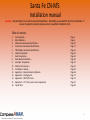
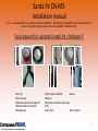
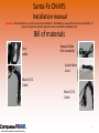
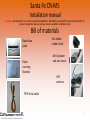
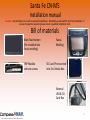
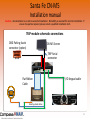
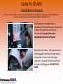
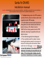
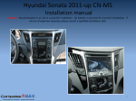
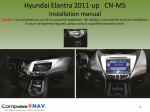
Santa Fe CN-M5 Installation manual Caution – Documentation is an aid to successful installation. No liability is assumed for incorrect installation. If unsure of expertise required, please consult a qualified installation tech. 2013 Santa Fe Base radio 2013 Santa Fe 4.3 Color Touchscreen 1 Santa Fe CN-M5 Installation manual Caution – Documentation is an aid to successful installation. No liability is assumed for incorrect installation. If unsure of expertise required, please consult a qualified installation tech. - Follow installation manual instructions carefully. Installer must careful to not cause interference between Navigator System c abling and active / passive car safety device (Ex: Air bags, seat belts, indicators, etc…) - Turn OFF the radio. - Before any attempt of component removal, the installer must disconnect the vehicle battery and isolate the ends of the cable . - Do not attempt this installation operation if there are missing components. Please check the bill of materials carefully to ens ure the kit is complete. - Installation requires careful attention. If you have concerns about your abilities to perform delicate operations, then do not b egin the installation. - The car must be secured to not move during installation. Parking brake must be engaged at all times. - Operation should be made in a clean, safe and well ventilated environment without trip hazards and slippery floors - Do not install by yourself if you do not have qualifications and/or tools to perform the retrofit. You may damage the car’s co mponents and/or the Navigator if not professionally installed. - Poor installation can result in poor performance, personal injuries and will immediately void the factory warranty. - Do not install the Navigator in a position that blocks the driver's view or hinders safe vehicle operation. 2 Santa Fe CN-M5 Installation manual Caution – Documentation is an aid to successful installation. No liability is assumed for incorrect installation. If unsure of expertise required, please consult a qualified installation tech. Caution Installation Time is around 3 hours with additional time required for options installation Do NOT RUSH and if issues occur contact technical support 3 Santa Fe CN-M5 Installation manual Caution – Documentation is an aid to successful installation. No liability is assumed for incorrect installation. If unsure of expertise required, please consult a qualified installation tech. Table of contents: 1. 2. 3. 4. 5. 6. 7. 8. 9. 10. 11. 12. 13. 14. 15. 16. Tools Required – Bill of Materials – Cables interconnection identification – Touchscreen Connections identification – TRIP Module connection identification – Vehicle Preparation – Radio Preparation – Radio Bracket Installation – Glove Box Preparation – Electrical Connections – Installation in Vehicle – Appendix 1 – Reverse Camera Installation Appendix 2 – Parking Assist Appendix 3 – RDS Traffic Tuner Appendix 4 – 4.3” factory color screen supplement Tips & Tricks Page 5 Page 6 Page 10 Page 17 Page 21 Page 24 Page 33 Page 45 Page 47 Page 51 Page 58 Page 68 Page 71 Page 74 Page 76 Page 83 4 Santa Fe CN-M5 Installation manual Caution – Documentation is an aid to successful installation. No liability is assumed for incorrect installation. If unsure of expertise required, please consult a qualified installation tech. Tools required for successful install -#1 = Patience!!! Vice Grip Electrical tape Philips #2 screwdriver magnetic Wide flat blade screwdriver Masking Tape Shop Towels & Alcohol Gloves Hacksaw 3M Industrial double sided tape Knife Side cutters Wire strippers 5 Santa Fe CN-M5 Installation manual Caution – Documentation is an aid to successful installation. No liability is assumed for incorrect installation. If unsure of expertise required, please consult a qualified installation tech. Bill of materials Aux cable Keypad Cable (Pre-installed) Audio Patch Cord Main I/O 1 Cable Main I/O 2 Cable 6 Santa Fe CN-M5 Installation manual Caution – Documentation is an aid to successful installation. No liability is assumed for incorrect installation. If unsure of expertise required, please consult a qualified installation tech. Bill of materials Radio face plate Radio securing Brackets Flat ribbon rubber block Mini Speaker and one screw GPS antenna TRIP Serial cable 7 Santa Fe CN-M5 Installation manual Caution – Documentation is an aid to successful installation. No liability is assumed for incorrect installation. If unsure of expertise required, please consult a qualified installation tech. Bill of materials Main Touchscreen (Pre-installed into Fascia molding) TRIP Module and two screws Fascia Molding SD Card (Pre-inserted into Ext. Media Box External USB & SD Card Box 8 Santa Fe CN-M5 Installation manual Caution – Documentation is an aid to successful installation. No liability is assumed for incorrect installation. If unsure of expertise required, please consult a qualified installation tech. Bill of materials Trip module Video & Signal cable T-Tap Terminal 9 Santa Fe CN-M5 Installation manual Caution – Documentation is an aid to successful installation. No liability is assumed for incorrect installation. If unsure of expertise required, please consult a qualified installation tech. Section 3 System Cable Connections and Identification 10 Santa Fe CN-M5 Installation manual Caution – Documentation is an aid to successful installation. No liability is assumed for incorrect installation. If unsure of expertise required, please consult a qualified installation tech. Rear Backup Camera Cable - Main I/O 1 Backup lamp +12V from Camera RED wire Ground GPS Antenna Connection – Main I/O 1 11 Santa Fe CN-M5 Installation manual Caution – Documentation is an aid to successful installation. No liability is assumed for incorrect installation. If unsure of expertise required, please consult a qualified installation tech. External Speaker Connection – Main I/O 1 TRIP Serial Cable connection: - 5 Pin to TRIP Module - 3 Pin(Yellow, Red and Black) to MAIN I/O 1 Trip Serial cable - 2 Pin(Blue and Green) to Audio Patch Cord 12 Santa Fe CN-M5 Installation manual Caution – Documentation is an aid to successful installation. No liability is assumed for incorrect installation. If unsure of expertise required, please consult a qualified installation tech. Aux Cable connection – Main I/O 1 To Audio Patch cord AUX IN (see next page) AV In connection – Main I/O 1 (Optional) Composite & stereo jacks DVD, Game console etc… 13 Santa Fe CN-M5 Installation manual Caution – Documentation is an aid to successful installation. No liability is assumed for incorrect installation. If unsure of expertise required, please consult a qualified installation tech. AUDIO SWITCHER Audio Patch Cord: - AUX IN (previous page) to Audio Switcher input jack. - Steering wheel control wires (2 pin from TRIP SERIAL Cable (P:7). 14 Santa Fe CN-M5 Installation manual Caution – Documentation is an aid to successful installation. No liability is assumed for incorrect installation. If unsure of expertise required, please consult a qualified installation tech. AV Out Connection – Main I/O 2 Rear seats Composite stereo jacks IR Sensor and Remote – Main I/O 2 (Optional) 15 Santa Fe CN-M5 Installation manual Caution – Documentation is an aid to successful installation. No liability is assumed for incorrect installation. If unsure of expertise required, please consult a qualified installation tech. Power connector for the CN-M5 Navigator coming from the Audio Patch cable 16 Santa Fe CN-M5 Installation manual Caution – Documentation is an aid to successful installation. No liability is assumed for incorrect installation. If unsure of expertise required, please consult a qualified installation tech. Section 4 Touchscreen Connection identification 17 Santa Fe CN-M5 Installation manual Caution – Documentation is an aid to successful installation. No liability is assumed for incorrect installation. If unsure of expertise required, please consult a qualified installation tech. Reserved for future use Main I/O 1 Main I/O 2 SD/USB connect Power Connection 18 Santa Fe CN-M5 Installation manual Caution – Documentation is an aid to successful installation. No liability is assumed for incorrect installation. If unsure of expertise required, please consult a qualified installation tech. SD/USB connection box to SD EXT connection SD/USB Interface Main I/O Connection #1 19 Santa Fe CN-M5 Installation manual Caution – Documentation is an aid to successful installation. No liability is assumed for incorrect installation. If unsure of expertise required, please consult a qualified installation tech. Main I/O Connection #2 Main Power Connection for Touchsreen 20 Santa Fe CN-M5 Installation manual Caution – Documentation is an aid to successful installation. No liability is assumed for incorrect installation. If unsure of expertise required, please consult a qualified installation tech. Section 5 Trip Module Connections and port identity 21 Santa Fe CN-M5 Installation manual Caution – Documentation is an aid to successful installation. No liability is assumed for incorrect installation. If unsure of expertise required, please consult a qualified installation tech. Trip Module Connections/Cable identification TRIP serial and steering wire connections Ribbon Connector Keypad Connection OBDII Parking Assist cable (Option) 22 Santa Fe CN-M5 Installation manual Caution – Documentation is an aid to successful installation. No liability is assumed for incorrect installation. If unsure of expertise required, please consult a qualified installation tech. TRIP module schematic connections OBD Parking Assist connector (option) CN-M5 Screen TRIP Serial connector Flat Ribbon Cable I/O Keypad cable Steering wheel cables 23 Santa Fe CN-M5 Installation manual Caution – Documentation is an aid to successful installation. No liability is assumed for incorrect installation. If unsure of expertise required, please consult a qualified installation tech. Section 6 Vehicle Preparation 24 Santa Fe CN-M5 Installation manual Caution – Documentation is an aid to successful installation. No liability is assumed for incorrect installation. If unsure of expertise required, please consult a qualified installation tech. Protect the vents surrounding area with masking tape to prevent surface damage as shown. 25 Santa Fe CN-M5 Installation manual Caution – Documentation is an aid to successful installation. No liability is assumed for incorrect installation. If unsure of expertise required, please consult a qualified installation tech. Carefully pry away the vent towards you starting at the bottom of the vent to gain enough to begin removing by hand. Store the vents pieces carefully to avoid damage. Repeat the process for the other side. 26 Santa Fe CN-M5 Installation manual Caution – Documentation is an aid to successful installation. No liability is assumed for incorrect installation. If unsure of expertise required, please consult a qualified installation tech. Once both vents are removed , the radio securing screws are exposed. Remove both screws and reserve. Repeat on the other side. 27 Santa Fe CN-M5 Installation manual Caution – Documentation is an aid to successful installation. No liability is assumed for incorrect installation. If unsure of expertise required, please consult a qualified installation tech. Gently ease the radio forward to expose the rear. 28 Santa Fe CN-M5 Installation manual Caution – Documentation is an aid to successful installation. No liability is assumed for incorrect installation. If unsure of expertise required, please consult a qualified installation tech. Disconnect the FM and XM antenna from the rear of the radio. Caution, press the locking tab after the pink plastic to disengage the XM antenna. A little flat screw driver may help. XM FM Santa Fe base model radio shown To free the radio completely disconnect the 2 multi-way connectors on the rear of the radio. Pressing the locking tab down allows the connectors to be removed from the back. (1 additional multi-way connector to remove for the 4.3 Color touchscreen) 29 Santa Fe CN-M5 Installation manual Caution – Documentation is an aid to successful installation. No liability is assumed for incorrect installation. If unsure of expertise required, please consult a qualified installation tech. The red lines identify the area that needs to be trimmed. The factory radio will be located deeper in the dash than before to accommodate the new touchscreen and bezel mount. Be careful to not cut electrical wires!!!! Using a small saw (or any appropriate tool) trim the area marked to reflect the next step. This is necessary to allow the updated radio to be installed correctly. Clean the entire area with a vacuum to remove the plastic debris. 30 Santa Fe CN-M5 Installation manual Caution – Documentation is an aid to successful installation. No liability is assumed for incorrect installation. If unsure of expertise required, please consult a qualified installation tech. Bend all the way down the radio supporting bracket as shown. Doing this ensures enough clearance to position the cables under the radio at final assembly. 31 Santa Fe CN-M5 Installation manual Caution – Documentation is an aid to successful installation. No liability is assumed for incorrect installation. If unsure of expertise required, please consult a qualified installation tech. Remove the securing clip from the car harness. Doing this will ensure enough clearance at the back of the radio at final assembly. 32 Santa Fe CN-M5 Installation manual Caution – Documentation is an aid to successful installation. No liability is assumed for incorrect installation. If unsure of expertise required, please consult a qualified installation tech. Section 7 Radio Preparation 33 Santa Fe CN-M5 Installation manual Caution – Documentation is an aid to successful installation. No liability is assumed for incorrect installation. If unsure of expertise required, please consult a qualified installation tech. Remove existing retaining brackets using a Phillips head screwdriver. Secure the 4 screws removed. 34 Santa Fe CN-M5 Installation manual Caution – Documentation is an aid to successful installation. No liability is assumed for incorrect installation. If unsure of expertise required, please consult a qualified installation tech. Remove the 6 front panel retaining screw as shown. (2 opposite side) To detach the front panel completely from the radio, there are 8 retaining tabs that retain the radio panel in ( 2 on bottom, 2 on top and 2 either side) . GENTLY lift these up a little (DO NOT SNAP THEM OFF) and pry the radio fascia clear enough to allow access to the cables on the rear. A second flat screw driver might help to keep the clips released while unclipping others. 35 Santa Fe CN-M5 Installation manual Caution – Documentation is an aid to successful installation. No liability is assumed for incorrect installation. If unsure of expertise required, please consult a qualified installation tech. Once the panel is free of the chassis, we need to remove the ribbon cable. Notice the ribbon cable connection. There are locking tab cutouts on the ribbon cable to ensure the cable stays in place. 36 Santa Fe CN-M5 Installation manual Caution – Documentation is an aid to successful installation. No liability is assumed for incorrect installation. If unsure of expertise required, please consult a qualified installation tech. A little pressure is needed from a screwdriver to lift up the brown locking tab to allow the connector to freely be disconnected. Be gentle to avoid damaging the brown locking tab Notice the red circles. The cable needs to be disengaged from the unlocked brown locking tab, to free it from the beige connector. Separate the white end from the lock by lifting gently. DO NOT PULL HARD 37 Santa Fe CN-M5 Installation manual Caution – Documentation is an aid to successful installation. No liability is assumed for incorrect installation. If unsure of expertise required, please consult a qualified installation tech. Once the cable disengages from the brown locking tabs gently remove the ribbon cable from the beige connector Ribbon Cable disconnected – AT LAST! 38 Santa Fe CN-M5 Installation manual Caution – Documentation is an aid to successful installation. No liability is assumed for incorrect installation. If unsure of expertise required, please consult a qualified installation tech. Remove the 2 screws holding the CD player as indicated here and save these separately because they are smaller. Then remove the 5 screw surrounding the face plate 39 Santa Fe CN-M5 Installation manual Caution – Documentation is an aid to successful installation. No liability is assumed for incorrect installation. If unsure of expertise required, please consult a qualified installation tech. Assemble the trip module with the supplied screws as indicated. The connectors must face the face plate with the flat ribbon connector located at the left TRIP module correctly installed 40 Santa Fe CN-M5 Installation manual Caution – Documentation is an aid to successful installation. No liability is assumed for incorrect installation. If unsure of expertise required, please consult a qualified installation tech. Run the flat ribbon thru the new face plate carefully. Make sure not bend the flat ribbon. Then assemble the new face plate and locate it using the embosses circled. Screw (3) the face plate starting by the opposite corners to make sure the radio body is square. Place a screw as shown, this will be use to ground the CN-M5 reverse camera circuit. Screw the CD player at the top of the slots as shown using the small screws reserved separately. Proceed with the flat ribbon install Next page… 41 Santa Fe CN-M5 Installation manual Caution – Documentation is an aid to successful installation. No liability is assumed for incorrect installation. If unsure of expertise required, please consult a qualified installation tech. 1 3 2 2 1- The black locking tab in the TRIP module is carefully lifted to allow the ribbon cable to be installed into the TRIP module. 2- The flat ribbon contacts (silver) need to be facing down (to make contact) and the blue needs to face up. The ribbon must be CAREFULLY but firmly pushed into the TRIP connector, ensuring it is parallel and has no bends or tears. 3- Then fold down gently the locking tab. 4- Then carefully install the rubber retainer, inserting the bottom piece first into place to ensure the locking tab and therefore ribbon cable does not disengage. Caution: Make sure to insert the bottom of the rubber block first otherwise the locking tab may fold back and brake. If the locking tab is broken; stop the 42 installation immediately and contact support. Santa Fe CN-M5 Installation manual Caution – Documentation is an aid to successful installation. No liability is assumed for incorrect installation. If unsure of expertise required, please consult a qualified installation tech. The protruding curve of the ribbon cable must be CAREFULLY eased back into the radio unit (under the TRIP module), use just enough pressure to push into the radio. Completed TRIP module ribbon cable installation. 43 Santa Fe CN-M5 Installation manual Caution – Documentation is an aid to successful installation. No liability is assumed for incorrect installation. If unsure of expertise required, please consult a qualified installation tech. You have successfully retrofitted your factory radio! 44 Santa Fe CN-M5 Installation manual Caution – Documentation is an aid to successful installation. No liability is assumed for incorrect installation. If unsure of expertise required, please consult a qualified installation tech. Section 8 Radio Bracket installation 45 Santa Fe CN-M5 Installation manual Caution – Documentation is an aid to successful installation. No liability is assumed for incorrect installation. If unsure of expertise required, please consult a qualified installation tech. TOP Attach the dash mounting brackets to the side of the radio using the 2 mounting points. Alignment the bracket in dimple (GREEN circle) to locate the brackets correctly. These are supplied in the installation kit. NOTE – Look at the orientation of the brackets, the cut off check and corner radio are at the top of radio. Repeat for the other side of the radio. You have successfully prepared your radio. 46 Santa Fe CN-M5 Installation manual Caution – Documentation is an aid to successful installation. No liability is assumed for incorrect installation. If unsure of expertise required, please consult a qualified installation tech. Section 9 Glove Box Preparation 47 Santa Fe CN-M5 Installation manual Caution – Documentation is an aid to successful installation. No liability is assumed for incorrect installation. If unsure of expertise required, please consult a qualified installation tech. Open the glove box and rotate the guides (1) and remove them. Disconnect the cylinder (2) to completely release the glove box. 1 2 48 Santa Fe CN-M5 Installation manual Caution – Documentation is an aid to successful installation. No liability is assumed for incorrect installation. If unsure of expertise required, please consult a qualified installation tech. Apply 2 strips of double sided tape at the back of the external media box as shown or use the supplied screws. 49 Santa Fe CN-M5 Installation manual Caution – Documentation is an aid to successful installation. No liability is assumed for incorrect installation. If unsure of expertise required, please consult a qualified installation tech. Route the External Media Storage connector under the radio location. Peel the red tape from the double face tape and affix as shown. Affix the Media box against the left inner wall and 2” from the face as shown. Secure the storage cord beside the air filter box. Trim the top of the glove box to clear the Storage box IF NEEDED. 50 Santa Fe CN-M5 Installation manual Caution – Documentation is an aid to successful installation. No liability is assumed for incorrect installation. If unsure of expertise required, please consult a qualified installation tech. Section 10 Electrical/Wiring Connections 51 Santa Fe CN-M5 Installation manual Caution – Documentation is an aid to successful installation. No liability is assumed for incorrect installation. If unsure of expertise required, please consult a qualified installation tech. In the following section we will: - Prepare the Audio Patch Cord for the final assembly - Attach the Audio Patch Cord to the car & radio connectors - Parts Required: - Video Tutorial about this section: https://dl.dropboxusercontent.com/u/70065767/Manuals/Audio%20Patch%20Cord%20Assy.m2ts Aux cable Audio Patch Cord TRIP Serial cable 52 Santa Fe CN-M5 Installation manual Caution – Documentation is an aid to successful installation. No liability is assumed for incorrect installation. If unsure of expertise required, please consult a qualified installation tech. Attach the TRIP Serial cable 2 Pin connector to this connector to the Audio Patch cord as shown. TRIP Serial cable 53 Santa Fe CN-M5 Installation manual Caution – Documentation is an aid to successful installation. No liability is assumed for incorrect installation. If unsure of expertise required, please consult a qualified installation tech. Attach the AUX cable male jack into the female of the Aux switcher board as shown. Secure in place with Electrical tape. Reserve the White and RED RCA jack to be connected into the AUX cable from the MAIN I/O 1 Aux cable 54 Santa Fe CN-M5 Installation manual Caution – Documentation is an aid to successful installation. No liability is assumed for incorrect installation. If unsure of expertise required, please consult a qualified installation tech. Connect the Audio Patch cord to the car matching connector as shown. Connectors improperly seated. Connectors properly seated. You should hear a CLICK. 55 Santa Fe CN-M5 Installation manual Caution – Documentation is an aid to successful installation. No liability is assumed for incorrect installation. If unsure of expertise required, please consult a qualified installation tech. Reserve the CN-M5 4 pins square connector for the final assembly. Attach the TRIP SERIAL to the MAIN I/O 1 TRIP SERIAL. (Ref: P:11) Reserve the TRIP MOD cable for the final assembly. It will be plugged in front of the trip module (Ref: P:11) 56 Santa Fe CN-M5 Installation manual Caution – Documentation is an aid to successful installation. No liability is assumed for incorrect installation. If unsure of expertise required, please consult a qualified installation tech. Mini speaker installation The recommended placement of the mini-speaker is located on the driver side. Air vent Using the provided screw, attach the mini speaker to the side kick panel as shown. The speaker is very light and require only one screw. Once completed, bring the wire to the head unit for final install. Driver side kick panel 57 Santa Fe CN-M5 Installation manual Caution – Documentation is an aid to successful installation. No liability is assumed for incorrect installation. If unsure of expertise required, please consult a qualified installation tech. Section 11 Installation into Vehicle 58 Santa Fe CN-M5 Installation manual Caution – Documentation is an aid to successful installation. No liability is assumed for incorrect installation. If unsure of expertise required, please consult a qualified installation tech. Location of GPS antenna in the dashboard Using 3M tape attach the GPS antenna above the air duct underneath the dashboard surface. “GPS” letters of the antenna should be towards the sky. Testing has shown that signal is very good at this point. Route the GPS cable under the radio area clearing the right air opening 59 Santa Fe CN-M5 Installation manual Caution – Documentation is an aid to successful installation. No liability is assumed for incorrect installation. If unsure of expertise required, please consult a qualified installation tech. IMPORTANT Before proceeding to the final installation if you have purchased the following options, please proceed to their installation before completing the final assembly. - Backup Camera - Parking Assist System - RDS Traffic Tuner Appendix 1 page 66 (Santa Fe 4.3 not applicable) Appendix 2 page 69 (Santa Fe 4.3 not applicable) Appendix 3 page 72 60 Santa Fe CN-M5 Installation manual Caution – Documentation is an aid to successful installation. No liability is assumed for incorrect installation. If unsure of expertise required, please consult a qualified installation tech. Prior the assembly of the trim to the car, please make sure you have at least the following connected properly . - GPS Antenna to GPS Serial of MAIN I/O 1 TRIP cable to TRIP Serial of MAIN I/O 1 Mini Speaker to SPK of MAIN I/O 1 AUX cable to AUX of MAIN I/O 1 - OPTIONS: CAMERA to CAMERA of MAIN I/O 1 Audio Video Extension cord to AVIN of MAIN I/O 1 for external multimedia player Audio Video Extension cord to AVOUT of MAIN I/O 2 for read seat screen and sound IR Receiver for Infrared remote of MAIN I/O 2 TMC cable to TMC Traffic receiver of MAIN I/O 2 61 Santa Fe CN-M5 Installation manual Caution – Documentation is an aid to successful installation. No liability is assumed for incorrect installation. If unsure of expertise required, please consult a qualified installation tech. After ensure all cables are correctly brought through to area beneath radio, attach: - Radio antenna - XM antenna - Factory reverse camera - Multi-way connectors (2) - Audio Patch cord goes into the first spot. And install radio in dashboard. If the radio does not fit well in place, make sure there is no unnecessary cables behind it and ensure they are well placed under the radio. Affix using the screws removed earlier. 62 Santa Fe CN-M5 Installation manual Caution – Documentation is an aid to successful installation. No liability is assumed for incorrect installation. If unsure of expertise required, please consult a qualified installation tech. Prior installing the fascia, connect the TRIP cable to the TRIP module as indicated (5 PINS) and Parking Assist System cable (3 PINS) if purchased. Getting ready to attach the new fascia trim, connect: - Keypad green cable to the TRIP module. - External media box (SD Card/USB) Main I/O 1 Main I/O 2 (If needed) CN-M5 Power (4 PINS square) 63 Santa Fe CN-M5 Installation manual Caution – Documentation is an aid to successful installation. No liability is assumed for incorrect installation. If unsure of expertise required, please consult a qualified installation tech. Install the facia temporarily in place and plug back the wires to the battery and test run the CN-M5 navigator. Prior final assembly, test the following: - Radio mode (TRIP): FM, XM, USB, AUX, CD Steering Wheel Controls and Voice Commands, etc… ALL functions supported by the factory radio. - Facia keypad - Navigation: Check for GPS reception (at least configure the basic settings on start-up) - MP3 Player: See if you can select music from the File folder (refer to User Manual. Connect a USB thumb drive to the External Media box prior testing) Once completed, you can proceed with the final assembly. Put back the remaining trim pieces. 64 Santa Fe CN-M5 Installation manual Caution – Documentation is an aid to successful installation. No liability is assumed for incorrect installation. If unsure of expertise required, please consult a qualified installation tech. For proper radio operation, the correct car type needs to be selected. Go into the CN-M5 Setting Panel, Select TRIP and at the bottom change accordingly as below. Failing to do this may result into a TRIP.DLL FAILED TO LOAD message. 2013+ : Santa Fe – CAR TYPE 26 2013+ 4.3 Color Touchscreen: Santa Fe – CAR TYPE 30 65 Santa Fe CN-M5 Installation manual Caution – Documentation is an aid to successful installation. No liability is assumed for incorrect installation. If unsure of expertise required, please consult a qualified installation tech. YOU DID IT! 66 Santa Fe CN-M5 Installation manual Caution – Documentation is an aid to successful installation. No liability is assumed for incorrect installation. If unsure of expertise required, please consult a qualified installation tech. Page Intentionally Blank 67 Santa Fe CN-M5 Installation manual Caution – Documentation is an aid to successful installation. No liability is assumed for incorrect installation. If unsure of expertise required, please consult a qualified installation tech. Appendix 1 Reverse Camera Installation 68 Santa Fe CN-M5 Installation manual Caution – Documentation is an aid to successful installation. No liability is assumed for incorrect installation. If unsure of expertise required, please consult a qualified installation tech. Appendix 2: Backup Camera install Attach the BLACK wire from MAIN I/O 1 “REAR PWR” to the radio front bottom screw as shown (Ground) . 69 Santa Fe CN-M5 Installation manual Caution – Documentation is an aid to successful installation. No liability is assumed for incorrect installation. If unsure of expertise required, please consult a qualified installation tech. Attach the RED wire from MAIN I/O 1 “REAR PWR” to the backup camera RED wire. Plug the back up camera RCA jack into the same Yellow Camera jack of MAIN 1/O 1 70 Santa Fe CN-M5 Installation manual Caution – Documentation is an aid to successful installation. No liability is assumed for incorrect installation. If unsure of expertise required, please consult a qualified installation tech. Appendix 2 Parking Assist 71 Santa Fe CN-M5 Installation manual Caution – Documentation is an aid to successful installation. No liability is assumed for incorrect installation. If unsure of expertise required, please consult a qualified installation tech. Appendix 3: Parking Assist System Connection of the Parking Assist System is OBD II Connector very simple. Insert into the “CAN” Position Plug the other end into the Trip Module as shown 72 Santa Fe CN-M5 Installation manual Caution – Documentation is an aid to successful installation. No liability is assumed for incorrect installation. If unsure of expertise required, please consult a qualified installation tech. Plug the Parking Assist connector into the car’s OBD located right underneath the driver crash pad in the middle. Once inserted, lock it in place by moving the yellow tab until you hear a “click”. Note: Please advise your dealer about this sensor and how to proceed to remove it. 73 Santa Fe CN-M5 Installation manual Caution – Documentation is an aid to successful installation. No liability is assumed for incorrect installation. If unsure of expertise required, please consult a qualified installation tech. Appendix 3 RDS Traffic Tuner 74 Santa Fe CN-M5 Installation manual Caution – Documentation is an aid to successful installation. No liability is assumed for incorrect installation. If unsure of expertise required, please consult a qualified installation tech. Connect the female TMC FM adapter to the car male. FM RDS TMC Connect the male TMC FM adapter to the back of the radio. Reserve the white connector MAIN I/O 2 for the final assembly. 75 Santa Fe CN-M5 Installation manual Caution – Documentation is an aid to successful installation. No liability is assumed for incorrect installation. If unsure of expertise required, please consult a qualified installation tech. Appendix 4 4.3” factory color touchscreen supplement 76 Santa Fe CN-M5 Installation manual Caution – Documentation is an aid to successful installation. No liability is assumed for incorrect installation. If unsure of expertise required, please consult a qualified installation tech. 1- Prior Installing the trip module into the radio chassis, connect the trip module video & signal cable at the back of the trip module as shown. Then guide the trip module inside the radio body, make sure all the wires are directed to the front of the radio chassis. See bill of material 2- Locate the wire labeled GND from the wires brought to the front; make a loop and attach the terminal to the lower right corner of the radio chassis using one of the screws removed from the factory faceplate. Once this step completed, return to the section you came from. 77 Santa Fe CN-M5 Installation manual Caution – Documentation is an aid to successful installation. No liability is assumed for incorrect installation. If unsure of expertise required, please consult a qualified installation tech. To ease your work, have the radio body sitting on the dashboard surface on top of the radio opening. Avoid surface damage by laying down a protective layer under the radio body! Locate the Red wire with Black stripes at the location shown. Engage the wire into the T-TAP terminal slit then fold the TTAP lower jaw until it “clicks”. Proceed with the next page… 78 Santa Fe CN-M5 Installation manual Caution – Documentation is an aid to successful installation. No liability is assumed for incorrect installation. If unsure of expertise required, please consult a qualified installation tech. Locate the Orange wire coming out from the radio labeled R. CAM12V IN and insert the flat terminal into the T-TAP terminal all the way in. Now the trip module will sense the reverse gear position and will manage the backup view Once this step completed, return to the section you came from. You can proceed with the radio install into the dashboad. 79 Santa Fe CN-M5 Installation manual Caution – Documentation is an aid to successful installation. No liability is assumed for incorrect installation. If unsure of expertise required, please consult a qualified installation tech. Locate the male Yellow RCA labeled R.CAM OUT from the radio body and plug into the MAIN I/O 1 REAR CAM cable. Secure with electrical tape. Locate the Red wire labeled R.CAM 12V OUT coming out from the radio and plug into the RED male bullet terminal of the MAIN I/O 1 labeled REAR PWR. 80 Santa Fe CN-M5 Installation manual Caution – Documentation is an aid to successful installation. No liability is assumed for incorrect installation. If unsure of expertise required, please consult a qualified installation tech. Locate the BLACK wired terminal of the MAIN I/O 1 labeled REAR PWR and attach the terminal to the lower middle threaded hole of the radio chassis using one of the screws removed from the factory faceplate. Once this step completed, return to the section you came from. You almost done with your install! 81 Santa Fe CN-M5 Installation manual Caution – Documentation is an aid to successful installation. No liability is assumed for incorrect installation. If unsure of expertise required, please consult a qualified installation tech. Tips and tricks To avoid over heating wire and connectors, it is recommended you use soldering acid Flux. This will greatly improve the quality of the soldering points. Before soldering, dip Into the acid flux paste the end of the soldering rod and apply a little flux to the wire section you wish to solder. 82 Santa Fe CN-M5 Installation manual Caution – Documentation is an aid to successful installation. No liability is assumed for incorrect installation. If unsure of expertise required, please consult a qualified installation tech. END 83