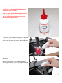
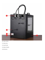
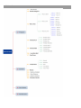
1
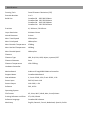
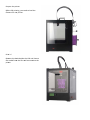
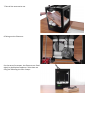
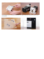
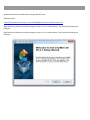
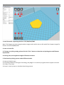
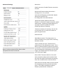
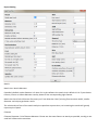
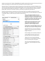
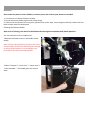
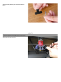
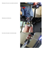
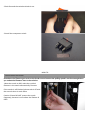
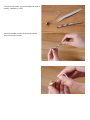
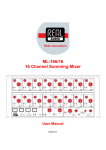
 US
SER MA
ANU
UAL
V
V1.0
0
Saafety G
GROUND CO
ONNECTION
N CAUTION: M
C
Make sure thhe power grrounded, if not, may caause the accumulation
n of static‐electricity so as too damage e
electronic syystem. HEAT WARN
H
NING: Creat Bot 3D Printer generattes high tem
mperatures and includees m
moving part
ts that can ccause injuryy. Please Ne
ever Touch tthe nozzle, the heated a
aluminium b
block or thee build plate
e after preheating or prrinting to avvoid scaldin
ng. CAUTION: Do not leavee the printerr attended ffor a long tiime during printing. If yyou C
h
have to do s
so, do follow
w these guid
dance: •• Ensure thaat the first laayer of the print is properly land oon the build
d plate. •
• Ensure fila
ament wounnd on the sp
pool to keep feeding sm
moothly, in case of tangles. •
• Monitor yo
our print peeriodically.
CAUTION: The melt fila ment will e
C
emit the plastic odour dduring printting. Please k
keep ventila
ation in the work place. CAUTION: In
C
n case of em
mergency disconnect power supplyy from wall socket. COMPLIANC
C
CE: Your CreeatBot has b
been tested strictly by SGS with th
he permissio
on o
of FCC, CE, I
C, C‐Tick annd ROHS. Itt complies w
with the rul es and limitts of EMC, M
MD and RO HS, to provide reasonable p
protection aagainst harm
m to the hu
uman, from electromaggnetic c
compatibilit
y, mechaniccal structurre and chem
mical compoonent. Specifications Forming Tech. Fused Filament Fabrication (FFF) Extruder Number 1 or 2 Build Size CreatBot DS 200*200*250mm CreatBot DM 250*250*300mm CreatBot DX 300*250*300mm CreatBot DH 250*250*450mm Precision X,Y 0.01mm, Z 0.015mm Layer Resolution 0.04mm‐0.4mm Nozzle Diameter 0.4mm Max. Travel Speed 250mm/sec. Max. Print Speed 180mm/sec. Max. Extruder Temperature 270Deg. Max. Hot Bed Temperature 105Deg. Max. Extrude Speed 100mm/sec Filament Filament Type ABS, PLA, PVA, HIPS, Nylon, Laywood, PET Filament Diameter 3mm Filament Temperature 150~270Deg. Hardware Controller Mother Board Arduino ATmega2560 R3Micro Controller Stepper Motor CreatBot Main Board Geared Motor X, Y axis 42*48, 1.3A; Z axis 42*63, 1.5A Power Input E42*42, Ratio 1:10 Power Output 110~220V, 1.5A Software 24V, 10.5A Operating System File Format XP, Vista, Win7, Win8, Mac, Linux/Unbutu Printing Software and Slicer STL, OBJ, GCode Software Language CreatBot 3D Software Machinery English, Deutsch, French, Nederland, Spanish, Polish How
w it Works The CreatBot3D
D Printer m
makes solid, three‐dimeensional objects out of melted fila ment. Yourr 3D designed files aare translated into insttructions fo r the CreatB
Bot and read by the maachine via SSD card. Thee CreaatBot then heats the fiilament and
d squeezes iit out throu
ugh a nozzle
e onto a heaated surface
e to build a solid
d object, layyer by layerr. This meth
hod is calledd Fused Filament Fabriccation [FFF]]. Pre
eparing the model Use
e a 3D modeeling prograam to creat a 3D model and exp
port the filee as a stl or o
obj form
mat 3D mod
del Cre
eatBot 3D So
oftware Ope
en the CreaatBot 3D Sofftware. Imp
port the CAD
D file into th
he CreatBott 3D Softwaare and pre
epare the gccode file forr your CreattBot 3D Prin
nter. Note tthat other M
Marlin based
d softtware packaages may also be used if pre
eferred. In tthe CreatBo
ot 3D Softwaare , you can set prin
nting param
meters for your model, such as laye
er thicknesss, printing sspeed and n
nozzle tem
mperature, tthen outputt a gcode file for prin
nting. Transfer the GCode file Savve the GCod
de file into tthe SD card,, and inse
ert it into th
he SD card rreader of th
he prin
nter. Pre
epare the prrinter Beffore 3D prin
nting, you need to load the filament for th
he printer. Prin
nt it! Ope
erate the kn
nob beside the LCD and choose the
e model from
m the SD caard inserted
d into the prin
nter Unpacking 1 Place the CreatBot 3D Printer on the floor. Leave enough available space for unpacking 2 Your CreatBot 3D Printer is packed with multiply carton, cardboard, foam and sealed bag to ensure the machine to your hands in perfect status. 3 Remove the first cardboard layer. Ensure that the printer is the right way up. Open the plastic bag. 4 Now it’s time to take out your CreatBot 3D Printer from the box. Lift it out by grasping the frame.(not the belts or rails) firmly but gently at the left① and right ② of the 3D Printer. 5 Place the CreatBot 3D Printer on the floor. Leave enough available space for unpacking Caution: Be careful NOT to grip the belt or shaft of the motion system. 6 Remove the stretch film around the 3D printer. You can see all the accessories, tools and filaments. 7 Take all the accessories out. 8 Taking out the filaments: For the ease of transport, the filaments are fixed tightly by build plate supporter. Take them out using the following the next 3 steps: 1) Connect power cable to printer 2) Turn on the printer. 3) Go to the LCD menu: "Prepare > Autohome", and the two holders will go to the top of Z axis. 4)Take out the two spools of PLA filament and the two feeding devices. Accessories Taking out accessories, tool box and filament and check if below things are included: 1) 2 x spools of PLA filament,diameter 3mm,1kg/spool; 2) 1 x Build platform: It is packed in the white EPE. 3) 1 tool box:including the necessary tools for installation and other accessories. 4) 2 feeding devices:constituted by gear motor and feeder with the advantages of high accuracy and easy to operate. 5) 3 x enclosure covers: installed on 3 sides (front, left, right) to keep the temperature constant inside printing space. Setting Up Your CreatBot 3D Printer A‐ Install the Handles 1). Locate the four holes are on the top of the printer. These are used to mount the handles. 2).You will need a screwdriver, four screws and two the two handles. 3).Use the screwdriver to fix the two holders on left and right of the printer top side. Note: Please ensure that you have tightened the nut sufficiently. Use a spanner to hold the nut in place when tightening. 4).Handle installation complete. B‐ Install the Build Platform 1).Turn on your printer, enter “Prepare > Move axis > Move 1mm> Move Z”, lowering Z axis a little (for example 30mm) to avoid collision between nozzle and build platform while installation. Check to ensure that the bars (shown) are both at both parallel to each other and at 90 degrees to the back plate 2).Insert the platform’s holder into the middle of platform. Slide in the platform from the front of the machine. Note: The end of platform with black connection wire should toward the printer 3).Take out the nuts and screwdriver from the tool box to fix the platform and platform holder firmly. Note: After installing the platform installation, please tighten the four black screws a little bit more under the build plate to lower it to avoid knocking the extruders in next operation. 4).Connect the power wire and data cable of platform with the connectors. Caution: Make sure the plugs are fully connected. Otherwise the platform may not heat or may over heat. C‐ Feeding Device Installation 1).Mount Feeding motor: using small wrench to fix No. 1 feeding motor on position 1. 2).Insert the end of feeding tube into the socket of feeding motor and tighten firmly. 3).Connect the data cable with feeding devices. 4).Feeding device installation done. D Filament Spool Holder Installation 1).Take the two spool holders out of the tool box.
2).Install filament spool’s holders into the two threaded holes at the rear of the machine.. E Lubricate the Guide Rails The guide rails may be dry when you receive your printer, so check and lubricate the guide rails before your first print. Only use a high quality thin sewing machine oil such as Singer Oil (the product shown here). The use of incorrect lubricant may cause the bearings to dry up and cease. 1).The cross rails have ball bearings inside and only require very little lubrication. Lubricate the two cross guide rails with only a small dab of lubricant.
2).Lubricate the four guide rails around the printer framework. Notice: Lubrication is very important for good printing performance, or else you might encounter printhead stuck problem. 1. SD‐card slot 6. Print head 2. Push and rotate button 7. Filament guide tube 3. Display 8. Printer holder 4. Build plate screws 9. Power switch 5.Build plate 10. Power Socket 11. Name plate 12. Spool holder 13. Material feeder 14.USB Socket LCD Menu Structure LCD Menu Press the knob to enter the menu: 1 ‐ Prepare: The printer enters ready state 1.1 ‐ Auto home The printer returns to original state ( In X.Y direction, the extruder returns the left bottom in top view; In Z direction, the build plate returns to top position) 1.3 ‐ Move axis: Move 10mm: Move 10mm each step Move X: Move 10mm each step in X direction Move Y: Move 10mm each step in Y direction Move 1mm: Move 1mm each step Move X: The extruder will move 10mm each step in X direction Move Y: The extruder will move 10mm each step in Y direction Move Z: The build plate will move 10mm each step in Y direction Extruder: The feeding motor of left nozzle will extrude the filament in each step of 1mm Extruder2: The feeding motor of right nozzle will extrude the filament in each step of 1mm Move 0.1mm: Move 0.1mm each step Move X: The extruder will move 0.1mm each step in X direction Move Y: The extruder will move 0.1mm each step in Y direction Move Z: The build plate will move 0.1mm each step in Y direction Extruder: The feeding motor of left nozzle will extrude the filament in each step of 0.1mm Extruder2: The feeding motor of right nozzle will extrude the filament in each step of 0.1mm 1.4 ‐ Preheat PLA: Preheat PLA1: Preheat extruder and build plate to the working temperature of PLA required ( Default: Extruder, 215 , Build plate, 45 ) Preheat PLA2: Preheat extruder 2 and Build plate to the working temperature of PLA required ( Default: Extruder, 215 ; Build plate, 45 ) Preheat PLA All: Preheat two extruders both and build plate to the working temperature of PLA required ( Default: Extruder, 215 ; Build plate, 45 ) Preheat PLA Bed: Preheat build plate to the working temperature of PLA required ( Default: Build plate, 45
) 1.5 ‐ Preheat ABS: Preheat ABS1: Preheat extruder and build plate to the working temperature of ABS required ( Default: Extruder, 255 ; build plate, 45 ) Preheat ABS2: Preheat extruder 2 and build plate to the working temperature of ABS required ( Default: Extruder, 255 ; Build plate, 45 ) Preheat ABS All: Preheat two extruders both and build plate to the working temperature of ABS required ( Default: Extruder, 255 ; Build plate, 45 ) Preheat ABS Bed: Preheat build plate to the working temperature of ABS required ( Default: Build plate, 45
). 1.6 ‐ Leveling Bed: Build plate calibration assist‐function. Rotate the button, the extruder will move to next position in clockwise direction in top view. 1.7 ‐ Cool down: Cool down the extruder and build plate to normal temperature. 2 ‐ Control: Adjust printer settings 2.1 ‐ Temperature: Nozzle: Left temperature setup Nozzle 2: Right temperature setup Bed: build plate setup Fan speed: Cooling fan speed setup Auto Temp: All the above data setup automatically 2.2 ‐ Motion: Please do NOT change any data in this menu if without specialist experience. Accel: Accelerated speed of extruder motion Vmax x: Max speed in X direction Vmax y: Max speed in Y direction Vmax z: Max speed in Z direction Vmax e: Max speed of feeding motor Vmin: Min printing speed VTrav min: Min travel speed Amax x: Max accelerated speed in X direction Amax y: Max accelerated speed in Y direction Amax z: Max accelerated speed in Z direction Amax e: Max accelerated speed of feeding motor A‐retract: Accelerated speed of retract Xsteps/mm: Transmission ratio of X motor Ysteps/mm: Transmission ratio of Y motor Zsteps/mm: Transmission ratio of Z motor Esteps/mm: Transmission ratio of feeding motor 2.3 ‐ Restore Failsafe: Please do NOT change any data setting here in this menu. 2.4 ‐ Save memory: Record the coordinate of printing stop 2.5 ‐ Restore factory: Restore the manufacturer default settings 2.6 ‐ Firmware version: Current firmware version Menus in Printing Process During the printing, you can press the knob to change some printing settings. 1. Tune: Re‐set some parameters ‐ F/R: the actual printing speed takes the percentage of the pre‐set speed in the software. It can be adjusted while printing according to the actual situation. ‐ Nozzle: Temperature setup of left nozzle ‐ Nozzle 2: Temperature setup of right nozzle ‐ Bed: Temperature setup of build plate ‐ Fan speed: Fan speed setup ‐ Flow: Filament feeding flow rate ‐ Flow 0: Filament feeding flow rate of left nozzle ‐ Flow 1: Filament feeding flow rate of right nozzle ‐ Auto Temp: Set all the above temperature automatically ‐ Change filament: To stop the printing and change the filament. It will record the printing stop position so as to continue to print after filament changing. 2. Control: Please do NOT change any data in this menu if without specialist experience. 3. Pause: To stop the printing, but it will record the printing stop position to continue the printing. 4. Stop Print: To finish the printing job Software Download and Install Download the latest CreatBot 3D Printing Software here‐ Windows users‐ https://dl.dropboxusercontent.com/u/12996808/Software/CreatBot_Setup.msi Right click the software installation program, select "run as administrator" and install it following the prompts. Right click the software installation program, select "run as administrator" and install it following the prompts. Interface 1. Load 3D model, supporting the files of STL/OBJ/DAE/AMF. Note: The Program can also recognize planar images, and transfer them to 3D model files. Support image file formats include JPG/BMP/PNG. 2. Save as Gcode file 3. If change any slicing setting, please click this "Slice" button to show the real printing time and filament requirement. 4. Printing time, the length and weight of filament consume. 5. Simulate the printing process under different modes. 5.1 Normal: Default state 5.2 Overhang: Measure the angle of overhang, and judge if it is necessary to generate the support structure 5.3 X‐Ray: X‐ray vision 5.4 Layers: Layer by layer to simulate the printing process 6. Rotate the model 7. Change the size of the model 8. Mirror image of the model 9. Other operations Five options for choice when you right click on the model: ‐ Centre on platform ‐ Delete object ‐ Multiply object ‐ Split object into parts (It may take a long time, so it is better to do this in modelling software) ‐ Delete all objects Parameter Definition Basic Setting Quality Layer height: The lower layer height, the higher printing accuracy within certain limits Super accuracy printing: Recommended set as 0.1mm High accuracy printing: Recommended set as 0.2mm Giving consideration to both printing speed and accuracy printing: recommended 0.25mm
High speed printing: Recommended 0.3mm Higher precision printing is available as 0.04mm, but because the filament extruded at 0.04mm is too soft and thin, which cannot print complicated model. Meanwhile, the speed will get low too much. So here we don't recommend the printing less than 0.1mm unless it is inevitable. Shell thickness: Thickness of the outside shell in the horizontal direction. Common setting as integral multiples of nozzle diameter to represent the outer wall print laps. Note: Function prompt will be shown when you place the cursor on the tab. Flow: Flow compensation, the amount of material extruded is multiplied by this value. Fill Bottom/Top thickness: Used as the model need capping. Common setting as integral multiples of layer height, keep it near your wall thickness to make an evenly strong part. Fill Density: Means the net support structure inside the model. The higher fill percentage, the higher density of net support. 0 means non‐fill, and 100% means solid fill. Speed and Temperature Printing Speed: Means the extruder’s moving speed. Printing speed decides the quality of printing model quality. CreatBot’s default speed is 30mm/s. High speed printing can be set as 50‐70mm/s. Higher speed printing needs a balance by increasing nozzle temperature, otherwise may easily cause shortage of filament’s feeding. Printing speed also depends on the shape of model and many other factors. Recommended speed is ≤70mm/s. ≥70mm may cause the step motor loosing steps, which will reduce the model printing accuracy. Printing Temperature: Main extruder temperature (default as left extruder), setting according to the different melting temperatures of different filaments. 2nd extruder temperature: Vice extruder temperature (default as right extruder), setting according to the different melting temperatures of different filaments. Default main extruder: Choose which one to be the main extruder. Default as left extruder. After finishing a model and you want to print another model in different filament(different colours and different materials). Changing vice extruder as main extruder can solve frequent changing filament problem. This function can come effective only when printing single colour filament. Bed temperature: Setting according to the different melting temperatures of different filaments. Close bed after layer: Close bed temperature after certain layers. Not only energy, but also can prolong the life of the hot bed. 0 disable this feature. Support Support type: For the model has parts hanging in the air, support structure is a must when printing to ensure the parts hanging in the air will not collapse. ‐None: No support, if you print model with parts hanging in the air but choose structure as none, the parts hanging in the air may droop. ‐Touching Build Plate: Most commonly used support type, means the support will only been created when the support structure touches the build plate. ‐Everywhere: Create support wherever there is part hanging in the air. Note: Support structure may affect the smoothness of model surface and printing speed. If not essential, recommend to modify or split model to reduce the use of support. Platform adhesion type: Different options that help in preventing corners from lifting due to warping. ‐ None: Default form of using outsider lining. ‐ Brim: Adds a single layer thick flat area around your object which is easy to cut off afterwards, and the recommended option. ‐ Raft: Adds a thick raster at below the object and a thin interface between this and your object. Note: Enabling the brim or raft disables the skirt. Support dual extrusion: Which extruder to use for support material. For easy break‐away support you can use either extruder. You can choose main extruder (left extruder) to print main structure, 2nd extruder (right extruder) to print soluble support material. Advanced Settings Retraction Enable retraction: Enable filament retraction function Retract the filament when the nozzle is moving over a non‐ printed area to avoid dropping and brushed. Details about the retraction can be configured in the advanced tab. ‐Retraction speed: Speed at which the filament is retracted, a higher retraction speed works better. Commonly used as 80mm/s. A very high retraction speed can lead to filament grinding or breaking. ‐Distance: Amount of retraction. Set at 0 for no retraction at all. A value of 5 seems to generate good result. Dual Extrusion Wipe &prime tower: The wipe‐tower is a tower printed on every layer when switching between nozzles. Note: Function prompt will be shown when you place the cursor on the tab. Tower volume per layer: The amount of material put in the wipe/prime tower. This is done in volume because in general you want to extruder a certain amount of volume to get the extruder going, independent on the layer height. This means that with thinner layers, your tower gets bigger. Ooze shield: The ooze shield is a line thick shell around the object which stands a few mm from the object and catches any oozing from the unused nozzle in dual‐extrusion. Dual extrusion overlap: Add a certain amount of overlapping extrusion on dual‐extrusion prints. This makes the different colours filament jointed better. Default 0.1 Quality Initial layer thickness: Layer thickness of the bottom layer. A thicker bottom layer makes sticking to the bed easier. Set 100 means setting the bottom thickness the same as other layers. Initial layer flow: The extrusion capacity when printing the bottom layer. Cut off object bottom: Sinks the object into platform, this can be used for objects that do not have a flat bottom or cutting off the already finished model height in order to stick or montage with other parts easily. Continue print from cut off: Continue print from cut off. The print will first raise the nozzle to the height, then continue print the object left last time. Note: when select this function, should disable brim, raft and skirt features at the same time. Speed and Temperature Travel Speed: Moving speed without printing. Usually setting at 80 is the best choice, also can reach speeds of 150mm/s at most. But it may cause the motor stop missing problem. Bottom layer speed: The bottom print speed. Recommended 20, set as 0 means the same as other layer. Reducing the bottom layer speed can help model stick more closely to platform. Outer shell speed: Speed at which outer shell is printed. If set to 0 then the print speed is used. Printing the outer shell at a lower speed improves the final skin quality. However, having a large difference between the inner shell speed and the outer shell speed will affect quality in a negative way. Inner shell speed: Speed at which inner shells are printed. If set to 0 then the print speed is used. Printing the inner shell faster than the outer shell will reduce printing time. It is good to set this somewhere in between the outer shell speed and the infill printing speed. Infill speed: Speed at which infill parts are printed. If set to 0 then the print speed is used for the infill. Printing the infill faster can greatly reduce printing time, but this can negatively affect printing. Expert Setting Nozzle Nozzle size: Nozzle diameter CreatBot’s default nozzle diameter is 0.4mm. So in the software the nozzle size’s default is 0.4. If you choose 0.3mm, 0.5mm or 0.8mm diameter nozzle, please fill the corresponding right feature. Nozzle size has a little influence of accuracy on Z axis direction. But if printing fine structure model, smaller diameter can help to get better result. The relationship of size of the nozzle and print speed are square times, so increasing the nozzle will greatly improve print speed. Filament Filament Diameter: Print filament diameter. Please use the exact feature as exactly as possible, too big or too small will influence the extrusion. Filament Diameter 2: The 2nd extruder filament diameter. If the same as the main extruder, please set as 0. Retraction Minimum travel: Minimum amount of travel needed for a retraction to happen at all. To make sure you do not get a lot of retraction in a small area. Recommended 2 as best performance, too small will lead to frequent retraction. Enable combing: Combing is the act of avoiding holes in the print from the head to travel over. Enable combing extruder will always touch the surface of model but disable retraction. If combing is disabled the printer head moves straight from the start point to the end point and it will always retract. Default enable coming, but it will increase printing time. Minimal extrusion before retracting: The minimal extrusion that needs to be done before retracting again. If a retraction needs to happen before this minimal is reached the retraction is ignored. This avoids retraction a lot on the same piece of filament which flattens the filament and causes grinding issues. Recommended 0.02 at best performance, 0 means unlimited retraction frequency. Dual Extrusion Dual extrusion switch amount: Amount of retraction when switching nozzle with dual‐extrusion. After switching, the filament in the no working nozzle need to be retracted with some amount to avoid oozing. Set as 0 for no retraction at all. Recommended setting as 25 for best performance. Cool Enable cooling fan: Enable cooling fan during printing to help cool filament down. Minimal layer time: The minimal time of printing layer to ensure enough cooling time before printing next layer. Print speed will adjust automatic to satisfy this feature. Fan full on at height: The height at which the fan is turned on completely. For the layers below this the fan speed is scaled linear with the fan off at layer 0. Fan speed min: Minimal fan speed when normal printing. Fan speed max: Maximal fan speed when automatic slowing down printing. Minimum speed: Minimum printing speed of each layer. Recommended setting as 10 with best performance. Too slow will result in nozzle oozing. Cool head lift: Lift the head, if the minimal layer time is not enough, to extend the cooling time for model cooling. Spiralize Spiralize the outer contour: Spiralize is smoothing out the Z move of the outer edge. This will create a steady Z increase over the whole print. This feature turns a solid object into a single walled print with a solid bottom. When enabling this feature, the top will not be printed and automatically setting infill as 0. Skirt Line count: The skirt is a line drawn around the object at the first layer. This helps to prime your extruder, and to see if the object fits on your platform. Recommended setting as 1 with best performance. Setting this to 0 will disable the skirt. Multiple skirt lines can help priming your extruder better for smaller objects. Start distance: The distance between skirt line and model. Default distance is 3. Minimal length: The minimal length of the skirt, if this minimal length is not reached it will add more skirt lines to reach this minimal length. Recommended setting as 250 with best performance. If the line count is set to 0 this is ignored. If the model is too small to have a too short skirt line will not help to clean nozzle. Infill Solid infill top: Create a solid top surface, if set to false the top is filled with the fill percentage. Disable this feature and set fill density as 0 to print cups/vases that are without top model. Solid infill bottom: Create a solid bottom surface, if set to false the bottom is filled with the fill percentage. Disable this feature and set fill density as 0 to print buildings that are without bottom model. Infill overlap: Amount of overlap between the infill and the walls. There is a slight overlap with the walls and the infill so the walls connect firmly to the infill. Recommended setting as 10 with best performance. Too big will influence quality of model surface. Support Fill amount: Support print density. Recommended setting as 15 with best performance. More density makes the support not easy to remove. Less density influences print quality. Distance X/Y: Distance of the support material from the print, in the X/Y directions. 0.7mm gives a nice distance from the print so the support does not stick to the print. Too far will influence support performance.
Distance Z: Distance from the top/bottom of the support to the print. A small gap here makes it easier to remove the support but makes the print a bit uglier. 0.15mm gives a good separation of the support material. Too far will influence support performance. Birm Birm line amount: Default as 5, more lines, more firmly the model sticking to platform. Raft Extra margin: If the raft is enabled, this is the extra raft area around the object which is also rafted. Line spacing: When you are using the raft, this is the distance between the center lines of the raft line. Fix Horrible Combing everything ( Type‐A )/( Type‐B ):This expert option adds all parts of the model together. The result is usually that internal cavities disappear. Depending on the model this can be intended or not. Enabling this option is at your own risk. Type‐A is depended on the model normals and tries to keep some internal holes in tacked. Type‐B ignores all internal holes and only keeps the outside shape per layer. Keep open faces: This expert option keeps all the open bits of the model intact. Normally CreatBot tries to stitch up small holes and remove everything with big holes, but this option keeps bits that are not properly part of anything and just goes with whatever it is enable you to slice models otherwise failing to produce proper paths. As with all "Fix horrible" options, results may vary and use at your own risk. Extensive stitching: Extensive stitching tries to fix up open holes in the model by closing the hole with touching polygons. This algorithm is quite expensive and cloud introduce a lot of processing time. As with all "Fix horrible" options, results may vary and use at your own risk. Plugins There are 3 plugins installed, more are available to download. These 3 plugins will help to give stronger control feature. You can set different parameter with different print heights to have more accurate model. Double‐click certain plugin name to start using. After starting using you can set parameter in below setting interface. If you want to cancel this plugin, click ”X” on the right top of parameter setting interface. Change Filament At Z: You can change the filament in the printing process at a certain height of the print. Pause at height: You can pause printing at a certain height of the print, and you can precisely locate the print head position. Tweak At Z: You can reset the printing parameters at a certain height of the print, this is a powerful option for experts. You can reset printing speed, flow, bed temperature, nozzle temperature and fan speed. Stick the Kapton tape Stick the kapton tape.to the build plate. Use a credited card to push the tape down without air bubbles. It is the high temperature resistance double side tape, it contains three layers. 1 Clean the plate carefully to ensure the clean and tidy, it will help you avoid bubbles after applying the tape on it. Take the tape out. If covering the plate completely, it will need 3 lines of the tape. 2 Uncover one side of the tape, and then try to stick it on the plate. Please ensure the tape is smooth enough without any bubbles. 3 You can use the yellow board in tool box to push and press it while sticking. 4 Cut the tape off at the same width of the plate. 5 Stick the second line in the same way. 6 Cut off the parts on the screws when sticking the third line. 7 When appear some big bubbles, just use needle(21) stick into them. Then smooth them with yellow board. 8 After sticking the tape on the plate, please uncover the other side of the tape. Note: After several printing, the stickiness is not strong enough, please change the tape. Stick the Kapton tape Stick the kapton tape to the build plate. It is the high temperature resistance double sided tape, it contains three layers. 1 Clean the plate carefully to ensure the clean and tidy, it will help you avoid bubbles after applying the tape on it. Take the tape out. If covering the plate completely, it will need 3 lines of the tape. 2 Uncover one side of the tape, and then try to stick it on the plate. Please ensure the tape is smooth enough without any bubbles. 3 You can use the yellow board in tool box to push and press it while sticking. 4 Cut the tape off at the same width of the plate. 5 Stick the second line in the same way. 6 Cut off the parts on the screws when sticking the third line. 7 When appear some big bubbles, just use needle(21) stick into them. Then smooth them with yellow board. 8 After sticking the tape on the plate, please uncover the other side of the tape. Note: After several printing, the stickiness is not strong enough, please change the tape. Levelling Build Plate Notice: • Tightening the black screw (turning them to the right) to reduce plate height. • Loosening the black screw (turning them to the left) to increase platform height. • The gap between the nozzle and the build plate should be about 75% of the layer thickness you set in the software. Why Levelling Build Plate is Important? Frequent build plate levelling can keep CreatBot 3D Printer best performance. Re‐levelling cannot hurt the printer but without levelling will decrease your success rate of printing. • If the build plate is too far from the extruder nozzle, or if one part of the build plate is farther from the nozzle than another part, your object might not stick to the build plate. • If the build plate is too close to the extruder nozzle, the build plate will block the extruding of filament from the nozzle. The nozzle will scratch the build plate. • Frequent build plate levelling will help to ensure that objects always stick well to the hot bed. Plate Levelling Guide 1 Tightening the four black screws as tight as it can to reduce the build plate height to avoid collision between nozzle and plate. 2 Lifting the build plate to the top of the Z‐axis. Go to menu "Prepare" ‐ choose "Auto home" in the LCD, the extruder/print head will go to the original point, the build plate will go up to the top of Z‐axis. 3 Now, begin to adjust the four corners. Use a name card between the extruder and the hot bed, move it back and forth. You should feel some friction on the card but still be able to easily pass the card between the plate and the extruder nozzles without tearing or damaging the card. If the friction is too big, it means the gap between nozzle and plate is too small, you need to reduce plate height by loosening the screw. On the contrary, if almost no friction, it means the gap is too big, you need to increase plate height by tightening the screw. 4 Adjust next three corners in anti‐clockwise direction by same method. 5 Do adjust all four corners repeatedly at least 3‐4 times to ensure the best gap you get. Feed the Filament 1 Preheat the nozzle: Choose ”Prepare”>”preheat PLA ( or ABS)” on LCD. Choose the nozzle you want to preheat. 2 Feed the end of the spooled filament into the filament guide tube, where it attaches to the extruder. 3 Continue to feed the filament in until it emerges from the nozzle. Note: Please DO push the filament GENTLY If filament attaches the nozzle, just keep them attached, stop pushing hardly. Otherwise, the nozzle connection could be broken. After the nozzle is preheated enough, the filament will flow out from nozzle naturally. 4 Tighten the black screw to fix the filament with the clamp, not too loose or too tight. Caution: 1. Ensure the clamp is not too tight or too loose, otherwise, filament feeding will have problem causing failure prints. 2. After feeding successfully, check if filament has twining and knotting to ensure filament feeding smoothly.
3. Lubricate the XY axis and sliding blocks to avoid motion stuck. Print from SD Card 1 Input the 3D modelling files in our slicing software and output the Gcode files in the SD card. Note: It is better to use the default settings for the first run. 2 Insert the SD card into Printer. 3 Choose “Print from SD card”, select the right Gcode. 4 When your 3D print finished, the build plate will move down and be heated to 50 automatically so as to take out the model more easily. Use a shovel to take it out gently to avoid the damage of the model. Note: If the model is difficult to be removed, you can raise the build plate temperature to 60. Warning: Do not touch the nozzle until it is cooled down totally (The temperature on LCD must be lower than 30 degrees) Unload the Filament 1 Heat the nozzle to the working temperature of filament. For example, PLA 215 and ABS 235 . 2 Pull the filament out in direction of perpendicular to the feeder motor hardly and quickly Note: 1. If the filament is stuck, please find solution in troubleshooting chapter. 2. If the printer stops working for a long time, please switch off the printer to avoid the filament carbonized, which will cause the nozzle clogged.Clean the dust on the build plate. It can extend the lifetime of the kapton tape. Maintenance Build Plate Ensure that the plate is clean. Bubbles, scratches, dust, and oil from your hands are avoided. 1. Use tweezer to remove filament residue. 2. Do not touch the platform glass with sharp things. 3. If do not use the printer for a long time, please clean up the tape, clean the glass and fully release the four black screws under the build plate. Cleaning the filament feeder After a lot of printing, the wheel in the filament feeder might accumulate small plastic particles. You can clean this with a simple brush. 1 Remove the black screw on the feeder motor totally. Note: De burr the aluminium casting at the entry and exit holes of which the filament goes through to ensure that filament is not scraping on any burrs which will also accumulate plastic. 2 Select “Prepare”> “move axis” > “move 1mm”> “move extruder ”. The feeder gear will start to work. 3 Clean small plastic particles with a simple brush.
Lubricating the guide rails 1 Clean the X‐Y axis and guides rails. 2 Lubricate the X‐Y axis and rail guides periodically, no overflow is appropriate. Note: Only use thin sewing oil to lubricate rail guides. Other types of lubricant such as grease will dry and cease the bearings! TROUBLESHOOTING Setting and Calibration Problems Q: Temperature parameters setting of several commonly used filaments A: PLA: Nozzle temperature: 200‐215 Bed temperature:45 ABS: Nozzle temperature: 245‐255 Bed temperature: 80‐100 HIPS: Nozzle temperature: 250‐260 Bed temperature: 80‐100 ABS: Nozzle temperature: 245‐255 Bed temperature: 80‐100 PVA: Nozzle temperature: 190‐220 Bed temperature:45 Q: What are the relationships among the layer thickness, print speed and nozzle temperature? A: The purpose of parameters interaction is: to leave enough time for the filament heating and cooling. Normally, if the layer thickness goes up, please reduce the printing speed and turn up the printing temperature properly (If the printing speed is over 60, turn up by 5 ; if over 90, turn up by 10 ); Conversely, if the layer thickness goes down, please increase the printing speed and turn down the printing temperature. Q: While printing the model with sealed roof and bottom, how to set excellent parameters to get high quality printing surfaces of the roof and bottom? A: Increase the printing thickness of the top or bottom in the basic parameters. Q: When printing the model with single layer thickness, how to set parameters? A: Usually please keep the layer thickness of the model over 1mm; Meanwhile, choose the “Spiralize” function in “Expert” setting. Notes: 1. Layer thickness setting in the software can’t be over 0.8 times of the nozzle diameter (For example, when the nozzle diameter is 0.4mm, the layer thickness setting can’t be over 0.32mm). 2. The maximum temperature of the nozzle is 270 , and the build plate is 110 . The parameters of materials from different manufacturers could be different, so it is better to consult the relevant material manufacturers about the temperature setting. Q: There is the crack on the model, or the joint problem among the layers. A: 1.Build plate is not properly levelled. Please level build plate once again. 2. Material is not adhering to the build plate. Please stick the kapton tape to your build plate. Q: Only one fan is working when the CreatBot 3D Printer in standby model. A: This is not a breakdown. There is one fan is the normal working fan (normally the right side one), the other one is system controlled fan. Normal situation is that the right fan starts to work, but the left fan will start to work after finishing the first layer printing. Q: The idle nozzle scratches the printing model while single colour printing A: 1. The height of the idle nozzle is too low, turn it up. Please move the build platform to the top of Z‐axis, adjust the height of two nozzles according to the gap between the print head and the platform, tighten the idle nozzle by wrench and make it a little bit higher than the other one. 2. The printing flow is too high, causing the actual layer thickness is higher than the original setting, after a while, the object is over high and touch the main nozzle. Please turn down the printing flow. TROUBLESHOOTING Hardware Problems Feeder and Extruder Problems Q: Nozzle clogged A:1. There is the impurity in the filament, which is stacked in the nozzle. Please clean the nozzle by the needle; or take the nozzle off and clean inside of the nozzle by needle and drill. Note: If the Teflon filament tube has been grinding on the filament extruder gear there is a good chance that small pieces of Teflon will contaminate the tube. The Teflon will not melt and will block the nozzle! If this occurs you will need to remove the nozzle and blow out the any contamination from the tube. 2. The nozzle is overheated causing the filament carbonized inside. Please clean the nozzle by needle; or take the nozzle off and clean inside of the nozzle by needle and drill. 3. The deformation of the nozzle hole occurred by external force. Please replace the nozzle. Q: The nozzle heating failed A: 1.The heating tube connection is too loose. Please tighten the connection. 2. Heating tube/ temperature controller/ power tube damage. Please check if one of the nozzles works well, but the other one cannot be heated, please troubleshoot by the following methods: 1) Open the machine case, and find out the connectors of two heating tubes, exchange the two connectors, heat the nozzle again. If the failed one can work now, it means one heating tube is broken and needs to be replaced; 2) If after exchanging the two heating tube, the failed nozzle still can’t work, please exchange the heating tubes back, and try to exchange the connection of the two temperature controller, heat the nozzle again, if the failed nozzle can work, it means one temperature controller is broken and needs to be replaced; 3)If the above cannot solve the problem, it means it should be the problem of the power tube on the main board, please replace it. Q: MAXTEMP/ MINTEMP A: 1. Nozzle temperature is too high. Please reduce the nozzle pre‐set temperature. 2. Temperature controller damage. Please replace the temperature controller. 3. LCD cable loose / LCD damaged. Q: Print Head Stuck/Cannot move A: 1. The axes lack of lubricating oil. Please clean the axes and smear the lubricating oil evenly. 2. The deformation of machine framework caused by external force during the transportation. 3. The cable connection of X.Y motor is loose. Please open the machine base, check and re‐connect the cable.
4. The fixing screw of the timing pulley is loose. Please check the fixing screw of XY axis, find out the loose one, and tighten it with screwdriver. 5. Synchronous belt drops or breaks. Please change a new synchronous belt. Q: Print head hit the framework A: 1.Build plate is not properly levelled. Please level build plate once again. 2. Material is not adhering to the build plate. Please stick the kapton tap to your build plate. Q: Only one fan is working when CreatBot 3D Printer in standby model. A: The connecting wires of limit switch get loose or the limit switch is broken. Please check if the wires on the hit side, if the wires connecting limit switch and main board are loose. If yes, you need to pull out the wires and reinsert. If no, that means the limit switch is broken and need to be replaced. Q: Filament Feeder Motor make intermittent noise A: 1. The clamp of the feeding device is too tight. Loosen the screw of the clamp.. 2. Nozzle clogging, causing the filament not to be fed smoothly. Please clean the nozzle with drill and needle.
Build Plate Problems Q: Even the screws under build plate have been loose totally, the build plate still is far away from the nozzle (the gap between build plate and nozzle is too big to be adjusted). A: Adjust Z axis limit switch on the back the printer, raise it a little bit; after adjusting, if problem still exist, the main cause is deformation is not enough of the hot bed’s corners, it can be removed by tensile processing. Q: The Z‐axis movement of the build plate is abnormal. A: 1. The top of the Z‐axis screw is loose. Please reinforced screw at the top of the Z‐axis screw. 2. Z‐axis motor loose connections. Please open the base to re‐plug the motor cables. 3. Z‐axis screw need lubrication. Please add oil to the Z‐axis screw. TROUBLESHOOTING Printing Problems Q: Problem with first layer printing Q: The filament doesn't stick onto the build plate. ‐ A1: The gap between nozzle and build plate is too big. ‐ A2:The build plate has not been levelled yet. ‐ A3: Kapton tape has not been sticked on the build plate yet; or the non‐sticky top layer of the Kapton tape is not removed. ‐ A4: The first layer’s height is too small, recommended setting as ≥0.2 Q: Little filament stick onto the build plate. A: The gap between nozzle and build plate too small which may cause the nozzle clogged. Q: No filament output from the nozzle. A: The filament has not entered into the end of the nozzle yet when you feed the filament. Q: The edge is lifted, or the print cracked while printing with ABS filament Please keep the build plate heated continuously; Change a new Kapton tape; Slow down the printing speed of first layer; Use the enclosure plate to keep the constant temperature while printing; Avoid air condition’s blowing directly; Inside ventilation should not be so strong. Q: Model surface is loose with crack A: The layer thickness is too big; Or printing speed is too high (the nozzle temperature needs to do responded balance to have a faster printing speed); Or the temperature is too low; Or The wall thickness is too think; Or 3D model is not completely closed solid; Or the feeding device’s fixing screw is too loose; Or wrong choice of filament diameter; Or filament quality is poor; Or the filament gets stuck and could not be fed smoothly. Q: Model has flow line A: Temperature is too high; Or the filament is carbonised or liquefied (PLA will get liquefied if over‐high temperature, ABS will get carbonized if over‐high temperature) Q: Model surface is unsmooth A: Reduce the retraction travel; Or reduce minimal extrusion before retracting; Note: Please reduce the retraction amount if retracting frequently. Q: Model is easy to fall off A: Having not used the Kapton tape or the Kapton tape loses stickiness; Or the model bottom is too small, you can use a hot melting glue gun to help; Adding support structure to support model; Using the feature in Software of Advance‐Quality‐Cut off object bottom. Q: There is the joint dislocation between the parts while dual colour printing. A: Q: There is the joint dislocation between the parts while dual colour printing. Q: Hard to remove the support structure A: Turn the direction of model properly in Software; The support density should not be set too high; Divide the model into different parts to print if necessary. Q: Failed prototyping of small model A: If printing a small model, the extruder will always move in a small space, so the heat will be concentrated in the model, and hard to be distributed. That's why it is hard to print the very small model. The solution is to print 3‐4 pieces of the small model together. If so, the extruder will move among different models, leaving time for heat dissipation. Q: CreatBot 3D Printer stops suddenly sometimes A: 1. Gcode file saved incompletely. 2. USB connection cable has problem while choosing online printing or computer is in standby model. 3. Something wrong with the power outlet. 4. If printer cannot be turned on after stopping, it means that the fuse on the power outlet should be blown out. Q: Some part of the object unable to be modelling. A: Try the support functions in the Software software. HOW TO How to deal with filament stuck in the feeder motor? Sometimes the filament gets stuck at the feeder motor because the pulling speed is not fast enough when you unload the filament. Here is the solution: 1 Unscrew the black screw totally. 2 Cut off the thinner part. 3 Take the filament off. 4 Take the stuck part of the filament out with tweezers. HOW TO How to adjust the two nozzles at the same level? 1 Loose the right nozzle a little with a wrench. 2 Choose “Prepare”>”Auto home”, check if the two nozzles are at same level taking the plate as reference. HOW TO How to change the fuse? 1 Find the new fuse in the tool box. 2 Disconnect the power, turn the machine on the base, remove the power jack. 3 Remove the broken fuse, put in the new one. 4 Reinstall the power jack into the machine. Done. HOW TO How to remove and replace the PEEK block? 1 Remove the two nozzles. 2 Remove all screws in two aluminium block. 3 Remove two aluminium. 4 Unscrew all screws in aluminium plate. 5 Remove the aluminium plate. 6 Remove the broken PEEK tube to change the new. 7 Install a new PEEK block. 8 Reinstall all the parts in order. Notice: Before reinstalling all the parts, wining one layer PTFE thread seal tape on the screw thread of the nozzle, then screwing the nozzle into the hot end. Otherwise, there may be the filament leakage problem. HOW TO How to tight the belt? 1 Shore up the belt by inserting a small iron bars ( diameter about 2 mm). 2 Loosen the two screws a little ( not unloading ), the belt will be loose. 3 Insert more thick stick that can make the belt to be properly tight as other belts. Note: Here in the manual we use a part of filament. When you do this, please use a proper stick according to your actual situation. 4 Tighten the two screws. HOW TO How to replace the power switch? 1 Disconnect the three connectors. 2 Push forward the switch and take it out. 3 Install the new power switch. HOW TO How to clean the nozzle? Sometimes the filament gets stuck at the feeder motor because the pulling speed is not fast enough when you unload the filament. Here is the solution: 1 Heat the nozzle to 260, make the residual filament in the nozzle automatically flow out. If the nozzle is still blocked, please take it off with the wrench when it cools down. Caution: Please DO NOT remove the nozzle frequently, because it will reduce the lifetime of PEEK 2 To clean the nozzle, you will need three tools: a needle, a tweezers, a drill. 3 Use the needle and drill to clean the nozzle. Then reinstall the nozzle. HOW TO How to print dual colour parts? Firstly, you need to adjust the two nozzles at the same level before double colour printing (Follow the previous method). 1 Load the model into Software, and then right‐
click model, choose "Dual extrusion merge". 2 Then you can set parameters for the main nozzle and vice nozzle. HOW TO How to change the thermostat/heater? 1 Loose the screws. 2 Pull the thermal conductivity aluminium block off. 3 Find its socket on the motherboard along the wire. Replace the bad one with the new one in your tool box. Note: The blue wire is thermostat, the red wire is the heating element. HOW TO How to deal with the problem of build plate which is too far away from the nozzle even loosen the screws totally? Raise the Z limiting stopper on the back of the printer. HOW TO How to deal with nozzle leaking problem? If the nozzle happens to leak filament. It is because there is a gap between feeding tube and nozzle due to frequent nozzle disassembly 1 Remove the nozzle with the wrench in the tool box. 2 Wining one layer PTFE thread seal tape on the tube. 3 Screw the nozzle into the hot end tightly but gently.