1
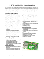
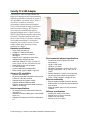
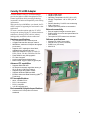
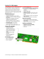
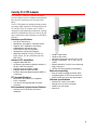
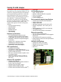
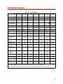
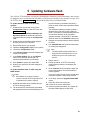
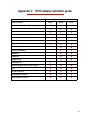
ATTO Technology, Inc.
Installation and Operation Manual
Celerity FC host adapters
Celerity FC-44ES
4-Gb FC quad channel host adapter
Celerity FC-42ES
4-Gb FC dual channel host adapter
Celerity FC-41ES
4-Gb FC single channel host adapter
Celerity FC-42XS
4-Gb FC dual channel host adapter
Celerity FC-41XS
4-Gb FC single channel host adapter
Celerity FC-21PS
2-Gb FC single channel host adapter
Celerity FC-24XL
2-Gb FC quad channel host adapter with IOPC architecture
© 2006 ATTO Technology, Inc. All rights reserved. All brand or product names are trademarks of their respective
holders. No part of this manual may be reproduced in any form or by any means without the express written
permission of ATTO Technology, Inc.
03/2006
Document Control Number: PRMA-0344-000
Contents
1 ATTO provides Fibre Channel solutions ..........................................1
Celerity FC-44ES Adapter
Hardware specifications
Advanced FC capabilities
Host bus specifications
Environmental & physical specifications
External connectivity
Software specifications
Celerity FC-42ES Adapter
Hardware specifications
Advanced FC capabilities
Host bus specifications
Environmental & physical specifications
External connectivity
Software specifications
Celerity FC-41ES Adapter
Hardware specifications
Advanced FC capabilities
Host bus specifications
Environmental & physical specifications
External connectivity
Software specifications
Celerity FC-42XS Adapter
Hardware specifications
Advanced FC capabilities
PCI bus specifications
Environmental & physical specifications
External connectivity
Software specifications
Celerity FC-41XS Adapter
Hardware specifications
Advanced FC capabilities
PCI bus specifications
Environmental & physical specifications
External connectivity
Software specifications
Celerity FC-21PS Adapter
Hardware specifications
Advanced FC capabilities
PCI bus specifications
Environmental & physical specifications
External connectivity
Software specifications
Celerity FC-24XL Adapter
Hardware specifications
IOPC specifications
Advanced FC capabilities
PCI Bus Specifications
Environmental & physical specifications
External connectivity
Software specifications
Celerity Selection Guide
ATTO Technology Inc.Celerity FC Storage Adapters Installation and Operation Manual
2 Fibre Channel is a key technology for storage ................................9
Glossary
3 Hardware installation .........................................................................11
System requirements
Fibre Channel address
Installation
Bracket details
Adapter board details
4 Configuring and updating drivers .....................................................19
Initial configuration
Windows 2000/XP/Server 2003
Mac OS X driver installation, update
Linux driver installation, update
5 Updating hardware flash ....................................................................22
6 Troubleshooting .................................................................................23
General suggestions
Mac OS X
Windows 2000/XP/Server 2003
Linux
Appendix A Standards and compliances ............................................i
FCC standards: radio and television interference
Canadian standards
European standards
Declaration of Conformity
Usage restrictions
Appendix B Accessories .......................................................................iii
Optical Cables
Fibre Channel and iSCSI solutions
SCSI solutions
Software
Appendix C SCSI adapter selection guide ..........................................iv
Appendix D Contact ATTO Technology, Inc. ......................................v
1 ATTO provides Fibre Channel solutions
The ATTO Celerity Fibre Channel family of storage products provides connectivity, intelligence and
scalability. Celerity FC host adapters simplify advanced storage networking needs such as switching,
backup and data management. Specifically designed to enhance the functionality of third party fabric
hardware and software, Celerity FC products are the industry-leading platform for storage
connectivity.
Celerity FC-44ES Adapter
The Celerity FC-44ES uses PCI Express Interconnect
and 4-Gigabit Fibre Channel to provide 4-Gb FC
speeds of up to 800 MB/sec. per channel. The FC44ES supports high-definition video, rich content
databases and other high bandwidth environments.
The FC-44ES uses PCI Express, a serial, high-speed
connection that supports aggregate throughput up to
2.2 GB/sec. (x8 PCIe). With software compatible with
existing PCI and PCI-X products, the FC-44ES uses
the same device drivers as other Celerity FC family
products, simplifying installation and support.
Hardware specifications
•
•
•
•
•
•
•
•
•
Four independent Fibre Channel ports
4-Gigabit data transfer rates per channel
800 MB/sec. maximum full-duplex throughput
per channel
Supports all FC topologies: direct fabric,
arbitrated loop and point-to-point
ANSI Fibre Channel: FC-PH, FC-FCP, FC
FCP2, FC-AL, FC-AL2, FC-PLDA, FC-FLA
Flash ROM for easy field upgrades
FC Class 3 support
Local management and diagnostics
Buffer credits: 8 @ 512 Bytes; 8 @ 2kB
•
PCI Express to PCI/PCI-X Bridge spec 1.0
Environmental & physical specifications
•
•
•
•
•
•
•
•
•
Conforms to PCI standard height, half length
form-factor specifications
Length: 6.525 inches
Height: 3.81 inches
Operating Temperature: 0-45ºC (32º-113ºF)
Storage Temperature: -40º to 70ºC (-40º to
158ºF)
Relative Humidity: 5 to 95% non-condensing
12V@ 2.1A (max.)
3.3V @ 3.0A (max.)
100 lf/m (minimum) airflow recommended
External connectivity
•
•
•
Easy-to-install full height connection plate
External LEDs for on-line and speed status for
each channel
Four pluggable optical LC SFP transceivers
included
Software specifications
•
•
•
•
Windows® XP, 2000 and Server 2003
Mac® OS X (10.4.x or later)
Red Hat Linux® (2.4 and 2.6 kernel)
SUSE Linux (2.6 kernel)
Advanced FC capabilities
•
•
•
•
•
Supports SNIA HBA API
On-demand automatic negotiation among 4-Gb,
2-Gb and 1-Gb Fibre Channel
Supports target and initiator modes
Supports Windows FDMI and WMI
Supports Exclusive Advanced Data Streaming
(ADSTM) Technology
Host bus specifications
•
•
•
x8 mechanical and x8 electrical PCI Express
Interconnect
Conforms to PCI Express Base Spec 1.0a
Conforms to PCI Express CEM Spec 1.0a
1 ATTO Technology Inc. Celerity FC Host Adapters Installation and Operation Manual
Celerity FC-42ES Adapter
The Celerity FC-42ES is a dual-channel host adapter,
providing port density for Enterprise server and
workstation applications. With 4-Gb FC speeds of up
to 800 MB/second per channel, the FC-42ES supports
the most demanding application requirements.
Additionally the FC-42ES takes advantage of the latest
in host interconnect technology, PCI Express, a serial,
high-speed connection that supports aggregate
throughput up to 2 GB/second (x8 PCIe). The FC42ES is software compatible with existing PCI and
PCI-X products using the same device drivers as other
Celerity FC family products, simplifying user
installation and support. It is backward compatible
with existing 2-Gb and 1-Gb Fibre Channel
infrastructure, protecting existing technology
investments.
•
•
100 lf/m (minimum) airflow recommended
Non RoHS
• 12V@ .035A (max.)
• 3.3V @ 1.42A (max.)
• Conforms to PCI standard height, half length
form-factor specifications
• Length: 6.525 inches
• Height: 3.81 inches
Hardware specifications
•
RoHS
• Conforms to PCI half height, half length
form-factor specifications
• 12V@ 04A (max.)
• 3.3V @ 1.5A (max.)
• Length: 5.6 inches
• Height: 2.712 inches
•
•
•
•
•
•
•
•
•
2 independent Fibre Channel ports
4-Gigabit data transfer rates per channel
800 MB/sec. maximum full-duplex throughput
per channel
Supports all FC topologies: direct fabric,
arbitrated loop and point-to-point
ANSI Fibre Channel: FC-PH, FC-FCP, FC,
FCP2, FC-AL, FC-AL2, FC-PLDA, FC-FLA
Flash ROM for easy field upgrades
FC Class 3 support
Local management and diagnostics
Buffer credits: 8 @ 512 Bytes; 8 @ 2kB
Advanced FC capabilities
•
•
•
•
•
Supports SNIA HBA API
On-demand automatic negotiation among 4-Gb,
2-Gb and 1-Gb Fibre Channel
Supports target and initiator modes
Supports Windows® FDMI and WMI
Supports Exclusive Advanced Data Streaming
(ADSTM) Technology
Host bus specifications
•
•
•
•
x8 mechanical and x8 electrical PCI Express
Interconnect (non RoHS); x4 mechanical and x4
electrical PCI Express interconnect
Conforms to PCI Express Base Spec 1.0a
Conforms to PCI Express CEM Spec 1.0a
PCI Express to PCI/PCI-X Bridge spec 1.0
Environmental & physical specifications
•
•
•
Operating Temperature: 0-45ºC (32º-113ºF)
Storage Temperature: -40º to 70ºC (-40º to
158ºF)
Relative Humidity: 5 to 95% non-condensing
External connectivity
•
•
•
Easy-to-install full height connection plate
External LEDs for on-line and speed status for
each channel
Two pluggable optical LC SFP transceivers
included
Software specifications
•
•
•
•
Windows XP, 2000 and Server 2003
Mac OS X (10.4.x or later)
Red Hat Linux (2.4 and 2.6 kernel)
SUSE Linux (2.6 kernel)
2
Celerity FC-41ES Adapter
The Celerity FC-41ES is a single-channel host
adapter providing support for the most demanding
application requirements. With 4-Gb FC speeds of
up to 800 MB/sec. per channel, the FC-41ES is a
cost effective connectivity solution for
environments requiring maximum throughput.
The FC-41ES also takes advantage of the latest in
host interconnect technology: PCI Express, a
serial, high-speed connection that supports
aggregate throughput up to 1 GB/sec. (x4 PCIe).
The FC-41ES is software compatible with existing
PCI and PCI-X products using the same device
drivers as other Celerity FC products, simplifying
user installation and support. It is backward
compatible with existing 2-Gb and 1-Gb Fibre
Channel infrastructure, protecting existing
technology investments.
Hardware specifications
•
•
•
•
•
•
•
•
•
Single Fibre Channel port
4-Gigabit FC data transfer rates
800 MB/sec. maximum full-duplex
throughput
Supports all FC topologies: direct fabric,
arbitrated loop and point-to-point
ANSI Fibre Channel: FC-PH, FC-FCP, FC
FCP2, FC-AL, FC-AL2, FC-PLDA, FC-FLA
Flash ROM for easy field upgrades
FC Class 3 support
Local management and diagnostics
Buffer credits: 8 @ 512 Bytes; 8 @ 2 KB
Advanced FC capabilities
•
•
•
•
•
Supports SNIA HBA API
On-demand automatic negotiation among 4-Gb,
2-Gb and 1-Gb Fibre Channel
Supports target and initiator modes
Supports Windows FDMI and WMI
Features exclusive Advanced Data Streaming
(ADSTM) Technology
Host bus specifications
•
•
•
x4 mechanical and x4 electrical PCI Express
interconnect
Supports PCI Express Base Spec 1.0a and CEM
Spec 1.0a
Supports PCI Express to PCI/PCI-X bridge spec
1.0
Environmental & physical specifications
•
•
•
•
•
•
•
•
Conforms to PCIe low profile form factor
specifications
Length: 5.600 inches
Height: 2.712 inches
Operating Temperature: 0-45ºC (32º-113ºF)
Storage Temperature: -40º to 70ºC (-40º to
158ºF)
Relative Humidity: 5 to 95% non-condensing
100 lf/m (minimum) airflow recommended
Power: 12V@ 0.4A max; [email protected] max.
External connectivity
•
•
•
Easy-to-install full height connection bracket
External LEDs for on-line and speed status for
each channel
Single pluggable optical LC SFP transceiver
included
Software specifications
•
•
•
•
Windows XP, 2000, Server 2003
Red Hat Linux (2.4 and 2.6 kernel)
SUSE Linux (2.6 kernel)
Mac OS X (10.4.x or later)
3 ATTO Technology Inc. Celerity FC Host Adapters Installation and Operation Manual
Celerity FC-42XS Adapter
The dual-channel Celerity FC-42XS host adapter
provides the highest available throughput for Fibre
Channel applications while protecting technology
investments via backward compatibility with existing
infrastructure.
With speeds of up to 800 MB/sec. per channel, the FC42XS is capable of supporting the most intensive data
applications.
To ensure a smooth transition path, the FC-42XS
leverages the existing Celerity FC software hardware
architecture, allowing ATTO to deliver industryleading quality and stable software architecture.
•
•
•
•
•
•
•
Length: 6.600 inches
Height: 2.536 inches
Operating Temperature: 0-45ºC (32º-113ºF)
Storage Temperature: -40º to 70ºC (-40º to
158ºF)
Relative Humidity: 5 to 95% non-condensing
5V@ 1.5A (max.)
100 lf/m (minimum) airflow recommended
External connectivity
•
•
•
Easy-to-install full height connection plate
External LEDs for on-line and speed status for
each channel
Two optical LC SFP transceivers included
Hardware specifications
Software specifications
•
•
•
•
•
•
•
•
•
•
•
•
•
Two independent Fibre Channel ports
4-Gigabit data transfer rates per channel
800 MB/sec. maximum full-duplex throughput
per channel
Supports all FC topologies: direct fabric,
arbitrated loop and point-to-point
ANSI Fibre Channel: FC-PH, FC-FCP, FC
FCP2, FC-AL, FC-AL2, FC-PLDA, FC-FLA
Flash ROM for easy field upgrades
FC Class 3 support
Local management and diagnostics
Buffer credits: 8 @ 512 bytes; 8 @ 2k bytes
Windows XP, 2000, Server 2003
Red Hat Linux (2.4 and 2.6 kernel)
SUSE Linux (2.6 kernel)
Mac OS X
Advanced FC capabilities
•
•
•
•
•
Supports SNIA HBA API
On-demand automatic negotiation among 4Gb, 2-Gb and 1-Gb Fibre Channel
Supports target and initiator modes
Supports Windows FDMI and WMI
Exclusive Advanced Data Streaming (ADSTM)
Technology
PCI bus specifications
•
•
•
•
64-bit, 133 MHz PCI-X
PCI-X 1.0a compliant
PCI 2.2 compliant
3.3V PCI signaling only
Environmental & physical specifications
•
Conforms to PCI low profile form factor
standards
4
Celerity FC-41XS Adapter
The single-channel Celerity FC-41XS provides speeds
of up to 800 MB/sec. using full 4-Gigabit Fibre
Channel performance while being fully backwardcompatible with existing 2-GB and 1-Gb Fibre
Channel infrastructure, protecting existing technology
investments. It is capable of supporting the most dataintense applications.
Hardware specifications
•
•
•
•
•
•
•
•
•
One Fibre Channel port
4-Gigabit data transfer rates per channel
800 MB/sec. maximum full-duplex throughput
per channel
Supports all FC topologies: direct fabric,
arbitrated loop and point-to-point
ANSI Fibre Channel: FC-PH, FC-FCP, FC
FCP2, FC-AL, FC-AL2, FC-PLDA, FC-FLA
Flash ROM for easy field upgrades
FC Class 3 support
Local management and diagnostics
Buffer credits: 8 @ 512 bytes; 8 @ 2k bytes
Advanced FC capabilities
•
•
•
•
•
Supports SNIA HBA API
On-demand automatic
negotiation among 4-Gb, 2Gb and 1-Gb Fibre Channel
Supports target and initiator
modes
Supports Windows FDMI
and WMI
Exclusive Advanced Data
Streaming (ADSTM)
Technology
•
3.3V PCI signaling only
Environmental & physical specifications
•
•
•
•
•
•
•
•
Conforms to PCI low profile form factor
standards
Length: 6.600 inches
Height: 2.536 inches
Operating Temperature: 0-45ºC (32º-113ºF)
Storage Temperature: -40º to 70ºC (-40º to
158ºF)
Relative Humidity: 5 to 95% non-condensing
5V@ 1.5A (max.)
100 lf/m (minimum) airflow recommended
External connectivity
•
•
•
Easy-to-install full height connection plate
External LEDs for on-line and speed status for
each channel
Optical LC SFP transceiver included
Software specifications
•
•
•
•
Windows XP, 2000, Server 2003
Red Hat Linux (2.4 and 2.6 kernel)
SUSE Linux (2.6 kernel)
Mac OS X
PCI bus specifications
•
•
•
64-bit, 133 MHz PCI-X
PCI-X 1.0a compliant
PCI 2.2 compliant
5 ATTO Technology Inc. Celerity FC Host Adapters Installation and Operation Manual
Celerity FC-21PS Adapter
The Celerity FC-21PS Fibre Channel host adapter
provides a single 2-Gb Fibre Channel connection from
host devices to the Storage Area Network (SAN)
fabric.
The FC-21PS supports the leading operating systems,
providing a single solution for all connectivity needs.
As with all Celerity FC products, the FC-21PS is
designed for high-quality data transmission, ensuring
that critical information is delivered correctly the first
time to reduce fabric traffic and improve overall fabric
efficiency.
Hardware specifications
•
•
•
•
•
•
One Fibre Channel port
400 MB/sec. throughput in full duplex mode
Supports all FC topologies: direct fabric,
arbitrated loop and point-to-point
Flash ROM for easy field upgrades
Simultaneous multi-protocol support
ANSI Fibre Channel: FC-PH, FC-FCP, FCFCP2, FC-AL, FC-AL2, FC-PLDA, FC-FLA,
IETF-IPFC
Advanced FC capabilities
•
•
•
•
•
Supports SNIA HBA API
On-demand, automatic negotiation between 2Gb and 1-Gb Fibre Channel
Supports target and initiator modes
Supports Windows FDMI and WMI
Exclusive Advanced Data Streaming (ADSTM)
Technology
PCI bus specifications
•
•
•
64-bit/32-bit, 66/33 MHz PCI compatible
PCI 2.3 compliant
3.3V and 5V PCI signaling with universal
connector
Environmental & physical specifications
•
Conforms to PCI low profile form factor
standards
•
•
•
•
•
•
•
Length: 6.600 inches
Height: 2.536 inches
Operating Temperature: 0-45ºC (32º-113ºF)
Storage Temperature: -40º to 70ºC (-40º to
158ºF)
Relative Humidity: 5 to 95% non-condensing
5V@ 1.5A (max.)
100 lf/m (minimum) airflow recommended
External connectivity
•
•
•
Easy-to-install full height connection plate
Integrated optical LC SFF fixed transceiver
External LEDs for on-line and speed status
Software specifications
•
•
•
•
Windows XP, 2000, Server 2003
Red Hat Linux (2.4 and 2.6 kernel)
SUSE Linux (2.6 kernel)
Mac OS X
6
Celerity FC-24XL Adapter
The Celerity FC-24XL is a Fibre Channel advanced
host adapter with four independent channels of 2-Gb
connectivity and advanced functions and embedded
processing and buffering capabilities to enable data
stream manipulation, direct port-to-port transfers,
offload processing, video handling and a myriad of
other capabilities. The Integrated Offload &
Processing Center (IOPC) uses an Intel XScale®
processor core and an internal 133 MHz PCI-X data
bus for top performance and low latency. IOPC
simplifies and augments SAN fabric management,
including:
•
•
•
•
•
•
Port-to-port data streaming
Hardware RAID
Backup offload
Metadata insertion
Data protection
Video handling
Hardware specifications
•
•
•
•
•
•
Four independent data channels, each
supporting 2-Gb Fibre Channel performance
2.125-Gigabit data transfer rates per channel
400 MB/sec. maximum full duplex throughput
per channel
Supports all FC topologies: direct fabric,
arbitrated loop and point-to-point
Flash ROM for easy field upgrades
Simultaneous multi-protocol support
IOPC specifications
•
•
•
•
•
•
Technology
PCI Bus Specifications
•
•
•
•
•
64-bit, 133 MHz PCI-X
64/32-bit, 100/66/33 MHz PCI compatible
PCI-X 1.0a compliant
PCI 2.3 compliant
3.3V PCI signaling only
Environmental & physical specifications
•
•
•
•
•
•
•
•
Conforms to PCI full form factor standards
Length: 6.600 inches
Height: 4.200 inches
Operating Temperature: 0-45ºC (32º-113ºF)
Storage Temperature: -40º to 70ºC (-40º to
158ºF)
Relative Humidity: 5 to 95% non-condensing
+3.3 [email protected] (max.)
100 lf/m (minimum) airflow recommended
External connectivity
•
•
•
•
Easy-to-install connection plate
Up to four shortwave optical LC SFP pluggable
transceivers
Two optical LC SFP transceivers included
External LEDs to show on-line and speed status
for each channel
Software specifications
•
•
•
•
Windows XP, 2000, Server 2003
Red Hat Linux (2.4 and 2.6 kernel)
SUSE Linux (2.6 kernel)
Mac OS X
Developer’s kit for OEMs
Intel IOP80331 XScale processor core
Supports up to 512 MB DDR 333 MHz SDRAM
Internal 133 MHz PCI-X bus
EDC error correction hardware capable of endto-end data integrity
ANSI Fibre Channel: FC-PH, FC-FCP, FCFCP2, FC-AL, FC-AL2, FC-PLDA, FC-FLA,
IETF-IPFC
Advanced FC capabilities
•
•
•
•
•
Supports SNIA HBA API
On-demand, automatic negotiation between 2Gb and 1-Gb Fibre Channel
Supports target and Initiator modes
Supports Windows FDMI and WMI
Exclusive Advanced Data Streaming (ADSTM)
7 ATTO Technology Inc. Celerity FC Host Adapters Installation and Operation Manual
Celerity Selection Guide
Celerity FC host adapters
Product
FC-44ES
Features .............
FC-42ES
FC-41ES
FC-42XS
FC-41XS
FC-24XL
FC-21PS
4
2
1
2
1
4
1
4-Gb
4-Gb
4 GB
4-Gb
4-Gb
2-Gb
2-Gb
Maximum Transfer
Rate (half duplex)
1.6 GB/sec
800 MB/sec
400 MB/sec
800 MB/sec
400 MB/sec
800 MB/sec
200 MB/sec
Maximum Transfer
Rate (full duplex)
2 GB/sec
1 GB/sec
800 MB/sec
1 GB/sec1
800 MB/sec
1 GB/sec1
400 MB/sec
Fibre Channel ports
FC protocol
Bus type
PCIe
PCIe
PCIe
PCI-X
PCI-X
PCI-X
PCI
Bus characteristics2
8 lane
4 lane
4 lane
64-bit
133 MHz2
64-bit
133 MHz2
64-bit
133 MHz2
64-bit
66 MHz2
Optical interface
SFP LC
SFP LC
SFP LC
SFP LC
SFP LC
SFP LC
SFF LC
Maximum cable
length
300m@2-Gb
150m@4-Gb
300m@2-Gb
150m@4-Gb
300m@2-Gb
150m@4-Gb
300m@2-Gb
150m@4-Gb
300m@2-Gb
150m@4-Gb
500m@1-Gb
300m@2-Gb
500m@1-Gb
300m@2-Gb
9
9
9
9
Low profile form
factor
Advanced Data
Streaming (ADS)
Technology
9
9
9
9
9
9
9
Software RAID
support3
9
9
9
9
9
9
9
Developer's Kit
(Target Mode & API)
9
9
9
9
9
9
9
Developer's Kit
(Advanced)
9
Integrated Offload &
Processing Center
(IOPC)
9
Onboard memory for
Direct Memory
Transfers
9
Windows support
9
9
9
9
9
9
9
Linux (Red Hat,
SUSE) driver support
9
9
9
9
9
9
9
Macintosh OS X
(Tiger) driver support
9
9
9
9
9
9
9
RoHS compliant
version
9
9
9
9
9
1 Performance ceiling is constrained by 133 MHz PCI-X bus transfer speed
2 Backward compatible to 32-bit and 33 MHz PCI; FC-24XL is 3.3V; FC-21PS is 3.3V/5V Universal
3 ATTO ExpressStripe for OS X available; Express Power Center and other software RAID supported for Windows
8
2 Fibre Channel is a key technology for storage
Fibre Channel is a serial communications technology designed to transfer large amounts of data among
a variety of hardware systems over long distances. It is a key technology for applications that require
shared, high bandwidth access to storage.
Fibre Channel provides a logical, point-to-point,
serial channel for the transfer of data between a
buffer at a source device and a buffer at a
destination device. It moves buffer contents from
one port to another, without regard to the format
or meaning of the data so different upper level
protocols are able to run over Fibre Channel
hardware.
The Fibre Channel architecture is structured as a
hierarchical set of protocol layers. Defined within
these layers are rules for signal interfaces, serial
encoding and decoding, error control, frame
format and communications protocols.
Glossary
Some terms used in the Fibre Channel industry are defined below. More information is available through
the ATTO Technology web site (www.attotech.com), the Fibre Channel Industry Association
(www.fibrechannel.com), Cern (www.cern.ch), the Storage Area Networking Industry Association
(www.snia.org), and the Fibre Channel Consortium (www.iol.unh.edu/consortiums, click on FC).
Term
Definition
ANSI
American National Standards Institute
arbitrate
process of selecting one L_Port from a collection of ports which ask for use of the arbitrated loop
at the same time
arbitrated loop
a loop topology (FC-AL) in which two or more ports are interconnected, but only two ports can
communicate at one time; low-cost solution which may or may not use hubs and switches
auto negotiation
hardware senses and automatically responds depending on configuration
BER
Bit Error Rate: a measure of transmission accuracy; the ratio of bits received in error to bits sent
bit
smallest unit of data a computer can process: a single binary digit with a value of either 0 or 1
bus
a collection of unbroken signal lines used to transmit information from one part of a computer
system to another; taps on the lines connect devices to the bus
byte
an ordered set of 8 bits
channel
a point-to-point link which transports data from one point to another
CPU
Central Processing Unit: the portion of the computer that actually performs computations
CRC
Cyclic Redundancy Check: an error-correcting code which calculates a numeric value for received
and transmitted data; if no error has occurred during transmission, the CRC for both received and
transmitted data should be the same
destination
address
a value in the frame header of each frame which identifies the port in the node where the frame is
being sent
device driver
a program that allows a microprocessor to direct the operation of a peripheral device
DMA
Direct Memory Access: a way to move data from a storage device directly to RAM without using
the CPU’s resources
DMA bus master
allows a peripheral to control the flow of data to and from system memory by block as opposed to
allowing the processor to control the data by bytes (PIO or programmed I/O)
9 ATTO Technology Inc. Celerity FC Host Adapters Installation and Operation Manual
Term
Definition
fabric
a Fibre Channel switch or two or more Fibre Channel switches interconnected to physically
transmit data between any two N_Ports on the switch or switches
FC
Fibre Channel
F_port
a port in the Fibre Channel fabric where a N_port may attach
FL_port
a port in the Fibre Channel fabric where a NL_port may attach in an arbitrated loop
frame
an indivisible unit for transfer of information in Fibre Channel
frame header
the first field in the frame containing the address and other control information about the frame
full duplex
a communication protocol which allows transmission in both directions at the same time
half duplex
a communication protocol which allows transmission in both directions, but only one direction at a
time
host
a processor, usually a CPU and memory, which communicates with devices over an interface
initiator device
a component which originates a command
L_port
a port in an arbitrated loop, either a NL_port or a FL_port
LED
Light-emitting diode: a type of diode that emits light when current passes through it; visible LEDs
are used as indicator lights on all sorts of electronic devices
LUN
Logical Unit Number: an identifier for a logical unit (0-7)
multi-mode fiber
an optical fiber which can carry several beams of light at once
N_port
a port attached to a node used with point to point or fabric configurations
NL_ port
a port attached to a node in Fibre Channel arbitrated loop or fabric loop configuration
originator
an initiating device; a component which originates a command
parity checking
a method which verifies the accuracy of data transmitted over the SCSI bus by adding one bit in
the transfer to make the sum of all the bits either odd or even (for odd or even parity); an error
message occurs if the sum is not correct
PCI
Peripheral Component Interconnect. Allows peripherals to be connected directly to computer
memory, bypassing the slower ISA and EISA busses
point-to-point
a topology where two ports communicate
port
an access point in a device: see N_port, NL_port, etc.
port address
also port number; the address, assigned by the PCI bus, through which commands are sent to a
host adapter board
port number
see port address
receiver
the ultimate destination of data transmission; a terminal device
scatter/gather
a device driver feature which allows the host adapter to modify a transfer data pointer so that a
single host adapter can access many segments of memory, minimizing interrupts and transfer
overhead
SCSI
Small Computer Systems Interface: a processor-independent standard for system-level interface
between a computer and intelligent devices including hard disks, floppy disks, CD-ROM, printers,
scanners, etc.
single-mode fiber an optical fiber with a small core which supports one wavelength (ray of light); the core radius is
nearly equal to the wavelength of the source
topology
logical layout of the parts of a computer system or network and their interconnections
transceiver
a transmitter/receiver module
transfer rate
the rate at which bytes or bits are transferred, as in megabytes or gigabits per second
10
3 Hardware installation
You need a basic understanding of Fibre Channel before installing the Celerity FC host adapter. Please
refer to Fibre Channel is a key technology for storage on page 9 for a list of related web sites.
WWN 0
WWN 1:
WWN 2
WWN 3
CAUTION
Back up your system data before
changing or installing any hardware.
System requirements
The Celerity FC host adapter package contains the
host adapter, the ATTO Utilities CD and a
warranty and registration card. If any of these
items are missing, contact your ATTO authorized
sales representative.
To install and use the Celerity Fibre Channel host
adapter you need
all adapters
44ES, 42ES, 42XS, 24XL
44ES, 24XL
44ES, 24XL
Installation
CAUTION
Celerity FC host adapters contain
components that are sensitive to
electrostatic discharge (ESD). ESD can
cause damage to the Celerity FC host
adapter. Please follow standard methods
to avoid ESD.
•
A computer with an available PCI, PCI-X or PCI
Express expansion slot.
1
Power down the computer and unplug the
computer from all power sources.
•
The complete Celerity FC host adapter package.
2
Open the case.
3
Install the Celerity FC host adapter in any open
Fibre Channel address
Celerity FC adapters are configured with a unique
address designated by the Institute of Electrical
and Electronic Engineers. The WorldWide Port
Name (WWN) and Node Name are the two
components of the address assigned to Fibre
Channel products. This address, stored in flash
memory, allows the system to recognize the
Celerity host adapter as a unique part of your
configuration. The address is clearly marked on
the back of the board for easy identification.
Please keep a reference copy of the number in a
safe place or write in the space provided on this
page.
Celerity FC host adapter WWNs are assigned for
each channel. The WWN listed on your host
adapter is assigned to the first channel (0).
Sequential WWNs apply for additional channels.
PCI, PCI-X or PCI Express expansion slot. If
you have questions about how to install an
expansion card in your system, consult your
computer’s documentation.
Note
The Celerity FC-24XL, FC-41XS, and FC42XS host adapters only fit in 3.3V slots.
The Celerity FC-44ES and FC-42ES (non
RoHS) fit in 8x or 16x mechanical PCI
Express slots.
The Celerity FC-42ES (RoHS) and FC-41ES
fit into 4x, 8x, or 16x mechanical PCI
Express slots.
If you have trouble seating your adapter in a
32-bit PCI bus computer, check to make sure
the connector can accommodate 64-bit host
adapters.
4
Connect Fibre Channel devices by inserting a
Fibre Channel cable from the devices to the
connectors on the Celerity FC host adapter until
you hear a click.
5
Close the case on the computer and power it
up.
11 ATTO Technology Inc. Celerity FC Host Adapters Installation and Operation Manual
Bracket details
Exhibit 3-1
FC-44ES Adapter
Exhibit 3-3
FC-41ES Adapter
Link LEDS
If Link LED is lit, the storage
adapter is online
Speed LEDs
indicate 4Gb
SFP LC optical
connectors
Speed LED
indicate 4Gb
Link LED
If Link LED is lit, the storage
adapter is online
SFP LC optical
connector
Exhibit 3-4
Exhibit 3-2
Speed LEDs
indicate 4Gb
FC-42XS Adapter
FC-42ES Adapter
Link LEDS
If Link LED is lit, the
storage adapter is online
SFP LC optical
connectors
12
Exhibit 3-5
FC-41XS Adapter
Exhibit 3-7
FC-24XL Advanced Adapter
If LED lit, indicates
the channel is using
2-Gb FC
If LED lit, the storage
adapter is online
If LED lit, adapter is online
SFP LC optical
connectors
SFP LC optical
connector
FC24XL
Exhibit 3-6
FC-21PS Adapter
If LED lit, indicates the
channel is using 2-Gb FC
If LED lit, the storage
adapter is online
SFF duplex LC
optical connector
13 ATTO Technology Inc. Celerity FC Host Adapters Installation and Operation Manual
Adapter board details
Exhibit 3-8
FC-44ES
FC controller
SFP LC
optical
connectors
PCI Express connector
Exhibit 3-9
FC-42ES Non-RoHS
FC
c o n tro lle r
S F P L C o p tic a l
c o n n e c to rs
P C I E x p re s s c o n n e c to r
14
Exhibit 3-10
FC-42ES RoHS
F C co n tro lle r
S F P L C o p tica l
co n n e cto rs
P C I E xp re ss co n n e cto r
Exhibit 3-11
FC-41ES
FC controller
SFP LC optical
connector
PCI Express connector
15 ATTO Technology Inc. Celerity FC Host Adapters Installation and Operation Manual
Exhibit 3-12
FC-42XS
F C c o n tro lle r
SFP LC
o p tic a l
c o n n e c tors
P C I-X c o n n e c to r
Exhibit 3-13
FC-41XS
FC controller
SFP LC
optical
connector
PCI-X connector
Exhibit 3-14
FC-21PS
SFF duplex LC optical connector
FC controller
PCI connector
16
Exhibit 3-15
FC-24XL
Intel 80331 XScale
pluggable SFP LC optical
connectors
FC controllers
PCI-X connector
17 ATTO Technology Inc. Celerity FC Host Adapters Installation and Operation Manual
18
4 Configuring and updating drivers
Celerity FC host adapters require a current device driver and hardware flash for proper operation.
Your adapter was properly flashed before shipment, but the flash memory may need to be updated as
new versions become available or if the factory-installed version becomes corrupt. This chapter deals
with installing and updating device drivers. Refer to Updating hardware flash on page 22 for
information on updating hardware flash. Visit the ATTO web site, www.attotech.com, to download the
latest drivers and flash bundle.
Initial configuration
While the factory settings on your Celerity FC
host adapter should provide excellent
performance for a wide range of applications,
some specialized applications may benefit from
modification of adapter settings. The ATTO
Utilities Installation and Operation Manual
provides detailed information on using ATTO
Technology configuration utilities found on the
ATTO Utilities CD or downloaded from the
ATTO website.
For best performance, use the most recent device
driver and flash version.
To verify the version:
Windows: Use the ATTO Configuration Tool
from the ATTO Utilities CD, or downloaded from
www.attotech.com, or use a combination of the
adapter boot string during system boot and the
Device Manager.
Note
Windows NT is only supported with Celerity
driver version 1.31 or earlier. If you are using
Windows NT, contact your service
representative.
Mac OS X: Use the ATTO Configuration Tool on
the ATTO Utilities CD, or downloaded from
www.attotech.com, or use the Apple System
Profiler.
Linux: Use the ATTO Configuration Tool on the
ATTO Utilities CD, or downloaded from
www.attotech.com, or to find the driver version,
examine /proc/scsi/celerityfc/X, where X is the
adapter’s host number.
Windows 2000/XP/Server 2003
Five procedures are described below. Review
each thoroughly to ensure that you are using the
one that best fits your needs.
If you have one or more Celerity FC adapters
installed in your system and you are installing
additional adapter(s), you do NOT need to
perform any of these procedures unless you are
updating a previously installed driver. The
Celerity FC Installation Disk can be the
Installation CD shipped with your adapter, a
folder containing the latest downloaded and
expanded driver, or a Celerity FC installation
floppy disk.
The Installation CD automatically starts when
inserted in the system CD-ROM drive. Navigate
the easy-to-use HTML-based menu to find the
driver that you want to install. If the CD does not
automatically start, use Explorer and run
autorun.bat.
Upgrading your existing Celerity FC driver
1
Log on to Windows as the System
Administrator.
2
Insert your Celerity FC Installation Disk and run
autorun.bat
3
In Windows Drivers, select your operating
system and Install Driver.
19 ATTO Technology Inc. Celerity FC Host Adapters Installation and Operation Manual
Adding a Celerity FC adapter to an existing
Windows installation
Note
Complete this installation procedure before
attaching any devices to the adapter.
1
Complete the steps in Upgrading your existing
Celerity FC driver on page 19 to pre-install the
driver.
2
Shutdown Windows when Setup prompts you
to do so.
3
Install your new Celerity FC adapter into an
available PCI expansion slot.
4
Restart Windows. During the boot process,
Windows detects your Celerity FC adapter and
the Found New Hardware Wizard is
displayed.
5
Use the default settings for each adapter
channel.
6
Insert the Celerity FC Installation disk when
asked to do so.
7
When adapter installation is complete, the
Found New Hardware Wizard displays an
ATTO Phantom Device for each channel. Use
the wizard default settings to complete the
installation.
8
Shut down the system and set up the final
adapter configuration.
a. If the Celerity FC adapter is replacing
another adapter in the system,
disconnect the FC cables from the
adapter and remove the adapter from
the system, or you can move the
Celerity FC adapter to the PCI slot that
the previous adapter occupied if this
slot is more suitable for the Celerity FC
adapter.
b. Attach the appropriate FC cables to the
Celerity FC adapter.
c. Close the computer chassis, turn on
the power and restart Windows.
Note
If you moved the adapter to a different PCI
slot, the Found New Hardware Wizard
displays. Proceed through the wizard with
the default settings for each adapter channel
to complete the installation.
Install a fresh copy of the Windows OS onto a
disk attached to the Celerity FC adapter
Note
The Celerity FC driver does not support boot
functionality on Itanium systems; therefore,
the procedure described below does not
apply to Windows Server 2003 for Itanium
systems.
1
Start Windows text mode setup as per the
instructions provided with Windows.
2
Press F6 when the first blue window, called
Windows Setup, displays.
The setup program displays a prompt in the
status window on the bottom left of the monitor.
Setup continues to load files after you press F6.
3
A new window displays instructions to specify
additional mass storage devices. Press S
indicating that you wish to install a storage
device.
4
Insert the Celerity FC installation diskette in
drive A: and press Enter.
5
A screen displays a list of Celerity FC adapters.
Select your adapter and press Enter.
6
Windows Setup loads the files from the floppy
and then displays the screen described in step
2. The ATTO Celerity FC device should now
be listed as detected.
7
Repeat steps 2 - 4 for any other vendorsupplied driver installation disks.
8
After all other drivers have been processed,
press Enter and proceed with the rest of the
Windows Installation procedure.
Note
When Windows begins copying files to your
hard disk, a display prompts you to insert the
Celerity FC installation disk and any other
vendor-supplied disks you used during
custom installation. This is normal. The first
time you inserted the disks, Windows only
loaded the drivers into memory; the second
time you insert the disk(s), Windows is
copying the driver to your hard disk.
20
Create a Celerity FC installation floppy disk
from the Celerity FC Installation CD
1
Create a floppy disk from a Celerity FC driver
download from the ATTO Technology website
Note
You must have a floppy disk with the Celerity
FC driver software to install a fresh copy of
the Windows OS onto a disk attached to a
Celerity FC adapter.
1
Download the latest driver software from the
ATTO web site, www.attotech.com.
2
Insert the Installation CD into a CD-ROM. The
installation starts automatically start.
The download is a self-extracting executable
that expands the driver software package. Run
the self-extracting executable and select a
folder to place the expanded software package.
3
Navigate to the folder with the desired Celerity
FC driver.
If the Celerity FC installation does not start,
navigate to the root of the CD and run
autorun.bat
2
Select Windows Drivers from the items on the
left side of the screen.
3
Select the appropriate CPU-based operating
system from operating system choices.
4
Select Create Miniport Driver Diskette or
Create StorPort Driver Diskette for the
desired operating system.
5
Note
The expanded software package contains a
Miniport driver and may contain a StorPort
driver. The Celerity FC Windows Miniport
driver is in the base directory of the
expanded software package. The Celerity
FC Windows StorPort driver is in the
StorPort subdirectory.
4
Follow the instructions for creating the floppy
disk.
Run makedisk.bat and follow the instructions
for creating the floppy disk.
Mac OS X driver installation, update
New or previous installation
1
Extract the latest version of the device driver file
to your desktop.
2
Double click the installer icon and follow the on
screen prompts.
3
Reboot your system for the changes to take
effect.
2
Download the appropriate version of the device
driver from the ATTO web site.
3
At the command prompt, extract the file using
the command tar -xfz <filename.tgz>
4
Enter the directory created in the above step
and type make install to overwrite any
previously-installed driver.
5
Start the driver by typing modprobe celerityfc
Linux driver installation, update
New or previous installation
Note
You must have kernel header files for the
appropriate kernel installed.
You must be logged in as root.
1
If updating an existing Celerity FC driver, at the
command prompt type rmmod celerityfc
21 ATTO Technology Inc. Celerity FC Host Adapters Installation and Operation Manual
5 Updating hardware flash
Your Celerity FC host adapter was properly flashed before shipment, but the flash memory may need to
be updated as new versions become available or if the factory-installed version becomes corrupt. Visit
the ATTO website, www.attotech.com, to download the latest drivers and flash bundle.
the self-extracting executable and select a
folder in which to place the expanded software
package.
To update hardware flash in all operating
systems
1
Download the most recent version of the
Configuration Tool from the ATTO web site,
www.attotech.com.
The expanded software package contains a
Miniport driver and may contain a StorPort
driver. The Celerity FC Windows Miniport driver
is in the base directory of the expanded
software package. The Celerity FC Windows
StorPort driver is in the StorPort subdirectory.
Refer to the ATTO Utilities Installation and
Operation Manual for additional information
on downloading and using the Configuration
Tool.
2
Download the proper flash bundle (adapter
specific) from the ATTO web site.
3
Navigate to the folder with the desired Celerity
FC driver.
3
Extract these files to your desktop.
4
Run makedisk.bat and follow the instructions
for creating the floppy disk.
4
Install the Configuration Tool on your system.
5
Launch the Configuration Tool.
6
In the Device window, select the adapter that
needs to be updated.
7
In the Flash window, click on the Browse
button to find the flash bundle that you
previously downloaded to your desktop.
5
Reboot the PC.
8
Click Update to update your flash ROM.
6
9
Reboot your system for the flash changes to
take effect.
During the reboot, an ATTO Technology
banner displays that the host adapter was
detected.
7
Enter Control-F when prompted to begin the
set-up utility within a few seconds after the
banner appears.
To update hardware flash on a PC using the
BIOS utilities
Note
BIOS utilities do not work on Itanium
systems. Use the ATTO Configuration Tool
to update flash on Itanium systems.
1
Download the latest driver software from the
ATTO Technology website.
2
The download is a self-extracting executable
that expands the driver software package. Run
Note
The flash update must be loaded from a
floppy because CD-ROM drivers are not
loaded at this point in the system boot
process.
If you do not enter Control-F soon enough after
the banner appears, repeat steps 5 and 6.
8
In the utility, select the Upgrade Flash ROM
option.
9
Insert the disk into the drive slot.
10 Follow the on-screen instructions.
11 Remove the disk and reboot your system for
the flash ROM changes to take effect
22
6 Troubleshooting
This chapter contains solutions for the most common problems you might encounter. If you need
additional assistance, please refer to the ATTO Technology web site (www.attotech.com) or contact an
ATTO Technology authorized representative.
General suggestions
•
Check each cable connection on every device.
•
Verify all cables are in proper working condition.
Loose or broken cables are often the cause of
errors or problems.
•
Check that Fibre Channel devices are plugged
into an AC outlet and are turned on before you
add power to your computer.
Mac OS X
Note
The Celerity FC supports Mac OS X versions
10.3 and later.
3
a. Click on the adapter name in the
Device Listing to view the Basic Info
screen.
If devices are not accessible
1
2
b. If the Driver Information section
indicates Unknown: driver not
loaded, reinstall the driver. Refer to
Configuring and updating drivers on
page 19.
Open the ATTO Configuration Tool from the
ATTO Utilities CD or download from the ATTO
website. Refer to the ATTO Utilities Installation
and Operation Manual for additional
information.
If the adapter does not appear in the Device
Listing, make sure it is properly seated in the
PCI slot.
Verify the driver is loaded.
c. If reinstalling the driver does not fix the
problem, contact an ATTO authorized
representative.
4
a. Remove power from the PC.
b. Remove the case.
c. Check the PCI slot.
Reset the NVRAM for all channels to defaults
and reboot. If the problem persists, contact an
ATTO authorized representative.
Note
When calling ATTO Technical Support,
please have a printout of the IOreg listing
and output from the Apple System Profiler
available.
d. Replace the case.
e. Apply power.
Note
If it is properly seated and devices are still
not accessible, contact an ATTO Technology
authorized representative.
Windows 2000/XP/Server 2003
•
If the card has been recently re-flashed, the new
Windows driver must be installed. Follow the
procedure in Configuring and updating drivers
on page 19.
•
All of the external devices connected to the host
adapter should be identified. If they do not
appear in the Device Manager, the external
devices or connection may not be working
properly.
•
For Intel-based PCs, check the computer CMOS
setup and verify that the PCI slots are configured
correctly.
•
Procedures vary greatly: refer to the manual
supplied with your system or call the computer
supplier for configuration assistance.
•
Windows 2000/XP/Server 2003 are Plug-n-Play
operating systems: be sure your computer’s
BIOS is set accordingly.
23 ATTO Technology Inc. Celerity FC Host Adapters Installation and Operation Manual
•
a. Remove power from the PC.
If these do not solve the problem, re-flash the
host adapter and re-install the Windows
2000/XP/Server 2003 driver. See Configuring
and updating drivers on page 19.
If the devices connected to the Celerity FC host
adapter are not accessible
1
Right-click My Computer.
2
Select Properties.
3
Select the Hardware tab.
4
Select Device Manager.
5
If the Celerity FC host adapter does not appear
under the SCSI and RAID controllers, shut
down and make sure the Celerity FC host
adapter is properly seated in the PCI slot.
b. Remove its case.
c. Check the PCI slot.
d. Replace the case.
e. Apply power.
6
Reload the driver (see Configuring and
updating drivers on page 19).
7
If the adapter has been identified but there is an
exclamation point (!) on the listing, right click on
the listing and select Uninstall.
8
Reboot the system and repeat the installation
process.
9
If problems persist, contact your authorized
ATTO Technology representative.
Linux
1
Verify the celerityfc driver is loaded with the
lsmod command. If lsmod does not show the
driver, refer to the installation instructions to
install and load the driver in Configuring and
updating drivers on page 19.
2
Check the system log with the command
dmesg. The celerityfc driver creates status
messages during initialization. Make sure that
all installed cards are properly detected and
initialized.
3
Examine the contents of the file(s)
/proc/scsi/celerityfc/X, where X is the
adapter’s host number. This file contains details
such as link status, connection speed and
discovered devices.
Note
Advanced users only. Modify the driver
makefile to enable debugging information.
Upon loading, the celerityfc driver displays
detailed debugging information which may
help troubleshoot the problem.
24
Appendix A Standards and compliances
The equipment described in this manual generates and uses radio frequency energy. The Technical
Specification sheet for a particular Celerity FC host adapter list certifications for that model.
FCC standards: radio and television interference
WARNING
This equipment has been tested and found to comply with the limits for a Class
B digital device, pursuant to Part 15 of the FCC Rules. These limits are designed to provide reasonable
protection against harmful interference in a residential installation. This equipment generates, uses, and
can radiate radio frequency energy and, if not installed and used in accordance with the instruction
manual, may cause interference to radio communications. However, there is no guarantee that
interference will not occur in a particular installation. If this equipment does cause interference to radio
or television reception, which can be determined by turning the equipment off and on, the user is
encouraged to try to correct the interference by one or more of the following measures:
•
Reorient or relocate the receiving antenna
•
Increase the separation between the equipment and receiver
•
Connect the equipment into an outlet on a circuit different from that to which the receiver is connected
•
Consult the dealer or an experienced radio/TV technician for help
Canadian standards
This Class B digital apparatus complies with Canadian ICES-003.
Cet appareil numérique de la classe B est conforme à la norme NMB-003 du Canada.
European standards
Declaration of Conformity
This following statement applies to the Celerity FC host adapter.
This device has been tested in the basic operating configuration and found to be compliant with the
following European Union standards: Application of Council Directive: 89/336/EEC
Standard(s) to which conformity is declared: EN55024:2002; EN55022:2002 CLASS B
This Declaration will only be valid when this product is used in conjunction with other CE approved
devices and when the entire system is tested to the applicable CE standards and found to be compliant.
Some ATTO Celerity cards comply with Directive 2002/95/EC on the
Restriction of the Use of Hazardous Substances in Electrical and Electronic
Equipment (RoHS). Contact your ATTO representative regarding RoHS
compliant products.
i ATTO Technology Inc. Celerity FC Host Adapters Installation and Operation Manual
Usage restrictions
The use of optical instruments with this product will increase eye hazard.
The multimode transceiver is a Class 1 laser product complying with IEC 825-1 and FDA-21 CFR
1040.11. To meet laser safety requirements, the transceiver shall be operated within the maximum
ratings. The laser is non-OFC compliant as it is a Class 1 device.
The optical ports of the modules must be terminated with an optical connector or with a dust plug.
CAUTION
Failure to adhere to the above restrictions could result in a modification that is considered an act of
“manufacturing” and will require, under law, recertification of the modified product with the U.S. Food
and Drug Administration (ref. 21 CFR 1040.10(i)).
ii
Appendix B Accessories
The following Fibre Channel accessories are available through ATTO Technology and authorized
resellers. Contact an ATTO Technology authorized sales representative to order.
Optical Cables
CBL-FCFI-05x
CBL-LCSC-003
CBL-LCSC-010
5 m. cable– Duplex 50 Micron Multi-mode FC/Optical
3 m. 50/125 optical cable (LC to SC)
10 m. 50/125 optical cable (LC to SC)
A variety of iSCSI, Fibre Channel and SCSI products are also available from ATTO Technology. Please
contact your ATTO sales representative for product descriptions and part number information.
Fibre Channel and iSCSI solutions
ATTO FibreBridgeTM
ATTO iPBridge
Fibre Channel-to-SCSI bridge
iSCSI to SCSI, iSCSI to Fibre Channel bridges
SCSI solutions
ATTO ExpressPCI Family of SCSI Host Adapters (see Appendix C)
Software
ATTO Utilities
Configuration and management software
ATTO ExpressStripe for OSX Mac OS X RAID and benchmark software
ATTO Express Power Center Windows-based striping utility
iii ATTO Technology Inc. Celerity FC Host Adapters Installation and Operation Manual
Appendix C SCSI adapter selection guide
Ultra 320
Product Features
UL5D
UL4D
UL4S
640
640
320
Low Voltage Differential
9
9
9
Single-ended SCSI
9
9
9
Number of SCSI channels
2
2
1
Number of SCSI IDs supported
30
30
30
Cable distances (m)
12.5
12.5
12.5
Large file transfers
9
9
9
32-bit PCI compatible
9
9
64-bit PCI compatible
9
9
33 MHz PCI
9
9
66 MHz PCI
9
9
133 MHz PCI-X
9
9
Maximum Transfer Rate (MB/sec.)
x4 PCI Express
9
Windows 2000/XP, Server 2003 support
9
9
9
Linux
9
9
9
Mac OS X support
9
9
9
Novell Netware support
9
9
9
RoHS compliant version
9
9
9
iv
Appendix D Contact ATTO Technology, Inc.
Customer service, sales information and technical support are available by phone Monday through Friday,
Eastern Standard Time 8:00 a.m. to 8:00 p.m., or by e-mail and web site 24-hours a day.
ATTO Technology, Inc.
155 CrossPoint Parkway
Amherst, New York 14068
(716) 691-1999 • voice
(716) 691-9353 • fax
http://www.attotech.com
ATTO Technology can also be reached via e-mail at the following addresses:
Sales Support:
Technical Support:
[email protected]
[email protected]
v ATTO Technology Inc. Celerity FC Host Adapters Installation and Operation Manual
vi