1
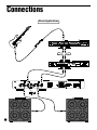
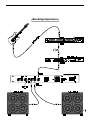
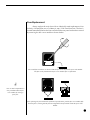
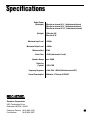
G U I TA R
U
S
E
R
P O W E R
'
S
A M P L I F I E R
M
A
N
U
A
May be covered by one or more of the following:
U.S. Patents #4538297, 4647876, 4696044, 4745309, 4881047, 4893099, 5124657, 5263091, 5268527, 5319713 and 5333201.
Other patents pending. Foreign patents pending.
L
! WARNING !
The Velocity 120 is capable of producing extremely high sound pressure levels. The
use of ear protection is essential in situations when prolonged exposure to such high sound
pressure levels occurs. Failure to use caution and/or ear protection when using this amplifier
may result in permanent hearing impairment or hearing loss. United States Government guidelines concerning safe noise exposure levels should be referred to before operating the amplifier at high levels. The manufacturer is not responsible for any damage resulting from the use
of this product.
®
UNPACKING
Upon unpacking the Velocity® 120, save the carton and all the packing materials in case
it becomes necessary to ship the unit.
Be sure to thoroughly inspect your unit and its carton for any signs of damage that may
have occurred during shipment. If there are any signs of damage, contact your dealer immediately.
INSTALLATION
When installing the Velocity® 120 in your rack, it is best for ventilation and heat dissipation that the unit occupy the bottom space of your rack. It is also recommended that a vacant
space is left above the power amp, if possible, to further improve ventilation.
OPERATING TEMPERATURE
Do not expose this unit to excessively warm or cold temperatures. This unit is designed
to operate between 32°F and 104°F (0°C and 40°C). This unit may not function properly under
extreme conditions.
The lightning flash with arrowhead symbol,
appearing on the rear panel of the unit, is
intended to alert the user of this product of the
presence of uninsulated, dangerous voltage
which may be of sufficient magnitude to
constitute a risk of electric shock.
CAUTION:
CAUTION
RISK OF ELECTRIC SHOCK
DO NOT OPEN
The exclamation point symbol, which appears on
the rear panel of the unit, is intended to alert the
user of this product to the presence of important
operating and maintenance instructions in the
accompanying literature.
TO REDUCE THE RISK OF ELECTRIC SHOCK,
DO NOT REMOVE COVER (OR BACK)
NO USER-SERVICABLE PARTS INSIDE
REFER SERVICING TO QUALIFIED SERVICE PERSONNEL
Copyright ©1994 Rocktron Corporation.
All rights reserved.
Contents
Introduction .................................................................... 1
Front Panel ..................................................................... 2
Rear Panel ...................................................................... 3
Connections ................................................................... 4
Stereo Applications ........................................................................ 4
Mono Bridged Applications ............................................................. 5
Operating Precautions .................................................. 6
Power Output/Speaker Load .......................................................... 6
Fuse Replacement ......................................................................... 7
Unique Features ............................................................ 8
Automatic Short Detection .............................................................. 8
Definition Control............................................................................ 8
Specifications ................................................................ 9
Introduction
Congratulations on your purchase of the Velocity® 120 guitar power
amplifier! Designed to provide maximum reliability under even the most extreme
conditions, the single-rack space Velocity® 120 provides 60 watts per channel stereo
or 120 watts mono-bridged when driving an 8 ohm load.
The 120 incorporates an automatic short-detection circuit which, if a short
should occur, will automatically shut the unit down before any damage can be done
to any of its internal components. Once the problem is detected and corrected, the
unit can be turned back on and will operate normally.
In addition, the amplifier also provides a front panel Definition control for
each channel. This control adjusts a specific pre-defined frequency range which will
allow the guitar to be better distinguished from other instruments when playing with
a band.
This User's Manual details various applications and functions for the
Velocity® 120. After reading it, please keep it for future reference.
1
Front Panel
2
1 POWER switch
This switch powers up the Velocity ® 120.
2 POWER led
When lit, this LED indicates that the Velocity® 120 is powered and
ready for operation.
3 LEVEL control
This control determines the output level for Channel 1.
4 DEFINITION control
This control determines the level of definition for Channel 1. Turning
this control fully counter-clockwise bypasses the Definition circuit,
while turning it fully clockwise provides maximum Definition.
5 LEVEL control
This control determines the output level for Channel 2.
6 DEFINITION control
This control determines the mid frequency content for Channel 2.
Turning this control fully counter-clockwise bypasses the Definition
circuit, while turning it fully clockwise provides maximum Definition.
Rear Panel
1 OUTPUT jacks (Ch. 2)
These standard ¼" jacks provide outputs for Channel
2 to speaker cabinets. Do not connect these outputs to
a load of less than 4 ohms (or less than 8 ohms in
mono-bridged mode). These jacks are inoperable
when using the Velocity® 120 in "bridged" mode (i.e
MONO BRIDGE switch "in").
2 INPUT jack (Ch. 2)
This standard ¼" jack provides an input to Channel 2
from the output of your preamp or the last device in
your effects chain.
This jack is inoperable when using the Velocity® 120 in
"bridged" mode (i.e MONO BRIDGE switch "in").
3 BRIDGED MODE selector switch
When pressed "IN" the Velocity® 120 operates as a
mono unit with increased output power (Channel 2
becomes inoperable in this condition).
In the "OUT" position the unit operates as a normal
stereo amplifier.
4 OUTPUT jacks (Ch. 1)
These standard ¼" jacks provide outputs for Channel
1 to speaker cabinets. Do not connect these outputs to
a load of less than 4 ohms (or less than 8 ohms in
mono-bridged mode). These jacks are the operable
output jacks when using the Velocity® 120 in "bridged"
mode.
5 INPUT jack (Ch. 1)
This standard ¼" jack provides an input to Channel 1
from the output of your preamp or the last device in
your effects chain.
This jack is used as the input jack when operating the
Velocity® 120 in "bridged" mode.
6 POWER INLET module
This module provides a connection for the power cord
and also houses the main fuse of the unit. (For information about changing the fuse, see page 7).
3
Connections
Stereo Applications
4
Mono Bridged Applications
5
Operating Precautions
Although operation of the Velocity® 120 is simple once the proper connections have been made, attention to the following precautions is essential to protect
your equipment against failure and ensure the long life of your Velocity® amplifer.
Power Output/Speaker Load
The Velocity® 120 is capable of producing the following power output
levels into each of these loads:
Unbridged (Stereo)
Due to the efficiency of the
Velocity® 120 design, there is
not a large variance in output
level when comparing various
impedance loads.
Bridged (Mono)
(with both channels driven)
4Ω load
8Ω load
16Ω load
60 watts
50 watts
30 watts
4Ω load* (Not Recommended)
8Ω load
120 watts
16Ω load
95 watts
* Note: Rocktron does not recommend using the Velocity 120 in bridged mode when
connected to a load of less than 8 ohms. However, using the Velocity 120 in
bridged mode with an 8 ohm load produces the same output level (120 watts)
as would be achieved with a 4 ohm load - therefore using a 4 ohm load would
provide no additional benefits.
!
Always be certain to use speakers or speaker cabinets capable of
withstanding the power provided in the above mentioned applications.
Rocktron is not responsible for speaker failure resulting from use of this
equipment.
!
Never connect 2 outputs of the amplifier to the same speaker. This
would be equivalent to shorting the outputs of the amplifier together
and would shut the unit down immediately.
6
Fuse Replacement
Always replace the main fuse with an identically rated replacement. Your
Velocity® 120 amplifier uses a 5x20mm, 4 amp, 250V slow-blow fuse. The fuse is
located immediately below the line cord inlet on the rear panel and can be accessed
by removing the fuse cover module as shown below.
Use a small flat screwdriver as shown to slide the fuse cover out from the power inlet module.
The fuse can be found inside the fuse cover module after it is pulled out.
G
Note: A small compartment is
also provided within the fuse
cover module for storing a
spare fuse.
After replacing the fuse with another of identical specifications, push the fuse cover module fully
back into place, ensuring that the fuse has snapped onto the fuse holder inside the power inlet
module.
7
Unique Features
Automatic Short Detection
A feature truly unique to the Velocity® 120 is its Automatic Short Detection
circuit. Typically, shorting the outputs of a high output power amplifier will cause
amplifier failure and severely damage internal components. The A.S.D. circuit in
the Velocity® 120 will automatically detect any shorts which may inadvertently
occur across the amplifier's outputs and immediately shut down the unit to protect
it against internal damage.
Should this condition occur, switch the unit off for approximately 10
seconds and make sure that the cords from the amplifier outputs are properly
connected. When the power is turned on again with the proper connections, the
amplifier will operate normally. It is important to note that two outputs from the
amplifier should never be connected to the same speaker, as this would be
equivalent to shorting the outputs together and will cause the unit to shut down.
In the unlikely event that the proper connections have been made and the
unit still shuts down, we strongly recommend that you first contact our Customer
Support Department at the phone or fax number shown on the back cover of this
manual before taking the unit to a dealer or repair shop for servicing.
Definition Control
It often becomes a problem when playing with other musicians that the
guitar can get "buried" under the other instruments and cannot be distinguished
easily. The front panel Definition control gives the effect of bringing the guitar out
of the cabinet so that it can be heard despite the other instruments. Although it does
not actually affect the volume of the amplifier, the Definition control can be
adjusted so that the guitar becomes more audible when playing with a band.
Turning the Definition Control fully counter-clockwise bypasses the definition circuit, while turning it fully clockwise provides maximum definition.
8
Specifications
Output Power
(Unbridged)
(Bridged)
60 watts per channel @ 4Ω (both channels driven)
50 watts per channel @ 8Ω (both channels driven)
30 watts per channel @ 16Ω (both channels driven)
120 watts @ 8Ω
95 watts @ 16Ω
Maximum Input Level
+22dBu
Maximum Output Level
+30dBu
Maximum Gain
Noise Floor
37dB
-81dB (referenced to 1 watt)
Dynamic Range
over 100dB
Distortion
(Typical)
.015% THD
Frequency Response
±1dB, 20Hz - 20KHz (Definition control OFF)
Current Consumption
450 watts, 3.75 amps @120VAC
Rocktron Corporation
2870 Technology Drive
Rochester Hills, MI 48309
Customer Service: (810) 853-5150
Fax Number:
(810) 853-5937
9