1
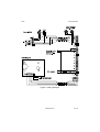
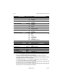
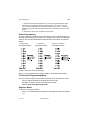
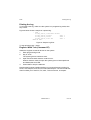
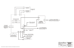
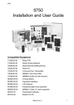
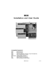
9449
Installation and User Guide
Compatible Equipment
9427
9040
660
8440/8400
9056
Remote Keypad
Internal Sounder
Speech communicator
Communicator
Redcare STU (Manufactured by others)
496329 Issue 1
1 of 16
9449
INTRODUCTION
The 9449 is a fully programmable 8 zone alarm system control unit with Full
and Part Set, designed for domestic and small commercial installations.
The control unit comprises a single printed circuit board, with microprocessor
electronics, mounted in a steel box with a slide off lid. Up to four 9427 remote
keypads can be connected to the control unit.
Technical Description
Specification
Operating temperature
= -10º to +55ºC.
Humidity
= 96% RH.
Dimensions
= h x w x d 234 x 243 x 87 mm.
Weight
= Approx 3.0 kg (without stand-by battery).
Conforms to EN50131-1 Grade 1 and 2 and current BS4737 Part 1 for
remote signalled systems, ACPO-IAS Policy, NACOSS NACP14, ABI log
requirements.
Power Supply
System power supply
Control unit power
9427 Remote Keypad
Standby Battery
= 230VAC (Ambient Temp. 20 º. C) 1A total.
= 50mA nominal quiescent, 150mA active.
= 20mA quiescent with keypad backlight on.
= 12 Volt, 7AH rechargeable lead-acid, Gel
Type battery (not supplied).
Conforms to EN50131-6 Type A power supply for Grade 1 and 2 systems.
Outputs
Bell, Strobe, O/P and AUX are open collector transistor outputs.
Bell
= 500mA, 12VDC. negative applied.
Strobe
= 500mA, 12VDC. negative applied.
O/P
= 100mA, 12VDC. negative applied.
LS
= can support two parallel connected externally mounted 16ý loudspeakers for internal
sounder or EE tones. Controlled by Vol.
potentiometer.
AUX (for detectors)
= 500mA, 12VDC.
Coms OP1-4
= 12V logic outputs, -ve applied in alarm (+ve
removed).
2 of 16
496329 Issue 1
9449
Inputs
Inputs
Tellback/RedCare reset
Line Fault input
= +12V applied to operate reset.
= +12V applied to indicate line failure.
Fuses
F1 - Battery
= 2A Anti Surge.
F2 - 12V AUX
= 1A Fast.
F3 - 21 VAC
= 2A Anti Surge.
Caution: When replacing fuses use the ratings quoted above.
Connecting a 9427 Remote Keypad
Figure 1. 9427 Keypad Connections
Keypad Addressing
The 9449 control unit is supplied with one remote keypad. If you have fitted
more keypads then each one must be given a separate "address". Links LK1
to LK3 set the keypad address, as shown in Figure 2.
496329 Issue 1
3 of 16
Wiring Example
9449
Figure 2. Keypad Addressing.
Keypad Backlight
When supplied from the factory the control unit is configured with the keypad
backlight ON. To turn the keypad backlight OFF remove the jumper from link
LK4, shown in Figure 2.
Wiring Example
Figure 3 shows an example system wired for two detectors. Note that mains
and battery connections are not shown.
Notes:
1. Power for detectors is available from two terminals on the control unit PCB
marked "+ - 12V AUX".
2. If you are not using an SAB, or wish to test the control unit with no SAB
connected, you must link 0V and TR on the control unit PCB.
4 of 16
496329 Issue 1
9449
Wiring Example
Figure 3. Wiring Example
496329 Issue 1
5 of 16
Connecting a Communicator
9449
Connecting a Communicator
Figure 4. Communications Wiring Harness.
PROGRAMMING
Initial Start Up
Before applying power to the control unit, ensure that any remote keypad(s),
all zone circuits and sounders are connected.
1. Connect the battery to the control unit PCB.
The green power LED flashes and the internal sounder may sound.
Ignore any other lights.
2. Key-in the factory default user access code: 1234.
The internal sounder stops. Ignore any other lights.
3. Please fit the case lid before applying mains power (this also defeats
the tamper switch). Make sure the green earth wire is connected to the
upper left hand support pillar on the case back.
4. Apply mains power.
The Power LED glows steadily.
5.
Key-in 0 then # followed by the factory default engineer access code:
7890. (You do not have to remove the control unit lid.)
All LEDs, except for Power, Fault and Service, flash.
You are now in programming mode.
Programming
When supplied from the factory the control unit is already programmed with a
set of default options, See "Engineer Program Command List".
To change the factory defaults, the system must be in programming mode
(all LEDs flashing). Then:
6 of 16
496329 Issue 1
9449
Engineer Program Command List
1.
Key in a two digit programming command followed by #. (See "Engineer
Program Command List".)
One or more LEDs glow to show you the current option used in the
command. While in programming mode use the blue numbers
printed to the right of the LEDs. If all LEDs are OFF the option is "0".
2.
Key in the correct digit for the option you want, and then press #.
The system beeps twice to show that it has accepted the command. All
the LEDs flash, and the system is ready for the next command.
The system gives a single error tone if you enter an incorrect command.
Re-enter the correct command.
3.
Key in "99 #" to leave programming mode when you have finished. You
will then be in user mode.
Engineer Program Command List
To change:
Key-in: Then:
Zone n
0n #x...x #
(see "Zone Programming"
on page 10)
Entry/Exit Chime
Zones omitted in Part Set
Engineer Code
7890
User Code 1
1234
User Code 2
0000
Duress Code
****
Part Set Exit Mode
Notes
Default
n = zone number (1 to 7)
x = Zone type, one or more of:
0 = Not Used (see Note 8)
1 = Normal Alarm
Y
2 = Entry Route
(zone 1 default)
3 = Panic Alarm
4 = Fire
5 = Technical Alarm
6 = Omit Allowed
Y
7 = Chime
8 = 24 Hr Monitored
9 = Double Knock
08 # 7 #
To toggle on/off
Off
10 # zone n..n # LEDs ON for zones
5&6
omitted (see note 1)
20 # new code #
4 digits
21 # new code #
4 digits (see note 2)
22 # new code #
4 digits (see notes 2 & 3)
23 # new code #
4 digits (see notes 2 & 4)
35 # 0 #
1#
Low tone
Silent
496329 Issue 1
Y
7 of 16
Engineer Program Command List
To change:
Auto Re-Arm
9449
Key-in : Then:
40 # 0 #
1#
2#
3#
4#
Bell Delay
41 # 0 #
1#
2#
3#
4#
5#
6#
Bell Time
42 # 1 #
2#
3#
4#
5#
6#
Entry time
43 # 1 #
2#
3#
4#
5#
6#
Exit time
44 # 1 #
2#
3#
4#
5#
6#
Exit Mode
45 # 0 #
1#
Prog O/P
51 # 0 #
1#
Zone 1 in Part Set
52 # 0 #
1#
Part Set Alarm Response
53 # 0 #
1#
2#
Zone 3
54 # 0 #
1#
System Reset
60 # 0 #
1#
Anti Code Reset
61 # 0 #
1#
8 of 16
Notes
Never rearm
Rearm once
Rearm twice
Rearm three times
Always
No delay
90 seconds
3 minutes
5 minutes
10 minutes
15 minutes
20 minutes
90 seconds
3 minutes
5 minutes
10 minutes
15 minutes
20 minutes
10 seconds
20 seconds
30 seconds
45 seconds
1 minute
2 minutes
10 seconds
20 seconds
30 seconds
45 seconds
1 minute
2 minutes
Timed or terminate
Terminate only
PIR set latch
Shock reset
As command 01 (see Note 5)
Entry/Exit
Full Alarm + comms
Local Alarm (bells only)
Internal sounders only
As Command 03 (see Note 6)
Entry/Exit
Engineer
Customer
Disabled
Enabled
496329 Issue 1
Default
Y
Y
Y
Y
Y
Y
Y
Y
Y
Y
Y
Y
9449
To change:
CSID Code
Alarm Abort
Disable Dual Ply Entry
Alarm Confirmation
PA Response
PA Reset
Keys 1 & 3 PA
Comms O/P 1 Type
Comms O/P 2 Type
Comms O/P 3 Type
Comms O/P 4 Type
Line Fault Response
Engineer Program Command List
Key-in: Then: Notes
Default
62 # nnnn #Default 0000
63 # 0 #
Disabled
Y
1#
Enabled
64 # 0 #
Enabled
Y
1#
Disabled
65 # 0 #
Disabled
Y
1#
Enabled
66 # 0 #
Audible
Y
1#
Silent
67 # 0 #
Customer reset
Y
1#
Engineer reset
68 # 0 #
Disabled
Y
1#
Enabled
71 # 0 #
Not used
1#
Fire
Y
2#
PA
3#
Alarm
4#
Open/Close
5#
Alarm Abort
6#
Technical
7#
Alarm Confirmation
72 #
See command 71
PA
73 #
See command 71
Burg
74 #
See command 71
Open/Close
75 # 0 #
Audible
Y
1#
Silent
90 #
See "5. Testing"
96 # date/time
See "5. Testing"
97 # Detectors.
Press * (OMIT) to exit test.
98 #
99 #
(See note 7.)
Print Event Log
Set Clock
Walk Test
Load Defaults
Leave Programming
Notes:
1. n..n = the numbers of the zones. Key the zone number to toggle the zones
on or off. Pressing # stores the zones selected.
2. The end user may change the user codes (see separate user guide).
3. Default user code 2 "0000" is inactive. Changing user code 2 back to "0000"
at any time makes the code inactive again.
4. Default Duress code "****" is inactive. Changing the Duress code back to
"****" at any time makes the code inactive again.
5. If zone 1 is set to PA, Fire, 24Hr or Technical Alarm then the system will give
an error tone if you try to enable this Command.
6. If zone 3 is set to PA, Fire, 24Hr or Technical Alarm then the system will give
an error tone if you try to enable this Command.
496329 Issue 1
9 of 16
Zone Programming
9449
7. If the internal sounder activates when you leave programming then either
the lid tamper, bell tamper, global zone anti tamper, or a 24 hour zone are
open. The zone LEDs glow to show which zone is open. Press *. to return to
programming mode, clear the fault and then key in 99 # again to retun to user
mode.
8. Program any zones not connected as "Not used".
Zone Programming
In order to change zone types you must first set a zone to Not Used (type 0)
and then set it to the type you require. For example, if you wish to re-program
zone 07 from Fire to Normal Alarm with Omit Allow and Chime, proceed as
follows:
1. Key in 07#.
2. Key in 0.
3. Key in 1, 6 and 7.
The display shows:
The display shows:
The display shows:
4. Key in # to store the new zone type.
Zone 7 is now programmed as a Normal Alarm, Omit Allowed and Chime.
To Re-enter Programming Mode
You can re-enter programming mode at any time when the system is unset:
Key-in 0 then # followed by the engineer access code.
All LEDs, except for Power, Fault and Service, flash.
You are now in programming mode.
Engineer Reset
To perform an Engineer Reset:
Key in 0 + # followed by the Engineer’s code (default 7890), and then 99
+ #.
10 of 16
496329 Issue 1
9449
Restoring Factory Defaults
Restoring Factory Defaults (1st stage reset)
The control unit can retain all programmed information and access codes if
both mains and battery power fail. When power is restored the system will
simply need resetting with either the user's or engineer's access code.
However, if the end user or engineer forget their access codes, then:
1. Power down the control unit, mains and battery.
2. Locate the pair of Molex pins marked 'RESET' near the microcontroller.
3. Place a small screwdriver blade to short between the 'RESET' pins.
4. With the blade still across the pins, apply battery power. The keypads
give a double "beep".
5. Remove the screwdriver blade, and then re-apply mains power.
6. Key in 1234.
7. Key in 0 then # followed by 7890.
8. Reprogram the access codes.
Restoring Factory Default Programming (2nd stage reset)
If you wish to restore factory default options, but not engineer and user
codes, then:
1. Enter programming mode (if you are not already there).
2. Key in 98 # at the keypad.
The system loads the factory default command values, erasing all
previously programmed values.
Testing
You may test parts of the system by entering commands at the keypad. To
carry out a test make sure the system is in programming mode and then key
in one of the following commands. Press * (Omit) to end each test:
90 # To print the event log.
97 # To carry out a system walk test. This allows the engineer to test all
alarm devices. While the test is taking place the internal sounder gives
a continuous tone. When a circuit is opened, the sounder gives an
interrupted tone and the appropriate circuit LED lights.
Using the Log
The system keeps a 250 event log of recent events. In the printed log, each
event is stamped with the date (day, month) and time.
496329 Issue 1
11 of 16
Setting the Internal Clock
9449
Setting the Internal Clock (Command 96)
When delivered from the factory the system clock is set to zero. During
installation and testing you must set the clock to the current day, month and
time.
1. Put the system into programming mode.
2. Key in 96 #.
The keypad displays the digits of the date and time one by one on the
zone and tamper LEDs. The keypad sounder beeps each time the
system shows a new digit. The EE zone LED represents "1" and the
Tamper LED represents "9". If all LEDs are off when the keypad beeps
then the digit "0" (zero). Figure 5 below shows an example when the
date is 11 September 3:45pm.
Figure 5. Example Date and Time Display on Keypad
When the keypad has completed showing the date and time, the zone
and tamper LEDs go out, and the system waits for you to enter the new
date and time.
3.
Key in the day, month, hours and minutes in numerical format, and then
press #. (Note that the clock uses 24 hour format for time.)
For example, to change the date and time to 8 August, 1:30 pm, key in
"08 08 13 30 #".
The keypad gives a double beep to show it has accepted the new date
and time, and then returns to programming mode.
12 of 16
496329 Issue 1
9449
Printing the Log
Printing the Log
To print the event log, make sure the system is in programming mode, then
Key in 90 #.
Figure 6 below shows a sample of a printed log.
- 9449 02-Sep, 08:51,
02-Sep, 08:50,
02-Sep, 08:50,
02-Sep, 08:50,
<END OF LOG>
Installer Access
Access
User 1
Alarm
Zone 3
Full Set
User 1
Figure 6. Sample Log Print
To stop printing press * (Omit).
Engineer Walk Test (Command 97)
Allows the engineer to test all devices on the system.
1. Enter programming mode.
2. Key in "97 #".
The system gives a continuous tone.
3.
Open and close each detector contact in turn.
When a detector contact is open the system gives an interrupted tone
and flashes the zone LED.
4. Press OMIT to stop the walk test.
Note that the Engineer's walk test allows you to test all zones including PA
zones, zone tampers, and control unit and bell tampers. The user's walk test
does not allow you to test PA, Fire, 24Hr, Technical zones, or tampers.
496329 Issue 1
13 of 16
9449
Fault Finding
The diagrams on these two pages show typical displays during faults.
14 of 16
496329 Issue 1
9449
Fault Finding
496329 Issue 1
15 of 16
9449
User Commands
Set/Unset System
User code
Omit zone
Zone number + Omit (repeat for all zones to be
omitted) + User code
Keypad PA
1+3
Part Set
2 + ENTER + User code
Test Bells
4 + ENTER + User code
Walk Test
5 + ENTER User code
User code to end test
Change User code
6 + current user code
code to be changed
new user code.
Chime On/Off
7 + ENTER + User code
Read Log
8 + ENTER +User code
<< for earlier events
>> for later events
Set Clock
9 + ENTER + User code + dd + mm + hh + mm +
ENTER
16 of 16
496329 Issue 1