1
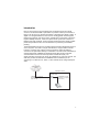
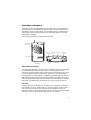
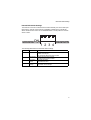
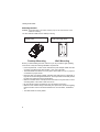
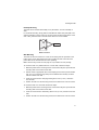
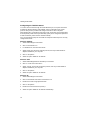
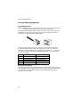
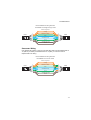
Powered by Accton
EC3002
Media Converter
Installation Guide
www.edge-core.com
Installation Guide
FTTH Media Converter - EC3002
with One Fixed 100BASE-FX Single-Fiber Line Connection,
and One 10BASE-T / 100BASE-TX (RJ-45) Port
EC3002
E062005-R01
150000047700A
Contents
Introduction
Key Features
1
2
Description of Hardware
Fiber Cable Connection
UTP Port
External DIP Switch Settings
Internal DIP Switch Settings
LED Indicators
3
3
3
4
5
6
Installing the FTTH CPE
Package Contents
System Requirements
Mounting the CPE
Desktop Mounting
Wall Mounting
Connecting to the CPE
Making a Connection to the UTP Port
Powering On the CPE
Configuring the TCP/IP Protocol
Windows 95/98/NT
Windows 2000
Windows XP
Mac OS Systems
7
7
7
8
9
9
10
10
11
12
12
12
12
13
Product Specifications
14
Troubleshooting
Diagnosing CPE Indicators
If You Cannot Connect to the Internet
15
15
15
Port and Cable Assignments
RJ-45 Ethernet Port
Straight-Through Wiring
Crossover Wiring
16
16
16
17
EMI Certification
Safety Compliance
FCC - Class B
Warning: Fiber Optic Port Safety
Avertissment: Ports pour fibres optiques - sécurité sur le plan optique
Warnhinweis: Faseroptikanschlüsse - Optische Sicherheit
Wichtige Sicherheitshinweise (Germany)
18
18
18
18
18
18
19
i
Contents
ii
Introduction
Fiber-To-The-Home (FTTH) has always been an attractive option for Internet
access. It has all the benefits of optical fiber. It provides a future-proof network, in
that you do not have to go through the hassles of upgrading from ADSL to xDSL, or
digital co-ax to digital wireless. It does not have to struggle with electromagnetic
interference problems, and with no active “outside-plant” components, it offers the
highest reliability. Moreover, it does not require electric power and is immune to
lightning and other transients. These properties of fiber lead to the lowest possible
power and operational costs, such as maintenance, provisioning and facilities
planning.
The EC3002 Media Converter is an ideal Customer Premises Equipment (CPE) for
an FTTH system. The CPE is a single-channel fiber-to-copper media converter
housed in a compact unit. It allows a service provider to extend an Ethernet
connection over optical fiber directly to a subscriber. The CPE has an embedded (no
external plug/socket) 100BASE-FX full-duplex single-fiber single-mode cable
connection that runs from the service provider’s central office (CO). The
single-mode fiber connection can be run up to distances of 15 km from the CO. The
CPE also provides one standard 10/100BASE-TX RJ-45 Ethernet port for
connecting to a customer’s PC, switch, or other network device using twisted-pair
cable.
Central Office
(CO)
Subscriber’s Home
EC3002 CPE
100BASE-FX full-duplex
single-fiber (WDM) link to CO
(up to 15 km)
10/100BASE-TX UTP
connection to computer
(up to 100 m)
1
Introduction
Key Features
•
•
•
•
•
•
•
•
•
•
•
•
•
•
•
•
2
High-speed Internet access
Optical fiber port supports transmission distances up to 15 km
Built-in transparent bridging between different media segments
Supports 1K MAC addresses — forwards packets only if necessary
Always-on fast optical fiber connection eliminates dial-up delays, providing
transparent Internet access
Auto-negotiating 10/100BASE-TX Ethernet port
Provides DIP switch setting to force 10/100BASE-TX port speed, duplex mode,
and MDI/MDI-X wiring
Internal DIP switch setting for Auto MDI-X, flow control, MAC learning and Link
Pass Through
Compliant to IEEE 10BASE-T, 100BASE-TX, and 100BASE-FX standards
Provides back pressure for half-duplex and IEEE 802.3x flow control for full-duplex
Internal mechanism prevents the fiber connection from being disconnected
accidently
Natural air cooling system without using a fan
LEDs indicate Ethernet activity and fiber link status
Provides device status information for management from the CO
Simple plug-and-play installation
Space-saving compact size
Description of Hardware
The EC3002 is an FTTH CPE product for high-speed Internet access applications.
The CPE includes an embedded fiber cable connection, an RJ-45 Ethernet port, a
DIP-switch for the RJ-45 port settings, an internal DIP switch for Auto MDI-X, flow
control, MAC learning and Link Pass Through, LED status indicators, and an AC
power adapter connection.
The following figure shows the components of the CPE.
EC3002
Vent (Natural Air
Cooling System)
Fiber Line
(embedded)
DIP-Switch
(4 bit)
RJ-45 socket
DC12V Line
(embedded)
LED Indicators
MDI-X
100
Full
Auto
ON
UTP
DC IN 12V
Optical IN/OUT
Top Panel
Rear Panel
Fiber Cable Connection
The single-mode fiber cable connection from the service provider’s CO is embedded
(connected internally) within the CPE. There is no external plug and socket
connection, which prevents the CPE from being disconnected accidently. Also, there
are no configuration settings or maintenance necessary for the fiber cable link.
The single-fiber connection supports a 100BASE-FX full-duplex link to the CO. The
CPE’s fiber transceiver uses Wavelength Division Multiplexing (WDM) technology to
achieve bi-directional operation (1550 nm transmit, 1310 nm receive) over a single
optical fiber. The WDM single-mode fiber link can run up to 15 km from the CO.
UTP Port
The RJ-45 Ethernet port labeled “UTP” operates at 10 or 100 Mbps, and supports
auto-negotiation of speed, duplex mode (i.e., half or full duplex), and flow control.
The UTP port can also be forced to a specific speed and duplex mode via a
DIP-switch setting. Using the DIP switch you can also set the port for MDI or MDI-X
operation, so you can use straight-through cable for all connections.
3
Description of Hardware
External DIP Switch Settings
The CPE has a four-bit DIP switch located on its rear panel next to the UTP port
(see figure below). The DIP switch allows you to enable/disable auto-negotiation for
the UTP port and manually force the speed and duplex mode setting. Also, there is
one switch for setting the UTP port to MDI or MDI-X wiring. The ON position for the
DIP switch is down.
DIP Switch On Position
DIP Switch
MDI-X
100
Full
Auto
ON
UTP
DC IN 12V
Optical IN/OUT
The following table lists the DIP-switch settings:
DIP SW Bit
Name
Description
1
MDI-X
ON: Port wired as MDI-X. (Only functional when Auto is OFF).
OFF: Port wired as MDI.
2
100
ON: Port operating as 100BASE-TX. (Only applies if Auto is OFF.)
OFF: Port operating as 10BASE-T.
3
Full
ON: Full-duplex mode. (Only applies if Auto is OFF.)
OFF: Half-duplex mode.
4
Auto
ON: Auto-negotiation enabled.
OFF: Auto-negotiation disabled. (Force setting using bits 1-3.)
Note: Auto-negotiation must be disabled, i.e., switch Auto (bit 4) set to OFF, for switches
Full (bit 3),100 (bit 2) and MDI-X (bit 1) to be functional.
4
Internal DIP Switch Settings
Internal DIP Switch Settings
The CPE has a second four-bit DIP switch located internally next to the LEDs (see
figure below). This DIP switch sets the capabilities available to the external DIP
switch and allows flow control to be enabled/disabled. The ON position for the DIP
switch is down.
ON
1 2 3 4
The following table lists the Internal DIP switch settings:
DIP SW Bit
Function
Description
1
Auto MDI-X
ON: The external "MDI-X" DIP switch is disabled and Auto MDI-X is
available on the UTP port.
OFF: The external "MDI-X" DIP switch is enabled.
2
MAC learning
disable
ON: MAC learning function is disabled.
OFF: MAC learning function is enabled.
3
Flow Control
disable
ON: Disable flow control.
OFF: Enable flow control.
4
Link Pass
Through
ON: Enable Link Pass Through.
OFF: Disable Link Pass Through.
5
Description of Hardware
LED Indicators
The CPE includes seven LED status indicators on the top panel. The LEDs are
detailed in the following figure and table.
LED
Color
Description
PWR
Green
ON: Power is on.
OFF: Power is off.
OPT
Green
ON: Fiber link is up.
OFF: Fiber link down.
TEST
Orange
ON: Loopback test in progress.
OFF: No loopback test (normal mode).
PC
Green
ON: UTP port link is up.
OFF: UTP port link is down.
DATA
Green
ON/Flashing: UTP port is transmitting or receiving data.
OFF: No activity on the UTP port.
100M
Green
ON: UTP port is operating as 100BASE-TX.
OFF: UTP port is operating as 10BASE-T.
FULL
Green
ON: UTP port is operating in full-duplex mode.
OFF: UTP port is operating in half-duplex mode.
6
Package Contents
Installing the FTTH CPE
Before installing the CPE, verify that you have all the items listed under “Package
Contents.” If any of the items are missing or damaged, contact your service provider.
Also, be sure you have all the necessary tools and cabling before installing the CPE.
Package Contents
The package includes the following items:
•
•
•
•
One EC3002 FTTH media converter CPE
Four rubber foot pads
AC power adapter
This Installation Guide
Please inform your service provider if there are any incorrect, missing or damaged
parts. If possible, retain the carton, including the original packing materials. Use
them again to repack the product in case there is a need to return it for repair.
System Requirements
The CPE requires the following computer features to operate:
• A PC or Macintosh with a 10/100 Mbps Ethernet adapter card installed
• For Internet access, the computer must be configured for TCP/IP
7
Installing the FTTH CPE
Mounting the CPE
Caution: The EC3002 CPE is for indoor mounting only. Do not mount the unit on the
outside of a building.
The CPE includes rubber feet for desktop mounting.
Horizontal mounting using
rubber feet
Desktop Mounting
Wall mounting using the
wall-mounting slots
Wall Mounting
Before you start installing the CPE, make sure you can provide the right operating
environment. Verify the following installation requirements:
• Power requirements: 12 VDC via the included AC power adapter. Make sure that
a properly grounded power outlet is within 1.8 m (6 ft) of the CPE.
• The CPE should be located in a cool dry place, with at least 5 cm (2 in.) of space
on all sides for proper air flow.
• Place the CPE out of direct sunlight, and away from heat sources or areas with a
high amount of electromagnetic interference. The temperature and humidity should
be within the ranges listed in the specifications.
• Make sure the fiber line is carefully routed to the CPE in a way that does not incur
a bending radius in the cable of less than 30 mm.
• Be sure that the CPE is accessible for the UTP Ethernet connection.
• Make sure UTP cable is always routed away from power lines, fluorescent lighting
fixtures and other sources of electrical interference such as radios, transmitters,
etc.
• The status LEDs are clearly visible.
8
Mounting the CPE
Desktop Mounting
The CPE can be mounted horizontally on any flat surface, such as a desktop or
shelf.
For horizontal mounting, simply stick the self-adhesive rubber foot pads (that come
with this package) on each of the four concave spaces located on the bottom of the
CPE. Then, place the CPE on the flat surface where it is to be installed.
Rubber feet
Bottom surface
Wall Mounting
The CPE can also be mounted on a wall. Two mounting slots are provided on the
bottom of the unit for this purpose. Be sure to position the CPE so that the front
panel LEDs can be viewed when the unit is operating.
Note: Wall mounting screws and wall plugs are not provided in the CPE package.
To mount the CPE on a plastered brick or concrete wall, follow these steps:
1. Mark the position of the mounting screws on the wall so they line up with the two
mounting slots on the bottom of the CPE.
2. Drill two holes of appropriate size for the wall plugs and screws (recommended
size T3 x 15L). Press the plugs firmly into the drilled holes until they are flush
with the surface of the wall.
3. Insert the screws into the wall plugs leaving about 3 mm (0.12 in.) clearance
from the wall.
4. Position the CPE over the mounting screws, then slide it down onto the screws.
To mount the CPE on a wood wall, follow these steps:
1. Mark the position of the mounting screws on the wall so they line up with the two
mounting slots on the bottom of the CPE.
2. Insert the screws into the wall leaving about 3 mm (0.12 in.) clearance from the
wall.
3. Position the CPE over the mounting screws, then slide it down onto the screws.
9
Installing the FTTH CPE
Connecting to the CPE
Caution: The CPE fiber line should be connected to the unit by a qualified technician
only. Do not attempt to remove the fiber cable from the CPE. If there are any
problems with the fiber cable connection, contact your service provider.
You can connect any computer with an Ethernet network interface card, a LAN
switch, hub, or other network device to the CPE’s UTP port.
FTTH Link
Computer
EC3002
Fiber Line
UTP
Port
AC Power Outlet
AC Power Adapter
Category 5 UTP cable to
Ethernet port on computer
DC Power Cord
Making a Connection to the UTP Port
The UTP port on the CPE supports both MDI and MDI-X operation via DIP-switch
selection. This allows you to use standard straight-through twisted-pair cables to
connect to any other network device (computers, switches, routers, or hubs).
See “Port and Cable Assignments” on page 16 for more information on connecting
straight-through or crossover UTP cables to MDI or MDI-X ports.
Caution: Do not plug a phone jack connector into any RJ-45 port. This may damage the
CPE. Instead, use only twisted-pair cable with RJ-45 connectors that conform
with FCC standards.
To connect the CPE’s UTP port directly to a computer, carry out the following steps:
1. Prepare the computer you wish to connect. Make sure you have installed a
10BASE-T or 100BASE-TX network interface card for connecting to the CPE’s
UTP port.
2. Check that the CPE’s UTP port has auto-negotiation enabled by setting the
“Auto” DIP-switch to ON. If you manually set the speed and duplex mode, be
sure that the CPE and computer’s network interface card settings match.
3. Check that the CPE’s UTP port has MDI-X enabled by setting the “MDI-X”
DIP-switch to ON. Prepare straight-through shielded or unshielded twisted-pair
cable with RJ-45 plugs at both ends (not included in the CPE package). Use
100-ohm Category 3, 4 or 5 cable for 10 Mbps Ethernet connections, or
100-ohm Category 5 cable for 100 Mbps Fast Ethernet connections.
10
Powering On the CPE
4. Connect one end of the cable to the RJ-45 port of the computer’s network
interface card, and the other end to the UTP port on the CPE. When inserting an
RJ-45 plug, be sure the tab on the plug clicks into position to ensure that it is
properly seated.
Notes: 1. Make sure each twisted-pair cable does not exceed 100 meters (328 feet).
2. We advise using Category 5 cable for all network connections to avoid any
confusion or inconvenience in the future when you upgrade devices to Fast
Ethernet.
Powering On the CPE
Plug the AC power adapter directly into a power outlet. Check the LED marked
“Power” on the front panel to be sure it is on.
11
Installing the FTTH CPE
Configuring the TCP/IP Protocol
To connect to the Internet through the CPE’s Ethernet port, a computer must have
an Ethernet network interface card installed, and be configured for the TCP/IP
protocol. Many service providers will configure TCP/IP for client computers
automatically using a networking technology known as Dynamic Host Configuration
Protocol (DHCP). Other service providers may specify an IP configuration (known as
a static IP address), which must be entered manually.
Carry out the following steps to check that the computer’s Ethernet port is correctly
configured for DHCP.
Windows 95/98/NT
1. Select Start/Settings/Control Panel.
2. Click on the Network icon.
3. For Windows NT, click the Protocols tab.
4. Select TCP/IP from the list of network protocols, this may include details of
adapters installed in your computer.
5. Click on “Properties.”
6. Select the option “Obtain an IP Address.”
Windows 2000
1. Select Start/Settings/Network and Dial-up Connections.
2. Click on “Local Area Connections.”
3. Select “TCP/IP” from the list of network protocols, this may include details of
adapters installed in your computer.
4. Click on “Properties.”
5. Select the option “Obtain an IP Address.”
Windows XP
1. Select Start/Settings/Control Panel.
2. Click on the Network and Internet Connections icon.
3. Double click “LAN or High-Speed Internet.”
4. Click on “Properties.”
5. Double click “Internet Protocol (TCP/IP).”
6. Select the option “Obtain an IP Address automatically.”
12
Mac OS Systems
1. Pull down the Apple Menu. Click “Control Panels” and select “TCP/IP.”
2. In the TCP/IP dialog box, make sure that “Ethernet” is selected in the “Connect
via:” field.
3. If “Using DHCP Server” is already selected in the “Configure” field, your
computer is already configured for DHCP. Otherwise, select “Using DHCP
Server” in the “Configure” field and close the window.
4. Another box will appear asking whether you want to save your TCP/IP settings.
Click Save.
Your service provider will now be able to automatically assign an IP address to your
computer.
13
Product Specifications
Product Specifications
Standards Conformance
Fiber Specifications
Fiber Cable
Connector
Wavelengths
Data Rate
Transmit Power
Receive Power
Optical Power Budget
Range
Ports
Media Connection
LEDs
IEEE 802.3 10BASE-T, IEEE 802.3u 100BASE-TX and
100BASE-FX, IEEE 802.3x flow control
TTC Standard TS-1000 class S
ITU-T G.652 single-fiber single-mode (WDM)
SC and splice (internal)
1310 nm transmit, 1550 nm receive
100 Mbps full duplex
-14 to -8 dBm
-30 to -8 dBm
16 dB
Up to 15km (max)
1 RJ-45 10/100BASE-TX
10BASE-T: Cat 3, 4, or 5 UTP cable
100BASE-TX: Cat 5 UTP cable
Power, Test, OPT (Fiber), PC (LAN), Data (LAN
Activity), 100 (LAN speed), FULL (LAN mode)
18 x 11 x 3.5 cm (7.09 x 4.33 x 1.38 in.)
Dimensions
Weight
Media Converter
250 g (8.82 oz.) maximum
AC Adapter
160 g (5.64 oz.) maximum
Input Power
12 VDC, 1A (via AC power adapter)
Available Adapters: Europe - DVE / DV-0151A-12A(U)
Japan and USA - DVW / DV-0151A-12
Power Consumption
4 Watts maximum
Environmental
Temperature
Operating: 0~40 °C / 32~122 °F
Storage: -10~70 °C / -40~158 °F
Humidity
10 - 90% (non-condensing)
Certification
Immunity
IEC 61000-4-2
Emissions
FCC Class B
14
Diagnosing CPE Indicators
Troubleshooting
Diagnosing CPE Indicators
The FTTH CPE can be easily monitored through panel indicators to identify
problems. The table below describes common problems you may encounter and
possible solutions.
Symptom
Cause
Solution
Power indicator does Power outlet, or external • Check the power outlet by plugging in another device
not light up after power AC power adapter may
that is functioning properly.
on.
be defective.
• Contact your FTTH service provider.
PC indicator does not Network interface (e.g., a • Verify that the CPE and computer are powered on.
light up after making a network adapter card in
connection.
the attached computer), • Be sure the cable is plugged into both the CPE and
the computer.
network cable, or CPE
UTP port may be
• Verify that the proper cable type is used and its length
defective.
does not exceed specified limits.
• Check the network adapter in the computer and
cable connections for possible defects. Replace the
defective cable if necessary.
OPT indicator does not The CPE is not powered • Verify that the CPE is powered on.
light up after power on. on, the link is down at the
• Be sure the fiber cable splice and SC connector are
Central Office, or fiber
connected correctly in the CPE.
cable may be defective.
• Verify that the fiber cable length does not exceed
specified limits.
• Contact your FTTH service provider.
If You Cannot Connect to the Internet
• Check that the attached computer is properly configured for TCP/IP. See
“Configuring the TCP/IP Protocol” on page 12.
• Make sure the correct network adapter driver is installed for the computer
operating system. If necessary, try reinstalling the driver.
• Check if the network adapter’s speed or duplex mode has been configured
manually. Note that we recommend setting the adapter to auto-negotiation when
installing the network driver.
15
Port and Cable Assignments
Port and Cable Assignments
RJ-45 Ethernet Port
Caution: DO NOT plug a phone jack connector into any RJ-45 port. Use only twisted-pair
cables with RJ-45 connectors that conform with FCC standards.
An Ethernet twisted-pair link segment requires two pairs of wires. Each wire pair is
identified by two different colors. Each wire pair must be attached to the RJ-45
connector in a specific orientation detailed below.
The RJ-45 Ethernet port on the FTTH CPE can be set as an MDI or MDI-X port,
which allows straight-through cable to be used for a connection to a computer,
switch/hub, or other network device. In straight-through cable, pins 1, 2, 3 and 6 at
one end of the cable, are connected straight-through to pins 1, 2, 3 and 6 at the
other end of the cable.
Pin
MDI-X Signal Name
MDI Signal Name
1
Receive Data plus (RD+)
Transmit Data plus (TD+)
2
Receive Data minus (RD-)
Transmit Data minus (TD-)
3
Transmit Data plus (TD+)
Receive Data plus (RD+)
6
Transmit Data minus (TD-)
Receive Data minus (RD-)
4,5,7,8
Not used
Not used
Straight-Through Wiring
If the twisted-pair cable is to join two ports and only one of the ports has an internal
crossover (MDI-X), the two pairs of wires must be straight-through. (The CPE RJ-45
port can be forced to either MDI or MDI-X for using straight-thorough cable to
connect to a PC or switch.)
16
RJ-45 Ethernet Port
EIA/TIA 568B RJ-45 Wiring Standard
10/100BASE-TX Straight-through Cable
White/Orange Stripe
Orange
End A
1
2
3
4
5
6
7
8
White/Green Stripe
Blue
White/Blue Stripe
Green
White/Brown Stripe
1
2
3
4
5
6
7
8
End B
Brown
Crossover Wiring
If the twisted-pair cable is to join two ports and either both ports are labeled with an
“X” (MDI-X) or neither port is labeled with an “X” (MDI), a crossover must be
implemented in the wiring.
EIA/TIA 568B RJ-45 Wiring Standard
10/100BASE-TX Crossover Cable
White/Orange Stripe
Orange
End A
1
2
3
4
5
6
7
8
White/Green Stripe
Blue
White/Blue Stripe
Green
White/Brown Stripe
1
2
3
4
5
6
7
8
End B
Brown
17
EMI Certification
EMI Certification
Safety Compliance
FCC - Class B
This equipment generates, uses, and can radiate radio frequency energy and, if not
installed and used in accordance with the instruction manual, may cause
interference to radio communications. It has been tested and found to comply with
the limits for a Class B computing device pursuant to Subpart B of Part 15 of FCC
Rules, which are designed to provide reasonable protection against such
interference when operated in a commercial environment. Operation of this
equipment in a residential area is likely to cause interference, in which case the
user, at his own expense, will be required to take whatever measures may be
required to correct the interference. You are cautioned that changes or modifications
not expressly approved by the party responsible for compliance could void your
authority to operate the equipment.
You may use unshielded twisted-pair (UTP) for RJ-45 connections - Category 3 or
greater for 10 Mbps connections, and Category 5 for 100 Mbps connections, and
Category 5 or 5e for 1000 Mbps connections. For fiber optic connections, you may
use 50/125 or 62.5/125 micron multimode fiber or 9/125 micron single-mode fiber.
Warnings: 1. Wear an anti-static wrist strap or take other suitable measures to prevent electrostatic
discharge when handling this equipment.
2. When connecting this switch to a power outlet, connect the field ground lead on the
tri-pole power plug to a valid earth ground line to prevent electrical hazards.
Warning: Fiber Optic Port Safety
When using a fiber optic media expansion module, never look at the
transmit laser while it is powered on. Also, never look directly at the fiber
TX port and fiber cable ends when they are powered on.
Avertissment: Ports pour fibres optiques - sécurité sur le plan optique
Ne regardez jamais le laser tant qu’il est sous tension. Ne regardez
jamais directement le port TX (Transmission) à fibres optiques et les
embouts de câbles à fibres optiques tant qu'ils sont sous tension.
Warnhinweis: Faseroptikanschlüsse - Optische Sicherheit
Niemals ein Übertragungslaser betrachten, während dieses
eingeschaltet ist. Niemals direkt auf den Faser-TX-Anschluß und auf die
Faserkabelenden schauen, während diese eingeschaltet sind.
18
Wichtige Sicherheitshinweise (Germany)
Wichtige Sicherheitshinweise (Germany)
1.
2.
3.
4.
5.
6.
7.
8.
9.
10.
11.
12.
13.
14.
Bitte lesen Sie diese Hinweise sorgfältig durch.
Heben Sie diese Anleitung für den späteren Gebrauch auf.
Vor jedem Reinigen ist das Gerät vom Stromnetz zu trennen. Verwenden Sie keine
Flüssigoder Aerosolreiniger. Am besten eignet sich ein angefeuchtetes Tuch zur Reinigung.
Die Netzanschlu ßsteckdose soll nahe dem Gerät angebracht und leicht zugänglich sein.
Das Gerät ist vor Feuchtigkeit zu schützen.
Bei der Aufstellung des Gerätes ist auf sicheren Stand zu achten. Ein Kippen oder Fallen
könnte Beschädigungen hervorrufen.
Die Belüftungsöffnungen dienen der Luftzirkulation, die das Gerät vor Überhitzung schützt.
Sorgen Sie dafür, daß diese Öffnungen nicht abgedeckt werden.
Beachten Sie beim Anschluß an das Stromnetz die Anschlußwerte.
Verlegen Sie die Netzanschlußleitung so, daß niemand darüber fallen kann. Es sollte auch
nichts auf der Leitung abgestellt werden.
Alle Hinweise und Warnungen, die sich am Gerät befinden, sind zu beachten.
Wird das Gerät über einen längeren Zeitraum nicht benutzt, sollten Sie es vom Stromnetz
trennen. Somit wird im Falle einer Überspannung eine Beschädigung vermieden.
Durch die Lüftungsöffnungen dürfen niemals Gegenstände oder Flüssigkeiten in das Gerät
gelangen. Dies könnte einen Brand bzw. elektrischen Schlag auslösen.
Öffnen sie niemals das Gerät. Das Gerät darf aus Gründen der elektrischen Sicherheit nur
von authorisiertem Servicepersonal geöffnet werden.
Wenn folgende Situationen auftreten ist das Gerät vom Stromnetz zu trennen und von einer
qualifizierten Servicestelle zu überprüfen:
a.
Netzkabel oder Netzstecker sind beschadigt.
b.
Flüssigkeit ist in das Gerät eingedrungen.
c.
Das Gerät war Feuchtigkeit ausgesetzt.
d.
Wenn das Gerät nicht der Bedienungsanleitung entsprechend funktioniert oder Sie mit Hilfe
e.
Das Gerät ist gefallen und/oder das Gehäuse ist beschädigt.
f.
Wenn das Gerät deutliche Anzeichen eines Defektes aufweist.
dieser Anleitung keine Verbesserung erzielen.
15. Zum Netzanschluß dieses Gerätes ist eine geprüfte Leitung zu verwenden. Für einen
Nennstrom bis 6A und einem Gerätegewicht größer 3kg ist eine Leitung nicht leichter als
H05VV-F, 3G, 0.75mm2 einzusetzen.
Der arbeitsplatzbezogene Schalldruckpegel nach DIN 45 635 Teil 1000 beträgt 70dB(A) oder
weniger.
19
EMI Certification
20
EC3002
E062005-R01
150000047700A