1
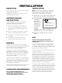
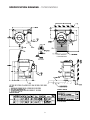
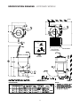
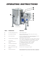
Operators Manual
Installation, Operation & Service
Gas 25 Gallon Kettle
MODELS:
KGL-25
KGL-25-T
KGT-25
KGT-25-T
1333 East 179th St., Cleveland, Ohio, U.S.A. 44110
Enodis
Phone: (216) 481-4900 Fax: (216) 481-3782
Visit our web site at www.clevelandrange.com
SE95052
FOR THE USER
IMPORTANT!
ENSURE KETTLE IS AT ROOM TEMPERATURE AND
PRESSURE GAUGE IS SHOWING ZERO OR LESS PRESSURE
PRIOR TO REMOVING ANY FITTINGS.
FOR YOUR SAFETY
DO NOT STORE OR USE
GASOLINE OR ANY OTHER
FLAMMABLE LIQUIDS AND
VAPOURS IN THE VICINITY
OF THIS OR ANY OTHER
APPLIANCE.
WARNING: Improper installation,
adjustment, alteration, service or
maintenance can cause property
damage, injury or death. Read the
installation operating and
maintenance instructions
thoroughly before installing or
servicing this equipment.
IMPORTANT
POST IN A PROMINENT LOCATION, INSTRUCTIONS TO BE FOLLOWED IN THE EVENT
THE USER SMELLS GAS. THIS INFORMATION SHALL BE OBTAINED BY CONSULTING
YOUR LOCAL GAS SUPPLIER.
KEEP APPLIANCE AREA FREE AND CLEAR FROM COMBUSTIBLES.
DO NOT OBSTRUCT THE FLOW OF COMBUSTION AND VENTILATION AIR.
ALL SERVICE MUST BE PERFORMED BY A QUALIFIED CLEVELAND RANGE
TECHNICIAN.
RETAIN THIS MANUAL FOR YOUR REFERENCE.
TABLE OF CONTENTS
Installation
Inspection . . . . . . . . . . . . . . . . . . . . . . . . . . . . . . . . . . . . . . . . . . . . 1
Shipping Damage Instructions. . . . . . . . . . . . . . . . . . . . . . . . . . . . . 1
General. . . . . . . . . . . . . . . . . . . . . . . . . . . . . . . . . . . . . . . . . . . . . . . 1
Clearance Requirements . . . . . . . . . . . . . . . . . . . . . . . . . . . . . . . . . 1
Installation . . . . . . . . . . . . . . . . . . . . . . . . . . . . . . . . . . . . . . . . . . . . 1
Gas . . . . . . . . . . . . . . . . . . . . . . . . . . . . . . . . . . . . . . . . . . . . . . . . . . 1
Electrical . . . . . . . . . . . . . . . . . . . . . . . . . . . . . . . . . . . . . . . . . . . . . 2
Ventilation. . . . . . . . . . . . . . . . . . . . . . . . . . . . . . . . . . . . . . . . . . . . . 2
Water . . . . . . . . . . . . . . . . . . . . . . . . . . . . . . . . . . . . . . . . . . . . . . . . 2
Installation Checks. . . . . . . . . . . . . . . . . . . . . . . . . . . . . . . . . . . . . . 2
Cleaning . . . . . . . . . . . . . . . . . . . . . . . . . . . . . . . . . . . . . . . . . . . . . . 2
Specification Drawing . . . . . . . . . . . . . . . . . . . . . . . . . . . . . . . . . 3-4
Operating Instructions
General Parts Drawing . . . . . . . . . . . . . . . . . . . . . . . . . . . . . . . . . . 5
Operating the Kettle. . . . . . . . . . . . . . . . . . . . . . . . . . . . . . . . . . . . . 6
Approximate Boiling Times . . . . . . . . . . . . . . . . . . . . . . . . . . . . . . . 6
Cleaning Instructions
Care & Cleaning . . . . . . . . . . . . . . . . . . . . . . . . . . . . . . . . . . . . . . . 7
Recommended Cleaners . . . . . . . . . . . . . . . . . . . . . . . . . . . . . . . . . . 7
Service Parts
Warranty . . . . . . . . . . . . . . . . . . . . . . . . . . . . . . . . . . . . . . . . . . . . . . 8
Faucet Assembly. . . . . . . . . . . . . . . . . . . . . . . . . . . . . . . . . . . . . . . . 8
Component Mounting Plate . . . . . . . . . . . . . . . . . . . . . . . . . . . . . . . 9
Burner Assembly . . . . . . . . . . . . . . . . . . . . . . . . . . . . . . . . . . . . . . 10
2" Tangent Draw-Off Valve . . . . . . . . . . . . . . . . . . . . . . . . . . . . . . 11
General Assembly - Tilting Models . . . . . . . . . . . . . . . . . . . . . 12-14
- Stationary Models. . . . . . . . . . . . . . . . . . . 15-16
Console Controls . . . . . . . . . . . . . . . . . . . . . . . . . . . . . . . . . . . . . . 17
Hinge Assembly . . . . . . . . . . . . . . . . . . . . . . . . . . . . . . . . . . . . . . . 18
Maintenance
Inspection & Maintenance Check List . . . . . . . . . . . . . . . . . . . . . 19
Safety Inspection Checklist . . . . . . . . . . . . . . . . . . . . . . . . . . . . 20-21
- Safety Valve . . . . . . . . . . . . . . . . . . . . . . . . . . . . . . . . . . . . . . . 20
- Safety Thermostat . . . . . . . . . . . . . . . . . . . . . . . . . . . . . . . . . . 21
- Low Water Probe . . . . . . . . . . . . . . . . . . . . . . . . . . . . . . . . . . . 21
- Operating Thermostat . . . . . . . . . . . . . . . . . . . . . . . . . . . . . . . 21
Lubrication Procedure . . . . . . . . . . . . . . . . . . . . . . . . . . . . . . . . . . 22
Hinge Adjustment Instructions. . . . . . . . . . . . . . . . . . . . . . . . . . . . 22
Calibrating Procedure . . . . . . . . . . . . . . . . . . . . . . . . . . . . . . . . . . 23
Pressure Relief Valve Periodic Testing Procedure. . . . . . . . . . . . . 23
Reservoir Fill Procedures . . . . . . . . . . . . . . . . . . . . . . . . . . . . . . . 24
Kettle Jacket Filling & Draining Procedures . . . . . . . . . . . . . . . . 25
Kettle Venting Instructions . . . . . . . . . . . . . . . . . . . . . . . . . . . . . . . 26
Vacuum Leak Test . . . . . . . . . . . . . . . . . . . . . . . . . . . . . . . . . . . . . . 26
Repairing Leaks in Steam Jacketed Kettle Fittings . . . . . . . . . . . . 27
Wiring Diagram . . . . . . . . . . . . . . . . . . . . . . . . . . . . . . . . . . . . . . . 27
Sequences of Operation . . . . . . . . . . . . . . . . . . . . . . . . . . . . . . 28-31
Symbol Legend . . . . . . . . . . . . . . . . . . . . . . . . . . . . . . . . . . . . . 32-33
INSTALLATION
INSPECTION
INSTALLATION
Before unpacking visually inspect the unit for evidence
of damage during shipping.
Note: For clearance requirements, suggested
drain location and assembly details refer to
"SPECIFICATION DRAWING" on page #3.
If damage is noticed, do not unpack the unit, follow
shipping damage instructions.
1. Position the unit in it's permanent location, and
level the unit by turning the adjustable feet.
SHIPPING DAMAGE
INSTRUCTIONS
2. Once positioned
4 7/8" (124mm)
and leveled,
120
120
permanently
secure the unit's
7/16"Ø, 3 HOLES
flanged feet to
ON 3 1/8" (80mm) B.C.D.
the floor using
FLANGED FOOT DETAIL
5/16" lag bolts
(REAR LEGS ONLY
and floor
anchors
(supplied by the installer). Three bolts are
required to secure each of the flanged feet.
If shipping damage to the unit is discovered or
suspected, observe the following guidelines in
preparing a shipping damage claim.
1. Write down a description of the damage or the
reason for suspecting damage as soon as it is
discovered. This will help in filling out the claim
forms later.
)
2. As soon as damage is discovered or suspected,
notify the carrier that delivered the shipment.
3. Seal joints of flanged feet with a silicone
sealant.
3. Arrange for the carrier's representative to examine
the damage.
GAS
4. Fill out all carrier claims forms and have the
examining carrier sign and date each form.
ENSURE THE GAS SUPPLY MATCHES THE
KETTLE'S REQUIREMENTS AS STATED ON THE
RATING PLATE.
GENERAL
It is recommended that a sediment trap (drip leg) be
installed in the gas supply line. If the gas pressure
exceeds 14” water column, a pressure regulator must
be installed, to provide a maximum of 14” water column
gas pressure to the gas control valve.
Installation of the kettle must be accomplished by
qualified installation personnel working to all applicable
local and national codes. Improper installation of
product could cause injury or damage.
Connect the gas line to the manual valve located at the
rear of the control box.
This equipment is built to comply with applicable
standards for manufacturers. Included among those
approval agencies are: UL, A.G.A., NSF, ASME/N.Bd.,
CSA, CGA, ETL, and others. Many local codes exist,
and it is the responsibility of the owner/installer to
comply with these codes.
Installation must be in accordance with local codes
and/or the National Fuel Gas Code ANSI Z223.1 Latest
Edition (USA) or the latest Installation Codes for Gas
Burning Appliances and Equipment CAN/ CGA B149.1
and CAN/ CGA B149.2 (Canada). Use a gas pipe joint
compound which is resistant to L.P. gas. Test all pipe
joints for leaks with soap and water solution. Ensure that
the gas pressure regulator is set for the manifold
pressure indicated on the gas rating plate.
Observe all clearance requirements to provide proper
make-up air flow. Do not obstruct the flow of combustion
and ventilation air. Check rating plate to ensure that
kettle has been equipped to operate with the type of
gas available at the installation.
The appliance and its individual shut-off valve must be
disconnected from the gas supply piping system during
any pressure testing of that system at test pressures in
excess of 1/2 psi (3.45 kPa). The appliance must be
isolated from the gas supply piping system by closing
its individual manual shut-off valve during any pressure
testing of the gas supply piping system at test
pressures equal to or less than 1/2 psi (3.45 kPa).
Dimensions and clearance specifications are shown on
the SPECIFICATION DRAWING (see page #3-4).
CLEARANCE REQUIREMENTS
FOR CLEARANCE REQUIREMENTS (TO
COMBUSTIBLE AND NONCOMBUSTIBLE WALLS)
AND ASSEMBLY DETAILS REFER TO
SPECIFICATION DRAWING ON PAGE #3.
1
ELECTRICAL
INSTALLATION CHECKS
ENSURE THE ELECTRICAL SUPPLY MATCHES THE
KETTLE'S REQUIREMENTS AS STATED ON THE
RATING LABEL.
Although the kettle has been thoroughly tested before
leaving the factory, the installer is responsible for
ensuring the proper operation of kettle once installed.
A cord and plug are supplied with the unit. Simply plug
the unit into any grounded outlet rated for a minimum of
10 amps. See GENERAL ASSEMBLY (pages #12-16)
drawings for location of wiring diagram.
DO NOT ATTEMPT TO OPERATE THIS APPLIANCE
DURING A POWER FAILURE.
KEEP APPLIANCE AND AREA FREE AND CLEAR OF
COMBUSTIBLES.
WARNING: Electrical Grounding Instructions.
1. Before turning the kettle on, read the
vacuum/pressure gauge. The gauge's needle
should be in the green zone. If the needle is in the
"VENT AIR" zone, follow air venting procedure.
This unit is equipped with a three-prong (grounding) plug
for your protection against shock hazard and should be
plugged directly into a properly grounded three-prong
receptacle. Do not cut or remove the grounding prong
from this plug. Standard supply voltage is 115 volts A.C.,
however, optional A.C. voltages can be supplied on
special order. A separate fused disconnect switch must
be supplied and installed in the high voltage electrical
supply line. The kettle when installed, must be electrically
installed and grounded in accordance with local codes,
or in the absence of local codes, with National Electrical
Code, ANSI/NFPA 70-1990 (USA) or the Canadian
Electrical Code, CSA C22.2, Part 1 (Canada).
2. Supply power to the kettle by placing the fused
disconnect switch to the "ON" position.
3. Turn on main gas supply to unit. Open the kettle's
shut-off valve (located at back of console).
4. Turn the temperature control knob to "1" (Min.). The
green LED light should remain lit, indicating the burner
is lit, until the set temperature is reached. Then the
green light will cycle on and off, indicating the burner
is cycling on and off to maintain temperature.
VENTILATION
5. Tilt the kettle forward. The red "LOW WATER" light
should be lit when the kettle is in a tilted position.
This light indicates that the burner has automatically
been shut off by the kettle's safety circuit. This is a
normal condition when the kettle is in a tilted
position.
Gas fired kettles are only to be installed under a
ventilation hood in a room which has provisions for
adequate make up air. Further information can be
obtained by referring to the U.S.A. National Fire
Protection Associations NFPA96 regulations. These
standards have also been adopted by the National
Building Code in Canada.
6. Raise the kettle to the upright position. The red
"LOW WATER" light should go out when the kettle is
upright. If the red light remains lit in the upright
position, it indicates a low water condition, and
water must be added to the reservoir before the
kettle can be operated. Refer to the "RESERVOIR
FILL PROCEDURES", on page #19.
WATER
The sealed jacket of the gas-fired kettle is precharged
with the correct amount of a water-based formula, and
therefore, no water connection is required to the kettle
jacket. The kettle can be equipped with optional hot and
cold water taps, the taps require 1/2" copper tubing as
supply lines.
7. Turn the temperature control knob to "10" (Max.) and
allow the kettle to preheat. The green light should
remain on until the set temperature is reached. Then
the green light will cycle ON and OFF, indicating the
burner is cycling ON and OFF to maintain
temperature.
CLEANING
After installation the kettle must be thoroughly cleaned
and sanitized prior to cooking. See CLEANING
INSTRUCTIONS (page #7) for detailed information and
suggested cleaners.
2
SPECIFICATION DRAWING - TILTING MODELS
FOOT LOCATION &
FLOOR DRAIN DETAIL
FLANGED
FOOT DETAIL
NOTES
OVERALL DEPTH
SPECIFICATIONS
3
SPECIFICATION DRAWING - STATIONARY MODELS
4 7/8"
124 Ø mm
7/16" (11 mm) Ø
3 HOLES ON
3 1/8" (80 mm) Ø
B.C.D.
120º
TYP
1 5/8" (42 mm) Ø
FOOT LOCATION &
FLOOR DRAIN DETAIL
1" (25 mm)
MAX. ADJUSTMENT
9/16"
14 mm
FLANGED
FOOT DETAIL
SPECIFICATIONS
NOTES
4
OPERATING INSTRUCTIONS
2
3
1
7
4
5
6
8
General Parts Drawing
ITEM #
DESCRIPTION
FUNCTION
1.
Tilt Wheel (tilting models only)
Used for tilting the kettle.
2.
Vacuum/Pressure Gauge
Indicate steam pressure in PSI inside steam jacket as well as
vacuum in inches of mercury.
3.
Pressure Relief Valve
This valve is used to vent the kettle and in the unlikely event there is
an excess steam build-up in the jacket, this valve opens
automatically to relieve this pressure.
4.
Low Water Indicator Light (Red)
When lit, indicates that the kettle is low on water and will not operate
in this condition (see RESERVOIR FILL PROCEDURES on page #24).
5.
On-Off Switch/
Solid State Temperature
Control
Turns kettle ON/OFF and allows the operator to adjust the kettle
temperature in increments from 1 (Min.) to 10 (Max.).
(see TEMPERATURE RANGE CHART on page #6).
6.
Heat Indicator Light (Green)
When lit, indicates that the kettle's burner is on.
Cycles ON-OFF with burner.
7.
Water Level Sight Glass
Displays water level in steam jacket.
8.
Ignition Failure Indicator Light
(Amber)
Indicates failure of heating system to ignite.
9.
Tangent Draw-Off Valve
Used for draining product or wash water from kettle. It is supplied as
standard equipment on stationary kettles and is optional on tilting kettles.
5
OPERATING THE KETTLE
NOTE: Do not fill kettle above
recommended level marked on outside
of kettle.
DO NOT ATTEMPT TO OPERATE THIS APPLIANCE
DURING A POWER FAILURE.
NOTE: The Low Water Indicator Light (Red) (4) should not
be lit during kettle operation. This light indicates that the
burners have been automatically shut off by the kettle's safety
circuit. It is normal for the red light to come on when the kettle
is in a tilted position. However, the kettle cannot be operated
when the red light remains lit while the kettle is in the upright
position. This indicates a low water condition, and water must
be added to the reservoir. Refer to Reservoir Fill Procedures
on page #19 of this manual for details.
KEEP APPLIANCE AND AREA FREE AND CLEAR OF
COMBUSTIBLES.
DO NOT LEAN ON OR PLACE OBJECTS ON KETTLE
LIP. SERIOUS INJURY COULD RESULT IF KETTLE
TIPPED OVER, SPILLING HOT CONTENTS.
1.
2.
Before turning kettle on, read the Vacuum/Pressure
Gauge (2). The gauges needle should be in the
green zone. If the needle is in the " VENT AIR "
zone, refer to the Kettle Venting Instructions (page
#21). Any air that may be present will increase
cooking times. Once heated, the kettle's normal
maximum operating pressure is approximately 1012 psi while cooking a water base product.
5.
NOTE: A five minute complete shut-of period is
required before relighting.
Ensure that the electrical service to the kettle is
turned on at the fused disconnect switch.
Temperature
Control
Setting
6.
Approximate
Product Temperature
°F
°C
MIN.
120
49
1.
130
54
2.
145
63
3.
160
71
4.
170
77
5.
185
85
6.
195
91
7.
210
99
8.
230
110
9.
245
118
MAX.
265
130
APPROXIMATE BOILING TIMES
The accompanying chart shows approximate times
required for electric kettles of various capacities to boil
water. The ON/OFF Switch/Solid State Temperature
Control (5) must be set at “10” (Max.) throughout the
heat-up period. Water will boil about 1/3 faster if the
kettle is filled only to the outer steam jacket’s welded
seam resulting in a kettle filled to 2/3 capacity.
Kettle Capacity
25 gallon
Temperature Range Chart
Preheat the kettle by turning the ON/OFF
Switch/Solid State Temperature Control (5) to the
desired temperature setting (see above,
TEMPERATURE RANGE CHART). The Heat
Indicator Light (Green) (6) will remain lit, indicating
the burner is on, until the temperature setting is
reached. When the green light goes off, the
burners are off, and preheating is complete.
Approximate Boiling Times
NOTE: When cooking egg and milk products, the kettle
should not be preheated, as products of this nature adhere to
hot cooking surfaces. These types of food should be placed in
the kettle before heating is begun.
4.
Pour the contents of the kettle into an appropriate
container by tilting the kettle forward. Care should
be taken to pour slowly enough to avoid splashing
off the product.
NOTE: As with cleaning food soil from any cookware, an
important part of kettle cleaning is to prevent food from
drying on. For this reason, cleaning should be completed
immediately after cooked foods are removed. Refer to the
Cleaning Instructions (page #6) for detailed kettle washing
procedures.
NOTE: Certain combinations of ingredients will
result in temperature variations
3.
When cooking is completed turn ON/OFF
Switch/Solid State Temperature Control (5) to the
"OFF' position.
Place food product into the kettle. The Heat
Indicator Light (Green) (6) will cycle on and off
indicating the burners are cycling on and off to
maintain the set temperature.
6
Minutes
37
CLEANING INSTRUCTIONS
CARE AND CLEANING
Your kettle must be cleaned regularly to maintain its
fast, efficient cooking performance, and to ensure its
continued safe, reliable operation.
Chloride Cleaners
WARNING: Do not use chloride
base detergents. There is a growing
number of non-chloride cleaners
available. If unsure of the cleaners
chlorine content consult the supplier.
Also avoid cleaners containing
quaternary salt as they can cause
the stainless steel to pit and rust.
In a sink, wash and rinse the inside of the
valve body using a nylon brush.
d)
Reassemble the draw-off valve by reversing
the procedure for disassembly. The valve's
hex nut should be hand tight only.
6.
Rinse kettle interior thoroughly, then drain the rinse
water. Do not leave water sitting in unit when not in
use.
7.
Using mild soapy water and a damp sponge, wash
the exterior of the kettle, rinse, and dry.
NOTE: For more difficult cleaning applications one of
the following can be used: alcohol, baking soda,
vinegar, or a solution of ammonia in water.
WARNING: If any gaskets or seals
are found defective, replace or repair immediately. (See
Service Parts Drawings for part identification.)
1.
c)
Avoid the use of chloride cleansers, which may damage
the kettle's stainless steel surface.
Place the kettle's On-Off Switch/Solid State
Temperature Control (5) to the "OFF" position.
2.
Prepare a warm water and mild detergent solution
in the kettle.
3.
Remove food soil inside the kettle using a nylon brush.
Steel Pads
WARNING: Do not use a metal
bristle brush or scraper, as this may
permanently damage the kettle's
stainless steel surface.
NOTE: Unit should not be cleaned with a water jet.
8. Leave the cover off when the kettle is not in use.
RECOMMENDED CLEANERS FOR
SPECIFIC SITUATIONS
Wire Brush & Scrapers
4.
5.
Loosen food which is stuck to the kettle by allowing
it to soak at a low temperature setting.
If the kettle is equipped with a draw-off valve, it
should be cleaned as follows:
a)
b)
WARNING: Steel wool should
never be used for cleaning the
cooking chamber of the kettle.
Particles of steel wool become
embedded in the cooking surface
and rust, which may corrode the
stainless steel.
Remove drain screen from bottom of kettle.
Thoroughly wash and rinse the screen either in
a sink or a dishwasher, then replace it into the
kettle.
Disassemble the draw-off valve first by turning
the valve knob counter-clockwise, then turning
the large hex nut counter-clockwise until the
valve stem is free of the valve body.
7
Job
Cleaning Agent
Comments
Routine Cleaning
Soap, Ammonia
Detergent, Medallion
Apply with cloth or
sponge
Fingerprints
& Smears
Arcal 20, Lac-O-Nu
Ecoshine
Provides barrier film
Stubborn Stains
& Discolouration
Cameo, Talc, Zud
First Impression
Rub in direction
of polish lines
Grease & Fatty Acids,
Blood, Burnt-On Foods
Easy-Off, De-Grease It
Oven Aid
Excellent removal
on all finishes
Grease & Oil
Any good commercial
detergent
Apply with sponge
or cloth
Restoration/
Passivation
Benefit, Super Sheen
SERVICE PARTS
WARRANTY
Our Company supports a worldwide network of Maintenance and Repair Centers. Contact your nearest
Maintenance and Repair Centre for replacement parts, service, or information regarding the proper
maintenance and repair of your cooking equipment
In order to preserve the various agency safety certification (UL, NSF, ASME/Ntl. Bd., etc.), only factorysupplied replacement parts should be used. The use of other than factory supplied replacement parts will
void warranty.
FAUCET ASSEMBLY (optional)
1
2
1
ITEM PART
NO. NO.
DESCRIPTION
1.
3/4" SPOUT
QTY.
3
4
2
5
3
6
4
KE50825-7
FOR STATIONARY KETTLES . . . . . . . . . . .1
KE50825-2
FOR TILTING KETTLES . . . . . . . . . . . . . . .1
2.
FA95022
RETAINING RING . . . . . . . . . . . . . . . . . . . .1
3.
FA05002-19
"O" RING . . . . . . . . . . . . . . . . . . . . . . . . . . .1
4.
KE51736
LONG FAUCET NUT . . . . . . . . . . . . . . . . .1
5.
SE50020
HOT WATER STEM ASSEMBLY . . . . . . . . .1
6.
SE50021
COLD WATER STEM ASSEMBLY . . . . . . . .1
7.
KE51401
SINGLE PANTRY BODY . . . . . . . . . . . . . . .1
(DOUBLE PANTRY ONLY)
KE50335
KE51403
11
9
8
12
13
11
12
13
ADAPTER WASHER . . . . . . . . . . . . . . . . . .1
(SINGLE PANTRY ONLY)
9.
10
7
10
(C/W ITEM NO. 6)
8.
6
DOUBLE PANTRY BODY . . . . . . . . . . . . . .1
(C/W ITEM NO. 5&6)
10.
SK00395-1
FAUCET MOUNTING BRACKET . . . . . . . .1
11.
FA11258
HEX CAP SCREW . . . . . . . . . . . . . . . . . . .2
12.
FA30505-1
WASHER . . . . . . . . . . . . . . . . . . . . . . . . . .2
13.
FA21008
HEX NUT . . . . . . . . . . . . . . . . . . . . . . . . . .2
14.
SE50447
WASHER HORSESHOE . . . . . . . . . . . . . . .1
8
14
COMPONENT MOUNTING PLATES
TILTING MODELS
STATIONARY MODELS
3
4
5 10
10 11 12 13
8
7
4
2
5
9
3
1
ITEM NO.
1.
7
PART NO.
8
1
DESCRIPTION
2
6
5 10
9
QTY.
KE01927-1
COMPONENT MOUNTING PLATE (STATIONARY MODELS) . . . . . . . . . . . . . . .1
KE01927
COMPONENT MOUNTING PLATE (TILTING MODELS) . . . . . . . . . . . . . . . . . . .1
2.
KE50753-7
RELAY . . . . . . . . . . . . . . . . . . . . . . . . . . . . . . . . . . . . . . . . . . . . . . . . . . . . . . . . .1
3.
KE00458
SSK CONTROL BOX . . . . . . . . . . . . . . . . . . . . . . . . . . . . . . . . . . . . . . . . . . . . . .1
4.
KE50303
ELECTRONIC BOX HOLDER (STATIONARY MODELS) . . . . . . . . . . . . . . . . . . .1
KE52548
ELECTRONIC BOX HOLDER (TILTING MODELS) . . . . . . . . . . . . . . . . . . . . . . .1
5.
FA11089
SCREWS . . . . . . . . . . . . . . . . . . . . . . . . . . . . . . . . . . . . . . . . . . . . . . . . . . . . . . .2
6.
FA11052
SCREWS . . . . . . . . . . . . . . . . . . . . . . . . . . . . . . . . . . . . . . . . . . . . . . . . . . . . . . .2
9.
FA32004
TOOTH LOCKWASHER . . . . . . . . . . . . . . . . . . . . . . . . . . . . . . . . . . . . . . . . . . .2
10.
FA32005
TOOTH LOCKWASHER . . . . . . . . . . . . . . . . . . . . . . . . . . . . . . . . . . . . . . . . . . .6
11.*
KE53469-2
IGNITION CONTROL . . . . . . . . . . . . . . . . . . . . . . . . . . . . . . . . . . . . . . . . . . . . .1
12.*
FA10245
SCREW (8-32) . . . . . . . . . . . . . . . . . . . . . . . . . . . . . . . . . . . . . . . . . . . . . . . . . . .4
13.*
FA20004
HEX NUT . . . . . . . . . . . . . . . . . . . . . . . . . . . . . . . . . . . . . . . . . . . . . . . . . . . . . . .4
FOR 120V OPTION
7.
KE53838-20
TRANSFORMER . . . . . . . . . . . . . . . . . . . . . . . . . . . . . . . . . . . . . . . . . . . . . . . . .1
8.
KE53838-27
TRANSFORMER . . . . . . . . . . . . . . . . . . . . . . . . . . . . . . . . . . . . . . . . . . . . . . . . .1
7.
KE53838-18
TRANSFORMER . . . . . . . . . . . . . . . . . . . . . . . . . . . . . . . . . . . . . . . . . . . . . . . . .1
8.
KE53838-21
TRANSFORMER . . . . . . . . . . . . . . . . . . . . . . . . . . . . . . . . . . . . . . . . . . . . . . . . .1
FOR 240V OPTION
* LOCATED IN GEARBOX ON GAS MODELS
9
BURNER ASSEMBLY
11
7
8
10
17 16 15
2
3
1
4
5
6
12 14 13
9
ITEM NO.
PART NO.
DESCRIPTION
1.
KE54897-1
MANIFOLD . . . . . . . . . . . . . . . . . . . . . . . . . . . . . . . . . . . . . . . . . . . . . . . . . . . . .1
QTY.
2.
KE54890-1
IGNITION GUARD . . . . . . . . . . . . . . . . . . . . . . . . . . . . . . . . . . . . . . . . . . . . . . . .1
3.
FA11144
SCREW . . . . . . . . . . . . . . . . . . . . . . . . . . . . . . . . . . . . . . . . . . . . . . . . . . . . . . . .2
4.
KE54881-1
BOTTOM COVER . . . . . . . . . . . . . . . . . . . . . . . . . . . . . . . . . . . . . . . . . . . . . . . .1
5.
KE54894-1
HOLDER, BOTTOM COVER . . . . . . . . . . . . . . . . . . . . . . . . . . . . . . . . . . . . . . . .1
6.
KE54895-3
INSULATION ON TOP OF COVER . . . . . . . . . . . . . . . . . . . . . . . . . . . . . . . . . . .1
7.
KE01500-2
BURNER ASSEMBLY . . . . . . . . . . . . . . . . . . . . . . . . . . . . . . . . . . . . . . . . . . . . . .1
8.
KE01500-4
BURNER WITHOUT IGNITOR . . . . . . . . . . . . . . . . . . . . . . . . . . . . . . . . . . . . . . .1
9.
KE02195-1
BURNER PAN ASSEMBLY . . . . . . . . . . . . . . . . . . . . . . . . . . . . . . . . . . . . . . . . . .1
10.
KE54895-2
INSULATION BETWEEN BOTTOM COVER & BURNER ASSEMBLY . . . . . . . . .2
11.
KE54895-4
INSULATION . . . . . . . . . . . . . . . . . . . . . . . . . . . . . . . . . . . . . . . . . . . . . . . . . . . .1
12.
KE53406-21
GAS ORIFICE, NATURAL GAS . . . . . . . . . . . . . . . . . . . . . . . . . . . . . . . . . . . . . .2
KE53406-18
GAS ORIFICE, LP. . . . . . . . . . . . . . . . . . . . . . . . . . . . . . . . . . . . . . . . . . . . . . . . .2
13.
FI05134-1
COMPRESSION FITTING . . . . . . . . . . . . . . . . . . . . . . . . . . . . . . . . . . . . . . . . . .2
14.
FI00565-6
NIPPLE 3/8 NPT . . . . . . . . . . . . . . . . . . . . . . . . . . . . . . . . . . . . . . . . . . . . . . . . .1
15.
KE53437-1
IGNITOR . . . . . . . . . . . . . . . . . . . . . . . . . . . . . . . . . . . . . . . . . . . . . . . . . . . . . . .1
16.
FA11145
SCREW . . . . . . . . . . . . . . . . . . . . . . . . . . . . . . . . . . . . . . . . . . . . . . . . . . . . . . . .2
17.
KE54775
IGNITOR POSITION HOLDING BRACKET . . . . . . . . . . . . . . . . . . . . . . . . . . . . .1
10
2" TANGENT DRAW-OFF VALVE
7
6
5
4
3
2
1
ITEM NO.
PART NO.
DESCRIPTION
QTY.
1. - 7.
1.
2.
3.
4.
5.
6.
7.
KE50972-B
FA95049
KE527551
KE52754
KE52753
KE52752
FA00111
KE52751
DRAW-OFF ASSEMBLY . . . . . . . . . . . . . . . . . . . . . . . . . . . . . . . . . . . . . . . . . . . .1
WING NUT . . . . . . . . . . . . . . . . . . . . . . . . . . . . . . . . . . . . . . . . . . . . . . . . . . . . . .1
KNOB . . . . . . . . . . . . . . . . . . . . . . . . . . . . . . . . . . . . . . . . . . . . . . . . . . . . . . . . .1
HEX NUT . . . . . . . . . . . . . . . . . . . . . . . . . . . . . . . . . . . . . . . . . . . . . . . . . . . . . . .1
RETAINER . . . . . . . . . . . . . . . . . . . . . . . . . . . . . . . . . . . . . . . . . . . . . . . . . . . . . .1
PISTON . . . . . . . . . . . . . . . . . . . . . . . . . . . . . . . . . . . . . . . . . . . . . . . . . . . . . . . .1
"O" RING . . . . . . . . . . . . . . . . . . . . . . . . . . . . . . . . . . . . . . . . . . . . . . . . . . . . . . .1
VALVE BODY . . . . . . . . . . . . . . . . . . . . . . . . . . . . . . . . . . . . . . . . . . . . . . . . . . .2
11
GENERAL ASSEMBLY - TILTING MODELS (pg. 1 of 3)
62
3
2
4
60
VIEW "G"
MANIFOLD & BURNER TUBE PIPING DETAIL
55
56
57
10
8
13
12
11
12
14
L2
5
L3
60 L5
6
9
L4
G
7
L1
61
1
ITEM NO.
PART NO.
DESCRIPTION
QTY.
1.
KE00099
ADJUSTABLE FOOT . . . . . . . . . . . . . . . . . . . . . . . . . . . . . . . . . . . . . . . . . . . . . .1
2.
KE51723-1
SAFETY VALVE (50 PSI) . . . . . . . . . . . . . . . . . . . . . . . . . . . . . . . . . . . . . . . . . . .1
3.
KE50429-3
PRESSURE GAUGE . . . . . . . . . . . . . . . . . . . . . . . . . . . . . . . . . . . . . . . . . . . . . .1
4.
KE54852-1
BRACKET FOR SAFETY VALVE . . . . . . . . . . . . . . . . . . . . . . . . . . . . . . . . . . . . .1
5.
KE529773
LID FOR GEAR BOX . . . . . . . . . . . . . . . . . . . . . . . . . . . . . . . . . . . . . . . . . . . . . .1
6.
KE00508
HANDWHEEL . . . . . . . . . . . . . . . . . . . . . . . . . . . . . . . . . . . . . . . . . . . . . . . . . . .1
7.
KE54821-8
SUPPLY CORD . . . . . . . . . . . . . . . . . . . . . . . . . . . . . . . . . . . . . . . . . . . . . . . . . .1
8.
CHS-KGL-25-T
SPRING HINGE COVER . . . . . . . . . . . . . . . . . . . . . . . . . . . . . . . . . . . . . . . . . . .1
9.
KE00351
TRUNNION BEARING . . . . . . . . . . . . . . . . . . . . . . . . . . . . . . . . . . . . . . . . . . . . .1
10.
FI05321-1
NIPPLE . . . . . . . . . . . . . . . . . . . . . . . . . . . . . . . . . . . . . . . . . . . . . . . . . . . . . . . .1
11.
KE54667-3
BURNER TUBE . . . . . . . . . . . . . . . . . . . . . . . . . . . . . . . . . . . . . . . . . . . . . . . . . .1
12.
FI05134-1
COMPRESSION FITTING . . . . . . . . . . . . . . . . . . . . . . . . . . . . . . . . . . . . . . . . . .2
12
GENERAL ASSEMBLY - TILTING MODELS (pg. 2 of 3)
25 26
27 28
29 30
23
B
24
B
C
C
21 22
15 16
17
18
19
20
37 38 39 40 41 36 42 43 45 43 42 46
47 48 49 50
58
53
59
31
44
32
33
34
35
60
51 52 53 54
13.
FI05198-5
COMPRESSION ELBOW . . . . . . . . . . . . . . . . . . . . . . . . . . . . . . . . . . . . . . . . . . .1
14.
FI00565-6
NIPPLE 3/8 NPT . . . . . . . . . . . . . . . . . . . . . . . . . . . . . . . . . . . . . . . . . . . . . . . . .1
15.
FI05222
SWIVEL ELBOW . . . . . . . . . . . . . . . . . . . . . . . . . . . . . . . . . . . . . . . . . . . . . . . . .1
16.
FI05231
FLUSH BUSHING . . . . . . . . . . . . . . . . . . . . . . . . . . . . . . . . . . . . . . . . . . . . . . . .1
17.
FI05223
SPECIAL NIPPLE . . . . . . . . . . . . . . . . . . . . . . . . . . . . . . . . . . . . . . . . . . . . . . . . .1
18.
KE02053
GAS VALVE ASSEMBLY . . . . . . . . . . . . . . . . . . . . . . . . . . . . . . . . . . . . . . . . . . .1
19.
FI00607
CLOSE NIPPLE . . . . . . . . . . . . . . . . . . . . . . . . . . . . . . . . . . . . . . . . . . . . . . . . . .1
20.
F01518-1
GAS SHUT OFF VALVE
GAS OPTIONS:
KE54618-1
PRESSURE REGULATOR (PROPANE) . . . . . . . . . . . . . . . . . . . . . . . . . . . . . . . .1
KE54618-2
PRESSURE REGULATOR (NATURAL GAS) . . . . . . . . . . . . . . . . . . . . . . . . . . . .1
21.
F105226-12
NIPPLE . . . . . . . . . . . . . . . . . . . . . . . . . . . . . . . . . . . . . . . . . . . . . . . . . . . . . . . .1
22.
FI00040
ELBOW . . . . . . . . . . . . . . . . . . . . . . . . . . . . . . . . . . . . . . . . . . . . . . . . . . . . . . . .1
13
GENERAL ASSEMBLY - TILTING MODELS (pg. 3 of 3)
23.
FA19177
HEX SOCKET SET SCREW . . . . . . . . . . . . . . . . . . . . . . . . . . . . . . . . . . . . . . . . .1
24.
FA20047
JAM NUT . . . . . . . . . . . . . . . . . . . . . . . . . . . . . . . . . . . . . . . . . . . . . . . . . . . . . . .1
25.
KE50294-1
MERCURY SWITCH . . . . . . . . . . . . . . . . . . . . . . . . . . . . . . . . . . . . . . . . . . . . . .1
26.
KE54456-1
MERCURY SWITCH BRACKET . . . . . . . . . . . . . . . . . . . . . . . . . . . . . . . . . . . . . .1
27.
KE50295-1
CLIP FOR MERCURY SWITCH . . . . . . . . . . . . . . . . . . . . . . . . . . . . . . . . . . . . . .
28.
FA11396
HEX HEAD BOLT (3/8-24) . . . . . . . . . . . . . . . . . . . . . . . . . . . . . . . . . . . . . . . . . .1
29.
FA31031
SPLIT LOCK WASHER . . . . . . . . . . . . . . . . . . . . . . . . . . . . . . . . . . . . . . . . . . . .1
30.
FA15018-7
SCREW 6-32 . . . . . . . . . . . . . . . . . . . . . . . . . . . . . . . . . . . . . . . . . . . . . . . . . . . .1
31.
KE52833
WORM GEAR . . . . . . . . . . . . . . . . . . . . . . . . . . . . . . . . . . . . . . . . . . . . . . . . . . .1
32.
FA10772
SOCKET HEAD CAP SCREW . . . . . . . . . . . . . . . . . . . . . . . . . . . . . . . . . . . . . . .2
33.
FA20030
JAM NUT . . . . . . . . . . . . . . . . . . . . . . . . . . . . . . . . . . . . . . . . . . . . . . . . . . . . . . .2
34.
FA95007-4
RETAINING RING . . . . . . . . . . . . . . . . . . . . . . . . . . . . . . . . . . . . . . . . . . . . . . . .1
35.
FA95055-1
SQUARE KEY . . . . . . . . . . . . . . . . . . . . . . . . . . . . . . . . . . . . . . . . . . . . . . . . . . .1
36.
KE50315
WORM . . . . . . . . . . . . . . . . . . . . . . . . . . . . . . . . . . . . . . . . . . . . . . . . . . . . . . . . .1
37.
KE51730
TILT SHAFT BEARING . . . . . . . . . . . . . . . . . . . . . . . . . . . . . . . . . . . . . . . . . . . . .1
38.
FA31010
SPLIT LOCK WASHER . . . . . . . . . . . . . . . . . . . . . . . . . . . . . . . . . . . . . . . . . . . .2
39.
FA20030
HEX NUT . . . . . . . . . . . . . . . . . . . . . . . . . . . . . . . . . . . . . . . . . . . . . . . . . . . . . . .2
40.
KE503752
TILT SHAFT . . . . . . . . . . . . . . . . . . . . . . . . . . . . . . . . . . . . . . . . . . . . . . . . . . . . .1
41.
FA95005
TENSION PIN . . . . . . . . . . . . . . . . . . . . . . . . . . . . . . . . . . . . . . . . . . . . . . . . . . .1
42.
KE52193
THRUST BEARING SPACER . . . . . . . . . . . . . . . . . . . . . . . . . . . . . . . . . . . . . . . .2
43.
KE52191
ROLLER BEARING . . . . . . . . . . . . . . . . . . . . . . . . . . . . . . . . . . . . . . . . . . . . . . .2
44.
KE52192
THRUST WASHER . . . . . . . . . . . . . . . . . . . . . . . . . . . . . . . . . . . . . . . . . . . . . . . .4
45.
FA30088
WASHER . . . . . . . . . . . . . . . . . . . . . . . . . . . . . . . . . . . . . . . . . . . . . . . . . . . . . . .2
46.
FA95008
JAM NUT . . . . . . . . . . . . . . . . . . . . . . . . . . . . . . . . . . . . . . . . . . . . . . . . . . . . . . .2
47.
KE53469-2
IGNITION CONTROL . . . . . . . . . . . . . . . . . . . . . . . . . . . . . . . . . . . . . . . . . . . . .1
48.
FA10245
SCREW (8-32) . . . . . . . . . . . . . . . . . . . . . . . . . . . . . . . . . . . . . . . . . . . . . . . . . . .4
49.
FA20004
HEX NUT . . . . . . . . . . . . . . . . . . . . . . . . . . . . . . . . . . . . . . . . . . . . . . . . . . . . . . .4
50.
FA32005
TOOTH LOCKWASHER . . . . . . . . . . . . . . . . . . . . . . . . . . . . . . . . . . . . . . . . . . .4
51.
KE53390
GAS VALVE MOUNTING BRACKET . . . . . . . . . . . . . . . . . . . . . . . . . . . . . . . . . .1
52.
FA10367
BINDING HEAD SCREW (10-32) . . . . . . . . . . . . . . . . . . . . . . . . . . . . . . . . . . . .2
53.
FA32006
TOOTH LOCKWASHER (J10) . . . . . . . . . . . . . . . . . . . . . . . . . . . . . . . . . . . . . . .2
54.
FA20007
MACHINE SCREW NUT (10-32) . . . . . . . . . . . . . . . . . . . . . . . . . . . . . . . . . . . . .2
55.
KE53316
SAFETY THERMOSTAT . . . . . . . . . . . . . . . . . . . . . . . . . . . . . . . . . . . . . . . . . . . .1
56.
KE00515
THERMISTOR ASSEMBLY . . . . . . . . . . . . . . . . . . . . . . . . . . . . . . . . . . . . . . . . . .1
57.
KE50556-1
LOW WATER PROBE . . . . . . . . . . . . . . . . . . . . . . . . . . . . . . . . . . . . . . . . . . . . . .1
58.
KE01928-1
COMPONENT MOUNTING PLATE ASSEMBLY . . . . . . . . . . . . . . . . . . . . . . . . .1
(see COMPONENT MOUNTING PLATES on page #9)
59.
FA20006
MACHINE SCREW NUT (10-24) . . . . . . . . . . . . . . . . . . . . . . . . . . . . . . . . . . . . .2
60.
FA11145
SCREWS . . . . . . . . . . . . . . . . . . . . . . . . . . . . . . . . . . . . . . . . . . . . . . . . . . . . . . .6
61.
KE54833-2
SNAP-IN BUSHING . . . . . . . . . . . . . . . . . . . . . . . . . . . . . . . . . . . . . . . . . . . . . . .1
62.
KE54468
WATER LEVEL SIGHT GLASS . . . . . . . . . . . . . . . . . . . . . . . . . . . . . . . . . . . . . . .1
L1.
KE95555-5
OPERATING INSTRUCTION LABEL . . . . . . . . . . . . . . . . . . . . . . . . . . . . . . . . . .1
L2.
KE95552
RATING PLATE . . . . . . . . . . . . . . . . . . . . . . . . . . . . . . . . . . . . . . . . . . . . . . . . . .1
L3.
KE95551
GAS KETTLE LABEL GENERAL . . . . . . . . . . . . . . . . . . . . . . . . . . . . . . . . . . . . .1
L4.
KE95040
DIRECTION OF TILT LABEL . . . . . . . . . . . . . . . . . . . . . . . . . . . . . . . . . . . . . . . .1
L5.
KE90424
WIRING DIAGRAM . . . . . . . . . . . . . . . . . . . . . . . . . . . . . . . . . . . . . . . . . . . . . . .1
LABELS
14
GENERAL ASSEMBLY - STATIONARY MODELS (pg. 1 of 2)
34
31
5
7
8 10
VIEW "B"
L3
MANIFOLD & BURNER
TUBE PIPING DETAIL
21
A
25
6
7
9 10 L1
27
14 15 16
26
28
29
28
30
VIEW "A"
COMPONENT MOUNTING BOX
WITH LID REMOVED
11
2
3
4
32
13
19 20
12
33
23
24
25
17 18
L4
L2
B
22
1
15
GENERAL ASSEMBLY - TILTING MODELS (pg. 2 of 2)
ITEM NO.
PART NO.
DESCRIPTION
1.
KE00099
ADJUSTABLE FOOT . . . . . . . . . . . . . . . . . . . . . . . . . . . . . . . . . . . . . . . . . . . . . .3
QTY.
2.
KE01928-2
COMPONENT MOUNTING PLATE ASSEMBLY . . . . . . . . . . . . . . . . . . . . . . . . .1
(see COMPONENT MOUNTING PLATES on page #9)
3.
FA20006
MACHINE SCREW NUT (10-24) . . . . . . . . . . . . . . . . . . . . . . . . . . . . . . . . . . . . .1
4.
FA32006
TOOTH LOCK WASHER . . . . . . . . . . . . . . . . . . . . . . . . . . . . . . . . . . . . . . . . . . .1
5.
KE54991-1
LID (COMPONENT BOX) . . . . . . . . . . . . . . . . . . . . . . . . . . . . . . . . . . . . . . . . . .1
6.
KE54991-2
LID (SIDE BOX) . . . . . . . . . . . . . . . . . . . . . . . . . . . . . . . . . . . . . . . . . . . . . . . . . .1
7.
FA95074
ANCHOR NUT . . . . . . . . . . . . . . . . . . . . . . . . . . . . . . . . . . . . . . . . . . . . . . . . . . .8
8.
KE54846-4
GASKET (COMPONENT BOX LID) . . . . . . . . . . . . . . . . . . . . . . . . . . . . . . . . . . .1
9.
KE54846-5
GASKET (SIDEBOX LID) . . . . . . . . . . . . . . . . . . . . . . . . . . . . . . . . . . . . . . . . . . .1
10.
FA95031
PAN HEAD PHILLIPS DRIVE SCREW . . . . . . . . . . . . . . . . . . . . . . . . . . . . . . . . .8
11.
KE50429-3
PRESSURE GAUGE . . . . . . . . . . . . . . . . . . . . . . . . . . . . . . . . . . . . . . . . . . . . . .1
12.
KE54852-1
BRACKET FOR SAFETY VALVE . . . . . . . . . . . . . . . . . . . . . . . . . . . . . . . . . . . . .1
13.
KE54941-6
SAFETY VALVE (50 PSI) . . . . . . . . . . . . . . . . . . . . . . . . . . . . . . . . . . . . . . . . . . .1
14.
KE53316
SAFETY THERMOSTAT . . . . . . . . . . . . . . . . . . . . . . . . . . . . . . . . . . . . . . . . . . . .1
15.
KE00515
THERMISTOR ASSEMBLY . . . . . . . . . . . . . . . . . . . . . . . . . . . . . . . . . . . . . . . . . .1
16.
KE50556-1
LOW WATER PROBE . . . . . . . . . . . . . . . . . . . . . . . . . . . . . . . . . . . . . . . . . . . . . .1
17.
KE02053
GAS VALVE ASSEMBLY . . . . . . . . . . . . . . . . . . . . . . . . . . . . . . . . . . . . . . . . . . .1
18.
FA10360
SCREW PAN HEAD PHILLIPS (10-32) . . . . . . . . . . . . . . . . . . . . . . . . . . . . . . . .2
19.
F01518-1
GAS SHUT OFF VALVE (OPTION) . . . . . . . . . . . . . . . . . . . . . . . . . . . . . . . . . . .1
GAS OPTIONS:
KE54618-1
PRESSURE REGULATOR (PROPANE) . . . . . . . . . . . . . . . . . . . . . . . . . . . . . . . .1
KE54618-2
PRESSURE REGULATOR (NATURAL GAS) . . . . . . . . . . . . . . . . . . . . . . . . . . . .1
20.
FI00607
CLOSE NIPPLE . . . . . . . . . . . . . . . . . . . . . . . . . . . . . . . . . . . . . . . . . . . . . . . . . .1
21.
KE54821-8
SUPPLY CORD (OPTION) . . . . . . . . . . . . . . . . . . . . . . . . . . . . . . . . . . . . . . . . . .1
22.
KE54833-2
SNAP IN BUSHING . . . . . . . . . . . . . . . . . . . . . . . . . . . . . . . . . . . . . . . . . . . . . . .1
23.
FA00152
STREET ELBOW (3/4) . . . . . . . . . . . . . . . . . . . . . . . . . . . . . . . . . . . . . . . . . . . . .1
24.
FI00355
BUSHING (3/4 X 3/8) . . . . . . . . . . . . . . . . . . . . . . . . . . . . . . . . . . . . . . . . . . . . .1
25.
FI00565-3
NIPPLE (3/8) . . . . . . . . . . . . . . . . . . . . . . . . . . . . . . . . . . . . . . . . . . . . . . . . . . . .1
26.
FI05198-5
COMPRESSION ELBOW . . . . . . . . . . . . . . . . . . . . . . . . . . . . . . . . . . . . . . . . . . .1
27.
FI00265
COUPLING (3/8) . . . . . . . . . . . . . . . . . . . . . . . . . . . . . . . . . . . . . . . . . . . . . . . . .1
28.
FI05134-1
COMPRESSION FITTING . . . . . . . . . . . . . . . . . . . . . . . . . . . . . . . . . . . . . . . . . .2
29.
KE54667-4
BURNER TUBE . . . . . . . . . . . . . . . . . . . . . . . . . . . . . . . . . . . . . . . . . . . . . . . . . .1
30.
FI00565-6
NIPPLE (3/8 NPT) . . . . . . . . . . . . . . . . . . . . . . . . . . . . . . . . . . . . . . . . . . . . . . . .1
31.
KE51238
CORD CONNECTOR . . . . . . . . . . . . . . . . . . . . . . . . . . . . . . . . . . . . . . . . . . . . .1
32.
CHS-25
SPRING HINGE COVER . . . . . . . . . . . . . . . . . . . . . . . . . . . . . . . . . . . . . . . . . . .1
33.
FA11145
SCREWS . . . . . . . . . . . . . . . . . . . . . . . . . . . . . . . . . . . . . . . . . . . . . . . . . . . . . . .2
34.
KE54468
WATER LEVEL SIGHT GLASS . . . . . . . . . . . . . . . . . . . . . . . . . . . . . . . . . . . . . . .1
L1.
KE90424
WIRING DIAGRAM . . . . . . . . . . . . . . . . . . . . . . . . . . . . . . . . . . . . . . . . . . . . . . .1
L2.
KE95555-5
OPERATING INSTRUCTION LABEL . . . . . . . . . . . . . . . . . . . . . . . . . . . . . . . . . .1
L3.
KE95552
RATING PLATE . . . . . . . . . . . . . . . . . . . . . . . . . . . . . . . . . . . . . . . . . . . . . . . . . .1
L4.
KE95551
LABEL SHEET . . . . . . . . . . . . . . . . . . . . . . . . . . . . . . . . . . . . . . . . . . . . . . . . . . .1
LABELS
16
CONSOLE
CONTROLS
4 7
8
1
5 7
3
2
6 7
ITEM NO.
PART NO.
DESCRIPTION
QTY.
1.
SE00114
POTENTIOMETER WITH ON/OFF SWITCH, C/W ITEM #2 . . . . . . . . . . . . . . . . .1
2.
KE51005
RUBBER BOOT . . . . . . . . . . . . . . . . . . . . . . . . . . . . . . . . . . . . . . . . . . . . . . . . . .1
3.
KE50569-1
KNOB, POTENTIOMETER . . . . . . . . . . . . . . . . . . . . . . . . . . . . . . . . . . . . . . . . . .1
4.
KE50567-1
L.E.D., RED . . . . . . . . . . . . . . . . . . . . . . . . . . . . . . . . . . . . . . . . . . . . . . . . . . . . .1
5.
KE50568-1
L.E.D., GREEN . . . . . . . . . . . . . . . . . . . . . . . . . . . . . . . . . . . . . . . . . . . . . . . . . .1
6.
KE50567-2
L.E.D., AMBER . . . . . . . . . . . . . . . . . . . . . . . . . . . . . . . . . . . . . . . . . . . . . . . . . .1
7.
FA05002-18
"O" RING . . . . . . . . . . . . . . . . . . . . . . . . . . . . . . . . . . . . . . . . . . . . . . . . . . . . . . .3
17
HINGE ASSEMBLY
9
4
7
11
8
6
10
1
9
5
12
13
2
3
ITEM NO.
PART NO.
DESCRIPTION
1. - 11
SE00120-1
Hinge Assembly . . . . . . . . . . . . . . . . . . . . . . . . . . . . . . . . . . . . . . . . . . . . . . . . .1
1.
KE50882
Hinge Base . . . . . . . . . . . . . . . . . . . . . . . . . . . . . . . . . . . . . . . . . . . . . . . . . . . . .1
2.
KE51217
Hinge Cylinder . . . . . . . . . . . . . . . . . . . . . . . . . . . . . . . . . . . . . . . . . . . . . . . . . .1
3.
KE50121-2
Hinge Spring . . . . . . . . . . . . . . . . . . . . . . . . . . . . . . . . . . . . . . . . . . . . . . . . . . . .1
4.
KE50823-1
Hinge Pin . . . . . . . . . . . . . . . . . . . . . . . . . . . . . . . . . . . . . . . . . . . . . . . . . . . . . .1
5.
KE50824
Hinge Bearing . . . . . . . . . . . . . . . . . . . . . . . . . . . . . . . . . . . . . . . . . . . . . . . . . . .1
6.
KE50819-1
Hinge End Piece, LHS . . . . . . . . . . . . . . . . . . . . . . . . . . . . . . . . . . . . . . . . . . . .1
7.
KE50820
Hinge Insert . . . . . . . . . . . . . . . . . . . . . . . . . . . . . . . . . . . . . . . . . . . . . . . . . . . . .1
8.
KE50819
Hinge End Piece, RHS . . . . . . . . . . . . . . . . . . . . . . . . . . . . . . . . . . . . . . . . . . . .1
9.
FA11284
Screw, Socket Head, 1/4-20 x 1/2 . . . . . . . . . . . . . . . . . . . . . . . . . . . . . . . . . . .4
10.
FA11507
Cutting Screw,
11.
KE54907-10
Plug Button . . . . . . . . . . . . . . . . . . . . . . . . . . . . . . . . . . . . . . . . . . . . . . . . . . . . .1
12.
KE50151-12
Knob . . . . . . . . . . . . . . . . . . . . . . . . . . . . . . . . . . . . . . . . . . . . . . . . . . . . . . . . . .1
13.
QTY.
. . . . . . . . . . . . . . . . . . . . . . . . . . . . . . . . . . . . . . . . . . . . . . . . . .2
Cover Handle (specify model) . . . . . . . . . . . . . . . . . . . . . . . . . . . . . . . . . . . . . .1
18
MAINTENANCE
ALL SERVICE MUST BE PERFORMED BY A QUALIFIED SERVICE TECHNICIAN.
IMPORTANT!
ENSURE KETTLE IS AT ROOM TEMPERATURE AND
PRESSURE GAUGE IS SHOWING ZERO OR LESS PRESSURE
PRIOR TO REMOVING ANY FITTINGS.
Cleveland Range equipment requires little preventative maintenance. We do however provide the following
chart as a guideline for inspection and maintenance to keep your unit functioning at 100%.
INSPECTION AND MAINTENANCE CHECKLIST
The following check should be completed every six months or more frequently if unit is in a high volume
facility.
WARNING: It is imperative that damaged seals be repaired immediately to prevent equipment failure
and/or damage.
ITEM
CHECK
HAND WHEEL (tilting models only)
Check hand wheel for tightness. If loose tighten allen screw.
LUBRICATION (tilting models only)
Check that kettle tilts smoothly. Grease trunnion housings and
gear/worm assembly every three months as
recommended in LUBRICATION PROCEDURE on page #22.
GEAR/WORM
Inspect for play. Tighten Allen screws if required.
PRESSURE GAUGE
Check that the gauge does not have moisture on its inside face.
Replace if moisture is present.
Check that the gauge shows a vacuum (needle is well into the Green
zone) when cold and shows between 25-40 psi when unit is hot. If not
follow VACUUM LEAK TEST on page #26.
PRESSURE RELIEF VALVE
Check pressure relief valve as described in PRESSURE RELIEF VALVE
TESTING PROCEDURE on page #22.
TEMPERATURE CHECK
Following the CALIBRATING PROCEDURE on page #23, check the
inner kettle surface temperature with a digital surface thermometer and
adjust if required.
ON/OFF SWITCH/
TEMPERATURE CONTROL
Check for damage. Replace if necessary.
SPRING ASSIST COVER
Check cover is tightly secured to handle and insure spring is holding
cover up - adjust if required. Refer to HINGE ADJUSTMENT
INSTRUCTIONS on page #22.
19
SAFETY INSPECTION CHECKLISTTILTING MODELS (pg. 1 of 2)
Regular inspection and maintenance of units is essential to obtain trouble free and safe operation of
equipment. Inspections must include testing of the pressure relief valve and checks of the operating
system to insure that it has not been altered.
No safety features designed into the equipment should ever be tampered with.
Tampering with or bypassing controls is a very dangerous practice and unfortunately we have seen several
cases of this. Following is a short list of the most common and the most dangerous alterations performed
on kettles.
SAFETY VALVE:
1
✘
Plug
✔
2
This illustrations show the correct configuration
of a factory installed Safety Valves.
Any modifications are unacceptable.
3
Safety valve has plug threaded into the
discharge opening preventing any steam from
escaping.
2
Safety valve’s tube diameter has been
reduced.
3
Safety valve is sticking, frozen shut or plugged.
To test, refer to page 23, PRESSURE RELIEF
VALVE PERIODIC TESTING PROCEDURE.
4
Safety valve is plumbed to a drain or water
line creating back pressure and reducing flow.
Tube
diameter
reduced
✘
Incorrect Installations
1
✘
Frozen,
stuck, or
plugged
✘
4
This illustrations show the correct configuration of a factory installed Safety Valves.
Any modifications are unacceptable.
20
Plumbed to
drain or
water line
SAFETY INSPECTION CHECKLISTTILTING MODELS (pg. 2 of 2)
Incorrect
Installations
SAFETY THERMOSTAT:
✔
1
2
3
Probe
fully
inserted
in tube
Wiring is properly
connected
✘
Probe
removed
partially
✘
Probe
removed
completely
✘
Thermostat
electrically
bypassed
1
Safety thermostat
probe is not
completely
inserted into
tubing.
2
Safety thermostat
probe is removed
from tubing.
3
Safety thermostat
electrical
connection is
bypassed.
Low Water Level Probe:
(A)
(B)
✔
Probe properly
attached
Operating
Thermostat:
✘
Probe bypassed by
running (A) an
additional wire
265º
✔
✘
Probe bypassed by
(B) grounding the
connecting wire
260º - 270º
MAXIMUM
KETTLE
TEMPERATURE
If maximum temperature is not
in this range (on empty kettle),
refer to the CALIBRATING
PROCEDURE on page #23.
21
LUBRICATION PROCEDURE
HINGE ADJUSTMENT
INSTRUCTIONS
Lubricate the following parts every three months to
insure smooth operation and reduce wear.
TRUNNION
HOUSING ,
WORM SCREW
AND TILT GEAR
Adjusting
Screw
Worm
Screw and
Tilt
Gear
Cross
Bar
These parts are
accessed through the
top cover of the
console.
1.
2.
3.
Apply grease to gear
teeth. Check for
excessive play and adjust with adjusting screw located
on top of cross bar.
Trunnion Housing
Grease Nipple
3/8" Allen wrench
4.
KETTLE
TRUNNIONS
5.
6.
7.
On the left hand side of
the kettle there are two
grease nipples on the
top back portion of the
trunnion housing. On the
right hand side of the
kettle you must remove
the console cover to
access the grease
nipple.
8.
9.
10.
22
Insert 3/8" Allen wrench.
Turn clockwise to relieve tension on spring.
While tension is released remove one of the two
slotted screws.
To prevent Allen wrench from springing back
abruptly while the second slotted screw is removed,
insert a pin (approximately 1/8") in the hole where
the first slotted screw was removed from.
Remove second slotted screw.
While holding Allen wrench remove pin.
Turn Allen wrench clockwise to tighten or
counter-clockwise to loosen tension to produce
desired effect.
Re-insert pin in one of the two holes.
Tighten one slotted screw in the other hole (it
may be necessary to turn Allen wrench slightly to
align holes).
Remove pin and repeat step number 9. for other
slotted screw.
CALIBRATING PROCEDURE
1.
Insure the unit has a vacuum before you begin
calibrating procedures. If unit requires venting refer
to Kettle VENTING INSTRUCTIONS on page #26.
2.
Set On-Off Switch/Temperature Control to "10" (Max.).
3.
Allow the unit to cycle twice.
4.
Check temperature of the inner kettle surface with
a digital surface thermometer.
5.
Temperature should be between 260° F and 265° F.
6.
Using a screw driver adjust temperature by turning
the potentiometer on the black box. Turn very little.
Turn clockwise to INCREASES and counterclockwise to DECREASE temperature.
7.
Allow the unit to cycle twice.
8.
Check temperature of the inner kettle surface with
a digital surface thermometer.
DANGER: PRESSURE RELIEF
VALVE WILL EXHAUST HIGH
TEMPERATURE STEAM. CONTACT
WITH SKIN COULD RESULT IN
SERIOUS BURNS. KEEP FACE,
HANDS AND BODY CLEAR OF DISCHARGE.
DANGER: WORKING ON MACHINES
WITH POWER COULD RESULT IN
SEVERE ELECTRICAL SHOCK.
1.
Remove guard bracket from pressure relief
valve/gauge assembly.
2.
With the kettle empty, set On-Off
Switch/Temperature Control to "10" (Max.). Allow
the kettle to heat until the unit cycles off.
3.
Switch On-Off Switch/Temperature Control to "0" (Off)
and disconnect main power at fused disconnect switch.
4.
Stand to the side of the pressure relief valve
discharge tube and pull valve open for a maximum
of one second. Repeat test three to four times.
Each time the mechanism should move freely and
be accompanied by a rapid escape of steam.
5.
Replace guard bracket from pressure relief
valve/gauge assembly.
9. Repeat steps 4. through 8. until unit is calibrated.
Pressure Relief Valve/Gauge Assembly Drawing
Pressure Gauge
Pressure Relief Valve
Guard Bracket
PRESSURE RELIEF VALVE
PERIODIC TESTING
PROCEDURE
WARNING: IMPROPER REFILLING OF
KETTLE JACKET WILL RESULT IN
IRREVERSIBLE DAMAGE TO UNIT.
If valve appears to be sticking replace pressure relief
valve.
If foreign material is discharged then drain kettle (see
KETTLE JACKET FILLING & DRAINING PROCEDURES
on page #25) and replace pressure relief valve.
Most insurance agencies require periodic testing of
pressure relief valves used on pressure vessels. This
procedure will allow you to safely and quickly test your
kettle's pressure relief valve. We recommend this test be
performed twice a year.
See RESERVOIR FILL PROCEDURE (page #24) for full
instructions on the correct method for refilling kettle jacket.
NOTE: The following instruction is intended for use by
qualified service personnel.
WARNING: Improper refilling of kettle jacket will result
in irreversible damage to unit.
WARNING: Kettle surface will be hot and steam will be
released during testing. Take necessary precautions
including the use of gloves and eye protection to
prevent personal injury.
NOTE: Rust inhibitor is purchased locally. Read
directions and do not exceed manufacturer's
recommendation (excessive rust inhibitor can also
cause solidification).
23
RESERVOIR FILL
PROCEDURES
D. Fill unit via Street Elbow
C.
Attach Street
Elbow
WARNING: IMPROPER REFILLING OF
KETTLE JACKET WILL RESULT IN
IRREVERSIBLE DAMAGE TO UNIT.
B.*
Remove
Pressure
Relief
Valve
The kettle's water level must be maintained at the
proper level. Under normal operating conditions, the
sealed water reservoir should never require the addition
of water.
A. Remove
Guard
Bracket
If the red "low water" light comes on during use (while
the kettle is in an upright position), the water level has
reached a critically low level. The low water protection
control has automatically shut off the gas burner. The
following procedure must be completed before further
use:
*Important- Pull ring on Pressure Relief Valve
prior to removal to insure vessel is not pressurized.
Pressure Relief Valve/Gauge Assembly Drawing
DANGER: PRESSURE RELIEF
150
VALVE WILL EXHAUST HIGH
TEMPERATURE STEAM. CONTACT
WITH SKIN COULD RESULT IN
SERIOUS BURNS. KEEP FACE,
HANDS AND BODY CLEAR OF DISCHARGE.
200
100
20
50
30
10
50
60
psi
DANGER: WORKING ON MACHINES
300
40
0
IR
NT A
VE
0
250
1. Ensure kettle is at room
temperature and pressure
gauge showing zero or less
pressure.
350
400
kPa
2. Shut off power to the kettle
at the fused disconnect
switch.
3. Remove Guard Bracket (A).
WITH POWER COULD RESULT IN
SEVERE ELECTRICAL SHOCK.
4. Pull Pressure Relief Valve (B) open to insure vessel
is not pressurized.
5. Remove Pressure Relief Valve (B).
NOTE: Have a qualified service technician repair the
leakage problem and add water to the unit. Ensure that
the red "low water" light is on when the kettle is upright.
On tilting kettles, it is normal for the red light to come on
when the kettle is in a tilted position.
6. Replace Pressure Relief Valve (B) with Street
Elbow (C).
7. Add distilled water (D) through the
Street Elbow (C), using a funnel if
necessary. Fill the unit to the high
level mark on the Sight Glass.
CAUTION: Only distilled water should be used when
adding water to a partially filled water reservoir (If unit is
completely empty see KETTLE JACKET FILLING &
DRAINING PROCEDURES on page #25). Local tap
water conditions may cause kettle damage which is not
covered under warranty. Rust inhibitor is purchased
locally. Read directions and do not exceed
manufacturer's recommendation (excessive rust
inhibitor can also cause solidification).
8. Apply a thread sealant (i.e. Teflon tape) to the
Pressure Relief Valve's (B) thread and replace.
DISTILLED WATER REQUIREMENTS
11. The kettle must now be vented. (Refer to the
KETTLE VENTING INSTRUCTIONS on page #26).
Kettle
Capacity
When red “Low
Water Light” comes
on, add distilled water
When the reservoir is
completely empty,
add distilled water
25 gallon
Approximately 1 gal.
4.4 gallon
Sight
Glass
9. Replace Guard Bracket (A).
10. Restore power to unit at the fused disconnect
switch.
24
Draining Procedure
KETTLE JACKET FILLING &
DRAINING PROCEDURES
DANGER: WORKING ON MACHINES
Under normal circumstances the kettle does not require
the draining of all fluid. If the red “low water” light is on,
follow the Reservoir Fill Procedures (page #9) in this
manual.
WITH POWER COULD RESULT IN
SEVERE ELECTRICAL SHOCK.
If unit must be drained follow the procedures described
on the following pages.
DANGER: PRESSURE RELIEF
VALVE WILL EXHAUST HIGH
TEMPERATURE STEAM. CONTACT
WITH SKIN COULD RESULT IN
SERIOUS BURNS. KEEP FACE,
HANDS AND BODY CLEAR OF DISCHARGE.
WARNING: IMPROPER REFILLING OF
KETTLE JACKET WILL RESULT IN
IRREVERSIBLE DAMAGE TO UNIT.
Use only a mixture of water and rust inhibitor to refill
kettle jacket (see instructions below).
DANGER: EXTREMELY
HOT SURFACES.
WORK ONLY ON COLD KETTLE.
Contact your local water treatment company and
purchase rust inhibitor with the specifications described
below.
Recommended Corrosion
Inhibitors for Closed
Systems.
1.
Shut off gas supply.
2.
Disconnect gas line and electrical connection.
3.
Remove bolts holding kettle to table.
4.
Pull ring on pressure relief valve to insure there is
no pressure within the kettle jacket.
DESCRIPTION
5.
Recommended for our units is a blend of SODIUM
NITRITE and BORAX for corrosion inhibition of ferrous
metals and axoles for copper and copper alloy
corrosion protection. Product should be formulated for
hot or cold closed recalculating water systems.
Sight
Glass
Source the chemicals stated above from your local
water treatment company. Mix only with water and
follow manufactures recommended mixing rate.
6.
Tilt kettle on its side (sight glass down) and allow
to drain (pull ring on pressure relief valve to speed
up draining).
7.
Tilt kettle upright and refill with water. Tilt kettle
again on its side and allow to drain. Repeat until
water drains clear.
8.
Apply a thread sealant (i.e. Teflon tape) to the sight
glass threads and replace.
DISPOSAL OF INHIBITOR
Do not dispose of chemicals in any system which may
discharge into water supplies used for drinking or
washing or that could accidentally discharge into such
systems, or into stream accessible to animals.
Refilling Unit
(see RESERVOIR FILL
PROCEDURES on page #24 for details).
Follow all Federal, State and local codes when
disposing of product.
Refill Quantities (water and corrosion inhibitor mixture)
Kettle Size
U.S. Gallons
Liters
25 gallon
4.4
16.6
Remove sight glass.
25
KETTLE VENTING
INSTRUCTIONS
150
200
100
50
30
10
0
300
40
0
50
IR
NT A
VE
Pressure
Gauge
Pressure
Gauge
250
20
VACUUM LEAK TEST
PROCEDURE
60
Pressure
Relief
Valve
350
400
psi
Pressure
Relief Valve
kPa
Guard
Bracket
Water Level
Probe
The following venting procedure should be followed when the
Vacuum/Pressure Gauge needle is in the "VENT AIR" zone:
NOTE: Check for and eliminate leaks prior to venting
(See REPAIRING LEAKS IN STEAM JACKETED KETTLE
FITTINGS on page #27).
If the kettle will not hold vacuum, test for leaks at:
A. Water Level Probe.
DANGER: PRESSURE RELIEF
B. Pressure Relief Valve.
VALVE WILL EXHAUST HIGH
TEMPERATURE STEAM. CONTACT
WITH SKIN COULD RESULT IN
SERIOUS BURNS. KEEP FACE,
HANDS AND BODY CLEAR OF DISCHARGE.
C. Pressure Gauge.
LEAK TEST PROCEDURE:
1. Heat kettle until unit cycles off.
2. Shut off power to the kettle at the fused disconnect
switch.
DANGER: WORKING ON MACHINES
WITH POWER COULD RESULT IN
SEVERE ELECTRICAL SHOCK.
6
5
7
4
8
3
9
2
10
1
OFF
3. Spread Bubble Type Leak Detector over suspected
areas and watch closely for bubbles.
4. Repair areas as required.
1. Remove guard bracket from
pressure relief valve/gauge
assembly.
REPAIRING LEAKS IN STEAM
JACKETED KETTLE FITTINGS
2. Set On-Off Switch/Temperature
Control to to "10 " (Max.),
heat the empty kettle until unit
cycles off.
If unit will not hold a vacuum the most likely cause is a
leak at one of the fittings.
3. Vent kettle by pulling safety
valve ring 8-10 times in short
2-3 second blasts with a 5
second interval between pulls.
Often, the easiest way to eliminate a leak is reseal the
suspect areas.
1. Water Level Probe
NOTE: If unit cycles ON, stop
venting and wait for kettle to
cycle OFF before continuing.
150
200
100
30
10
300
40
0
IR
NT A
VE
0
250
20
50
50
60
psi
350
Remove,clean threads, apply teflon thread sealant
and reinstall.
2. Pressure Relief Valve
4. Set On-Off Switch/Temperature
Control to to "0" (Max.). Add
cold water to kettle until its
surface temperature is below
100°F. The pressure gauge
needle should be in the green
zone, indicating a vacuum in
the kettle’s jacket.
A/ Inspect for signs of leaks. Replace if required.
B/ Remove, clean threads, apply teflon thread
sealant and reinstall.
3. Pressure Gauge
A/ Inspect face of gauge. If it contains moisture
on the inside of face replace.
400
kPa
5. Replace guard bracket from
pressure relief valve/gauge
assembly.
26
WIRING DIAGRAM
TABLE-TOP GAS KETTLE, 120-240 VOLTS
27
KE90424-F
4.
SEQUENCE OF OPERATIONS
1.
To turn the unit on, turn the switch to the on
position.
■ The controller will then turn off the heat circuit
until the temperature of the kettle is below the
setting.
■ Power is sent to primary side of the
120vac/16vac transformer.
■ When the temperature drops below the setting
the controller will send 12 VDC to the relay and the
heat circuit will be energized again.
■ Power is sent to the normally closed high limit.
■ From the high limit power is sent to the normally
open contacts of the 12VDC relay.
2.
5.
From the secondary of the transformer 16VAC is
sent to the controller.
To turn the unit off, place the switch in the off
position.
■ Power will be removed from the controller and
the heat circuit will de-energize.
■ Power is sent to the red LED (low water indicator
light) from terminal 4 of the controller.
■ If the water probe is grounded through water the
LED will go off.
■ If the water probe is not grounded the LED will
remain on and the unit will not heat.
■ If the resistance of the thermistor is higher than
the setting of the potentiometer( the unit is calling
for heat) then 16VDC is sent to the coil of the relay
and the green LED (heat indicator light)
■ The 12VDC relay will close until the unit reaches
temperature
3.
The kettle will heat (build pressure) until the
controller is satisfied by the thermistor at the
setting of the potentiometer.
With the contacts of the relay closed, power is sent
to the 24 VAC transformer.
■ The transformer sends 24 VAC to the ignition
module.
■ Ignition module sends 24 VAC to the Amber LED
■ The ignition module will send spark to the igniter
and 24 VAC to the gas valve.
■ With 24VAC to the gas valve the valve opens
and gas is sent to the burner.
■ Spark and gas together cause ignition.
■ When this happens and the module reads at
least 0.7 micro amps DC within 4 seconds, the
Amber light will go out and the 24 VAC will remain
on the gas valve.
■ The unit will heat causing the water to boil and
steam to be generated.
■ If the module does not see the 0.7 micro-amps in
4 seconds, the module will try again in 15 seconds.
It will try 3 times then lock out.
28
PROBLEM:
KGL-25
Kettle Won't
Heat
Replace
the on/off
switch (toggle
or rotary).
Yes
Does red light
come on when unit Yes
is first turned on?
Does red light go
off shortly after
unit is turned on?
No
Replace the
wire harness in
the trunion
Add water to
jacket of Kettle.
No
Is 16 VAC at the
secondary side of
the transformer?
No
No
Yes
Is 16 VAC
measured across
Pins 9 and 10 on
the controller?
With the
potentiometer set
at 10, is 12 VDC at
the coil of the
relay?
Yes
No
With a jumper
across pins 5 and
7 on the controller,
is there 12 VDC
across the coil of
the DC relay?
No
Yes
No
Replace the
relay.
Replace the
transformer.
Yes
No
Is there 115 VAC
to the primary of
the transformer?
No
Yes
Does the relay pull
in?
Does the
potentiomer have
a resistance of
50,000 ohms on
low and 0 ohms at
No
high?
Yes
Replace the
high limit.
No
Supply115
VAC to the
kettle.
Is there 115 VAC
to the primary of
the ignition
transformer?
No
Does the probe
have a resistance
of 100,000 ohms +
Yes
10% at room
temperature?
Is there 24 VAC to
the ignition
Module?
No
Replace Probe
Yes
Is there 24 VAC to
the Gas valve for 4
Seconds?
No
Yes
Replace
the Ignition
module.
Is there Gas to the
burner?
Yes
Is there Spark to
the ignitor for 4
seconds.
No
Yes
If there
is spark and gas to
the burner assmbly
there should be
flame. Check
alighnment.
29
Yes
Add water
Replace the
potentiometer
Yes
Yes
Replace the
ignition
transformer
With the jumper
removed and the
probe wire
grounded at the
probe, is 12 VDC
measured across
the coil of the DC
relay?
No
Replace the
gas valve
Replace the
controller
PROBLEM:
KGL-25
Kettle Not
Hot Enough
Does the kettle
heat at all?
No
See Problem:
kettle won't heat.
Yes
With kettle pot
empty and
temperature knob
set at 10, is the
temperature of the
surface of the pot
260 degrees?
Yes
No
Vent
the kettle per
instructions in
the manual.
No
Unit is
operating
properly
Yes
Replace the
igniton
transformer
When unit is cold
(room temp) is the
pressure gauge in
the green?
No
Is there 24 VAC to
the ignition
module?
Yes
Yes
When the unit is
calling for heat
(the green light is
on), is there flame
at the burner?
No
Is there 115 VAC
to the primary of
the ignition
module?
No
Replace the
thermister.
No
Replace the
potentiometer.
Yes
Is the resistance of
the thermister
100,000 ohms
+10% at room
temperature?
Yes
Replace
controller.
Yes
Is the
potentiometer
resistance 50,000
ohms at low and 0
ohms at high?
30
No
Replace the
high limit
PROBLEM:
KGL-25
Kettle Gets
Too Hot
The
kettle is working
properly.
Yes
With the kettle
empty and the
temperature set at
10, is the surface
temp 260-265
degrees?
No
Does the kettle
continue to call for
heat (green light
stays on) when
the kettle reaches
260-265 degrees?
Replace the
gas valve.
Replace the
Relay
No
No
Yes
Is the resistance of
;the thermister
100,000 ohms +
10% at room
temperature?
No
Yes
Is there 115 vac to
the primary of the
ignition
transformer?
Is the resistance of
the potentiometer
50,000 ohms at
the low setting and
0 ohms at high?
Yes
Yes
Is there DC
voltage to the coil
of the relay?
Replace the
controller
Yes
Replace the
controller
PROBLEM: Red Add Water LED Stays On
Add the proper
amount of distilled
water and rust
inhibitor.
No
Does Red LED stay on
after adding the proper
amount of distilled
water and rust inhibitor?
Yes
Clean or
replace water
probe.
No
Is the red LED on
with probe
grounded?
Yes
Replace the
wire harness in
the trunion.
No
Does the red LED
stay on with a
jumper between
pins 5 and 7 on
the controller?
31
Yes
Replace the
controller.
No
Replace the
thermister.
No
Replace the
potentiometer
✔
Symbol Legend
(page 1 of 2)
❐ English ❐ French ❐ Spanish
❐ Italian ❐ German ❐ Chinese-Simplified ❐ Chinese-Traditional
✔
✔
✔
RISK OF ELECTRICAL SHOCK
DANGER DE SECOUSSE ÉLECTRIQUE
PELIGRO DE ELECTROCHOQUE
PERICOLO DI SCOSSA
STROMSCHLAG-GEFAHR
✔
✔
✔
✔
SPLASHPROOF
ANTIÉCLABOUSSURES
A PRUEBA DE SALPICADURAS
PROTETTO CONTRO GLI SPRUZZI
SPRITZWASSERDICHT
✔
✔
✔
✔
DISCONNECT ELECTRICAL SUPPLY BEFORE WORKING ON KETTLE
COUPER LE COURANT AVANT D'INTERVENIR SUR L'ÉQUIPEMENT
DESCONECTAR LA ALIMENTACION ELECTRICA ANTES DE REALIZAR TRABAJOS EN EL EQUIPO
DISINSERIRE LA CORRENTE PRIMA DI LAVORARE SULLA MACCHINA
STROMVERSORGUNG AUSSCHALTEN, BEVOR AM GERÄT GEARBEITET WIRD
✔
✔
✔
✔
✔
✔
✔
MAIN POWER
ALIMENTATION ÉLECTRIQUE
ALIMENTACION PRINCIPAL
ALIMENTAZIONE
HAUPTSTROM
✔
ON
MARCHE
ENCENDIDO
ACCESO
AN
✔
✔
✔
✔
OFF
ARRÊT
APAGADO
SPENTO
AUS
✔
PAUSE, INTERRUPTION
PAUSE, INTERRUPTION
PAUSA, INTERRUPCION
PAUSA, INTERRUZIONE
PAUSE, UNTERBRECHUNG
✔
CONTINUE
CONTINUER
CONTINUAR
CONTINUA
WEITER
RESET
RÉENCLENCHER
RECONECTAR
RESET
NULLSTELLEN
START OF ACTION
DÉBUT DE L'ACTION
INICIAR FUNCIONAMIENTO
INIZIO OPERAZIONE
FUNKTION STARTEN
STOP OF ACTION
ARRÊT DE L'ACTION
PARAR FUNCIONAMIENTO
ARRESTO OPERAZIONE
FUNKTION STOPPEN
FAST START
DÉMARRAGE RAPIDE
INICIO RAPIDO
AVVIAMENTO RAPIDO
SCHNELLER START
FAST STOP, EMERGENCY
ARRÊT RAPIDE D'URGENCE
PARADA RAPIDA, EMERGENCIA
ARRESTO RAPIDO, EMERGENZA
SCHNELLER STOPP, NOTFALL
32
Symbol Legend
(page 2 of 2)
❐ English
❐ French ❐ Spanish ❐ Italian ❐ German ❐ Chinese-Simplified ❐ Chinese-Traditional
✔
AUTOMATIC TEMPERATURE CONTROL
COMMANDE AUTOMATIQUE DE LA TEMPÉRATURE
AJUSTE AUTOMATICO DE TEMPERATURA
CONTROLLO AUTOMATICO TEMPERATURA
AUTOMATISCHE TEMPERATURREGELUNG
LOW WATER
NIVEAU BAS DE L'EAU
NIVEL DE AGUA BAJO
LIVELLO BASSO
WASSERSTAND NIEDRIG
✔
✔
✔
BURNER AND/OR ELEMENT ENERGIZED
BRÛLEUR ET/OU ÉLÉMENT ALLUMÉ
QUEMADOR O ELEMENTO ENCENDIDO
FIAMMA E/O ELEMENTO ATTIVATI
BRENNER ODER ELEMENT EINGESCHALTET
✔
✔
✔
✔
✔
✔
HEATING
ÉBULLITION
CALEFACCION
RISCALDAMENTO
HEIZUNG
✔
✔
HEAT ADJUSTMENT
RÉGLAGE DE LA CHALEUR
REGULACION DE CALOR
REGOLAZIONE RISCALDAMENTO
WÄRMEREGULIERUNG
✔
COOLING
REFROIDISSEMENT
REFRIGERACION
RAFFREDDAMENTO
KÜHLUNG
MIXER BRIDGE
PONT DU MÉLANGEUR
PUENTE DE MEZCLADORA
MENSOLA MESCOLATORE
MISCHER-BRÜCKE
✔
LEFT KETTLE
BOUILLOIRE GAUCHE
HERVIDOR IZQUIERDO
BOLLITORE SINISTRO
LINKER KOCHKESSEL
✔
✔
✔
IGNITION FAILURE
PANNE D'ALLUMAGE
FALLO DE ENCENDIDO
MANCATA ACCENSIONE
ZÜNDUNGSFEHLER
✔
RIGHT KETTLE
BOUILLOIRE DROITE
HERVIDOR DERECHO
BOLLITORE DESTRO
RECHTER KOCHKESSEL
MIX
MÉLANGER
MEZCLAR
MESCOLATURA
MISCHEN
LIFT
LEVER
LEVANTAR
SOLLEVARE
HEBEN
UP
HAUT
ARRIBA
SU
RAUF
DOWN
BAS
ABAJO
GIÙ
RUNTER
HOT WATER
EAU CHAUDE
AGUA CALIENTE
ACQUA CALDA
HEISSES WASSER
COLD WATER
EAU FROIDE
AGUA FRIA
ACQUA FREDDA
KALTES WASSER
33