1
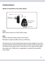
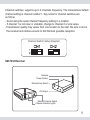
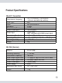
Converts Wired Camera to Wireless
(900 MHz)
Model: SM-401
2
(normally 1 year)
Copyright 2009 by SecurityMan v2.0
3
Notice:
900MHz wireless camera works at ISM band. It may cause interferences with
other wireless equipment that operates at the same band. Please turn off one
of the equipment to eliminate the interference.
Product Assurance
900MHz wireless camera will emit electromagnetic wave, just like other wireless products. But the output power of the products is lesser than other wireless products such as mobile phones. The 900MHz wireless camera meets
wireless frequency security standards and recommend indexes while working. These standards and indexes are certificated by academic organization
and represent the cogitative research of the scientific workers who continuously explore and annotate the involved fields. So we believe that our products are safe for customers.
Operating Restrictions
DO NOT use this product to violate one's privacy. Monitoring one's private
activities without consent is illegal and this product is not designed and
manufactured for these purposes.
DO NOT put this product near any medical equipment. Radio waves might
potentially cause breakdown of electrical medical equipment. This product
should be placed at least 1 feet away from any heart pacemaker. Radio
waves might potentially influence heart pacemaker and lead to respiratory
disturbance.
DO NOT use this product for any illegal activities. SecurityMan shall not be
responsible for any consequences of illegal conducts made by users.
4
Conditions
Please read the following messages to make sure whether your working
environment is suitable.
• Ensure there is enough space around the receiver for ventilation.
• The temperature should be kept between –10˚C and 50˚C (14˚F to 122˚F).
The relative humidity should remain from 20% to 80%.
• Avoid putting the product in places where occur might change rapidly in
temperature or humidity
• Keep it dry, dustless and avoid exposure in it directly in sunlight
• Keep product away from heat sources such as electric heater
• Do not use the camera near aggressive chemicals
• Do not place product near any magnetic objects
Maintenance
• Do not shake or stricken the product.
• In order to avoid inflammation or electric shock, this converter kit should be
kept away from exposure to rain or moist, and it shall not be put in or near
bath-rooms, washing pools, washhouses, moist basements, or swimming
pools, unless it is well shielded.
• In use of sockets set on walls or extension wires, attention should be paid not
to exceed their load capabilities to avoid inflammation or electric shock.
• Do not disassemble the product casings, otherwise the internal precision parts
may get damaged, or personal injury caused.
• Switch off the power supply in thunder and lightning weather or when not in
use for long periods of time.
• Do not attempt to service the product yourself as opening or removing covers
may expose you to dangerous voltage or other hazards. Refer all servicing to
qualified service personnel.
5
Table of Contents
Introduction
7
Features
7
Package Contents
7
Hardware Basics
SM-401T (Transmitter)
SM-7034 (Receiver)
8
8
9
Installaion Diagram
Installation Procedure
10
11
Product Specifications
13
6
Introduction
Thank you for purchasing the wireless converter. The wireless converter is a
convenient wireless security camera kit for indoor surveillance used to converts
any wired cameras to wireless (900MHz). A perfect solution for existing wired
cameras ideally for homes and businesses. It consists of a wireless transmitter,
a wireless receiver, and all the necessary accessories to put it to work.
Note: Please read the manual entirely before use.
Features
1. Turn any 12 volt wired CCTV camera to a wireless camera (900MHz)
2. Avoid the hassle of running cables
3. No interference from crowded 2.4GHz/5.8GH devices including Wi-Fi
network device.
4. Wireless transmission up to 330ft clear line of sight (100ft indoor)
5. Built-in microphone (transmitter)
6. Two-channel receiver supports up to two wireless cameras
Package Contents
•
•
•
•
•
•
1 x Wireless transmitter (SM-401T)
1 x Wireless receiver (SM-7034)
1 x 8VDC power adapter (for receiver)
1 x Mini power cable
1 x AV RCA cable
1 x User Manual
7
Hardware Basics
SM-401T (Transmitter for the wired camera)
Antenna
BNC Socket
(To Camera)
Channel Switches
Microphone
Power Jacks
Front
BNC socket: Connect to a wired camera output.
Back
Antenna: Sends the wireless signal to the receiver.
Microphone: Captures audible sound up to 25ft away.
Power jacks (x2): Use the existing wired camera’s power adapter to one of the
two jacks and then use the mini power cable to connect from the second jack to
the camera’s power input socket. Power jacks can only support power supply
that outputs up to 12VDC max, not applicable for cameras that use 24VDC
power output.
8
Channel switches: supports up to 2 channels frequency. The manufacture default
channel setting is channel number 1. Key notes for channel switches are
as follow:
- Avoid using the same channel frequency setting in a location.
- If channel 1 is not clear or unstable, change to channel 2 or vice versa.
-Transmission quality may varies from one location to the next. Be sure to move
the receiver and camera around to find the best possible reception.
Channel Switch Setup Diagram
SM-7034 Receiver
Antenna
Power Socket
Manual/Loop Switch
AV Output
Manual Channel Switch
Channel Indicator Lights
9
Receiver manual & loop Switch
A) In manual mode use the Channel Switch button located in the front of the
receiver to toggle between channel#1 & channel#2
B) In loop mode the receiver will auto dwell by switching between channel#1
& channel#2. The auto dwell time is fixed and preset to 5 seconds intervals.
A) Manual Mode
B) Loop Mode
Installation Diagram
CAMERA
DC POWER
TRANSMITTER
TV/VCR/DVR
RECEIVER
AV CABLE
DC POWER
10
Installation Procedures
1. Connect the SM-401T transmitter to a wired camera using the BNC connection.
2. Connect the mini power cable from the power socket of SM-401T transmitter
to the wired camera power input socket as shown below.
3. Plug the power adapter of the wired camera to the power outlet and connect
the power jack to the power socket of the transmitter (SM-401T).
11
4. Connect the power adapter to the power outlet and the power jack to the
receiver power input, the receiver will automatically turn on.
5. Connect the receiver to a monitor, TV, LCD, DVR (digital video recorder),
or VCR using the AV cable. (Yellow for video; red for audio).
6. Power on the monitor/TV/LCD and select input mode or auxiliary channel
(ie. VIDEO1, VIDEO2, LINE1, LINE2, etc.). If the A/V cable is connected to
a recorder; turn the recorder on and ensure the recorder is connected to an
output monitor.
Notes:
1. Avoid using with other 900MHz wireless devices (like cordless phone) at the same location
due to possible interferences.
2. If picture is not clear, try to change to another available channel. Or, move both the
transmitter/receiver around for better reception.
3. No more than two wireless transmitter converter at a location.
4. Many receivers can be used at a location for multiple rooms monitoring.
12
Product Specifications
SM-401T (Transmitter)
Transmission Frequency
Video Input
Audio
Bandwidth
Transmission Power
Power Consumption
Power Input
Dimensions (W x D x H)
Operating Temperature
Operating Humidity
Weight
FM, CH1=906MHz, CH2=924MHz
(channel selectable dip switches)
BNC
Microphone Built-in
18 MHz
2 mW
100 mA (Max.)
12VDC Max.
(NOT compliant with 24VDC power input)
1.38” x 1.29” x 1.54”
- 10 ~ +50 (Degree C)/+14 ~ +122 (Degree F)
<
_ 85% RH
25g
SM-7034 (Receiver)
Antenna
50 ohm SMA
Receiving Sensitivity
Intermediate Frequency
Video Output Signal Level
Audio Output Signal Level
Power Consumption
Power Supply
<
_ -85 dBm
480 MHz
+ 0.2 Vpp @75 ohm, S/N > 38dB
1.1 Vpp _
+ 1Vpp @ 600 ohm
3.0 Vpp _
165mA (Max.)
8VDC
Dimensions (W x D x H)
3.1” x 3.6” x 0.8”
Weight
174g
13