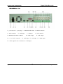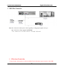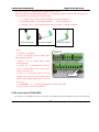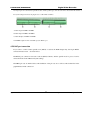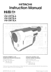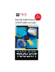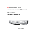
1
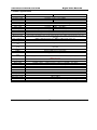
Mace Security Products, Inc. Presents:
Digital Video Recorder based on Mpeg4 Technology
Thanks for purchasing products of Mace Security International, Inc.
For your convenience in calling for service or technical support, please
record the following important information:
Model: DVR0404RW, DVR0804RW, DVR1604RW (select one)
Hard Disk: 80G, or __________
Serial #:
Date Purchased:
Sales Person:
Company Name:
Phone:
Fax:
Consult Mace’s website at http://www.mace.com for a complete line of
surveillance and security products.
2
General Safety Precautions
This manual applies to Mace DVR0404RW (4-Channel CD-R Writer) and DVR0804RW (8-Channel
CD-R Writer). DVR0804RW has been used as the example in all illustrations.
1.
Installation Environment
2.
Open Product Box and Verify Contents
3.
Before Power-up
3
1. Installation Environment
-
An UPS (Uninterrupted Power Supply) with power surge protection is strongly
recommended for DVRs and all associated devices (routers, DSL modems, etc)
-
Avoid extreme heat
-
Avoid direct sunlight
-
Avoid excessive humidity
-
Maintain horizontal mounting
-
Avoid excessive vibrations
-
Do not stack other devices on top of the DVR
-
Operate in well ventilated place, do not block the cooling fan
2. Open Product Box and Verify Contents
Check for the following accessories:
-
One power cord
-
One hard disc Ribbon Cable
-
One operation manual
-
One CD for utility software (normally it is not needed).
-
One remote control unit
-
Two AAA batteries
3. Before Power-up
-
Make sure the orange tab is set to 110V at the back of the DVR power supply
-
Be sure the UPS power supply is properly connected
-
Be sure to plug power cord into a reliable 110 VAC power source
4
Table Of Contents
General Safety Precautions ················································································· 3
1. Installation Environment··········································································· 4
2. Open Product Box and Verify Contents···················································· 4
3. Before Power-up ······················································································· 4
Chapter 1: Product Specifications and Features ················································· 7
1. Product Specification ·············································································· 2
2. Product Features ······················································································· 3
3. Storage Matrix ························································································ 4
Chapter 2: Basic System Operations ································································· 13
1. Start/Stop the DVR ··············································································· 14
2. Recording································································································ 15
3. Alarm Input/Output················································································· 16
4. Pan-Tilt Control ······················································································ 16
5. Network Operation ················································································· 16
Chapter 3: Operations from Front Panel ··························································· 17
1. Front Panel Overview ············································································· 18
2. Detail Key Function················································································ 19
3. Enter/Leave the Operation Menu···························································· 21
4. Maneuver in the Operation Menu··························································· 22
5. Menu Overview ······················································································ 23
6. Operation Description············································································· 27
6.1 Recording Control············································································· 27
6.2 Playback···························································································· 27
6.3 Pan-Tilt and Zoom Camera Control·················································· 29
6.4 Menu Detail ······················································································ 30
5
Chapter 4: Operations over Network ································································ 37
1. Setting Up the Client End ······································································· 38
2. Login and Logout ··················································································· 38
3. Operation of the Right Click Menu Items··············································· 40
4. Record Search and Playback··································································· 43
5. System Configuration ············································································· 45
6. Assistant·································································································· 50
Chapter 5: System Connections ········································································ 57
1. DVR Rear View ······················································································ 58
2. RS232 Port Connection ·········································································· 59
3. 25 Pin Alarm Transfer Box ·······································································60
4. RS-485 Port Connection ········································································· 61
Chapter 6: Serial Connection ············································································ 64
1. System Setting ························································································ 65
2. Software Upgrade Through Serial Port··················································· 66
Appendix 1 Remote Control Unit ····································································· 67
Appendix 2 Frequently Asked Questions ·························································· 68
Appendix 3 Hard Disk Installation ··································································· 69
LIMITED WARRANTY·······················································································71
6
Chapter 1
Product Specifications And Features
1.
Product Specifications
Product Features
Storage Matrix
7
1. Product Specifications
Parameter
Processor
Operation system
Model
Video input
Video output
Audio input
Audio output
Video display
Video standard
System resource
Image resolution
Motion detection
Video compression
Audio compression
Image compression
rate
Video recording
speed
Image quality
CDRW
Pre-Installed Hard
Disk
Hard Disk Expansion
HDD space used
Alarm input
Alarm output
Alarm relay
Network connection
Pan-tilt control
Power
Power consumption
Working temperature
Working humidity
Barometric pressure
Size
Weight
4 Channel
8 Channel
AMD ELANSC520/133 embedded microprocessor
Real-time operation system - RTOS
DVR0404RW
DVR0804RW
4 Channel (NTSC/PAL) BNC 1.0VP- P 75
8 Channel (NTSC/PAL) BNC 1.0VP- P 75
1 Channel PAL/NTSC BNC 1.0VP- P 75 video signal
4 Channel 200-1000mv10K (BNC)
8 Channel 200-1000mv10K (BNC)
1 Channel 2000mv 1K (BNC)
1(Full Screen) & 4(Quad) window displays
1(Full Screen),4(Quad),9 (3x3) window displays
NTSC 525 line, 60f/s – PAL 625 line, 50f/s
Real-time recording, one channel playback and network operation simultaneous (Triplex)
Real-time monitor 704×576, playback 352×288, VGA output 720×576
Area setting: 396 detection areas on the screen; detection sense setting: 3 levels detection sense for
each area
MPEG-4 CBR (fixed frame rate); MPEG-4 VBR (variable frame rate)
Audio - ADPCM 28.8 Mb/hour G.729 - 3.6 Mb/hour Video - 40-460 Mb/hour
352×288CIF format - 176×144QCIF format - 704×576 4CIF format.
Real-time mode: NTSC 1f/s - 30f/s for each channel adjustable. PAL 1f/s - 25f/s for each channel
adjustable;
6 levels selectable
Built-in CDRW writer for data backup
A 80 Gigbyte Hard disk is preinstalled
Inside equipped 4 IDE ports, able to install 8 HDDs inside, With CDRW option, up-to 5 internal
HDDs supported
Audio - ADPCM 28.8Mb/hour G.729 - 3.6Mb/hour Video - 40-460Mb/hour
8 channel voltage alarm input – 5 to 15V DC necessary for the alarm input.
3 channels output, - output in open/close contact or controllable - 12V output 30VDC 1A, 125VAC 0.5A - relay output.
RJ45 10M/100M Ethernet connection
RS485
110VAC/220VAC
60W
75W
10C – 55C
10 - 90 Relative
86kpa - 106kpa
2U standard industrial case 441mm (Wide) x 430mm (Deep) x 89mm (High)
11KG in Box
8
Parameter
16 Channel
Processor
Operation system
AMD ELANSC520/133 embedded microprocessor
Real-time operation system RTOS
Video input
Video output
Audio input
Audio output
Video display
Video standard
System resource
Image resolution
Motion detection
Channel
BNC 1.0VP- P 75
BNC 1.0VP- P 75
video signal
Channel 200-3000mv10K (RCA)
Channel 2000mv 1K (RCA)
1 4 ,16 window display
NTSC 525 line, 60f/s PAL 625 line, 50f/s
16 chs real-time recording, one channel playback and network operation simultaneous
Real-time monitor 704 576, playback 352 288, VGA output 720 576
Area setting:
detection areas on the screen; detection sense setting: 3 levels detection sense for
each area
CBR (fixed frame rate);
VBR (variable frame rate)
Audio ADPCM 28.8Mbyte/hour
Video 40-460Mbyte/hour
352 288 CIF format
704 576 4CIF format
Video compression
Audio compression
Image compression
rate
Video
recording
speed
Image quality
Hard disk
Alarm input
Alarm output
Alarm relay
connection
Network connection
Pan-tilt control
Backup
Power
Power consumption
Working temperature
Working humidity
Barometric pressure
Channel
MPEG mode: PAL 1frame/10second-25f/s for each channel adjustable; NTSC 1frame/10second-30f/s
for each channel adjustable
6 levels selectable
Inside equipped 4 IDE ports, able to install 8 HDDs inside, expand with external HDD case for another
12 HDDs
16 channel voltage alarm input
5
15V D. C. Needed for the alarm input
6 channels output, output in open/close contact
24VDC 1A,220VAC 0.15A relay ouput
RJ45 10M/100M Ethernet connection
Alarm input and output port,
110VAC/220VAC
75W
10
55
10
90
86kpa 106kpa
9
2. Product Features
-
-
Real-time Monitor (Video Displays)
o
1 Video output port to Video Monitor and 1 VGA port for video output to PC Type Monitor.
o
Single window (Full Screen) /4 windows (Quad) /9 windows (3x3) monitor diplay.
Compression Method
o
Multiple video compression modes: MPEG4 fixed frame variable frame.
o
4, 8, 16-channel audio/video real-time compression, independent hardware compression for
each channel, stable synchronization of sound and image.
-
Storage
o
o
o
-
-
Internally can hold 8 IDE-compatible large capacity Harddisk(HDD)
Alternative HDD operations that will reduce the power consumption and heat emission.
Overwrite (FIFO) and Stop (HDD Full) modes for DVR HDD recording.
Back-up
o
Built-in CD-RW drive to back up records onto CD-R disks, upgradeable to DVR-RW drive.
o
USB port for external back up of records.
o
Download the files on DVR to local PC through network.
Play and Record
o
Supports multiplexed operation: live monitor, record, search for downloading, one channel
play-back, and remote transmission simultaneously.
o
Multiple recording mode: Manual – Timing – Alarm - Motion Detection. Note: Alarm
Recording and Motion Recording have Pre-Alarm function.
o
Playback: With PIP or Multi-Channel Real-Time Monitor. Playback also available using
Network Connection.
o
o
Fast search for reviewing manual recording and alarmed recording.
Multiple play-back modes: X2, X4 & X8 fast play, pause, 15F/S, 5F/S slow play and frame by
frame playback.
o
Displays Time/Date during playback.
10
-
-
-
Alarm relay
o
8 channel external alarm input, video lost alarm and motion detection alarm.
o
Multi channel relay switch alarm output activates alarm relay and on-site light control.
o
Circuit Protection for Alarm inputs and outputs.
Pan-tilt Control
o
Supports Camera Pan-Tilt-Zoom (PTZ) Functions using RS485 Communication Protocol.
o
Integrates multiple protocols to control various PTZ speed domes.
Communication connection port
o
DB-25- (25 pin) connection for alarm inputs and PTZ control.
o
RS232 port for the connection with keyboard for central control, or with the computer serial
port for system upgrades and diagnostics.
o
Standard Ethernet port for remote viewing and control.
o
Remote real-time monitor.
o
Pan-tilt-zoom control.
o
Record search and real-time playback. Note: playback quality dependent on network conditions.
Downloading records through network.
o
System programming, settings & modification and system software upgrades available online.
o
Remote alarm processing and system log review remotely.
o
Embedded TCP/IP protocol and RTOS (Real Time Operating System) supports Web server
direct connection to operate and control all the above functions.
o
Administration mode: Three USER levels for logging in remotely.
password protected.
11
Each user login is
3. Storage Matrix
The HDD Capacities and Recording lengths are determined by capacity of the installed HDDs and the selected
image level.
The following storage time is based on the average use for HDD space for single channel recording.
Coding
CBR
Image level
Resolution
Frames
Average
Maximum data flux
space
HDD
/hour
1
30
128Kb/S
40MB
2
30
256Kb/S
80MB
3
30
384Kb/S
120MB
4
30
512Kb/S
160MB
5
30
768Kb/S
240MB
6
30
1Mb/S
320MB
Note: Adjustable frame rates, from 1fs to 30f/s can be selected. User can choose based on own needs.
Using other than 30f/s (Real time), HDD (Hard Disk) space can be greatly increased.
Following are storage calculation guidelines (in the number of Days):
Img
Quality
80G
MP4(CBR)
30F/S
1-ch
4-ch
8-ch
1(128kb/s)
128kb/s
61
15*
8
2(256kb/s)
256kb/s
30
8
4
3(384kb/s)
384kb/s
20
5
3
4(512kb/s)
512kb/s
15
4
2
5(768kb/s)
768kb/s
10
3
1
6(1024kb/s)
1024kb/s
8
2
1
* This reads that with a 80G harddisk, at CBR (constant bit rate) and Image Quality 1, DVR will be able to
record 15 days for 4 camera inputs.
12
Img Quality
80G
MP4(VBR)
MP4(VBR)
80G
MP4(VBR)
1-ch
4-ch
8-ch
1F/S
1-ch
4-ch
8-ch
1
116kb/s
67
17
9
12.5kb/s
621
155
78
2
160kb/s
49
12
6
25kb/s
312
78
39
3
212kb/s
37
9
5
44kb/s
176
44
22
4
330kb/s
24
6
3
50kb/s
156
39
20
5
447kb/s
17
4
2
62kb/s
124
31
16
6
825kb/s
9
2
1
88kb/s
88
22
11
Img Quality
80G
30F/S
2F/S
1-ch
4-ch
8-ch
3F/S
1-ch
4-ch
8-ch
1
25kb/s
311
78
39
44kb/s
176
44
22
2
44kb/s
176
44
22
45kb/s
172
43
21
3
50kb/s
156
39
20
55kb/s
140
35
18
4
63kb/s
124
31
15
84kb/s
92
23
11
5
78kb/s
100
25
12
100kb/s
76
19
10
6
92kb/s
84
21
10
122kb/s
64
16
8
Img Quality
10F/S
1-ch
4-ch
8-ch
12F/S
1-ch
4-ch
8-ch
1
71kb/s
108
27
14
80kb/s
96
24
12
2
109kb/s
72
18
9
130kb/s
60
15
7
3
133kb/s
60
15
7
149kb/s
52
13
6
4
175kb/s
44
11
6
210kb/s
36
9
5
5
258kb/s
32
8
4
275kb/s
28
7
4
6
443kb/s
16
4
2
525kb/s
16
4
2
13
Chapter 2 Basic System Operations
1. Start/Stop the DVR
Recording
Alarm Input/Output
Pan-tilt Control
Network
14
1. Start/close the recorder
Start the recorder
Plug in the power line; switch on the power button at the back of the recorder; power indicator light on; DVR
on; default single window for the video output displays; press Enter the Log-in screen appears on Monitor; If
the starting time is within the programmed recording time, the system will start recording function automatically.
Channel indicator lights will indicate the cameras in record mode. The system will work in a normal manner.
Note: if the system stops during HDD Boot detection, the HDD may not be installed right and please check the
HDD connections (Ribbon and Power Connections). *Please unplug the 120VAC power supply during HDD
installation*
1.2 Enter the setting menu
Before you enter the menu, you must input the password. There are two levels of password—User password and
Administrator password.
Administrator password
General user password
If input the user password, you have to input again at the next login; you are also not allowed to enter
system setting and admin setting.
Note: For the consideration of security, please change the Administrator password in admin settings.
Refer to Chapter 4 Front Panel Menu Operation for details.
1.3 Turning off the DVR
Press the POWER key on the front panel for 4 seconds to stop the current operations. Then switch off the power
button at the DVR rear to turn off the power.
1.4 Power off recovery
When the power is cut off abnormally, the recorder will recall it’s last state and continue where it left off. The
state indicator light is the same as it was before the power off.
15
2. Recording
The default recording mode after startup of the DVR is 24 hr continuous recording for each channel. The
User can program customized recording times for each camera. Instructions for the different recording modes are
as follows:
a) Timing Recording:
· Enter the menu, and set the timing period for the recording. See details at Menu>System setting>Timing
b) Manual Record Selection
· Press “Record” button on the remote controller or “Rec” on the front panel.
· Check the status of each channel in the recording menu; The Highlighted channels are in record mode.
· To select the channel to be recorded, press the related number key. Selected camera # will highlight on
your screen. When all cameras that need to be recorded are selected, press Enter to begin the recording.
· Repeat above steps and remove the highlight to stop the camera from recording. ·Press Cancel or ESC to
return without changes.
c) Alarm recording
· Connect the alarm input according to the device connection and the instructions.
·Program the related settings in the menu to start Alarm recording.
See details at Menu>System
setting>Alarm setting
d) Motion detection recording
· Record the channel only in need of motion detection. First confirm whether this channel is programmed in
Timing Recording; if it is, please turn off Timing Recording for the selected Camera..
· Program the related settings in the menu to start Motion detection recording.
Menu>System setting>Motion detection.
3. Alarm connection operation
16
See details at
· Connect the alarm input according to the device connection and the instructions.
· Connect the related alarm output relay on the DVR to associated alarm device. Example: lights, beeper, etc.
· Program the associated information in the menu. See details at Menu>System setting>Alarm setting
4. Pan-tilt control operation
· Confirm the proper connection of the pan-tilt-zoom and Communication Protocol. Set the Camera address.
· Confirm the proper wiring connection between the PTZ and RS-485 A & B lines and DVR’s 25-pin port’s A
& B lines.
· Set up the programming. See details at Menu>System setting>Control
· Select full screen call-up of associated P/T/Z Camera.
· Press and hold “Assistant” on the remote controller or “Fn1” on the front panel to select
· Use direction arrow keys to move and control the selections on the screen
5. Network connection operation
· Confirm correct network connections between DVR and computer
· Set the IP address, subnet mask and gateway of the computer and DVR separately. If there is no router in the
network, only the IP address is needed. If there are routers in the network, please enter the related gateway
and subnet mask.
· Ping ***.***.***.***
the IP address of the DVR to check the link of the network. A successful reply shall
look like (TTL value less than 64 ms is normal):
Reply from 68.153.205.130: bytes=32 time=31ms TTL=57
· Open IE browser and input the IP address of the DVR you want to log in to.
· For Network operation see details at Chapter 4
17
Chapter 3 Operations From Front Panel
1. Front Panel Overview
Detail Key Function
Entering the Operation Menu
Maneuver in the Operation Menu
Menu Overview
6. Operation Description
6.1 Recording
6.2 Playback
6.3 Pan-Tilt and Zoom Camera Control
6.4 Menu Detail
18
1. Front Panel Description
1.
Power Switch
2.
Camera Selection #
3.
Recording Light
4.
Control Cover
5.
CD-RW
6.
Onscreen Addr Entry
7.
Left Direction
8.
IR Remote Receiver
9.
ESC (Cancel)
10.
Enter
11.
Down Direction
12.
Up Direction
13.
Right Direction
14.
Information
15.
Single & PIP Selection
16.
FN2 (Function 2)
17.
Multi-screen Selection
18.
FN1 (Function 1)
19.
FN Indication Light
20.
Standby Light
21.
Jog Shuttle
22.
Multi-screen Selection
23.
Rec (Recording Control)
24.
ESC (Cancel)
25.
Replay Last Selection
26.
Slow Play
27.
Play/Pause
28.
Fast Forward
29.
Jump to Next Section
30.
Enter
Note: Outside Ring of the jog shuttle when turning clockwise is equal to right direction arrow, turning
counterclockwise is equal to left direction arrow; inner circle turning clockwise equal to down direction,
otherwise equal to up direction.
19
2. Keys functions
Order
1
2
Key name
Power switch and
indication light
Camera Selection
Numbers
3
Recording light
Logo
Function
Power switch - Power off by pressing the key 4 seconds.
POWER
Indication light
Manual Password # input, window shift or number input; 10
1, 2, 3 etc.
is used for numeric input 0.
LED (Red) on
If the LED light is RED, it means the recording is on
numbers
4
Plastic Cover
Black plastic
Dust-proof Cover
5
CD-RW
CD-RW
Used to Back-up records
6
Address
ADD
Input remote control address for the operation of DVR.
7 & 13
L & R On screen Cursor Control; shifting level 1 and level 2
Left & Right Arrows
menu; Left and Right Camera Pan control.
11 & 12
Up and Down Onscreen Cursor Control; change setup;
Up & Down Arrows
change number; Camera Tilt control.
8
9 & 24
IR Remote receiver
Used to receive the remote signal.
Cancels cursor selection.
Cancel
ESC
10
Enter
ENTER
14
Information
INFO
15
Single window display
During playback, restore to real-time monitor.
Enter Cursor Selection.
Enter main menu.
Press to show the system information.
Shift the window to single window
In the Full Screen Mode:
Press the key to display the menu of the Camera PTZ.
16
Function assistant 1
Fn1
When setting Motion Detection fields, Fn1 Enables Cursor
field selection.
During playback, display the playback status bar
17
18
Function assistant 2
During playback work with number key to realize PIP for the
Fn2
playback and real-time monitor.
Multi-Screen Display
Select to change from Full screen to multi-window display.
20
19
Assistant indication
Indication light for when Function assistant keys are used.
light
20
Indicator light for
Light on when DVR is in stand by Mode.
standing by
21
Direction control: outer Ring for Left and Right direction,
Jog shuttle
inner Ring for up and down; When in playback, outer circle
can control reverse, and multi-speed play.
22
Multi-Screen Display
Select for Multi-Screen; During playback, shift between
MULT
Playback and Real time display.
REC
23
Record
Start/stop recording, use with arrow keys
25
Play last section
Play the previous recording file.
26
Slow play
3 levels of slow play speed adjustments: (15f/S - 5f/S &
frame by frame)
Play/stop
27
Play/stop
/
28
Fast play
3 levels of fast play speed - X2 - X4 - X8.
29
Play next section
Play the next recording file after the current file.
30
Enter
When in real time mode, press to enter record search menu
Enter
ENTER
Enter the main menu.
21
3. Enter/Leave the Operation Menu
Press Enter key twice, the system will prompt for password.
Default Administrator password is “888888”.
Default User password is “666666”.
If not touched for 5 minutes, the system will automatically logout the currently user.
For security reason, the Administrator may choose to manually logout under Menu/ Logout
General
searching
Listing
Precise
Alarm
M
E
N
U
System INFO
General
Timing setting
System
File
HDD
Version
Image setting
Alarm setting
Pan-tilt setting
Motion
detection
Serial port
Advanced
option
Backup
File backup
Backup listing
Data backup
Logout
Backup
22
Password
File
Output
Read default
4.
Maneuver in the Menu System
Operation
Button-pressing
step
order
1 Confirm Enter
level 1
submenu
Enter level
2 submenu
Set menu
contents
Screen display
During real-time monitor, press to open the
password prompt, type in the correct password,
Enter main
menu and
Instruction
then the menu will auto open.
2 Direction arrows
Use arrows to select Icon Choice.
3 Confirm Enter
Press Enter to select choice
4 Direction
Use arrows again to select #2 submenu choice
5 Confirm Enter
Press Enter to select level 2 submenu
1 Use
Select the option to be revised, flashing item is
Direction
Arrow
the selection.
2 Direction
Use Up/Dn arrows to revise the settings.
3 Press Enter
Save is flashing, choose to confirm whether you
want to keep the revised setting and press Enter
again.
Direction
Exit the
current
menu
Arrow
Cancel ESC
Return to the last option of the current menu
Exit to the last level menu
You can set the multiple channels before you exit the current menu and save all the settings together.
23
Menu
Overview
Main menu
Menu level 1
RECORD
SEARCH
LIST
ALARM
Menu level 2
CH
1
DATE
24-10-2003
TIME
2:20 PM
PLAY
START
CH
1
DATE
24-10-2003
TIME
2:20 PM
LIST
SEARCH
CH
1
DATE
Remarks
Use DIRECTION arrows to perform settings
in menu level 2
See details
Use DIRECTION arrows to perform setting
in menu level 2.
See details
Records associated with Alarm Inputs.
24-10-2003
SEARCH
Not
able to search motion detection records.
START
See details
HDD NUM 0 2
FILE INFO
HDD CAP 0 1 6 0 0 8 6M
FREE SPACE 0 0 0 0 0 0 0 M
FILE START 2003-04-12 01 30AM
FILE END
HARD DISK
STATE
2003-05-13
09:00PM
INDEX
MASTER
SLAVE
INFORMATION
USB STATE NO
VERSION
Information cannot be modified
BIOS VERSION 2.45
ISSUE DATE 03 01 2003
WEB VERSION 1.23
BPS
CH.1
CH.2
0538Kb
0302 Kb
CH.3
CH.4
0267 Kb
0112 Kb
256M/H 132M/H
117 M/H
49M/H
CH.5
CH.7
CH.8
CH.6
0663 Kb
0227 Kb
291M/H
99M/H
0050 Kb
21M/H
0283 Kb
124M/H
24
!
Main menu
Menu level 1
GENERAL
SYSTEM
SETTING
SCHEDULE
IMAGE
ALARM
Menu level 2
DATE
10-28-2003
FORMAT MM-DD-YYYY
TIME
12:22:01
FORMAT AM/PM SAVETIME
INTERVAL 005 SEC
HDDFULL OVERWRITE
RECORDLEN 15 MIN
REMOTEADDR 108
COMMCTRL NONE
SAVE
CANCEL
CH
1
WEEK
SMTWTFS
SLOT1
00:00 – 24:00
STATE
ON
SLOT2
00:00 – 24:00
STATE
ON
SAVE
CANCEL
CH
1
MODE
CBR
AV
FRAMERATE
REAL
BITRATE
1024K
VIDEO LOSS
OFF
COVERED
OFF
VIDEO SET DEFAULT
TITLE
01 ON
CYCLE
OFF
SAVE CANCEL
CH
1
TYPE
NORAML CLOSE
RECORD CH
1234
ALMOUT
1234
DELAY
1SEC
SLOT1
00:00 – 24:00 ON
SLOT2
00:00 – 24:00 OFF
ALMSVR IP 192.168.000.118 OFF
SAVE
CANCEL
25
Remarks
See details at 6.4.3
See details at 6.4.3
See details at 6.4.3
See details at 6.4.3
!
Main menu
Menu level 1
PANTILT
CONTROL
SYSTEM
NETWORK
SETTING
MOTION
DETECTION
PASSWORD
FILE
Menu level 2
CH
1
PROTOCOL NONE
BAUDRATE 4800
ADDRESS
000
SAVE
CANCEL
See details at 6.4.3
IP
192.168.001.108
SUBNETMASK
255.255.255.000
GATEWAY
192.168.001.001
WEB PORT
00080
TCP PORT
37777
MONITOR
TCP
PLAYBACK
TCP
SAVE
CANCEL
CH
1
DELAY
30 SEC
ALMOUT OFF
LEVEL
MID
AREA
SET
TIME1
00:00 – 24-00 OFF
TIME2
00:00 – 24:00 OFF
SAVE
CANCEL
GUEST * * * * * *
CONFIRM * * * * * *
MANAGE * * * * * *
CONFIRM * * * * * *
SAVE CANCEL
PASSWORD ---------
ADMIN
OTHERS
DEFAULT
See details at 6.4.3
See details at 6.4.3
Only the Administrator password logged in is
able to change password.
See details at 6.4.4
See details at 6.4.4
DELETE
SETTING
Remarks
ALARM TIP
ON
SHUTDOWN PWD
OFF
OUTPUT X/Y POINT
000/000
PLAYBACK HEIGHT 480
AUDIO MODE PCM 8KHZ
TITLE COLOR
WHITE
MONITOR OSD
ON
MAINTENACE WEEK S M T W T F S
MAINTENACE TIME
12:00 AM
SAVE
CANCEL
LOAD DEFAULT CONFIGURATION?
YES
NO
26
Able to set the color of words on the menu.
Able to set the starting point of the monitor
screen and the size of the monitor screen,
playback screen.
See details at 6.4.4
!
Main menu
Menu level 1
BACKUP RECORDS
BACKUP
Menu level 2
DEVICE
HDD
CH
1
BACKUP SPEED NORMAL
STARTING DATE
See details at
6.4.5
2003-3-18
STARTING TIME
DELETE BACKUP
Remarks
12:18PM
ENDING DATE
2003-3-18
ENDING TIME
5:18PM
BACKUP
ADD
START
DEVICE
HDD
DELETE
CONFIRM
LOGOUT
27
!
6.Menu Operation Description
6.1 Recording Operation
Model
Button-pressing order
REC
1. Record
Instruction
Diplay
Press to enter screen display.
RECORD 1 2
3
5 6 7
2. Direction
or
the related number key
8
Press to toggle the recording state on/off. The
highlighted Camera # means Record On or selected to
Record..
3 Direction
4
RECORD 1 2
Arrow to change camera channels. The highlighted item
3
5 6 7
4
8
means On.
4 Record
REC
Press to save the setting.
OR Enter
6.2 Playback operation
Button-pressing order
Instruction
Display
Press the button to enter screen display.(if logged out, log
back in with password)
2 Play/Pause
Press twice to begin the playback (The on screen video
displays channel, date, time). If display shows no record
found, the operation will not take effect. After the
completion of the playback, display shows “The End”.
To display Record Information during playback, press Fn to display or hide the playback state bar.
28
!
6.2.1 Playback fast play
Button-pressing order
1 Fast play
Instruction
Display
During playback press this key to shift between 2X speed,
CH1 PLAY X2
4X speed, or 8X speed.
2 Play/Pause
During fast play press this key to shift between play and
pause.
3 Play next section, play last
section
Operates in playback state. Press
to view the next or
last record of the same channel.
6.2.2 Playback slow play
Button-pressing order
1 Slow play
Instruction
Display
During playback press to shift among 30f/s, 15f/s, 1f/s
speed.
2 Play/Pause
During slow play of the playback record press to shift
between play and pause.
3 Play next section, play last
Works when in Playback Mode. Press
section
next or last record of the same channel.
to view the
1f/s speed during slow play is a frame by frame selection.
29
!
6.3 Control of Pan-Tilt and Zoom Cameras
*The PTZ Camera # must be selected on DVR before you can control the camera from
the DVR or remotely.
Button-pressing order
Instruction
1 Refer to menu operation at
In Control setting select the related Channel and Protocol,
6.4.4
see the right picture. Set the Baudrate and Address of the
PTZ Camera. Press Enter to save.
2 Assistant function Fn1
When in Full Screen Mode, press Fn1 to enter the screen
display.
Press continuously to shift among PT CONTROL
PT CONTROL
DIRECTION
DIRECTION LENS CONTROL ZOOM FOCUS IRIS
LIGHT CONTROL(OFF ON). Use arrows to adjust.
3
Direction
Control the related pan-tilt, lens and light. Use Arrows to
select.
LIGHT CONTROL
OFF ON
30
!
6.4 Menu Operation Detail
*The following Menu settings must be saved before the changes take effect.*
6.4.1 Record search
The menu for record search is pictured at the right.
First set the channel#, then date and time you want to
search, then select START, the playback begins.
CH
List
First set the channel #,
1
date and time you want to search,
then select SEARCH, the screen shows the 8 recording files
following the searching time. Use
to select the file to be
CH 1
played. Press ENTER to begin the playback.
Note the letters before the record are equal to following
R—Record
Alarm
M—Motion Detection
A—Alarm
First set the search date, then select START, all the alarm records will
be displayed. Press
to select the record. Press ENTER to play
the alarm record. Note: motion detection alarm can not be searched in
DATE 2002-12-08
this category, but can be
searched in RECORD and LIST.
31
!
6.4.2 Informtion
File Info
Menu of Information is pictured at right.
Recording start time(the earliest recording time among all the HDDs)
and recording end time. The information cannot be changed.
HDD NUM 0 2
HDD CAP 0 1 6 0 0 8 6M
FREE SPACE 0 0 0 0 0 0 0 M
FILE START 2003-04-12 19 00 22
FILE END
HDD State
Display HDD index and the conditions of master drive and slave drive.
Note: The HDD being used,
Version
2003-05-13 17 00 44
will show as “W”.
The issuing date and ID of the operating system. The information cannot
be modified.
Real time display the frame rate of the current channels and the space
occupied
CH.1
CH.2
CH.3
CH.4
0538Kb
0302 Kb 0267 Kb 0112 Kb
Frame rates are in Kb/s
256M/H 132M/H 117 M/H 49M/H
HDD space occupied in MB/h
CH.5
0663 Kb
CH.6
CH.7
0227 Kb 0050 Kb
CH.8
0283 Kb
291M/H 99M/H 21M/H 124M/H
32
!
6.4.3 System Setting
Picture of the System Setting Menu
See screen shot at right:
General
DATE and TIME are used to modify the current system date and time;
after the modification reserve the change by selecting SAVETIME; in
HDDFULL if selecting OVERWRITE system covers the previous
recording files; RECORDLEN can set the length of each recording
DATE
10-28-2003
FORMAT
MM-DD-YYYY
TIME
12:22:01
file(15 mins, 30 mins, 60 mins)Note: 15 minutes is suggested.
FORMAT
AM/PM SAVETIME
COMMCTRL can Activate the communication control protocols. The
INTERVAL 005 SEC
HDDFULL OVERWRITE
existing comm control protocols are:
RECORDLEN 15 MIN
MODEM - Dial-up connection through modem.
AB-
matrix control
DH
Keyboard control
NONE
REMOTEADDR
108
COMMCTRL NONE
SAVE CANCEL
upgrading system through serial port
Note: System time shall NOT be changed freely; otherwise it
would cause the malfunction of recording search.
Schedule
Select the corresponding channel in CH. In WEEK the letter of each
day is chosen, when the letter displays are highlighted. SLOT1 and SLOT2
express the timed recording period of the current channel. SLOT2 should
be after the ending time of SLOT1. The setting range is 00:00-24:00
STATE ON means the time setting is on.
OFF means the time setting is
OFF.
Note: 1: If you need to record all day long, set SLOT1 as 00:00-24:00
& state is on; set SLOT2 as off.
2: When setting time in WEEK,
several days can be set at the same time.
When Reviewing a certain channel’s timing, only the current day will
be highlighted.
33
!
Image
In CH option select the related channel. In MODE there are CBR
(audio/video) and VBR (audio/video). AV is audio and video
synchronization, Video is the mode without audio (when there is no audio input
1
MODE
CBR
FRAMERATE
AV
REAL
use this way to save HDD space).When in CBR, Framerate is Real time, Bitrate
BITRATE
is the related maximum data flux.
VIDEO LOSS
OFF
COVERED
OFF
Use direction key to select the different
bitrates. When in VBR, Framerate 1f/s-25f/s are selectable. Video Loss on
means that alarm will be on when the video is lost, and also trigger the relay
device.
Alarm
CH
1024K
VIDEO SET DEFAULT
TITLE
CYCLE
01 ON
OFF
SAVE CANCEL
Select the relevant Camera in CH (this recorder has 8-Ch alarm input).
TYPE has NO (normal open) NC (normal close) output modes. If the
Camera number in RECORD is selected, recording would be started for that
Camera automatically when there is alarm input. If the alarm output port is
chosen, it will trigger the corresponding relay when there is an alarm input.
DELAY means to extend
clears.10, 20, 30
the recording time after receiving alarm signal
90SEC delays. When the outside alarm is cleared, the
system will extend the recording time automatically before closing alarm and
relay output. When Time 1 or Time 2 are on, if an alarm occurs within the time
of these settings, the recording will be triggered by alarm signals. The beginning
time should be earlier than the ending time.
The setting in Time 2 should be
later than the setting in Time 1. ALMSVR IP is used to transmit the alarm signals
to the designated IP server.
Pan-tilt control
Select the corresponding channel in CH, and choose the protocol
of the brand
name of the corresponding pan-tilt decoder in
PROTOCOL. ADDR is the address of the corresponding PTZ Camera.
34
!
IP is set by using
Network
or input the exact numbers to change
the IP address. IP address setting can only be here. The related
SUBNETMASK and GATEWAY should be set according to the IP
address. MONITOR and PLAYBACK can be changed by using
TCP/IP or MULTICAST. Save the setting in SAVE, and restart the
recorder.
Note:
MULTICAST: The users with Admin levels can monitor each channel
freely.
All other users can only view after Admin
releases camera. 5 users at maximum.
TCP Protocol: All users are able to monitor any channel. User shall
select Camera # desired. If the transmission is over
Internet, TCP should be chosen. 2 users can log in at a
maximum.
Motion detection
Select the Camera channel in CH. Open or close (On/Off)
the function in STATE. Choose how long you want to
continue the recording (10, 20, 30, ……90SEC) when motion is detected
and then cleared. ALMOUT controls the alarming state for motion
detection. SENS has three levels: LOW, MID, HIGH. AREA can be
accessed by pressing ENTER. The setting area can be divided in 192
sections. Red section means the current cursor position, and the blue
section is the motion detection area. Areas with no color are no motion
CH
1
DELAY
30 SEC
ALMOUT
SENS
OFF
MID
AREA
SET
SLOT1
SLOT2
08:00AM – 08-00PM ON
08:00AM – 08-00PM OFF
SAVE
CAMCE;
detection areas. Press Fn to locate the current section, then move the
cursor to cover the MD area needed; press Fn again to choose the MD
area. Press
to get the setting and press ENTER to confirm.
35
!
6.4.4 Admin setting
Password
Menu of Admin setting is pictured at Right:
Select GUEST and MANAGE. Press
or the number
key to change the password, then confirm the change by
inputting the password again. Press ESC to go back to the sub
menu. Only ADMIN level user can change the password.
File delete
Used to clear the data in the HDD. Be careful with this item.
Before you delete the data, you have to input the manage password.
SAVE
CANCEL
DATA DEL
PASSWORD: _______
During Alarm tip on, when there is alarm input from outside,
Others
the alarm information window will pop up. If Shutdown pwd is on,
you need to input the right manage level password before turning
off the DVR; if it is off, 4 seconds after pressing on the power
OFF
OUTPUT X/Y POINT
000/000
PLAYBACK HEIGHT
point are set for the starting point of the window on the screen,
AUDIO MODE
PCM
TITLE COLOR
WHITE
MONITOR OSD
ON
480
8KHZ
playback. The user can set the starting point of the monitor
MAINTENACE WEEK S M T W T F S
screen and the size of the monitor screen and the playback
MAINTENACE TIME
screen.
Press
ON
button the DVR will turn off. Output x o point and Output y
and Playback height is to set the window height during
Default
ALARM TIP
SHUTDOWN PWD
SAVE
12:00 AM
CANCEL
to get the setting and press ENTER to confirm. After the
default setting is selected, system will restore the original Factory
Default settings.
36
LOAD DEFAULT CONFIGURES?
YES
NO
!
6.4.5 Backup
Menu of Backup is Pictured at Right:
Backup records
Move the cursor to select the backup device, channel
number, backup speed, starting data and time, ending date and
time, and then select to start the backup, and system will display
the backup processing. If the user does not connect the backup
device correctly, the system will display: No backup disk; if the
device is full, it will display: Disk is full. During the backup, it
will display the time. For the backup device you can choose
among HDD/USB/CDR. If HDD is chosen as the device, the
backup speed can be selected between Fast and Normal. If the
backup speed is Fast, system will stop the current recording.
Delete backup
Select the backup device you want to delete the records from
first, and then confirm the deletion by selecting
DELETE
BACKUP
DEVICE HDD
DELETE CONFIRM
6.4.5 LOGOUT
Press ENTER
to logout .
To enter the menu again , password
is needed.
37
!
Chapter 5
Operation Over Network
There are two ways to access the DVR over the network: Using Microsoft Internet
Explorer(IE) or Mace Remote Client Software.
Using IE, no special software needs to be installed on the PC. A web control unit will be
downloaded to the computer automatically the very first time a connection to DVR is
initiated.
The Mace Remote Client Software needs to be installed properly to use the second
option. But the graphical user interface menu items are identical. Goto
http://www.mace.com/, under Support, download the Remote Client software.
1. Setting up the Client End
2. Login and Logout
3. Operation of the Right Click Menu Items
4.
Record Search
5.
System Configuration
6.
Assistant
38
!
1. Setting up the client end
No special software is needed to install on the DVR, PC or other devices in order to access DVR using the IE
browser.
If the IE responds back “Page Cannot Be Displayed” or “Server not Found”, check your network
connection carefully.
2. Login and logout
Please input the IP address of the DVR in the address column of the browser. Take the DVR’s IP address:
192.168.0.168 as an example: Input http://192.168.0.168. Note: The first time you visit this DVR the system
will pop up the dialogue box to ask whether you accept ActiveX or not, and please choose Yes, then the
system will install the software automatically.
On the remote monitor display, there is a monitor video window, with selection choices:
config(system setting)
login
logout
search,
Assistant(assistant setting) and so on.
39
!
Login Please select login, and the following dialogue box will pop up.
Input the username and password. There are three types of Users: Administrator, User, and Guest. For
detailed information please refer to User manage
in Assistant setting. The default username is admin, & password
is admin. For Security purposes, please change the administrator password.
If after the input of the username and password, the following box pops up(6-3). The system is indicating that some other
user has used this name and is logged in. Please use another name to log in.
If after the input of the username and password, the following box pops up. The system is indicating that the name or
Password input is incorrect, and to please try again.
40
!
Log out: If the logged in user needs to log out, please click logout button. The popup dialogue box appears. Please
choose Yes. See 6.5.
3. Operation of the Right Click Menu Items
After you log in as Administrator, the buttons like login, logout, search, config & Assistant are activated. Click the right
mouse key and the following interface Display:
41
!
If the DVR is 8 Channel, the real-time monitor will show 8 channel options; if 4 channel, it will show 4 channel options.
The right key menu includes: Real time monitor, Playback control bar, Pan-tilt control, Set volume, Net data flux,
Full screen, Resize video and so on.
Real time monitor
Among the displayed channels,(6-7)you may select the channel you want to see.
Playback control bar Please refer to Records playback.
Pan-tilt control
The Arrows Control the moving direction of the pan-tilt and the zoom, iris & focus of the lens.
See 6.8. Press the related buttons to control. Note: Before the PTZ will operate you must set the correct protocol of
the pan-tilt on the DVR configuration menu.
42
!
Set volume Audio volume is User selectable.. User can drag the bar to adjust or select Mute to cancel the sound.
Net data flux Display the statistics of the network transmission data flux. When there is no network data
transmission the statistics shows zero.
Full screen There are two ways to view full screen monitor: One is to double click the window directly; the other
is to select Full screen among the right click menu items. During multi-window state, choose one of the windows
and double click it for full screen display.
43
!
4. Records Search and Playback
Click on search, then fill in the required info on the pop up dialogue box for the records search.
6-11
Input recording time, channel number and searching type: Record or Alarm search, and the results will display
in the dialogue box. It displays 15 records from search time and forward.
Click Pageup and Pagedown to
select the desired records. Double click the desired record, and system will play the selected record, which
can be played at full screen. At the same time you can also perform a record download, and the record will be
automatically be saved at C:\Download.
Save record
stop save
capture picture
full screen
During the playback, you can operate the buttons in the playback bar such as: save record, stop save, capture
picture, fast play, pause, full screen. During the playback on the video screen, the video can indicate the
channel number, time and data flux of the record.
44
!
Download See 6-12, select the desired record and click Download.
6-12
The software supports the downloading of several records simultaneously. The default format of the
downloaded records’ name is:
file name, Channel # ,
date,
time,
extension name is .mp4(Example:
a-0120021205071028.mp4, 01 means channel 1, 20021205 means December 5th of 2002, 071028 means 7
o’clock 10 minutes 28 seconds).
6-13
45
!
To Save a File located in the Search Record Display, Select File, press the Download button. A Save Window
opens. Input the file name and choose Save. The screen shows the processing of the downloading until the
completion.
6-14
5.
System Configuration
Click Config button and a pop up the dialogue box appears. There are General
Timing
Image
Alarm
Motion Detection tabs of the five menu configuration screens.
Note: The grayed part of the menus that cannot be changed, can only be modified directly at the DVR.
General: Include the recording length setting. In Control Column select the channel number and its PTZ
decoder’s protocol, as well as the related address for the control of the PTZ Camera.
46
!
Timing 6-16 Allows the User to select the different channels and dates to perform the manual recording and 2
different periods of time. The set time in Time 1 and Time 2 are independent with the set time in Motion
detection. There is no week setting for Motion detection.
Timing of motion detection: User can set two time periods of the motion detection, time and the state of the
motion detection so as to activate the recording during the time period. Only when Motion Detection is On,
the set time period
takes effect. If the state of the two time periods are both Off, the system will not record
in motion detection.
6-16
47
!
Image With this menu, adjustments can be made for image quality and protocols of each channel.
Style: Among the options of the coding styles there are: VBR(variable baud rate), CBR(consistent baud rate),
f/10s, f/5s, f/2s, 1f/s, 2f/s, 3f/s, 4f/s, 5f/s, 6f/s, 8f/s, 10f/s, 12f/s, 15f/s & 20f/s. Select one of the styles and
save. For VBR and selectable frames there are 1, 2, 3, 4, 5 & 6 level of image quality. Please choose the
desired level.
Level 1:data flux 128Kb/S, Level 2: 256Kb/S, Level 3: 384Kb/S, Level 4: 512Kb/S, Level 5: 768 Kb/S, Level
6: 1Mb/S.
The different data flux demands on the related bandwidth and the transmission image quality is also different.
Among them, Level 6 demands on the highest bandwidth and has the best image quality.
48
!
Net transmission Protocol- There are TCP and Multicast (two types). Multicast protocol: the 1st user logged
in can control power, can view the image at will and other users can only follow this user to view the image. 5
users are allowed to view at the same time. TCP protocol: each user can view the image at will. According to
the need, users can choose between different protocols. If viewing is through the Internet you must choose
TCP. Up-to 5 users are allowed to view at the same time.
Alarm When there are alarm input signals, the user can select the recording channel and the output port for
the actual need.
6-20
49
!
Motion detection When the user sets the time period for Motion Detection, the motion detection will take
effect. The blue area is the selectable motion detection area. The User can move the dialogue box to choose
the correct area and can also set the sensitivity of the area due to the need. Click Full screen or press right
key on the area to display the motion detection area in full screen mode. After setting the area the user can
Save channel or Clear the area. The Alarm output field allows you to activate an output relay. The default
port is 2. If you want to set this channel fully as motion detection recording, you have to turn off the timing
recording of this channel.
6-21
50
!
6. Assistant
Assistant
Click on Assistant setting, as following, there are User manage - Record control - Apply for
control right - Log information - System information - Channel name - Upgrade BIOS, etc.
6-22
User manage: displays the user(Log-In) information of the DVR. The buttons to the right can let an admistrator
user save, add, modify, delete and cancel the information.
Three levels of users types: Administrator
fully set the system, modify & Use the system.; User
can
not set system parameters or modify other users’ information. This User can select and Operate existing
programming; Guest
can not set system parameter and records search, can only modify personal
information.
51
!
Add
Click Add to show the following dialogue box
The Admin User can add user information in this dialogue box, select your power. Note: There is only one
administrator allowed.
Modify
Select this button to show the following. User can modify the filled-in information.
52
!
Record control
Manually control the recording of each channel.
6-26
Apply for control power
Web client software can supply the login of multiple users. If you want to have the
control, you can click this option and confirm to have the control. (6-27). If a new user wants to have the
control, the new user has to apply and gain the authorization of the existing user with control . If the logged-in
users are all normal users, the first logged-in user gains the control power automatically. If a higher lever user
logs in later, they can gain the control power automatically. If only one user logs in or the logged-in user is
the user with control, the box is gray.
53
!
The picture below (6-28) is the other user sending request to the existing user with control.
Log information
The operations on the system are all recorded in log information.
54
!
System information
Check the basic information of the system. When sound is not needed, you can turn
off the audio. Due to the bandwidth considerations, the user can select the different Video transport modes,
Video type PAL or NTSC has to be selected correctly, 110vac, 60hz is normally NTSC, 220vac, 50hz is
normally PAL. If Auto recycle monitoring is on, system will sequence between all the channels
automatically with a user selectable dwell time. Net data flux
during real-time monitor will display the
statistics of the network data flux.
55
!
Channel name Cameras can be be named for each channel. No more than 12 Characters. The revised channel
names will be displayed on the screen. The default setting of the channel name is Channel No.1 thru Channel
No.8.
Upgrade BIOS
Administrator can upgrade the BIOS program remotely. A Browse window will pop up for
File Information. Open the related BIOS or Web file example: DVR0800.BIN or Multi-webfile.bin, and click
on Send. After the upgrading, system will automatically reboot to take on the new system software.
6-32
56
!
About
Version information – This palette displays information about the DVR and may be vital when
contacting MACE Support.
57
!
Chapter 6
System Connections
DVR Rear View
RS232 Port Connection
25 PIN Alarm Transfer Box
RS-485 Port Connection
58
!
1.
DVR Rear View
1-
Alarm – RS485 (DB-25)
2-
Audio Out (BNC)
3-
Audio In (BNC)
4-
Power Switch
5-
Power Plug-in
6-
RS232 (DB-9)
7-
VGA out (HD-15)
8-
USB port
9-
RJ45 (10 Base-T)
10- Video Out (BNC)
11- Video In (BNC)
Network connection note: When connecting directly to the network card of a computer, please use CAT-5
Crossover Cable; when connecting to a LAN or Router use CAT-5e cable.
59
!
1
power switch
5
VGA connection
9
NET network connection
12
16
2
power plug
6
3
220V/110V shift switch 4
Audio input
connection
RJ45
13
7
10
USB port
Audio output
Vedio input
Alarm output & control connection 17
14
RS232 connection
8
1394 connection
11
Vedio input
Vedio output
15
Alarm output
Alarm input
60
!
2. RS232 Port Connection
Note: The connection for DVR system software upgrading or debugging through the serial port
The connection for dial-up login through MODEM
3
25 Pin Alarm Transfer Box
Connect 25 pins of the transfer box directly with the 25 pins alarm input output connection of the DVR
61
!
Fasten the transfer box on the back panel of DVR with two screws
Pull out 6 connection terminals of the transfer box, corresponding connection marks can be clearly noticed.
Connect function line according to connection marks
Loosen the screws on the connection terminal; connection diagram
Insert lines needed to corresponding terminals
connection diagram
Fasten the screws on the terminals after insertion of the lines.(connection diagram
connection diagram
connection diagram
connection diagram
Notes:
terminal
a) “Ground” ground line
b)“+12v” provide the power to alarm device
with current less than 2A
c)“OUT 1 2” is two alarm outputs switch.
Nomal open type
d) 485 A B is communication connection,
used to connect such recorder control device
such as control decoder
e) +12 C ” is control power output, is used for
standby power for smoke sensor alarm device..
dismiss of the alarm needs the device to turn off
the power.
f) ALARMIN 1…8 is alarm input. High level voltage input. Input
voltage is 6-24V 12V is recommended
screw
10-Pin connection for DVR1604RW
If you want to control pan-tilt, lens and process the relay of the alarming signals by the DVR, the 10-pin port can realize. The
62
!
four 10-pin port can control various pan-tilt decoders, and the specific type of the decoder can be selected from the Control of
the System setting in the menu. On plug the foot’s serial number is marked.
A: Alarm input: ALARM1~ALARM8
B: Alarm input: ALARM9~ALARM16
C: Alarm OUTput: ALARM1~ALARM5
D:ALARM6 output and 12V controllable pressure AB line port
4. RS-485 port connection
If you want to control Camera pan-tilt-zoom (P/T/Z) or activate the DVR Output relay, the 25-pin RS485
connection must be used.
See detail below.
The RS485 port connection can control various (P/T/Z) Cameras, and the specific model or protocol can be
selected from the Control Menu in System settings.
The DB25 pin outs are marked below. The definition of the pin outs are as follows: The broken line in the
graph indicates inside connection
63
!
Alarm input ALARM 1
Alarm output
ALARM 8
ALARMOUT1
ALARMOUT2
Controllable +12V output
120
Combined as RS485 B line
+12V output
(EOL)
Combined as RS485 A line
A
B
Decoder
Gnd
A
End of Line
resister
required.
B
Decoder
a)
Pins 1,14,2,15,3,16,4,17 connects to alarm input: ALARM1~ALARM8
b)
Pins 5 & 18 = OUTPUT Relay 1
c)
Pins 7&20 = OUTPUT 3 is a controllable +12V output.
d)
Pins 8, 9 & 21 are +12V power output, Use for Low current items only such as Relays and Alarm Devices.
e)
Pins 10 & 22 are the B line of RS485, Pins 11 & 23 are the A line of RS485;
f)
Pins 12, 13, 24 & 25 are Ground (Gnd).
- 6 & 19 = OUTPUT Relay 2 Each Relay (normally open):
64
!
- Connection of the alarm input:
Pwr Supply, Alarm Device and DVR connection
Alarm Device
+12V
GND
Com
NC
ALARMIN
Typical
Instruction of the alarm
connection to
DVR alarm in.
GND
input end:
8
channel
alarm
inputs with NO or
NC alarm(normally
open or normally
close type). The power out of the alarm sensor can be provided by the DVR(Low current only) or (External
alarm power supply)
·Instructions for alarm device power from DVR:
N/O or NC alarm outputs refer to information below..
·Instruction of the controllable +12V
Available for Low Current Power to Alarm devices.
·Instruction of RS485 A & B line:
Used to connect the A and B line of the PTZ units.
65
!
·Module sketch of the alarm input end
·Module sketch of the alarm output end
Relays’ parameter of the alarm output end
Model: G6H
Relay Material
Silver
Rating, resistance &
Rated switch capacity
30VDC 1A, 125VAC 0.5A
load.
Maximum switch power
62.5VA 33W
Maximum switch voltage
125VAC, 110VDC
Maximum switch Current
1A
Pins with same polarity
750VAC 1minute 50/60Hz
pins with different polarity
1000VAC 1minute 50/60Hz
between relay and loop
1000VAC 1minute 50/60Hz
between relays with same polarity
1500V (10 160us)
Insulation
Surge voltage
Length of open time
3ms max
Length of close time
3ms max
Longevity
Temperature
Mechanical
100 106
(10Hz)
Electric
200 103
(0.5Hz)
-40~+70
66
!
Chapter 6
Serial Port Operations
System Setting
Software Upgrade
67
!
1
System Setting of the Terminal
The system’s operation can also be controlled through the RS232 port. The specific operation is as follows: First, copy
“Terminal” and new DVR system software to the computer. Connect the computer with the DVR via the RS232 port. Run
“Terminal” program and create the connection between the computer and the DVR.
The settings information for the connection is: Baud rate— 115200bps
Data bit— 8 bits
Stop bit— 1 stop
Check — no parity
Control on data flow— no
You can log in by username admin (default user with administrator ) for the serial port login.
Login steps:
Press any key to enter the login interface which displays the following:
Username: admin
Input the name; press the “enter” key. Then, input the password as follows:
Password: admin
If the username and password are correct, the system will allow entry via the serial port. The detailed
functions are the same as the menu setting.
68
!
2. Serial port upgrading operation
After connecting with the above operations, please continue with the below operation:
Press any key to enter login interface as following:
Username - admin
Enter username and press Enter. Enter the password as follows:
Password - dahua
System enters into DEBUG state, and input BIOS.
Click
Communication
in
the
menu
Press Enter.
Field——Send
file,
and
open
upgrading
program
file
(DVR0804_NTSC.BIN—8 Channel DVR BIOS program, please complete this operation within 20 seconds,
otherwise a Time out occurs). System begins to upgrade automatically and after the upgrading is completed, a
system reboot will occur.
69
!
Appendix 1
Remote Control Unit
Remote controller – Operates like On-Screen Buttons
1. Address
2. Multi Screen
3. Camera Select
4. Record
5. Function Key
6. Enter/Menu
7. ESC (Cancel)
8. Direction Arrows
9. Jump to Next
10. Previous Selection
11. Jump Backward
12. Stop
13. Next Selection
14. Reverse
15. Play/Pause
16. Fast Forward
70
!
Appendix 2
1.
Frequently Asked Questions
After Power up, “No HDD” message is flashing on the local monitor
This is an indication that either the harddisks are not installed correctly or no harddisk is installed at all. Refer to
Appendix 2 Hard disk installation. Also inside the DVR there is a yellow sticker with instructions on harddisk
installation.
2.
When I power down the DVR, why do I have to press and hold the power button for 4 seconds?
First of all, using the front orange power button to shut down the DVR will make sure the DVR properly finish and
close all it operation and file system, thus eliminate many possible causes for harddisk errors leading to data loss.
This is the correct way of powering down a DVR.
Secondly, requiring holding the button for over 4 seconds is to avoid accidental shutdown of the DVR due to
unintended touch of the button. You can make the shutdown more secure (i.e. avoid unauthorized shutting down)
by
activating
the
shutdown
password
protection
feature.
(MENU->ADMIN
SETTING->OTHERS->SHUTDOWN PASSWORD)
3.
What does the sound of the buzzer mean when normally starting the machine
When the machine is started successfully, it will tone out a short ring.
When the HD can not be identified, it would tone out a longer ring.
When communication with the controller panel is abnormal, it sends out a tone of one long ring and two short in
series.
4.
Can I control the recording time?
The recording time unit is per day. Besides timing recording, there are other recording methods such as motion
detection recording, manual recording, external event triggering recording. Confirm that each of the settings is
correct.
5.
The indicator light is flashing while recording
Check the external video input signal first. Such phenomena would happen when the input signal is not
standard. If it is not the input signal, it must be caused by that the reading speed of the HD is too slow. In this
situation, the current HD should be changed.
71
!
6.
Why the screen is black after I switch off and on the power?
The power supply comes with the DVR has a built-in protection mechanism. After the power is shut down, you
have to wait for at least 5 seconds before turn it on again. Turn off the power, wait for 5 seconds, and turn it on
again. If this does not correct the problem, contact your Mace technical support hotline.
7.
What kind of external equipment could be connected to the Recorder?
It can work together with various matrix units, multiplexers, switchers, quads and PTZ Domes.
72
!
Appendix 3
Hard Disk Installation
Hard disk installation
There is one 80G hard disk (HD) preinstalled in the Mace DVR, unless you ordered a special configuration. So
normally you DO NOT have to go through these steps. This procedure only applies to cases where there is no
built-in hard disk in the DVR or additional hard disks need to be installed.
In total, a maximum of 8 large capacity hard disks can be installed inside the machine if a CD burner is not
needed. With a CD burner, there can be a total of 5 internal large capacity hard disks. User can decide the
number of hard disks according to required image quality, recording time and recording length.
Installation steps
Dismantle the top cover,
open the cabinet
Dismantle the HD
Separate the up and
bracket
down part of the bracket
Combine the two parts of
Set the master-slave jumper wire
the bracket
(refer to the clue on the back of the
Install HD
Connect the HD bracket
HD)
73
!
Connect HD data line to
Plug in HD power line
Close the cover and install the screws
IDE port
74
!
LIMITED WARRANTY
Mace Security Products, Inc. (MACE) warrants to the original purchaser of this product that it shall be free of defects
resulting from workmanship or components fro a period of one (1) year from the date of sale. Defects covered by this
Limited Warranty shall be corrected wither by repair or, at MACE’s discretion by replacement. In the event of
replacement, the replacement unit will be warranted for the remainder of the original one (1) year period or thirty (30)
days, whichever is longer. THERE ARE NO OTHER ORAL OR WRITTEN WARRANTIES, EXPRESSED OR
IMPLIED, INCLUDING BUT NOT LIMITED TOTHOSE OF MERCHANTABILITY OR FINESS FOR A
PURTICULAR PURPOSE.
This Limited Warranty is nontransferable and does not apply if the product has been damaged by negligence, accident,
abuse, misuse, modification, or misapplication. To be eligible for warranty service, a defective product must be sent to
and received by MACE within twelve (12) months of the date of sale and be accompanied with proof of purchase. MACE
does not warrant that this product will meet your requirements; it is your sole responsibility to determine the suitability of
this product for your purposes. MACE does not warrant the compatibility of this product with your computer or related
peripherals software.
MACE’S SOLE OBLIGATION AND LIABILITY UNDER THIS WARRANTY IS LIMITED TO THE REPAIR OR
REPLACEMENT OF A DEFECTIVE PRODUCT. THE MNUFACTUREER SHALL NOT, IN ANY EVENT, BE
LIABLE TO THE PURCHASER OR ANY THIRD PARTY FOR ANY INCIDENTAL OR CONSEQUENTIAL
DAMAGES OR LIABILITY IN TORT RELATING TO THIS PRODUCT OR RESULTING FORM ITS USE OR
POSSESSION.
75
!