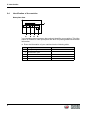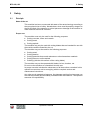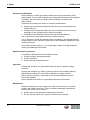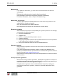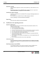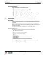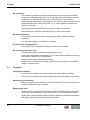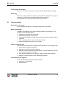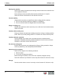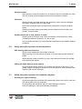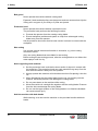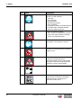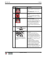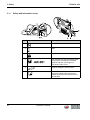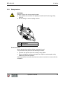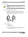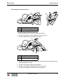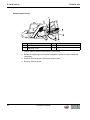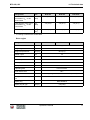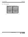
1
Operator's manual Gasoline cut-off saw BTS 630, 635, 635s 02.2011 0217780en / 004 Manufacturer Wacker Neuson SE Preußenstraße 41 80809 München www.wackerneuson.com Tel.: +49-(0)89-354 02-0 Fax: +49-(0)89-354 02-390 Translation of the original operator's manual in German Contents BTS 630, 635 1 Foreword .................................................................................................................... 5 2 Introduction ............................................................................................................... 6 2.1 Means of representation for this operator's manual ........................................... 6 2.2 Wacker Neuson representative .......................................................................... 7 2.3 Described machine types ................................................................................... 7 2.4 Identification of the machine............................................................................... 8 3 Safety ......................................................................................................................... 9 3.1 Principle.............................................................................................................. 9 3.2 Qualification of the operating personnel ........................................................... 12 3.3 Protective gear ................................................................................................. 13 3.4 Transport .......................................................................................................... 14 3.5 Operating safety ............................................................................................... 15 3.6 Safety during the operation of hand machines ................................................. 17 3.7 Safety during the operation of combustion engines ......................................... 17 3.8 Safety during cut-off saw operation .................................................................. 20 3.9 Maintenance ..................................................................................................... 24 3.10 Safety and information labels ........................................................................... 25 3.11 Safety and information icons ............................................................................ 28 3.12 Safety devices .................................................................................................. 29 4 Scope of delivery .................................................................................................... 30 5 Structure and function ........................................................................................... 31 5.1 Application ........................................................................................................ 31 5.2 Functionality ..................................................................................................... 31 6 Components and operator's controls ................................................................... 32 7 Transport ................................................................................................................. 35 8 Initial start up .......................................................................................................... 36 8.1 Mounting the cutting attachment on the outside............................................... 36 9 Use and operation .................................................................................................. 41 9.1 Prior to starting the machine............................................................................. 41 9.1.1 Checks before startup .......................................................................... 41 9.1.2 Changing the cutting blade................................................................... 41 9.2 Starting up ........................................................................................................ 43 9.2.1 Starting the engine ............................................................................... 43 9.3 Operating the machine ..................................................................................... 47 9.4 Decommissioning ............................................................................................. 48 Operator's manual 3 BTS 630, 635 10 Maintenance ............................................................................................................ 49 10.1 Maintaining the emission control system.......................................................... 49 10.2 Maintenance schedule ..................................................................................... 50 10.3 Maintenance work ............................................................................................ 51 10.3.1 Cleaning the machine........................................................................... 51 10.3.2 Topping up with fuel ............................................................................. 51 10.3.3 Tightening the V-belt ............................................................................ 53 10.3.4 Checking the thrust washers ................................................................ 54 10.3.5 Cleaning/Changing the air cleaner ....................................................... 55 10.3.6 Checking/cleaning/replacing the spark plug ......................................... 57 10.3.7 Replacing the V-belt ............................................................................. 59 10.3.8 Replacing the fuel filter ......................................................................... 62 10.3.9 Setting the idle speed ........................................................................... 63 10.3.10Cleaning the spark arrestor .................................................................. 64 10.3.11Cleaning the exhaust port .................................................................... 65 11 Troubleshooting ...................................................................................................... 67 12 Accessories ............................................................................................................. 68 13 Storage ..................................................................................................................... 69 14 Technical data ......................................................................................................... 70 14.1 BTS 630, 635, 635s.......................................................................................... 70 14.2 Fuel mixture table ............................................................................................. 72 15 Emission control warranty ..................................................................................... 73 EC Declaration of Conformity ................................................................................ 77 4 Operator's manual 1 Foreword 1 Foreword This operator's manual contains information and procedures for the safe operation and maintenance of your Wacker Neuson machine. In the interest of your own safety and to prevent accidents, you should carefully read through the safety information, familiarize yourself with it and observe it at all times. This operator's manual is not a manual for extensive maintenance and repair work. Such work should be carried out by Wacker Neuson service or authorized specialists. The safety of the operator was one of the most important aspects taken into consideration when this machine was designed. Nevertheless, improper use or incorrect maintenance can pose a risk. Please operate and maintain your Wacker Neuson machine in accordance with the instructions in this operator's manual. Your reward will be troublefree operation and a high degree of availability. Defective machine parts must be replaced immediately! Please contact your Wacker Neuson representative if you have any questions concerning operation or maintenance. All rights reserved, especially reproduction and distribution rights. Copyright 2011 Wacker Neuson SE No part of this publication may be reproduced in any form or by any means, electronic or mechanical, including photocopying, without the expressed written permission of Wacker Neuson. Any type of reproduction, distribution or storage on data media of any type and form not authorized by Wacker Neuson represents an infringement of copyright and will be prosecuted. We expressly reserve the right to make technical modifications – even without special notice – which aim at further improving our machines or their safety standards. 5 2 Introduction 2 2.1 Introduction Means of representation for this operator's manual Warning symbols This operator's manual contains safety information of the categories: DANGER, WARNING, CAUTION, NOTICE. They should be followed to prevent danger to life and limb of the operator or damage to equipment and exclude improper service. DANGER This warning notice indicates immediate hazards that result in serious injury or even death. f Danger can be avoided by the following the actions mentioned. WARNING This warning notice indicates possible hazards that can result in serious injury or even death. f Danger can be avoided by the following the actions mentioned. CAUTION This warning notice indicates possible hazards that can result in minor injury. f Danger can be avoided by the following the actions mentioned. NOTICE This warning notice indicates possible hazards that can result in material damage. f Danger can be avoided by the following the actions mentioned. Notes Note: Complementary information will be displayed here. 6 2 Introduction Instructions f This symbol indicates there is something for you to do. 1. Numbered instructions indicate that you have to carry out something in a defined sequence. 2.2 This symbol is used for lists. Wacker Neuson representative Depending on your country, your Wacker Neuson representative is your Wacker Neuson service, your Wacker Neuson affiliate or your Wacker Neuson dealer. You can find the addresses in the Internet at www.wackerneuson.com. The address of the manufacturer is located at the beginning of this operator's manual. 2.3 Described machine types This operator's manual is valid for different machine types from a product range. Therefore some figures can differ from the actual appearance of your machine. It is also possible that the descriptions include components which are not a part of your machine. Details for the described machine types can be found in the chapter Technical data. 7 2 Introduction 2.4 Identification of the machine Nameplate data The nameplate lists information that uniquely identifies your machine. This information is needed to order spare parts and when requesting additional technical information. f Enter the information of your machine into the following table: Item 8 Designation 1 Group and type 2 Construction year 3 Machine no. 4 Version no. 5 Item no. Your information BTS 630, 635 3 3.1 3 Safety Safety Principle State of the art This machine has been constructed with state-of-the-art technology according to the recognized rules of safety. Nevertheless, when used improperly, dangers to the life and limb of the operator or to third persons or damage to the machine or other materials cannot be excluded. Proper use The machine must only be used for the following purposes: Cutting concrete, stone and ceramic. Cutting metal. Cutting asphalt. The machine may only be used with cutting blades that are intended for use with the machine and the material to be cut. The machine may not be used for the following purposes: Cutting wood. Cutting plastics. Cutting materials that contain asbestos or other hazardous materials. Cutting fibrous or soft materials. Grinding (with the side surface of the cutting blade). The machine may not be operated with blades, knives, brushes, etc. Do not use the machine as a hand-held circular saw. Its proper use also includes the observance of all instructions contained in this operator's manual as well as complying with the required service and maintenance instructions. Any other use is regarded as improper. Any damage resulting from improper use will void the warranty and the liability on behalf of the manufacturer. The operator assumes full responsibility. Operator's manual 9 3 Safety BTS 630, 635 Structural modifications Never attempt to modify the machine without the written permission of the manufacturer. To do so will endanger your safety and the safety of other people! In addition, this will void the warranty and the liability on behalf of the manufacturer. Especially the following are cases of structural modifications: Opening the machine and the permanent removal of components from Wacker Neuson. Installing new components which are not from Wacker Neuson and not equivalent to the original parts in design and quality. Installation of accessories which are not from Wacker Neuson. It is no problem to install spare parts from Wacker Neuson. It is no problem to install accessories that are available in the Wacker Neuson product range of your machine. Please refer to the installation regulations in this operator's manual. Do not drill into the housing, e. g. to install signs. Water could penetrate the housing and damage the machine. Requirements for operation The ability to operate the machine safely requires: Proper transport, storage and setup. Careful operation. Careful service and maintenance. Operation Operate the machine only as intended and only when in proper working condition. Operate the machine in a safety-conscious manner with all safety devices attached and enabled. Do not modify or disable any safety devices. Before starting operation, check that all control and safety devices are functioning properly. Never operate the machine in a potentially explosive environment. Maintenance Regular maintenance work is required in order for the machine to operate properly and reliably over time. Failure to perform adequate maintenance reduces the safety of the machine. 10 Strictly observe the prescribed maintenance intervals. Do not use the machine if it requires maintenance or repairs. Operator's manual BTS 630, 635 3 Safety Malfunctions If you detect a malfunction, you must shut down and secure the machine immediately. Eliminate the malfunctions that impair safety immediately! Have damaged or defective components replaced immediately! For further information, refer to chapter Troubleshooting. Spare parts, accessories Use only spare parts from Wacker Neuson or such that are equivalent to the original parts in design and quality. Only use accessories from Wacker Neuson. Non-compliance will exempt the manufacturer from all liability. Exclusion of liability Wacker Neuson will refuse to accept liability for injuries to persons or for damage to materials in the following cases: Structural modifications. Improper use. Failure to comply with this operator's manual. Improper handling. Using of spare parts which are not from Wacker Neuson and not equivalent to the original parts in design and quality. Using of accessories which are not from Wacker Neuson. Operator's manual Always keep the operator's manual near the machine or near the worksite for quick reference. If you have misplaced the operator's manual or require an additional copy, contact your Wacker Neuson representative or download the operator's manual from the Internet (www.wackerneuson.com). Always hand over this operator's manual to other operators or to the future owner of the machine. Country-specific regulations Observe the country-specific regulations, standards and guidelines in reference to accident prevention and environmental safety, for example those pertaining to hazardous materials and wearing protective gear. Complement the operator's manual with additional instructions taking into account the operational, regulatory, national or generally applicable safety guidelines. Operator's manual 11 3 Safety BTS 630, 635 Operator's controls Always keep the operator's controls of the machine dry, clean and free of oil or grease. Operating elements such as ON/OFF switch, throttle levers etc. may not be locked, manipulated or changed without authorization. Checking for signs of damage Inspect the machine when it is switched off for any signs of damage at least once per work shift. Do not operate the machine if there is visible damage or defects. Have any damage or defects eliminated immediately. Supervision Never leave the machine running unattended! 3.2 Qualification of the operating personnel Operator qualifications Only trained personnel are permitted to start and operate the machine. The following rules also apply: You are at least 18 years of age. You are physically and mentally fit. You have received instruction on how to independently operate the machine. You have received instruction in the proper use of the machine. You are familiar with required safety devices. You are authorized to start machines and systems in accordance with the standards governing safety. Your company or the operator has assigned you to work independently with this machine. Do not operate the machine if you have a pacemaker. Incorrect operation Incorrect operation or misuse by untrained personnel can endanger the health and safety of the operator or third persons and also cause machine and material damage. Operating company responsibilities The operating company must make the operator's manual available to the operator and ensure that the operator has read and understood it. 12 Operator's manual BTS 630, 635 3 Safety Work recommendations Please observe the recommendations below: 3.3 Work only if you are in a good physical condition. Work attentively, particularly as you finish. Do not operate the machine when you are tired. Carry out all work calmly, circumspectly and carefully. Never operate the machine under the influence of alcohol, drugs or medication. This can impair your vision, reactions and your judgment. Work in a manner that does not endanger others. Ensure that no persons or animals are within the danger zone. Protective gear Work clothing Clothing should be appropriate, i.e. should be close-fitting but not restrict your movement. When on construction sites, do not wear long hair loosely, loose clothing or jewelry including rings. These objects can easily get caught or be drawn in by moving machine parts. Only wear clothing made of material that is not easily flammable. Personal protective gear Wear personal protective gear to avoid injuries or health hazards: Non-skid, hard-toed shoes. Work gloves made of durable material. Overalls made of durable material. Hard hat. Ear protection. Face protection. Eye protection. Breathing protection in the case of dusty ambient air. When cutting metal wear work clothing made of material that is not easily flammable. Danger of fire due to sparks. Operator's manual 13 3 Safety BTS 630, 635 Ear protection This machine generates noise that exceeds the country-specific permissible noise levels (individual rating level). It may therefore be necessary to wear ear protection. You can find the exact value in the chapter Technical Data. When wearing ear protection while working, you must pay attention and exercise caution because your hearing is limited, e.g. in case someone screams or a signal tone sounds. Wacker Neuson recommends that you always wear ear protection. Wear special ear protection which allows you to hear audio signals. Breathing protection If a lot of dust is produced when cutting, always wear suitable breathing protection. Use the water supply or an extractor if possible. Provision of fire extinguishers Ensure that a fire extinguisher is always to hand on the worksite. Do not exceed the service life The machine produces vibrations and generates noise. Observe the regulations which apply in your country and guidelines concerning the maximum service life of the machine. Always wear the prescribed safety clothing. Details on noise and vibration levels produced by the machine can be found in chapter Technical Data. 3.4 Transport Carrying the machine Do not carry or transport the machine when the cutting blade is rotating. Only carry the machine if the engine is idling and the cutting blade is not rotating. Switching off the machine Before you transport the machine, it must be switched off, and the engine must be given sufficient time to cool down. Emptying the tank Wacker Neuson recommends that the fuel tank be emptied and the carburetor run dry prior to transporting it. Fuel could run out, e.g. if the machine is tilted. Observe the national safety guidelines and the hazardous materials regulations that apply to the respective means of transportation. 14 Operator's manual BTS 630, 635 3 Safety Transporting the machine Secure the machine on the transport device against tilting, falling or slipping. Restarting Machines, machine parts, accessories or tools that were detached for transport purposes must be re-mounted and fastened before restarting. Only operate in accordance with the operating instructions. 3.5 Operating safety Explosible environment Never operate the machine in a potentially explosive environment. Work environment Familiarize yourself with your work environment before you start work. This includes e.g. the following items: Obstacles in the work and traffic area. Load-bearing capacity of the ground. The measures needed to cordon off the construction site from public traffic in particular. The measures needed to secure walls and ceilings. Options available in the event of an accident. Safety in the work area When working with the machine especially pay attention to the following points: Electric lines or pipes in work area. Gas lines or water lines in the work area. Material becoming separated, dropping down or ejected. Make sure that you do not put other persons in danger. Pay maximum attention in the vicinity of drops or slopes. Risk of falling. Maintain a sufficient distance from flammable materials. Checks before starting work Check the following points before beginning work: Condition of cutting blade. Safety devices. Operator's manual 15 3 Safety BTS 630, 635 Starting the machine Observe the safety information and warning notices located on the machine and in the operator's manual. Never attempt to start a machine that requires maintenance or repairs. Start the machine as described in the operator's manual. Vertical stability Always make sure that you stand firmly when working with the machine. Do not work with the machine on ladders or scaffolding. Do not use the machine at heights above shoulder height. Danger of falling over Operate the machine so that it cannot tip over or fall down from bordered areas, edges and steps. Caution with movable parts Keep your hands, feet and loose clothing away from moving or rotating machine parts. Parts of your body being pulled in or crushed can cause serious injuries. Caution with toxic materials Some materials may contain toxic chemicals which are released during demolition. Therefore personal protective equipment must be worn to prevent inhalation of and skin contact with work dust. No persons endangered Be sure that no persons are endangered by flying or falling materials. Always work very attentively, and anticipate potential hazards. Switching off the machine Switch off the engine in the following situations: Before breaks. If you are not using the machine. Before storing the machine, wait until it has completely stopped running. Store the machine or put it down in such a way that it cannot tilt, fall down or slip. Storage Set the machine down or store it securely so that it cannot tilt, fall down or slip. 16 Operator's manual BTS 630, 635 3 Safety Storage location After operation, allow the machine to cool and then store it in a sealed-off, clean and dry location protected against frost and inaccessible to children. Vibrations When manually operated machines are intensively used, long-term damage caused by vibrations cannot be precluded. Observe the relevant legal instructions and guidelines to minimize vibration stress. Details on vibration stress associated with the machine can be found in the chapter Technical Data. Health hazards due to dust particles or vapor Working with the machine may cause the release of dust particles or vapor containing hazardous materials, e.g. silicon dust. Only cut materials which you are familiar with and always wear suitable breathing protection. 3.6 Safety during the operation of hand machines Safe working with hand machines Secure loose workpieces with suitable methods. While working, as a rule hold the machine on the provided handles with both hands. While working, hold the machine in such a way that hand injuries are avoided when hitting hard objects. Setting the hand machine down properly Set the machine down carefully. Do not drop the machine to the floor or from greater heights. Dropping the machine can cause injuries to other persons or the machine itself can be damaged. 3.7 Safety during the operation of combustion engines Checking for signs of damage Check the engine while switched off for leaks and cracks in the fuel line, tank and fuel cap at least once per work shift. Do not operate the machine if there is visible damage or defects. Have any damage or defects eliminated immediately. Operator's manual 17 3 Safety BTS 630, 635 Dangers during operation Combustion engines can be dangerous, particularly during operation and when refueling. Read and follow all safety instructions. Otherwise there is a risk of personal injury and/or damage to property! Do not start the engine near spilt fuel or if you smell fuel – this may cause an explosion! Remove the machine from such areas. Remove the spilt fuel immediately! Do not change the engine speed Do not change the preset engine speed, as this may cause engine damage. You may only change the idle speed. The idle speed must be set such that the cutting blade does not rotate while the engine is idling. Preventing fires Open flames and smoking are strictly prohibited in the immediate vicinity of the machine. Make sure that waste, such as paper, dry leaves or grass do not accumulate around the exhaust muffler. The waste materials may ignite. Safety precautions when refueling Please observe the following safety-relevant instructions when refueling: 18 Do not refuel near open flames. Do not smoke. Turn off the engine before refueling and allow it to cool down. Refuel in a well-ventilated environment. Wear fuel-proof protective gloves and, if there is the possibility of spraying, protective goggles and clothing. Do not inhale fuel vapors. Avoid skin and eye contact with fuel. For refueling, use clean tools such as a hopper. Do not spill fuel, especially onto hot parts. Remove any spilt fuel immediately. Use the correct fuel grade. Do not mix fuel with other liquids. Fill the tank only up to the maximum marking. If there is no Maximum marking, do not fill up the tank completely. Lock the fuel cap securely after refueling. Operator's manual BTS 630, 635 3 Safety Operation in closed rooms In closed or partially closed rooms such as tunnels, drifts or deep trenches, ensure sufficient ventilation by, for example, providing a powerful exhaust air fan. Danger of poisoning! Do not inhale exhaust fumes. They contain toxic carbon monoxide that can lead to unconsciousness or death. Caution with hot parts Do not touch any hot parts such as the engine block or exhaust muffler during operation or directly afterwards. These parts can become very hot and cause severe burns. Cleaning the engine Clean the engine when it is cool to remove any dirt. Do not use gasoline or solvents. Danger of explosion! Health hazard due to exhaust fumes Warning The engine's exhaust fumes contain chemicals which are known to the State of California to cause cancer, congenital defects or other reproductive anomalies. Notes on the EPA engine (for USA and Canada) Caution This machine is equipped with an EPA certified engine. Operating the machine at an atmospheric pressure below 96 kPa may increase emissions and decrease fuel efficiency and performance. Do not use any starter sprays Highly flammable starter sprays pose a fire hazard. Do not use any starter sprays. Starter sprays are highly flammable and can cause backfiring and engine damage. Operator's manual 19 3 Safety 3.8 BTS 630, 635 Safety during cut-off saw operation Kickback If the upper quarter of the cutting blade is applied to a material, the machine can be flung back toward the operator with great force. The machine and the rotating cutting blade can cause severe injury. To prevent kickback, follow these rules: While working, as a rule hold the machine on the provided handles with both hands. Do not use the upper quarter of the cutting blade to cut. Make sure that the material does not shift out of place. Ensure that the cut does not become constricted during the cutting process. Ensure that the cutting blade does not become pinched during the cutting process. Pulling away When the cutting blade is set onto the material from above, the machine pulls away toward the front. While working, as a rule hold the machine on the provided handles with both hands. 20 Operator's manual BTS 630, 635 3 Safety Preventing pinching Prevent the cut from becoming constricted and pinching the cutting blade during the cutting process. Support the material such that the cut remains open and does not become constricted during the entire cutting process. Notes regarding cutting blades The cutting blade must be suitable for use with the cut-off saw. The cutting blade must be suitable for the material to be cut. The speed allowed for the cutting blade must be the same as or higher than the maximum machine spindle speed. Mount the cutting blade such that its rotation direction is the same as that of the machine. Only use cutting blades with permissible cutting blade diameters. When using cutting blades with a hole diameter greater than the machine shaft, use the suitable adapter ring. Only use undamaged cutting blades. Ensure that you also follow the instructions of the cutting blade manufacturer. Do not use cutting blades that have fallen. Change the cutting blade only when the engine has been turned off. Always tighten the cutting blade with the specified torque. Test the new cutting blade for approx. 1 min at maximum speed (without cutting). Do not use the side surface of the cutting blade for grinding. Only use cutting blades with use-by dates that have not expired. When storing cutting blades, always lay them flat in an area that is protected from frost. Only operate the machine with a mounted cutting blade If you operate the machine without a cutting blade, conical spring washer and screw could become loose, causing severe injury. Only operate the machine with mounted cutting blade. Operator's manual 21 3 Safety BTS 630, 635 Belt guard Never operate the machine without a belt guard! Exposed V-belts and belt pulleys are dangerous and can cause serious injuries if they pull in any part of your body or if parts are ejected. Protective hood Never operate the machine without a protective hood. The protective hood performs the following functions: Protects the operator from the rotating cutting blade. Diverts workpiece particles and sparks or chips from a damaged cutting blade away from the operator. Set the protective hood such that its lower section is almost in contact with the workpiece. Wet cutting Use a water sprayer when dust formation is excessive, e.g. when cutting concrete or stone. Only use cutting blades that are suitable for wet cutting. Before ending the wet cutting process, allow the cutting blade to run without the water sprayer until it is dry. Notes regarding work methods Set the protective hood such that its lower section is almost in contact with the workpiece. The protective hood can catch material flung away from the work area and divert it away from the operator. Always operate the machine at full throttle even when first placing it into the cut. When first placing the the cutting blade into the cut, set it slowly onto the material. Excessive pressure can damage the cutting blade. Do not press down on the machine while cutting. Move the machine in a straight line together with the cutting blade. Pressure from the side can damage the cutting blade. Do not use the upper quarter of the cutting blade to cut. Machine kickback can cause severe injury. Hold the machine with both hands While working, as a rule hold the machine on the provided handles with both hands. 22 Operator's manual BTS 630, 635 3 Safety Do not stand in the machine's swing area Hold and guide the machine such that no body parts are in the machine's swing area. Securing the material Before cutting, secure the material so that it does not slide away or tip over. Do not ever secure the material with your foot. Remove foreign objects before cutting Before cutting, remove foreign objects such as nails, etc. from the cutting area. Supporting the machine's weight At the end of the cutting procedure the cutting blade no longer supports the machine's weight. The operator must support the machine's weight. While working, as a rule hold the machine on the provided handles with both hands. Cutting several materials at once Do not cut several materials in one cutting procedure. Cutting very thin materials Make sure that very thin materials do not get trapped between the cutting blade and the lateral protection cover. Do not touch a rotating cutting blade Never touch a rotating cutting blade with your hand or any other body part. Danger of severe injury. Running cutting blade The cutting blade continues to run for awhile after the throttle lever is released. Danger of injury. Danger of fire due to sparks Danger of fire due to hot workpiece particles flung away from the work area. Do not work near flammable materials. Only wear clothing made of material that is not easily flammable. Do not leave any tools inserted Before operating the machine, make sure that tools have been removed. Operator's manual 23 3 Safety 3.9 BTS 630, 635 Maintenance Maintenance work Service and maintenance work must only be carried out to the extent described in these operating instructions. All other procedures must be performed by your Wacker Neuson representative. For further information, refer to chapter Maintenance. Switching off the engine Before carrying out care or maintenance work, switch off the engine and allow it to cool down. For gasoline powered engines, you must pull off the spark plug cap. Cleaning Always keep the machine clean and be sure to clean it each time you have finished using it. Do not use gasoline or solvents. Danger of explosion! Do not use high pressure washers. Permeating water can damage the machine. When electrical equipment is present, this can pose a serious injury risk from electric shocks. Assembling safety devices If it was necessary to dismantle safety devices, they must be reassembled and checked immediately after completing maintenance work. Always tighten loosened screw connections, complying with prescribed starting torque. Handling operating fluids safely Observe the following points when handling operating fluids, e.g. fuels, oils, greases, coolants etc.: 24 Always wear personal safety clothing. Avoid skin and eye contact with operating fluids. Do not inhale or swallow operating fluids. In particular, avoid contact with hot operating fluids. Burn and scalding hazard. Dispose of replaced or spilled operating fluids according to the applicable regulations for environmental protection. If operating fluids escape from the machine, cease operation of the machine and have it repaired immediately by your Wacker Neuson representative. Operator's manual BTS 630, 635 3.10 3 Safety Safety and information labels Your machine has adhesive labels containing the most important instructions and safety information. Make sure that all the labels are kept legible. Replace any missing or illegible labels. The item numbers for the labels are in the parts book. Item Label Description 1 2 Do not exceed the maximum cutting blade diameter. Only use cutting blades with the specified hole diameter. Do not exceed the maximum cutting blade width. The machine may not be operated with blades, knives, brushes, etc. Operator's manual 25 3 Safety BTS 630, 635 Item Label Description 2 Wear personal protective gear to avoid injuries or health hazards: Hard hat. Ear protection. Eye protection. Breathing protection. Face protection. Work gloves made of durable material. Overalls made of durable material. Non-skid, hard-toed shoes. 2 Danger of fire due to sparks. Do not work near flammable materials. Only wear clothing made of material that is not easily flammable. 2 Before operation, read and follow the information in the operator's manual. 2 Smoking and open flames are prohibited. Danger of fire. 2 Maximum spindle speed. Maximum peripheral speed. The speed allowed for the cutting blade must be the same as or higher than the maximum machine spindle speed. 26 2 Guaranteed sound power level. 2 The machine may only be operated with a fuel mixture consisting of unleaded gasoline and two-cycle engine oil. The mixture ratio is 50:1. Operator's manual BTS 630, 635 3 Safety Item Label Description 2 Danger of kickback. Machine kickback can cause severe injury. Do not use the upper quarter of the cutting blade to cut. 2 Cutting blades can break, causing severe injuries. Only use undamaged cutting blades. Do not use cracked, broken or twisted cutting blades. 2 Danger of poisoning. Do not inhale exhaust fumes. They contain toxic carbon monoxide that can lead to unconsciousness or death. In closed or partially closed rooms such as tunnels, drifts or deep trenches, ensure sufficient ventilation by, for example, providing a powerful exhaust air fan. 3 EU emission information label 3 EPA emission information label (for EPA machines). Emission Control (Exhaust & Evaporative) EPA 2010 and later. The emission control system for the engine is EM (Engine Modification) and for the fuel tank the control system is EVAP (Evaporative Emissions) or N (for Nylon tank). Product emission durability (Emission compliance period). The 300 hours emission durability compliance period is the time span selected by the manufacturer certifying the engine emissions output meets applicable emissions regulations, provided that approved maintenance procedures are followed as listed in the maintenance section of this manual. This label is an example only and may vary from machine to machine. Operator's manual 27 3 Safety 3.11 BTS 630, 635 Safety and information icons Item 28 Symbol Description 1 Choke. 2 Start. 3 Stop. 4 The machine may only be operated with a fuel mixture consisting of unleaded gasoline and two-cycle engine oil. The mixture ratio is 50:1. 5 Mark for setting the V-belt tension. 6 Machine's direction of rotation. Mount the cutting blade such that its rotation direction is the same as that of the machine. Operator's manual BTS 630, 635 3.12 3 Safety Safety devices WARNING Danger of injury due to open moving parts. f Only operate the machine with properly installed and functioning safety devices. f Do not modify or remove safety devices. Item 1 Designation Protective hood Protective hood Never operate the machine without a protective hood. The protective hood performs the following functions: Protects the operator from the rotating cutting blade. Diverts workpiece particles and sparks or chips from a damaged cutting blade away from the operator. Set the protective hood such that its lower section is almost in contact with the workpiece. Operator's manual 29 4 Scope of delivery 4 BTS 630, 635 Scope of delivery Item 30 Designation Item Designation 1 Machine 4 5 mm Allen wrench 2 Operator's manual 5 6 mm Allen wrench 3 Parts book 6 Combination wrench 13/19 mm Operator's manual BTS 630, 635 5 5.1 5 Structure and function Structure and function Application Use the machine only as intended, see chapter Safety, Proper use. 5.2 Functionality Principle The machine is a gasoline cut-off saw. It is driven by a two-cycle combustion engine. The powertrain from the engine to the cutting blade is driven by a centrifugal clutch and V-belt. The machine has an electronic ignition system that is maintenance-free. The multi-stage air cleaner system consists of a cyclone, foam material prefilter and paper air cleaner cartridge. Operator's manual 31 6 Components and operator's controls 6 32 BTS 630, 635 Components and operator's controls Item Designation Item 1 Front handle 8 Fuel tank 2 Water supply 9 Recoil starter 3 Multifunction switch 10 Cutting blade 4 Throttle lever lock 11 Protective hood 5 Rear handle 12 Decompression valve 6 Throttle lever 13 Fuel pump 7 Lock button Operator's manual Designation BTS 630, 635 6 Components and operator's controls Water supply You can connect a water supply unit to the water supply connection. The water supply performs the following functions: Cools the cutting blade evenly. Causes dust particles to stick together. Multifunction switch You can switch the machine on and off with the multifunction switch. The multifunction switch has a choke setting for cold starts. Throttle lever lock Unintentional pressing of the throttle lever is prevented by the throttle lever lock. You can only press the throttle lever if you are pressing the throttle lever lock at the same time. If you release the throttle lever, the throttle lever lock also returns to its original position. Throttle lever The machine speed can be continuously varied using the throttle lever. Lock button The lock button can lock the throttle lever in the half-gas position. Recoil starter The recoil starter starts the engine. Protective hood The protective hood performs the following functions: Protects the operator from the rotating cutting blade. Diverts workpiece particles and sparks or chips from a damaged cutting blade away from the operator. Set the protective hood for operation such that workpiece particles are diverted away from the operator. Decompression valve When starting the engine, the decompression valve allows some of the compressed air to escape from the cylinder. The lower compression in the cylinder reduces the drag on the starter rope. When the engine is running, the decompression valve returns to its original position. Operator's manual 33 6 Components and operator's controls BTS 630, 635 Fuel pump The fuel pump is used to fill the fuel lines and the carburetor after the machine has not been used for a while. The integrated return pipe prevents too much fuel from entering the carburetor as a result of excessive pumping. 34 Operator's manual BTS 630, 635 7 7 Transport Transport WARNING Improper handling can result in injury or serious material damage. f Read and follow all safety information of this operator's manual, see chapter Safety. WARNING Hazard of fire and explosions by fuel. Any fuel that escapes can ignite and cause severe burns. f Lift and move the machine in the upright position. Transporting the machine 1. Switch off the engine. 2. Detach the cutting blade. 3. Lift the machine using the front handle. 4. Place the machine on or into a suitable means of transport. 5. Secure the machine against falling over and down or sliding. Operator's manual 35 8 Initial start up 8 BTS 630, 635 Initial start up WARNING Improper handling can result in injury or serious material damage. f Read and follow all safety information of this operator's manual, see chapter Safety. 8.1 Mounting the cutting attachment on the outside By default the cutting attachment is mounted in the center of the machine. The cutting attachment can be mounted on the outside to maneuver around obstacles that are very close to the cutting line (e.g. curbs or brick walls). When the cutting attachment is in the external position, using the guide cart makes it even easier to see the cutting line. Performing preparations 1. Switch off the engine. 2. Let machine cool off. 3. Detach the cutting blade. Note: You must detach the cutting blade because otherwise, after the conversion, the rotation direction of the cutting blade will no longer be the same as that of the machine. 36 Operator's manual BTS 630, 635 8 Initial start up Converting the protective hood Item Designation 1 Hose connection (2 pieces) 2 Vibration dampers 1. Unscrew both hose connections and remove them. 2. Rotate the protective hood clockwise as far as it will go. 3. Unscrew and remove the vibration dampers. Item Designation 1 Adjustment handle 2 Vibration dampers 4. Rotate the protective hood counter-clockwise until the mounting hole in the vibration damper is visible. 5. Position the vibration damper and tighten it. 6. Unscrew the adjustment handle on top and remove it. 7. Position the adjustment handle below and tighten it. Operator's manual 37 8 Initial start up BTS 630, 635 Slackening the V-belt Item Designation Item 1 Screw (2 pieces) 3 2 Adjusting screw 4 Designation Belt guard 1. Loosen both of the belt guard screws a few turns. 2. Rotate the adjusting screw counter-clockwise until the V-belt is slackened completely. 3. Unscrew the belt guard screws and remove them. 4. Remove the belt guard. 38 Operator's manual BTS 630, 635 8 Initial start up Mounting the cutting attachment on the outside 1. Remove the cutting attachment. 2. Clean the cutting attachment, V-belt pulley, belt guard and screws. 3. Rotate the cutting attachment 180° and place it in position. 4. Place the V-belt in position. Item Designation Item Designation 1 Hose connection (2 pieces) 3 Adjusting screw 2 Belt guard 4 Screw (2 pieces) 5. Place the belt guard in position and affix it with screws. 6. Rotate the adjusting screw clockwise until the square nut is located between the two marks. 7. Tighten the belt guard screws. Torque 25 Nm. 8. Position the hose connections and tighten them. Operator's manual 39 8 Initial start up BTS 630, 635 9. Turn the thrust washer 2-3 times to make sure the tension is equal across the V-belt. 10. Check the V-belt tension again and re-tighten the V-belt if necessary. 40 Operator's manual BTS 630, 635 9 9 Use and operation Use and operation WARNING Improper handling can result in injury or serious material damage. f Read and follow all safety information of this operator's manual, see chapter Safety. 9.1 Prior to starting the machine 9.1.1 Checks before startup Checking the machine Always check the following points before beginning work: Damage to the machine and to all components. If the machine is damaged, do not start the machine. Have any damage or defects eliminated immediately. 9.1.2 Damage to the cutting blade (cracks, sections broken off, deformation, off balance, etc.) Fuel level, see chapter Maintenance. V-belt tension, see chapter Maintenance. Tightness of the protective hood. Changing the cutting blade Performing preparations 1. Place the machine upright on a flat surface. 2. Set the multifunction switch to Stop. Operator's manual 41 9 Use and operation BTS 630, 635 Changing the cutting blade Item Designation Item Designation 1 Bore 4 Thrust washer 2 Spindle 5 Screw 3 Cutting blade 1. To block the shaft, put an Allen wrench into the bore. Note: If necessary, rotate the spindle until the Allen wrench engages in the bore. 2. Unscrew and remove the screw together with the thrust washer. 3. Clean thrust washer and spindle of the machine. 4. Place the cutting blade onto the spindle in the correct rotation direction. 5. Place the screw together with the thrust washer in position and tighten. Torque 23 Nm. 6. Remove the Allen wrench from the bore. 7. Test the new cutting blade for approx. 1 min at maximum speed (without cutting). 42 Operator's manual BTS 630, 635 9 Use and operation 9.2 Starting up 9.2.1 Starting the engine Performing preparations Item Designation 1 Fuel pump 2 Decompression valve 1. Set down the machine such that the cutting blade can rotate freely. 2. Set the multifunction lever to the appropriate position. Cold engine: Position "choke". Warm engine: Position "I". 3. Press the fuel pump bellows repeatedly until the bellows is completely filled with fuel. 4. Actuate the decompression valve. If you detect resistance when pressing, move the decompression valve back and forth a bit. When the engine is running, the decompression valve returns to its original position. Operator's manual 43 9 Use and operation BTS 630, 635 Bringing the throttle lever into the start position Item Designation Item 1 Throttle lever lock 3 2 Throttle lever 4 Designation Lock button 1. Press and hold the throttle lever lock and the throttle lever. 2. Press the lock button. 3. Release the throttle lever. The throttle lever is locked in the half-gas position. 4. Release the lock button. 44 Operator's manual BTS 630, 635 9 Use and operation Starting the engine NOTICE Improper handling can damage the machine. f Do not pull the starter rope as far as it can go. f Let starter rope slowly roll back in. CAUTION Incorrect handling during starting can result in minor injuries. f Do not pull the starter rope until sufficient space is available and nobody is in the immediate vicinity. Note: When starting the engine, move to a position at least 3 m from the fueling area. Item Designation 1 Starter rope 2 Front handle Item Designation 3 Rear handle 1. Grasp the front handle with one hand. 2. Place your foot in the rear handle to stabilize the machine. 3. Pull out the starter rope slowly until compression resistance can be felt and then let it slowly roll back in again. Operator's manual 45 9 Use and operation BTS 630, 635 4. Pull the starter rope with force, but not suddenly. When you first hear the engine ignite, move the multifunction switch from the "Choke" position to the "I" position. If necessary, actuate the decompression valve once again. 5. Pull the starter rope with force, but not suddenly (several times, if necessary) until the engine starts. 6. Let starter rope slowly roll back in. 7. Press the throttle lever to release the lock in the half-gas position. 8. Allow the engine to warm up. 46 Operator's manual BTS 630, 635 9.3 9 Use and operation Operating the machine Note: When cutting, lightly pressing the cutting blade against the cutting material produces a very pleasant vibration response as well as a particularly narrow cut. Holding and guiding the machine WARNING Injuries from insufficiently guided or uncontrolled machine. f Always hold machine with both hands and stand firmly. 1. Stand in a fixed position. 2. Always hold the machine with both hands, using both handles. Setting the protective cover Item 1 Designation Adjustment handle f Use the adjustment handle to set the protective hood such that its lower section is almost in contact with the workpiece. Operator's manual 47 9 Use and operation 9.4 BTS 630, 635 Decommissioning Switching off the machine Item Designation 1 Multifunction switch 2 Throttle lever 1. Release the throttle lever. 2. Set down the machine in such a way that it cannot tilt, fall or slip. 3. Set the multifunction switch to "Stop". 4. Detach the cutting blade and store in a dry place. 48 Operator's manual BTS 630, 635 10 Maintenance 10 Maintenance WARNING Improper handling can result in injury or serious material damage. f Read and follow all safety information of this operator's manual, see chapter Safety. WARNING Hazard of poisoning by exhaust fumes. Exhaust fumes contain toxic carbon monoxide that can lead to unconsciousness or death. f Carry out maintenance work only when the engine is off. 10.1 Maintaining the emission control system Normal maintenance, replacement or repair of emission control devices and systems may be performed by any repair establishment or individual; however, warranty repairs must be performed by a dealer/service center authorized by Wacker Neuson. The use of service parts that are not equivalent in performance and durability to authorized parts may impair the effectiveness of the emission control system and may have a bearing on the outcome of a warranty claim. Operator's manual 49 10 Maintenance 10.2 BTS 630, 635 Maintenance schedule Task Daily before operation Check fuel system for: Fuel tank fill level. Leaks in fuel tank and fuel cap. Check V-belt tension. Tighten V-belt as necessary. Visual inspection of all parts for damage. Check function of throttle lever, throttle lever lock and lock button. Check protective hood: Damage. Tightness. Check cutting blade: Damage. Tightness. Check thrust washers: Damage. Wear. Clean the machine. Every 50 hours or every six months Every 90 hours or once a year Replace the fuel filter. 50 Daily after operation Clean or replace spark plug. Air cleaner: * Clean air cleaner housing. Change prefilter and air cleaner cartridge. Clean the muffler. Replace fuel cap gasket. Clean the spark arrestor (only for EPA machines in the USA and Canada).* Operator's manual BTS 630, 635 10 Maintenance * In case of loss in engine performance, shorten maintenance intervals. Note: For EPA machines (in the USA and Canada), have the exhaust port of the machine cleaned by the service team of your Wacker Neuson contact every 90 h. 10.3 Maintenance work Working in the workshop Perform maintenance work in a workshop on a workbench. This has the following benefits: Protection of the machine of contamination on the construction site. A level and clean work surface makes work easier. There is a better overview over small parts and they are not lost as easily. 10.3.1 Cleaning the machine f Wipe the housing with a damp and clean cloth. 10.3.2 Topping up with fuel WARNING Hazard of fire and explosions by fuel and fuel vapors. f Do not smoke. f Do not refuel near open flames. f Turn off the engine before refueling and allow it to cool down. CAUTION Health hazard due to fuel. f Refuel in a well-ventilated environment. f Do not inhale fuel vapors. f Avoid skin and eye contact with fuel. Performing preparations 1. Switch off the engine. 2. Let the machine cool off. 3. Position the machine on its side such that the fuel cap points up. 4. Remove any dirt around the fuel cap. Operator's manual 51 10 Maintenance BTS 630, 635 Topping up with fuel Item 1 Designation Fuel cap 1. Slowly unscrew and remove the fuel cap. Note: Slowly unscrew the fuel cap so that any overpressure can slowly escape. 2. Top up with fuel. See chapter Technical data for the fuel specification. See chapter Technical data for the fuel mixing table. 3. Position the fuel cap and tighten it. 52 Operator's manual BTS 630, 635 10 Maintenance 10.3.3 Tightening the V-belt Performing preparations 1. Switch off the engine. Tightening the V-belt Item Designation 1 Screw (2 pieces) 2 Adjusting screw Item 3 Designation Square nut 1. Loosen both of the belt guard screws a few turns. 2. Rotate the adjusting screw clockwise until the square nut is flush with the mark. 3. Tighten both belt guard screws. Torque 25 Nm. Operator's manual 53 10 Maintenance BTS 630, 635 10.3.4 Checking the thrust washers Item Designation 1 Thrust washer (2 pieces) 2 Cutting blade 1. Check the thrust washers for wear and sharp edges. In case of wear or damage, change the thrust washers. 2. Clean the thrust washers. 54 Operator's manual BTS 630, 635 10 Maintenance 10.3.5 Cleaning/Changing the air cleaner NOTICE Operating the engine without air cleaner can cause rapid engine wear. f Do not run the engine without an air cleaner or air cleaner cap. Item Designation Item Designation 1 Air cleaner cap 4 Air cleaner cover 2 Prefilter 5 Air cleaner cartridge 3 Screw (4 pieces) 6 Seal (2 pieces) Performing preparations 1. Switch off the engine. 2. Remove any dirt around the air cleaner cap. 3. Unscrew and remove the air cleaner cap. Operator's manual 55 10 Maintenance BTS 630, 635 Changing the prefilter 1. Remove the prefilter. 2. Clean the air cleaner cover and the entire air cleaner housing with a brush and a clean cloth. Note: Use a vacuum cleaner to remove the dirt from the air cleaner housing. 3. Insert a new prefilter. Changing the air cleaner cartridge NOTICE Dirt can fall into the engine combustion chamber and damage the engine. f Before changing the air cleaner, clean the machine thoroughly. 1. Unscrew and remove the air cleaner cover. 2. Remove the air cleaner cartridge. 3. Insert new air cleaner cartridge. 4. Position the air cleaner cover and tighten it. 5. Position the air cleaner cap and tighten it. Torque 5 Nm. 6. Check if the seals in the air cleaner housing are free of dirt and are correctly positioned. If necessary, clean the seals with a brush. 56 Operator's manual BTS 630, 635 10 Maintenance 10.3.6 Checking/cleaning/replacing the spark plug CAUTION Touching a hot spark plug can cause burns. f Only remove the spark plug when the engine has cooled down. Performing preparations 1. Switch off the engine. 2. Let the machine cool off. Removing the spark plug Item Designation 1 Air cleaner cap 2 Spark plug cap 1. Unscrew and remove the air cleaner cap. 2. Clean the air cleaner housing and the area around the spark plug thoroughly. 3. Pull off the spark plug cap from the spark plug. Note: Do not pull the spark plug cap off the spark plug by the ignition cable. 4. Loosen the spark plug with a combination wrench. 5. Unscrew the spark plug manually. Operator's manual 57 10 Maintenance BTS 630, 635 Checking/cleaning the spark plug Item Designation 1 Spark plug air gap 2 Isolator 1. Check the isolator – if damaged, replace the spark plug. 2. Clean the electrodes with a wire brush. 3. Measure the spark plug gap with a feeler gauge – if necessary, correct it by bending the lateral electrode. See chapter Technical data for the spark plug gap. 4. Check the spark plug gasket – if damaged, replace the spark plug. Installing the spark plug NOTICE A spark plug that is too loose or too tight can damage the engine. f Tighten the spark plugs with the specified torque. 1. First screw in the spark plug manually then tighten it with a combination wrench. 2. Place the spark plug cap onto the spark plug. 3. Position the air cleaner cap and tighten it. Torque 5 Nm. 58 Operator's manual BTS 630, 635 10 Maintenance 10.3.7 Replacing the V-belt Performing preparations 1. Switch off the engine. 2. Let the machine cool off. Removing the covers Item Designation Item Designation 1 Screw (2 pieces) 4 Screw (3 pieces) 2 Adjusting screw 5 Clutch cover 3 Belt guard 1. Loosen the belt guard screws. 2. Rotate the adjusting screw counter-clockwise until the V-belt is slackened completely. 3. Unscrew the belt guard screws and remove them. 4. Remove the belt guard. 5. Unscrew the clutch cover screws and remove them. 6. Remove the clutch cover. Operator's manual 59 10 Maintenance BTS 630, 635 Replacing the V-belt Item Designation 1 Cutting attachment 2 V-belt 1. Remove the cutting attachment. 2. Remove the V-belt. 3. Place the new V-belt in position. 4. Place the cutting attachment in position and thread the V-belt in. 60 Operator's manual BTS 630, 635 10 Maintenance Attaching the covers Item Designation Item Designation 1 Screw (2 pieces) 4 Screw (3 pieces) 2 Adjusting screw 5 Clutch cover 3 Belt guard 1. Place the clutch cover in position and tighten it with screws. 2. Place the belt guard in position and affix it with screws. 3. Rotate the adjusting screw clockwise until the square nut is flush with the mark. 4. Tighten the belt guard screws. Torque 25 Nm. Operator's manual 61 10 Maintenance BTS 630, 635 10.3.8 Replacing the fuel filter Note: The fuel filter is located in the tank. The fuel filter cannot be cleaned. Performing preparations 1. Switch off the engine. 2. Let the machine cool off. 3. Empty the tank. Replacing the fuel filter Item Designation 1 Fuel filter 2 Fuel cap Item 3 Designation Retainer 1. Unscrew the fuel cap. 2. Pull the fuel cap together with the retainer out of the fuel tank. 3. Pull the fuel filter out of the fuel tank with a wire hook. 4. Use a small screwdriver to loosen and remove the fuel filter. 5. Place a new fuel filter in position and press it in tightly. 6. Insert the fuel cap retainer into the fuel tank. 7. Position the fuel cap and tighten it. 62 Operator's manual BTS 630, 635 10 Maintenance 10.3.9 Setting the idle speed Item 1 Designation Adjusting screw 1. Start the engine. 2. Allow the engine to warm up. 3. Set the idle speed with a screwdriver: If the cutting blade rotates in idle, turn the adjusting screw for idle speed counter-clockwise until the cutting blade stops. If the engine shuts off in idle, turn the adjusting screw a bit clockwise. Note: If the cutting blade still rotates after setting the idle speed, have it repaired by your Wacker Neuson representative. Operator's manual 63 10 Maintenance BTS 630, 635 10.3.10 Cleaning the spark arrestor Note: Only EPA machines (in the USA and Canada) have a spark arrestor. Item Description Item Description 1 Muffler 3 Guide plate 2 Spark arrestor grid 4 Screw (2 pieces) Cleaning the spark arrestor 1. Detach the cutting device, see chapter Initial start up, mounting the cutting attachment on the outside. 2. Unscrew and remove the guide plate. 3. Remove the spark arrestor grid. 4. Clean the spark arrestor grid using a wire brush. 5. Mount and screw the guide plate and spark arrestor grid into position. Torque 2 Nm. 6. Install the cutting device, see chapter Initial start up, mounting the cutting attachment on the outside. 64 Operator's manual BTS 630, 635 10 Maintenance 10.3.11 Cleaning the exhaust port Note: For EPA machines (in the USA and Canada), have the exhaust port of the machine cleaned by the service team of your Wacker Neuson representative every 90 h. CAUTION Improper handling can severely damage the machine. f Do not use hard or metallic tools for cleaning. f Make sure that no combustion residue enters the cylinder. Item Description 1 Seal 2 Muffler Item 3 Description Screw (4 pieces) 1. Detach the cutting device, see chapter Initial start up, mounting the cutting attachment on the outside. 2. Remove the spark plug cap. 3. Unscrew and remove the muffler. 4. To stop the cylinder area from getting dirty, bring the piston to the top position. 5. Use a wooden tool (e.g. stick) to remove the combustion residue in the exhaust port. 6. Clean the seal face of the cylinder and muffler. Operator's manual 65 10 Maintenance BTS 630, 635 7. Screw the muffler (with new seal) to the cylinder. Torque 18 Nm. 8. Install the cutting device, see chapter Initial start up, mounting the cutting attachment on the outside. 66 Operator's manual BTS 630, 635 11 Troubleshooting 11 Troubleshooting Potential faults, their causes and remedies can be found in the following table. Notify your Wacker Neuson representative in case of malfunctions you cannot or may not remedy yourself. Malfunction Cause Remedy Engine does not start. Multifunction switch is in the stop position. Set multifunction switch to the "I" or the "Choke" position. Spark plug cap is defective. Have the machine repaired. * Spark plug is defective. Replace spark plug. Spark plug is loose. Tighten spark plug. Spark plug gap is set incorrectly. Set spark plug gap. Fuel filter is clogged. Replace fuel filter. Idle speed is adjusted incorrectly. Set idle speed. Fuel filter is clogged. Replace fuel filter. Fuel tank is empty. Top up with fuel. Engine has low performance. Air cleaner is dirty. Replace air cleaner. Cutting blade does not rotate. V-belt is defective. Replace V-belt. Clutch is defective. Have the machine repaired. * Cutting blade rotates in idle. Idle speed is adjusted incorrectly. Set idle speed. Engine cannot be turned off. Electrical connection of the multifunction switch is defective. 1. Set multifunction switch to "Choke". The engine will switch off after a few seconds. 2. Have the machine repaired. * Engine shuts off right after starting. * Have these tasks carried out by the service department of your Wacker Neuson representative. Operator's manual 67 12 Accessories BTS 630, 635 12 Accessories There is a wide range of accessories available for the machine. For more information on the individual accessories, visit the following website: www.wackerneuson.com. 68 Operator's manual BTS 630, 635 13 Storage 13 Storage If the machine will not be operated for a while, e.g. during the winter, do the following: Performing preparations 1. Switch off the engine. 2. Detach the cutting blade and store in a dry place. 3. Let the machine cool off. Emptying the fuel system The gasoline in the fuel partially evaporates during long-term storage. The twocycle oil in the fuel does not evaporate. After long-term storage the mixture ratio of gasoline to two-cycle oil is no longer correct. For this reason, the fuel system must be be empty for long-term storage. 1. Remove any dirt around the fuel cap. 2. Slowly unscrew and remove the fuel cap. 3. Pump the fuel out into a suitable container or tank, e.g. with a suction pump. 4. Position the fuel cap and tighten it. 5. Start the engine and let it idle until the fuel in the carburetor is used up and the engine stops. Storing the machine 1. Clean the machine. 2. Store the machine in a dry place. Operator's manual 69 14 Technical data BTS 630, 635 14 Technical data 14.1 BTS 630, 635, 635s Machine Designation Unit Item no. BTS 635 BTS 635s 0610186, 0610187 0610190, 0610191 0610192, 0610193 Length x Width x Height mm (ft) 800 x 315 x 400 (2.6 x 1 x 1.3) 825 x 315 x 420 (2.7 x 1 x 1.4) 825 x 315 x 420 (2.7 x 1 x 1.4) Weight (without cutting blade or accessories, tank empty) kg (lb) 10.9 (24) 11.1 (24.5) 11.3 (24.9) — — Soft Start 70 BTS 630 Max. cutting blade diameter mm (in) 300 (12) 350 (14) 350 (14) Max. width mm (in) 4.5 (0.2) 4.5 (0.2) 4.5 (0.2) Spindle diameter mm (in) 20 (0.8) 25.4 (1.0) 25.4 (1.0) Max. cutting depth mm (in) 103 (4.1) 128 (5.0) 128 (5.0) Tank capacity l (gal) 1.1 (0.3) 1.1 (0.3) 1.1 (0.3) Fuel consumption l/h (gal/h) 2.3 (0.6) 2.3 (0.6) 2.3 (0.6) Max. spindle speed rpm 4,240 4,240 4,240 Max. peripheral speed m/s (ft/s) 67 (219.8) 78 (255.9) 78 (255.9) Measured sound power level LWA at 50 feet dB(A) 0610186: — 0610187: 80 0610190: — 0610191: 80 0610192: — 0610193: 80 Measured sound power level LWA * dB(A) 114 115 115 Guaranteed sound power level LWA dB(A) 116 117 117 Sound pressure level LpA at operator's station * dB(A) 103 104 104 Operator's manual BTS 630, 635 * 14 Technical data Designation Unit BTS 630 BTS 635 BTS 635s Total vibration value of the acceleration ahv * at the front handle m/s2 (ft/s2) 4.4 (14.4) 4.2 (13.8) 4.2 (13.8) Total vibration value of the acceleration ahv * at the rear handle m/s2 (ft/s2) 4.5 (14.8) 4.8 (15.7) 4.8 (15.7) Uncertainty K m/s2 (ft/s2) 1.5 (4.9) 1.5 (4.9) 1.5 (4.9) BTS 630 BTS 635 BTS 635s According to DIN EN ISO 19432:2006 Drive engine Designation Unit Combustion method 2-cycle Engine type Gasoline engine Engine displacement cm³ (in³) 85.8 (5.2) Rated output kW 4.3 Rated speed rpm 9,300 Max. torque Nm 5.0 Max. speed rpm 10,000 Idle speed rpm 2,800 Operating fluid Fuel-oil mixture Fuel mixture ratio 50:1 Fuel specification Regular gasoline, lead-free 91 ROZ (87 R+M) Oil specification, 2-cycle oil ISO L-EGD Spark plug Spark plug air gap NGK BPMR7A mm (in) 0.6 (0.02) Operator's manual 71 14 Technical data 14.2 BTS 630, 635 Fuel mixture table Note: Only use fuel in a mixture ratio of 1:50. Gasoline volume in liters (qt) 72 Oil volume in liters (qt) 1 (1.06) 0.02 (0.02) 5 (5.28) 0.1 (0.11) 10 (10.57) 0.2 (0.21) 15 (15.85) 0.3 (0.32) 20 (21.13) 0.4 (0.42) 25 (26.42) 0.5 (0.53) Operator's manual BTS 630, 635 15 Emission control warranty 15 Emission control warranty This Emission control warranty is valid only for U.S.A., its Territories, and Canada. Emission control warranty statement The Environmental Protection Agency (EPA) and Wacker Neuson are pleased to explain the emission control system warranty on your 2010 and later equipment/small off-road engine (SORE). New equipment/SORE must be designed, built and equipped to meet stringent EPA anti-smog standards. Wacker Neuson must warrant the emission control system on your equipment/SORE for the periods of time listed below, provided there has been no abuse, neglect or improper maintenance of your equipment/ SORE. Your emission control system may include parts such as; carburetor, fuel-injection system, ignition system, catalytic converter/muffler, fuel tank, fuel feed lines, fuel cap assembly, spark plug, air filters, and other associated components. Where a warrantable condition exists, Wacker Neuson will repair your equipment/SORE at no cost to you including diagnosis, parts and labor. The Emission Control System warranty is extended to the original owner including all subsequent owners. Manufacturer's warranty coverage The emission control system is warranted for 2 years or the length of the Wacker Neuson warranty, whichever is longer. If any emission-related part on your equipment is defective, the part will be repaired or replaced by Wacker Neuson or its Authorized Service Representative. Owner's warranty responsibilities As the equipment/SORE owner, you are responsible for the performance of the required maintenance listed in your operator's manual. Wacker Neuson recommends that you retain all receipts covering maintenance on your equipment/SORE however, Wacker Neuson cannot deny warranty solely for the lack of receipts or for your failure to ensure the performance of all scheduled maintenance. As the equipment/SORE owner, you should be aware that Wacker Neuson may deny you warranty coverage if your equipment/SORE or a part has failed due to abuse, neglect, improper maintenance or unapproved modifications. You are responsible for presenting your equipment/SORE to a Wacker Neuson authorized service representative as soon as a problem exists. The warranty repairs should be completed in a reasonable amount of time, not to extend 30 days. If a warrantable condition exists and there is no Authorized Dealer within 100 miles, Wacker Neuson will pay to ship the unit to the nearest authorized Operator´s manual 73 15 Emission control warranty BTS 630, 635 dealer. If you have questions regarding your warranty coverage, you should contact Wacker Neuson at 1-800-770-0957 in U.S.A and at 1-877-977-0775 in Canada, website www.wackerneuson.com. What does this warranty cover? Wacker Neuson warrants that your equipment/SORE was designed, built and equipped to conform with applicable EPA emissions standards and that your equipment/SORE is free from defects in material and workmanship that would cause it to fail to conform with applicable requirements for 2 years or the length of the Wacker Neuson warranty, whichever is longer. The warranty period begins on the date the product is purchased by an end user. How will a covered part be corrected? If there is a defect in a part covered by this warranty, any Wacker Neuson Authorized Service Dealer will correct the defect. You will not have to pay anything to have the part adjusted, repaired or replaced. This includes any labor and diagnosis for warranted repairs performed by the dealer. In addition, engine parts not expressly covered under this warranty but whose failure is a result of a failure of a covered part will be warranted. What parts are covered? Any applicable emission related part not scheduled for "required maintenance" will be repaired or replaced within the warranty period. The repaired or replaced part will be warranted for the remaining Wacker Neuson warranty period. Any warranted part that is scheduled only for regular inspection in the written instructions supplied is warranted for the warranty period stated above. Any such part repaired or replaced under warranty will be warranted for the remaining Wacker Neuson warranty period. Any emission related part scheduled for replacement during "required maintenance" is warranted for the period of time prior to the first scheduled replacement point for that part. Any such part repaired or replaced under warranty shall be warranted for the remainder of the period prior to the first scheduled replacement point for that part. Any manufacturer-approved replacement part may be used in the performance of any warranty maintenance or repairs on emission related parts, and must be provided without charge if the part is still under warranty. Any replacement part that is equivalent in performance and durability may be used in non-warranty maintenance or repairs, and shall not reduce the warranty obligations of the manufacturer. Throughout the equipment/SORE warranty period, Wacker Neuson will maintain a supply of warranted parts sufficient to meet the expected demand for such parts. 74 Operator´s manual BTS 630, 635 15 Emission control warranty Specific emission related warranted parts Electronic Ignition System Spark Plug Catalytic Converter / Muffler Assembly Carburetor (complete assembly or replaceable components) Choke Fuel Tank Fuel-injection Assembly (or replaceable components) Fuel Cap Assembly Air Filter Fuel Feed Line (and associated clamps/connectors as applicable) What is not covered? Any failure caused by abuse, neglect, improper maintenance, unapproved modifications, use of unapproved add-on parts/modified parts or unapproved accessories. Operator´s manual 75 15 Emission control warranty 76 BTS 630, 635 Operator´s manual EC Declaration of Conformity Manufacturer Wacker Neuson SE Preußenstraße 41, 80809 München Product Type BTS 630 Product type BTS 635 BTS 635S Cut-off saw Item no. 0610186, 0610187 0610190, 0610191 0610192, 0610193 Installed power output kW 4.3 Measured sound power level dB(A) 114 115 Guaranteed sound power level dB(A) 116 117 Conformity assessment procedure in accordance with 2000/14/EC, Appendix V, 2005/88/EC Guidelines and standards This is to certify that this product meets and complies with the relevant regulations and requirements of the following guidelines and standards: 2006/42/EC, 2000/14/EC, 2005/88/EC, 2004/108/EC, EN 55012:2007 Authorized representative for technical documentation: Axel Häret Munich, 28.01.2010 Franz Beierlein Head of product management Dr. Michael Fischer Head of Research and Development www.wackerneuson.com