1
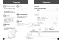
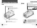
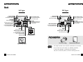
COLOR CCD CAMERA
INSTRUCTION MANUAL
SDC-311 SERIES
SDC-241 SERIES
SALES NETWORK
·SAMSUNG OPTO-ELECTRONICS AMERICA INC.
·SAMSUNG TECHWIN CO., LTD
40 SEAVIEW DIRVE, SECAUCUS N.J
OPTICS & DIGITAL IMAGING DIV.
07094, U.S.A.
145-3, SANGDAEWON 1-DONG, JUNGWON-GU,
SUNGNAM, KYUNGKI-DO, KOREA
TEL : (201) 902-0347
462-121
FAX : (201) 902-9342
TEL : 82 -031-740 - 8121~41
FAX: 82 -031-740 - 8145
www.samsungcctv.com
www.samsungtechwin.com
www.samsungcamerausa.com
P/ NO. : 6806 - 0231- 01C
Printed in Korea
SAMSUNG CCD CAMERA
Thank you for purchasing a SAMSUNG CCD CAMERA.
Before operating the camera, confirm the camera model and proper input power
voltage. In order that you can understand this manual thoroughly, we'll introduce our
model description.
SDC-311 Series (410,000 Pixels)
•NTSC models
• PAL models
– SDC-311ND
– SDC-311PD
– SDC-311NA
– SDC-311PA
– SDC-311PH
SDC-241 Series (270,000 Pixels)
•NTSC models
• PAL models
– SDC-241ND
– SDC-241PD
– SDC-241NA
– SDC-241PA
– SDC-241PH
Model Description
SDC-311 x x
SDC-241 x x
power source
signal system
• Signal System
N → NTSC Model
P → PAL Model
• Power Source
D → DC 12V
A → AC 24V ~
H → High Voltage (PAL Model: AC 230V~ )
2
COLOR CCD CAMERA
CAUTION
RISK OF ELECTRIC SHOCK
DO NOT OPEN
CAUTION :
TO REDUCE THE RISK OF ELECTRIC SHOCK,
DO NOT REMOVE COVER (OR BACK),
NO USER SERVICEABLE PARTS INSIDE.
REFER SERVICING TO QUALIFIED
SERVICE PERSONNEL.
The lightning flash with arrowhead symbol, within an equilateral
triangle is intended to alert the user to the presence of uninsulated
"dangerous voltage" within the product's enclosure that may be of
sufficient magnitude to constitute a risk of electric shock to persons.
The exclamation point within an equilateral triangle is intended to alert
the user to the presence of important operating and maintenance
(servicing) instructions in the literature accompanying the appliance.
INFORMATION - This equipment has been tested and found to comply with
limits for a Class A digital device, pursuant to part 15 of the FCC Rules. These
limits are designed to provide reasonable protection against harmful
interference when the equipment is operated in a commercial environment. This
equipment generates, uses, and can radiate radio frequency energy and, if not
installed and used in accordance with the instruction manual, may cause
harmful interference to radio communications.
Operation of this equipment in a residential area is likely to cause harmful
interference in which case the user will required to correct the interference at his
own expense.
WARNING - Changes or modifications not expressly approved by the
manufacturer could void the user’s authority to operate the equipment.
CAUTION : To prevent electric shock and risk of fire hazards:
◆ Do NOT use other than specified power source.
◆ Do NOT expose this appliance to rain or moisture.
This installation should be made by a qualified service
person and should conform to all local codes.
COLOR CCD CAMERA
3
Features
Automatic Backlight Compensation
The backlight compensation technology
allows the camera to find the best
picture conditions in any environment
and automatically gives a necessary light
level compensation, so that you
can always obtain the clear picture, the
finest detail and perfect light contrast.
Electronic Iris
Electronic iris shutter is automatically
controlled at the speed of
1/60~1/100,000sec(NTSC Models), /
1/50~1/100,000sec(PAL Models).
Video/ DC Selection Switch
High Resolution
The horizontal resolution of 470 TV lines can
be achieved by using a high density CCD
having effective 410,000 pixels, which
provides clean, noiseless and reliable
pictures.
(SDC-241Series have 270,000 pixels and
can achieve 330 TV lines)
High Sensitivity
The camera accepts 2 types of auto iris
lenses(DC type/VIDEO type) and
is set with VIDEO/DC selection switch.
SYNC. System
You can select INT(Internal
Synchronization) mode or L. L(Linelock
Synchronization) mode.
Contents
PRECAUTIONS ....................................................................... 6
GETTING TO KNOW YOUR CAMERA ........................................... 8
Front ........................................................................ 8
Bottom ..................................................................... 9
Back ....................................................................... 10
Accessories ............................................................ 11
CONNECTION .......................................................................
Lens .......................................................................
Installing Auto IRIS Lens ........................................
Installing C/CS -Mount Lens .................................
Connecting to Monitor ............................................
Connecting to Power ..............................................
MENU SETUP .........................................................
TROUBLESHOOTING ................................................
12
12
12
14
16
17
18
20
SPECIFICATIONS ................................................................... 22
We utilize a high sensitivity Sony color CCD
imager. This allows for clear and vivid
images under dark situation as low as a
minimum of 0.4 lux.
4
COLOR CCD CAMERA
COLOR CCD CAMERA
5
Precautions
Do not install the camera in extreme
temperature conditions.
Do not install or use the camera in an
environment where the humidity is high.
Do use the camera under conditions where
temperatures are within -10°C to 50°C.
Especially be careful for ventilation under
high temperature.
It can cause the image quality to be poor.
Do not install the camera under
unstable lighting conditions.
Never use the camera close to a
gas or oil leak.
Severe lighting change or flicker can
cause the camera to work improperly.
Do not drop the camera or subject
them to physical shocks.
It can cause malfunctions to occur.
It can cause malfunctions to occur.
Never keep the camera face to strong
light directly.
It can damage the CCD.
Do not expose the camera to rain or
spill beverage on it.
Do not touch the front glass of the
camera.
If it gets wet, wipe it dry immediately.
Liquids can contain minerals that corrode
the electronic components.
It is one of the most important parts of
camera.
Be careful not to be stained by fingerprint.
Do not disassemble the camera.
There are no user-serviceable
parts inside it.
6
COLOR CCD CAMERA
Notes
•If the camera is exposed
NOTEto spotlight or object reflecting the strong light,
smear or blooming may occur.
•Please check the power whether it satisfies the normal specification
before connecting the camera.
COLOR CCD CAMERA
7
Getting to Know Your Camera
Front
Tripod Mounting Hole
Used to install the camera on an optional
tripod. The tripod must be equipped with
the screw specified as shown below.
Focal Length Adjusting Knob.
Used to adjust Back focal length.
Tripod Mounting Bracket Screw Hole.
Used to fix Tripod mounting bracket on
the top of the camera.
Auto Iris Lens Connector.
Used to connect Auto iris lens plug.
Back Focus Lock Screw.
Used to fix Focal length adjusting knob.
8
Bottom
COLOR CCD CAMERA
1/4”-20 UNC (20 THREAD)
L:4.5mm 0.2mm (ISO standard),
or 0.197”(ASA standard)
L
You can remove and install this bracket
on the top of the camera. You must use
the supplied screw or the equivalent
(within 4mm). If not, the bracket may
not fixed properly.
COLOR CCD CAMERA
9
Back
AC type
Power LED
DC type
Video Output Jack
The LED turned on
when power is supplied.
Used to connect an external
video monitor in jack.
Power LED
Video Output Jack
The LED turned on
when power is supplied.
Used to connect an external
video monitor in jack.
V. PHASE
Used to adjust vertical
phase
Linelock mode from 0~270
Menu Setup Switch
DC Level
DC Level
Used to adjust DC IRIS lens level.
(You can adjust DC level when
ESC mode is off.)
Used to adjust DC IRIS lens level.
(You can adjust DC level when
ESC mode is off.)
Used to choose the desired menu
on or off, select the menu.
Menu Setup Switch
Used to choose the desired menu
on or off, select the menu.
GND
GND
Power ground.
Power ground.
Power Input Terminal
Power Input Terminal
It involved power input.
Use only AC 24V, UL Listed
Class 2 Power Supply
(SDC-311PA)
(SDC-241PA)
It involved power input.
AC24V GND
(SDC-311NA/241NA)
Iris Lens Plug
High Voltage Type
Notes
10
COLOR CCD CAMERA
Instruction Manual
NOTE
•The image has been set for optimum performance at the factory.
Do not remove the cover unless it is absolutely necessary.
It could cause damage to components and problems.
-Be sure to check the power is off when removing the cover.
COLOR CCD CAMERA
11
Connection
Lens
4. Remove the protecting cap, and attach the lens into the camera
by turning clockwise.
Lens is not supplied with this camera. Purchase a lens suitable
for your environment. This camera accepts auto iris lens, both
C- and CS-mount lens.
5. Connect the lens plug to the auto iris connector on the rear of the
camera.
Notes
NOTE
•If the lens is stained
with fingerprint or something, the image quality
might be poor.
•It is recommended to use a high quality lens to improve the image
quality under low illumination.
Installing Auto Iris Lens
1. Peel the end of lens cable outer cover approximately 8mm.
approx.8mm
6. Set the DC/VIDEO selection switch to DC or VIDEO according to
the type of the lens.
2. Peel the end of the cable inner cover approximately 2mm.
approx.2mm
3. Remove the cover from the connector pin supplied, and solder
the lens cable to the connector pin as shown below.
•Video type :
No.1 Pin …
No.2 Pin …
No.3 Pin …
No.4 Pin …
12
Red (Power source)
N. C
White (Video signal)
Black (GND)
COLOR CCD CAMERA
•DC type :
No.1 Pin …
No.2 Pin …
No.3 Pin …
No.4 Pin …
Damping Damping +
No.3 Pin
Drive +
No.1 Pin
Drive -
Cover
Lens cable
Connector
No.4 Pin
No.2 Pin
COLOR CCD CAMERA
13
Installing C/CS-Mount lens
Before mounting a lens, please check whether it is a C-mount or
CS-mount lens.
The back focus has set for CS-mount lens at the factory.
If the mount is changed to the C-mount lens, it may need to
be re-adjusted.
◆ In
case of mounting a C-mount lens
1. After removing the protecting
cap, loosen the Back focus lock
screw with screwdriver.
2. Turn the Focal length adjusting
knob to counterclockwise until
locking.
3. Attach the lens into the camera
by turning clockwise.
4. Turn the Focal length adjusting
knob to clockwise slowly at the
best point.
◆ In case of mounting a CS-mount lens
After removing the protecting cap, attach the lens into the
camera by turning clockwise.
Notes
•Use the lens under theNOTE
specification as shown. Otherwise
the lens can damage the camera or abnormal fixing may be resulted in.
5. Tighten the Back focus lock screw
with screwdriver.
C-mount lens : 10 mm or less
CS-mount lens : 5 mm or less
•A heavy lens may disturb the balance with the camera and possibly results in damage.
Don't use more than 450g lens.
•It is recommended to set the lens ALC mode to Av mode (Average).
Pk mode can be occurred hunting.
14
COLOR CCD CAMERA
Notes
NOTE
•Do not turn the Focal length adjusting knob
too much to clockwise after clicking when
use CS-mount lens.
COLOR CCD CAMERA
15
Connecting to Monitor
Connecting to Power
Connect the VIDEO Out jack to the monitor VIDEO In jack.
Each model has different power specification, please check the name of
the model and power specification before connecting to power source.
Please refer to the sticker identifying the model, which is attached on
the product, for power specification.
CCD Camera
Monitor
AC outlet
220V
100V
AC adaptor
• As a connecting method varies according to instruments, refer to
the manual supplied with the instrument.
220V
•The wire is polarized. Be sure to
connect the wire with white line on
its covering to‘ - ’terminal and
connect the other one to
‘ + ’teminal.
•Use DC 12V power source
for SDC-311(241) ND/PD.
•Use AC 24V~50Hz power source
for SDC-311(241)PA.
(The wire is non-polarized.)
• Connect the cable after power is turned off.
AC24V GND
• Set the 75Ω/Hi-Z selection switch as shown below if you have
intermediate device.
100V
AC adaptor
CCD Camera
Intermediate
End monitor
230V
230V~50Hz
Notes
16
COLOR CCD CAMERA
•The wire is non - polarized.
•Use AC 24V 60Hz power
source for SDC-311(241)NA.
※Connect the wire by pushing the
button
•Use AC 230V~50Hz power source for
SDC-311(241)PH.
NOTEpower after all the installation is done.
•Be sure to connect
•Note that AC adaptor is not supplied with camera.
•Since the wire of DC power type is polarized, be careful when
Connecting it.
COLOR CCD CAMERA
17
Menu Setup
Use the six Setup Menu buttons on the rear of the camera.
Menu Setup Switch
ESC
OFF
FL
BLC ATW VIDEO INT
ON OFF AWC DC
LL
①
②
③
④
⑤
⑥
Electonic Shutter speed Control : OFF
Flickerless
: OFF
Backlight Compensation
: OFF
Auto White Balance
: ATW
LENS Selection
: VIDEO
Sync Mode
: INT
(SDC-241/311 AC power only)
Function of Menu Setup Switch
① ESC (Electronic Shutter Control)
You can turn ESC or OFF the Electronic Shutter Control feature.
This ESC mode automatically controls the shutter speed from‘1/60’
to‘1/100,000 ’sec (NTSC), from‘1/50’to‘1/100,000’sec. (PAL)
If you want to use DC or VIDEO lens, confirm this switch turn OFF.
(Electronic shutter is fixed in‘1/60’sec. (NTSC) or‘1/50’sec (PAL)
② FL (Flickerless)
Flickerless function. In this function, electronic shutter is fixed in
‘1/100’sec(NTSC) or‘1/120’sec(PAL)
FL function can compensation the flicker caused by power
frequently, but set off in the area not using a 60 Hz AC power on NTSC.
③ BLC (Backlight Compensation)
When the lighting source in the rear of object, the object might be
seen some darkness. If you want to see object clearly, turn this
switch BLC. The effective area where backlight compensation is
fixed in the center of the screen.
If you want to use DC or VIDEO lens, confirm this switch OFF.
0
0
7
5
10
④ White balance control mode
1) ATW (Auto Tracing White balance) : The camera automatically
controls the white balance in any environment.
2) AWC (Auto White balance Control) : The White balance is automatically
adjusted in a specific environment.
Notes
NOTE
•Pleace select ESC
OFF that chroma mav be chance periodicallv
because of ATW movement under the fluorescent lights indoor.
⑤ Lens selection
1) Manual Lens
Set Menu Setup switch ESC
2) Auto IRIS Lens
ⓐ VIDEO Lens : Set the ESC OFF in Menu Setup switch, and turn
DC/VIDEO selection switch VIDEO.
If you need, adjust the brightness of the screen
of the screen with adjustment VR(ALC, LEVEL) on
the VIDEO lens.
ⓑ DC Lens
: Set the ESC OFF in the Menu Setup switch, and
the DC/VIDEO selection switch DC.
It may necessary to adjust the bright of the screen.
If you needs, handle the DC LEVEL the rear of the
camera.
⑥ INT/L.L (Synchronization System Mode)
Two synchronization modes are available. In L.L mode, Use V.Phase
adjust relation between the zero crossing point of AC power wave
and V─Sync Pulse of the camera's video signal.
The V.Phase has been set at 220 degrees and can be readjusted
in the range of 0 to 270 degrees as need.
L.L mode can be used in 60Hz (SDC-241/311NA).
50Hz (SDC-241/311PA/PH)
15
⑦ AGC (Auto Gain Control)
Always on.
13
15
18
COLOR CCD CAMERA
COLOR CCD CAMERA
19
Troubleshooting
If you have trouble operating your camera, refer to the following.
If the guidelines do not enable you to solve the problem, contact
an authorized technician.
Problem
Solution
The color of the picture is not • Check that you have properly set White Balance
matched.
Control Mode.
Solution
• Check that the power cord and line connection
between the camera and monitor are made
properly.
Nothing appears on the
screen.
Problem
• Check that the DC/VIDEO selection switch on the
rear of the camera is set to a proper position
according to the type of your auto iris lens.
The contrast on the screen
is too weak.
The image on the screen
flickers.
The image on the screen
is dark.
• Check that you have set ESC feature
The image on the screen
is dim.
• Check if the lens are stained. If
dirty, clean the lens with soft,
clean cloth.
The image on the screen is
distorted.
• Adjust the contrast feature of the monitor.
• If the camera is exposed under too strong light,
change the camera position.
• Does the camera face to directly to the sun or
fluorescent lighting?
Change the camera position.
• Check that the DC/VIDEO selection switch on
the rear of the camera set to a proper position
according to the type of your auto iris lens.
• Check that you have used 50Hz (PAL models),
60Hz(NTSC models) the linelock synchronization
mode cannot be used.
Use the Synchronization Mode to INT mode.
The camera is not work
properly, and the surface
of the camera case is hot.
20
COLOR CCD CAMERA
• Check that you have connected the
camera to a proper power.
COLOR CCD CAMERA
21
Specifications
SDC-311 Series
Item
SDC-241 Series
SDC-311ND SDC-311NA
Power Source
DC 12V
AC 24V
60Hz
Power Consumption
Input Current
4.5W
350mA
6.5W
240mA
SYNC. System
INT Only
Pick-Up Device
SDC-311PD SDC-311PA SDC-311PH
INT/Linelock
DC 12V
4.5W
350mA
AC 24V~ AC230V~
50Hz
50Hz
INT Only
selectable
1/3”CCD, 768(H)×494(V)
6.5W
32mA
6.5W
240mA
INT/Linelock selectable
1/3”CCD, 752(H)×582(V)
Item
SDC-241ND SDC-241NA SDC-241PD SDC-241PA SDC-241PH
Power Source
DC 12V
AC 24V
60Hz
DC 12V
Power Consumption
Input Current
4.0W
320mA
6.0W
240mA
4.0W
320mA
SYNC. System
INT Only
Pick-Up Device
INT/Linelock
AC 24V~ AC230V~
50Hz
50Hz
6.0W
240mA
INT Only
selectable
6.0W
28mA
INT/Linelock selectable
1/3”CCD, 510(H)×492(V)
1/3”CCD, 500(H)×582(V)
2:1 Interlace(NTSC Standard)
2:1 Interlace(PAL Standard)
525 Lines / 60 Fields /30 Frames
625 Lines / 50 Fields / 25Frames
2:1 Interlace(NTSC Standard)
2:1 Interlace(PAL Standard)
525 Lines / 60 Fields /30 Frames
625 Lines / 50 Fields / 25Frames
Video Output
1.0 Vp-p NTSC Comp
1.0 Vp-p PAL Comp
Video Output
1.0 Vp-p NTSC Comp
1.0 Vp-p PAL Comp
Electronic Iris
1/60~1/100,000 sec
1/50~1/100,000 sec
Electronic Iris
1/60~1/100,000 sec
1/50~1/100,000 sec
Scanning System
Scanning System
Minimum Illumlnation
0.7 Lux at F 1.2
Minimum Illumlnation
0.3 Lux at F 1.2
Resolution
≥ 480(H) TV Iines
Resolution
≥ 330(H) TV Iines
Backlight Compensation
ON/OFF Selectable
Backlight Compensation
ON/OFF Selectable
Iris Mode
VIDEO / DC / ESC Selectable
Iris Mode
VIDEO / DC / ESC Selectable
Lens
C / CS Mount Changeable
Lens
C / CS Mount Changeable
AGC
Always On
AGC
Always On
Flickerless
ON/OFF Selectable
Flickerless
ON/OFF Selectable
White Balance
ATW / AWC
White Balance
ATW / AWC
Gamma
γ=0.45
Gamma
γ=0.45
S/N Ratio
≥ 48dB (AGC OFF)
S/N Ratio
≥ 48dB (AGC OFF)
10°C~+50°C
Ambient Temp
Dimension
Weight
320g
(Without
Lens)
Accessory
530g
(Without
Lens)
320g
(Without
Lens)
530g
(Without
Lens)
Iris jack, Instruction Manual
Design and specifications are subject to change without notice.
22
COLOR CCD CAMERA
10°C~+50°C
Ambient Temp
55(W)×50(H) ×121(L) mm (Without Lens)
550g
(Without
Lens)
Dimension
Weight
Accessory
55(W)×50(H) ×121(L) mm (Without Lens)
320g
(Without
Lens)
530g
(Without
Lens)
320g
(Without
Lens)
530g
(Without
Lens)
550g
(Without
Lens)
Iris jack, Instruction Manual
Design and specifications are subject to change without notice.
COLOR CCD CAMERA
23