1
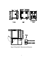
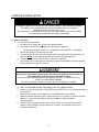
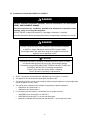
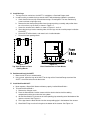
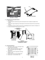
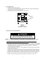
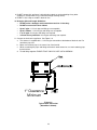
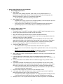
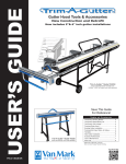
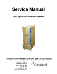
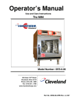
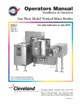
Installation Manual PATENT PENDING Energy Star SteamChef Models 22CET3.1 and 22CET6.1 1333 East 179th Street Cleveland, Ohio 44110 Phone: (216) 481 - 4900 1-800-338-2204 Fax: (216) 481 - 3782 www.clevelandrange.com Part No. 22CET(ES)-INM REV. C 5/07 FOR YOUR SAFETY Do not store or use gasoline or other flammable vapors or liquids in the vicinity of this or any other appliance. Improper installation, adjustment, alteration, service, or maintenance can cause property damage, injury, or death. Read the installation, operating and maintenance instructions thoroughly before installing or servicing this equipment. ELECTRIC SHOCK HAZARD DEATH, INJURY, or EQUIPMENT DAMAGE can result from touching any component inside this appliance when the power is connected. Whenever possible disconnect the power while installing, servicing, or testing. When installation, service, or tests require power to be connected; use extreme caution and every possible precaution and safety measure while installing, servicing, or testing this appliance. Do not connect the drain connection to any drain material that cannot sustain 180o Fahrenheit. Using drain material that cannot withstand 180o Fahrenheit can result in injury, equipment damage, and property damage. WARNING This appliance is constantly hot whenever the main power lever is ON, the door is closed and the reservoir is filled with water. When the selector switch of this appliance is turned to the OFF position, this appliance remains hot by maintaining the Standby temperature in the cooking compartment. ALL SERVICE MUST BE PERFORMED BY A QUALIFIED CLEVELAND RANGE AUTHORIZED TECHNICIAN KEEP THIS MANUAL FOR REFERENCE This manual may be subject to new technical developments, modifications, and unforeseen errors. DO NOT INSTALL OR OPERATE OR ATTEMPT TO INSTALL OR OPERATE THIS APPLIANCE OR ANY ACCESSORIES WITHOUT READING COMPLETELY AND FULLY UNDERSTANDING THIS MANUAL Cleveland Range appliances are intended for other than household use. Cleveland STATEMENT OF POLICIES LIMITED WARRANTY CLEVELAND RANGE products are warranted to the original purchaser to be free from defects in materials and workmanship under normal use and service for the standard warranty period of one year from date of installation or 18 months from date of shipment, which ever comes first. CLEVELAND RANGE agrees to repair or replace, at its option, f.o.b. factory, any part which proves to be defective due to defects in material or workmanship during the warranty period, providing the equipment has been unaltered, and has been PROPERLY INSTALLED, MAINTAINED, AND OPERATED IN ACCORDANCE WITH THE CLEVELAND RANGE OWNER’S MANUAL. CLEVELAND RANGE agrees to pay any FACTORY AUTHORIZED EQUIPMENT SERVICE AGENCY (within the continental United States, and Hawaii) for reasonable labor required to repair or replace, at our option, f.o.b. factory, any part which proves to be defective due to defects in material or workmanship, during the labor warranty period. This warranty includes travel time not to exceed two hours and mileage not to exceed 50 miles (100 miles round-trip), BUT DOES NOT INCLUDE POST START-UP, TIGHTENING LOOSE FITTINGS, MINOR ADJUSTMENTS, MAINTENANCE, CLEANING OR DESCALING. The standard labor warranty allows factory payment of reasonable labor required to repair or replace such defective parts. Cleveland Range will not reimburse the expense of labor required for the repair or replacement of parts after the standard warranty period, unless an Extended Labor Warranty Contract has been purchased to cover the equipment for the balance of the warranty period from the date of equipment installation, start-up, or demonstration. PROPER INSTALLATION IS THE RESPONSIBILITY OF THE DEALER, THE OWNER-USER, OR INSTALLING CONTRACTOR, AND IS NOT COVERED BY THIS WARRANTY. Many local codes exist, and it is the responsibility of the owner and installer to comply with these codes. Cleveland Range equipment is built to comply with applicable standards for manufacturers, including UL, ANSI, NSF, ASME/Ntl. Bd., CSA, and others. BOILER (Steam Generator) MAINTENANCE IS THE RESPONSIBILITY OF THE OWNER-USER AND IS NOT COVERED BY THIS WARRANTY. The use of good quality feed water is the responsibility of the Owner-User (see Water Quality Recommendations below). THE USE OF POOR QUALITY FEED WATER WILL VOID EQUIPMENT WARRANTIES. Boiler maintenance supplies, including boiler hand hole gaskets, are not warranted beyond the first 90 days after the date the equipment is placed into service. Preventive maintenance records must be available showing descaling per applicable Cleveland Operator Manual for Boiler Proration Program considerations. WATER QUALITY RECOMMENDATIONS TOTAL DISSOLVED SOLIDS TOTAL ALKALINITY SILICA CHLORIDE pH FACTOR less than 60 parts per million less than 20 parts per million less than 13 parts per million less than 30 parts per million greater than 7.5 The foregoing shall constitute the sole and exclusive remedy of original purchaser and the full liability of Cleveland Range for any breach of warranty. THE FOREGOING IS EXCLUSIVE AND IN LIEU OF ALL OTHER WARRANTIES, WHETHER WRITTEN, ORAL, OR IMPLIED, INCLUDING ANY WARRANTY OF PERFORMANCE, MERCHANTABILITY, OR FITNESS FOR PURPOSE, AND SUPERSEDES AND EXCLUDES ANY ORAL WARRANTIES OR REPRESENTATIONS, OR WRITTEN WARRANTIES OR REPRESENTATIONS, NOT EXPRESSLY DESIGNATED IN WRITING AS A “WARRANTY” OR “GUARANTEE” OF CLEVELAND RANGE MADE OR IMPLIED IN ANY MANUAL, LITERATURE, ADVERTISING BROCHURE OR OTHER MATERIALS. CLEVELAND RANGE’S liability on any claim of any kind, including negligence, with respect to the goods or services covered hereunder, shall in no case exceed the price of the goods or services, or part thereof, which gives rise to the claim. IN NO EVENT SHALL CLEVELAND RANGE BE LIABLE FOR SPECIAL, INCIDENTAL, OR CONSEQUENTIAL DAMAGES, OR ANY DAMAGES IN THE NATURE OF PENALTIES. LIMITED EXTENDED WARRANTY COVERAGE The purchase of a Limited Extended Warranty Contract extends the standard warranty coverage to the purchased period of time (one to two years) from the date of installation, start-up, or demonstration, whichever is sooner. *An additional two years Parts and Labor Warranty can be purchased with each piece of Cleveland equipment for an additional 2% of the List Price per year. The 2% of list price charge will be the net invoice amount for each year of extended warranty purchased. - Extended warranty must be purchased at the same time the equipment is purchased. - Extended Warranty has the same exclusions as stated in our standard warranty. Second year limited extended warranty coverage on Cleveland Steamers when purchased with a water filter applies to water related components only. INSTALLATION MANUAL SteamChef 22CET3.1 and 22CET6.1 Table of Contents Chapter.....................................................................................................................Page 1 Product Information ................................................................................................... 1 A. Product Information ............................................................................................................................ 1 B. Product Information Plate .................................................................................................................. 1 2 General Information ................................................................................................... 2 A. Laws, Codes, and Regulations .......................................................................................................... 2 B. Inspect for Shipping Damage ............................................................................................................ 2 C. Product Views...................................................................................................................................... 3 3 Installation .................................................................................................................. 5 A. Select a Location................................................................................................................................. 5 B. Installation of a SteamChef 22CET3.1 or 22CET6.1 ......................................................................... 6 C. Install the Legs .................................................................................................................................... 7 D. Position and Level the 22CET ............................................................................................................ 7 E. Install the KleanShield™..................................................................................................................... 7 F. Install the Fan Guard and Air Diverter ............................................................................................... 8 G. Install the Slide Racks (Pan Racks) ................................................................................................... 8 H. Install the Rear Vent ............................................................................................................................ 9 I. Connect the Free Air Vented Drain Line ............................................................................................. 9 J. Water Supply Requirements and Installation.................................................................................. 11 K. Electric Power Supply ...................................................................................................................... 13 L. Installation Checklist......................................................................................................................... 14 4 Operating Tests ........................................................................................................ 15 A. Startup Procedure ............................................................................................................................. 15 B. Drain Rinse Inspection ..................................................................................................................... 16 C. Operating Tests and Final Checkout Procedure ............................................................................ 16 D. Shutdown ........................................................................................................................................... 18 5 Installer’s Troubleshooting Guide .......................................................................... 19 CHAPTER 1 PRODUCT INFORMATION A. Product Information • This manual covers the installation of 22CET3.1 and 22CET6.1 SteamChef Steam Cookers (steamers), and their standard features and options. • Other than selection of options, there are presently no significant design, parts, or operating differences among appliances with this model number. • Figures 2-1 and 2-2 illustrate the dimensions, clearances, and major external features of 22CET’s. B. Product Information Plate The Product Information Plate on the back of the appliance lists: • Model • Serial Number • Power and Wiring Requirements 1 CHAPTER 2 GENERAL INFORMATION A. Laws, Codes, and Regulations This equipment should be installed only by qualified, professional plumbers, pipe fitters, and electricians. 1. The installation of this appliance must conform with: a. The National Electrical Code, ANSI/NFPA 70 (latest edition), or the Canadian Electrical Code, CSA C22.2, or local codes, as applicable. • 2. 3. 4. 5. When installed, the appliance must be electrically grounded in accordance with the above. • NOTE: This appliance is not GFI (GFCI) compatible. b. The Food Code (latest edition) of the Food and Drug Administration (FDA). This equipment is to be installed to comply with the applicable federal, state, or local plumbing codes. Installation instructions must be read in their entirety before starting installation of this appliance. Install this appliance according to the policies and procedures outlined in this manual. Installation must comply with all local fire and health codes. Improper installation, adjustment, alteration, service, or maintenance of this appliance, or installation of a damaged appliance can result in DEATH, INJURY, EQUIPMENT DAMAGE, and void the warranty. NEVER install damaged appliances, equipment, or accessories. ALWAYS have installation and service performed by qualified Cleveland Range authorized personnel. B. Inspect for Shipping Damage • 1. 2. 3. If the appliance is damaged or damage is suspected: Submit a Damage Claim to the Shipper immediately. Inform your dealer at once. Inform Cleveland Range in writing within three (3) days. 2 C. Product Views 32.162 21.625 30.177 21.625 18.359 22.395 22.395 28.000 C1 30.177 3.000 12.000 90° 24.000 Figure 2-1 SteamChef 3.1 Dimensions and Clearances 3 C2 32.162 21.625 30.177 26.750 26.913 30.949 30.750 C1 C2 4.000 28.000 28.000 29.331 120° 30.177 12.000 90° 24.000 Figure 2-2 SteamChef 6.1 Dimensions and Clearances 4 CHAPTER 3 INSTALLATION Operating this appliance out of level can cause DEATH, INJURY, and EQUIPMENT DAMAGE. This appliance must be level both front-to-back and side-to-side in all installations. NEVER operate this appliance out of level. If this appliance is suspected to be out of level, shut it down at once and call your qualified Cleveland Range authorized service agency immediately. A. Select a Location 1. For safe and efficient operation: a. Installation must comply with all local fire and health codes. b. The location selected must be capable of supporting this appliance. • The operating weight of a 22CET3.1 is 270 pounds and a 22CET6.1 is 350 pounds. c. Position the appliance so it will not tip or slide. d. The operating surface must be level enough to allow leveling with the adjustable legs. This appliance MUST be level both front to back and side to side before operation. e. A suitable drain must be available within 12 feet of this appliance. f. The location must include space for Operating and Service/Secondary Clearances and the Exhaust Hood. See Figures 2-1 and 2-2. All clearance requirements above, below, and around this appliance are the same for non-combustible locations as for combustible locations. Failure to maintain required clearances and additional distances as needed can result in INJURY and EQUIPMENT DAMAGE. Consult manufacturers’ literature, and sales and service agencies as needed. g. KEEP THE APPLIANCE AREA FREE AND CLEAR OF COMBUSTIBLES. h. Proper air supply for ventilation is REQUIRED for and CRITICAL to safe, efficient operation of this appliance. i. Make sure the air vents of this appliance are not blocked with or by anything. j. Allow for sufficient extra distance if a "high heat source," e.g. a broiler, is located next to this appliance. Contact Cleveland Range at 216-481-4900 or 1-800-338-2204 for recommendations. k. Do NOT install this appliance directly over a drain. Steam rising up out of the drain will adversely affect operation, hamper cooling air circulation, and damage electrical and electronic components. 5 B. Installation of a SteamChef 22CET3.1 or 22CET6.1 DANGER Improper installation, adjustment, alteration, service or maintenance can cause DEATH, INJURY, AND EQUIPMENT DAMAGE Read and understand the installation, operation and maintenance instructions before installing, using, or servicing this equipment. DO NOT INSTALL a SteamChef steamer if it is damaged or if damage is suspected. Install the SteamChef steamer according to the policies and procedures outlined in this manual. DANGER Improper Lifting can cause DEATH, INJURY, and EQUIPMENT DAMAGE A 22CET3.1 weighs 270 pounds, and a 22CET6.1 weighs 350 lbs. Use enough workers with experience lifting heavy equipment to place the appliance on the supporting surface. CAUTION Attempting to operate an improperly installed or out of level steamer or shifting the steamer while operating can cause injury and equipment damage. The steamer must be LEVEL both FRONT-TO-BACK and SIDE-TO-SIDE and PROPERLY INSTALLED in all mounting arrangements. Do NOT shift or move the steamer while it is operating. Do NOT operate an improperly installed steamer. 1. 22CET’s are typically installed with four adjustable legs. See Figures 2-1 and 2-2. 2. The appliance must be level both front-to-back and side-to-side. 3. The operating surface must be level enough to allow leveling the appliance using the adjustable legs of the appliance or the stand. 4. The counter area selected must be capable of supporting an operating weight of: • 270 pounds for a SteamChef 3.1. • 350 pounds for a SteamChef 6.1. 5. If a satisfactory counter location is not available use an equipment stand: • UNISTAND 34 for one 22CET3.1 or 22CET6.1. • UNISTAND 25 for two 22CET3’s, one on top of the other. • Model No. ES263044 Stacking Stand for two 22CET6.1’s, one on top of the other. 6 C. Install the Legs 1. The legs must be used unless the 22CET is installed on a Cleveland Range stand. 2. In order to safely assemble the legs onto the 22CET without damage, follow this procedure: a. Check that the feet are fully retracted into the legs. Do not tighten. The feet should easily screw in and out using fingers only. b. Remove the four foam packing blocks from the upper packing assembly, and position them on a flat surface (e.g. the floor) as shown in Figure 3-1. c. Center the steamer on the blocks as shown in Figure 3-1 and 3-2. d. Screw the four legs into the mounting holes. All four legs must be used for proper installation of a 22CET. e. Lift the 22CET off the blocks, and move it to its installed location. f. Discard the foam packing blocks. Figure 3-1 Top View Steamer on Foam Packing Blocks Figure 3-2 Front View Steamer on Foam Blocks D. Position and Level the 22CET 1. Move the 22CET to its installed location. 2. Using a level, adjust the legs of the 22CET or the legs of the Cleveland Range stand until the 22CET is level front-to-back and side-to-side. E. Install the KleanShield™ a. Never operate a SteamChef Steamer without a properly installed KleanShield. b. To install the KleanShield: 1) Remove the slide pan racks. 2) Place the KleanShield into the steamer with the drain to the back of the cooking compartment and the pipe extension facing down. 3) Set the KleanShield in place over the corresponding pipe extending out of the bottom of the steamer reservoir. See Figure 3-3. 4) Fit the pipe from the KleanShield into the corresponding pipe in the bottom of the steamer. 5) KleanShield™ legs must be flush against the bottom of the steamer. See Figure 3-4. 7 Drain Legs FIT UP OF KLEANSHIELD PIPE Figure 3-4 KleanShield Figure 3-3 KleanShield Installation (SteamChef 3.1 shown) F. Install the Fan Guard and Air Diverter • See Figure 3-5 1. Hold the fan guard so that the large ends of the keyhole slots are towards the bottom of the steamer. 2. Place all four large end openings of the keyholes over the mounts located on the rear wall of the steamer. 3. Pull it down so that the narrow ends of the slots are pulled tight over the mounts. See Figure 3-5. 4. Place the air diverter onto the fan guard as shown. FAN GUARD LARGE END OF KEYHOLES AT BOTTOM FAN GUARD SHOWN PULLED DOWN TO LOCK IT IN PLACE AIR DIVERTER Figure 3-5 Fan Guard Shown Installed (SteamChef 3.1 Shown) G. Install the Slide Racks • 1. 2. 3. 4. See Figure 3-6. Each rack has four loops: two at the top and two at the bottom. Hold the slide rack so the ends of the hanger loops are toward the side of the cooking compartment. Slide one rack into the compartment with loops toward one side. Hook the loops over the top and bottom pins. Repeat steps 1 to 3 for the other racks. 8 Figure 3-6 Slide Rack H. Install the Rear Vent • For 22CET’s not on stacking stands: 1. Using pipe thread sealant (not provided), install the provided brass street ell into the bulkhead fitting on the rear of the 22CET. See Figure 3-7. 2. Connect the drain to a free air vented drain line. See Figure 3-8. VENT DRAIN Figure 3-7 Steam Vent (SteamChef 3.1 Shown) I. Connect the Free Air Vented Drain Line DEATH, INJURY, EQUIPMENT and PROPERTY DAMAGE will result from improper installation of drain outlet lines. Install free air vented drain lines as described in this manual. NOTICE: Furnishing and installing drain lines and drainpipe is the responsibility of the Installer/Owner. The following restrictions and requirements are critical to the safety of personnel and equipment, and must not be violated under any circumstances: 1. The drain lines must be installed in compliance with the Food Code (latest edition) of the Food and Drug Administration (FDA), and any other applicable national, state, or local codes and regulations. 2. The drain line must be free air vented, have gravity flow from the appliance, and terminate outside the perimeter of the appliance. 3. Free air venting requires a minimum 1” clearance between the end of the drain line and the top of the floor drain. See Figure 3-8. 4. Do NOT install the appliance directly over a drain. Steam rising up out of the drain will adversely affect operation, hamper cooling air circulation, and damage electrical and electronic components. o 5. Do NOT connect the appliance’s drain connection to any drain material that cannot sustain 180 F. 6. Do NOT connect any other drain from any other equipment to the drain line of this appliance. 7. Do NOT connect the drain outlet extension line directly into a floor drain or a sewer line. 9 8. Do NOT connect this appliance’s drain directly to drains or to the plumbing of any other equipment. (Except when using a Cleveland Range Stacking Stand.) 9. Do NOT install a trap or shutoff in the drain line. 10. Drainpipe Size and Length Guidelines: • Do NOT make a drainpipe outlet extension more than 12 feet long. • Do NOT use more than three elbows. • Up to 6’ pipe: 1 1/2-inch pipe and fittings are acceptable. • Up to 2 elbows: 1 1/2-inch pipe and fittings are acceptable. • 6’ to 12’ pipe: 2-inch pipe and fittings are required. • 3 elbows on any extension: 2-inch pipe and fittings are required. 11. Connect the drain to the appliance. See Figure 3-8. a. The steamer is supplied with a 1 1/4-inch pipe connection at the bottom of the drain tee. Do not reduce pipe size. b. Make sure the drain pipe is the correct size. See Item 10. c. While assembling the pipes and fittings of the drain outlet extension, use non-hardening pipe thread sealant. d. Thread fittings together FINGER TIGHT ONLY! DO NOT USE A WRENCH! 1" Clearance Minimum Figure 3-8 Typical Drain Connection (SteamChef 3 Shown) 10 J. Water Supply Requirements and Installation 1. Water Supply Requirements a. Water Quality Unlike most steam cooking equipment, water quality can vary without major loss of performance of a SteamChef steamer. Even hard water will not affect the operation of a SteamChef Steamer as long as it is cleaned with vinegar daily. • See the Operator’s Manual for cleaning instructions. b. Water Supply System • A potable water supply system must be available providing a minimum dynamic pressure of 35 psi and a maximum static pressure of 60 psi. • If the static pressure is above 60 psi, a pressure regulator must be used and set at approximately 50 psi. Pressure above 60 psi can damage the solenoid valves. 2. Install the Water Supply Lines Installation Requirements: • The Garden Hose Thread (GHT) connector used must be NSF rated for food grade service. • Do NOT apply pipe thread sealant to NHT or GHT connections. • Apply non-hardening pipe thread sealant to all other threaded connections. • Install a manual water shut-off valve (Main Water Shutoff Valve) (not provided) between the cold water supply line(s) and the appliance. • The National Sanitation Foundation (NSF) requires installation of a check valve (or other approved anti-backflow / anti-siphon device) (not provided) in all supply lines in accordance with and as required by local, state, and national health, sanitation and plumbing codes. • Flush the water supply lines before connecting the lines to the appliance. a. Connect the Water Supply Lines • The Installer/Owner is responsible for the water connection of this appliance. • This appliance is to be installed to comply with all applicable federal, state, or local plumbing codes. Connect this appliance to COLD WATER The condenser system and steam generator will not work properly if they are connected to HOT or WARM water. b. Water supply must have a minimum dynamic (flow) pressure of 35 psi and a maximum static pressure of 60 psi. c. If the static pressure is above 60 psi, a pressure regulator must be used and set at approximately 50 psi. Pressure above 60 psi can damage solenoid valves. See Figures 3-10 and 3-11. d. Install a manual water valve between the main cold water supply line(s) and the steamer supply lines. e. The National Sanitation Foundation (NSF) requires installation of a check-valve (or other approved anti-backflow / anti-siphon device) (not provided) in all supply lines in accordance with and as required by local, state, and national health, sanitation, and plumbing codes. • Check local codes to determine exactly what type of anti-backflow / anti-siphon device is necessary to meet local requirements. f. Design the water supply line(s) so the unit can be moved for service. g. If the supply water meets the requirements shown in the Warranty, then the Single Water Supply Arrangement shown in Figure 3-10 may be used. • If using the single water supply arrangement: The supply piping to the tee fitting must be at least the next larger size of pipe than the connection provided on the appliance. h. Although, 22CET’s are very tolerant of hard water, the owner may want to use conditioned • 11 i. water to supply the reservoir. To use a separate conditioned water supply, use the layout shown in Figure 3-11. The steamer has two 3/4-inch GHT fittings, one for the water reservoir and one for the condenser. See Figures 2-1 and 2-2. A Filter Washer (dirt filter) is supplied installed in each of the water inlets. See Figure 3-9. 1. Construct all supply lines up to the 3/4-inch NHT fittings. 2. Flush the water supply lines before connecting them to the 3/4-inch fittings. Figure 3-9 Filter Washer (P/N 110987 Shown) 3. Test Water Supply Lines a. Check all connections for proper tightness. b. Remove the control side panel to inspect water connections inside the steamer. c. Open the water supply valves. d. Check all lines and connections for leaks, both inside and outside the steamer. SteamChef Water Connection Air/Water Column (if required) Check Valve Condenser Main Cold Water Supply Water Reservoir Water Connection Pressure Reducer (if required) Main Water Shutoff Valve Figure 3-10 Cleveland Range Single Water Supply Arrangement Water Connection Check Valve SteamChef Air/Water Column (if required) Cold Tap Water Supply Condenser Pressure Reducer (if required) Water Connection Main Water Shutoff Valve Water Reservoir Conditioned* Cold Water Supply Figure 3-11 Cleveland Range Separate Water Supply Arrangement when Using Separate Conditioned Feed Water Supply * “Conditioned” indicates water that has been filtered or treated by a Cleveland Range approved method to meet or exceed the water quality standards listed in the Warranty 12 K. Electric Power Supply • The electric supply must match all electrical and wiring requirements specified on the rating plate. • NOTE: This appliance is NOT Ground Fault Interrupter (GFI or GFCI) compatible. • The Electrical Diagram is located on the back of the control-side cover. This appliance is not GFI (GFCI) compatible. Do not use a GFI (GFCI) circuit. Using a GFI (GFCI) circuit can result in injury, equipment damage, and property damage. The connection must be made as follows: 1. Install a main disconnect switch and a separate fuse or breaker for this appliance as shown in Figure 3-12. The fused disconnect switch is called the “Main External Power Switch.” 2. Do not use a GFI (GFCI) circuit. This appliance is not GFI compatible. 3. Do NOT use a power cord. 4. Make the electrical connection using flexible conduit, per local code. 5. There should be a sufficient length of flexible conduit between the steamer and the wall so the appliance can be moved for service. 6. Mechanically secure the flexible conduit to the electrical access hole found at the rear of the appliance. See Figure 3-13. 7. Refer to the wiring diagrams and Figure 3-14. Connect the wires to the terminal block and ground connector. 8. The appliance must be electrically grounded by the installer. ELECTRICAL INLET Figure 3-12 Electrical Layout Figure 3-13 Electrical Connection Inlet WIRING INLET GROUND LUG TERMINAL BLOCK Figure 3-14 Electrical Connections 13 L. Electric Power Supply TASK REFERENCE Preparation Page No. Make sure electric power requirements are met 1, 13 Check operating location clearances 3 Make sure location and exhaust hood requirements are met 5 Check field assembly of the 22CET 5 Check field assembly of stand (if used) 6, Separate Instructions Installation Make sure 22CET is level 7 Check drain line connection 9 Check water supply connection 11 Leak test water supply lines 12 Check electrical line connection 13 Perform Operating Tests 15 2. Notes 14 COMPLETED CHAPTER 4. OPERATING TESTS Operating Tests and Final Checkout Procedure • This procedure must be performed by a qualified Cleveland Range authorized service representative. • Complete the Startup Procedure before starting the actual operating tests. • Read and understand all steps of this procedure before starting. • This procedure evaluates the function of the major operating controls of a SteamChef. • This procedure is for SteamChefs equipped with a Keypad Control Panel, Dial Timer Control Panel, or an ON/OFF Control Panel. • NOTE: The ON/OFF control works like the manual operation of the Timer model EXCEPT that a selector switch is used to turn the cooking function from Standby Heat (OFF) to the Cooking Mode (ON). A. Startup Procedure 1. Set the ON/OFF Lever to the OFF position and open the steamer door. There should be no water in the steamer. 2. Make sure that the KleanShield and reservoir drains are clear (See Figure 4-1). 3. Check for proper installation of the KleanShield, fan guard, backplate, slide racks (See Figure 42), and door gasket assembly. KLEANSHIELD DRAIN OPENING AND OVERFLOW REMOVABLE PAN RACKS FAN GUARD and BACKPLATE RESERVOIR DRAIN OPENING KLEANSHIELD WATER LEVEL PROBE Figure 4-1 Inspecting Compartment drains (SteamChef 6.1 Shown) 4. 5. 6. 7. 8. 9. 10. Figure 4-2 Inspecting Compartment Interior Accessories (SteamChef 3.1 Shown) Make sure the Main External Power Switch is OFF. Make sure the fuses or breakers are the proper size. Remove the control side access cover. Check the internal wiring and make sure there are no loose or disconnected wires. Make sure the supply wiring is the correct size. Check that the appliance is properly grounded. Correct any deficiencies. 15 B. Drain Rinse Inspection (continue from Startup Procedure) 1. Turn OFF the ON/OFF lever/switch. 2. Turn ON the water supply to the steamer. 3. Turn ON the Main External Power Switch. 4. The 3-minute drain rinse cycle starts. 5. The drain is flushed with fresh water. 6. Stop the drain rinse cycle before it is complete by setting the ON/OFF lever to the ON position. 7. Drain rinse stops. 8. The operating control circuits energize. 9. The green Power ON and amber SureCook (Timer Models only) indicators on the control panel light. 10. The reservoir begins to fill with water. 11. Restart the drain rinse cycle by setting the ON/OFF lever to the OFF position. 12. During the drain rinse cycle, make the following checks: a. The ON/OFF lever must be turned fully to the OFF position to start the drain rinse cycle. b. Look at the one-inch vent gap between the steamer drainpipe and the floor drain. A steady stream of water drains from the steamer. c. Check for plumbing leaks. d. After about 3 minutes, the cycle is complete. e. Look at the one-inch vent gap between the steamer drainpipe and the floor drain. No more water drains from the steamer. C. Operating Tests and Final Checkout Procedure (Continue from Drain Rinse Inspection) 1. Set the controls: a. Turn ON the Main External Power Switch. b. Turn OFF the ON/OFF lever. (Timer Models: The green and amber indicators on the control panel are not lit.) c. Set the TIMED/MANUAL switch to TIMED. (ON/OFF models the ON/OFF switch is OFF.) d. Set the timer to zero by turning the dial counterclockwise until it points to the 0 mark. 2. Open the cooking compartment door. 3. Turn ON the ON/OFF lever. The reservoir begins to fill with water. 4. As the reservoir fills with water, check that the green Power ON and amber SureCook indicator lights turn ON. 5. Close the compartment door to close the door interlock circuit. 6. As the water level in the compartment reservoir rises: a. No water flows from the drain opening. b. Check for plumbing leaks in the control compartment. 7. When the water in the reservoir reaches the level of the lower probe, the heating elements and the convection fan turn ON and the steamer heats to the standby temperature. 8. Open the door; the heating elements and convection fan turn OFF. a. The water level in the reservoir continues to rise. b. The water in the reservoir stops rising when water reaches the upper probe. • If the water level continues to rise above the tip of the higher probe, turn OFF the ON/OFF lever and see the Operators Troubleshooting Guide. • If the problem persists, shut down the appliance and call a qualified Cleveland Range authorized service representative. 16 9. Close the compartment door. a. The door interlock circuit closes. b. The heating elements and the convection fan turn ON. c. The cooking compartment heats until the standby temperature is reached. d. When the standby heat temperature is reached, the SureCook indicator light, the convection fan, and the heating elements turn OFF. e. Leave the steamer in timed mode for a few minutes. The SureCook indicator light, heating elements and convection fan cycle ON and OFF as the controls maintain the standby temperature in the cooking compartment. 10. Set the TIMED/MANUAL switch to MANUAL, or for ON/OFF Models turn the switch ON. a. The steaming cycle starts. b. Check the following functions: 1) The heating elements and convection fan turn ON. 2) The water heats to steam. 3) After a few minutes, the cooking compartment reaches steaming temperature. 4) The heating elements and convection fan will stay ON as long as the steamer remains in manual mode (or ON for ON/OFF models). The condenser water will cycle to maintain a drain temperature below 140°F. 5) After several minutes of steaming, check for steam leaks around the door gasket. 6) In manual mode (or ON for ON/OFF Models) the steamer continues to operate at the cooking temperature for up to 60 minutes, or until it is set to the timed mode. NOTE: After 60 minutes of continued operation in the Manual Mode without opening the doors, or switching the steamer to the Timed Mode (or for an ON/OFF model left ON), the cooking compartment temperature automatically lowers to the standby temperature. To return the unit to the cooking temperature, open and close the compartment door. 11. As the appliance continues to steam in Manual Mode, test the no-water/low water safety circuit. a. Close the manual water supply valve(s). b. When the water level drops below the lower water safety cutoff point (the lower probe). The heating elements, the condenser water flow and convection fan will automatically shutoff, and the production of steam will cease. c. Open the manual water supply valve(s). • 12. 13. 14. 15. 16. • The reservoir refills with water to the safety level and steaming resumes. Set the TIMED/MANUAL switch to TIMED and set the Timer to zero. a. The steam generating cycle stops. b. The heating elements, condenser, and convection fan turn OFF. c. The buzzer sounds for 3 seconds. d. Steam production stops and the compartment returns to standby mode. Open the cooking compartment door and allow the compartment to cool for 3 minutes, then close the door and continue testing. Set the TIMED/MANUAL switch to TIMED. Set the Timer for 10 minutes. As soon as the Timer is set, the steam generating cycle starts. This is the same sequence observed in manual mode, except: a. The Timer controls the cycle. b. The elapsed time to produce steam is shorter because the water in the steam generator and the cooking compartment are already hot. c. The cooking compartment returns to Standby temperature after the Timer counts down to zero. 17 17. After timed operation starts, check the following: a. The heating elements and convection fan turn on immediately. b. The SureCook indicator light may turn ON depending on compartment temperature. The SureCook indicator remains ON until the compartment reaches the minimum cooking temperature. c. When the SureCook indicator turns OFF, the Timer begins counting down to zero and the condenser cycles as needed. d. As steam is generated, the water level fluctuates and the solenoid makes a clicking sound when it opens and closes the fill valve. e. Check for steam leaks around the door. f. When the timer counts down to zero, the heating elements, the condenser flow and convection fan turn OFF, and the buzzer sounds for 3 seconds. g. After about 30 seconds steam stops being produced. 18. Go to step D, “Shutdown.” • D. Shutdown (Continue from Operating Tests and Final Checkout Procedure) 1. Turn the steamer OFF by turning the ON/OFF lever/switch counterclockwise to the OFF position. a. The green Power ON indicator light turns OFF. b. The 3-minute automatic drain rinse cycle starts. 2. When the drain rinse is complete, turn the steamer OFF at the main external power switch. 3. Replace the side panels and secure them with their screws. 4. After completing the Startup, Drain Rinse Inspection, and the Operating Tests and Final Checkout Procedure, the appliance is ready for service. 18 CHAPTER 5 INSTALLER’S TROUBLESHOOTING GUIDE The Troubleshooting Guide is a list of symptoms of problems that may occur during routine operation. • “Problem” (left column) lists common operating problems. • “Possible Cause” (center column) lists causes of problems in the order they should be checked. • “Remedy / Reference” (right column) lists fixes for problems from easiest to hardest. • “Notes” in “Remedy / Reference column are at end of the Troubleshooting Guide. ATTEMPTING TO REPAIR OR CORRECT PROBLEMS REQUIRING A QUALIFIED CLEVELAND RANGE AUTHORIZED SERVICE REPRESENTATIVE VOIDS THE WARRANTY Operator’s Trouble Shooting Guide PROBLEM Power indicator light does not turn ON when ON/OFF lever is in the ON position. Power ON and appliance does not fill with water. POSSIBLE CAUSE Power turned OFF at Main External Power Switch. ON/OFF lever not fully turned to the ON position. Inoperative controls or indicators. Water supply to appliance shut OFF. Water line strainer and/or external filter system clogged. Water sensor is grounded by detergent film, or scale. Inoperative controls or solenoids. Control panel Power indicator is on, buzzer sounds continuously, Reset indicator is lit. Compartment bottom dirty with food drippings. Control panel Power indicator light ON and steamer does not heat to cooking temperature or produce steam. REMEDY/REFERENCE Turn ON power at Main External Power Switch. Turn lever to the ON position. See Note 1 Open water supply lines. Clean water supply strainer and/or filter system. See Yearly Maintenance in Operator’s Manual. Clean water sensor assembly with vinegar solution. See Operator’s Manual. See Notes 1 and 5. High limit has been tripped. Reset steamer. If problem repeats, see Note1. Inoperative controls. See Note 1. KleanShield not installed. Juices and/or food leaking from pans or spilling during loading and unloading. Door interlock switch not engaged. Water supply to steamer closed. Water line strainer and/or external filter system clogged. Install KleanShield. Put a solid pan under perforated pans to catch drippings. Put less food in pans. Close door completely. Open water supply lines. Clean water supply strainer and/or filter system. See Yearly Maintenance in Operator’s Manual. Change to manual mode or set the timer. Appliance is in the Timed Mode and timer is not set (Dial timer models only.) High limit switch has tripped. Bottom of reservoir is heavily scaled. Reset steamer. See Chapter 3 in Operator’s Manual. If condition repeats, see Note 1 See Note 1 or 9. Inoperative controls. See Note 1. Continued on Next Page 19 PROBLEM Abnormal amount of steam coming from drain during draining of steamer. Steam and/or water draining around the compartment door. See Warning under Note 7. Steam coming out of the exhaust. Abnormal amount of steam coming from drain or vent. Food takes too long to cook. To verify the steamers proper operation see Note 8. Operator’s Trouble Shooting Guide (Continued) POSSIBLE CAUSE ON/OFF lever/switch is not fully OFF. Water line strainer and/or external filter system clogged. Hot water instead of cold water connected to reservoir fill line Inoperative controls. The vent, the drain to the vent, and/or the KleanShield opening is clogged or covered. Water Sensor dirty Door gasket or door parts worn. Hot water instead of cold water connected to the condenser water line External drain or vent not properly sized, installed, free air vented, and/or pitched down. Steamer not level. Drain is blocked. Inoperative controls A small amount of steam may issue from the exhaust whenever the unit is in the cooking mode. Condenser water supply is turned OFF Water line strainer and/or external filter system clogged. Hot water instead of cold water connected to condenser supply line Inoperative controls. Condenser water supply is turned OFF Hot water instead of cold water connected to the condenser water line Condenser water line strainer clogged. Inoperative controls Pans too close to the bottom of cabinet. Compartment overloaded with too much food. Suggested cooking times are usually listed for cooking at sea level. Convection fan inoperative Bottom of steamer is scaled. Voltage too low for unit. Inoperative controls. 20 REMEDY/REFERENCE Turn lever/switch to OFF to activate the drain cooling feature. Clean water supply strainer and filter system. See Note 2 and 3. See Note 1. Clear vent and collector openings (Figure 4.1). Clean the drain with NSF approved drain cleaner and flush drain thoroughly with fresh water If condition persists see Note 1. Clean sensor thoroughly See Note 1. See Note 2 and 3. Make sure the drain is sized and installed properly. See Installation Manual. See Notes 2 and 3. See Note 2. Clean drain with NSF approved drain cleaner. If problem persists see Note 1. See Note 1. This is normal operation of the steamer NO action is necessary. Turn ON Condenser water supply Clean water supply strainer and/or filter system. See Note 2 and 3. See Note 1. Turn ON condenser water supply See Note 2 and 3. Clean water supply strainer. See Yearly Maintenance. See Note 1 Put pans in racks near top of cabinet. Put less food into pan. Use fewer pans. Extend cooking times for altitudes above 2500 feet. See Note 1. See Note 9 See Note 4. See Note 1. TROUBLESHOOTING NOTES 1. If the problem is inside the appliance, call a qualified Cleveland Range authorized service representative or Cleveland Range. (Please have the model number and serial number ready when calling.) Cleveland Range will not pay for warranty repairs by unauthorized maintenance and repair centers. 2. Proper installation of the appliance is the responsibility of the Owner-User. Refer to the Warranty. 3. Repairs to external plumbing must be done by a Licensed Plumber. 4. Repairs to external wiring must be done by a Licensed Electrician. 5. If the automatic fill system fails for any reason, the steamer will stop heating when the water level drops below the minimum operating level. The steamer can be operated by manually filling the water reservoir with about a gallon of water approximately every half-hour, until service can be performed. 6. For more information on products and services, contact your nearest Authorized Sales Representative. Call the factory for a preventative maintenance program, descaling information, and water treatment systems. 7. Whenever opening door, especially when water or steam is leaking around the gasket, heed the warning below. BURN, SCALD AND EQUIPMENT DAMAGE HAZARD If the drain is blocked, hot water can fill the cooking compartment and spill out when the cooking compartment door is opened. Signs of blocked drains include steam or water leaks around the cooking compartment door, and reduced cooking performance. To help avoid injury: • Stand on the hinge side and away from the appliance and slowly open the cooking compartment door. • Inspect the drain(s) before each use and clean them if needed. Failure to follow these precautions can cause burns, scalds, and equipment damage. 8. Use the Egg Test to evaluate steamer performance. • NOTE: this test is not valid for pressure steamers. 1) Turn on the steamer, and set the selector switch to the manual mode (or for ON/OFF models set the selector to the ON position) so that steam is produced. 2) Preheat the steamer for ten minutes. 3) After the compartment is preheated, place a fresh egg on a perforated steam table pan in the middle of the cavity. 4) Close the door and set the timer as directed by the size chart below Egg Size Time Medium 12 minutes Large 14 minutes Extra Large 14 minutes 5) Carefully remove the egg and place in a container with cold water running over it. 6) Let cool under cold running water for 5 minutes. 7) After cooling, crack eggshell and peel. 8) A properly operating steamer produces a perfect hard-boiled egg. 9. Although, a SteamChef Steamer normally should not require descaling, the use of extremely “hard” water or failure to follow the cleaning procedures in the Shutdown and Cleaning Instructions in the Operator’s Manual may cause scale buildup. Have Cleveland Range authorized technicians or trained onsite maintenance personnel descale the steamer. 21