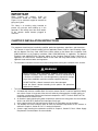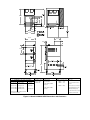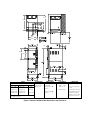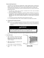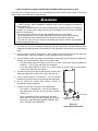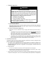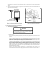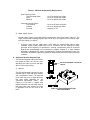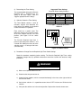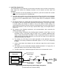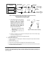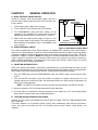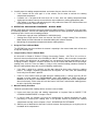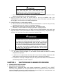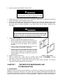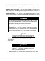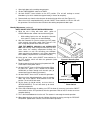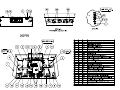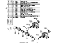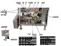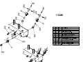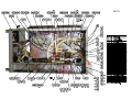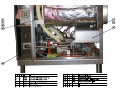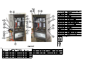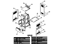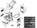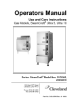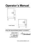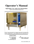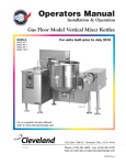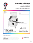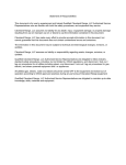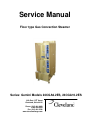
1
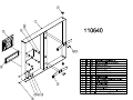
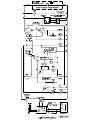
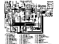
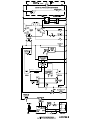
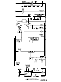
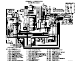
Service Manual
Floor type Gas Convection Steamer
Series: Gemini Models 24CGA6.2ES, 24CGA10.2ES
1333 East 179th Street
Cleveland, Ohio 44110
Phone: (216) 481-4900
1-800-338-2204
Fax: (216) 481-3782
www.clevelandrange.com
FOR THE INSTALLER
FOR YOUR SAFETY
Do not store or use gasoline or
other flammable vapors or
liquids in the vicinity of this or
any other appliance.
WARNING
WARNING
Improper installation, adjustment, alterations,
services or maintenance can cause property
damage, injury or death. Read the
installation, operating and maintenance
instructions thoroughly before installing or
servicing this equipment.
Disconnect power before servicing
IMPORTANT
IT IS IMPORTANT TO POST INSTRUCTIONS WHICH ARE TO BE FOLLOWED
IN THE EVENT THE USER SMELLS GAS. THESE INSTRUCTIONS SHOULD
BE LOCATED IN A PROMINENT LOCATION, AND BE FULLY UNDERSTOOD
BY ALL USERS OF THIS EQUIPMENT. THIS INFORMATION SHOULD BE
OBTAINED FROM YOUR LOCAL GAS SUPPLIER.
ALL SERVICE MUST BE PERFORMED BY A QUALIFIED CLEVELAND
RANGE AUTHORIZED TECHNICIAN.
The wiring diagram is located on the back of the lower front panel.
RETAIN THIS MANUAL FOR YOUR REFERENCE
Cleveland STATEMENT OF POLICIES
LIMITED WARRANTY
CLEVELAND RANGE products are warranted to the original purchaser to be free from defects in materials and workmanship
under normal use and service for the standard warranty period of one year from date of installation or 18 months from date of
shipment, which ever comes first.
CLEVELAND RANGE agrees to repair or replace, at its option, f.o.b. factory, any part which proves to be defective due to
defects in material or workmanship during the warranty period, providing the equipment has been unaltered, and has been
PROPERLY INSTALLED, MAINTAINED, AND OPERATED IN ACCORDANCE WITH THE CLEVELAND RANGE OWNER’S
MANUAL.
CLEVELAND RANGE agrees to pay any FACTORY AUTHORIZED EQUIPMENT SERVICE AGENCY (within the continental
United States, and Hawaii) for reasonable labor required to repair or replace, at our option, f.o.b. factory, any part which proves
to be defective due to defects in material or workmanship, during the labor warranty period. This warranty includes travel time
not to exceed two hours and mileage not to exceed 50 miles (100 miles round-trip), BUT DOES NOT INCLUDE POST STARTUP, TIGHTENING LOOSE FITTINGS, MINOR ADJUSTMENTS, MAINTENANCE, CLEANING OR DESCALING.
The standard labor warranty allows factory payment of reasonable labor required to repair or replace such defective parts.
Cleveland Range will not reimburse the expense of labor required for the repair or replacement of parts after the standard
warranty period, unless an Extended Labor Warranty Contract has been purchased to cover the equipment for the balance of the
warranty period from the date of equipment installation, start-up, or demonstration.
PROPER INSTALLATION IS THE RESPONSIBILITY OF THE DEALER, THE OWNER-USER, OR INSTALLING
CONTRACTOR, AND IS NOT COVERED BY THIS WARRANTY. Many local codes exist, and it is the responsibility of the
owner and installer to comply with these codes. Cleveland Range equipment is built to comply with applicable standards for
manufacturers, including UL, ANSI, NSF, ASME/Ntl. Bd., CSA, and others.
BOILER (Steam Generator) MAINTENANCE IS THE RESPONSIBILITY OF THE OWNER-USER AND IS NOT COVERED BY
THIS WARRANTY. The use of good quality feed water is the responsibility of the Owner-User (see Water Quality
Recommendations below). THE USE OF POOR QUALITY FEED WATER WILL VOID EQUIPMENT WARRANTIES. Boiler
maintenance supplies, including boiler hand hole gaskets, are not warranted beyond the first 90 days after the date the
equipment is placed into service. Preventive maintenance records must be available showing descaling per applicable
Cleveland Operator Manual for Boiler Proration Program considerations.
WATER QUALITY RECOMMENDATIONS
TOTAL DISSOLVED SOLIDS
TOTAL ALKALINITY
SILICA
CHLORIDE
pH FACTOR
less than 60 parts per million
less than 20 parts per million
less than 13 parts per million
less than 30 parts per million
greater than 7.5
The foregoing shall constitute the sole and exclusive remedy of original purchaser and the full liability of Cleveland Range for
any breach of warranty. THE FOREGOING IS EXCLUSIVE AND IN LIEU OF ALL OTHER WARRANTIES, WHETHER
WRITTEN, ORAL, OR IMPLIED, INCLUDING ANY WARRANTY OF PERFORMANCE, MERCHANTABILITY, OR FITNESS
FOR PURPOSE, AND SUPERSEDES AND EXCLUDES ANY ORAL WARRANTIES OR REPRESENTATIONS, OR WRITTEN
WARRANTIES OR REPRESENTATIONS, NOT EXPRESSLY DESIGNATED IN WRITING AS A “WARRANTY” OR
“GUARANTEE” OF CLEVELAND RANGE MADE OR IMPLIED IN ANY MANUAL, LITERATURE, ADVERTISING BROCHURE
OR OTHER MATERIALS.
CLEVELAND RANGE’S liability on any claim of any kind, including negligence, with respect to the goods or services covered
hereunder, shall in no case exceed the price of the goods or services, or part thereof, which gives rise to the claim. IN NO
EVENT SHALL CLEVELAND RANGE BE LIABLE FOR SPECIAL, INCIDENTAL, OR CONSEQUENTIAL DAMAGES, OR ANY
DAMAGES IN THE NATURE OF PENALTIES.
LIMITED EXTENDED WARRANTY COVERAGE
The purchase of a Limited Extended Warranty Contract extends the standard warranty coverage to the purchased period of
time (one to two years) from the date of installation, start-up, or demonstration, whichever is sooner.
*An additional two years Parts and Labor Warranty can be purchased with each piece of Cleveland equipment for an
additional 2% of the List Price per year. The 2% of list price charge will be the net invoice amount for each year of
extended warranty purchased.
-
Extended warranty must be purchased at the same time the equipment is purchased.
-
Extended Warranty has the same exclusions as stated in our standard warranty.
Second year limited extended warranty coverage on Cleveland Steamers when purchased with a water filter applies to water
related components only.
CHAPTER 1 PRODUCT IDENTIFICATION
Cleveland Range, Inc. assigns two product identification numbers to each steamer: a model number and a
serial number. The model number identifies the product characteristics. The serial number identifies the
individual unit.
A. MODEL NUMBER
This manual covers the Gemini Model No. 24CGA6.2S, 24CGA6.2SES, 24CGA10.2, and 24CGA10.2ES
Dual Steam Generator and Convection Steamer.
Each character of this model number identifies a characteristic of the steamer. The Gemini Model No.
24CGA10.2ES is 24 inches wide, a Convection steamer, Gas powered, and an Atmospheric steam
generator with a capacity for 10 cooking pans, this model has the extra suffix “.2” to differentiate it from our
standard 10 pan model that does not have two separate generators and Energy Saver for models designed
for high efficiency operation. This manual covers all standard features and options available on Gemini gas
steamers.
Model 24CGA6.2S and 24CGA10.2 are steamers designed for high capacity operation. The burners that
supply steam and the condenser spray to the compartments are on continuously while the unit is in timed
cooking mode or in the manual cooking mode. The burners and condenser spray stay on until the cooking
operation is complete.
Model 24CGA6.2SES and 24CGA10.2ES are steamers designed for high efficiency operation. The
energy saver models provide steam in a similar manner to our high capacity models except that the flow
of steam is regulated by cycling the burners off once the desired cooking temperatures is reached. When
the temperature drops to a set point below the desired cooking temperature the burners will turn back on
to bring the cooking compartment back up to temperature. The burners will continue to cycle on and off
as necessary to maintain temperature until the cooking operation is complete. The condenser spray is
activated periodically to cool the condensate water to the drain automatically through the use of a
thermostat control.
NOTE TO INSTALLER: There are some significant differences in the installation procedures between the
24CGA6.2S, 24CCG10.2 and the 24CGA6.2SES, 24CGA10.2ES units. Pay close attention to section
headings for specific installation instructions for each model listed.
B. SERIAL NUMBER
During manufacture, Gemini Steamers are
assigned individual serial numbers. Whenever
any inquiry is made with Cleveland Range
regarding a steamer the serial number should
be referenced.
C. PRODUCT INFORMATION PLATE
The Product Information Plate on the left side of
the unit lists the model and serial number of the
steamer. Figure 1-1 illustrates a typical Gemini
Product Information Plate. The rating plate also
lists power and wiring requirements.
Figure 1-1 Gemini Product Information Plates
1
D. GENERATOR VENT – IMPORTANT
IMPORTANT
When installing this steamer, under no
circumstances should the Steam Vent (See
Figure 1-2), be removed, capped or attached to
piping of any kind.
This fitting is an auxiliary safety intended to
prevent any pressure from building up in the
generator in the unlikely event the steam outlets
of the steamer should become plugged or
restricted.
CHAPTER 2 INSTALLATION INSTRUCTIONS
Figure 1-2 Generator Vent
A. GENERAL
This equipment should only be installed by qualified, professional plumbers, pipe fitters, and electricians.
•
The steamer is to be installed to comply will the applicable Federal, State or Local Plumbing Codes,
with the National Fuel Gas Code, ANSI Z223.1-(latest edition) or the Natural Gas Installation Code
CAN/CGA-B149.1 or the Propane Installation Code CAN/CGA-B149.2 as applicable, The National
Electrical Code, ANSI/NFPA No. 70-(latest edition) or the Canadian Electrical Code, CSA C22.2 as
applicable, the Food Service Sanitation Manual of the Food and Drug Administration (FDA) and all
applicable state and local codes and regulations.
•
The installation instructions must be read in their entirety before starting the installation of this steamer.
WARNING
DEATH, INJURY, AND EQUIPMENT DAMAGE could result from the
improper installation, adjustment, alteration, service or maintenance of
a steamer or installation of a unit damaged during shipment or storage.
Any of these conditions could also void the equipment warranty.
DO NOT INSTALL a Gemini steamer that has been damaged.
Install the Gemini steamer according to the policies and procedures
outlined in this manual.
•
To install this steamer, the following requirements must be considered when selecting a location.
a. A suitable drain must be available within 12 ft. of the steamer. Do NOT install the appliance directly
over a drain. Steam rising up out of the drain will adversely affect operation, hamper cooling air
circulation, and damage electrical and electronic components. NOTE: The drain MUST NOT be
located beneath the steamer itself.
b. An electrical supply matching the power requirements found on the rating plate must be available,
which is not of the GFCI (Ground Fault Interrupter Circuit) type.
c. A gas supply matching the fuel requirements found on the rating plate must be available.
d. The location must have sufficient space to meet the clearance requirements of the steamer as
outlined in Chapter 2, Section B, Part 1, “Locating the Steamer”.
e. A water supply meeting the requirements outlined in Chapter 2, Section B, Part 6 “Water Supply
Requirements and Installation” must be available.
B. INSTALLATION OF THE STEAMER
After selecting the steamer’s operating location the steamer can be positioned, and installed.
CAUTION
Malfunctions and equipment damage may result from improper
mounting. Malfunctions and/or damage resulting from improper
mounting are not covered by the equipment warranty.
The steamer MUST BE LEVEL BOTH FRONT TO BACK AND
SIDE TO SIDE in all mounting arrangements.
Catastrophic damage will result from shifting the steamer more than
o
10 out of level with power supplied to the unit.
1. Locating the Steamer
a. Location and Clearance Requirements of the Steamer
For safe and efficient operation, observe the following criteria when selecting an operating location
for the Gemini steamer.
1) The unit should be installed in an area that is free and clear of combustible materials.
2) Do NOT install the appliance directly over a drain. Steam rising up out of the drain will
adversely affect operation, hamper cooling air circulation, and damage electrical and
electronic components.
3) A proper air supply for combustion and ventilation is critical to safe, efficient operation of Gemini
gas steamers.
4) Do not install any heat producing equipment near the air vents of the equipment. Do not block
the air vents of the unit. Do not store articles on top of the unit.
WARNING
All clearance requirements above, below, and around the unit are the
same for non-combustible locations as for combustible locations.
5) Figure 2-1, 2-2, 2-3, and 2-4 illustrate the dimensions and clearances required for these
steamers. Maintain the following minimum dimensions around the unit for safe and efficient
operation, maintenance and service.
•
•
•
Maintain a 3-inch operating clearance at the sides of the unit, and at least a 3-inch
clearance at the back.
A 12 in clearance is recommended on the right side for servicing the steamer.
Approximately 24 inches of clearance is recommended in front of the unit for opening the
door and standard pan clearance.
6) The steamer must be level both front to back and side to side. Select an operating surface
that is level enough to allow leveling the unit without extreme adjustment of the legs.
7) The location selected must be capable of supporting 650 lbs. for a Gemini steamer. This
includes the weight of the water and the food.
33.13
17.43
15.06
12.76
5.00
4.87
7.75
10.44
20.63
20.88
23.37
13.25
2.06
10.00
4.75
20.36
13.88
5.00
59.21
A
A GAS
1-1/4" IPS line size, 3/4" connection
NATURAL
PROPANE
BTU
Piping 3/4" NPT
Piping 3/4" NPT.
50,000
each
Supply pressure
Supply pressure
Generator
4.50" W.C. Min. 11.00" W.C. Min.
14.00” W.C. Max. 14.00” W.C. Max.
100,000 total
B ELECTRIC
COLD WATER
115V-1Phase, 60 Hz. 35 PSI minimum
2 Fans & controls
60 psi maximum
150 watts each
(1) 1/2" dia. IPS for
Condenser
(1) 3/8" dia. IPS for
Generator
CLEARANCE
RIGHT = 12.00" for service
C DRAINAGE
2" dia. O.D.
SIDES = 3.00”
D
REAR = 3.00”
Do not connect other units to
this drain.
FRONT = 24.00”
Drain must be free air vented.
E
Manufacturer must be notified if unit will
be used above 2,000 feet
Figure 2-2 Gemini 24CGA6.2SES Dimensions and Clearances
Drain plumbing must be able
to withstand 140°F (60°C).
The drain must not be located
beneath the steamer itself.
37.13
33.13
17.43
15.06
12.76
5.00
4.00
4.87
7.75
10.44
20.63
20.88
2.06
3.38
25.56
19.19 TYP
5.00
A GAS
1-1/4" IPS line size, 3/4" connection
NATURAL
PROPANE
BTU
Piping 3/4" NPT
Piping 3/4" NPT.
50,000
each
Supply pressure
Supply pressure
Generator
4.50" W.C. Min.
14.00” W.C. Max.
11.00" W.C. Min.
14.00” W.C. Max.
100,000 total
B ELECTRIC
COLD WATER
115V-1Phase, 60 Hz. 35 PSI minimum
2 Fans & controls
60 psi maximum
150 watts each
(1) 1/2" dia. IPS for
Condenser
(1) 3/8" dia. IPS for
Generator
CLEARANCE
RIGHT = 12.00" for service
C DRAINAGE
2" dia. OD
SIDES = 3.00”
D
REAR = 3.00”
Do not connect other units to
this drain.
FRONT = 24.00”
Drain must be free air vented.
E
Manufacturer must be notified if unit will
be used above 2,000 feet
Figure 2-4 Gemini 24CGA10.2ES Dimensions and Clearances
Drain plumbing must be able
to withstand 140°F (60°C).
The drain must not be located
beneath the steamer itself.
Exhaust Hood Requirements
The Gemini gas steamer MUST be installed under a suitable ventilation hood as required by the
National Fuel Gas Code, ANSI Z223.1/NFPA 54. The venting hood system must also include an
interlock to prevent the operation of this steamer without the operation of the ventilation hood.
The exhaust hood must extend over the gas flue opening on top of the steamer and meet the
following requirements:
1). The Gemini gas steamer must be vented in accordance with all local, state and national
codes for venting gas fired appliances.
2). The exhaust hood must be sized for the cumulative ventilation requirements of all the gasfired appliances in the area including the Gemini. Figures 2-1, 2-2, 2-3 and 2-4 contains the
dimensions, gas flow, and BTU per hour data required to calculate the minimum required
hood dimensions and minimum ventilation capacity (c.f.m.) for the Gemini 6 and 10 pan
steamers.
3). Do not connect the exhaust hood directly to the flue outlet of the steamer.
4). If an existing hood cannot be used, a new one should be constructed over the steamer.
b. Positioning and Leveling the Steamer
NOTE: If there is not enough room to work on the drain, electrical, gas and water lines with the
unit in place, postpone positioning and leveling the unit until all site preparation is
completed. After the lines are prepared, position and level the steamer then connect the
utility lines.
WARNING
INJURY AND EQUIPMENT DAMAGE could result from improper lifting. A Gemini
Steamer weighs approximately 545 pounds. Use enough workers with experience
lifting heavy equipment to place the steamer on the supporting surface
Move the steamer into position. Using a level, adjust the adjustable legs until the unit is level.
2. Install Slide Racks
a. Refer to Figure 2-5. Each rack has four
loops: two at the top and two at the bottom.
Hold the slide rack so the ends of the
hanger loops are towards the cavity wall, as
shown in the figure.
b. Slide one rack into the compartment with
loops toward one side.
c.
Hook the loops over the top and bottom pins.
d. Repeat steps a. through c. for the other
racks.
Figure 2- 5 Slide
Rack Installation
3. Drain Installation for Models 24CGA6.2SES & 24CGA10.2ES (high efficiency) Only
Furnishing and installing the drain line is the responsibility of the owner and/or installer. Figure 2-7 illustrates
a drain layout recommended by Cleveland Range.
WARNING
DEATH, INJURY, AND EQUIPMENT DAMAGE could result from improper installation of
the drain outlet lines.
Improper installation of these lines could void the Gemini Steamers warranty. The following
restrictions are critical to the safety of personnel and equipment, and must not be violated
under any circumstances.
o
Do not connect the drain line into any drain material that cannot sustain 140 F.
Do not connect drains from any other equipment to the drain line of the Gemini Steamer.
Do not connect the drain outlet extension line directly to a floor drain or sewer line.
The drain line must be free air vented, have gravity flow from the steamer, and terminate
outside the perimeter of the unit.
1. The drain lines must be installed in compliance with the Food Service Sanitation Manual of the
Food and Drug Administration (FDA) and WITH THE applicable Federal State, or Local plumbing
codes.
2. Do not install the steamer directly over a drain. Steam rising up out of the drain will adversely
affect operation, cooling air ventilation and may damage electrical components.
3. The total length of pipe and number of bend fittings required to reach the open drain determines
the pipe size used to extend the drain line to an open drain.
•
•
If the drain outlet extension requires 6 feet or less of pipe, and no more than two elbows are
required, 1- ½ inch ID pipe and fittings are acceptable.
If the drain outlet extension requires 6 to 12 feet of pipe, or requires three or more elbows,
2-inch ID pipe and fittings are required.
4. The drain line must have a gravity flow from the steamer drain
outlet to the floor drain. Do not install a trap in the drain line.
5. Free air venting requires a minimum of 1 inch of clearance
between the end of the drain line and the top of the floor drain.
6. Do not connect the steamer drain directly to drains or
plumbing of any other equipment.
7. Connect the drain to the steamer as described below:
•
•
The steamer is supplied with a 2 in tube connection at
the bottom of the unit and a no-hub connector, included
(Figure 2-7).
When assembling the pipes and fittings of the drain
outlet extension, apply a hardening type pipe sealant to
the threads, and thread them together FINGER TIGHT
ONLY. DO NOT USE A WRENCH.
DRAIN
DRAIN LINE
D
1" CLEARANCE
MINIMUM
REAR DRAIN
Figure 2-7
Typical Drain Connection
4. Install Gas Supply Lines
a. Gas Supply Requirements
1) Make sure the gas supply type matches the type of gas shown on the rating plate.
2) Make sure that the gas supply pressure does not exceed 14” water column, and falls within
the acceptable gas pressure range shown below:
•
Natural gas pressure must be between 4½” – 14” water column.
•
Propane gas pressure must be between 11” – 14” water column.
b. Install Gas Supply lines
The installer/owner is responsible for furnishing and installing the gas supply lines, valves,
regulators, and accessories. When installing the gas supply lines and accessories, observe the
following:
1). The installation must conform with local codes, or in the absence of local codes, with the
National Fuel Gas Code, ANSI Z223.1 (latest edition) or the Natural Gas Installation Code,
CAN/CGA-B149.1 or the Propane Installation Code, CAN/CGA-B149.2 as applicable.
2). THE GAS SUPPLY PRESSURE TO THE
STEAMER MUST NEVER EXCEED 14”
WATER COLUMN (½ psi). If the gas supply
pressure exceeds 14” water column; a
pressure regulator must be installed in the
gas supply plumbing to reduce the pressure
to the steamer.
MAIN GAS
SUPPLY
3). Refer to Figure 2-8 for the recommended
layout of the gas supply lines. Refer to
Figure 2-1, 2-2, 2-3, or 2-4 depending on
which model you have, Detail A for the
location of the ¾ inch gas inlet of the
steamer.
4). Install a manual shut off valve between the
gas supply and the steamer. See Figure 2-8.
From now on this valve will be referred to as
the Main Manual gas valve.
5). It is recommended that a sediment trap (drip
leg) be installed in the gas supply line. See
Figure 2-8.
6). Use a pipe sealant compound, which is
resistant to LP gas.
PRESSURE REGULATING
VALVE (IF REQUIRED)
MAIN
MANUAL GAS
SHUTOFF VALVE
Gemini
DRIP LEG
GAS MANIFOLD
CONNECTION
GAS SUPPLY
CONNECTION A ON
DIMENSION DIAGRAM
Figure 2-8, Recommended
Gas Supply Line Layout
c. Testing Gas Supply Lines
WARNING
FIRE OR EXPLOSION HAZARD
LEAKING GAS CAN CAUSE FIRE OR EXPLOSION WITH PROPERTY
DAMAGE, INJURY OR LOSS OF LIFE. If the installer smells gas, or
suspects there is a gas leak, immediately refer to the posted gas leak
instructions. The posted instructions are provided by the local gas supplier,
and supersede any other instructions. Until the leak is stopped observe the
following precautions in addition to the posted instructions:
Do not light or start any appliance.
Do not touch any electrical switch.
Do not use any phone in the building.
Immediately call the gas supplier from a phone away from the building.
Follow the gas supplier’s instructions.
If the gas supplier cannot be reached call the fire department.
1). Leak Testing the appliance
Before permanently turning on gas to the steamer or after any service to the gas supply, test
all pipe joints for leaks with a soap and water solution. All leaks must be corrected before
attempting to operate the steamer.
2). Pressure Testing the Gas Supply Lines
The steamer must be isolated from the gas supply system during any pressure testing as
follows:
•
The appliance and its main manual shut-off valve must be disconnected from the gas
supply piping system during any pressure testing of the system at test pressures in
excess of 14” water column (½ psi or 3.45 kPa). Be sure to leak test all fittings with a
soap and water solution after reconnecting the gas supply.
•
The appliance must be isolated from the gas supply piping system by closing its main
manual shut-off valve during any pressure testing of the gas supply piping system at test
pressures equal to or less than 14” water column (½ psi or 3.45 kPa).
5. Install Electric Power Lines
The electrical supply must match the power requirements specified on the steamers rating plate and be
made in accordance with the following requirements.
a. The steamer must be grounded and have the electrical power lines installed in accordance with
local codes and/or the National Electric Code, ANSI/NFPA No. 70-LATEST EDITION (USA) or the
Canadian Electrical Code, CSA C22.2, as applicable. The wiring diagram is located on the back of
the lower front panel.
b. Power connection
c.
•
This unit is not suitable for connection to a GFCI (Ground fault Circuit Interrupter).
•
Cleveland Range recommends that the unit be connected to the electrical system, using a
flexible conduit system compliant with the applicable codes.
A main disconnect switch and a separate fuse or breaker should be installed near the unit as shown
in Figure 2-8. See Figure 2-1, 2-2, 2-3, or 2-4 for the steamers power requirements. Throughout the
remainder of this manual the fused disconnect switch is referred to as the main external power
switch.
d. Refer to the connection diagrams in Figure 2-10, and connect the wires to the terminal block and
ground connector accordingly.
MAIN EXTERNAL
POWER SWITCH
Gemini
ELECTRICAL CONDUIT
INLET
DRAIN LINE
GROUND
LUG
TERMINAL
BLOCK
COLD WATER SUPPLY LINES
Figure 2-9, Recommended Electrical Layout
Figure 2-10, Electrical Connections
6. Water Supply Requirements and Installation
a. Water Supply Requirements
CAUTION
Using water not within the limits specified in this
manual could void or reduce Cleveland Range’s
warranty coverage of the steamer.
1). Water Quality
As with any steam generating equipment, poor water quality degrades the performance of the
steamer.
Check the quality of supply water as described below before starting construction of the water
supply lines. If a water treatment system must be installed to achieve acceptable water quality,
install it before connecting the water supply lines to the Gemini Steamer.
If softened or chlorinated water is used in a Gemini steam generator, a carbon type filter must
be used for the water before it enters the steamer to remove Chlorine or other salts. If the water
supply is treated or softened either by the Water Company or on the premises, it may contain
chlorine or various salts. These additives are damaging to the steam generator. Salts and
chlorine used to soften or treat water cause rapid scale buildup, and/or increased corrosion if
allowed to flow into the steamer.
Contact a local water treatment specialist for an on-the-premises water analysis. The
recommended minimum feed water quality requirements for the steamer are listed in Table 2-1.
Table 2-1. Minimum Water Quality Requirements
Scale Forming Factors
Total Dissolved Solids
Silica
Alkalinity
less than 60 parts per million
less than 13 parts per million
less than 20 parts per million
Corrosion-Causing Factors:
Free Chlorine
Chloride
PH factor
less than 0.5 parts per million
less than 30 parts per million
greater than 7.5
2). Water Supply System
Provide a water supply system that fulfills the requirements of the limits listed in Table 2-1. The
2
supply must provide a minimum dynamic pressure of 35 psi (2.4 kg/cm ) and a maximum static
2
pressure of 60 psi (4.1 kg/cm ).
•
If analysis shows that the supply water is NOT within the required limits, either a water
treatment system and/or carbon filter must be installed in the line feeding the steam
generator or the frequency of maintenance, cleaning, and descaling must be increased
beyond that recommended in the maintenance schedule (Chapter 3). If more frequent
descaling is selected as the means of protecting the steamer from premature failure, the
“DESCALE REQUIRED” light timing should be readjusted to reflect the increased cleaning
schedule.
b. Setting the Descale Required Light
The Descale Required Light feature tracks
the number of hours the unit has been
operating since it was last reset, and lights
when it is time for descaling.
DESCALE REQUIRED LIGHT/RESET
SWITCH.
1). General
The Descale Required Light consists of an
indicator light, a solid state timer module,
and a reset/rocker switch. (The light and
reset switch consist of a single device on
the front panel identified by the
“DESCALE REQUIRED” label.)
See
Figure 2-11. The timer is a digital clock
module inside the unit that keeps track of
how many hours your steamer has been
in operation since the last reset of the
timer.
Figure 2-11 Descale Required Light
and Timer Module
2). Determining the Timer Setting
Suggested Timer Settings
Based on Water Quality/Hardness
The recommended setting of the Descale
Required light is determined by the
quality of the water supply. Table 2-2
suggests appropriate timer settings.
Quality of
Feed Water
Poor
Average
Good
Very Good
3). Switches Determine Timer Setting
The Timer Module contains a bank of
miniature switches that determine the
timer setting. The switches can be placed
in either the ON or OFF positions.
Hardness
(grains/gal.)✳
25
15
7
3 or less
Timer
Settings
128 hours
256 hours
384 hours
512 hours
✳17.1 ppm = 1 grain/gal of hardness
Table 2-2
ON 1 2 3 4
Each switch has a specific value. The
total timer setting is the sum of the values
of all of the switches that are in the ON
position. (See Figure 2-12 for switch
values).
128
256
512
1,024
The Descale Required Light timer is
preset at the factory with switches 1 and
2 turned ON. Adding the values of these
switches results in a setting of 384 hours
(128+256=384).
Switch
Values
(in Hours)
Figure 2-12 Switch Values
4). Procedure to Change Descale Required Light Timer Switch Settings
Read this procedure completely before starting. The Descale Required Light Timer setting
should be changed only by qualified maintenance technicians familiar with electrical safety
procedures.
WARNING
Disconnect the electrical power before servicing.
a) Make sure all power to the unit is OFF.
b) Determine the time you want to set.
c) Locate the timer modules, which are located horizontally in the front, at the right and left of
the electrical drawer.
d) Set the timer switches. It is a good idea to turn them all OFF first then turn ON the desired
switches.
e) Verify that the switches are in the desired position. Replace the electrical drawer cover.
c. Install Water Supply Lines
The installer/owner is responsible for the correct water connection of the unit. When connecting the
water supply lines observe the following instructions and all national and local codes and
regulations:
1). Never connect the unit to HOT WATER. The condenser system of the steamer will not work
properly if it is connected to HOT or WARM water.
2). The water supply should have a minimum flow pressure of 35-psi (2.4 kg/cm²) and a maximum
static pressure of 60-psi (4.1 kg/cm²). If the static pressure is above 60 psi, a pressure regulator
must be used set at approximately 50 psi. Pressure above 60 psi can damage the solenoid
valves.
3). The Gemini Steamers are supplied with two connection points for incoming water, one feeds
the condensers and the second supplies feed water to the generators. If the local water supply
is of poor quality (see Chapter 2, Section 6, Part a.1 for details of water quality), it is
recommended that treated or otherwise filtered or conditioned water be used to supply the feed
water to the generators. In the case of using a separate water supply, use the layout shown in
Figure 2-14.
4). Pay attention to the following requirements and recommendations when connecting the
steamer to the water supply:
a) Cleveland Range recommends the plumbing layout illustrated in either Figure 2-13, for
installations using a single water supply or Figure 2-14 if a separate conditioned water
supply is being used for boiler feed. Note: If using a single water feed to the system the
supply piping to the tee fitting should be of at least the next largest size of pipe to the
connection provided at the steamer.
b) The steamer has IPS fittings for the water connections to the generator and to the
condenser. These fittings are detailed as D and E in Figure 2-1, 2-2, 2-3 or 2-4, depending
on model.
c) Install a manual water valve between the main cold water supply line(s) and the steamer
supply lines.
d) This steamer must be installed with adequate backflow prevention in all supply lines, to
comply with federal, state or local codes having jurisdiction.
e) The water supply line(s) should be designed so that the unit can be moved for service.
Gemini
Condenser Solenoids
Water Connection D on
Dimension Diagram
Strainer*
Air/Water Column
(if required)
Check Valve
Main Cold
Water Supply
Steam Generator
Solenoids
Water Connection E on
Dimension Diagram
Pressure Reducer
(if required)
Figure 2-13 Cleveland Range Single Water Supply Arrangement
[*Installed internal on all Gemini models]
Main Water
Shut Off Valve
Flow
Water Connection D on
Dimension Diagram
Gemini
Strainer*
Check Valve
Air/Water Column
(if required)
Standard Cold
Water Supply Flow
Condenser Solenoids
Water Connection E on
Dimension Diagram
Pressure Reducer
(if required)
Steam Generator
Solenoids
Main Water
Shut Off Valve
Conditioned Cold Flow
Water Supply
Figure 2-14 Cleveland Range Single Water Supply Arrangement when Using
Separate Conditioned Feed Water Supply
[*Installed internal on all Gemini models]
f)
A 40 or 50-mesh water strainer (dirt filter)
of one of the types and construction
illustrated in Figure 2-15, Cleveland
Range part number 106684 or 19870 is
supplied with the unit and should be
installed where indicated in the plumbing
layout. Note: On some Models the
strainer has already been installed as
part of the internal water piping.
•
•
Make sure the arrow on the strainer
body points in the direction of flow
into the steamer.
Install the strainer so the access nut
points down.
P/N 106684
P/N 19870
Figure 2-15 Water Strainer Assembly
g) Construct all supply lines up to the point of installing the strainer. Flush the water supply
lines before connecting the strainer.
h) Apply pipe dope or Teflon tape to any threaded connection.
d. Testing Water Supply Lines
1). Check all connections for proper tightness. Remove the side panel to inspect water connections
inside the steamer.
2). Open the water supply valves.
3). Check all lines and connections for leakage, both inside and outside the steamer.
4). If Startup and Checkout will be performed next, leave the right side panel off; otherwise, replace
the side panel and secure it to the unit.
C. STARTUP AND CHECKOUT
The Startup and Checkout procedure prepares a recently installed or repaired steamer for operation. The
procedures check proper electrical, gas, water, and drain connections to the steamer, and verify basic
steamer operation.
1. Installation Checkout
Use the Installation Checklist Table 2-3, to check the overall installation.
Table 2-3. Installation Check List
TASK
Preparation
Verify Electric Power Requirements
Verify Gas Supply Requirements
Verify Exhaust Hood Requirements
Test supply water quality
Check operating location clearances
Installation
Verify steamer is level
Check drain line connection
Check Exhaust Hood
Check electrical line connection
Check water supply connection
Test water supply lines
Check Gas Supply Connection
Leak Test Gas Supply Connection
Check Burner Ignition Test
Perform Startup and checkout
Notes on installation:
REFERENCE
Page No.
Rating Plate
11
8
13
3
8
9
8
12
16
17
11
12
19
20
COMPLETED
CHAPTER 3
GENERAL OPERATION
A. MAIN EXTERNAL POWER SWITCH
Usually the steamers main external power switch is left ON. If
the main external power switch was left in the OFF position, turn
it ON as follows.
MAIN EXTERNAL
POWER SWITCH
1. Check that the water supply valves are open.
Gemini
2. Turn the ON/OFF levers/switches to the OFF position.
3. The TIMED/MANUAL switch and timer settings are not
important in this procedure. The control panel circuits are
not powered while the ON/OFF levers/switch is set to OFF.
4. Refer to the main external power switch in Figure 3-1, and
turn on electric power to the steamer. The steam generators
will immediately start blowdown cycles. The blowdown cycle
lasts 3 minutes.
DRAIN LINE
COLD WATER SUPPLY LINES
B. DOOR INTERLOCK SWITCH
Figure 3-1 Main External Power Switch
The steamer compartments of the Gemini Steamer are equipped with automatic steam cutoff switches,
which turn OFF the production of steam to a cooking compartment whenever the door to that compartment
is opened. In addition the action of opening the doors resets the 60 minute Energy Conservation - Idle Timer
Described in Chapter 2, Section H. NOTE: Even though the continued production of steam ends as soon as
a door is opened, it may take up to a minute for residual steam in the system to clear from the steam lines
and the cooking compartment. To avoid possible injury always wait until this residual steam has cleared
before reaching into the cooking compartment.
C. POWER ON (AUTOMATIC FILL)
When each steamer compartment is turned ON, it automatically fills its steam generator with water. Use this
procedure at the beginning of a shift to prepare the steamer for operation without starting steam generation.
When ready to start steam cooking, begin either the Timed or Manual Operating Procedure.
1. Press the TIMED (top) end of the TIMED/MANUAL switch (for ON/OFF models set the selector switch
to OFF.
2. Turn the ON/OFF lever/switch to the ON position to energize the steamer control panel. The red
indicator light on the control panel lights, the combustion blower turns ON to purge the generator and
water fills the steam generator.
NOTE: The ON/OFF lever/switch must be turned fully to the ON position to START the steamer.
3. When the generator is full, the steamer automatically stops water flow.
4. Once the water has reached the minimum operating level, the blower turns OFF and the pilot/standby
burner lights to heat the water to the standby temperature.
D. LIGHTING AND SHUTDOWN INSTRUCTIONS
DO NOT TRY TO LIGHT THE BURNERS OR PILOT WITH A FLAME. THE PILOT AND BURNERS ARE
SELF IGNITING.
The Gemini Steamer has an electronic ignition system, which automatically lights the pilot and burners,
senses the flame and controls gas flow. This provides precise burner control, safety ignition, and
shutdown.
WARNING
DEATH, INJURY OR EQUIPMENT DAMAGE may result from an
improperly adjusted gas control and ignition system. Do not alter any
adjustments on this electronic control or gas valve.
If adjustment is required, contact an authorized service center. Cleveland
Range is in no way responsible for the operation or safety of this
equipment if the controller, valve, or igniter probe are adjusted by anyone
other than a Cleveland Range authorized service representative.
The following START-UP SUMMARY is for quick reference ONLY. For safe operation and use of this
equipment, the operators should comply with all safety and operating instructions in this manual.
Lighting Instructions
1. Turn the ON/OFF lever/switch to the ON position.
•
Blower will start and boiler will fill with water (about 3 minutes).
•
Pilot will attempt to light for 90 seconds.
•
If no ignition occurs the system will automatically reset in 6-7 minutes.
2. System may be reset manually by turning the ON/OFF lever/switch to the OFF position for 5 minutes
and then back to ON.
3. Turn ON a cooking compartment.
4. Blower will start and main burner will light.
5. Each compartment has its own control system, and must be started independently.
Shutdown Instructions
Turn the ON/OFF lever/switch to the OFF position. The burners and pilots will immediately be
extinguished and the unit will begin the automatic 3-minute blowdown cycle and drain. NOTE: Each
compartment has its own control system, and must be shut off independently.
E. INSPECTING THE COOKING COMPARTMENT
At the back of the cooking compartment, a drain screen covers the drain (Refer to Figure3-2). The screen
prevents large food particles from entering and blocking the drain line. Any blockage of the drain line or
screen can reduce drainage from the cooking compartment resulting in reduced cooking performance,
equipment damage, and a hazard to the operator. A blocked or slow drain may cause:
•
Hot water to collect in the compartment and
spill out when the compartment door opens.
•
Pressure fluctuations in the compartment,
resulting in steam leaks around the door
gasket, or compartment implosion.
•
Reduced convection in the compartment,
reducing cooking performance.
DRAIN SCREEN
Figure 3-2 Compartment
Drain Screen
CAUTION
Steam leaks around the door, cooking compartment flooding,
reduced cooking performance, and compartment implosion
can be caused by a blocked drain or drain screen. Inspect and
clean the drain and drain screen before each use.
Before every steaming operation, inspect the cooking compartment and remove any food scraps or debris
from the racks, walls, and floor of the compartment. Pay particular attention to the drain and drain screen.
1. DO NOT USE the steamer if water stands in the drain opening. Arrangements must be made
immediately to clean the drain in accordance with the instructions found in the Preventative
Maintenance and Troubleshooting section of this manual.
2. Remove any food or debris that is blocking the drain or screen.
3. Be sure the screen covers the drain. The screen prevents large pieces of food from entering and
blocking the drain.
F. PREHEATING THE STEAMER
Preheating the steamers can help insure that the best productivity and consistent cooking is obtained. To
preheat each steamer, run a cooking cycle of approximately 15 minutes with no food in the cooking
compartments.
NOTE: If using a steamer with a timer, set only a 1 minute cooking time for the purpose of preheating, since
the timer will only begin to countdown once the steamer has reached a cooking temperature.
•
BEFORE PREHEATING, inspect and clean the compartment. After preheating, the
compartment will be too hot to inspect and clean safely.
G. DESCALING REQUIRED LIGHT FEATURE
When the programmed number of hours have elapsed, the “DESCALE REQUIRED”
light will turn on, indicating that descaling of the steam generator must be done (See
Figure 3-3). More information on this feature and the descaling procedure can be
found in the Maintenance section of this manual, Chapter 6, Part A (4),
Monthly/Weekly Maintenance.
Figure 3-3 Descaling Required Light
H. ENERGY CONSERVATION FEATURES
A.
IDLE TIMER - ALL MODELS
In order to conserve energy during long periods of equipment “idleness”, this steamer is equipped with a 60minute idle timer to help conserve both water and energy and increase equipment life. The idle timer will
automatically, shut the burner system down when a cooking compartment is left on (ON/OFF Models), or
left in manual mode (timed models) for more than one hour without changing the operating mode or opening
the door.
This one hour timer is reset whenever the unit is switched to timed
(or switched OFF) and back to Manual mode (or back ON)
depending on the steamer control type, or whenever the door is
opened. As usage of the steamer will frequently reset this timing
function during normal usage, it should generally function only
when equipment has been left ON and unattended for long periods
between shifts, or if exceedingly long cook times are required. In
the later case, operating personnel will need to be aware of this
feature, so that the timer can be reset by opening and closing the
door during such prolonged cook periods.
Red
Indicator
Light.
Figure 3-4 Manual Mode Indicator Light
On models equipped with a timer, the red indicator (see Figure 3-4) in the manual side of the
TIMED/MANUAL selector switch will go out when the idle timer disrupts power to the heating circuit. This
indicator will be lit whenever the unit is in MANUAL mode and is cooking normally.
B. HIGH EFFICIENCY UNITS - “ES” MODELS
Model 24CGA6.2SES and 24CGA10.2ES are steamers designed for high efficiency operation. The
energy saver models provide steam in a similar manner to our high capacity models except that the flow
of steam is regulated by cycling the burners off once the desired cooking temperatures is reached. When
the temperature drops to a set point below the desired cooking temperature the burners will turn back on
to bring the cooking compartment back up to temperature. The burners will continue to cycle on and off
as necessary to maintain temperature until the cooking operation is complete.
CHAPTER 4
CONTROL PANELS
The standard dial timer control panel (illustrated in Figure 4-1) has a mechanical timer. An optional
electronic keypad timer, illustrated in Figure 3-2, and an ON/OFF control panel (not illustrated) are also
available. The Electronic and mechanical timers use a temperature compensation circuit, which allows the
timer to count down only while the cooking compartment is at cooking temperature. The ON/OFF Control
Panel, which is not illustrated, operates exactly like the timed models in manual mode, except a selector
switch is used to turn the steam to the cooking compartments ON and OFF.
A. DIAL TIMER CONTROL PANEL
1. Cooking Operations – Dial Timer Control Panel
For safe, efficient operation of the steamer, the operator must, at a minimum, comply with all cautions,
warnings and instructions in the detailed operating procedures and be familiar with the control panel shown
in Figure 3-1. The operator must be familiar with all the operating features explained in this manual before
attempting to operate the steamer.
2. Manual and Timed Modes
The steamer has two operating modes: manual and timed. The TIMED/MANUAL rocker switch selects the
operating mode. Pressing the MANUAL end of the switch selects the manual operating mode. Pressing the
TIMED end of the switch selects the timed operating mode. Cooking procedures are slightly different for
each mode.
a. Manual Mode
The manual mode provides continuous cooking. The operator starts and stops steaming operations
manually. See the Operating and Cooking Procedure – Manual mode in Chapter 4, Part B for more
information. A thermostat controlled pause light located on each control indicates that the cooking
compartment has not yet reached cooking temperature.
Note: These units are equipped with an energy saver timer, that will automatically, shut the
burner system down when a cooking compartment is left ON (ON/OFF Models), or left in
MANUAL mode (TIMED models) for more than one hour. This one hour timer is reset whenever
the unit is switched to TIMED (or switched OFF) and back to MANUAL mode (or back ON)
depending on the steamer control type, or whenever the door is opened. As usage of the steamer
will frequently reset this timing function during normal usage, it should generally function only
when equipment has been left steaming (ON) and unattended for long periods between shifts, or
if exceedingly long cook times are required. In the later case, operating personnel will need to be
aware of this feature, so that the timer can be reset by opening and closing the door during such
prolonged cook periods. On models equipped with a timer, the red indicator in the manual side of
the TIMED/MANUAL selector switch will go out when the idle timer disrupts power to the heating
circuit.
1). SURECOOK Indicator Light
This light is lit whenever the cooking compartment has not yet
reached cooking temperature. Note: when in the timed mode
the timer will not count down as long as this light is ON.
2). TIMER
This dial timer sets the operating time from 0 to 60 minutes.
Turn the dial clockwise until it points to the required number of
minutes. When it reaches 0, a buzzer sounds for 3 seconds.
3). TIMED/MANUAL Switch
The TIMED/MANUAL switch selects the manual or timed
operating mode.
• Pressing the MANUAL end of the switch selects the
manual mode, and lights the red indicator built into the
manual end of the switch. (See also the Note at the top of
this page)
• Pressing the TIMED end of the switch selects the timed
mode.
4). Power on Indicator Light
When the Red indicator light is on, power is on to the control
panel.
5). Descale Indicator Light Switch (not shown)
When the Amber light in the switch lights, it is time to descale
the steam generators. Pressing the switch turns off the light
and resets the internal timer which tracks steam generator
operation.
FIGURE 4-1, DIAL TIMER CONTROL PANEL
b. Timed Mode
•
The timer provides timed control of steaming operations. The timer starts and stops steaming
operations.
•
The mechanical timer control uses a temperature compensation circuit that affects only the
timer. When operating, the timer ONLY COUNTS DOWN WHILE THE COOKING
COMPARTMENT IS AT COOKING TEMPERATURE. This provides totally automatic control of
the steaming operation and assures uniform cooking as the timer automatically compensates
for food product defrosting and/or compartment heat up time. Whenever the steamer is not at
cooking temperature, the timer pauses and the PAUSE light is illuminated.
•
To use the timer, simply set the timer to the desired time. The steamer will begin cooking as
soon as the timer is set. When the timer reaches zero the steaming functions will automatically
end and a buzzer will sound for 3 seconds to alert the operator that cooking is complete.
•
Note the mechanical timer will not function when the Timed/Manual switch is set to Manual,
although the SURECOOK light will still illuminate to indicate that the cooking compartment is
not yet at cooking temperature.
B. KEYPAD TIMER CONTROL PANEL
1. Cooking Operations – Keypad Timer Control Panel
For safe, efficient operation of the steamer, the operator must, at a minimum, comply with all cautions,
warnings and instructions in the detailed operating procedures and be familiar with the control panel
shown in Figure 4-2. The operator must be familiar with all the operating features explained in this
manual before attempting to operate the steamer.
2. Manual and Timed Modes
The steamer has two operating modes: manual and timed. The TIMED/MANUAL rocker switch selects
the operating mode. Pressing the MANUAL end of the switch selects the manual-operating mode.
Pressing the TIMED end of the switch selects the timed (automatic) operating mode.
a. Manual Mode
The manual mode provides continuous steaming. The operator starts and stops steaming
operations manually. See the Operating and Cooking Procedure – Manual Mode in Chapter 4, Part
B for more information.
b. Timed Mode and Use of the Timer
1). Timer Use and Temperature Compensation
• The keypad timer control starts and stops steaming operation, and monitors cooking time
and compartment temperature for accurate, efficient, uniform steam cooking.
• The keypad control uses a temperature compensation circuit that effects only the timer.
When operating, the timer ONLY COUNTS DOWN WHILE THE COOKING
COMPARTMENT IS AT COOKING TEMPERATURE. This provides totally automatic
control of the steaming operation and assures uniform cooking as the timer automatically
compensates for food product defrosting and/or compartment heat up time. Whenever the
steamer is not at cooking temperature, the timer pauses and the display shows “PAUS”.
Once temperature is reached, a digital display of the remaining time is displayed. When the
timer counts down to zero a buzzer will sound, to indicate that cooking is complete and the
steam generator will shut down.
• The timer will operate similarly when the steamer is being operated in the manual mode
including counting down only when the steamer is at cooking temperature, except that the
timer does not start or stop the steaming cycle.
CAUTION
Press keypad with fingertips only. Do not use kitchen
utensils or anything sharp to operate the keypad.
TIMER Display
This four-digit display indicates the minutes and seconds remaining in the
count down. The display reads from zero (00:00) to 99 minutes and 99
seconds (99:99). It reads pause (PAUS) when the count down is halted
either by the START/STOP key or by the temperature compensating
circuit.
1). Number Pad Keys
These keys set the number of minutes and seconds in the timer count
down. Pressing the number keys 1 2 3 4 in this sequence, sets the timer
for 12 minutes and 34 seconds (12:34).
2). START/STOP Key
This key starts and stops the timer. In TIMED mode the steaming
functions are linked to the timer. In MANUAL mode, the steaming
functions are independent of the timer.
3). CLEAR Key
This key resets the timer to zero (00:00) after it has been stopped. The
timer must be zeroed by pressing this key before a new time can be set.
4). TIMED/MANUAL Switch
The TIMED/MANUAL switch selects the manual or timed operating mode.
• Pressing the MANUAL end of the switch selects the manual mode,
and lights the red indicator built into the manual end of the switch.
(See also the Note at the bottom of this page)
•
Pressing the TIMED end of the switch selects the timed mode.
5). Power on Indicator Light
When the Red indicator light is ON, power is ON to the control panel.
6). Descale Indicator Light Switch (not shown)
When the Amber light in the switch lights, it is time to descale the steam
generators. Pressing the switch turns off the light and resets the internal
timer which tracks steam generator operation. (See Chapter 6, Part A)
Note: Control panel for
Gemini 10 Shown
FIGURE 4-2, KEYPAD TIMER CONTROL PANEL
Note: These units are equipped with an energy saver timer, that will automatically, shut the
burner system down when a cooking compartment is left ON (ON/OFF Models), or left in
MANUAL mode (TIMED models) for more than one hour. This one hour timer is reset whenever
the unit is switched to TIMED (or switched OFF) and back to MANUAL mode (or back ON)
depending on the steamer control type, or whenever the door is opened. As usage of the steamer
will frequently reset this timing function during normal usage, it should generally function only
when equipment has been left steaming (ON) and unattended for long periods between shifts, or
if exceedingly long cook times are required. In the later case, operating personnel will need to be
aware of this feature, so that the timer can be reset by opening and closing the door during such
prolonged cook periods. On models equipped with a timer, the red indicator in the manual side of
the TIMED/MANUAL selector switch will go out when the idle timer disrupts power to the heating
circuit.
Timer Operation
a) Setting the Timer
To set the cooking time, the timer must first be zeroed by pressing the clear key. The timer
can be set only when the cooking time display is clear (00:00). The cooking time display
contains four digits. The left two digits are minutes, and the right two digits are seconds.
The display 12:34 is set for 12 minutes and 34 seconds. To set the cooking time:
(1) Change the required cooking time to minutes and seconds.
(2) Press the number keys for minutes, and then, for the seconds.
(3) If the cooking time is 99 seconds or less, only press the number keys for seconds.
b) Starting/Stopping the Timer
Press the START/STOP key to start or stop the timer. When the START/STOP key is
pressed, the steam generator begins heating the water to steam. Shortly, steam fills the
cooking compartment.
(1) The timer display reads “PAUS” until the cooking compartment reaches proper cooking
temperature, or when the timer cycle is paused by pressing the START/STOP key
again after the timer has started.
(2) When the cooking compartment reaches proper cooking temperature, the timer display
shows the count down.
NOTE:
A timer setting of 10 minutes may in fact take 11 or 12 minutes for the timer to
count down and the alarm to sound. This is normal. Heating the compartment
and food to cooking temperature uses the additional time.
c) Shutting Off Buzzer AFTER Timer has Reached Zero
When the timer counts down to zero, the buzzer sounds continuously, the generator stops
steaming, and steam flow to the cooking compartment gradually stops.
Press the START/STOP key to silence the buzzer. The cooking time display returns to the
last time set. Either run this same setting again or clear and reset the timer.
CAUTION
Press keypad with fingertips only. Do not use kitchen
utensils or anything sharp to operate the keypad.
CHAPTER 5
COOKING WITH THE STEAMER
WARNING
When checking inside the steamer always open the door slowly
and stand to the side and back away from the steamer. Water
leaking from the door gasket can be a sign of a blocked drain. If
the drain is blocked, hot water can accumulate inside the
compartment and spill out when the door is opened.
OPERATING AND COOKING PROCEDURE – TIMED MODE
WARNING
Even though the production of steam ends as soon as a
door is opened, it may take up to a minute for residual
steam in the system to clear from the steam lines and the
cooking compartment. To avoid possible injury always
wait until this residual steam has cleared before reaching
into the cooking compartment.
In timed mode, the timer starts and stops the steaming operation.
1. Inspect and clean the drain and cooking compartment as required. Refer to INSPECT THE COOKING
COMPARTMENT IN Chapter 3 Part E.
2. If necessary, preheat the cooking compartment. Refer to PREHEATING THE STEAMER, in Chapter 3,
Part F.
3. Slide the pans of food into the slide racks inside the steamer. Do not place pans or anything else on the
bottom of the compartment.
CAUTION
Some foods drip juices. Use a solid catch pan under
perforated pans when steaming food that will drip juices.
Failure to use a catch pan can cause a clogged drain.
•
4.
5.
6.
7.
For best cooking results, use shallow, 2-1/2 inch deep, perforated pans without covers. These give
the best heat transfer and shortest cooking time.
Close the steamer door.
Check the control settings. At this point the settings should be:
• The ON/OFF lever/switch is in the ON position.
• The TIMED/MANUAL switch is in the TIMED position.
Set the required cooking time. For KEYPAD MODELS press the START/STOP key to start the cooking
cycle. Shortly after the door is closed, steam fills the cooking compartment.
When the timer reaches zero, a buzzer will sound, the steam generator stops steaming, and steam flow
to the cooking compartment gradually stops. The cooking cycle is complete.
• For DIAL timers the buzzer will stop after 3 seconds.
• For KEYPAD timers, press the START/STOP key to silence the alarm.
WARNING
SEVERE BURNS may result from exposure to steam.
Do not open the steamer door before steam flow stops. Stand back
when opening the compartment door. Open the door slightly to allow
steam to vent before looking or reaching into cooking compartment.
Do not reach into cooking compartment until the steam has cleared.
Do not reach into steamer or handle hot items without wearing
heatproof gloves. Wet or damp gloves conduct heat, and may cause
burns when touching hot items.
1
8. Carefully open the cooking compartment door, and remove the pans from the slide racks.
• If the steamer will be used again in a few minutes shut the door to maintain the cooking
compartment temperature.
• If another use is not planned for more than half an hour, leave the cooking compartment door
slightly open to reduce internal pressure while the steam condenses and the compartment cools.
• If the steamer is not being used again during this shift, perform the Power OFF and Shut Down and
Cleaning Procedures, found in Chapter 5.
A. OPERATING AND COOKING PROCEDURE – MANUAL MODE
Manual mode allows the operator to personally control the cooking functions. The operator starts and stops
the steaming operations, and sets the cooking time including time for steam generator, compartment and
food heat-up time. Use the manual-cooking mode for:
• A continuous supply of steam (24CGA6.2S & 24CGA10.2 only).
• Cooking times longer than the timer can measure. See Part 2, “Longer Cooking Times in Manual
Mode” below, for more information on extended cooking with a Gemini Steamer.
• Maintaining the compartment temperature between cooking batches.
1. Using the Timer in Manual Mode
The KEYPAD timer may be used when the steamer is operating in the manual mode, but it will not start
or stop the steaming cycle.
2. Longer Cooking Times in Manual Mode
As discussed In Chapter 3, Section H “Energy Conservation Feature – Idle Timer”, this unit has a
timer built into the manual mode or the ON Mode (for ON/OFF Models), which interrupts the operation
of the steamer after 60 minutes of “unattended” use (no opening of steamer compartment, and no
changing of modes). However, A Gemini Steamer can still be used to cook foods that require longer
cooking times, than the Timer can address, simply use the standard cooking procedure outlined for
Manual Cooking below along with any of the following modifications:
•
If the food is going to be checked, and the door opened at least hourly during the cooking
process, no change is operating procedure will be required. The “idle” timer, will automatically
reset every time the door is opened.
•
If there is not a need to check the food during the cooking process, it will be necessary for the
operator, to either switch the TIMED/MANUAL switch from MANUAL to TIMED and back to
MANUAL (or for ON/OFF Control Models, OFF and back ON) or open and close the compartment
door at least hourly. Either action will reset the internal “idle” timer, and allow the cooking process
to not be significantly interrupted.
3. Manual Cooking Procedure
Follow this procedure when cooking with the steamer in manual mode.
1) Inspect and clean the drain and cooking compartment as required. Refer to INSPECT THE
COOKING COMPARTMENT in Chapter 3 Part E.
2) In manual mode, the operator can bring the compartment to cooking temperature by either
preheating or increasing the cooking time. If the operator chooses to preheat the cooking
compartment manually, refer to Chapter 3, Part F, PREHEATING THE STEAMER.
3) Slide the pans of food into the slide racks inside the steamer. Do not place pans or anything else on
the bottom of the compartment.
CAUTION
Some foods drip juices. Use a solid catch pan under
perforated pans when steaming food that will drip juices.
Failure to use a catch pan can cause a clogged drain.
•
For best cooking results, use shallow, 2-1/2 inch deep, perforated pans without covers. These
give the best heat transfer and shortest cooking time.
4) Close the steamer door. Select the manual mode by pressing the MANUAL end of the
TIMED/MANUAL rocker switch. The steaming cycle starts as soon as the switch is pressed. Shortly
after the door is closed, steam fills the cooking compartment.
5) If the KEYPAD timer is used to monitor cooking.
a) Set and start the timer. (Remember that when the KEYPAD timer is used in this way it will only
count down time when the steamer is at cooking temperature.)
b) When the timer reaches zero, the buzzer will sound, and cooking is done.
Remember, in manual mode, the timer does not stop the steaming functions.
6) To stop manual mode steaming, press the TIMED end of the TIMED/MANUAL rocker switch and
verify that the timer is OFF (timer electronic models) or at zero (Dial timers). The generator stops
steaming, and steam flow to the cooking compartment gradually stops.
WARNING
SEVERE BURNS may result from exposure to steam.
Do not open the steamer door before steam flow stops. Stand back
when opening the compartment door. Open the door slightly to allow
steam to vent before looking or reaching into cooking compartment.
Do not reach into cooking compartment until the steam has cleared.
Do not reach into steamer or handle hot items without wearing
heatproof gloves. Wet or damp gloves conduct heat, and may cause
burns when touching hot items.
7) Carefully open the cooking compartment door, and remove the pans from the slide racks.
•
If the steamer will be used again in a few minutes shut the door to maintain the cooking
compartment temperature.
•
If another use is not planned for more than half an hour, leave the cooking compartment door
slightly open to reduce internal pressure while the steam is condensing and cooling.
•
If the steamer is not being used again during this shift, perform the Power OFF and Shut Down
and Cleaning Procedures, found in Chapter 6
CHAPTER 6
SHUTDOWN AND CLEANING PROCEDURES
A. STEAM GENERATOR BLOWDOWN
1. Power Off (Automatic Blowdown)
Blowdown occurs automatically when each steamer compartment is turned OFF at its ON/OFF
lever/switch. During blowdown, the steam generator drain valve is rinsed with fresh water, and the boiler
is drained. Blowdown at frequent intervals helps decrease mineral buildup in the steam generators, and
reduces the frequency of descaling and other maintenance.
2. Blowdown Frequency
The supply water quality determines how often blowdown must be performed. The more the steamer is
used and the higher the content of total dissolved solids and particulates in the feed water, the more
frequently blowdown must be performed. A determination should be made at the time of installation
whether additional blowdown frequency will be required as part of the daily maintenance based on the
water quality analysis done as part of the installation. This information should be noted in the daily
maintenance program developed for the equipment. After it has been determined whether the local
water supply meets the minimum supply water quality standards, observe the following guidelines to
establish proper blowdown scheduling.
• When using a supply water system that does not meet the minimum supply water quality standards,
blowdown must be performed after every 4 hours of operation and at the end of each shift.
• For units using water that meets the minimum supply water quality standard, whether naturally or by
using a water treatment system, blowdown must be performed at the end of each shift.
3. Blowdown Procedure
When each steamer is turned OFF, its blowdown cycle starts and runs automatically. The complete
cycle takes approximately 3 minutes.
(1) Turn the ON/OFF lever/switch to the OFF position to turn OFF the steamer. The red indicator light
turns OFF and the drain valve is opened. Do not turn power OFF at the main external power switch
during blowdown.
(2) The drain valve begins to draw water from the steam generator.
(3) The fill valve operates for 3 minutes to help flush any debris through the drain valve as the
generator drains.
(4) At the end of the 3-minute blowdown cycle, the fill valve closes.
(5) When blowdown is complete, the steamer can be restarted, or the shut down procedure completed.
• To restart the unit, refer to POWER ON (AUTOMATIC FILL) in Chapter 2, Part C.
• To shut down the unit, refer to SHUT DOWN AND CLEANING, below.
NOTE:
The ON/OFF lever/switch must be turned fully to the OFF position to properly START the
automatic blowdown of the steamer.
B. SHUT DOWN AND CLEANING
This procedure should be performed at the end of each day or shift.
WARNING
Do not use a hose or water jet to clean this appliance
1. Refer to Power OFF (Automatic Blowdown), and turn off the steamer compartment. Allow 3 minutes for
the complete blowdown cycle.
WARNING
SEVERE BURNS may result from exposure to steam.
Do not open the steamer door before steam flow stops. Stand back when opening
the compartment door. Open the door slightly to allow steam to vent before looking
or reaching into cooking compartment. Do not reach into cooking compartment until
the steam has cleared.
Do not reach into steamer or handle hot items without wearing heatproof gloves. Wet
or damp gloves conduct heat, and may cause burns when touching hot items.
2. Open the steamer door and allow steamer to cool.
WARNING
Inside of steamer stays hot for a long time. Be careful
when cleaning inside steamer compartment.
3. Remove the slide racks. Wash and rinse racks separately or clean them in a dishwasher according to
health requirements. Do not remove the drain screen.
4. Remove any spilled food from inside compartment and clear any residue from the drain screen. Clean
the interior of the compartment thoroughly. Use a soft bristle brush to remove stubborn food particles.
Do not use abrasive cleaning compounds or steel wool. Rinse inside of steamer compartment with
clean water.
WARNING
Let rinse water drain through compartment drain opening. If water does
not drain freely, drain lines must be cleaned before cooking again.
Clogged or slow drains are dangerous because hot water can collect in
compartment and spill out when opening compartment door.
5. Clean the door assembly.
• Remove the door gasket assembly (see Figure 6-1).
•
Note the keyhole slots on the door and the retaining pins
on the gasket assembly. Grasp the gasket assembly at
the sides and lift up and towards you to remove the
assembly.
•
Clean all surfaces of the gasket assembly, as well as the
inside of the door, by wiping with a damp cloth.
•
Rotate the gasket assembly 180° and replace it by sliding
the retaining pins into the keyhole slots. Either long edge
of the gasket assembly can be positioned at the top.
Periodic rotating of the door assembly will increase the
door gasket life.
Figure 6-1 Door Gasket
6. Replace the cleaned slide racks.
7. Wipe the exterior with a damp cloth only. NEVER HOSE DOWN THE Assembly
STEAMER. Electrical
components inside the unit will not function correctly if wet or damp.
8. After cleaning, leave the steamer door open until the next steamer operation. This prevents
compartment odor buildup and increases gasket life.
CHAPTER 7
PREVENTATIVE MAINTENANCE AND
TROUBLESHOOTING
A. MAINTENANCE
Maintenance on the steamer must be performed on a regular basis to keep the unit running properly. By
following the maintenance instructions in this chapter and in the separate Installation Manual, problems with
the steamer will be kept to a minimum. As with any preventative maintenance schedule, the frequency of
steamer maintenance may need to be increased, depending on equipment usage and water quality. If
problems do occur, refer to the Troubleshooting Guide in this chapter. For more information on products and
services, contact your sales representative.
1. Maintenance Records
Make a file solely for maintenance records. Keep a written record of daily, weekly, monthly, and yearly
maintenance. These records will protect warranty coverage, help personnel to know when to perform
various maintenance procedures, and assist service personnel.
2. Daily Maintenance
a. Blowdown Steam Generator
Blowdown each steam generator according to the steam generator blowdown instructions in
Chapter 6.
b. Clean the Steamer
Clean interior and exterior of the steamer according to the shutdown instructions in Chapter 6.
3. Weekly Maintenance
Clean Drain
CAUTION
Steam leaks, pressure buildup in the cooking compartment and poor
steaming performance can be caused by a blocked drain line or screen.
Blocked or slow drains are dangerous because hot water can collect in the
compartment and spill out when opening the compartment door.
This steamer is equipped with a drain screen in the back of each cooking compartment. Never operate the
steamer without the screens in place. The screen prevents large food particles from entering and blocking
the drain line. Any blockage of the drain line can cause a pressure buildup in the compartment, resulting in
steam leaks around the door gasket. Drain line blockage also adversely affects convection action of the
steam in the compartment, which is necessary for optimum performance.
a. Inspect the drain screen and drain line for blockage. Rotate the drain screen 90 degrees to
inspect the drain opening. Clean the opening and restore the screen to its operating position.
b. Clean drain with a USDA approved drain cleaner, once a week. Follow the instructions of the
manufacturer of the cleaner.
c. Flush drain with clean water.
4. Monthly Maintenance
Descale Steam Generator
Steam generators should be descaled at least once a month, depending on scale buildup. If you have
serious steam generator scale buildup, a water treatment system should be installed for the steamer or if
this is not possible the frequency of descaling should be increased. This unit is equipped with a Descaling
reminder light to assist in the scheduling of this maintenance. (Note: the descaling light has been factory set
for an operating time of approximately 1 month, if a different descaling frequency is required it will be
necessary to have the descaling timer reset to reflect this schedule by a qualified service technician). When
this light comes on arrangements should be made to descale the steam generator as soon as feasible.
Cleveland Range, recommends the use of DISSOLVE® Descaler Solution, Cleveland Range Part No.
106174. No other system of steamer descaling should be used.
NOTE: Part No. 106174 is the Part No. for a case (6 1-gallon containers) of DISSOLVE® descaler. It is also
available in 5-gallon containers as Part No. 1061741.
THESE INSTRUCTIONS ARE FOR USE WITH DISSOLVE® DESCALER SOLUTION Cleveland Range
Part Nos. 106174 or 1061741 ONLY.
•
Health Hazard Data, Effects of Overexposure – This product may cause a burning sensation to eyes
or skin.
•
Emergency and First Aid Procedures - In case of eye contact, immediately flush eyes with plenty of
water. If irritation persists seek medical attention. In case of skin contact, wash with soap and water. If
inhaled, remove to fresh air and if burning persists, call a physician. If swallowed, drink 1 or 2 glasses of
water and call a physician.
•
Spill or Leak Procedures – Rinse with plenty of water to dilute. Sodium carbonate or calcium
carbonate may be used to soak up liquid. Considered non-hazardous, spent material may be disposed
of in a sewer system with water flush.
WARNING
The liquid solution in Cleveland Range Descaler Solution Part No. 106174 or 1061741
can be harmful if not handled properly. Follow these basic safety rules for handling and
using this product.
Wear protective clothing when mixing or applying chemical cleaners.
Wear rubber gloves, and OSHA approved eye protection when descaling to avoid
personal injury.
Avoid breathing fumes. If liquid comes in contact with skin, wash with soap and water.
If chemical contacts eyes, flush with water. If irritation persists seek medical attention
If chemical is swallowed or ingested, drink 1 or 2 glasses of water and call a physician.
CAUTION
Do not use any other product or method of descaling other than the
DISSOLVE® Descaler method using Part Nos. 106174 or 1061741.
a. MODEL 24CGA6.2S, 24CGA6.2SES, 24CGA10.2 ,and 24CGA10.2ES, ATMOSPHERIC
STEAM GENERATOR DESCALING PROCEDURE (For DISSOLVE® Descaler Solution Part No.
106174 or 1061741)
Monthly Intervals
1. This procedure will take approximately 1 hour and 30 minutes to complete.
WARNING
This procedure is slightly different depending on the model being
descaled. This entire procedure should be read and fully
understand as it applies to the model being descaled, before
beginning the actual descaling operation.
2. Set both timers to zero or for manual only models, set both compartment ON/OFF selector
switches to OFF.
3. Open both doors to the cooking compartments.
4. Set the TIMED/MANUAL switches to TIMED.
5. Set both ON/OFF levers/switches to the OFF position. (The unit will undergo a normal
blowdown cycle, which should take approximately 3 minutes to complete).
6. Remove both caps from the descale ports located at the top of the unit (See Figure 6-1),
7. When the unit has completed draining, set both ON/OFF levers/switches to ON, this will refill
the generators. Do not start the timer and leave the cooking compartment doors open.
Monthly Maintenance (continued)
NOTE: DO NOT HEAT THE UNIT DURING DESCALING.
8. While the unit is filling with water add 1 gallon of
DISSOLVE® descaler solution into each descaling port.
• While adding liquid to the unit through the descaler
inlets, pour it in slowly so as to avoid overflow.
9. After the automatic fill cycle has ended, turn OFF power
at the external main power switch. See Figure 6-2. DO
NOT change the position of the ON/OFF levers.
(FOR THE MODELS 24CGA10.2 and 24CGA10.2ES
ONLY add cold tap water through one descale port until
water enters the cooking compartment through the
steam nozzles or until the descaling port overflows
(water required varies between 1 to 2 gallons depending
on the Model). Repeat with the second descale port.)
10. At the end of 1 hour, set the ON/OFF levers/switches to
the OFF position, which will drain the generators (takes
about 3 minutes).
Figure 6-1 Descaling Port
MAIN EXTERNAL
POWER SWITCH
11. Restore power to the unit by turning the power back ON
at the external main power switch.
Gemini
12. Set both ON/OFF levers to ON to refill generator. When
full, add ½ to 1 gallon ( 1 to 1½ Gallons for the Model
24CGA10.2) of water through each descale port (to
remove foam from the water level controls)
13. Set both ON/OFF levers to OFF to drain the generators.
14. After the unit has drained completely, close the steamer
doors and set the ON/OFF levers/switches to the ON
position. The unit will fill with water.
15. Set the timers for 20-30 minutes, and turn them on
(KEYPAD MODELS). The unit will come up to normal
operating temperature.
DRAIN LINE
COLD WATER SUPPLY LINES
Figure 6-2 Main External
Power Switch
16. At the end of 20-30 minutes of cooking, turn OFF the alarm (if necessary) and set the ON/OFF
levers/switches to the OFF position to drain the generators. Wait at least 5 minutes to ensure
complete draining.
17. This is the final blowdown to rinse the unit. The steamer is now ready for normal operation.
18. When done cleaning, reset the descale indicator light timer to zero by pressing the “DESCALE
REQUIRED” lighted rocker switches, and resume normal operation.