1
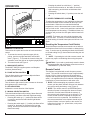
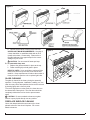
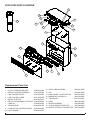
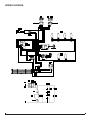
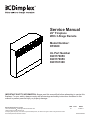
Service Manual
26” Fireplace
With 3-Stage Remote
Model Number:
DF2600
UL Part Number
6901170859
6901170959
6901181300
IMPORTANT SAFETY INFORMATION: Always read this manual first before attempting to service this
fireplace. For your safety, always comply with all warnings and safety instructions contained in this
manual to prevent personal injury or property damage.
Dimplex North America Limited
1367 Industrial Road Cambridge ON Canada N1R 7G8
1-888-346-7539 www.dimplex.com
In keeping with our policy of continuous product development, we reserve the right to make changes without notice.
© 2011 Dimplex North America Limited
REV
PCN
DATE
00
-
21-SEP-11
7400430000R00
TABLE OF CONTENTS
OPERATION. . . . . . . . . . . . . . . . . . . . . . . . . . . . . . . . . . . . . . . . . . . . . . . . . . . . . . . . . 3
MAINTENANCE . . . . . . . . . . . . . . . . . . . . . . . . . . . . . . . . . . . . . . . . . . . . . . . . . . . . . . 4
EXPLODED PARTS DIAGRAM . . . . . . . . . . . . . . . . . . . . . . . . . . . . . . . . . . . . . . . . . . 6
WIRING DIAGRAM. . . . . . . . . . . . . . . . . . . . . . . . . . . . . . . . . . . . . . . . . . . . . . . . . . . . 7
MAIN ON/OFF SWITCH REPLACEMENT . . . . . . . . . . . . . . . . . . . . . . . . . . . . . . . . . . 8
DIMMER CONTROL REPLACEMENT . . . . . . . . . . . . . . . . . . . . . . . . . . . . . . . . . . . . . 8
FLAME SPEED CONTROL REPLACEMENT . . . . . . . . . . . . . . . . . . . . . . . . . . . . . . . 8
FLAME MOTOR/FLAME ROD REPLACEMENT . . . . . . . . . . . . . . . . . . . . . . . . . . . . . 9
MOMENTARY ON/OFF SWITCH. . . . . . . . . . . . . . . . . . . . . . . . . . . . . . . . . . . . . . . . 10
THERMOSTAT CONTROL REPLACEMENT. . . . . . . . . . . . . . . . . . . . . . . . . . . . . . . 10
HEATER ASSEMBLY REPLACEMENT . . . . . . . . . . . . . . . . . . . . . . . . . . . . . . . . . . . 10
POWER CORD REPLACEMENT. . . . . . . . . . . . . . . . . . . . . . . . . . . . . . . . . . . . . . . . . 11
REMOTE RECEIVER BOARD REPLACEMENT . . . . . . . . . . . . . . . . . . . . . . . . . . . . . 11
ASSEMBLY COMPONENT PICTURES . . . . . . . . . . . . . . . . . . . . . . . . . . . . . . . . . . . 12
TROUBLESHOOTING GUIDE . . . . . . . . . . . . . . . . . . . . . . . . . . . . . . . . . . . . . . . . . . 14
Always use a qualified technician or service agency to repair this fireplace.
! NOTE: Procedures and techniques that are considered important enough to emphasize.
CAUTION: Procedures and techniques which, if not carefully followed, will result in damage to the
equipment.
Warning: Procedures and techniques which, if not carefully followed, will expose the user to the
risk of fire, serious injury, or death.
2
www.dimplex.com
OPERATION
•
Figure 1
•
Figure 2
F
D
B
C
A
E
MANUAL CONTROLS
This section will explain the function of each convenient
control.
1. To access the controls, open the upper grille by
pulling, near the top right hand side, forward and
down. (Figure 1). To conceal the controls during the
operation, return the grille to its original upright position.
2. To locate controls see Figure 2.
A. MAIN ON/OFF SWITCH
The ON/OFF SWITCH supplies power to all fireplace
functions (Heater/Flame).
B. FLAME ACTION CONTROL
Turn the flame action control knob to adjust the flame
speed to the desired level.
C. INTERIOR LIGHT CONTROL
Turn the interior light control knob to increase or decrease
the brightness of the interior light.
D. LED INDICATORS
Indicates the current function of the fireplace
E. MANUAL SELECTION SWITCH
To choose between flame effect setting, flame effect with
low heat setting, and flame effect with high heat setting.
• Pressing the switch up (“–” position) the flame effect
is turned on and the first red indicator light flashes
momentarily
• Pressing the switch again (“–” position) the flame effect
remains on, the heater is activated to the low heat
setting, and the first and second red indicator lights
flash momentarily
Pressing the switch for a third time (“–” position)
the flame effect remains on, the heater is set to the
high heat setting, and all three red indicators flash
momentarily
Pressing the switch down (“═” position) turns the unit
off
F. HEATER THERMOSTAT CONTROL
To adjust the temperature to your individual requirements,
turn the thermostat control clockwise all the way to turn
on the heater. When the room reached the desired
temperature, turn the thermostat knob counter clockwise
until you hear a click. Leave in this position to maintain the
room temperature at this setting. For additional heat, turn
clockwise until you hear the click again and the heater will
turn on.
! NOTE: The heater may emit a slight, harmless odor
when first used. This odor is a normal condition caused
by initial heating of internal heater parts and will not occur
again.
Resetting the Temperature Cutoff Switch
Should the heater overheat, an automatic cut out will turn
the fireplace off and it will not come back on without being
reset. It can be reset by switching the Main On/Off Switch
to Off and waiting five (5) minutes before switching the unit
back on.
! NOTE: If operating the unit with a remote control, the
remote may require re-initializing after turning the power
off.
CAUTION: If you need to continuously reset the heater,
disconnect power and call Dimplex customer service at
1-888-DIMPLEX (1-888-346-7539).
Remote Control
The fireplace is supplied with a radio frequency remote
control. This remote control has a range of approximately
50 feet (15.25 m), it does not have to be pointed at the
fireplace and can pass through most obstacles (including
walls). It is supplied with one of hundreds of independent
frequencies to prevent interference with other units.
! NOTE: Before attempting any operation with the
remote, pull the plastic insulator strip out from between
the remote casing and battery cover (Figure 2).
! NOTE: The remote control is an EEPROM system;
therefore if power is interrupted for whatever reason,
the built-in receiver board will hold the memory of
the remote’s radio frequency for up to 24 hours. The
remote should continue to operate the fireplace as
normal once unit is re-powered. Re-initialization of
the remote transmitter to the fireplace should only be
required if there is a loss of power to the receiver for
longer than 24 hours. (i.e. power failure, main power
switch is turned off).
3
Figure 3
On
Button
Off Button
Plastic
Strip
Battery
Cover
Remote Control Initialization/Reprogramming
If the hand held transmitter or receiver board has been
replaced, follow these steps to initialize the transmitter and
receiver:
1. Ensure that power is supplied through main service
panel.
2. Locate manual controls (Figure 1).
3. Activate main power switch, (“─” position) (the red
indicator light 1 may flash, depending on unit).
4. Press and hold the manual selection switch for five
seconds (“─” position) UNTIL the middle red indicator
light flashes.
5. Press ON button located on the left of the remote
control transmitter (Figure 3). This will synchronize the
remote control transmitter and receiver.
Remote Control Operation
The remote control operates the fireplace levels
sequentially. The level is increased every time the ON
button on the transmitter is pressed. The fireplace can be
turned off at any point by pressing the OFF button on the
remote control transmitter.
Level 1
: The flame effect is turned on and the first
red indicator light turns on.
Level 2 : The flame effect remains on, the heater is
activated to the low heat setting, and the first and second
red indicator lights turn on.
Level 3
: The flame effect remains on, the heater is set
to the high heat setting, and all three red indicators will be
turned on.
Battery Replacement
To replace the battery:
1. Slide battery cover open on the hand held transmitter
(Figure 3).
2. Install one (1) 12-Volt (A23) battery in the battery
holder.
3. Close the battery cover
Battery must be recycled or disposed of properly.
Check with your Local Authority or Retailer for
recycling advice in your area.
MAINTENANCE
W
arning: If the fireplace was operating prior to
servicing allow at least 10 minutes for light bulbs and
heating elements to cool off to avoid accidental burning
of skin.
W
arning: Disconnect circuit power before attempting any maintenance or cleaning to reduce the risk of
electric shock or damage to persons.
Light Bulb Replacement
Light bulbs need to be replaced when you notice a dark
section of the flame or when the clarity and detail of the
log exterior disappears. There are two bulbs at the top of
the opening, which illuminate the log set exterior, and four
bulbs under the log set which generate the flames and
embers.
Tool Requirements: Philips head Screwdriver
! NOTE: Before replacing lamps unnecessarily, ensure
that they are not simply loose or that the brightness control
is not adjusted to low setting (see item D in operation
section).
A. To open the light bulb area: (Figure 4)
1. Remove the trim by pulling straight forward.
2. Hold the glass in place while removing the retaining
clip from the upper center of the firebox.
3. Lift glass out and store in a safe place.
CAUTION: Even though the glass is safety glass it
may break if bumped, struck or dropped. Care must be
taken when handling the glass.
HELPFUL HINTS: It is a good idea to replace all light
bulbs at one time if they are close to the end of their
rated life. Group replacement will reduce the number of
times you need to open the unit to replace light bulbs.
B. To replace the bottom light bulbs: (Figure 5)
1. Lift up the front edge of the log until it clears the
front tabs. Pull out until the rear tab clears the back
ledge, and then lift out.
2. Examine the bulbs to determine which bulbs require
replacement.
3. Hold the socket while unscrewing the bulb
4. Hold the socket while screwing in the new bulb.
5. Replace the log by pushing it down and in until it
rests against the mirror.
LOWER LIGHT BULB REQUIREMENTS: Quantity
of 4 clear chandelier or candelabra bulbs with an E-12
(small) socket base, 60 watt rating.
CAUTION: Do not exceed 60 watts per bulb.
C. To replace the top light bulbs: (Figure 6)
1. Locate the two upper bulbs inside the firebox at the
top.
2. Examine the bulbs to determine which bulbs require
replacement.
3. Hold the socket while unscrewing the bulb
4
www.dimplex.com
Figure 4
Figure 5
4. Hold the socket while screwing in the new bulb.
UPPER LIGHT BULB REQUIREMENTS: Quantity of
2 clear chandelier or candelabra bulbs with an E-12
(small) socket base, 15 watt rating. Please refer to
the label adjacent to the upper lamps for the correct
wattage for your model.
CAUTION: Do not exceed 25 watts per lamp.
D. To reassemble lamp area
1. Replace the glass and hold it in place at the top.
2. Fasten retaining clip to hold glass in place.
HELPFUL HINTS: It is a good idea to replace all light
bulbs at one time if they are close to the end of their
rated life. Group replacement will reduce the number of
times you need to open the unit to replace light bulbs.
Figure 6
GLASS CLEANING
The glass is cleaned in the factory during the assembly
operation. During shipment, installation, handling, etc., the
clear door may collect dust particles; these can be removed
by dusting lightly with a clean dry cloth.
To remove fingerprints or other marks, the clear door can
be cleaned with a damp cloth. The clear door should be
completely dried with a lint free cloth to prevent water
spots.
CAUTION: Do not use abrasive cleaners on glass
surface or spray liquids directly onto any surface.
FIREPLACE SURFACE CLEANING
Use a cloth dampened with warm water only to clean
painted surfaces of the electric fireplace. Do not use
abrasive cleaners.
5
EXPLODED PARTS DIAGRAM
16
16
14
9
19
18
15
10
17
13
11
3
12
8
7
1
6
2
5
4
Replacement Parts List
1. GLASS, TEMPERED BRONZE . . . . . . . 5900000100RP
2. GRILLE LOUVERED ASSEMBLY. . . . . 1006720159RP
3. LAMP HOLDER UPPER . . . . . . . . . . . . 4200120600RP
4. LAMP HOLDER LOWER . . . . . . . . . . . . 4200120500RP
5. MOTOR, ELECTRIC. . . . . . . . . . . . . . . 3000240200KIT
6. REFLECTOR ASSEMBLY, ROTATING. 5900080300RP
7. CORD SET. . . . . . . . . . . . . . . . . . . . . . . 4100090104RP
8. STRAIN RELIEF . . . . . . . . . . . . . . . . . . 8500260003RP
9. FLAME ACTION CONTROL BOARD. 3000240100RP
10. LIGHT DIMMER . . . . . . . . . . . . . . . . . . . 3000250100RP
11. GLASS, SEMI-SILVERED. . . . . . . . . . . 5900060100RP
12. LOG . . . . . . . . . . . . . . . . . . . . . . . . . . . . 0437960100RP
13. MAIN POWER - ON/OFF SWITCH . . . . 2800070200RP
14. MOMENTARY ON SWITCH . . . . . . . . . 2800070500RP
15. THERMOSTAT . . . . . . . . . . . . . . . . . . . 2300150100RP*
16. KNOB . . . . . . . . . . . . . . . . . . . . . . . . . . . 8800000300RP
17. HEATER ASSEMBLY . . . . . . . . . . . . . . . 2200490200RP
18. 3-STAGE REMOTE RECEIVER . . . . . . 3000430800RP
19. REMOTE CONTROL TRANSMITTER. 3000370600RP
6
www.dimplex.com
WIRING DIAGRAM
7
MAIN ON/OFF SWITCH REPLACEMENT
Tools Required: Phillips head Screwdriver
Slip Joint Pliers
Flat Head Screwdriver
W
arning: If the fireplace was operating prior to
servicing allow at least 10 minutes for light bulbs and
heating elements to cool off to avoid accidental burning
of skin.
W
arning: Disconnect circuit power before attempting any maintenance or cleaning to reduce the risk of
electric shock or damage to persons.
1. Remove the firebox trim by placing your hand on the
grille section, grasping the sides of the trim and pulling
forward, away from the firebox, releasing the retainer
clips.
2. Remove the firebox from the mantel.
3. Lower the grille covering the controls.
4. Remove the 6 retaining screws on the edges along the
top cover: 2 on the left; 2 on the right; 2 on the back.
Remove the top, placing it upside down on the top of
the unit being careful not to damage any of the wiring.
5. Locate the main on/off switch mounted on the top panel
and disconnect the wiring clips and connections noting
their original locations.
! NOTE: Using a flat head screwdriver gently pry between the end of the connector and the switch to release
the wires.
6. Depress the retainer clips on the sides of the switch
and push the switch forward through the front panel.
7. Push the new switch in place, ensuring that both tabs
are engaged and connect all of the wiring connections
to their original locations.
8. Align the top cover back on the firebox assembly and
secure with 6 retaining screws.
9. Place the firebox in the mantel.
10. Place trim back on firebox by pushing ball studs on trim
into the retainer clips on the firebox.
DIMMER CONTROL REPLACEMENT
Tools Required: Phillips head screwdriver
Flat Head Screwdriver
Adjustable Wrench
Needle nosed pliers
W
arning: If the fireplace was operating prior to
servicing allow at least 10 minutes for light bulbs and
heating elements to cool off to avoid accidental burning
of skin.
W
arning: Disconnect circuit power before attempting any maintenance or cleaning to reduce the risk of
electric shock or damage to persons.
1. Remove the firebox trim by placing your hand on the
grille section, grasping the sides of the trim and pulling
forward, away from the firebox, releasing the retainer
clips.
2. Remove the firebox from the mantel.
3. Lower the grille covering the controls.
4. Remove the 6 retaining screws on the edges along the
top cover: 2 on the left; 2 on the right; 2 on the back.
Remove the top, placing it upside down on the top of
the unit being careful not to damage any of the wiring.
5. Locate the light dimmer control knob mounted on the
top panel and disconnect the wiring connections noting
their original locations.
! NOTE: Using a flat head screwdriver gently pry between the end of the connector and the controller to release
the wires.
6. Pull off the light dimmer control knob to expose the
mounting nut.
7. Remove the mounting nut from the control arm of the
light dimmer.
8. From under the panel, break off the four mounting
studs on the light dimmer control board, push the remainder of the studs out through the top panel.
! NOTE: New mounting studs are supplied with the
replacement dimmer control board.
9. Remove the dimmer control board.
10. Properly orient the new light dimmer board and secure
it to the unit with the included plastic mounting studs.
11. Connect all of the wiring connections to the light dimmer board in their original locations.
12. Install the new dimmer to the front of the top cover with
mounting nut and put the knob on the control arm.
13. Align the top cover with the cabinet assembly and secure with 6 retaining screws.
14. Place the firebox in the mantel.
15. Place trim back on firebox by pushing ball studs on trim
into the retainer clips on the firebox.
FLAME SPEED CONTROL
REPLACEMENT
Tools Required: Phillips head Screwdriver
Flat Head Screwdriver
Slip Joint Pliers
W
arning: If the fireplace was operating prior to
servicing allow at least 10 minutes for light bulbs and
heating elements to cool off to avoid accidental burning
of skin.
W
arning: Disconnect circuit power before attempting any maintenance or cleaning to reduce the risk of
electric shock or damage to persons.
1. Remove the firebox trim by placing your hand on the
grille section, grasping the sides of the trim and pulling
forward, away from the firebox, releasing the retainer
clips.
2. Remove the firebox from the mantel.
3. Lower the grille covering the controls.
4. Remove the 6 retaining screws on the edges along the
8
www.dimplex.com
top cover: 2 on the left; 2 on the right; 2 on the back.
Remove the top, placing it upside down on the top of
the unit being careful not to damage any of the wiring.
5. Locate the flame speed control board mounted on the
top panel and disconnect the wiring connections noting
their original locations.
! NOTE: Using a flat head screwdriver gently pry between the end of the connector and the controller to release
the wires.
6. Pull off the flame speed control knob to expose the
mounting nut.
7. Remove the mounting nut from the control arm of the
flame speed controller.
8. From under the panel, break off the four mounting
studs on the flame control board, push the remainder of
the studs out through the top panel.
! NOTE: New mounting studs are supplied with the
replacement speed control.
9. Remove the flame speed controller.
10. Properly orient the new flame speed controller board
and secure it to the unit with the included plastic mounting studs.
11. Connect all of the wiring connections to the new board.
12. Install the new controller to the front of the top cover
with mounting nut and put the knob on the control arm.
13. Align the top cover with the cabinet assembly and secure with 6 retaining screws.
14. Place the firebox in the mantel.
15. Place trim back on firebox by pushing ball studs on trim
into the retainer clips on the firebox.
FLAME MOTOR/FLAME ROD
REPLACEMENT
Tools Required: Phillips head screwdriver
Wire Cutters
Slip Joint Pliers
W
arning: If the fireplace was operating prior to
servicing allow at least 10 minutes for light bulbs and
heating elements to cool off to avoid accidental burning
of skin.
W
arning: Disconnect circuit power before attempting any maintenance or cleaning to reduce the risk of
electric shock or damage to persons.
1. Remove the firebox trim by placing your hand on the
grille section, grasping the sides of the trim and pulling
forward, away from the firebox, releasing the retainer
clips.
2. Remove the front glass, retaining clip.
3. Remove the front glass and set aside.
4. Remove the log set by lifting up the front edge of the
log until it clears the front tabs. Pull out until the rear
tab clears the back ledge, then lift out.
! IMPORTANT: Only handle the log-set by the plastic
ember-bed, not the logs themselves.
! NOTE: Log-set fits tightly into firebox. Some force
may be necessary to remove.
5. Remove the firebox from the mantel and unplug.
6. Remove 2 screws from the bottom panel located on the
edge of the back assembly.
7. Lay unit on it’s back.
8. Remove the 4 remaining screws from the bottom panel:
2 located on the left and 2 located on the right sides.
9. Remove the bottom panel and set aside.
10. Remove the screw from the motor bracket located in
the flame panel, inside the unit on the left.
11. Remove flicker motor assembly by pulling flicker motor
towards you and by removing bracket from slot located
in back panel.
12. Remove 2 screws securing the flicker motor to the
flicker motor bracket.
13. Cut and strip off approximately 1/2” on the flicker motor
wires at the flicker motor end.
14. Remove reflector rod from flicker motor by bending the
rod down 90º and cutting the reflector spring with wire
cutters. (Read NOTES below).
CAUTION: DO NOT TAKE THE LEFTOVER SPRING
OFF OF THE END OF THE REFLECTOR ROD.
! NOTE: Some units are equipped with a black rubber
cylinder connecting the flicker rod to the motor, if this is the
case there is no need to cut the spring, just gently pull the
assembly apart.
15. Discard old flicker motor.
16. On the new flicker motor, cut and strip the wire leads to
approximately 3 ½” long with wire cutters.
17. Using the provided wire connectors, place the yellow
wires, one into each terminal (total of 2 yellow wires).
18. Secure wire connector by crimping the 3M symbol with
slip joint pliers.
19. Pull on end of wires to ensure a strong connection.
20. Repeat this process for the 4 remaining wires. (Red,
blue, orange, grey)
! NOTE: ENSURE THAT ALL CONNECTORS HAVE
THE SAME WIRE COLORS
21. Pick up the black rubber cylinder and push the smaller
end onto the new motor shaft and the larger end onto
the rod and spring.
! NOTE: Ensure the flicker motor bracket is in between
the motor and the reflector rod.
22. Reassemble in the reverse order.
9
MOMENTARY ON/OFF SWITCH
Tools Required: Phillips head screwdriver.
W
arning: If the fireplace was operating prior to
servicing allow at least 10 minutes for light bulbs and
heating elements to cool off to avoid accidental burning
of skin.
W
arning: Disconnect circuit power before attempting any maintenance or cleaning to reduce the risk of
electric shock or damage to persons.
1. Remove the firebox trim by placing your hand on the
grille section, grasping the sides of the trim and pulling
forward, away from the firebox, releasing the retainer
clips.
2. Remove the firebox from the mantel.
3. Remove the 6 retaining screws on the edges along the
top cover: 2 on the left; 2 on the right; 2 on the back.
Remove the top, placing it upside down on the top of
the unit being careful not to damage any of the wiring.
4. Locate the momentary On/Off switch mounted on the
front top panel and disconnect the wiring clips and connections noting their original locations.
5. Depress the retainer clips on the rear of the switch and
push the switch out of the rear cover.
6. Properly orient the new switch and connect all of the
wiring clips and connections.
7. Align the top cover with the cabinet assembly and secure with 6 retaining screws.
8. Place the firebox in the mantel.
9. Place trim back on firebox by opening grille, grasping
both sides of trim, and hook the trim down into the trim
slots.
! NOTE: The trim slots are located on the front surface
of the firebox.
10. Close the grille.
THERMOSTAT CONTROL
REPLACEMENT
Tools Required: Phillips head screwdriver
Flat Head Screwdriver
W
arning: If the fireplace was operating prior to
servicing allow at least 10 minutes for light bulbs and
heating elements to cool off to avoid accidental burning
of skin.
W
arning: Disconnect circuit power before attempting any maintenance or cleaning to reduce the risk of
electric shock or damage to persons.
1. Remove the firebox trim by placing your hand on the
grille section, grasping the sides of the trim and pulling
forward, away from the firebox, releasing the retainer
clips.
2. Remove the firebox from the mantel.
3. Remove the 6 retaining screws on the edges along the
top cover: 2 on the left; 2 on the right; 2 on the back.
Remove the top, placing it upside down on the top of
the unit being careful not to damage any of the wiring.
4. Locate the thermostat control mounted on the front top
panel and disconnect the wiring clips and connections
noting their original locations.
! NOTE: Using a flat head screwdriver gently pry between the end of the connector and the controller to release
the wires.
5. Pull off the thermostat control knob to expose the
mounting screws.
6. Remove the mounting screws and remove the thermostat control.
7. Properly orient and mount the new heater thermostat
control and connect all of the wiring connections.
8. Reassemble in the reverse order as above.
HEATER ASSEMBLY REPLACEMENT
Tools Required: Phillips head screwdriver
Flat Head Screwdriver
W
arning: If the fireplace was operating prior to
servicing allow at least 10 minutes for light bulbs and
heating elements to cool off to avoid accidental burning
of skin.
W
arning: Disconnect circuit power before attempting any maintenance or cleaning to reduce the risk of
electric shock or damage to persons.
1. Remove the firebox trim by placing your hand on the
grille section, grasping the sides of the trim and pulling
forward, away from the firebox, releasing the retainer
clips.
2. Remove the firebox from the mantel.
3. Remove the 6 retaining screws on the edges along the
top cover: 2 on the left; 2 on the right; 2 on the back.
Remove the top, placing it upside down on the top of
the unit being careful not to damage any of the wiring.
4. Locate the heater assembly mounted on the top panel
and disconnect the wiring clips and connections noting
their original locations.
! NOTE: Using a flat head screwdriver gently pry between the end of the connector and the heater to release
the wires.
5. Turn the top back over, remove the 6 heater mounting
screws, being careful to support the heater assembly
as you do this.
6. Remove the 4 screws attaching the vent/deflector
around the elements; 2 top and 2 bottom.
7. Properly orient the new heater assembly and connect
all of the wiring connections.
8. Reassemble in the reverse order as above.
10
www.dimplex.com
POWER CORD REPLACEMENT
Tools Required: Phillips head screwdriver
Needle nosed pliers
W
arning: If the fireplace was operating prior to
servicing allow at least 10 minutes for light bulbs and
heating elements to cool off to avoid accidental burning
of skin.
W
arning: Disconnect circuit power before attempting any maintenance or cleaning to reduce the risk of
electric shock or damage to persons.
1. Remove the firebox trim by grasping both sides of the
trim and pulling straight up.
2. Remove the firebox from the mantel.
3. Remove the 6 retaining screws on the edges along the
top cover: 2 on the left; 2 on the right; 2 on the back.
Remove the top, placing it upside down on the top of
the unit being careful not to damage any of the wiring.
4. Locate and disconnect the power cord wiring connections noting their original locations.
5. With needle nose pliers grasp the power cord strain
relief grommet from inside the right rear of the panel
and push while twisting to remove.
6. Pull the power cord out through the hole in side of the
unit.
7. Insert the new power cord through the hole and connect all of the wiring connections in their original locations.
8. Install the power cord strain relief grommet on the
replacement power cord and insert into the mounting
hole.
W
arning: Ensure wires do not come in contact with
moving parts by securing wires in wiring tie wraps.
9. Reassemble in the reverse order as above.
Remove the top, placing it upside down on the top of
the unit being careful not to damage any of the wiring.
5. Locate the remote receiver board next to the thermostat control and disconnect the wiring connections noting their original locations.
! NOTE: Markings on the new board may appear different than the original, however position of the wires on the
new board should be the same configuration as the original
board.
6. From under the panel, break off the four mounting
studs on the remote receiver board, push the remainder of the studs out through the top panel.
! NOTE: New mounting studs are supplied with the
replacement remote receiver board.
7. Remove the remote receiver board.
8. Properly orient the new receiver board and secure it to
the unit using the new plastic mounting studs.
9. Connect all of the wiring connections according to their
original configuration.
10. Reassemble in the reverse order as above.
REMOTE RECEIVER BOARD
REPLACEMENT
Tools Required: Phillips head screwdriver
Needle nosed pliers
W
arning: If the fireplace was operating prior to
servicing allow at least 10 minutes for light bulbs and
heating elements to cool off to avoid accidental burning
of skin.
W
arning: Disconnect circuit power before attempting any maintenance or cleaning to reduce the risk of
electric shock or damage to persons.
1. Remove the firebox trim by placing your hand on the
grille section, grasping the sides of the trim and pulling
forward, away from the firebox, releasing the retainer
clips.
2. Remove the firebox from the mantel.
3. Lower the grille covering the controls.
4. Remove the 6 retaining screws on the edges along the
top cover: 2 on the left; 2 on the right; 2 on the back.
11
ASSEMBLY COMPONENT PICTURES
EXTERIOR VIEW OF MANUAL CONTROLS
Flame Action Control
Knob
Interior Light Control
Manual Selection
Switch
LED Indicator Lights
Main On/Off Switch
Thermostat Control
Knob
Front Grille Open
INTERIOR VIEW FROM THE BOTTOM
Light Sockets
Flame Rod
Flame Motor
12
www.dimplex.com
INTERIOR VIEW OF RIGHT SIDE, TOP & FRONT PANEL
Potentiometers (flame
speed & dimmer controls)
Heater Assembly (blower
motor; fan; elements)
Main Power ON/OFF
Switch
Flame Speed Control
Board
Dimmer Control Board
Terminal Block
INTERIOR VIEW OF LEFT SIDE, TOP & FRONT PANEL
Momentary-ON Switch
Thermostat Control
3-Stage
Remote Receiver Board
13
TROUBLESHOOTING GUIDE
Problem
Cause
Solution
General
Circuit breaker trips or fuse
blows when unit is turned on
Short in unit wiring.
Trace wiring in unit.
Improper circuit current rating
Additional appliances may exceed the current rating
of the circuit breaker or fuse. Plug unit into another
outlet or install unit on a dedicated 15 amp circuit.
Unit turns on or off by itself
Remote control has a similar frequency
to other remotes in the area.
Replace Remote Control
Radio frequency disturbance from outside sources.
Replace hand held remote control and receiver board
where necessary.
Defective circuit board
Replace circuit board
Lights dim in room while the unit
is on
Unit is drawing close to circuit current
rating
Move the unit to another outlet or install unit on a dedicated 15 amp circuit
Power cord gets warm
Normal Operation
The power cord may get slightly warm to the touch
when the heater is on
Defective power cord
Replace power cord if cord gets hot to the touch.
Appearance
Fireplace does not turn on Manu- Improper operation
ally
No incoming voltage from the electrical
wall socket
Fireplace does not turn on using
the Remote Control
Refer to Operation Section
Check Fuse/Breaker Panel
Defective 3-Position On/Off switch
Replace 3-Position On/Off switch
Loose wiring
Check wiring connections
Defective circuit board
Replace circuit board
Improper operation
Refer to Operation Section
Remote control not initialized to fireplace
Initialize the remote control
Defective remote control
Install new battery into the handheld transmitter. Reconfigure remote where necessary
Replace remote control circuit board where necessary
Flame Frozen
Defective flame motor
Replace flame motor
Loose wiring
Check wiring connections
Burnt light bulbs
Replace light bulbs
Loose wiring
Check wiring connections
Defective light harness
Replace light harness
Log set dim, not glowing
Burnt light bulbs
Replace light bulbs
Flame Shutter
Defective flame motor
Replace flame motor
Light leaking around the log set
Log set not positioned properly
Check log set for proper fit
Improper operation
Refer to Operation Section
Defective heater on/off switch
Replace heater on/off switch
Loose wiring
Trace wiring in unit
Defective remote control
Replace remote control
Defective circuit board
Replace circuit board
Defective Thermostat
Replace Thermostat
Flame not bright or flame not
visible
Heater
Heater is not turning off
14
www.dimplex.com
Problem
Cause
Solution
Heater Continued
Heater is not turning on
Improper operation
Refer to Operation Section
Defective heater assembly
Replace heater assembly
Defective heater on/off switch
Replace heater on/off switch
Defective Thermostat
Replace Thermostat
Heater is turning off after a
couple of minutes of operation
Build up of dirt/dust in heater assembly
Clean out heater assembly
Defective Motor
Replace Motor
Heater emits an odor
Normal Operation
Normal operation is when the heater emits an odor
for a brief period after the heater is initially turned on.
The heater is burning off any dust accumulated during
manufacturing or operation.
Defective heater assembly
Replace heater assembly
Improper operation
Refer to Operation Section
Defective thermostat
Replace thermostat
Loose wiring
Trace wiring in unit
Defective heater assembly
Replace heater assembly
Normal Operation
Small glowing sections of the element are considered
normal.
Defective heater assembly
If larger glowing sections are causing the heater to trip
the thermal cutout, unplug unit, discontinue use and
replace heater assembly.
Excessive noise with the heater
on
Dirty blower assembly
Clean blower assembly
Defective blower assembly
Replace heater assembly
Grinding or excessive noise with
the heater off
Moving flame rod hitting or rubbing
against internal components
Ensure rod is straight and mounted properly in the
bracket, spinning freely away from other components.
Replace if necessary.
Defective flame motor
Replace flame motor
Heater fan turns on but heater
lacks heat
Heating element is glowing red
Noise
15