1
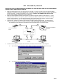
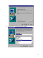
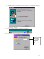
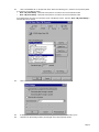
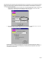
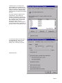
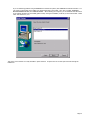
Bitronics Switch Kit User Manual P72655 READ THIS MANUAL IN ITS ENTIRETY BEFORE ATTEMPTING TO CONNECT DEVICES, THE BITRONICS SWITCH, OR INSTALLING THE SOFTWARE. IMPROPER SETTINGS OR CONFIGURATIONS CAN CAUSE DATA CORRUPTION. I. Introduction Thank you for purchasing the Belkin Components Bitronics DualBus Switch Kit! Now, you and your colleague can share and select between two different parallel devices from your desktop. Plus, if you are using Windows 95 or 98, you will take advantage of Virtual Port Software, which allows you to print automatically! The Bitronics DualBus Switch gives you and another computer the ability to communicate to two parallel devices at the same time. Also, it allows you to switch so that either user can use either device through the switching software. II. • • • • • Package Contents Bitronics DualBus Switch, 2-2 F1U127 Power Adapter, 9VDC, 600mA F1D065-PWR 2 x IEEE 1284 compliant cables F2A047-06 User manual P72655 Registration card P72009 III. Product Detail Connectors to Devices Device LEDs Computer LEDs Connectors to Computers Optional Power Jack 9VDC, 500mA, Center positive DIP Switches Manual select buttons DIP Switch Settings (ON is Down) SW1 – RESET switch ON: Normal Operation OFF: RESET the switch SW2 and SW3 – Time Out setting. Time Out is the amount of time the switch remains locked on a computer after data transfer. Use a longer Time Out when connecting to Scanners, Mass Storage Devices, or when printing large print jobs. SW2 SW3 Time Out Setting ON ON 5 seconds ON OFF 10 seconds ! Recommended OFF ON 20 seconds OFF OFF 40 seconds SW4 – Not used Page 2 IV. • • • Choose your Operating System Windows 3.x " Continue below: Windows 95/98 and NT " Continue to next page. MS-DOS " Continue below: V. Manual Mode In manual mode, you can select port manually through the buttons on the Bitronics switch. • • • • Press computer to select which computer port you wish to configure. For the computer connected to Port 1, press the COMPUTER button until the LEDs on Port 1 are lit up either in red or green. When you have selected which computer you wish to configure, now press the PRINTER button until the LED of the appropriate device port you wish to use is lit up. For example, if you want computer 2 to use the device on port A, press the COMPUTER button until the LEDs on “2” are lit up. Then, press the PRINTER button until LED “A” is lit up. To use File Transfer mode, press the printer button until the LEDs on the computer ports turn green. That means that that port is ready for file transfer mode. For file transfer mode to be successful for both PCs, the both computer ports must be set file transfer mode – which is evident when the LEDs next to “1” and “2” are green. For more information on File Transfer, please see page 12. VI. Windows 3.x Printer Button Computer Button In Windows 3.x, you will have to exit to MS-DOS first to make this easier: 1. At the C:\> prompt, type the following and press ENTER: md c:\Belkin 2. Insert the floppy disk containing the Windows 3.x software (part# P72736) into your a: drive. 3. At the next prompt, type the following and press ENTER: copy a:\Win3.x\F1U125e.exe c:\Belkin 4. When you get the prompt back, restart your computer and go back into Windows. 5. Lastly, you will have to create a shortcut to the program. In the Program Manager, select the Start Up window by clicking on WINDOW, then START UP. 6. Click on FILE, NEW, PROGRAM ITEM, then OK. The next window must be filled out like this: When done, click OK. In Windows 3.x, there is no possibility in making the software automatic because of the limitations of the operating system. Hence, you will need to use this software each time you need to switch ports. Since it is in the START UP program group, each time you start Windows, the program will be running. Page 3 VII. MS-DOS In MS-DOS, there re two files which can be used, and both are in the first disk (part# P72735) in the DOS subdirectory. These files are: • DOSSWTCH.com • F1U125.com DOSSWTCH.com is a directly executable program. You must follow the syntax in order to invoke the switch to change ports. For example, entering the following, DOSSWTCH LPT1 A will cause the switch to set your current computer to connect to Port A. F1U125.com is a TSR program. Once it is loaded, it stays in memory. You can access it in any non-protected DOS-mode program by pressing both SHIFT keys simultaneously. The following window will pop-up: To make a selection, hit ENTER, and to go back, hit ESC. You can also change the “Hot Key” from the default L_SHIFT and R_SHIFT, to something else you prefer. Page 4 VIII. Windows 95 / 98 and NT BEFORE YOU INSTALL THE BELKIN BITRONICS SOFTWARE, YOU MUST FIRST MAKE SURE THAT EACH DEVICE WORKS PROPERLY ON ITS OWN WITH EACH COMPUTER 1. 2. 3. Make sure that the printer port on your computer is set to ECP mode. To do this, you must go into your computer’s BIOS or CMOS setup. Instructions on how to do this differ from one computer to the next. Please consult your computer manufacturer’s manual, tech support, or website for information on how to do this. Please do not call Belkin Tech Support on this because each computer’s BIOS setup routine is different. Make sure that the software and drivers for the devices to be shared are properly installed on both computers. If you are sharing two printers between two computers, make sure that the printer drivers for both printers are installed and working properly on both computers. If you are sharing a Zip drive and a scanner between two computers, make sure that the software and drivers of each device are installed and working properly on both computers. Connect the two computers, and the device to be shared to the Bitronics Switch as shown below. The cables from the computers to the Bitronics switch are included in the package. Take note of which port each device is connected to: The example shown has a Zip drive connected to Port A and an InkJet printer on Port B of the switch. Device B connected to Port B Device A connected to Port A These two cables included 4. In order for both computers to properly share the devices, the software must be installed on both computers. 4.1. Put the disk into your floppy drive. Click on START, then RUN. Enter a:\BITRONIX.exe, then click OK 4.2. You will see the following window. Click SETUP. Page 5 4.3. Close all other running applications so that the software installation can proceed quickly and smoothly. Click NEXT. 4.4. Select the model of Bitronics Switch you have, which is the F1U127 / F1U128. Click NEXT. Page 6 4.5. Select destination folder. The default folder is recommended. Click NEXT. 4.6. Select Program Folder. The default is the recommended. Click NEXT. Page 7 4.7. When done installing, the program will ask you to restart your computer. You must restart in order to activate the software properly. Click FINISH. 5. Once your computer has rebooted, the Bitronics icon will appear in your system tray. 6. Double-click on the icon to open up the setup program: Select the correct LPT port the Bitronics switch is connected to. If you only have ONE parallel port (usually that is the case), leave this in LPT1. Page 8 7. Click on SETTINGS. Here, we have to tell the software what devices are connect to which port: DISPLAY NAME is a free text field. You can enter any description here for the attached devices. For instance, Port A has the Zip drive connected and Port B has the InkJet connected. You can rename these fields to say “My Zip Drive” and “Color Printer #2”. DEVICE TYPE gives you a pull-down menu showing the types of printers installed on your computer and other parallel devices as well. Here, you must select the correct type for the device connected to that port. • If you are using a device which adds a drive letter to your system (like a Zip Drive, CD-ROM, LS-120, etc...), use MASS STORAGE DEVICE. • If you are using a printer, use the printer driver used for that particular printer on that port of the Bitronics switch. If it does not show up in this menu, that means the printer drivers have not been installed. (If not, reinstall the printer drivers and repeat this step after rebooting your computer.) If you have more than one printer installed, make sure that the correct driver is used for the printer connected to that port on the Bitronics switch. • For any other parallel device, just use SCANNER, and change the DISPLAY NAME accordingly. For example, if you have a parallel tape drive, use SCANNER for DEVICE TYPE, then enter “Tape Drive” in DISPLAY NAME. Click OK when done. 8. If one or both of the devices being shared is a printer, you must follow the procedure below to reconfigure the port connected to the printer. If both devices are printers, then this must be done for both printers. 8.1. 8.2. Click on START, SETTINGS, PRINTERS. Right-click on the printer installed on the Bitronics switch, and click on PROPERTIES: Page 9 8.3. Click on the DETAILS tab. In the pull-down menu “Print to the following port:”, select the correct port this printer is connected to on the Bitronics switch: • LPx1 – PA (auto switch) " Select this if the printer is connected to Port A of the Bitronics switch • LPx1 – PB (auto switch) " Select this if the printer is connected to Port B of the Bitronics switch In the image below, the printer is connected to Port B of the Bitronics switch. Therefore, LPx1 – PB (auto switch) is selected. When done, click OK. 8.4. Click on SPOOL SETTINGS and click on “Start printing after last page is spooled”. 8.5. 8.6. If NOT grayed out, click on “Disable bi-directional support for this printer”. Otherwise, ignore. Click OK in the Spool Settings window, and OK again in the main properties window. Page 10 Using the Bitronics Software Example: Two Printers Shared Between Two Computers The Bitronics Software automatically handles printing chores by directing your print jobs to the correct port on the switch based on the settings you set in the Printer Properties and the Settings in step 7 previously. When you print something in Windows, you simply select the printer you wish to print to, and the Bitronics software handles the switching duties. ITS FULLY AUTOMATIC! How does it work? The Bitronics software tells the Bitronics switch to switch to the port the selected printer is connected to. In the example below, the Bitronics software tells the Bitronics switch to switch to Port B first, then it allows the print job to go through the switch, out to Port B, and to the Epson printer. Then if you wish to print to the second printer, let’s say a LaserJet for example, all you have to do is select that particular printer in the PRINT dialog box. Click OK, and the print job is automatically sent to the LaserJet printer on Port A of the Bitronics switch. Example: Sharing One Printer and a Zip drive (or any other mass storage device) Page 11 When dealing with a mass storage device (devices that add a drive letter to your system like “E:”) such as a Zip drive, the Bitronics Software in the system tray must be configured so that the Bitronics switch is defaulted to the Port attached to the Zip drive. It is necessary for the switch to always remains connected to the Zip drive so that anytime you access that drive, you will always be connected, and not get error messages: 1. Make sure that the port that connects to the Zip drive is set to MASS STORAGE DEVICE in settings. See Step 7 above for more info. The image below shows the Zip drive is connected to Port A, and that the device type is MASS STORAGE DEVICE. Type anything you want in Display Name. Click OK when done. 2. Click on the port that has the mass storage device connected. In this case, it is a Zip drive on Port A. As you can see, the Display Name entered above appears below as you had entered it. Click OK. Now what happens is that the Bitronics switch always keeps your computer connected to the Zip drive. That way, anytime you access it, you will not get any strange errors. Then when you print to the Ink Jet Printer on Port B (as shown above), the Bitronics switch will switch to Port B temporarily to send the print job, then switch back to Port A to keep communication with the Zip drive. Page 12 Visual Feedback – How do I know what port I am on? When the Bitronics switch is in its normal scanning mode, the LEDs are flipping back and forth across the computer ports. To see the software in action, simply hit the COMPUTER button so you can see a computer port’s connection. Press the COMPUTER port until the LEDs around “1” are lit up, and you will see which device port it is currently connected to. If it is in File Transfer mode, the computer port LEDs are green, and neither device port LEDs will be lit. Then, click on the Bitronics software icon in the taskbar and change ports. You will see the LED of the Bitronics switch to the port you chose. Using any other parallel device (not printers or mass storage devices) with a printer When dealing with other parallel port devices, they are set as SCANNERS in the SETTINGS (step 7 above). Examples of these are scanners, parallel port cameras, and tape drives. When you need access to this device, simply single-click on the Bitronics system tray icon, and select the device you wish to use. A check mark will appear showing which device is connected. For example, we have a scanner and a printer on the Bitronics switch: You will be connected to the scanner device indefinitely. But lets say you wish to print to the Ink Jet printer, the software will again automatically switch to the port that has the printer and send the print job. However, the switch will remain connected to the printer - it will not change back to the Scanner, unlike the mass storage device mentioned previously. This means that you have to use this method to switch to the scanner each time you need to use it. If no printers are installed If no printers are installed, the SETTINGS type (see step 7) for each device must be set either for MASS STORAGE DEVICE (if the device adds a drive letter to your system), or SCANNER (for all other types of devices). The Bitronics software may not function properly in some systems if there is no DEFAULT PRINTER set. To do this, add a printer using the Add Printer Wizard (click START, SETTINGS, PRINTERS), and just use the “Generic / Text Only” driver. Remember to use “Local Printer” and “LPT1” when the wizard asks you. This will then be set as your default printer, so that the Bitronics software can work properly. Removing and Adding the Bitronics Switch Icon from the System Tray • To remove the icon, simply right click on it, and answer YES to the prompt. • To reload the icon back into the system tray, click on START, PROGRAMS, BELKIN BITRONICS SWITCH, “AutoSwitchMulti PCs” Using the File Transfer Feature The file transfer feature of the Bitronics switch allows both computers to connect as if there was a file transfer cable connected between them. To do this, double-click on the Bitronics switch system tray icon, and click on FILE TRANSFER: A set of PC LEDs on the Bitronics switch will turn green. These LEDs represents the computer you are on now is set for file transfer mode. Next, the second PC must also perform the same operation. When both sets of PC LEDs on the Bitronics switch are green (all four), then the computers are ready for file transfer. At this point, the cables and the Bitronics switch act as if it was a file transfer cable. You can now run programs such as Windows Direct Cable Connection, or Laplink. Please refer to their user manuals or websites for information on how to configure their software. Just remember that your Bitronics switch setup mimics the file transfer cable requirement. Usage in Windows NT Page 13 In Windows NT, you can perform the same installation as in the Windows 95 /98 procedure above. Make sure the power supply is connected to the Bitronics switch, otherwise, there may be a significant delay in the processing of requests from NT-based machines. The Printer properties in Windows NT is slightly different. After installing the software and restarting the computer, go the printer properties and select the PORTS tab. To find the correct ports to be used with the Bitronics switch, you must scroll down the list until the “LPx1: PA (autoswitch)” comes up. Put a checkmark on the port that connects to the printer. In this case, it is Port A on the Bitronics switch: To set the spool settings correctly, click on the SCHEDULING tab. Make sure “Start printing after last page is spooled” is selected. Also, set “Priority” to highest: Click OK when done. Page 14 If you are still having problems using the BITRONIX.exe software setup above, first UNINSTALL the Bitronics software. You can do this by right-clicking on the taskbar icon and answering YES to the prompt. Then, click on START, PROGRAMS, BELKIN BITRONICS SWITCH, then UNINSTALLSHIELD. After restarting your computer, you can install the older NT version of the software located in the second disk (part# P72736). During the installation, it will ask you the model number. Please select “Auto Switch 2-2 / 4-2”: This version of the software is not fully automatic in printer selection. It requires the user to select ports each time through the taskbar icon. Page 15 1999 Belkin Components® Components Corporate Headquarters 501 West Walnut Street Compton, CA 90220 310-898-1100 voice Tech Support x 2263 310-898-1111 fax DECLARATION OF CONFORMITY WITH FCC RULES FOR ELECTROMAGNETIC COMPATIBILITY We, Belkin Components, of 501 West Walnut Street, Compton CA 90220, declare under our sole responsibility that the product: F1U127-KIT Bitronics Switch Kit to which declaration relates: Complies with Part 15 of the FCC Rules. Operation is subject to the following two conditions: (1) this device may not cause harmful interference, and (2) this device must accept any interference received, including interference that may cause undesired operation. CE Declaration of Conformity We, Belkin Components, declare under our sole responsibility that the F1U127-KIT Bitronics Switch Kit to which this declaration relates, is in conformity with Generic Emissions Standard EN50081-1 and with Generic Immunity Standard EN50082-1 1992. Belkin Components Limited Lifetime Warranty Belkin Components warrants this product against defects in materials and workmanship for its lifetime. If a defect is discovered, Belkin will, at its option, repair or replace the product at no charge provided it is returned during the warranty period, with transportation charges prepaid, to the authorized Belkin dealer from whom you purchased the product. Proof of purchase may be required. This warranty does not apply if the product has been damaged by accident, abuse, misuse, or misapplication; if the product has been modified without the written permission of Belkin; or if any Belkin serial number has been removed or defaced. THE WARRANTY AND REMEDIES SET FORTH ABOVE ARE EXCLUSIVE IN LIEU OF ALL OTHERS, WHETHER ORAL OR WRITTEN, EXPRESSED OR IMPLIED. BELKIN SPECIFICALLY DISCLAIMS ANY AND ALL IMPLIED WARRANTIES, INCLUDING, WITHOUT LIMITATION, WARRANTIES OF MERCHANTABILITY AND FITNESS FOR A PARTICULAR PURPOSE. No Belkin dealer, agent, or employee is authorized to make any modification, extension, or addition to this warranty. BELKIN IS NOT RESPONSIBLE FOR SPECIAL, INCIDENTAL, OR CONSEQUENTIAL DAMAGES RESULTING FROM ANY BREACH OF WARRANTY, OR UNDER ANY LEGAL THEORY, INCLUDING BUT NOT LIMITED TO LOST PROFITS, DOWNTIME, GOODWILL, DAMAGE TO OR REPROGRAMMING, OR REPRODUCING ANY PROGRAM OR DATA STORED IN OR USED WITH BELKIN PRODUCTS. Some states do not allow the exclusion or limitation of incidental or consequential damages or exclusions of implied warranties, so the above limitations of exclusions may not apply to you. This warranty gives you specific legal rights, and you may also have other rights that vary from state to state. Page 16