1
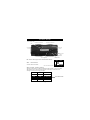
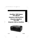
Bitronics DualBus
Switch Kit
User Manual
P73045
F1U128-KIT
Introduction
Thank you for purchasing the Belkin Components Bitronics DualBus Switch
Kit! Now, you and your colleagues can share and select between two
different parallel devices from your desktop. And, if you are using
Windows® 95, 98 or NT®, you will be able to take advantage of Bitronics
Software, which allows you to print automatically even if you have more
than one printer!
Features
•
Allows four computers to access any two parallel devices simultaneously
and independently
•
Virtual Port printer driver software allows fully automatic printer selection
through Windows® 95/98 and NT®
•
File-transfer feature between two PCs compatible with Windows® Direct
Cable Connection, LapLink® and DOS Interlink™
•
Includes two 6 ft. (1.8m) IEEE 1284-compliant cables to connect the computers
•
Includes power adapter
•
Adjustable timeout
Package Contents:
Bitronics DualBus Switch, 4-2
F1U128
Power Adapter, 9VDC, 600mA
F1D065-PWR (US)
2 x IEEE 1284-compliant cables
F2A047-06
User manual
P73045
Registration card
P72009
Other Parts Needed (if necessary)
•
IEEE 1284 printer cable, Belkin Part# F2A046-XX. You will need this
cable to connect a printer to the autoswitch. Your current printer cables
may work, but IEEE-compliant cables are recommended.
•
IEEE 1284 device cable, Belkin Part# F2A047-XX. You will need this
cable to connect a computer to the autoswitch.
NOTE:
"XX" is the length in feet.
1
Technical Specifications
Compatible Standards:
IEEE 1284-1994 Parallel Port Communication Standard
Electrical:
Input Voltage
Max Input Current
Max Power Consumption
Max Heat Dissipation
9VDC
600mA
5.4W
0.31 BTU/min
Dimensions:
Width:
Height:
Depth:
Weight:
Storage Temperature:
7.0” (17.8cm)
3.75” (9.5cm)
1.25” (3.2cm)
7.1 oz. (202 g)
-10ºC to 50ºC
(14ºF to 122ºF)
0ºC to 40ºC
(32ºF to 104ºF)
0 to 95%
Non-condensing
Operating Temperature:
Humidity:
2
Product Detail
Device activity LEDs
Connector to Device B
Connector to Device A
Connector
to PC1
Connector
to PC4
DC power jack
(side)
Connector to PC2
Connector to PC3
PC activity LEDs
DIP switch settings (located underneath switch):
SW1:
Computer button
Printer button
ON
DIP
Reset Switch
To reset, OFF→ON→OFF
ON is UP. SW4 is not used.
1
2
3 4
SW2 and SW3: TimeOut Setting
TimeOut is the amount of time the switch remains locked on a PC port after
data transfer. Use a longer TimeOut when connecting to scanners, mass
storage devices and for large print jobs.
SW2
SW3
TimeOut
ON
ON
5 seconds
ON
OFF
10 seconds
OFF
ON
20 seconds
OFF
OFF
40 seconds
3
Recommended
Manual Mode and Port Monitoring
In manual mode, you can select a port manually through the buttons on the
Bitronics switch. You can also use this mode in conjunction with software to
see your switch in action!
•
Press COMPUTER to select which computer port you wish to configure or
monitor. For the computer connected to Port 1, press the COMPUTER
button until the LED on Port 1 is lit up either in red or green.
•
Press the PRINTER button until the LED of the appropriate device port
you wish to use is lit up.
For example, if you want
computer 2 to use the
device on port B, press the
COMPUTER button until the
LED on "2" is lit up. Then,
press the PRINTER button
until LED "B" is lit up.
Printer button
Computer button
To use File Transfer mode, press the PRINTER button until the LED on the
computer port turns green. When the LED turns green, the port is ready for
file transfer mode. For file transfer mode to be successful for both PCs, both
computer ports must be set to file transfer mode – which is evident when the
LEDs next to 1 and 2 are green. For more information on File Transfer, please
see page 25.
Note:
Computer 1 can only file transfer to computer 2, and computer
3 can file transfer to computer 4. If you change the ports
manually using the buttons, the changes made will not be
reflected in the software.
4
Choose your operating system
Windows® 3.x . . . . . . . . . . . . . . . . . . . . . . . . . . . . . . . . . . . . . . . . . Page 6
MS-DOS . . . . . . . . . . . . . . . . . . . . . . . . . . . . . . . . . . . . . . . . . . . . . Page 7
Windows® 95/98 and NT® . . . . . . . . . . . . . . . . . . . . . . . . . . . . . . . . . Page 8
NOTE:
When installing software on any operating system, the
software must be installed on all the computers connected to
the Bitronics switch so that each machine can control the
switch properly.
5
Software installation: Windows® 3.x
Insert the diskette labeled P27236 in your floppy drive. In the Program
Manager, click on File then click Run. In the space, type in "a:\setup.exe".
Follow the installation instruction prompts. After the setup program is done,
simply double-click on the correct icon to run the port selection program.
6
Software installation: MS-DOS
To switch port, simply click on the port letter of your choice, and your
computer will be connected to the device on the port chosen.
Software-Installation: MS-DOS
Enter the following at the DOS prompt and press ENTER:
Copy a:\dos\swport.com c:\SWPORT.com
SWPORT.com is a command-line executable. Please follow the syntax for
proper operation:
File Transfer in DOS and WINDOWS® 3.x:
The file transfer feature of the Bitronics switch allows both computers to
connect a if there was a file transfer cable connected between them.
The LED of the corresponding computer port on the Bitronics switch will
turn green. This LED represents the computer you are on now, and is set for
file transfer mode.
The LED of the corresponding computer port on the Bitronics switch will
turn green. This LED represents the computer you are on now is set for file
transfer mode. Note that PC1 can only file transfer to PC2, and PC3 can
only file transfer to PC4. When both sets of PC LEDs on the Bitronics switch
are green, then the computers are ready for file transfer. At this point, the
cables and the Bitronics switch act as if it was a file transfer cable. You can
now run programs such as Windows‚ Direct Cable Connection, or LapLink®.
Please refer to their user manuals or websites for information on how to
configure their software. Just remember that your Bitronics switch setup
mimics the file transfer cable requirement.
7
Windows® 95 / 98 and NT®
BEFORE YOU INSTALL THE BELKIN BITRONICS SOFTWARE, YOU MUST
FIRST MAKE SURE THAT EACH DEVICE WORKS PROPERLY ON ITS OWN
WITH EACH COMPUTER. DO NOT CONNECT THE BITRONICS SWITCH TO
THE COMPUTERS OR INSTALL THE SOFTWARE UNTIL INSTRUCTED BY
THIS PROCEDURE!
1.
Make sure that the printer port on your computer is set to ECP mode. To
do this, you must go into your computer’s BIOS or CMOS setup.
Instructions on how to do this differs from one computer to the next.
Please consult your computer manufacturer’s manual, tech support, or
website for information on how to do this. Please do not call Belkin Tech
Support regarding this because each computer’s BIOS setup routine is
different. Refer to the Appendices at the end of this manual for
information on several models of computers.
The BIOS setup routine prompt is displayed a few seconds after you turn
on your computer and hear its first beeps. Again, this varies from PC to
PC. Please consult the Appendices and/or your computer manufacturer’s
manual or their tech support for information on how to do this properly.
Usually you will see a message that reads PRESS DEL TO ENTER SETUP or
PRESS F2 TO ENTER SETUP. When in the setup program, there may be a
selection for "Integrated Peripherals", or "Peripheral Setup". Then, look
for "Parallel Port Type" or "LPT port type". Change that setting to say
"ECP" or "ECP/EPP". Save your settings then exit. When Windows®
restarts, it may find new hardware, and it may ask you for the Windows®
CD. Be prepared to insert the CD into the computer.
2.
Make sure that the software and drivers for the devices to be shared are
properly installed on all computers.
For instance, if you are sharing a Zip® Drive and a printer between 2
computers, you will need to first connect and install the Zip® Drive drivers
on the first PC. Make sure that the Zip® Drive works perfectly on it, then
repeat the same installation process for the second PC. Then, you will
need to do the same installing the printer’s driver on both PCs as well.
This way, all the PCs have the drivers properly loaded so each one can
access either device without any problems, as if they were connected to
the computer individually.
8
Windows® 95 / 98 and NT® (continued)
3.
Connect four computers and the devices to be shared to the Bitronics
Switch as shown below. Two cables that connect computers to the
Bitronics switch are included. Take note of which port each device is
connected to:
Device A
connected to Port A
Device B
connected to Port B
These two cables
are included
Connect the power adapter to the power jack on the side of the switch,
and plug it into an outlet. The example shown has a Zip® Drive connected
to Port A and an InkJet printer on Port B of the switch.
9
Windows® 95 / 98 and NT® (continued)
4.
In order for all computers to properly share the devices, the software must
be installed on all four computers.
4.1. Insert the disk into your floppy drive. Click on Start, then click Run.
Enter a:\BITRONIX.exe, then click OK.
4.2. You will see the following window. Click Setup.
4.3. Close all other running applications so that the software installation
can proceed quickly and smoothly. Click Next.
10
Windows® 95 / 98 and NT® (continued)
4.4. Select the model of the Bitronics Switch you have, which is the
F1U127 / F1U128. Click Next.
4.5. Select Destination Folder. The default folder is recommended.
Click Next.
11
Windows® 95 / 98 and NT® (continued)
4.6. Select Program Folder. The default, Belkin Bitronics Switch, is the
recommended. Click Next.
4.7. When done installing, the program will ask you to restart your
computer. You must restart in order to activate the software properly.
Click Finish.
Don’t forget to remove the disk from your floppy drive before
restarting your computer!
12
Windows® 95 / 98 and NT® (continued)
5.
Once your computer has rebooted, the Bitronics icon will appear in
your system tray. This is how you can easily control and configure the
Bitronics Switch.
6. Double-click on the icon to open up the setup program:
Select the correct LPT
port the Bitronics
switch is connected to.
If you only have ONE
parallel port (usually
that is the case), leave
this in LPT1.
13
Windows® 95 / 98 and NT® (continued)
7.
Click on Settings. This is where you tell the software what devices are
connected to each port:
Device Type gives you a pull-down menu showing the types of printers
installed on your computer and other possible parallel device types as well.
Here, you must select the correct type for the device connected to that port.
•
If you are using a device which adds a drive letter to your system (like a
Zip® Drive, CD-ROM, LS-120, etc...), use the Mass Storage
Device setting.
•
If you are using a printer, use the printer driver used for that particular
printer on that port of the Bitronics switch. If it does not show up in this
menu, that means the printer drivers have not been installed. (In that
case, reinstall the printer drivers and repeat this step after rebooting
your computer.) If you have more than one printer installed, make sure
that the correct driver is used for the printer connected to that port on
the Bitronics switch.
•
For any other parallel device, just use Scanner, and change the Display
Name accordingly. For example, if you have a parallel tape drive, use
Scanner for Device Type, then enter Tape Drive in Display Name.
14
Windows® 95 / 98 and NT® (continued)
Display Name is a free text field. You can enter
any description here for the attached devices. For
instance, Port A has the Zip® Drive connected and
Port B has the InkJet connected. You can rename
these fields to say "My Zip Drive" and "Color
Printer #2".
In our example, we have a Zip® drive on Port A, so we chose Mass Storage
Device for Port A. And in Port B, we have the Epson printer installed, so we
chose that driver in the Device Type for Port B.
Click OK when finished.
15
Windows® 95 / 98 and NT® (continued)
8.
Change printer port from LPT1 to AutoSwitch port:
If one or both of the devices being shared is a printer, you must follow the
procedure below to reconfigure the port connected to the printer. If both
devices are printers, then this must be done for both printers. If neither
device is a printer, then you can skip this step.
8.1. Click on Start, select Settings, and double-click on Printers.
8.2. Right-click on the printer installed on the Bitronics switch, and click
on Properties:
16
Windows® 95 / 98 and NT® (continued)
8.3. Click on the Details tab. In the pull-down menu Print to the
following port:, select the correct port this printer is connected to
on the Bitronics switch:
• LPx1 – PA (autoswitch) – Select this if the printer is connected to
Port A of the Bitronics switch.
• LPx1 – PB (autoswitch) – Select this if the printer is connected to
Port B of the Bitronics switch.
In the image above, the printer is connected to Port B of the
Bitronics switch. Therefore, LPx1 – PB (autoswitch) is selected.
When finished, click OK.
8.4. Click on Spool Settings and click on Start printing after last page
is spooled.
17
Windows® 95 / 98 and NT® (continued)
8.5. If NOT grayed out, click on Disable bi-directional support for this
printer. Otherwise, ignore.
8.6. Click OK in the Spool Settings window. Click OK again in the main
properties window.
Using the Bitronics Software
Example:
Two Printers Shared Between Two Computers
The Bitronics Software automatically handles printing chores by directing your
print jobs to the correct port on the Bitronics switch based on the settings you
set in the Printer Properties and the Settings in step 7 previously. When you
print something in any Windows® application (like MS Word or Excel), you
simply select the printer you wish to print to, and the Bitronics software
handles the switching duties. IT IS FULLY AUTOMATIC!
18
Windows® 95 / 98 and NT® (continued)
How does it work?
With the Bitronics Software loaded and the ports properly configured for the
printers as shown in step 8 above, when you print in Windows®, the print job
goes to the Bitronics software first. There, the Bitronics software adds a
command in the beginning of the print job telling the Bitronics Switch which
port to send the print job to.
In the example below, the Epson Printer is connected to Port B, as described
in the Where: line. When printing, the Bitronics software tells the Bitronics
switch to switch to Port B first, then allows the print job to go through the
switch, out to Port B, and to the Epson printer.
Then if you wish to print to the second printer, let’s say a LaserJet™ for
example, all you have to do is select that particular printer in the Print dialog
box. Click OK, and the print job is automatically sent to the LaserJet™ printer
on Port A of the Bitronics switch.
19
Windows® 95 / 98 and NT® (continued)
All you have to do is pick your printer, and the software does everything else.
But remember, ALL THE SETTINGS MUST BE CORRECT, otherwise you may
print garbage out of the wrong printer!
Below, the user has chosen the LaserJet™ printer. Here, this printer is
connected to Port A of the AutoSwitch. When the print job is sent, the
Bitronics software tells the Bitronics switch to switch to Port A, then lets the
print job go through to the LaserJet™.
20
Windows® 95 / 98 and NT® (continued)
EXAMPLE:
Sharing One Printer and a Zip® drive (or any other mass
storage device)
When dealing with a mass storage device (devices that add a drive letter to
your system like E:) such as a Zip® drive, the Bitronics Software in the system
tray must be configured so that the Bitronics switch is defaulted to the Port
attached to the Zip® Drive. It is necessary for the switch to always remain
connected to the Zip® Drive so that any time you access that drive, you will
always be connected, and not receive error messages:
1.
Make sure that the port that connects to the Zip® drive is set to
Mass Storage Device in Settings. See Step 7 above for more info.
The image below shows the Zip® drive is connected to Port A, and
that the device type is Mass Storage Device. Type anything you
want in Display Name. Click OK when finished.
21
Windows® 95 / 98 and NT® (continued)
2.
Click on the port that has the mass storage device connected. In this
case, it is a Zip® Drive on Port A. As you can see, the Display Name
entered above appears below as you had entered it. Click OK.
Now, the Bitronics switch will always keep your computer connected to the Zip®
Drive. That way, anytime you access it, you will not get any strange errors.
Then, when you print to the Ink Jet Printer on Port B (as shown above), the
Bitronics switch will switch to Port B temporarily to send the print job, then
switch back to Port A to keep communication with the Zip® Drive.
22
Windows® 95 / 98 and NT® (continued)
Visual Feedback – How do I know what port I am on?
When the Bitronics switch is in its normal scanning mode, the LEDs are
moving back and forth across the computer ports. To see the software in
action, simply press the COMPUTER button so you can see a computer
port’s connection. Press the COMPUTER port until the LEDs around 1 are lit
up, and you will see which device port it is currently connected to. If it is in
File Transfer mode, the computer port LEDs are green, and neither device
port LEDs will be lit. Then, click on the Bitronics software icon in the taskbar
and change ports. You will see the LED of the Bitronics switch to the port
you chose.
Using any other parallel device (not printers or mass
storage devices) with a printer
When dealing with other parallel port devices, they are set as Scanners in
the Settings (step 7 above). Examples of these are scanners, parallel port
cameras, and tape drives. When you need access to this device, simply
single-click on the Bitronics system tray icon, and select the device you wish
to use. A check mark will appear showing which device is connected. For
example, we have a scanner and a printer on the Bitronics switch:
You will be connected to the scanner device indefinitely. But let us say
you wish to print to the InkJet printer, the software will again
automatically switch to the port that has the printer and send the print
job. However, the switch will remain connected to the printer - it will not
change back to the Scanner, unlike the mass storage device mentioned
previously. This means that you have to use this method to switch to the
scanner each time you need to use it.
23
Windows® 95 / 98 and NT® (continued)
If no printers are installed
If no printers are installed, the Settings type (see step 7) for each device must
be set either for Mass Storage Device (if the device adds a drive letter to your
system), or Scanner (for all other types of devices).
The Bitronics software may not function properly in some systems if there is no
Default Printer set. To do this, add a printer using the Add Printer Wizard
(click Start, select Settings, double-click on Printers), and just use the
Generic/Text Only driver. Remember to use Local Printer and LPT1 when the
wizard asks you. This will then be set as your default printer, so that the
Bitronics software can work properly.
Removing and Adding the Bitronics Switch Icon from
the System Tray
•
To remove the icon, simply right click on it, and answer Yes to
the prompt.
•
To reload the icon back into the system tray, click on Start, select
Programs, select Belkin Bitronics Switch and select
AutoSwitch-Multi PCs.
ADVANCED USER TIP:
If you are using devices with pass-through ports (like Zip® Drives and
Scanners), you can connect a printer to the pass-through port and use the
other device port on the Bitronics switch to connect to another device. Just be
sure that the printer driver has its Port set to the correct device port. For
example, if you wish to share 2 printers, 1 Zip® Drive and 1 scanner between 2
computers, connect the Zip® Drive to Port A, the Scanner to Port B, the first
printer to the pass-through of the Zip® Drive, and the second printer to the
pass-through of the scanner. In the Bitronics software, set Port A to Mass
Storage Device, and Port B to Scanner. Then in the Printer Properties/ details,
set the Print to the following Port to LPx1- PA (auto switch) for the first printer,
and LPx1- PB (auto switch) for the second printer. In general, only printers can
be connected to pass-through ports.
24
Windows® 95 / 98 and NT® (continued)
Using the File Transfer Feature
The file transfer feature of the Bitronics switch allows both computers to
connect as if there were a file transfer cable connected between them. To
do this, double-click on the Bitronics switch system tray icon, click on File
Transfer, and click OK. The LED of the corresponding computer port on the
Bitronics switch will turn green. This LED represents the computer you are
on now is set for file transfer mode.
Next, the second PC must also perform the same operation. When both sets
of PC LEDs on the Bitronics switch are green, then the computers are ready
for file transfer. At this point, the cables and the Bitronics switch act as if it
were a file transfer cable. You can now run programs such as Windows®
Direct Cable Connection, or LapLink®. Please refer to their user manuals or
websites for information on how to configure their software. Just remember
that your Bitronics switch setup mimics the file transfer cable requirement.
NOTE:
Computer 1 can only file transfer to computer 2, and computer
3 can file transfer to computer 4. If you change the ports
manually using the buttons, the changes made will not be
reflected in the software.
25
Windows® 95 / 98 and NT® (continued)
Usage in Windows NT®
In Windows NT®, you can perform the same installation as in the Windows® 95/
98 procedure above. Make sure the power supply is connected to the
Bitronics switch, otherwise, there may be a significant delay in the processing
of requests from NT®-based machines.
The Printer properties in Windows NT® is slightly different. After installing the
software and restarting the computer, go to the printer properties and select
the Ports tab. To find the correct ports to be used with the Bitronics switch,
you must scroll down the list until the LPx1: PA (autoswitch) comes up. Put a
checkmark on the port that connects to the printer. In this case, it is Port A on
the Bitronics switch:
26
Windows® 95 / 98 and NT® (continued)
To set the spool settings correctly, click on the SCHEDULING tab. Make sure
"Start printing after last page is spooled" is selected. Also, set "Priority" to
highest:
Click OK when done.
27
Windows® 95 / 98 and NT® (continued)
If you are still having problems using the BITRONIX.exe
software in Windows® NT:
First UNINSTALL the Bitronics software. You can do this by right-clicking on
the taskbar icon and answering YES to the prompt. Then, click on START,
PROGRAMS, BELKIN BITRONICS SWITCH, then UNINSTALLSHIELD.
After restarting your computer, you can install the older NT version of the
software located in the second disk (part# P72736). During the installation, it
will ask you the model number. Please select "Auto Switch 2-2 / 4-2":
This version of the software is not fully automatic in printer selection. It
requires the user to select ports each time through the taskbar icon.
28
Appendix
Changing your PC’s parallel port mode to ECP
Changing your computer’s parallel port mode to ECP increases speed and reliability of
data transfers with the Bitronics Switches. Below are the steps on changing the settings
on certain computers. Do this on all the computers connected to the switch. If your
computer is not listed here, please check their website, or call their technical support.
Please do not call Belkin Tech Support on this particular issue.
ACER
1.
2.
3.
4.
While the computer is booting, follow the directions on the screen: To enter
Setup, press CTRL+ALT+ESC.
Follow the legend on how to scroll through the options.
When you reach the option Parallel Port Mode, choose ECP.
Follow the legend directions to save the setting and exit Setup.
AST
1.
2.
3.
4.
While the computer is booting, follow the directions on the screen: To enter
Setup, press CTRL+ALT+ESC. (If you have a 486 computer, the directions might
say press CTRL+ALT+DEL).
Follow the legend directions on how to scroll through the options.
When you reach the Parallel Port Mode option, choose the mode with the
highest performance (e.g. ECP).
Follow the legend directions to save the setting and exit.
Generic clone computer
1.
2.
3.
4.
5.
6.
7.
Restart the computer and press F1 during the startup.
Use an arrow key to select the Advance menu item.
Use an arrow key to select the parallel port setting and the mode field.
Press ENTER to get the mode list.
Select the mode with the highest performance (e.g. ECP) and then press ENTER.
Press F10 to save the BIOS (basic input/output system) changes.
Press ENTER to close the BIOS settings window.
Dell
1.
2.
3.
4.
While the computer is booting, follow the directions on the screen: To enter
Setup, press DEL. (If you have a 486 computer, the directions might say press F2.)
Press ALT+P and choose Parallel Mode.
There should be a list of modes available. Choose the mode with the highest
performance (e.g. ECP).
Follow the legend directions to save the setting and exit Setup.
Gateway 2000
1.
2.
3.
4.
5.
While the computer is booting, follow the directions on the screen: To enter
Setup, press F1.
Select Advanced from the menu bar.
Select Integrated Peripherals.
Following the legend directions, select ECP as the parallel port mode.
Follow the legend directions to save the setting and exit Setup.
29
Appendix (continued)
Hewlett-Packard
Steps
1.
2.
3.
for HP Pavillion PC Models
At the HP Blue Screen, press F1 to enter Setup.
Select Advanced from the menu bar.
Following the legend directions, select Peripheral Configuration and then use the
arrow-down key to move to Parallel Port Mode.
4. Select the mode with the highest performance (e.g. ECP).
5. Follow the legend directions to save the setting and exit Setup.
Steps for HP Vectra PC Series
1. While the computer is booting, follow the directions on the screen: Press F2 to
Enter Setup. This is displayed at the bottom of the Hewlett Packard System
Hardware Test screen.
2. Use the arrow keys to highlight Parallel Port Mode.
3. Follow the legend directions on how to change the options.
4. Set the port mode with the highest performance (e.g. ECP).
5. Follow the legend directions to save the setting and exit Setup.
Steps for HP Vectra 500 PC Series
1. While the computer is booting, follow the directions on the screen: Press F2 to
Enter Setup. This is displayed at the bottom of the Hewlett Packard System
Hardware Test screen.
2. Use the arrow keys to highlight Parallel Port Mode.
3. Follow the legend directions on how to change the options.
4. Set the port mode with the highest performance (e.g. ECP).
5. Follow the legend directions to save the setting and exit Setup.
Steps for HP OmniBook 5000 and 5500 PCs
1. While the computer is booting, follow the directions on the screen: Press F2 to
Enter Setup. This is displayed at the bottom of the Hewlett Packard System
Hardware Test screen.
2. Use the arrow keys to highlight Parallel Port Mode.
3. Follow the legend directions on how to change the options while selecting the
parallel port mode with the highest performance (e.g. ECP).
4. Follow the legend directions to save the setting and exit Setup.
5. Add the Ecpon.com program to the computer's Autoexec.bat file. You can find
this file on the compact disc or on Disk 1 of the disk set.
IBM Aptiva
General Steps
1. While the computer is booting, follow the directions on the screen: Press F1 to
enter Setup.
2. Follow the legend on how to scroll through the Setup options until you reach
Input/Output Ports.
3. Choose the mode with the highest performance (e.g. ECP).
4. Follow the legend directions to save and exit Setup.
30
Appendix (continued)
Steps for IBM Aptiva 2176-C33, IBM BIOS v BSTUS4B
NOTE: The steps for this computer are not included in the document received in the box.
1. While the computer is booting, follow the directions on the screen: Press F1 to
enter Setup.
2. Follow the legend on how to scroll through the Setup options until you reach
Input/Output Ports.
3. Select Parallel Port Mode.
4. Select ECP.
5. Press ESC twice.
6. Press ENTER to save the setting and exit Setup.
Micron
General Steps
1
While the computer is booting, follow the directions on the screen: Press F2 to
enter Setup.
2. Select Advanced from the menu bar.
3. Follow the legend directions to select Integrated Peripherals.
4. Use the arrow-down key to select LPT Mode.
5. Select the parallel port mode with the highest performance (e.g. ECP).
6. Follow the legend directions to save the setting and exit Setup.
Steps for the Millennium, Phoenix BIOS v 4.05
NOTE: The steps for this computer are not included in the document received in the box.
1. While the computer is booting, follow the directions on the screen: Press F2 to
enter Setup.
2. Go to Connectivity.
3. Change Port from AT to ECP.
4. Select PS/2.
Packard Bell
General Steps
1
While the computer is booting, follow the directions on the screen: Press F2 to
Enter Setup. (It might be F1 on some models.)
2. Select Advanced from the menu bar.
3. Follow the legend directions to select Integrated Peripherals (or Peripheral
Configuration on some models).
4. Choose the parallel port mode with the highest performance (e.g. ECP).
5. Follow the legend directions to save the setting and exit Setup.
Steps for the Force 443 CD, AMBIOS BIOS v 1.00.12.1313oe
1
While the computer is booting, follow the directions on the screen: Press F1 to
Enter Setup.
2. Select Advanced from the menu bar.
3. Use the down-arrow key to select Peripheral Config and then press ENTER.
4. Use the down-arrow key to select Parallel Port Mode and then press ENTER.
5. Use the down-arrow key to select Extended (originally Compatible) and then
press ENTER.
6. Press F10 to save the setting.
31
Appendix (continued)
Sony
Models PCV-70/90/100/120:
1. Restart your computer.
2. During the first black and white Sony screen, press F3 to enter the boot screen.
3. Press F1 to enter the BIOS Setup.
4. Use right arrow to reach the Advanced menu.
5. Scroll down and highlight Peripheral Configuration and press ENTER.
6. Scroll down and highlight Parallel Port Type. The default setting is Compatible.
Press ENTER.
7. Select ECP and press ENTER.
8. Press ESC twice to get to the Exit screen.
9. Press ENTER twice to Exit Saving Changes. The system will restart into Windows®.
Models PCV-130/150:
1. Restart your computer.
2. During the first black and white Sony screen, press F3 to enter the boot screen.
3. Press F1 to enter the BIOS Setup.
4. Use right arrow to reach the Advanced menu.
5. Scroll down and highlight Peripheral Configuration and press ENTER.
6. Scroll down and highlight Mode. The default setting is ECP. Press ENTER.
7. Select ECP. Press ENTER.
8. Scroll to Parallel Port and press ENTER.
9. Select Enabled and press ENTER.
10. Press ESC twice to get to the Exit screen.
11. Press ENTER twice to Exit Saving Changes. The system will restart into Windows®.
Models PCV-200/210/220/230/240:
1. Restart your computer.
2. During the first black and white Sony screen, press F3 to enter the boot screen.
3. Press F1 to enter the BIOS Setup.
4. Use right arrow to reach the Advanced menu.
5. Scroll down and highlight Peripheral Configuration and press ENTER.
6. Scroll down and highlight Mode. The default setting is ECP. Press ENTER.
7. Select either ECP. Press ENTER.
8. Scroll to Parallel Port and press ENTER.
9. Select Enabled and press ENTER.
10. Press F10 to save these changes, confirm and exit. The system will restart
into Windows®.
Sony PCG-705/707/717/719 Notebooks:
1. In Windows® 95, open the Start Menu.
2. Select Sony Folder.
3. Select Sony Utilities.
4. Select Sony Notebook Setup.
5. Select the Printer/FDD tab.
6. Make sure Use as printer connector is selected and choose the desired port
mode required by the printer. There are three options available on this screen:
32
Appendix (continued)
1. Normal (Output only)
2. Bi-directional (default)
3. ECP (requires IEEE 1284 printer/parallel cable)
7. Select ECP and click OK to save results and close the window.
8. Click Yes to restart the computer.
NOTE: Changes made in the Sony Notebook Utility are also made in the BIOS.
Sony
1.
2.
3.
4.
5.
PCG-729:
In Windows® 95, open the Start Menu.
Select Tool Center.
Select Sony Notebook Setup.
Select the Printer/FDD tab.
Make sure Use as printer connector is selected and choose the desired port
mode required by the printer. There are three options available on this screen:
1. Normal (Output only)
2. Bi-directional (default)
3. ECP (requires IEEE 1284 printer/parallel cable)
6. Select ECP and click OK to save results and close the window.
7. Click Yes to restart the computer.
NOTE: Changes made in the Sony Notebook Utility are also made in the BIOS.
33
Information
FCC Statement
DECLARATION OF CONFORMITY WITH FCC RULES FOR ELECTROMAGNETIC
COMPATIBILITY
We, Belkin Components, of 501 West Walnut Street, Compton CA 90220, declare under our sole
responsibility that the product:
F1U128-KIT
to which this declaration relates:
Complies with Part 15 of the FCC Rules. Operation is subject to the following two conditions: (1)
this device may not cause harmful interference, and (2) this device must accept any interference
received, including interference that may cause undesired operation.
CE Declaration of Conformity
We, Belkin Components, declare under our sole responsibility that the F1U128-KIT, to which this declaration relates, is
in conformity with Generic Emissions Standard EN50081-1 and with Generic Immunity Standard EN50082-1 1992.
Belkin Components One Year Product Warranty
Belkin Components warrants this product against defects in materials and workmanship for one year. If a defect is
discovered, Belkin will, at its option, repair or replace the product at no charge provided it is returned during the
warranty period, with transportation charges prepaid, to the authorized Belkin dealer from whom you purchased the
product. Proof of purchase may be required.
This warranty does not apply if the product has been damaged by accident, abuse, misuse, or misapplication; if the product
has been modified without the written permission of Belkin; or if any Belkin serial number has been removed or defaced.
THE WARRANTY AND REMEDIES SET FORTH ABOVE ARE EXCLUSIVE IN LIEU OF ALL OTHERS, WHETHER
ORAL OR WRITTEN, EXPRESSED OR IMPLIED. BELKIN SPECIFICALLY DISCLAIMS ANY AND ALL IMPLIED
WARRANTIES, INCLUDING, WITHOUT LIMITATION, WARRANTIES OF MERCHANTABILITY AND FITNESS FOR A
PARTICULAR PURPOSE.
No Belkin dealer, agent, or employee is authorized to make any modification, extension, or addition to this warranty.
BELKIN IS NOT RESPONSIBLE FOR SPECIAL, INCIDENTAL, OR CONSEQUENTIAL DAMAGES RESULTING FROM
ANY BREACH OF WARRANTY, OR UNDER ANY OTHER LEGAL THEORY, INCLUDING BUT NOT LIMITED TO LOST
PROFITS, DOWNTIME, GOODWILL, DAMAGE TO OR REPROGRAMMING, OR REPRODUCING ANY PROGRAM OR
DATA STORED IN OR USED WITH BELKIN PRODUCTS.
Some states do not allow the exclusion or limitation of incidental or consequential damages or exclusions of implied
warranties, so the above limitations of exclusions may not apply to you. This warranty gives you specific legal rights,
and you may also have other rights that vary from state to state.
belkin.com
Belkin Components
Belkin Components, Ltd.
Belkin Components B.V.
501 West Walnut Street
Compton • CA • 90220 • USA
Tel: 310.898.1100
Fax: 310.898.1111
Unit 13 • Gatelodge Close • Round Spinney
Northampton • Northants • NN3 8RX • UK
Tel: +44 (0) 1604678300
Fax: +44 (0) 1604678330
Diamantlaan 8 • 2132 WV
Hoofddorp • The Netherlands
Tel: +31 (0) 235698765
Fax: +31 (0) 235612694
© 2000 Belkin Components. All rights reserved. All trade names are registered trademarks of respective manufacturers listed.