1
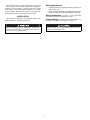
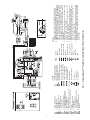
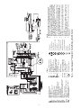
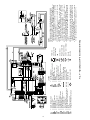
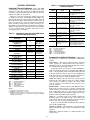
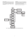
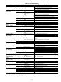
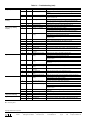
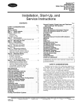
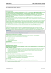
AQUAZONE™ 50RHC,RVC,RHR,RVR
RDS,RHS,RVS,HQL,VQL,KQL,RTG,RWS
Complete C
Deluxe D
Solid-State Heat Pump Controls
Control Operation and Troubleshooting
Instructions
CONTENTS
Page
SAFETY CONSIDERATIONS . . . . . . . . . . . . . . . . . . . . . . . . . . . .1
GENERAL . . . . . . . . . . . . . . . . . . . . . . . . . . . . . . . . . . . . . . . . . . . . 1,2
INSTALLATION . . . . . . . . . . . . . . . . . . . . . . . . . . . . . . . . . . . . . . . 2-9
Wiring Requirements . . . . . . . . . . . . . . . . . . . . . . . . . . . . . . . . . . .2
Wiring Connections . . . . . . . . . . . . . . . . . . . . . . . . . . . . . . . . . . . .2
Jumper Settings . . . . . . . . . . . . . . . . . . . . . . . . . . . . . . . . . . . . . . . .2
Complete C Control. . . . . . . . . . . . . . . . . . . . . . . . . . . . . . . . . . . . .8
• WATER COIL FREEZE PROTECTION (FP1) LIMIT
SETTING
• AIR COIL FREEZE PROTECTION (FP2) LIMIT SETTING
• ALARM RELAY SETTING
Deluxe D Control . . . . . . . . . . . . . . . . . . . . . . . . . . . . . . . . . . . . . . .8
• WATER COIL FREEZE PROTECTION (FP1) LIMIT
SETTING
• AIR COIL FREEZE PROTECTION (FP2) LIMIT SETTING
• ALARM RELAY SETTING
• LOW PRESSURE SETTING
CONFIGURATION . . . . . . . . . . . . . . . . . . . . . . . . . . . . . . . . . . . . 9,10
Complete C Control DIP Switches . . . . . . . . . . . . . . . . . . . . . .9
• PERFORMANCE MONITOR (PM)
• STAGE 2
• DDC OUTPUT AT EH2
• FACTORY SETTING
Deluxe D Control DIP Switches . . . . . . . . . . . . . . . . . . . . . . . . .9
• DIP SWITCH BANK 1 (S1)
• DIP SWITCH BANK 2 (S2)
Deluxe D Control Accessory Relay Configurations . . . .10
• CYCLE WITH FAN
• CYCLE WITH COMPRESSOR
• DIGITAL NIGHT SET BACK (NSB)
• WATER VALVE (Slow Opening)
• OUTSIDE AIR DAMPER (OAD)
• HUMIDITY CONTROL
CONTROL OPERATION . . . . . . . . . . . . . . . . . . . . . . . . . . . . . 11-16
Complete C Control Indicators. . . . . . . . . . . . . . . . . . . . . . . . .11
Complete C and Deluxe D Controls . . . . . . . . . . . . . . . . . . . .11
• TEST MODE
• RETRY MODE
• POWER UP MODE
• STANDBY MODE
• COOLING MODE
• HEATING STAGE 1 MODE
• HEATING STAGE 2 MODE
• LOCKOUT MODE
• LOCKOUT WITH EMERGENCY HEAT
• EMERGENCY HEAT MODE
• HIGH-PRESSURE SWITCH (HP)
• LOW-PRESSURE SWITCH (LP)
• WATER COIL FREEZE PROTECTION (FP1)
• AIR COIL FREEZE PROTECTION (FP2)
• CONDENSATE OVERFLOW (CO)
• OVER/UNDER VOLTAGE SHUTDOWN
• PERFORMANCE MONITOR (PM)
• ANTI-SHORT CYCLE PROTECTION
• RANDOM START
• SWAPPED FP1/FP2 THERMISTORS
• SENSORS
Page
Deluxe D Control. . . . . . . . . . . . . . . . . . . . . . . . . . . . . . . . . . . . . . 13
• LED INDICATORS
• EXTENDED COMPRESSOR OPERATION MONITOR
• STANDBY/FAN ONLY MODE
• HEATING STAGE 1 MODE
• HEATING STAGE 2 MODE
• HEATING STAGE 3 MODE
• EMERGENCY HEAT MODE
• COOLING STAGE 1
• COOLING STAGE 2
• NIGHT LOW LIMIT (NLL) STAGED HEATING
Thermostat Inputs . . . . . . . . . . . . . . . . . . . . . . . . . . . . . . . . . . . . 14
• COMPLETE C CONTROL
• DELUXE D CONTROL
• COMMUNICATION PORTS
• MECHANICAL NIGHT SET BACK
TROUBLESHOOTING . . . . . . . . . . . . . . . . . . . . . . . . . . . . . . .16-20
Field Inputs . . . . . . . . . . . . . . . . . . . . . . . . . . . . . . . . . . . . . . . . . . . 16
Sensor Inputs. . . . . . . . . . . . . . . . . . . . . . . . . . . . . . . . . . . . . . . . . 16
Sensor Outputs . . . . . . . . . . . . . . . . . . . . . . . . . . . . . . . . . . . . . . . 17
Test Mode. . . . . . . . . . . . . . . . . . . . . . . . . . . . . . . . . . . . . . . . . . . . . 17
IMPORTANT: Read the entire instruction manual before
starting installation.
SAFETY CONSIDERATIONS
Read and follow manufacturer instructions carefully. Follow all local electrical codes during installation. All wiring
must conform to local and national electrical codes. Improper
wiring or installation may damage sensor.
Understand the signal words DANGER, WARNING, and
CAUTION. These words are used with the safety alert symbol.
DANGER identifies the most serious hazards which will result
in severe personal injury or death. WARNING signifies a hazard which could result in personal injury or death. CAUTION
is used to identify unsafe practices which would result in minor
personal injury or property damage.
GENERAL
Aquazone Complete C and Deluxe D electronic heat pump
controls are durable, microprocessor-based controllers used to
improve the safety and operation of Aquazone water source
heat pumps. The microprocessor board is specifically designed
to protect against building electrical system noise contamination and radio frequency interference.
The Complete C control base model is a low cost, easy to
use control that provides all the necessary features for water
source heat pump safety and operation. The Complete C
control features a light-emitting diode (LED) to indicate high
pressure, low pressure, low voltage, high voltage, air/water
freeze protection, condensate overflow and control status. The
Complete C control is compatible with most heat pump
thermostats, but is not compatible with Heat/Cool thermostats.
Manufacturer reserves the right to discontinue, or change at any time, specifications or designs without notice and without incurring obligations.
PC 111
Catalog No. 535-00058
Printed in U.S.A.
Form 50H,K,R-2T
Pg 1
6-05
Replaces: 50H,K,R-1T
Book 1 4
Tab 5a 5a
Wiring Requirements
The Deluxe D control is an advanced microprocessor-based
control designed for maximum application flexibility. It
includes all of the Complete C control features plus 3 LED
status indicators and several additional features for extensive
system capability. The Deluxe D control is compatible with
heat pump thermostats as well as heat/cool thermostats.
1. All wiring must be in compliance with all applicable local
and national codes.
2. Wiring should be minimum of 24 AWG (American Wire
Gage) wire with epoxy embedded beryllium copper clip.
Wiring Connections — See Fig. 1-5 for typical wiring
INSTALLATION
of Aquazone Complete C and Deluxe D controls.
The Aquazone™ Complete C and Deluxe D controls can be
field configured for customized applications.
Jumper Settings — Jumpers can be clipped on the control board to customize system operation. See Fig. 1-5.
Before performing service or maintenance operations on
the system, turn off main power switches to the unit. Electric shock can cause personal injury.
Jumpers should only be clipped when power to the control board has been turned off.
2
3
AL
BC
BM
BMC
BR
CAP
CB
CC
CCG
CO
DDC
EH
FP1
FP2
GRY
HP
JW
LED
LOC
MV
NEC
ORG
—
—
—
—
—
—
—
—
—
—
—
—
—
—
—
—
—
—
—
—
—
—
PI
P2
RVS
TRANS
TXV
—
—
—
—
—
Circuit Breaker
Condensate Pan
G
LED
Splice Cap
Wire Nut
Thermistor
Low-Pressure Switch
Temperature Switch
Capacitor
Relay Contacts - N.O.
Relay Contacts - N.C.
Solenoid Coil
Ground
Optional
High-Pressure Switch
*
Relay/Contactor Coil
Field Wiring Terminal Block
Field Wiring Terminal Block
Reversing Valve Solenoid
Transformer
Thermostatic Expansion Valve
Factory Low Voltage Wiring
Factory Line Voltage Wiring
Field Low Voltage Wiring
Field Line Voltage Wiring
Printed Circuit Trace
Optional Wiring
NOTES:
1. Compressor and blower motor thermally protected internally.
2. All wiring to the unit must comply with NEC and local codes.
3. 208/230 v transformer will be connected for 208 v operation. For
230 v operation, disconnect RED lead a L1, and attach ORANGE
lead to L1. Insulate open end of RED lead. 220/240 v transformer
will be connected for 220 v operation. For 240 operation, disconnect RED lead at L1, and attach ORANGE lead to L1. Insulate
open end of RED lead. Transformer is energy limiting or may have
circuit breaker.
4. FP1 thermistor provides freeze protection for water. When using
antifreeze solutions, cut JW3 jumper.
5. Factory cut JW1. Dry contact will be available between AL1 and
AL2. 24 v alarm signal shown.
6. Transformer secondary ground via standoffs and screws to control box. (Ground available from top two standoffs as shown.)
7. Blower motor is factory wired for medium speed. For high or low
speed remove BLU wire from fan motor speed tap ‘M’ and connect to ‘H’ for high or ‘L’ for low.
8. Typical heat pump thermostat wiring shown. Refer to thermostat
installation instructions for wiring to the unit. Thermostat wiring
must be ‘Class 1’ and voltage rating equal to or greater than unit
supply voltage.
Fig. 1 — Typical Aquazone™ Complete C Control Wiring with Heat Pump Control
Alarm Relay Contacts
Blower Contactor
Blower Motor
Blower Motor Capacitor
Blower Relay
Compressor Capacitor
Circuit Breaker
Compressor Contactor
Compressor Contactor Ground
Condensate Overflow Sensor
Direct Digital Control
Emergency Heat
Water Coil Freeze Protection Sensor
Air Coil Freeze Protection Sensor
Grey
High-Pressure Switch
Jumper Wire
Light-Emitting Diode
Loss of Charge Pressure Switch
Motorized Valve
National Electrical Code
Orange
LEGEND
7
4
—
—
—
—
—
—
—
—
—
—
—
—
—
—
—
—
Alarm Relay Contacts
Blower Contactor
Blower Motor
Blower Motor Capacitor
Blower Relay
Compressor Capacitor
Circuit Breaker
Compressor Contactor
Compressor Contactor Ground
Condensate Overflow Sensor
Direct Digital Control
Emergency Heat
Water Coil Freeze Protection Sensor
Air Coil Freeze Protection Sensor
Grey
High-Pressure Switch
High (Leaving) Water Temperature
HWTS — Switch
JW1 — Clippable Field Selection Jumper
LED — Light-Emitting Diode
AL
BC
BM
BMC
BR
CAP
CB
CC
CCG
CO
DDC
EH
FP1
FP2
GRY
HP
Splice Cap
Wire Nut
Ground
Low-Pressure Switch
High-Pressure Switch
Temperature Switch
Relay Contacts - N.O.
Solenoid Coil
Relay Contacts - N.C.
Circuit Breaker
Condensate Pan
Thermistor
NOTES:
1. Compressor and blower motor thermally protected internally.
2. All wiring to the unit must comply with NEC and local codes.
3. Transformer is wired to 265 v (BRN) lead for 265/60/1 units, 230 v
(ORG) lead for 220-240/50/1, or 208 v (RED) lead for 208/60/1.
For 230/60/1 switch RED and ORG leads at L1 and insulate RED
lead. Transformer is energy limiting or may have circuit breaker.
4. FP1 thermistor provides freeze protection for water. When using
antifreeze solutions, cut JW3 jumper.
5. Refer to LonWorks® Installation, Application, and Operation manual for control wiring to the unit. Low voltage wiring must be “Class
1” and voltage rated equal or greater than unit supply voltage.
6. Factory cut JW1 jumper. Dry contact will be available between
AL1 and AL2.
7. Transformer secondary ground via Complete C board standoffs
and screws to control box. (Ground available from top two standoffs as shown.)
8. Fan motors factory wired for medium speed. For high or low
speed remove BLU wire from fan motor speed tap ‘M’ and connect to ‘H’ for high or ‘L’ for low.
9. Optional LON wires. Only connect if LON connection is desired at
the wall sensor.
Fig. 2 — Typical Aquazone™ Complete C Control Wiring with LON Control
Relay/Contactor Coil
— Loss of Charge Pressure
Switch
LON
— Local Operating Network
MV
— Motorized Valve
NEC
— National Electrical Code
ORG
— Orange
PI
— Field Wiring Terminal Block
RVS
— Reversing Valve Solenoid
TRANS — Transformer
TXV
— Thermostatic Expansion
Valve
*
Optional Wiring
Field Line Voltage Wiring
Field Low Voltage Wiring
Printed Circuit Trace
Optional Wiring
LOC
LEGEND
5
AL
BC
BM
BMC
BR
CAP
CB
CC
CCG
CO
COM
CR
DDC
EH
FP1
FP2
GRY
HP
HWTS
JW1
—
—
—
—
—
—
—
—
—
—
—
—
—
—
—
—
—
—
—
—
LED
LOC
LWT
MV
NEC
ORG
PI
RVS
SAT
TRANS
TXV
*
Relay/Contactor Coil
Light-Emitting Diode
Loss of Charge Pressure Switch
Leaving Water Temp
Motorized Valve
National Electrical Code
Orange
Field Wiring Terminal Block
Reversing Valve Solenoid
Supply Air Temperature
Transformer
Thermostatic Expansion Valve
Optional wiring
Field Line Voltage Wiring
Field Low Voltage Wiring
Printed Circuit Trace
Optional Wiring
LEGEND
—
—
—
—
—
—
—
—
—
—
—
Splice Cap
Wire Nut
Ground
Low Pressure Switch
High Pressure Switch
Temperature Switch
Relay Contacts - N.O.
Solenoid Coil
Relay Contacts - N.C.
Circuit Breaker
Condensate Pan
Thermistor
NOTES:
1. Compressor and blower motor thermally protected internally.
2. All wiring to the unit must comply with NEC and local codes.
3. Transformer is wired to 265 v (BRN) lead for 265/60/1 units,
230 v (ORG) lead for 220-240/50/1, or 208 v (RED) lead for
208/60/1. For 203/60/1 switch RED and ORG leads at L1 and
insulate RED lead. Transformer is energy limiting or may have circuit breaker.
4. FP1 thermistor provides freeze protection for water. When using
antifreeze solutions, cut JW3 jumper.
5. Refer to PremierLink start-up and configuration instructions for
control wiring to the unit. Low voltage wiring must be “Class 1” and
voltage rated equal or greater than unit supply voltage.
6. 24-v alarm signal shown. For dry alarm contact, cut JW1 jumper
and dry contact will be available between AL1 and AL2.
7. Transformer secondary ground via Complete C board standoffs
and screws to control box. (Ground available from top two standoffs as shown.)
8. Fan motors factory wired for medium speed. For high or low speed
remove BLU wire from fan motor speed tap ‘M’ and connect to ‘H’
for high or ‘L’ for low.
Fig. 3 — Typical Aquazone™ Complete C Control Wiring with PremierLink™ Control
Alarm Relay Contacts
Blower Contactor
Blower Motor
Blower Motor Capacitor
Blower Relay
Compressor Capacitor
Circuit Breaker
Compressor Contactor
Compressor Contactor Ground
Condensate Overflow Sensor
Communication
Cooling Relay
Direct Digital Control
Emergency Heat
Water Coil Freeze Protection Sensor
Air Coil Freeze Protection Sensor
Grey
High-Pressure Switch
High (Leaving) Water Temp Switch
Clippable Field Selection Jumper
6
AL
BC
BM
BMC
BR
CAP
CB
CC
CCG
CCH
CO
DDC
EH
FP1
FP2
GRY
HP
JW1
—
—
—
—
—
—
—
—
—
—
—
—
—
—
—
—
—
—
Alarm Relay Contacts
Blower Contactor
Blower Motor
Blower Motor Capacitor
Blower Relay
Compressor Capacitor
Circuit Breaker
Compressor Contactor
Compressor Contactor Ground
Crankcase Heater
Condensate Overflow Sensor
Direct Digital Control
Emergency Heat
Water Coil Freeze Protection Sensor
Air Coil Freeze Protection Sensor
Grey
High-Pressure Switch
Clippable Field Selection Jumper
LED
LOC
MV
NEC
ORG
PI
RVS
TRANS
TXV
*
—
—
—
—
—
—
—
—
—
G
NOTES:
1. Compressor and blower motor thermally protected internally.
2. All wiring to the unit must comply with NEC and local codes.
Thermistor
3. Transformer is wired to 265 v (BRN) lead for 265/60/1 units, or
208 v (RED) lead for 208/60/1. For 203/60/1 switch RED and ORG
Condensate Pan
leads at L1 and insulate RED lead. Transformer is energy limiting
Circuit Breaker
or may have circuit breaker.
4. FP1 thermistor provides freeze protection for water. When using
LED
antifreeze solutions, cut JW3 jumper.
5. Check installation wiring information for specific thermostat
Solenoid Coil
hookup. Refer to Thermostat Installation instructions for wiring to
the unit. Thermostat wiring must be “Class 1” and voltage rating
Relay Contacts - N.O.
equal to or greater than unit supply voltage.
Temperature Switch
6. 24-v alarm signal shown. For dry alarm contact, cut JW1 jumper
and dry contact will be available between AL1 and AL2.
Switch - Loss of Charge
7. Transformer secondary ground via Deluxe D board standoffs and
screws to control box. (Ground available from top two standoffs as
Ground
shown.)
Wire Nut
8. Blower motor is factory wired for medium and high speeds. For any
other combination of speeds, at the motor attach BLACK wire to
the higher of the two desired speed taps, and the BLUE wire to the
lower of the two desired speed taps.
9. Aquastat is supplied with unit and must be wired in series with the
hot leg to the pump. Aquastat is rated for voltages up to 277 v.
Fig. 4 — Typical Aquazone™ Deluxe D Control Wiring
Relay/Contactor Coil
Light-Emitting Diode
Loss of Charge Pressure Switch
Motorized Valve
National Electrical Code
Orange
Field Wiring Terminal Block
Reversing Valve Solenoid
Transformer
Thermostatic Expansion Valve
Optional wiring
Field Line Voltage Wiring
Field Low Voltage Wiring
Printed Circuit Trace
Optional Wiring
LEGEND
7
JW1
LED
AL
BC
BM
BMC
BR
CAP
CB
CC
CCG
CO
DDC
EH
FP1 & 2
GRY
HP
HWTS
Alarm Relay Contacts
Blower Contactor
Blower Motor
Blower Motor Capacitor
Blower Relay
Compressor Capacitor
Circuit Breaker
Compressor Contactor
Compressor Contactor Ground
Condensate Overflow Sensor
Direct Digital Control
Emergency Heat
Water and Antifreeze Protection
Grey
High-Pressure Switch
High (Leaving) Water Temperature Swtich
— Clippable Field Selection Jumper
— Light-Emitting Diode
—
—
—
—
—
—
—
—
—
—
—
—
—
—
—
—
Thermistor
Relay/Contactor Coil
Loss of Charge Pressure Switch
Motorized Valve
National Electrical Code
Orange
Field Wiring Terminal Block
Reversing Valve Solenoid
Transformer
Thermostatic Expansion Valve
Optional wiring
Field Line Voltage Wiring
Field Low Voltage Wiring
Printed Circuit Trace
Optional Wiring
LEGEND
—
—
—
—
—
—
—
—
Splice Cap
Wire Nut
Ground
Low Pressure Switch
High Pressure Switch
Temperature Switch
Relay Contacts - N.O.
Solenoid Coil
Relay Contacts - N.C.
Circuit Breaker
Condensate Pan
NOTES:
1. Compressor and blower motor thermally protected internally.
2. All wiring to the unit must comply with NEC and local codes.
3. Transformer is wired to 265 v (BRN) lead for 265/60/1 units, 208 v
(RED) lead for 208/60/1. For 230/60/1 switch RED and ORG leads
at L1 and insulate RED lead. Transformer is energy limiting or may
have circuit breaker.
4. FP1 thermistor provides freeze protection for water. When using
antifreeze solutions, cut JW3 jumper.
5. Refer to LonWorks® Installation, Application and Operation Manual for control wiring to the unit. Low voltage wiring must be “Class
1” and voltage rated equal or greater than unit supply voltage.
6. Factory cut JW4 jumper dry contact will be available between AL1
and AL2.
7. Transformer secondary ground via Deluxe D board standoffs and
screws to control box. (Ground available from top two standoffs as
shown.)
8. Blower motor is factory wired for medium and high speeds. For any
other combination of speeds, at the motor attach BLACK wire to
the higher of the two desired speed taps, and the BLUE wire to the
lower of the two desired speed taps.
9. Optional LON wires. Only connect if LON connection is desired at
the wall sensor.
Fig. 5 — Typical Aquazone™ Deluxe D Control Wiring with LON Control
LOC
MV
NEC
ORG
PI
RVS
TRANS
TXV
*
Complete C Control (Fig. 6)
WATER COIL FREEZE PROTECTION (FP1) LIMIT
SETTING — Select jumper 3 (JW3-FP1 Low Temp) to
choose FP1 limit of either 30 F or 10 F. To select 30 F as the
limit, DO NOT clip the jumper. To select 10 F as the limit, clip
the jumper.
AIR COIL FREEZE PROTECTION (FP2) LIMIT SETTING — Select jumper 2 (JW2-FP2 Low Temp) to choose
FP2 limit of either 30 F or 10 F. To select 30 F as the limit, DO
NOT clip the jumper. To select 10 F as the limit, clip the
jumper.
ALARM RELAY SETTING — Select jumper 4 (JW4-AL2
Dry) to either connect alarm relay terminal (AL2) to 24 vac (R)
or to remain as a dry contact (no connection). To connect AL2
to R, DO NOT clip the jumper. To set as dry contact, clip the
jumper.
LOW PRESSURE SETTING — The Deluxe D control can
be configured for Low Pressure Setting (LP). Select jumper 1
(JW1-LP Norm Open) for choosing between low pressure input normally opened or closed. To configure for normally
closed operation, DO NOT clip the jumper. To configure for
normally open operation, clip the jumper.
Turn off unit power and lock out. Electrical shock and personal injury could result.
WATER COIL FREEZE PROTECTION (FP1) LIMIT
SETTING — Select jumper 3 (JW3-FP1 Low Temp) to
choose FP1 limit of either 30 F or 10 F. To select 30 F as the
limit, DO NOT clip the jumper. To select 10 F as the limit, clip
the jumper.
AIR COIL FREEZE PROTECTION (FP2) LIMIT SETTING — Select jumper 2 (JW2-FP2 Low Temp) to choose
FP2 limit of either 30 F or 10 F. To select 30 F as the limit, DO
NOT clip the jumper. To select 10 F as the limit, clip the
jumper.
ALARM RELAY SETTING — Select jumper 1 (JW1-AL2
Dry) to either connect alarm relay terminal (AL2) to 24 vac (R)
or to remain as a dry contact (no connection). To connect AL2
to R, DO NOT clip the jumper. To set as dry contact, clip the
jumper.
Deluxe D Control (Fig. 7)
Turn off unit power and lock out. Electrical shock and personal injury could result.
BR
BRG
CCG
Test
C
CC
UPS:DISABLED/ENABLED
Comp
Relay
STAGE2: 2/1
NOT USED
DDC OUTPUT: DDC/NORMAL
FP I/FP 2 FAULTS: 3/1
SW1
R
JW3
JW2
Off On
HP
HP
LP
LP
FP1
FP1
FP2
FP2
RV
RV
CO
12 CO
FP1 Low Temp
FP2 Low Temp
Y
Field
Thermostat
Connections
Y
W
O
G
R
C
AL1
AL2
A
P1
P2
1
Micro
Processor
Status
LED
JW1- AL2 Dry
P3
1 24Vdc
EH1
4 EH2
Alarm
Relay
CO
Complete C
17B0001N01
Fig. 6 — Complete C Board
8
Factory Low
Voltage Molex
connector for unit
wiring harness
Low Voltage Molex
connector for
electric heat
harness
C
R
C
S
S
C
R
P5
Com2
P4
Com1
Com
P1
Y1
Y2
W1
Fan
FanEnable
Enable
(240Vac)
(240Vac)
N.O.
O/W2
G
Com
Deluxe D 17B0002N01
R
Fan Speed
(240Vac)
C
AL1
N.O.
N.C.
P2
AL2
R
NSB
Alarm
Relay
JW4
AL2 Dry
C
Micro
U2
1
Test
ESD
OVR
H
Fault
A
RV
Relay
Micro
U1
P3
R
Test Jumpers
NO2
Facttory Use
R
1 24Vdc
JW3 - FP1 Low Temp
JW2 - FP2 Low Temp
EH1
JW1 - LP Norm. Open 4 EH2
COM
NC2
Low voltage
molex connection
for wiring unit
harness
P7
NO1
NC1
COM
HP
HP
LP
LP
FP1
FP1
FP2
FP2
RV
RV
CO
12 CO
Status
Acc1
Relay
P6
Comp
Relay
Acc2
Relay
Low voltage molex
connection for
electric heat
harness
CCG
CC
Fig. 7 — Deluxe D Board
CONFIGURATION
Deluxe D Control DIP Switches — The Deluxe D
control has 2 DIP (dual in-line package) switch banks. Each
bank has 8 switches and is labeled either S1 or S2 on the
circuit board. See Fig. 4.
DIP SWITCH BANK 1 (S1) — This set of switches offers
the following options for Deluxe D control configuration:
Performance Monitor (PM) — The PM is a unique feature
that monitors water temperature and will display a warning
when heat pump is beyond typical operating range. Refer to
Control Operation section for detailed information. DIP switch
1 will enable or disable this feature. To enable the PM, set the
switch to ON. To disable the PM, set the switch to OFF.
Compressor Relay Staging Operation — Switch 2 will enable or disable compressor relay staging operation. The compressor relay can be set to turn on with stage 1 or stage 2 call
from the thermostat. This setting is used with dual stage units
(units with 2 compressors and 2 Deluxe D controls) or in
master/slave applications. In master/slave applications, each
compressor and fan will stage according to its switch 2 setting.
If switch is set to stage 2, the compressor will have a 3-second
delay before energizing during stage 2 demand.
NOTE: If DIP switch is set for stage 2, the alarm relay will not
cycle during Test mode.
Heating/Cooling Thermostat Type — Switch 3 provides selection of thermostat type. Heat pump or heat/cool thermostats
can be selected. Select OFF for heat/cool thermostats. When in
heat/cool mode, Y1 is used for cooling stage 1, Y2 is used for
cooling stage 2, W1 is used for heating stage 1 and O/W2 is
used for heating stage 2. Select ON for heat pump thermostats.
In heat pump mode, Y1 used is for compressor stage 1, Y2 is
used for compressor stage 2, W1 is used for heating stage 3 or
emergency heat, and O/W2 is used for reversing valve (heating
or cooling) depending upon switch 4 setting.
Turn off unit power and lock out. Electrical shock and personal injury could result.
Complete C Control DIP Switches — The Complete
C control has one DIP (dual in-line package) switch bank with
five switches labeled SW1. See Fig. 1.
PERFORMANCE MONITOR (PM) — The PM is a unique
feature that monitors water temperature and will display a warning when heat pump is beyond typical operating range. Refer to
Control Operation section for detailed information. DIP switch
1 will enable or disable this feature. To enable the PM, set the
switch to ON. To disable the PM, set the switch to OFF.
STAGE 2 — Switch 2 will enable or disable compressor
delay. Set switch to OFF for stage 2 in which the compressor
will have a 3-second delay before energizing.
NOTE: The alarm relay will not cycle during Test mode if
switch is set to OFF, stage 2.
Switch 3 is not used.
DDC OUTPUT AT EH2 — Switch 4 provides a selection for
DDC (Direct Digital Control) operation. If set to DDC output
at EH2, the EH2 terminal will continuously output the last fault
code of the controller. If the control is set to EH2 Normal, then
EH2 will operate as standard electric heat output. Set the
switch to ON to set the EH2 to normal. Set the switch to OFF
to set the DDC output at EH2.
NOTE: Some Complete C controls may only have a twoposition DIP switch. Clip the jumper in position 4 of SW1 to
select the DDC output at EH2 option.
FACTORY SETTING — Switch 5 is set to ON. Do not change
the switch to OFF unless instructed to do so by the factory.
9
Table 2 — DIP Switch Block S2 —
Accessory 2 Relay Options
O/B Thermostat Type — Switch 4 provides selection for heat
pump O/B thermostats. O is cooling output. B is heating output. Select ON for thermostats with O output. Select OFF for
thermostats with B output.
Dehumidification Fan Mode — Switch 5 provides selection
of normal or dehumidification fan mode. Select OFF for dehumidification mode. The fan speed relay will remain OFF during cooling stage 2. Select ON for normal mode. The fan speed
relay will turn on during cooling stage 2 in normal mode.
Switch 6 — Switch 6 provides selection for DDC operation. If
set to DDC output at EH2, the EH2 terminal will continuously
output the last fault code of the controller. If the control is set to
EH2 normal, then the EH2 will operate as standard electric
heat output. Set the switch to ON to set the EH2 to normal. Set
the switch to OFF to set the DDC output at EH2.
Boilerless Operation — Switch 7 provides selection of boilerless operation and works in conjunction with switch 8. In boilerless operation mode, only the compressor is used for heating
when FP1 is above the boilerless changeover temperature set
by switch 8 below. Select ON for normal operation or select
OFF for boilerless operation.
Boilerless Changeover Temperature — Switch 8 on S1 provides selection of boilerless changeover temperature set point.
Select OFF for set point of 50 F or select ON for set point of
40 F.
If switch 8 is set for 50 F, then the compressor will be used
for heating as long as the FP1 is above 50 F. The compressor
will not be used for heating when the FP1 is below 50 F and the
compressor will operates in emergency heat mode, staging on
EH1 and EH2 to provide heat. If a thermal switch is being used
instead of the FP1 thermistor, only the compressor will be used
for heating mode when the FP1 terminals are closed. If the FP1
terminals are open, the compressor is not used and the control
goes into emergency heat mode.
DIP SWITCH BANK 2 (S2) — This set of DIP switches is
used to configure accessory relay options. See Fig. 4.
Switches 1 to 3 — These DIP switches provide selection of
Accessory 1 relay options. See Table 1 for DIP switch
combinations.
Switches 4 to 6 — These DIP switches provide selection of
Accessory 2 relay options. See Table 2 for DIP switch
combinations.
Auto Dehumidification Mode or High Fan Mode — Switch 7
provides selection of auto dehumidification fan mode or high
fan mode. In auto dehumidification fan mode the fan speed
relay will remain off during cooling stage 2 if terminal H is
active. In high fan mode, the fan enable and fan speed relays will
turn on when terminal H is active. Set the switch to ON for auto
dehumidification fan mode or to OFF for high fan mode.
Factory Setting — Switch 8 is set to ON. Do not change the
switch to OFF unless instructed to do so by the factory.
DIP SWITCH POSITION
4
5
6
On
On
On
Off
On
On
On
Off
On
On
On
Off
ACCESSORY 2
RELAY OPTIONS
Cycle with Compressor
Digital NSB
Water Valve — Slow Opening
OAD
LEGEND
NSB — Night Setback
OAD — Outside Air Damper
NOTE: All other switch combinations are invalid.
Deluxe D Control Accessory Relay Configurations — The following accessory relay settings are applicable for Deluxe D control:
CYCLE WITH FAN — In this configuration, the accessory
relay 1 will be ON any time the Fan Enable relay is on.
CYCLE WITH COMPRESSOR — In this configuration, the
accessory relay 2 will be ON any time the Compressor relay is
on.
DIGITAL NIGHT SET BACK (NSB) — In this configuration, the relay will be ON if the NSB input is connected to
ground C.
NOTE: If there are no relays configured for digital NSB, then
the NSB and OVR inputs are automatically configured for
mechanical operation. See the Mechanical Night Set Back section on page 16.
WATER VALVE (Slow Opening) — If relay is configured for
Water Valve (slow opening), the relay will start 60 seconds
prior to starting compressor relay.
OUTSIDE AIR DAMPER (OAD) — If relay is configured for
OAD, the relay will normally be ON any time the Fan Enable
relay is energized. The relay will not start for 30 minutes following a return to normal mode from NSB, when NSB is no
longer connected to ground C. After 30 minutes, the relay will
start if the Fan Enable is set to ON.
HUMIDITY CONTROL — A separate humidistat will allow
the unit to dehumidify once the heating call is satisfied. Some
integrated thermostats may be reconfigured to allow dehumidification in heating. See Fig. 4 for typical humidistat wiring. See
below for Deluxe D DIP switch settings and reheat logic.
SWITCH BANK 2
REHEAT (ON) REHEAT (OFF)
LOGIC
2.1 2.2 2.3
Terminal H
Terminal H
Humidistat OFF OFF OFF Reverse
0 vac
24 vac
Dehumidistat OFF ON OFF Standard
24 vac
0 vac
SENSOR
Reheat
Humidistat — The humidistat energizes a contact when the
humidity of the space rises or falls. See Table 3. A reheat coil
(water coil located after the evaporator coil) will be modulated
by a motorized valve enabled by the ACC1 relay to bring the
supply air to neutral conditions.
Table 1 — DIP Switch Block S2 —
Accessory 1 Relay Options
Table 3 — Deluxe D Reheat Operating Modes
INPUT*
ACCESSORY 1
RELAY OPTIONS
Cycle with Fan
Digital NSB
Water Valve — Slow Opening
OAD
Reheat — (Fall in Humidity)
Reheat — (Rise in Humidity)
MODE
DIP SWITCH POSITION
1
2
3
On
On
On
Off
On
On
On
Off
On
On
On
Off
Off
Off
Off
Off
On
Off
No Demand
Fan Only
Cooling
Cooling and
Humidistat†
Humidistat
Only
Heating
Heating and
Humidistat
LEGEND
NSB — Night Setback
OAD — Outside Air Damper
OUTPUT
Reheat
Mode
ON/OFF OFF OFF OFF ON/OFF OFF OFF OFF
ON/OFF ON OFF OFF ON/OFF ON OFF OFF
ON
ON ON OFF
ON
ON ON
OFF
O
G
Y1
H
O
G
Y1
ON
ON
ON
ON
ON
ON
ON
OFF
ON/OFF OFF OFF ON
ON
ON
ON
ON
OFF
ON
ON OFF
OFF
ON
ON
OFF
OFF
ON
ON
OFF
ON
ON
OFF
ON
*Reheat mode may be controlled with a humidistat configured for a rise or fall
in humidity.
†Cooling input takes priority over dehumidify input.
**Deluxe D is programmed to ignore the H demand when the unit is in Heating
mode.
NOTE: All other DIP switch combinations are invalid.
10
Table 5 — Complete C Control LED Code and
Fault Descriptions
CONTROL OPERATION
Complete C Control Indicators — The status LED
on the Complete C control displays the current status of the
Complete C control. If in Test mode, the LED will flash the
code of the last fault and the alarm relay will cycle the same
number as the fault code. See Table 4.
There are 2 categories of fault types: primary and secondary. Primary fault types include High Pressure (HP), Low
Pressure (LP), Water Coil Freeze Protection (FP1), Air Coil
Freeze Protection (FP2), and Condensate Overflow (CO). If
fault type is primary, it is always stored in memory. Primary
faults override secondary faults. Secondary fault types are:
Over/Under Voltage Shutdown and Performance Monitor
(PM). Secondary faults are retained in memory only if there
are not any primary faults. Secondary faults will not overwrite primary faults. See Table 5.
LED
CODE
1
LED STATUS
ALARM RELAY
Normal Mode with
PM Warning
On
Open
Cycle
(closed 5 sec.,
Open 25 sec.)
Complete C Control is
non-functional
Fault Retry
Lockout
Off
Open
Slow Flash
Fast Flash
Open
Closed
Open
(Closed after
15 minutes)
Over/Under Voltage
Shutdown
Test Mode —
No Fault in Memory
Test Mode —
HP Fault in Memory
Test Mode —
LP Fault in Memory
Test Mode —
FP1 Fault in Memory
Test Mode —
FP2 Fault in Memory
Test Mode —
CO Fault in Memory
Test Mode — Over/Under
Shutdown in Memory
Test Mode — PM in Memory
Test Mode — FP1/FP2
Swapped Fault in Memory
CO
FP
HP
LED
LP
PM
—
—
—
—
—
—
Slow Flash
Flashing Code 1
Cycling Code 1
Flashing Code 2
Cycling Code 2
Flashing Code 3
Cycling Code 3
Flashing Code 4
Cycling Code 4
Flashing Code 5
Cycling Code 5
Flashing Code 6
Cycling Code 6
Flashing Code 7
Cycling Code 7
Flashing Code 8
Cycling Code 8
Flashing Code 9
Cycling Code 9
DESCRIPTION
There has been no fault since
the last power-down to powerup sequence
2
High-Pressure Switch
HP Open Instantly
3
Low-Pressure Switch or LP open for 30 continuous secLOC
onds before or during a call
(bypassed for first 120 seconds
of operation)
4
Freeze Protection Coax FP1 below Temp limit for 30
— FP1
continuous seconds (bypassed
for first 120 seconds of
operation)
5
Freeze Protection Air
FP2 below Temp limit for 30
Coil — FP2
continuous seconds (bypassed
for first 120 seconds of
operation)
6
Condensate overflow
Sense overflow (grounded) for
30 continuous seconds
7
Over/Under Voltage
"R" power supply is <8 vac or
(Autoreset) Shutdown
>365 vac
8
PM Warning
Performance Monitor Warning
has occurred.
9
FP1 and FP2 TherFP1 temperature is higher than
mistors are in Reverse FP2 in Heating/Test mode, or
Positions
FP2 temperature is higher than
FP1 in Cooling test mode.
Table 4 — Complete C Control Current LED Status
and Alarm Relay Operations
DESCRIPTION OF
OPERATION
Normal Mode
FAULT
CO
FP
HP
LED
LOC
PM
—
—
—
—
—
—
No fault in memory
LEGEND
Condensate Overflow
Freeze Protection
High Pressure
Light-Emitting Diode
Loss of Charge Switch
Performance Monitor
Complete C and Deluxe D Controls — The following operations are common to both Complete C and Deluxe D
controls.
TEST MODE — Test mode provides the ability to check the
control operation in a timely manner. The control enters a
20-minute Test mode by momentarily shorting the test terminals. All time delays are sped up 15 times.
To enter Test mode, cycle the power 3 times within 60 seconds or monentarily short the test terminals. The LED will
flash a code representing the last fault when entering the Test
mode. The alarm relay will also power on and off during Test
mode. See Table 3. To exit Test mode, short the terminals for 3
seconds or cycle the power 3 times within 60 seconds.
NOTE: The flashing code and alarm relay cycling code will
both have the same numerical label. For example, flashing
code 1 will have an alarm relay cycling code 1. Code 1 indicates the control has not faulted since the last power off to
power on sequence.
RETRY MODE — In retry mode, the status LED will start to
flash slowly (one flash every two seconds) to signal that the
control is trying to recover from an input fault. The control will
stage off the outputs and try to again satisfy the thermostat
used to terminal Y. Once the thermostat input calls are satisfied, the control will continue normal operation.
NOTE: If 3 consecutive faults occur without satisfying the
thermostat input call to terminal Y, the control will go into
lockout mode. The last fault causing the lockout is stored in
memory and can be viewed by entering Test mode.
If one try is selected for FP1 and FP2 then there will be no
retries for FP1 and FP2 faults.
POWER UP MODE — The unit will not operate until all the
inputs, terminals and safety controls are checked for normal
operation.
NOTE: The compressor will have a 5 minute anti-short cycle
upon power up.
LEGEND
Condensate Overflow
Freeze Protection
High Pressure
Light-Emitting Diode
Low Pressure
Performance Monitor
NOTES:
1. Slow flash is 1 flash every 2 seconds.
2. Fast flash is 2 flashes every 1 second.
3. EXAMPLE: “Flashing Code 2” is represented by 2 fast flashes followed by a 10-second pause. This sequence will repeat continually
until the fault is cleared.
11
than 2° F per 30 continuous seconds during a compressor run
cycle to be recognized as a FP2 fault. The FP2 input is
bypassed for the first 120 seconds of compressor run cycle.
The FP2 lockout code 5 on the LED will appear as 5 fast
flashes alternating with a 10-second pause.
CONDENSATE OVERFLOW (CO) — Condensate overflow
sensor must sense overflow levels for 30 continuous seconds
during a compressor run cycle to be recognized as a CO fault.
The CO lockout code 6 on the LED will appear as 6 fast
flashes alternating with a 10-second pause.
OVER/UNDER VOLTAGE SHUTDOWN — An over/under
voltage shutdown condition exists when the control voltage is
NOT in the range of 18 vac to 31.5 vac. The control will
automatically be reset and normal operation will resume if the
voltage comes back within at least 0.5 volts of the minimum
and maximum voltage range (18.5 to 31 vac) for at least
0.5 seconds. This case is not considered a fault or lockout. If
the control is in over/under voltage shutdown for 15 minutes,
the alarm relay will close. The over/under voltage shutdown
code 7 on the LED will appear as 7 fast flashes alternating with
a 10-second pause.
PERFORMANCE MONITOR (PM) — The Performance
Monitor displays a warning when the heat pump is operating
inefficiently. The control will immediately generate a PM
warning if any of the following conditions exist:
• FP2 is greater than 125 F for more than 30 continuous
seconds in Heating mode with compressor energized.
• FP1 is greater than 125 F for more than 30 continuous
seconds in Cooling mode with compressor energized.
• FP2 is less than 40 F for more than 30 continuous seconds in Cooling mode with compressor energized.
The status LED light will remain on as if control is in normal mode. Outputs of the control, excluding the LED and
alarm relay, will not be affected by PM warning. A PM warning cannot happen during a compressor off cycle. During the
PM warning, the alarm relay will cycle on and off. The cycle
rate will continuously alternate on for 5 seconds and off for
25 seconds. PM warning code 8 on the LED will appear as
8 fast flashes alternating with a 10-second pause.
ANTI-SHORT CYCLE PROTECTION — The control features a 5-minute time delay from the last start before energizing
the compressor again.
NOTE: The 5-minute anti-short cycle occurs at every power up.
RANDOM START — The random start control features five
80-second random start upon power up. The random start delay
will be present in Deluxe D control after a control power up and
after returning from Night Setback or Emergency Shutdown
modes.
SWAPPED FP1/FP2 THERMISTORS — During Test mode,
the control monitors to see if the FP1 and FP2 thermistors are
wired to the appropriate place. If the control is in Test mode,
the control will lock out, with code 9, after 30 seconds if:
• The compressor is on and in cooling mode and the FP1
sensor is colder than the FP2 sensor.
• The compressor is on and in heating mode and the FP2
sensor is colder than the FP1 sensor.
SENSORS
Thermistor — The thermistor is negative temperature coefficient (NTC) type and the sensor has a 1% calibration tolerance.
See Fig. 8 and Table 6.
Condensate Sensor — The condensate sensor input will fault
upon sensing impedance less than 100,000 ohms for 30 continuous seconds. The recommended design uses a single wire
terminated with a male 1/4 in. quick connect located in the
drain pan at the desired trip level. Upon a high condensate
level the water will short between the air coil and the quick
connect producing a resistance less than 100,000 ohms. Since
condensate is free of impurities, it has no conductivity. Only
STANDBY MODE — The Y and W terminals are not active
in Standby mode, however the O and G terminals may be
active, depending on the application. The compressor will be
off.
COOLING MODE — The Y and O terminals are active in
cooling mode. After power up, the first call to the compressor
will initiate a 5 to 80 second random start delay and a 5-minute
anti-short cycle protection time delay. After both delays are
complete, the compressor is energized.
NOTE: On all subsequent compressor calls the random start
delay is omitted.
HEATING STAGE 1 MODE — Terminal Y is active in heating stage 1. After power up, the first call to the compressor will
initiate a 5 to 80 second random start delay and a 5-minute
anti-short cycle protection time delay. After both delays are
complete, the compressor is energized.
NOTE: On all subsequent compressor calls the random start
delay is omitted.
HEATING STAGE 2 MODE — To enter stage 2 mode, terminal W is active (Y is already active). Also, the G terminal must
be active or the W terminal is disregarded. The compressor
relay will remain on and EH1 is immediately turned on. EH2
will turn on after 10 minutes of continual stage 2 demand.
NOTE: EH2 will not turn on (or if on, will turn off) if FP1 temperature is greater than 45 F and FP2 is greater than 110 F.
LOCKOUT MODE — The status LED will flash fast in lockout mode and the compressor relay will be turned off immediately. Lockout mode can be “soft” reset via the Y input or can
be “hard” reset via the disconnect. The last fault causing the
lockout is stored in memory and can be viewed by entering test
mode.
LOCKOUT WITH EMERGENCY HEAT — While in Lockout mode, if W becomes active, then Emergency Heat mode
will occur.
EMERGENCY HEAT MODE — In Emergency Heat mode,
terminal W is active while terminal Y is not. Terminal G must
be active or the W terminal is disregarded. EH1 is immediately
turned on. EH2 will turn on after 5 minutes of continual emergency heat demand.
NOTE: The FP1 and FP2 temperatures do not effect emergency heat operation.
HIGH-PRESSURE SWITCH (HP) — In the event of high
refrigerant pressures, the high-pressure switch will open. The
compressor relay is deenergized immediately because the
high-pressure switch is in series with the compressor contactor
coil. The high-pressure fault is recognized immediately. The
high pressure lockout code 2 on the LED will appear as 2 fast
flashes alternating with a 10-second pause.
LOW-PRESSURE SWITCH (LP) — If the low-pressure
switch is open for 30 seconds prior to compressor power up, or
is open and remains open for 30 continuous seconds during the
“on” cycle, it is considered to be a low pressure (loss of
charge) fault. The low-pressure switch input is bypassed for
the first 120 seconds of compressor run cycle. The low pressure lockout code 3 on the LED will appear as 3 fast flashes
alternating with a 10-second pause.
WATER COIL FREEZE PROTECTION (FP1) — The FP1
thermistor must be below the selected freeze protection limit
setting and the measured temperature is rising at a rate of less
than 2° F per 30 continuous seconds during a compressor run
cycle to be recognized as a FP1 fault. The FP1 input is
bypassed for the first 120 seconds of compressor run cycle.
The FP1 lockout code 4 on the LED will appear as 4 fast
flashes alternating with a 10-second pause.
AIR COIL FREEZE PROTECTION (FP2) — The FP2 thermistor must be below the selected freeze protection limit setting and the measured temperature is rising at a rate of less
12
the impurities from the drain pan and coil dust or dirt create the
conductance. A second ground wire with appropriate terminal
to the drain pan can be used with the control to replace the air
coil ground path. The condensate sensor can also be any open
contact that closes upon a fault connection.
90.0
80.0
70.0
TEMP (F)
78.5
77.5
76.5
75.5
33.5
32.5
31.5
30.5
1.5
0.5
0.0
MINIMUM
RESISTANCE
(ohm)
9,523
9,650
10,035
10,282
30,975
31,871
32,653
33,728
80,624
83,327
84,564
MAXIMUM
RESISTANCE
(ohm)
9,715
9,843
10,236
10,489
31,598
32,512
33,310
34,406
82,244
85,002
86,264
Resistance (kOhm)
Table 6 — Thermistor Calibration Points
NOMINAL
RESISTANCE
(ohm)
9,619
9,746
10,135
10,385
31,285
32,190
32,980
34,065
81,430
84,160
85,410
60.0
50.0
40.0
30.0
20.0
10.0
0.0
0.0
20.0
40.0
60.0
80.0
100.0
120.0
140.0
Temperature (degF)
Fig. 8 — Thermistor Nominal Resistance
Deluxe D Control — The Deluxe D control includes all
EXTENDED COMPRESSOR OPERATION MONITOR —
If the compressor has been on for 4 continuous hours the control will automatically turn off the compressor relay and wait
the short cycle time protection time. All appropriate safeties
including the low-pressure switch will be monitored. If all
operations are normal, and the compressor demand is still
present, the control will turn the compressor back on.
STANDBY/FAN ONLY MODE — The compressor will be
off. The fan enable, fan speed, and reversing valve (RV) relays
will be on if inputs are present. If there is a fan 1 demand, the
fan enable will immediately turn on. If there is a fan 2 demand,
the fan enable and fan speed relays will immediately turn on.
NOTE: DIP switch 5 on S1 (dehumidification fan mode select)
does not have an effect upon fan 1 and fan 2 outputs.
of the control operations above in addition to the following
advanced operations:
LED INDICATORS — There are 3 LED indicators on the
Deluxe D control. See Table 7 for indicators.
Status LED — Status LED indicates the current status or mode
of the Deluxe D control. The status LED light is green.
Test LED — Test LED will be activated any time the Deluxe
D control is in Test mode. The test LED light is yellow.
Fault LED — Fault LED light is red. The fault LED will always flash a code representing the last fault in memory. If there
is no fault in memory, the fault LED will flash code 1 on the
and appear as 1 fast flash alternating with a 10-second pause.
See Table 7.
Table 7 — Aquazone™ Deluxe D Control Current LED Status and Alarm Relay Operations
Normal Mode
STATUS LED
(Green)
On
TEST LED
(Yellow)
Off
FAULT LED
(Red)
Flash Last Fault Code in Memory
Normal Mode with PM
On
Off
Flashing Code 8
Open
Cycle (closed 5 sec,
open 25 sec, …)
Off
Off
Off
Open
—
Flashing Code 2
Flashing Code 3
Flashing Code 4
On
Slow Flash
Slow Flash
Slow Flash
Slow Flash
Slow Flash
Slow Flash
Fast Flash
Fast Flash
Fast Flash
Fast Flash
Fast Flash
Fast Flash
On
—
—
—
Off
Off
Off
Off
Off
Off
Off
Off
Off
Off
Off
Off
Off
Flash Last Fault Code in Memory
Flash Last Fault Code in Memory
Flash Last Fault Code in Memory
Flash Last Fault Code in Memory
Flashing Code 1
Flashing Code 2
Flashing Code 3
Flashing Code 4
Flashing Code 5
Flashing Code 6
Flashing Code 7
Flashing Code 2
Flashing Code 3
Flashing Code 4
Flashing Code 5
Flashing Code 6
Flashing Code 9
Cycling Appropriate Code
—
—
—
Open
Open
Open
Open
Open
Open
Open (closed after 15 minutes)
Closed
Closed
Closed
Closed
Closed
Closed
DESCRIPTION
Deluxe D Control
is Non-Functional
Test Mode
Night Setback
ESD
Invalid Thermostat Inputs
No Fault in Memory
HP Fault
LP Fault
FP1 Fault
FP2 Fault
CO Fault
Over/Under Voltage
HP Lockout
LP Lockout
FP1 Lockout
FP2 Lockout
CO Lockout
Swapped FP1/FP2
CO
ESD
FP
HP
LP
PM
—
—
—
—
—
—
LEGEND
Condensate Overflow
Emergency Shutdown
Freeze Protection
High Pressure
Low Pressure
Performance Monitor
ALARM RELAY
NOTES:
1. If there is no fault in memory, the Fault LED will flash code 1.
2. Codes will be displayed with a 10-second Fault LED pause.
3. Slow flash is 1 flash every 2 seconds.
4. Fast flash is 2 flashes every 1 second.
5. EXAMPLE: “Flashing Code 2” is represented by 2 fast flashes followed by a 10-second pause. This sequence will repeat continually
until the fault is cleared.
13
Thermostat Inputs
HEATING STAGE 1 MODE — In Heating Stage 1 mode, the
fan enable and compressor relays are turned on immediately.
Once the demand is removed, the relays are turned off and the
control reverts to Standby mode. If there is a master/slave or
dual compressor application, all compressor relays and related
functions will operate per their associated DIP switch 2 setting
on S1.
HEATING STAGE 2 MODE — In Heating Stage 2 mode, the
Fan Enable and Compressor relays remain on. The fan speed
relay is turned on immediately and is turned off immediately
once the demand is removed. The control reverts to Heating
Stage 1 mode. If there is a master/slave or dual compressor
application, all compressor relays and related functions will
operate per their associated DIP switch 2 setting on S1. If configured as Stage 2 (DIP switch S1 position 2 is set to OFF)
then the compressor and fan will not turn until there is a call
for Stage 2.
HEATING STAGE 3 MODE — In Heating Stage 3 mode, the
fan enable, fan speed and compressor relays will remain on.
The EH1 output is turned on immediately. With continuing
Heat Stage 3 demand, EH2 will turn on after 10 minutes. The
EH1 and EH2 output signals are turned off immediately when
the Heating Stage 3 demand is removed. The control reverts to
Heating Stage 2 mode.
The EH2 output signal will be off if FP1 is greater than
45 F AND FP2 (when shorted) is greater than 110 F during
Heating Stage 3 mode. This condition will have a 30-second
recognition time. Also, during Heating Stage 3 mode, EH1,
EH2, fan enable, and fan speed will be ON if G input is not
active.
EMERGENCY HEAT MODE — In Emergency Heat mode,
the fan enable and fan speed relays are turned on. The EH1
output is turned on immediately. With continuing Emergency
Heat demand, EH2 will turn on after 5 minutes. Fan enable and
fan speed relays are turned off after a 60-second delay. The
control reverts to Standby mode.
The EH1, EH2, fan enable, and fan speed signals will be
ON if the G input is not active during Emergency Heat mode.
COOLING STAGE 1 — In Cooling Stage 1 mode, the fan
enable, compressor and RV relays are turned on immediately.
If configured as stage 2 (DIP switch S1 position 2 set to OFF)
then the compressor and fan will not turn on until there is a
stage 2 demand. The fan enable and compressor relays are
turned off immediately when the Cooling Stage 1 demand is
removed. The control reverts to Standby mode. The RV relay
remains on until there is a heating demand. If there is a master/
slave or dual compressor application, all compressor relays and
related functions will track with their associated DIP switch 2
on S1.
COOLING STAGE 2 — In Cooling Stage 2 mode, the fan
enable, compressor and RV relays remain on. The fan speed
relay is turned off immediately once the Cooling Stage 2
demand is removed. The control reverts to Cooling Stage 1
mode. If there is a master/slave or dual compressor application,
all compressor relays and related functions will track with their
associated DIP switch 2 on S1.
NIGHT LOW LIMIT (NLL) STAGED HEATING — In NLL
staged Heating mode, the override (OVR) input becomes
active and is recognized as a call for heating and the control
will immediately go into a Heating Stage 1 mode. With an
additional 30 minutes of NLL demand, the control will go into
Heating Stage 2 mode. With another additional 30 minutes of
NLL demand, the control will go into Heating Stage 3 mode.
COMPLETE C CONTROL
Y and W Terminals — Terminals Y and W have 1-second
recognition time when being activated or removed.
O and G Terminals — Terminals O and G are direct pass
through signals monitored by the microprocessor.
R and C Terminals — Terminals R and C originate from the
transformer.
AL1 and AL2 Terminals — Terminals AL1 and AL2 originate from alarm relay.
Terminal A — Terminal A is paralleled with compressor output for use with well water solenoid valves.
Y 1/4 in. Quick Connect — The Y 1/4 in. quick connect is for
factory use. It is used for panel mount relays such as loop pump
relay.
DELUXE D CONTROL (see Tables 8-10)
Y1 — Terminal Y1 is input for compressor stage 1 if DIP
switch 3 on S1 is set to ON. If DIP switch is set to OFF, then
Y1 is input for Cooling Stage 1.
Y2 — Terminal Y2 is input for compressor stage 2 if DIP
switch 3 on S1 is set to ON. If DIP switch is set to OFF, then
Y2 is input for Cooling Stage 1.
W1 — If terminals Y1 and Y2 are active and DIP switch 3 on
S1 is set to ON, then W1 is input for Heating Stage 3. If Y1 and
Y2 are NOT active and DIP switch is set to ON, then W1 is
input for Emergency Heat mode. If DIP switch is set to OFF,
then W1 is input for Heating Stage 1 mode.
O/W2 — If DIP switches 3 and 4 on S1 are set to ON, terminal
O/W2 will be input for Reversing Valve (RV) relay. If DIP
switch 3 is OFF and DIP switch 4 is ON, O/W2 will be the
input for Heating Stage 2 mode.
If DIP switch 3 is ON and DIP switch 4 is OFF, O/W2 will
be the input for Heat mode. In this mode, the thermostat outputs a B call when in Heating mode and does not have an
O output. The D control will employ RV control. This ensures
RV will only switch positions if the thermostat has a call for
heating/cooling mode change.
R and C Terminals — Terminals R and C originate from the
transformer.
AL1 and AL2 Terminals — Terminals AL1 and AL2 originate from alarm relay.
G — Input for fan enable relay.
NSB and Override — When digital NSB is selected via the
accessory relay DIP switch and the NSB input is connected to
ground C, the appropriate accessory relay directly tracks the
NSB input.
When digital NSB is NOT selected via the accessory relay
DIP switch and the NSB input is NOT connected to ground C,
then all thermostat inputs are ignored. During this time period,
if OVR is momentarily connected to 24 vac, then the thermostat outputs are once again monitored for 2 hours. After the
2-hour override period, the Deluxe D control will assume NSB
is again connected to ground C and the control will revert back
to ignoring the thermostat inputs. There will be a random start
timer when coming back from NSB mode.
A maximum of 75 Deluxe D controllers can be
daisy-chained to the NSB terminals. The maximum total wire
resistance is 500 ohms.
14
Table 8 — Deluxe D Control System Inputs
UNIT OPERATING
MODE*
Emergency
Shut Down
(ESD)
X
ANY
ALL (EXCEPT INVALID)
OFF
SYSTEM INPUTS
Night
Setback
(NSB)
ANY
OFF
OFF
X
X
X
Override
(OVR)
NIGHT SETBACK
TYPE
(NSB)
ANY
OFF
M
OFF
M
OFF
NONE
NONE
NONE
DIGITAL
DIGITAL
MECHANICAL
X
M
MECHANICAL
OFF
X
X
OFF
X
X
X
X
X
X
X
X
NONE
MECHANICAL
DIGITAL
NONE
MECHANICAL
DIGITAL
UNIT OPERATION
IMPACTS
UNIT SHUT DOWN
NORMAL OPERATION
STANDBY / OFF
NORMAL FOR 2 HRS THEN
RETURN TO STANDBY
C1, C2
OFF
EH
OFF
INVALID — UNIT
WILL NOT OPERATE
OFF
ANY
ANY
NONE
UNIT WILL NOT OPERATE
OFF, F, H1,H2 OR H3
OFF
OFF
X
X
X
X
X
NONE
MECHANICAL
DIGITAL
NLL STAGED HEATING
C1
C2
EH
F
H1
H2
—
—
—
—
—
—
Cooling Stage 1
Cooling Stage 2
Emergency Heat
Fan
Heat Stage 1
Heat Stage 2
LEGEND
H3
M
NLL
RVR
X
INVALID
EH — NO CHANGE
*See Table 8 for additional operating mode information.
—
—
—
—
—
Heat Stage 3
Momentary Input
Night Low Limit
Reversing Valve
Continuous Input
Table 9 — Deluxe D Control — Input Combinations — DIP Switch Block 1 (S1)
UNIT OPERATION
Mode
(OFF)
(FAN)
Operation
STANDBY / OFF
FAN OPERATION ONLY
(C1)
COOLING 1– FAN ENABLE / RVR – NO FAN OR COMPRESSOR
(C2)
COOLING 2– FAN / COMPRESSOR 1 / RVR
(H1)
HEATING 1– FAN ENABLE – NO FAN OR COMPRESSOR
(H2)
HEATING 2– FAN / COMPRESSOR 1
(H3)
HEATING 3– FAN / COMPRESSOR*/ELECTRIC HEAT
(EH)
HEATING – FAN / EMERGENCY ELECTRIC HEAT
—
Unit will not operate
C1 — Cooling Stage 1
C2 — Cooling Stage 2
EH — Emergency Heat
LEGEND
H1
H2
H3
THERMOSTAT CONNECTIONS
ENERGIZED
G
Y1
Y2
W1
O/W2
—
—
—
—
—
X
—
—
—
—
—
X
—
—
X
—
X
—
—
—
—
X
—
—
—
—
—
X
—
X
—
—
X
—
—
—
—
X
—
—
—
X
—
—
—
—
X
—
—
X
—
—
—
X
—
—
—
X
—
—
—
—
X
—
X
—
—
—
—
X
—
X
—
X
—
—
X
—
X
X
—
—
—
X
—
—
—
—
X
—
—
—
—
X
X
—
X
—
X
—
—
X
—
—
X
—
—
X
X
—
—
—
X
—
X
—
X
X
X
—
SWITCH 1
SETTING
DIP 3 DIP 4
ANY
ANY
ANY
ANY
ON
ON
ON
OFF
OFF
ANY
ON
ON
ON
OFF
OFF
ANY
ON
ON
ON
OFF
OFF
ANY
ON
ON
ON
OFF
OFF
ANY
ON
ON
ON
OFF
ON
ON
ON
OFF
ON
ON
OFF
ANY
OFF
ANY
OFF
ANY
OFF
ANY
ON
OFF
NOTE: Input combinations are on S1 with DIP Switch 2 set for “off”
position for all combinations.
— Heat Stage 1
— Heat Stage 2
— Heat Stage 3
*Compressor no. 1 if energized.
15
Table 10 — Deluxe D Control — Input Combinations — DIP Switch Block 2 (S2)
UNIT
OPERATING MODE*
SIGNAL ON
H
STANDBY / OFF
ENERGIZED
FAN 1 SIGNAL
ENERGIZED
COOLING 1 SIGNAL
ENERGIZED
COOLING 2 SIGNAL
ENERGIZED
HEATING 1 SIGNAL
ENERGIZED
HEATING 2 SIGNAL
HEATING 3 SIGNAL
EMERGENCY HEAT
INVALID
ENERGIZED
ENERGIZED
ENERGIZED
ANY
SWITCH 2 DIP 7
UNIT OPERATION IMPACT
ON
OFF
ON
OFF
ON
OFF
ON
OFF
ON
OFF
ANY
ANY
ANY
ANY
STANDBY / OFF WITH AUTO. DEHUMIDIFICATION
FAN HIGH
FAN LOW WITH AUTO. DEHUMIDIFICATION
FAN HIGH
COOLING WITH FAN LOW†
COOLING WITH FAN HIGH†
COOLING WITH FAN LOW†
COOLING WITH FAN HIGH†
HEATING WITH FAN LOW†
HEATING WITH FAN HIGH†
HEATING WITH FAN HIGH
HEATING WITH FAN HIGH
EMERGENCY HEAT WITH FAN HIGH
INVALID
LEGEND
H — Automatic Dehumidification
NOTE: Input combinations are on S2 with DIP switch 7 and input “H”
for automatic dehumidification.
*See Table 8 for additional operation information.
†These results will vary depending on the configuration of DIP
Switch 2 on S1.
NOTE: Each heat pump has the ability to be a dual compressor
unit allowing up to 6 Deluxe D controls to be controlled by one
thermostat. Only one Deluxe D control in each heat pump will
be daisy chained on COM1.
COM2 — COM2 has the ability to communicate thermostat
and external calls to a second Deluxe D control being used for
dual compressor function. A heat pump with 2 compressors
will have one Deluxe D control for each compressor. The
master Deluxe D control will handle all input and output
commands with external sources, monitor and control all
operations of the secondary Deluxe D control. The secondary
Deluxe D control does not have any direct connection to
exterior devices.
Since the master and slave Deluxe D controls share sensor
and water valve/pump restart operations they also share
signals. Both Deluxe D controls will fault or go into lockout
mode if either the master or slave Deluxe D control senses a
CO fault. In either mode, the Deluxe D control will continue to
provide water valve/pump restart operation for the other functioning Deluxe D control.
MECHANICAL NIGHT SET BACK — When NSB input is
connected to ground C, all thermostat inputs are ignored. A
thermostat set back heating call will then be connected to the
OVR input. If OVR input becomes active, then the Deluxe D
control will enter night low limit (NLL) staged heating mode.
The NLL staged heating mode will then provide heating
during the NSB period.
ESD (Input for Emergency Shutdown mode) — When ESD
is connected to ground C, all thermostat inputs are ignored and
all outputs are turned off. There will be a random start timer
when coming back from ESD mode.
A maximum of 75 Deluxe D controllers can be
daisy-chained to the ESD terminals. The maximum total wire
resistance is 500 ohms.
OVR (Input for Night Set Back Override or Night Low
Limit Staged Heating input) — If digital NSB is NOT selected via accessory relay DIP switch inputs but is connected to
ground C and OVR is momentarily connected to 24 vac for at
least 1 second, then the OVR input is recognized as a NSB
signal. The Deluxe D control reverts from NSB and begins to
monitor thermostat inputs for heating and cooling calls for a
2-hour override period. If NSB is connected to ground C and if
OVR is continuously connected to 24 vac, then the OVR input
is recognized as a call for NLL Staged Heating. The control
will then enter NLL Staged Heating.
H — The H input function is determined by the setting of DIP
switch 7 on S2. If switch 7 on S2 is set to ON, then the H input
is set to Automatic Dehumidification mode and is used as an
automatic counterpart to DIP switch 5 on S1. If H is connected
to 24 vac, the fan speed relay will not turn on during Cooling
Stage 2. If H is NOT connected to 24 vac, then the fan speed
relay will turn on during Cooling Stage 2.
If DIP switch 7 on S2 is set to OFF, then the H input is defined as High Speed Fan input. If the Deluxe D control is in
normal operating mode and the H input is connected to 24 vac,
then the fan enable and fan speed relays will be on at all times.
COMMUNICATION PORTS — There are 2 communication
ports on the Deluxe D control (COM1 and COM2) which provide communications to external Deluxe D control boards.
COM1 — COM1 is used to communicate thermostat and external calls to other Deluxe D control master/slave controls. Up
to 3 heat pumps can be controlled by one thermostat. The
master Deluxe D control is defined as the primary Deluxe D
control that is directly connected to the wall-mounted thermostat, timeclock, fire alarm and humidistat. The master Deluxe
D control communicates typical thermostat signals to the
secondary (or slave) Deluxe D control. The slave Deluxe D
control does not have any direct connection to exterior devices.
TROUBLESHOOTING
Refer to Fig. 9 and Tables 11-13 for additional troubleshooting guidelines.
Field Inputs — All inputs are 24 vac from the thermostat
and can be verified using a voltmeter. See Tables 11 and 12 for
input/output connections and descriptions.
Sensor Inputs — All sensor inputs are paired wires connecting each component with the board. Check pressure and
condensate switches at the board connector. Measure thermistor resistance with the connector removed so only the
impedance of the thermistor is measured.
16
Sensor Outputs — Compressor relay is 24 vac and can
be verified using a voltmeter. The fan signal is passed through
the board to the external fan relay. The alarm relay can be
24 vac or dry contact for use with DDC (Direct Digital
Controls) by clipping the J1 jumper. Electric heat outputs are
24 vdc ground sinking and require a voltmeter set to DC to
verify operation.
Test Mode — Test mode can be entered for 20 minutes by
shorting the test pins. For diagnostic ease at the thermostat, the
alarm relay will also cycle during Test mode. The alarm relay
will cycle on and off similarly to the status LED to indicate a
code representing the last fault at the thermostat.
NOTE: Test mode can also be entered and exited by cycling
the G input 3 times within a 60-second time period.
Start
No
Did Unit
attempt to
start?
Check Main Power.
Refer to Table 13
for Troubleshooting
Yes
Did Unit
lockout at
start-up?
Yes
Check fault LED code
on control board.
(See Tables 4, 5, 7)
No fault
shown
No
Yes
Does Unit
short cycle?
Replace Control
No
Yes
Does only
Fan run?
No
Refer to Table 13
for Troubleshooting.
Yes
Does only
Compressor
run?
No
Did Unit lockout
after a period
of operation?
Yes
No
No
Does Unit
operate in
cooling?
Yes
Unit is operational.
See Troubleshooting
Table 13 for
additional information.
Fig. 9 — Aquazone™ Electric Heat Pump Control Troubleshooting Flow Chart
17
Table 11 — Complete C Control Input/Output Reference
CONNECTION
R
C
Y
W
O
G
AL1
AL2
A
BR
BRG
CC
CCG
HP
LP
FP1
FP2
RV
CO
24VDC
EH1
EH2
INPUT OR OUTPUT
—
—
I
I
I
I
O
O
O
O
O
O
O
I
I
I
I
O
I
O
O
O
DESCRIPTION
24 vac
24 vac (grounded common)
Connect to thermostat — Y output call for compressor
Connect to thermostat — W output call for Heating 2 or Emergency Heat
Connect to terminal — O output call for reversing valve with cooling
Connect to thermostat — G output call for fan
Connect to thermostat fault light — 28 va at 24 vac or dry alarm
Alarm relay 28 va at 24 vac or dry
Output for water solenoid valve — paralleled with compressor contactor coil 20 va at 24 vac
Connection for blower relay-direct connect from G
Blower relay common connection
Connection for compressor contactor
Compressor contactor common connection
High-pressure switch input terminals
Low-pressure switch input terminals
Water coil freeze protection thermistor input
Air coil freeze protection thermistor input
Reversing valve output terminals — direct connection from “O”
Condensate overflow input terminals
24 vdc supply to electric heat module
Output terminal for stage 1 electric heat
Output terminal for stage 2 electric heat
LEGEND
I — Input
O — Output
Table 12 — Deluxe D Control Input/Output Reference
CONNECTION
R
C
Y1
Y2
W1
O/W2
G
AL1
AL2
A
NO1
NC1
NO2
NC2
Fan Enable
Fan Speed
CC
CCG
HP
LP
FP1
FP2
RV
CO
24VDC
EH1
EH2
NSB
OVR
ESD
H
INPUT OR OUTPUT
—
—
I
I
I
I
I
O
O
O
O
O
O
O
O
O
O
O
I
I
I
I
O
I
O
O
O
I
I
I
I
DESCRIPTION
24 vac
24 vac (grounded common)
Connect to thermostat — Y1 output call for compressor stage 1
Connect to thermostat — Y2 output call for compressor stage 2
Connect to thermostat — W1 output call for Heating 3 or Emergency Heat
Connect to thermostat — O output call for reversing valve with cooling
Connect to thermostat — G output call for fan
Connect to thermostat fault light — 28 va at 24 vac or dry alarm
Alarm relay 28 va at 24 vac or dry
Output for water solenoid valve — paralleled with compressor contactor coil
Normally open accessory relay 1, 28 va at 24 vac
Normally closed accessory relay 1, 28 va at 24 vac
Normally open accessory relay 2, 28 va at 24 vac
Normally closed accessory relay 2, 28 va at 24 vac
Fan enable relay
Fan speed relay
Connection for compressor contactor
Compressor contactor common connection
High-pressure switch input terminals
Low-pressure switch input terminals
Water coil freeze protection thermistor input
Air coil freeze protection thermistor input
Reversing valve output terminals — direct connection from “O”
Condensate overflow input terminals
24 vdc supply to electric heat module
Output terminal for stage 1 electric heat
Output terminal for stage 2 electric heat
Night setback input
Night setback override input
Emergency shutdown input
Dehumidification or high speed fan input DIP switch bank 2, switch 7
LEGEND
I — Input
O — Output
18
Table 13 — Troubleshooting
FAULT
Main Power Problems
HEATING
X
HP Fault — Code 2
High Pressure
COOLING
POSSIBLE CAUSE
X
Green Status LED Off
X
Reduced or no water flow in
cooling
X
Water temperature out of
range in cooling
Reduced or no airflow in
heating
X
X
LP/LOC Fault — Code 3
Low Pressure/Loss of
Charge
FP1 Fault — Code 4
Water Freeze Protection
X
X
X
X
X
X
X
X
X
X
X
X
FP2 Fault — Code 5
Air Coil Freeze
Protection
X
X
X
X
Condensate Fault —
Code 6
Over/Under Voltage —
Code 7
(Auto Resetting)
X
X
X
X
X
X
X
X
X
X
X
X
SOLUTION
Check line voltage circuit breaker and disconnect.
Check for line voltage between L1 and L2 on the contactor.
Check for 24 vac between R and C on controller.
Check primary/secondary voltage on transformer.
Check pump operation or valve operation/setting.
Check water flow adjust to proper flow rate.
Bring water temperature within design parameters.
Check for dirty air filter and clean or replace.
Check fan motor operation and airflow restrictions.
Dirty air coil — construction dust etc.
External static pressure too high. Check blower tables in Installation
Instructions book.
Air temperature out of range in Bring return air temperature within design parameters.
heating
Overcharged with refrigerant Check superheat/subcooling vs typical operating condition in Installation
Instructions.
Bad HP switch
Check switch continuity and operation. Replace.
Insufficient charge
Check for refrigerant leaks.
Compressor pump down at
Check charge and start-up water flow.
start-up
Reduced or no water flow in
Check pump operation or water valve operation/setting.
heating
Plugged strainer or filter. Clean or replace.
Check water flow adjust to proper flow rate.
Inadequate antifreeze level
Check antifreeze density with hydrometer.
Improper freeze protect setClip JW2 jumper for antifreeze (10 F) use.
ting (30 F vs 10 F)
Water temperature out of
Bring water temperature within design parameters.
range
Bad thermistor
Check temperature and impedance correlation.
Reduced or no airflow in
Check for dirty air filter and clean or replace.
cooling
Check fan motor operation and airflow restrictions.
External static pressure too high. Check blower tables in Installation
Instructions book.
Air temperature out of range
Too much cold vent air. Bring entering air temperature within design
parameters.
Improper freeze protect setNormal airside applications will require 30 F only.
ting (30 F vs 10 F)
Bad thermistor
Check temperature and impedance correlation.
Blocked drain
Check for blockage and clean drain.
Improper trap
Check trap dimensions and location ahead of vent.
Poor drainage
Check for piping slope away from unit.
Check slope of unit toward outlet.
Poor venting. Check vent location.
Moisture on sensor
Check for moisture shorting to air coil.
Under voltage
Check power supply and 24 vac voltage before and during operation.
Check power supply wire size.
Check compressor starting.
Check 24 vac and unit transformer tap for correct power supply voltage.
Over voltage
Check power supply voltage and 24 vac before and during operation.
Check 24 vac and unit transformer tap for correct power supply voltage.
Heating mode FP2>125 F
Check for poor airflow or overcharged unit.
Cooling mode FP1>125 F OR Check for poor water flow or airflow.
FP2< 40 F
FP1 and FP2 swapped
Reverse position of thermistors
Performance Monitor —
Code 8
X
Swapped Thermistor —
Code 9
ESD — ERV Fault
(Deluxe D Control Only)
Green Status LED —
Code 3
No Fault Code Shown
X
X
X
X
ERV (Energy Recovery
Ventilator) unit has fault
(rooftop units only)
Troubleshoot ERV unit fault
X
X
X
X
X
X
X
X
X
X
X
X
X
X
X
X
X
X
X
X
X
X
No compressor operation
Compressor overload
Control board
Dirty air filter
Unit in 'Test Mode'
Unit selection
Compressor overload
Thermostat position
Unit locked out
Compressor overload
Thermostat wiring
See scroll compressor rotation section in Installation Instructions book.
Check and replace if necessary.
Reset power and check operation.
Check and clean air filter.
Reset power or wait 20 minutes for auto exit.
Unit may be oversized for space. Check sizing for actual load of space.
Check and replace if necessary.
Ensure thermostat set for heating or cooling operation.
Check for lockout codes. Reset power.
Check compressor overload. Replace if necessary.
Check Y and W wiring at heat pump. Jumper Y and R for compressor
operation in Test mode.
Unit Short Cycles
Only Fan Runs
X
LEGEND
RV — Reversing Valve
19
Table 13 — Troubleshooting (cont)
FAULT
Only Compressor Runs
HEATING
X
X
X
X
Unit Does Not Operate in
Cooling
Insufficient Capacity/
Not Cooling or Heating
Properly
COOLING
POSSIBLE CAUSE
X
Thermostat wiring
X
Fan motor relay
X
X
X
X
X
X
X
X
X
High Head Pressure
X
X
X
X
X
X
X
X
X
X
X
X
X
X
X
X
X
X
X
X
Low Suction Pressure
X
X
X
X
X
X
X
X
X
X
Low Discharge Air
Temperature in Heating
High Humidity
X
X
X
X
X
X
SOLUTION
Check G wiring at heat pump. Jumper G and R for fan operation.
Jumper G and R for fan operation. Check for line voltage across BR
contacts.
Check fan power enable relay operation (if present).
Fan motor
Check for line voltage at motor. Check capacitor.
Thermostat wiring
Check Y and W wiring at heat pump. Jumper Y and R for compressor
operation in Test mode.
Reversing valve
Set for cooling demand and check 24 vac on RV coil and at control.
If RV is stuck, run high pressure up by reducing water flow and while
operating engage and disengage RV coil voltage to push valve.
Thermostat setup
Check for 'O' RV setup not 'B'.
Thermostat wiring
Check O wiring at heat pump. Jumper O and R for RV coil.
Dirty filter
Replace or clean.
Reduced or no airflow in
Check for dirty air filter and clean or replace.
heating
Check fan motor operation and airflow restrictions.
External static pressure too high. Check blower tables in Installation
Instructions book.
Reduced or no airflow in
Check for dirty air filter and clean or replace.
cooling
Check fan motor operation and airflow restrictions.
External static pressure too high. Check blower tables in Installation
Instructions book.
Leaky ductwork
Check supply and return air temperatures at the unit and at distant duct
registers. If significantly different, duct leaks are present.
Low refrigerant charge
Check superheat and subcooling in Installation Instructions.
Restricted metering device
Check superheat and subcooling in Installation Instructions. Replace.
Defective reversing valve
Perform RV touch test.
Thermostat improperly located Check location and for air drafts behind thermostat.
Unit undersized
Recheck loads and sizing check sensible cooling load and heat pump
capacity.
Scaling in water heat
Check for scale and clean if necessary.
exchanger
Inlet water too hot or cold
Check load, loop sizing, loop backfill, ground moisture.
Reduced or no airflow in
Check for dirty air filter and clean or replace.
heating
Check fan motor operation and airflow restrictions.
External static pressure too high. Check blower tables in Installation
Instructions book.
Reduced or no water flow in
Check pump operation or valve operation/setting.
cooling
Check water flow adjust to proper flow rate. See Installation
Instructions.
Inlet water too hot
Check load, loop sizing, loop backfill, ground moisture.
Air temperature out of range in Bring return-air temperature within design parameters.
heating
Scaling in water heat
Check for scale and clean if necessary.
exchanger
Unit overcharged
Check superheat and subcooling. Reweigh in charge.
Non-condensables in
Vacuum system and reweigh in charge.
system
Restricted metering device
Check superheat and subcooling per Installation Instructions. Replace.
Reduced water flow in
Check pump operation or water valve operation/setting.
heating
Plugged strainer or filter. Clean or replace.
Check water flow adjust to proper flow rate.
Water temperature out of
Bring water temperature within design parameters.
range
Reduced airflow in cooling
Check for dirty air filter and clean or replace.
Check fan motor operation and airflow restrictions.
External static pressure too high. Check blower tables in Installation
Instructions book.
Air temperature out of range
Too much cold vent air. Bring entering air temperature within design
parameters.
Insufficient charge
Check for refrigerant leaks.
Too high airflow
Check blower tables in Installation Instructions book.
Poor performance
See 'Insufficient Capacity'.
Too high airflow
Check blower tables in Installation Instructions book.
Unit oversized
Recheck loads and sizing check sensible cooling load and heat pump
capacity.
LEGEND
RV — Reversing Valve
Copyright 2005 Carrier Corporation
Manufacturer reserves the right to discontinue, or change at any time, specifications or designs without notice and without incurring obligations.
PC 111
Catalog No. 535-00058
Printed in U.S.A.
Form 50H,K,R-2T
Pg 20
6-05
Replaces: 50H,K,R-1T
Book 1 4
Tab 5a 5a