1
Configuring Voice over IP for Cisco
MC3810 Series Concentrators
Feature Summary
Voice over IP (VoIP) enables a Cisco MC3810 concentrator to carry voice traffic (for example,
telephone calls and faxes) over an IP network. Voice over IP is primarily a software feature; however,
to support this feature, a Cisco MC3810 must be equipped with a digital voice module (DVM) or an
analog voice module (AVM). The Cisco MC3810's LAN/WAN multiservice routing capabilities
provide analog and digital (T1/E1) VoIP gateway capabilities for packetized voice traffic.
In Voice over IP, the DSP segments the voice signal into frames, which are then coupled in groups
of two and stored in voice packets. These voice packets are transported using IP in compliance with
ITU-T specification H.323. Because it is a delay-sensitive application, you need to have a
well-engineered network end-to-end to successfully use Voice over IP. Fine-tuning your network to
adequately support Voice over IP involves a series of protocols and features geared toward quality
of service (QoS). Traffic shaping considerations must be taken into account to ensure the reliability
of the voice connection.
Benefits
Voice over IP offers the following benefits:
•
•
•
•
•
•
Toll bypass
Remote PBX presence over WANs
Unified voice/data trunking
POTS-Internet telephony gateways
Interoperability with third-party H.323 applications and devices
Integration as a VoIP gateway for Cisco AVVID solutions
Related Documents
•
•
•
Cisco MC3810 Series Multiservice Access Concentrators Hardware Installation Guide
•
QSIG Protocol Support on Cisco 3810, 7200, 2600, and 3600 Series Routers, Cisco IOS Release
12.0(7)XK online document
Cisco IOS 12.0 Voice, Video, and Home Applications Configuration Guide
Voice Port Enhancements in Cisco 2600, 3600, MC3810 Routers and Concentrators, Cisco IOS
Release 12.0(7)XK online document
Configuring Voice over IP for Cisco MC3810 Series Concentrators 1
Benefits
•
Transparent CCS and Frame Forwarding Enhancments on the Cisco MC3810, Cisco IOS
Release 12.0(7)XK online document
•
Voice Port Enhancements on Cisco 2600 and 3600 Series Routers and MC3810 Concentrators,
Cisco IOS Release 12.0(7)XK online document
Supported Platform
•
Cisco MC3810 series concentrators
Supported Standards, MIBs, and RFCs
This feature supports the following standards and RFCs:
•
•
•
ITU-T H.323v2—Packet-Based Multimedia Communications Systems, February 1998
•
RFC 1890—RTP Profile for Audio and Video Conferences with Minimal Control, January 1996;
H. Schulzrinne, GMD Fokus
•
RFC 2127—ISDN Management Information Base using SMIv2, March 1997; G. Roeck, Editor;
Cisco Systems
•
RFC 2128—Dial Control Management Information Base using SMIv2, March 1997; G. Roeck,
Editor; Cisco Systems
ITU-T Q.400-490 series—Signalling System R2, 1988 to 1993
RFC 1889—RTP: A Transport Protocol for Real-Time Applications, January 1996; H.
Schulzrinne, GMD Fokus; S. Casner, Precept Software, Inc; R. Frederick, Xerox Palo Alto
Research Centre; V. Jacobson, Lawrence Berkeley National Laboratory
Prerequisites
The voice enhancements described in this document require the use of Cisco IOS Release 12.0(7)XK
or newer.
Configuration Tasks
To configure Voice over IP on the Cisco MC3810 concentrator, you need to complete the following
tasks:
1 Preparing to Configure VoIP
2 Configuring IP Networks for Real-Time Voice Traffic
Configure your IP network to support real-time voice traffic. Fine-tuning your network to
adequately support VoIP involves a series of protocols and features geared toward quality of
service (QoS). To configure your IP network for real-time voice traffic, you need to take into
consideration the entire scope of your network, then select and configure the appropriate QoS
tool or tools:
2
(a)
Configuring Multilink PPP with Interleaving
(b)
Configuring RTP Header Compression
Release 12.0(7)XK
Benefits
(c)
Configuring IP RTP Priority
Refer to the “Configuring IP Networks for Real-Time Voice Traffic” section for information
about how to select and configure the appropriate QoS tools to optimize voice traffic on your
network.
3 Configuring Number Expansion
Use the num-exp command to configure number expansion if your telephone network is
configured so that you can reach a destination by dialing only a portion (an extension number) of
the full E.164 telephone number. Refer to the “Configuring Number Expansion” section for
information about number expansion.
4 Configuring Dial Peers
Use the dial-peer voice command to define dial peers and switch to the dial-peer configuration
mode. Each dial peer defines the characteristics associated with a call leg. A call leg is a discrete
segment of a call connection that lies between two points in the connection. An end-to-end call
is comprised of four call legs, two from the perspective of the source access server, and two from
the perspective of the destination access server. Dial peers are used to apply attributes to call legs
and to identify call origin and destination. There are two different kinds of dial peers:
(a)
POTS—Dial peer describing the characteristics of a traditional telephony network
connection. POTS peers point to a particular voice port on a voice network device. To
minimally configure a POTS dial peer, you need to configure the following two
characteristics: associated telephone number and logical interface. Use the
destination-pattern command to associate a telephone number with a POTS peer. Use the
port command to associate a specific logical interface with a POTS peer. In addition, you
can specify direct inward dialing for a POTS peer by using the direct-inward-dial
command.
(b)
VoIP—Dial peer describing the characteristics of a packet network connection; in the case
of Voice over IP, this is an IP network. VoIP peers point to specific VoIP devices. To
minimally configure a VoIP peer, you need to configure the following two characteristics:
associated destination telephone number and a destination IP address. Use the
destination-pattern command to define the destination telephone number associated with
a VoIP peer. Use the session target command to specify a destination IP address for a VoIP
peer.
Refer to the “Configuring Dial Peers” section for additional information about configuring dial
peers and dial-peer characteristics.
5 Optimizing Dial Peer and Network Interface Configurations
You can use VoIP peers to define characteristics such as IP precedence, CODEC, and VAD. Use
the ip precedence command to define IP precedence. Use the codec command to configure
specific voice coder rates. Use the vad command to disable voice activation detection and the
transmission of silence packets. Refer to the “Optimizing Dial Peer and Network Interface
Configurations” section for additional information about optimizing dial-peer characteristics.
6 Configuring Voice Ports
You need to configure your Cisco MC3810 concentrator to support voice ports. In general,
voice-port commands define the characteristics associated with a particular voice-port signaling
type. Voice ports on the Cisco MC3810 concentrator support three basic voice signaling types:
(a)
FXO—Foreign Exchange Office interface
(b)
FXS—The Foreign Exchange Station interface
(c)
E&M—The “Ear and Mouth” interface (or “RecEive and TransMit” interface)
Configuring Voice over IP for Cisco MC3810 Series Concentrators 3
Preparing to Configure VoIP
Under most circumstances, the default voice-port command values are adequate to configure
FXO and FXS ports to transport voice data over your existing IP network. Because of the inherent
complexities involved with PBX networks, E&M ports might need specific voice-port values
configured, depending on the specifications of the devices in your telephony network.
7 Configuring the H.323 Gateway
The gateway capability allows a Cisco MC3810 to function as an H.323 endpoint. Therefore, the
gateway provides admission control, and address lookup and translation.
Preparing to Configure VoIP
Before you can configure your Cisco MC3810 concentrator to use Voice over IP, you must first:
•
Establish a working IP network. For more information about configuring IP, refer to the
“IP Overview,” “Configuring IP Addressing,” and “Configuring IP Services” chapters in the
Cisco IOS 12.0 Network Protocols Configuration Guide, Part 1.
•
Install a digital voice module (DVM) or an analog voice module (AVM) into the appropriate bays
of your Cisco MC3810 concentrator. For more information about the physical characteristics of
the voice modules, or how to install them, refer to the Cisco MC3810 Series Multiservice Access
Concentrators Hardware Installation Guide which came with your Cisco MC3810 concentrator.
•
•
•
Complete your company’s dial plan.
Establish a working telephony network based on your company’s dial plan.
Integrate your dial plan and telephony network into your existing IP network topology. Merging
your IP and telephony networks depends on your particular IP and telephony network topology.
In general, Cisco recommends the following suggestions:
— Use canonical numbers wherever possible. It is important to avoid situations where
numbering systems are significantly different on different routers or access servers in your
network.
— Make routing and/or dialing transparent to the user—for example, avoid secondary dial tones
from secondary switches, where possible.
— Contact your PBX vendor for instructions about how to reconfigure the appropriate PBX
interfaces.
After you have analyzed your dial plan and decided how to integrate it into your existing IP network,
you are ready to configure your network devices to support Voice over IP.
Configuring IP Networks for Real-Time Voice Traffic
You need to have a well-engineered network end-to-end when running delay-sensitive applications
such as VoIP. Fine-tuning your network to adequately support VoIP involves a series of protocols and
features geared toward quality of service (QoS). It is beyond the scope of this document to explain
the specific details relating to wide-scale QoS deployment. Cisco IOS software provides many tools
for enabling QoS on your backbone, such as Random Early Detection (RED), Weighted Random
Early Detection (WRED), Fancy queuing (meaning custom, priority, or weighted fair queuing), and
IP Precedence. To configure your IP network for real-time voice traffic, you need to take into
consideration the entire scope of your network, then select the appropriate QoS tool or tools.
The important thing to remember is that QoS must be configured throughout your network—not just
on the Cisco MC3810 concentrator devices running VoIP—to improve voice network performance.
Not all QoS techniques are appropriate for all network routers. Edge routers and backbone routers
4
Release 12.0(7)XK
Configuring Multilink PPP with Interleaving
in your network do not necessarily perform the same operations; the QoS tasks they perform might
differ as well. To configure your IP network for real-time voice traffic, you need to take into
consideration the functions of both edge and backbone routers in your network, then select the
appropriate QoS tool or tools.
In general, edge routers perform the following QoS functions:
•
•
•
•
Packet classification
Admission control
Bandwidth management
Queuing
In general, backbone routers perform the following QoS functions:
•
•
•
High-speed switching and transport
Congestion management
Queue management
Scalable QoS solutions require cooperative edge and backbone functions.
Although not mandatory, some QoS tools have been identified as being valuable in fine-tuning your
network to support real-time voice traffic. To configure your IP network for QoS using these tools,
perform one or more of the following tasks:
•
•
•
Configuring Multilink PPP with Interleaving
Configuring RTP Header Compression
Configuring IP RTP Priority
Each of these components is discussed in the following sections.
Configuring Multilink PPP with Interleaving
Multiclass Multilink PPP Interleaving allows large packets to be multilink-encapsulated and
fragmented into smaller packets to satisfy the delay requirements of real-time voice traffic; small
real-time packets, which are not multilink-encapsulated, are transmitted between fragments of the
large packets. The interleaving feature also provides a special transmit queue for the smaller,
delay-sensitive packets, enabling them to be transmitted earlier than other flows. Interleaving
provides the delay bounds for delay-sensitive voice packets on a slow link that is used for other
best-effort traffic.
Note Interleaving applies only to interfaces that can configure a multilink bundle interface. These
include virtual templates, dialer interfaces, and Integrated Services Digital Network (ISDN) Basic
Rate Interface (BRI) or Primary Rate Interface (PRI) interfaces.
In general, Multilink PPP with interleaving is used in conjunction with weighted fair queuing or IP
Precedence to ensure voice packet delivery. Use Multilink PPP with interleaving and weighted fair
queuing to define how data will be managed; use IP Precedence to give priority to voice packets.
You should configure Multilink PPP if the following conditions exist in your network:
•
•
Point-to-point connection using PPP Encapsulation
Slow links
Configuring Voice over IP for Cisco MC3810 Series Concentrators 5
Configuring IP Networks for Real-Time Voice Traffic
Note Multilink PPP should not be used on links greater than 2 Mbps.
Multilink PPP support for interleaving can be configured on virtual templates, dialer interfaces, and
ISDN BRI or PRI interfaces. To configure interleaving, you need to complete the following tasks:
•
Configure the dialer interface or virtual template, as defined in the relevant chapters of the
Cisco IOS 12.0 Dial Solutions Configuration Guide.
•
Configure Multilink PPP and interleaving on the interface or template.
To configure Multilink PPP and interleaving on a configured and operational interface or virtual
interface template, use the following commands in interface mode:
Step
Command
Purpose
1
router(config-if)# ppp multilink
Enable Multilink PPP.
2
router(config-if)# ppp multilink interleave
Enable real-time packet interleaving.
3
router(config-if)# ppp multilink fragment-delay
milliseconds
Optionally, configure a maximum fragment delay.
4
router(config-if)# ip rtp priority
starting-rtp-port-number port-number-range
bandwidth
Reserve a strict priority queue for a set of RTP packet flows
belonging to a range of UDP destination ports
For more information about Multilink PPP, refer to the “Configuring Media-Independent PPP and
Multilink PPP” chapter in the Dial Solutions Configuration Guide.
Multilink PPP Configuration Example
The following example defines a virtual interface template that enables Multilink PPP with
interleaving and a maximum real-time traffic delay of 20 milliseconds, and then applies that virtual
template to the Multilink PPP bundle:
interface virtual-template 1
ppp multilink
encapsulated ppp
ppp multilink interleave
ppp multilink fragment-delay 20
ip rtp priority 16384 16383 25
multilink virtual-template 1
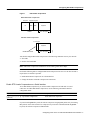
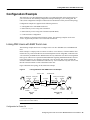
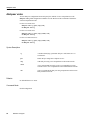
Configuring RTP Header Compression
Real-Time Transport Protocol (RTP) is used for carrying packetized audio traffic over an IP network.
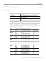
RTP header compression compresses the IP/UDP/RTP header in an RTP data packet from 40 bytes
to approximately 2 to 4 bytes (most of the time), as shown in Figure 1.
This compression feature is beneficial if you are running Voice over IP over slow links. Enabling
compression on both ends of a low-bandwidth serial link can greatly reduce the network overhead if
there is a lot of RTP traffic on that slow link.
Typically, an RTP packet has a payload of approximately 20 to 160 bytes for audio applications that
use compressed payloads. RTP header compression is especially beneficial when the RTP payload
size is small (for example, compressed audio payloads between 20 and 50 bytes).
6
Release 12.0(7)XK
Configuring RTP Header Compression
Figure 1
RTP Header Compression
Before RTP header compression:
20 bytes
IP
8 bytes 12 bytes
UDP
RTP
Header
Payload
20 to 160 bytes
After RTP header compression:
2 to 4 bytes
IP/UDP/RTP header
20 to 160 bytes
12076
Payload
You should configure RTP header compression if the following conditions exist in your network:
•
•
Slow links
Need to save bandwidth
Note RTP header compression should not be used on links greater than 2 Mbps.
Perform the following tasks to configure RTP header compression for Voice over IP. The first task is
required; the second task is optional.
•
•
Enable RTP Header Compression on a Serial Interface
Change the Number of Header Compression Connections
Enable RTP Header Compression on a Serial Interface
To use RTP header compression, you need to enable compression on both ends of a serial
connection. To enable RTP header compression, use the following command in interface
configuration mode:
Command
Purpose
router(config-if)# ip rtp header-compression
[passive]
Enable RTP header compression.
If you include the passive keyword, the software compresses outgoing RTP packets only if incoming
RTP packets on the same interface are compressed. If you use the command without the passive
keyword, the software compresses all RTP traffic.
Configuring Voice over IP for Cisco MC3810 Series Concentrators 7
Configuring IP Networks for Real-Time Voice Traffic
Change the Number of Header Compression Connections
By default, the software supports a total of 32 RTP header compression connections on an interface.
To specify a different number of RTP header compression connections, use the following command
in interface configuration mode:
Command
Purpose
router(config-if)# ip rtp compression connections
number
Specify the total number of RTP header compression
connections supported on an interface.
RTP Header Compression Configuration Example
The following example enables RTP header compression for a serial interface:
interface 0
ip rtp header-compression
encapsulation ppp
ip rtp compression-connections 25
For more information about RTP header compression, see the “Configuring IP Multicast Routing”
chapter of the Network Protocols Configuration Guide, Part 1.
Configuring IP RTP Priority
IP RTP Priority provides a strict priority queueing scheme for delay-sensitive data such as voice.
Voice traffic can be identified by its Real-Time Transport Protocol (RTP) port numbers and classified
into a priority queue configured by the ip rtp priority command. The result is that voice is serviced
as strict priority in preference to other nonvoice traffic.
This feature allows you to specify a range of User Datagram Protocol (UDP)/RTP ports whose voice
traffic is guaranteed strict priority service over any other queues or classes using the same output
interface. Strict priority means that if packets exist in the priority queue, they are dequeued and sent
first—that is, before packets in other queues are dequeued.
The IP RTP Priority feature does not require that you know the port of a voice call. Rather, the feature
gives you the ability to identify a range of ports whose traffic is put into the priority queue. Moreover,
you can specify the entire voice port range—16384 to 32767—to ensure that all voice traffic is given
strict priority service. IP RTP Priority is especially useful on slow-speed links whose speed is less
than 1.544 Mbps.
This feature can be used in conjunction with Weighted Fair Queueing (WFQ) on the same outgoing
interface.Traffic matching the range of ports specified for the priority queue is guaranteed strict
priority over other WFQ flows; voice packets in the priority queue are always serviced first.
When used in conjunction with WFQ, the ip rtp priority command provides strict priority to voice,
and WFQ scheduling is applied to the remaining queues.
Because voice packets are small in size and the interface also can have large packets going out, the
Link Fragmentation and Interleaving (LFI) feature should also be configured on lower speed
interfaces. When you enable LFI, the large data packets are broken up so that the small voice packets
can be interleaved between the data fragments that make up a large data packet. LFI prevents a voice
packet from needing to wait until a large packet is sent. Instead, the voice packet can be sent in a
shorter amount of time.
For more information about the IP RTP Priority feature, see the IP RTP Priority Cisco IOS Release
12.0(5)T online document.
8
Release 12.0(7)XK
Configuring Number Expansion
To reserve a strict priority queue for a set of RTP packet flows belonging to a range of UDP
destination ports, use the following command in interface configuration mode:
Command
Purpose
router(config-if)# ip rtp priority
starting-rtp-port-number port-number-range bandwidth
Reserves a strict priority queue for a set of RTP packet
flows belonging to a range of UDP destination ports.
Configuring Number Expansion
This section describes how to use the num-exp command to expand a set of dialed digits, such as an
extension number, into a destination pattern representing a complete telephone number for Voice
over IP on Cisco MC3810 concentrators.
Enter the following command in global configuration mode for each extension number to be
expanded into a destination pattern.
Command
Purpose
router(config)# num-exp extension-number
extension-string
(Optional) If using the number expansion feature, define a
destination pattern for an extension number. Repeat for
each extension to be expanded.
Configuring Dial Peers
This section describes how to use new commands defining dial-peer operation for Voice over IP on
Cisco MC3810 series concentrators.
Configure POTS Dial Peers
POTS dial peers enable incoming calls to be received by a particular telephony device. To configure
a POTS peer, you need to uniquely identify the peer (by assigning it a unique tag number), define its
telephone number(s), and associate it with a voice port through which calls will be established.
Under most circumstances, the default values for the remaining dial-peer configuration commands
will be sufficient to establish connections.
To enter dial-peer configuration mode (and select POTS as the method of voice-related
encapsulation), use the following command in global configuration mode:
Command
Purpose
router(config)# dial-peer voice number pots
Enter the dial-peer configuration mode to configure a
POTS peer.
The number value of the dial-peer voice pots command is a tag that uniquely identifies the dial peer.
(This number has local significance only.) The tag value identifies the dial peer and must be unique
on the router. Do not duplicate a specific tag number.
To configure the identified POTS peer, use the following commands in dial-peer configuration mode:
Step
Command
Purpose
1
router(config-dialpeer)# destination-pattern
string
Define the telephone number associated with this POTS dial
peer.
Note
Configuring Voice over IP for Cisco MC3810 Series Concentrators 9
Configuring Dial Peers
Step
Command
Purpose
2
router(config-dialpeer)# port slot/port
Associate this POTS dial peer with a specific voice port.
To configure direct inward dial (DID) for a particular POTS dial peer, use the following commands
beginning in global configuration mode:
Step
Command
Purpose
1
router(config)# dial-peer voice number pots
Enter dial-peer configuration mode to configure a POTS peer.
2
router(config-dialpeer)#direct-inward-dial
Specify direct inward dial for this POTS peer.
Note Direct inward dial is configured for the calling POTS dial peer.
Note Direct inward dial is only configured on the POTS dial peer if it corresponds to a BRI or
PRI/QSIG interface. It should not be configured to correspond to an analog or T1/E1 CAS interface.
For additional POTS dial-peer configuration options, refer to the “Voice-Related Commands”
section of the Cisco IOS 12.0 Voice, Video, and Home Applications Command Reference.
Configure VoIP Peers
VoIP peers enable outgoing calls to be made from a particular telephony device. To configure a VoIP
peer, you need to uniquely identify the peer (by assigning it a unique tag number), define its
destination telephone number and destination IP address. As with POTS peers, under most
circumstances, the default values for the remaining dial-peer configuration commands will be
adequate to establish connections.
To enter the dial-peer configuration mode (and select VoIP as the method of voice-related
encapsulation), use the following command in global configuration mode:
Command
Purpose
router(config)#dial-peer voice number voip
Enter the dial-peer configuration mode to configure a
VoIP peer.
The number value of the dial-peer voice voip command is a tag that uniquely identifies the dial peer.
To configure the identified VoIP peer, use the following commands in dial-peer configuration mode:
Step
Command
Purpose
1
router(config-dialpeer)#destination-pattern
string
Define the destination telephone number associated with this
VoIP dial peer.
2
router(config-dialpeer)#session target
{ipv4:destination-address | dns:host-name | ras}
Specify a destination IP address for this dial peer.
10
Release 12.0(7)XK
Configuring Dial Peer Hunting
Step
Command
Purpose
3
router(config-dialpeer)# dtmf-relay [cisco-rtp]
[h245-signal] [h245-alphanumeric]
(Optional) Specify how an H.323 gateway relays DTMF
tones through an IP network. Options allow the gateway to
forward tones “out-of-band”, or separate from the voice
stream.
Note This command is only supported if your Cisco MC3810
has version 549 or newer DSPs.
For additional VoIP dial-peer configuration options, refer to the “Voice-Related Commands” section
of the Cisco IOS 12.0 Voice, Video, and Home Applications Command Reference. For examples of
how to configure dial peers, refer to the section, “Voice over IP Configuration Examples.”
Validation Tips
You can check the validity of your dial-peer configuration by performing the following tasks:
•
If you have relatively few dial peers configured, you can use the show dial-peer voice command
to verify that the data configured is correct. Use this command to display a specific dial peer or
to display all configured dial peers.
•
Use the show dialplan number command to show the dial peer to which a particular number
(destination pattern) resolves.
Troubleshooting Tips
If you are having trouble connecting a call and you suspect the problem is associated with dial-peer
configuration, you can try to resolve the problem by performing the following tasks:
•
Ping the associated IP address to confirm connectivity. If you cannot successfully ping your
destination, refer to the Cisco IOS 12.0 Network Protocols Configuration Guide, Part 1.
•
•
Use the show dial-peer voice command to verify that the operational status of the dial peer is up.
•
If you have configured number expansion, use the show num-exp command to check that the
partial number on the local router maps to the correct full E.164 telephone number on the remote
router.
•
If you have configured a codec value, there can be a problem if both VoIP dial peers on either
side of the connection have incompatible codec values. Make sure that both VoIP peers have been
configured with the same codec value.
•
•
•
Use the debug vpm spi command to verify the output string the router dials is correct.
Use the show dialplan number command on the local and remote routers to verify that the data
is configured correctly on both.
Use the debug cch323 rtp command to check RTP packet transport.
Use the debug cch323 h225 command to check the call setup.
Configuring Dial Peer Hunting
After you have configured dial peers, you can configure how the router or concentrator performs
dial-peer hunting functions. To configure dial-peer hunting behavior, perform the following steps
beginning in global configuration mode.
Configuring Voice over IP for Cisco MC3810 Series Concentrators 11
Configuring Dial Peers
Step
Command
Purpose
1
router(config)# dial-peer hunt
(Optional) Specify the hunting selection order for dial peers.
2
router(config)# dial-peer terminator character
(Optional) Designate a terminating character for variable length
dialed numbers. The default character is # (pound sign).
If using dial peer hunting, there may be situations in which you want to disable dial-peer hunting on
a specific dial peer. To disable dial-peer hunting on a dial peer, use the following commands
beginning in global configuration mode:
Step
Command
Purpose
1
router(config)# dial-peer voice tag {pots | voip}
Enter dial-peer configuration mode for the specified dial peer.
2
router(config-dial-peer)# huntstop
Disable dial-peer hunting on the dial peer. Once you enter this
command, no further hunting will be allowed if a call fails on the
specified dial peer.
To reenable dial-peer hunting on a dial peer, enter the no huntstop command.
Configuring Dial Peer Digit Manipulation
After you have configured dial peers, you can configure the dial-peer digit manipulation. To
configure dial-peer digit manipulation, perform one or more of the following steps beginning in
dial-peer configuration mode.
Step
Command
Purpose
1
router(config-dialpeer)# forward-digits
{num-digit | all | extra}
(Optional) If using the forward-digits feature, configure the
digit-forwarding method. The range for the number of digits
forwarded (num-digit) is 0 to 32.
or
router(config-dialpeer)# default forward-digits
or
router(config-dialpeer)# no forward-digits
Refer to the command reference section for an explanation of
the command options.
In the default condition, dialed digits not matching the
destination pattern are forwarded.
Note The no state is not the default state.
2
router(config-dialpeer)# prefix string
(Optional) If the forward-digits feature was not configured in
the last step, assign the dialed digits prefix for the dial peer.
3
router(config-dialpeer)# preference value
(Optional) Configure a preference for the POTS dial peer. The
value is a number from 0 (highest preference) to 10 (lowest
preference). If POTS and voice-network (VoFR, VoATM, VoIP)
dial peers are mixed in the same hunt group, POTS dial peers
will be searched first, even if a voice-network peer has a higher
preference number.
12
Release 12.0(7)XK
Optimizing Dial Peer and Network Interface Configurations
Optimizing Dial Peer and Network Interface Configurations
Depending on how you have configured your network interfaces, you might need to configure
additional VoIP dial-peer parameters. This section describes the following topics:
•
•
•
Configuring IP Precedence for Dial Peers
Configuring Codec and VAD for Dial Peers
Configuring Codec Selection Order
Configuring IP Precedence for Dial Peers
If you want to give real-time voice traffic a higher priority than other network traffic, you can weight
the voice data traffic associated with a particular VoIP dial peer by using IP Precedence. IP
Precedence provides no admission control.
To give real-time voice traffic precedence over other IP network traffic, use the following commands,
beginning in global configuration mode:
Step
Command
Purpose
1
router(config)# dial-peer voice number voip
Enter the dial-peer configuration mode to configure a VoIP peer.
2
router(config-dialpeer)# ip precedence number
Select a precedence level for the voice traffic associated with that
dial peer.
In IP Precedence, the numbers 1 through 5 identify classes for IP flows; the numbers 6 through 7 are
used for network and backbone routing and updates.
For example, to ensure that voice traffic associated with VoIP dial peer 103 is given a higher priority
than other IP network traffic, enter the following:
dial-peer voice 103 voip
ip precedence 5
In this example, when an IP call leg is associated with VoIP dial peer 103, all packets transmitted to
the IP network via this dial peer will have their precedence bits set to 5. If the networks receiving
these packets have been configured to recognize precedence bits, the packets will be given priority
over packets with a lower configured precedence value.
Configuring Codec and VAD for Dial Peers
Coder-decoder (codec) and voice activity detection (VAD) for a dial peer determine how much
bandwidth the voice session uses. Codec typically is used to transform analog signals into a digital
bit stream and digital signals back into analog signals—in this case, it specifies the voice coder rate
of speech for a dial peer. VAD is used to disable the transmission of silence packets.
Configuring Codec for a VoIP Dial Peer
To specify a voice coder rate for a selected VoIP peer, use the following commands beginning in
global configuration mode:
Step
Command
Purpose
1
router(config)# dial-peer voice number voip
Enter the dial-peer configuration mode to configure a VoIP peer.
Configuring Voice over IP for Cisco MC3810 Series Concentrators 13
Optimizing Dial Peer and Network Interface Configurations
Step
Command
Purpose
2
router(config-dialpeer)# codec {g711alaw |
g711ulaw | g723ar53 | g723ar63 | g723r53 |
g723r63 | g726r16 | g726r24 | g726r32 | g728 |
g729abr8 | g729ar8 | g729br8 | g729r8}[bytes
payload-size]
Specify the desired voice coder rate of speech.Optionally specify
the voice payload (in bytes) of each frame.
The default for the codec command is g729r8; normally the default configuration for this command
is the most desirable. If, however, you are operating on a high bandwidth network and voice quality
is of the highest importance, you should configure the codec command for g711alaw or ulaw. Using
this value will result in better voice quality, but it will also require higher bandwidth requirements
for voice.
For example, to specify a codec rate of G.711a-law for VoIP dial peer 108, enter the following:
dial-peer voice 108 voip
destination-pattern +14085551234
codec g711alaw
session target ipv4:10.0.0.8
Configuring VAD for a VoIP Dial Peer
To disable the transmission of silence packets for a selected VoIP peer, use the following commands
beginning in global configuration mode:
Step
Command
Purpose
1
router(config)# dial-peer voice number voip
Enter dial-peer configuration mode to configure a VoIP peer.
2
router(config)# vad
Disable the transmission of silence packets (enabling VAD).
The default for the vad command is enabled; normally the default configuration for this command
is the most desirable. If you are operating on a high bandwidth network and voice quality is of the
highest importance, you should disable vad. Using this value will result in better voice quality, but
it will also require higher bandwidth requirements for voice.
For example, to enable VAD for VoIP dial peer 108, enter the following:
dial-peer voice 108 voip
destination-pattern +14085551234
vad
session target ipv4:10.0.0.8
Configuring Codec Selection Order
To configure codec selection order, perform the following tasks:
•
•
Configuring a Voice Class to Define Codec Selection Order
Applying a Voice Class for Codec Selection to a VoIP Dial Peer
Configuring a Voice Class to Define Codec Selection Order
You can define a voice class in which you configure a selection order for codecs, and then map the
voice class to a VoIP dial peer.
14
Release 12.0(7)XK
Configuring Codec Selection Order
To configure a voice class in which you can define the order of preference in which a router selects
a codec when it negotiates with a far-end router, enter the following commands beginning in global
configuration mode:
Step
Command
Purpose
Create a voice class for a codec preference list. The range for the tag number
is 1 to 10000. The tag number must be unique on the router.
1
router(config)# voice class codec tag
2
router(config-voice-class)# codec
preference priority codec [bytes
payload-size]
Configure the selection order of preference for a codec. Repeat this command
to specify selection orders of preference for additional codecs, if required.
3
router(config-voice-class) #exit
Exit from voice-class configuration mode.
Applying a Voice Class for Codec Selection to a VoIP Dial Peer
After you have created the voice class, assign it to a VoIP dial peer. You cannot assign voice-class
codec attributes to POTS dial peers.
To apply voice-class signaling attributes to a VoIP dial peer, complete the following steps beginning
in global configuration mode:
Step
1
Command
router(config)# dial-peer voice
tag voip
Purpose
Define a VoIP dial peer and enter dial-peer configuration mode. All subsequent
commands that you enter in dial-peer voice mode before you exit will apply to this
dial peer.
The tag is a number that identifies the dial peer and must be unique on the router. Do
not assign duplicate tag numbers.
2
router(config-dialpeer)#
voice-class codec tag
Assign to the dial peer the voice class that you created in the “Configuring a Voice
Class to Define Codec Selection Order” section.
Note The voice-class command in dial-peer configuration mode is entered with a
hyphen. The voice class command in global configuration mode is entered without the
hyphen.
Configuring Voice over IP for Cisco MC3810 Series Concentrators 15
Configuring Voice Ports
Verifying Codec Settings of Dial Peers
To display the codec voice-classes assigned to VoIP dial peers, enter the show running-config
command.
The following example shows exerpts from the show running-config command output, where three
codec voice classes (10, 20 and 30) have been applied to three VoIP dial peers (101, 102 and 102):
router# show running-config
Building configuration...
Current configuration:
!
version 12.0
.
.
.
voice class codec 10
codec preference 1 g711alaw
codec preference 2 g711ulaw bytes 80
codec preference 3 g726r16 bytes 120
!
voice class codec 20
codec preference 1 g726r24 bytes 90
codec preference 2 g726r32 bytes 120
!
voice class codec 30
codec preference 1 g729ar8
codec preference 2 g726r16
codec preference 3 g726r32
!
.
.
.
dial-peer voice 101 voip
voice-class codec 10
!
dial-peer voice 102 voip
voice-class codec 20
!
dial-peer voice 103 voip
voice-class codec 30
!
line con 0
transport input none
line aux 0
line 2 3
line vty 0 4
password #1writer
login
!
end
Configuring Voice Ports
This section describes how to configure voice ports for Voice over IP (VoIP) on Cisco MC3810
series concentrators.
Perform the following tasks, as applicable, to configure voice ports:
•
•
16
Configuring FXO or FXS Voice Ports
Fine-Tuning FXO and FXS Voice Ports
Release 12.0(7)XK
Configuring FXO or FXS Voice Ports
•
•
•
Configuring E&M Voice Ports
Fine-Tuning E&M Voice Ports
Activating the Voice Port
Configuring FXO or FXS Voice Ports
Under most circumstances the default values are adequate for FXO and FXS voice ports.
Task List
If you need to change the default configuration for these voice ports, perform the following tasks:
1 Configure the applicable parameters for the voice port.
2 Verify the configuration.
3 Troubleshoot and correct any configuration errors.
Configuration Procedure
To configure FXO and FXS voice ports, enter the following commands, beginning in global
configuration mode. Commands apply to both analog and digital voice ports unless otherwise
indicated.
Step
Command
Purpose
1
router(config)# voice-port slot/port
Identify the voice port you want to configure and enter voice-port
configuration mode.
2
router(config-voice-port)#connection {plar |
tie-line | trunk | plar-opx} string
Specify the voice-port connection type and the destination
telephone number.
• plar for private line auto ringdown
• tie-line for a tie-line connection to a PBX
• plar-opx for PLAR off-premises extension (the local voice
port provides a local response before the remote voice port
receives an answer)
• string specifies the destination telephone number.
3
router(config-voice-port)#voice
confirmation-tone
If connection plar or connection plar-opx is configured, enable
the two-beep confirmation tone that a caller hears when picking
up the handset.
4
router(config-voice-port)#dial-type {dtmf |
pulse}
If you are configuring for rotary dialing, select pulse as the
out-dialing type. The default is touch-tone (dtmf).
5
router(config-voice-port)#signal {loop-start |
ground-start}
(Analog only) Select the appropriate signaling type.
6
router(config-voice-port)#cptone country
Select the appropriate call progress tone for your country
location.
Out-dialing type is not applicable on FXS voice ports.
The default is northamerica. For a list of supported countries,
refer to the Voice, Video, and Home Applications Command
Reference.
Configuring Voice over IP for Cisco MC3810 Series Concentrators 17
Configuring Voice Ports
Step
Command
Purpose
7
router(config-voice-port)#compand-type {u-law |
a-law}
Configure the companding standard used to convert between
analog and digital signals in PCM systems. Defaults are: u-law
for T1; a-law for E1.
8
router(config-voice-port)#vad
(Optional) Enable voice activity detection (VAD).
9
router(config-voice-port)#comfort-noise
(Optional) Enable background noise if VAD is enabled.
10
router(config-voice-port)#music-threshold number
(Optional) Specify the maximum volume (in dBm) for on-hold
music. Valid entries are –70 to –30.
11
router(config-voice-port)#description string
(Optional) Describe the location, connected equipment, or other
information about the voice port. The description is displayed
when a show command is entered.
12
router(config-voice-port)#exit
Exit from voice-port configuration mode.
13
router(config)# voice-card 0
Enter voice-card configuration mode and specify voice card 0.
Voice card 0 provides the configuration mode for setting the
codec complexity on a Cisco MC3810.
14
router(config-voicecard)# codec complexity
| medium}
{high
Specify the codec complexity for this Cisco MC3810 according
to the bandwidth requirements and the number of voice channels
to be supported per DSP. The default is medium complexity,
which provides four voice channels per DSP.
Note You cannot change codec complexity while DS0 groups
are defined. If they are already set up, use the no ds0-group
command before resetting the codec complexity.
15
router(config-voice-ca)#exit
Exit from voice-card configuration mode.
16
router(config-voice-port)#exit
Exit from voice-port configuration mode.
Validation Tips
You can check the validity of your voice-port configuration by performing the following tasks:
•
•
Pick up the handset of an attached telephony device and check for dial tone.
•
Use the show voice port or show voice port summary command to view the voice-port
configuration.
•
•
Use the show voice dsp command to view the current status of all DSP voice channels.
If you have dial tone, check for DTMF detection. If the dial tone stops when you dial a digit, the
voice port is most likely configured properly.
Use the show voice call summary command to view the call status for all voice ports.
Troubleshooting Tips
If you are having trouble connecting a call and you suspect the problem is associated with voice-port
configuration, you can try to resolve the problem by performing the following tasks:
18
•
Ping the associated IP address to confirm connectivity. If you cannot successfully ping your
destination, refer to the Network Protocols Configuration Guide, Part 1.
•
Use the show voice port command to make sure that the port is enabled. If the port is offline,
enter the no shutdown command.
•
Check to see if the analog personality module is correctly installed. For more information, refer
to the hardware installation guide for your router or concentrator.
Release 12.0(7)XK
Fine-Tuning FXO and FXS Voice Ports
Fine-Tuning FXO and FXS Voice Ports
Depending on the specifics of your particular network, you may need to adjust voice parameters
involving timing, input gain, and output attenuation. The commands for these parameters are
referred to as voice-port tuning commands.
Note In most cases, the default values for voice-port tuning commands will be sufficient.
Task List
To fine tune FXO and FXS voice ports, perform the following tasks:
1 Perform the voice-port tuning procedure for the voice port.
2 Verify the configuration.
3 Troubleshoot and correct any configuration errors.
Voice-Port Tuning Procedure
To fine-tune FXO and FXS voice ports, perform the following optional steps, beginning in global
configuration mode. Commands apply to both analog and digital voice ports unless otherwise
indicated.
Note After you change voice-port parameters, Cisco recommends that you cycle the port by
entering the shutdown and no shutdown commands.
Step
Command
Purpose
1
router(config)#voice-port slot/port
Identify the voice port you want to configure and enter voice-port
configuration mode.
2
router(config-voiceport)#input gain value
Specify the receive gain (in dB) for the voice port. Value range is
–6 to 14.
3
router(config-voiceport)#output attenuation
value
Specify the transmit attenuation (in dB) for the voice port. Value
range is 0 to 14.
4
router(config-voiceport)#echo-cancel enable
Enable echo-cancellation of voice that is sent out the interface
and received back on the same interface.
5
router(config-voiceport)#echo-cancel coverage
{16 | 24 | 32}
Set the duration (in milliseconds) of echo cancellation. Values
are 16, 24, and 32.
6
router(config-voiceport)#non-linear
Enable non-linear processing, which shuts off any signal if no
near-end speech is detected. (Non-linear processing is used with
echo-cancellation.)
7
router(config-voiceport)#playout-delay
Tune the playout buffer to accommodate packet jitter caused by
switches in the WAN.
Configuring Voice over IP for Cisco MC3810 Series Concentrators 19
Configuring Voice Ports
Step
Command
Purpose
8
router(config-voiceport)# condition {tx-a-bit |
tx-b-bit | tx-c-bit | tx-d-bit} {rx-a-bit |
rx-b-bit | rx-c-bit | rx-d-bit} {on | off |
invert}
(For T1/E1 digital voice ports only.) Configure the voice port to
manipulate the transmit and/or receive bit patterns to match the
bit patterns required by a connected device.
Be careful not to destroy the information content of the bit
pattern. For example, forcing the A-bit on or off will prevent
FXO interfaces from being able to generate both an on-hook and
off-hook state.
Note The show voice port command reports at the protocol
level, while the show controller command reports at the driver
level. The driver is not notified of any bit manipulation using the
condition command. As a result, the show controller command
output will not account for the bit conditioning.
9
router(config-voiceport)# timeouts initial
seconds
Specify the number of seconds the system waits for a caller to
dial the first digit. The range is 10 to 120. The default is 10.
10
router(config-voiceport)# timeouts interdigit
seconds
Specify the number of seconds the system waits, after a caller has
dialed the initial digit, for the caller to dial each subsequent digit.
The range is 0 to 120. The default is 10.
11
router(config-voiceport)# timeouts ringing
{seconds | infinity}
Specify the maximum number of seconds that a voice port allows
ringing to continue if a call is not answered.
The range is 5 to 60000. The default is 180.
12
router(config-voiceport)# timeouts wait-release
{seconds | infinity}
Specify the maximum number of seconds that a voice port can
remain in the call failure state while the router or concentrator
sends a busy tone, reorder tone, or out-of-service tone to the port.
The value range is 5 to 3600. The default is 30.
13
router(config-voiceport)# timing digit
milliseconds
If the dial type is DTMF, configure the DTMF digit signal
duration in milliseconds. The range is 50 to 100. The default is
100.
14
router(config-voiceport)# timing inter-digit
milliseconds
If the dial type is DTMF, configure the DTMF inter-digit signal
duration in milliseconds. The range is 50 to 500. The default is
100.
15
router(config-voiceport)# timing pulse-digit
milliseconds
If the dial type is pulse, configure the pulse digit signal duration
in milliseconds. The range is 10 to 20. The default is 20.
16
router(config-voiceport)# timing
pulse-inter-digit milliseconds
If the dial type is pulse, configure the pulse inter-digit signal
duration in milliseconds. The range is 100 to 1000. The default is
500.
17
router(config-voiceport)# timing percentbreak
percent
(FXO only) Specify the percentage of the break period for
dialing pulses. The range is 20 to 80. The default is 50.
18
router(config-voiceport)# timing guard-out
milliseconds
(FXO only) Specify the duration in milliseconds of the guard-out
period to prevent this port from seizing a remote FXS port before
the remote port detects a disconnect signal. The range is 300 to
3000. The default is 2000.
19
router(config-voiceport)# impedance {600r | 600c
| 900r | 900c}
(FXO only) Configure the impedance. The default is 600r (600
ohms real).
20
router(config-voiceport)# ring number number
(Analog FXO only) Configure the number of rings detected
before a call is answered on the FXO port. The range is 1 to 10.
The default is 1.
21
router(config-voiceport)# ring frequency number
(FXS only) Specify the local ring frequency (Hertz) for the FXS
voice port. Valid entries are 20 and 30. The default is 20.
20
Release 12.0(7)XK
Configuring E&M Voice Ports
Step
Command
Purpose
22
router(config-voiceport)# disconnect-ack
(FXS only) Configure the voice port to return an
acknowledgment upon receipt of a disconnect signal.
23
router(config-voiceport)# ring cadence
{[pattern01 | pattern02 | pattern03 | pattern04 |
pattern05 | pattern06 | pattern07 | pattern08 |
pattern09 | pattern10 | pattern11 | pattern12 ]
[define pulse-interval]}
(FXS only) Specify the on and off times for the ringing pulses.
See the command reference section for details on the ring
cadence options.
24
router(config-voiceport)#exit
Exit from voice-port configuration mode.
Configuring E&M Voice Ports
The default E&M voice-port parameters will probably not be sufficient to enable voice transmission
over your network. Configuration parameters depend on the PBX to which the voice port is
connected.
Note E&M voice-port values must match those of the PBX to which the voice port is connected.
Refer to the documentation that came with your PBX to determine the E&M voice-port
configuration values.
Task List
To configure E&M voice ports, perform the following tasks:
1 Configure the applicable parameters for the voice port.
2 Verify the configuration.
3 Troubleshoot and correct any configuration errors.
Configuration Procedure
To configure E&M voice ports, enter the following commands beginning in global configuration
mode. Commands apply to both analog and digital voice ports unless otherwise indicated.
Step
Command
Purpose
1
router(config)# voice-port slot/port
Identify the voice port you want to configure and enter voice-port
configuration mode.
Configuring Voice over IP for Cisco MC3810 Series Concentrators 21
Configuring Voice Ports
Step
Command
Purpose
2
router(config-voiceport)# connection {plar |
tie-line | trunk | plar-opx} destination-string
[answer-mode]
Specify the voice-port connection type and the destination
telephone number.
• plar specifies a private line automatic ring down (PLAR)
connection. PLAR is an autodialing mechanism that
permanently associates a voice interface with a far-end voice
interface, allowing call completion to a specific telephone
number or PBX without dialing. When the calling telephone
goes off hook a predefined network dial peer is automatically
matched, which sets up a call to the destination telephone or
PBX.
• tie-line specifies a connection that emulates a temporary
tie-line trunk to a private branch exchange (PBX). A tie-line
connection is automatically set up for each call and torn down
when the call ends.
• trunk specifies a connection that emulates a permanent trunk
connection to a private branch exchange (PBX). A trunk
connection remains “nailed up” in the absence of any active
calls.
• plar-opx specifies a PLAR Off-Premises eXtension
connection. Using this option, the local voice-port provides a
local response before the remote voice-port receives an
answer. On FXO interfaces, the voice-port will not answer
until the remote side answers.
• destination-string specifies the destination telephone number.
When configuring Cisco-trunk permanent calls, one side must be
the call initiator (master) and the other side is normally the call
answerer (slave). By default, the voice port operates in master
mode. Enter the answer-mode keyword to specify that the voice
port should operate in slave mode.
3
router(config-voiceport)# voice
confirmation-tone
If connection plar-opx is configured, enable the two-beep
confirmation tone that a caller hears when picking up the
handset.
4
router(config-voiceport)# dial-type {dtmf | pulse
| mf }
Select the dial type for dialing out.
• dtmf for touch-tone (the default)
• pulse for rotary dial
• mf for multifrequency tone dialing
5
22
router(config-voiceport)# operation {2-wire |
4-wire}
Release 12.0(7)XK
Select the appropriate cabling scheme for this voice port.
Configuring E&M Voice Ports
Step
Command
Purpose
6
router(config-voiceport)# type {1 | 2 | 3 | 5}
Select the appropriate E&M interface type.
Type 1 lead configuration:
E—output, relay to ground
M—input, referenced to ground
Type 2 lead configuration:
E—output, relay to SG
M—input, referenced to ground
SB—feed for M, connected to –48V
SG—return for E, galvanically isolated from ground
Type 3 lead configuration:
E—output, relay to ground
M—input, referenced to ground
SB—connected to –48V
SG—connected to ground
Type 5 lead configuration:
E—output, relay to ground
M—input, referenced to –48V.
7
router(config-voiceport)# signal {wink-start |
immediate | delay-dial}
Configure the E&M signaling type. The default is wink-start.
8
router(config-voiceport)# cptone country
Select the appropriate call progress tone for your country
location.
The default is northamerica. For a list of supported countries,
refer to the Voice, Video, and Home Applications Command
Reference.
9
router(config-voiceport)# compand-type {u-law |
a-law}
Configure the companding standard used to convert between
analog and digital signals in PCM systems. Defaults are: u-law
for T1; a-law for E1.
10
router(config-voiceport)# no vad
(Optional) Disable voice activity detection (VAD). VAD is
enabled by default.
11
router(config-voiceport)# comfort-noise
(Optional) Enable background noise if VAD is enabled.
12
router(config-voiceport)# music-threshold number
(Optional) Specify the maximum volume (in dBm) for on-hold
music. Valid entries are –70 to –30. The default is –38.
13
router(config-voiceport)# voice
confirmation-tone
(Optional) If the voice port is configured for connection
plar-opx for Off-Premises eXtension, disable the two-beep
confirmation tone that a caller hears when picking up the
handset.
14
router(config-voiceport)# description string
(Optional) Describe the location, connected equipment, or other
information about the voice port. The description is displayed
when a show command is entered.
15
router(config-voice-port)#exit
Exit from voice-port configuration mode.
Configuring Voice over IP for Cisco MC3810 Series Concentrators 23
Configuring Voice Ports
Validation Tips
You can check the validity of your voice-port configuration by performing the following tasks:
•
•
Pick up the handset of an attached telephony device and check for dial tone.
•
•
•
Use the show voice port command to view the voice-port configuration.
If you have dial tone, check for DTMF detection. If the dial tone stops when you dial a digit, the
voice port is most likely configured properly.
Use the show voice dsp command to view the current status of all DSP voice channels.
Use the show voice call summary command to view the call status for all voice ports.
Troubleshooting Tips
If you are having trouble connecting a call and you suspect the problem is associated with voice-port
configuration, you can try to resolve the problem by performing the following tasks:
•
Ping the associated IP address to confirm connectivity. If you cannot successfully ping your
destination, refer to the Cisco IOS 12.0 Network Protocols Configuration Guide, Part 1.
•
Use the show voice port command to make sure that the port is enabled. If the port is offline,
enter the no shutdown command.
•
•
Make sure that the values pertaining to your PBX setup, such as timing and type, are correct.
Check to see if the analog personality module is correctly installed. For more information, refer
to the Cisco MC3810 Multiservice Concentrator Hardware Installation Guide.
Fine-Tuning E&M Voice Ports
Depending on the specifics of your particular network, you may need to adjust voice parameters
involving timing, input gain, and output attenuation. The commands for these parameters are
referred to as voice-port tuning commands.
Note In most cases, the default values for voice-port tuning commands will be sufficient.
Task List
To fine tune E&M voice ports, perform the following tasks:
1 Perform the voice-port tuning procedure for the voice port.
2 Verify the configuration.
3 Troubleshoot and correct any configuration errors.
Voice-Port Tuning Procedure
To fine-tune E&M voice ports, perform the following steps, beginning in privileged EXEC mode.
Commands apply to both analog and digital voice ports unless otherwise indicated.
Note After you change voice-port parameters, Cisco recommends that you cycle the port by
entering the shutdown and no shutdown commands.
24
Release 12.0(7)XK
Fine-Tuning E&M Voice Ports
Step
Command
Purpose
1
router# configure terminal
Enter global configuration mode.
2
router(config)# voice-port slot/port
Identify the voice port you want to configure and enter voice-port
configuration mode.
3
router(config-voiceport)# input gain value
Specify the receive gain (in dB) for the voice port. Value range is
–6 to 14.
4
router(config-voiceport)# output attenuation
value
Specify the transmit attenuation (in dB) for the voice port. Value
range is 0 to 14.
5
router(config-voiceport)# echo-cancel enable
Enable echo-cancellation of voice that is sent out the interface
and received back on the same interface.
6
router(config-voiceport)# echo-cancel coverage
milliseconds
Set the duration (in milliseconds) of echo cancellation. Values
are 16, 24, and 32.
7
router(config-voiceport)# non-linear
Enable non-linear processing, which shuts off any signal if no
near-end speech is detected. (Non-linear processing is used with
echo-cancellation.)
8
router(config-voiceport)# playout-delay
Tune the playout buffer to accommodate packet jitter caused by
switches in the WAN.
9
router(config-voiceport)# condition {tx-a-bit |
tx-b-bit | tx-c-bit | tx-d-bit} {rx-a-bit |
rx-b-bit | rx-c-bit | rx-d-bit} {on | off |
invert}
(For T1/E1 digital voice ports only.) Configure the voice port to
manipulate the transmit and/or receive bit patterns to match the
bit patterns required by a connected device.
Be careful not to destroy the information content of the bit
pattern. For example, forcing the A-bit on or off will prevent
FXO interfaces from being able to generate both an on-hook and
off-hook state.
Note The show voice port command reports at the protocol
level, while the show controller command reports at the driver
level. The driver is not notified of any bit manipulation using the
condition command. As a result, the show controller command
output will not account for the bit conditioning.
10
router(config-voiceport)# define {Tx-bits |
Rx-bits} {seize | idle} {0000 | 0001 | 0010 |
0011 | 0100 | 0101 | 0110 | 0111 | 1000 | 1001 |
1010 | 1011 | 1100 | | 1101 | 1110 | 1111}
(For T1/E1 digital voice ports only.) Define specific transmit
and/or receive signaling bits to match the bit patterns required by
a connected device.
11
router(config-voiceport)# ignore {rx-a-bit |
rx-b-bit | rx-c-bit | rx-d-bit}
(For T1/E1 digital voice ports only.) Configure the voice port to
ignore specified transmit and/or receive bits.
12
router(config-voiceport)# timeouts initial
seconds
Specify the number of seconds the system waits for a caller to
dial the first digit. The range is 0 to 120. The default is 10.
13
router(config-voiceport)# timeouts interdigit
seconds
Specify the number of seconds the system waits (after a caller
has dialed the initial digit) for the caller to dial each subsequent
digit. The range is 0 to 120. The default is 10.
14
router(config-voiceport)#timeouts ringing
{seconds | infinity}
Specify the maximum number of seconds that a voice port allows
ringing to continue if a call is not answered.
The range is 5 to 60000. The default is 180.
15
router(config-voiceport)# timeouts wait-release
{seconds | infinity}
Specify the maximum number of seconds that a voice port can
remain in the call failure state while the router or concentrator
sends a busy tone, reorder tone or out-of-service tone to the port.
The value range is 5 to 3600. The default is 30.
Configuring Voice over IP for Cisco MC3810 Series Concentrators 25
Configuring Voice Ports
Step
Command
Purpose
16
router(config-voiceport)# timing clear-wait
milliseconds
Specify the number of milliseconds between the inactive seizure
signal and the call being cleared. The range is 100 to 2000. The
default is 400.
17
router(config-voiceport)# timing delay-duration
milliseconds
Specify the delay signal duration in milliseconds for delay dial
signaling. This command applies only if the signal command is
set to delay-dial. The range is 100 to 5000. The default is 140.
18
router(config-voiceport)# timing delay-start
milliseconds
Specify the number of milliseconds of delay from the outgoing
seizure to the outdial address. This value applies only if the
signal command is set to delay-dial. The range is 100 to 290.
The default is 150.
19
router(config-voiceport)# timing dialout-delay
milliseconds
Configure the delay interval before sending a dialed digit or
cut-through. This value applies only if the signal command is set
to immediate. The range is 100 to 5000. The default is 300.
20
router(config-voiceport)# timing
delay-with-integrity milliseconds
Specify the number of milliseconds duration of the wink pulse
for delay dials. The range is 0 to 5000. The default is 0.
21
router(config-voiceport)# timing dial-pulse
min-delay milliseconds
If the dial type is pulse, specify the number of milliseconds
between generation of wink-like pulses. The range is 140 to
5000. The default is 140.
22
router(config-voiceport)# timing wink-duration
milliseconds
Specify the length in milliseconds of the wink-start signal. This
command applies only if the signal command is set to
wink-start. The range is from 100 to 400 milliseconds and the
default is 200.
23
router(config-voiceport)# timing wink-wait
milliseconds
Specify the wink-wait duration in milliseconds for a wink-start
signal. This command applies only if the signal command is set
to wink-start. The range is 100 to 5000. The default is 200.
24
router(config-voiceport)# timing percentbreak
percent
Specify the percentage of the break period for dialing pulses. The
range is 20 to 80. The default is 50.
25
router(config-voiceport)# timing digit
milliseconds
If the dial type is DTMF, configure the DTMF digit signal
duration in milliseconds. The range is 50 to 100. The default is
100.
26
router(config-voiceport)# timing inter-digit
milliseconds
If the dial type is DTMF, configure the DTMF inter-digit signal
duration in milliseconds. The range is 50 to 500. The default is
100.
27
router(config-voiceport)# timing pulse
pulses-per-second
If the dial type is pulse, specify the pulse dialing rate in pulses
per second. The range is 10 to 20. The default is 10.
28
router(config-voiceport)# timing pulse-digit
milliseconds
If the dial type is pulse, specify the pulse digit duration in
milliseconds. The range is 10 to 20. The default is 20.
29
router(config-voiceport)# timing
pulse-inter-digit milliseconds
If the dial type is pulse, configure the pulse inter-digit duration in
milliseconds. The range is 100 to 1000. The default is 500.
30
router(config-voice-port)#exit
Exit from voice-port configuration mode.
26
Release 12.0(7)XK
Activating the Voice Port
Activating the Voice Port
After you have configured the voice port, you need to activate the voice port to bring it online. Cisco
recommends that you cycle the port—shut the port down and then bring it online again.
To activate a voice port, enter the following command in voice-port configuration mode:
Command
Purpose
router(config-voiceport)# no shutdown
Activate the voice port.
To cycle a voice port, enter the following commands in voice-port configuration mode:
Step
Command
Purpose
1
router(config-voiceport)# shutdown
Deactivate the voice port.
2
router(config-voiceport)# voice-port slot/port
Identify the voice port you want to activate and enter the
voice-port configuration mode.
3
router(config-voiceport)# no shutdown
Activate the voice port.
4
router(config-voice-port)#exit
Exit from voice-port configuration mode.
Note If you are not going to use a voice port, shut it down.
Configuring the H.323 Gateway
In this release, basic gateway Registration, Admission, and Status (RAS) protocol capability is
extended to the Cisco MC3810. Other features, such as authentication, authorization, and accounting
(AAA) enhancements for security and accounting services, interactive voice response (IVR),
Integrated Services Digital Network (ISDN) redirect number support, and rotary call pattern
support, will be offered in future Cisco IOS releases.
To configure the H.323 Gateway, you need to perform the following tasks
•
•
•
Configuring POTS and VoIP Dial Peers
Enabling VoIP Gateway Functionality
Configuring Gateway Interface Parameters
Configuring POTS and VoIP Dial Peers
The first step in configuring the H.323 gateway is to define the applicable POTS and VoIP dial peers.
The POTS dial peer informs the system which voice port to direct incoming VoIP calls. The VoIP
dial peer defines how to direct calls that originate from a local voice port into the VoIP cloud to the
session target. The session target command indicates the address of the remote gateway where the
call is terminated. There are several different ways to define the destination gateway address: by
statically configuring the IP address of the gateway, by defining the DNS of the gateway, or by using
RAS. If you use RAS, that gateway determines the destination target by querying the RAS
gatekeeper. See the “Configuring Dial Peers” section on page 9 to define dial peers for VoIP.
Configuring Voice over IP for Cisco MC3810 Series Concentrators 27
Configuring the H.323 Gateway
Enabling VoIP Gateway Functionality
Enable VoIP gateway functionality by using the gateway command.
To enable gateway functionality, use the following commands:
Step
Command
Purpose
1
router# configure terminal
Enter global configuration mode.
2
router(config)# gateway
Enable the VoIP gateway.
Configuring Gateway Interface Parameters
The next step in configuring an H.323 gateway is to configure the gateway interface parameters. First
define which interface will be presented to the VoIP network as this gateway’s H.323 interface. Only
one interface is allowed to be the gateway interface. You can select either the interface that is
connected to the gatekeeper or a loopback interface. The interface that is connected to the gatekeeper
is usually a LAN interface (for example, Fast Ethernet, Ethernet, FDDI, or Token Ring).
After you define the gateway interface, configure the gateway to discover the gatekeeper either
through multicasting or by directing it to a specific host. Then configure the gateway’s H.323
identification number and any technology prefixes that this gateway should register with the
gatekeeper.
To define the interface to be used as the H.323 gateway interface and configure the H.323 gateway
interface parameters, use the following commands, beginning in global configuration mode:
Step
Command
Purpose
1
router(config)# interface type slot/port
Enter interface configuration mode to configure parameters for
the specified interface.
2
router(config-if)# ip address ip-address
subnet-mask
Specify the IP address for this interface.
3
router(config-if)#h323-gateway voip interface
Designate this interface as the H.323 gateway interface.
4
router(config-if)#h323-gateway voip h323-id
interface-id
Specify an H.323 name (ID) for the gateway associated with this
interface. This ID is used by this gateway when this gateway
communicates with the gatekeeper. Usually, this H.323 ID is the
name given to the gateway with the gatekeeper domain name
appended to the end.
5
router(config-if)#h323-gateway voip id gatekeeper
{ipaddr ip-address [port]| multicast}
Specify the name (ID) of the gatekeeper associated with this
gateway and how the gateway finds it. The gatekeeper ID
configured here must exactly match the gatekeeper ID in the
gatekeeper configuration. The gateway determines the location of
the gateway in one of two ways: either by a defined IP address or
through multicast.
6
router(config-if)#h323-gateway voip tech-prefix
prefix
Specify a technology prefix. A technology prefix is used to
identify a type of service that this gateway is capable of
providing.
Note If a gateway is capable of handling multiple services,
specify each service with a tech-prefix command.
7
router(config-if)#exit
Exit interface configuration mode.
8
router(config)#exit
Exit global configuration mode.
28
Release 12.0(7)XK
Linking PBX Users with E&M Trunk Lines
Configuration Example
The actual Voice over IP configuration procedure you complete depends on the actual topology of
your voice network. The following configuration examples should give you a starting point. Of
course, these configuration examples would need to be customized to reflect your network topology.
Configuration examples are supplied for the following scenarios:
•
•
•
•
Linking PBX Users with E&M Trunk Lines
PSTN Gateway Access Using FXO Connection
PSTN Gateway Access Using FXO Connection (PLAR Mode)
Codec Preference Configuration
These examples are described in the following sections. The following examples use the term
“router” to generically describe Cisco routers and concentrators.
Linking PBX Users with E&M Trunk Lines
The following example shows how to configure Voice over IP to link PBX users with E&M trunk
lines.
In this example, a company wants to connect two offices: one in San Jose, California and the other
in Salt Lake City, Utah. Each office has an internal telephone network using PBX, connected to the
voice network by an E&M interface. Both the Salt Lake City and the San Jose offices are using E&M
Port Type II, with four-wire operation and ImmediateStart signaling. Each E&M interface connects
to the router using two voice interface connections. Users in San Jose dial “8-569” and then the
extension number to reach a destination in Salt Lake City. Users in Salt Lake City dial “4-527” and
then the extension number to reach a destination in San Jose.
Figure 2 illustrates the topology of this connection example.
Linking PBX Users with E&M Trunk Lines Example
172.16.1.123
Dial peer
1 POTS
Voice port
1/0/0
PBX
Dial peer
2 POTS
Router SJ
Voice port
1/0/1
San Jose
(408)
172.16.65.182
IP cloud
Voice port Dial peer
1 POTS
1/0/0
PBX
Router SLC
Voice port
1/0/1
Dial peer
2 POTS
Salt Lake City
(801)
S6616
Figure 2
Note This example assumes that the company already has established a working IP connection
between its two remote offices.
Configuration for Router SJ
hostname sanjose
Configuring Voice over IP for Cisco MC3810 Series Concentrators 29
Configuring the H.323 Gateway
!Configure pots dial peer 1
dial-peer voice 1 pots
destination-pattern 555....
port 1/0/0
!Configure pots dial peer 2
dial-peer voice 2 pots
destination-pattern 555....
port 1/0/1
!Configure voip dial peer 3
dial-peer voice 3 voip
destination-pattern 119....
session target ipv4:172.16.65.182
!Configure the E&M interface
voice-port 1/0/0
signal immediate
operation 4-wire
type 2
voice-port 1/0/1
signal immediate
operation 4-wire
type 2
!Configure the serial interface
interface serial 0/0
description serial interface type dce (provides clock)
clock rate 2000000
ip address 172.16.1.123
no shutdown
Configuration for Router SLC
hostname saltlake
!Configure pots dial peer 1
dial-peer voice 1 pots
destination-pattern 119....
port 1/0/0
!Configure pots dial peer 2
dial-peer voice 2 pots
destination-pattern 119....
port 1/0/1
!Configure voip dial peer 3
dial-peer voice 3 voip
destination-pattern 555....
session target ipv4:172.16.1.123
!Configure the E&M interface
voice-port 1/0/0
signal immediate
operation 4-wire
type 2
voice-port 1/0/0
signal immediate
operation 4-wire
type 2
!Configure the serial interface
30
Release 12.0(7)XK
PSTN Gateway Access Using FXO Connection
interface serial 0/0
description serial interface type dte
ip address 172.16.65.182
no shutdown
Note PBXs should be configured to pass all DTMF signals to the Cisco voice router. Cisco
recommends that you do not configure store and forward tone.
Note If you change the gain or the telephony port, make sure that the telephony port still accepts
DTMF signals.
PSTN Gateway Access Using FXO Connection
The following example shows how to configure Voice over IP to link users with the PSTN gateway
using an FXO connection.
In this example, users connected to Router SJ in San Jose, California can reach PSTN users in Salt
Lake City, Utah via Router SLC. Router SLC in Salt Lake City is connected directly to the PSTN
through an FXO interface.
Figure 3 illustrates the topology of this connection example.
Figure 3
PSTN Gateway Access Using FXO Connection Example
PSTN user
IP cloud
Router SJ
Router SLC
PSTN
cloud
1(408) 555-4000
172.16.65.182
Voice port
Salt Lake City
1/0/0
S6617
172.16.1.123
Voice port
San Jose
1/0/0
Note This example assumes that the company already has established a working IP connection
between its two remote offices.
Configuration for Router SJ
! Configure pots dial peer 1
dial-peer voice 1 pots
destination-pattern +14085554000
port 1/0/0
! Configure voip dial peer 2
dial-peer voice 2 voip
destination-pattern 9...........
session target ipv4:172.16.65.182
Configuring Voice over IP for Cisco MC3810 Series Concentrators 31
Configuring the H.323 Gateway
! Configure the serial interface
interface serial 0/0
clock rate 2000000
ip address 172.16.1.123
no shutdown
Configuration for Router SLC
! Configure pots dial peer 1
dial-peer voice 1 pots
destination-pattern 9...........
port 1/0/0
! Configure voip dial peer 2
dial-peer voice 2 voip
destination-pattern +14085554000
session target ipv4:172.16.1.123
! Configure serial interface
interface serial 0/0
ip address 172.16.65.182
no shutdown
PSTN Gateway Access Using FXO Connection (PLAR Mode)
The following example shows how to configure Voice over IP to link users with the PSTN gateway
using an FXO connection (PLAR mode).
In this example, PSTN users in Salt Lake City, Utah, can dial a local number and establish a private
line connection in a remote location. As in the previous example, Router SLC in Salt Lake City is
connected directly to the PSTN through an FXO interface.
Figure 4 illustrates the topology of this connection example.
Figure 4
PSTN Gateway Access Using FXO Connection (PLAR Mode)
PLAR connection
PSTN user
IP cloud
Router SJ
Router SLC
PSTN
cloud
1(408) 555-4000
Voice port
1/0/0
172.16.65.182
Voice port
1/0/0
Salt Lake City
S6618
172.16.1.123
San Jose
Note This example assumes that the company already has established a working IP connection
between its two remote offices.
32
Release 12.0(7)XK
Codec Preference Configuration
Configuration for Router SJ
! Configure pots dial peer 1
dial-peer voice 1 pots
destination-pattern +14085554000
port 1/0/0
! Configure voip dial peer 2
dial-peer voice 2 voip
destination-pattern 9...........
session target ipv4:172.16.65.182
! Configure the serial interface
interface serial 0/0
clock rate 2000000
ip address 172.16.1.123
no shutdown
Configuration for Router SLC
! Configure pots dial peer 1
dial-peer voice 1 pots
destination-pattern 9...........
port 1/0/0
! Configure voip dial peer 2
dial-peer voice 2 voip
destination-pattern +14085554000
session target ipv4:172.16.1.123
! Configure the voice-port
voice-port 1/0/0
connection plar 14085554000
! Configure the serial interface
interface serial 0/0
ip address 172.16.65.182
no shutdown
Codec Preference Configuration
The following example enters voice class codec configuration mode, creates voice class 10, and
defines a preference list of 12 codecs:
router(config)# voice
router(config-class)#
router(config-class)#
router(config-class)#
router(config-class)#
router(config-class)#
router(config-class)#
router(config-class)#
router(config-class)#
router(config-class)#
router(config-class)#
router(config-class)#
router(config-class)#
router(config-class)#
router(config-class)#
router(config)#
class
codec
codec
codec
codec
codec
codec
codec
codec
codec
codec
codec
codec
exit
exit
codec 10
preference
preference
preference
preference
preference
preference
preference
preference
preference
preference
preference
preference
1 g711alaw
2 g711ulaw bytes 80
3 g723ar53
4 g723ar63 bytes 144
5 g723r53
6 g723r63 bytes 120
7 g726r16
8 g726r24
9 g726r32 bytes 80
10 g728
11 g729br8
12 g729r8 bytes 50
Configuring Voice over IP for Cisco MC3810 Series Concentrators 33
Configuring the H.323 Gateway
The following example assigns a voice class 10 to a VoIP dial peer:
router(config)# dial-peer voice 25 voip
router(config-dial-peer)# voice-class codec 10
34
Release 12.0(7)XK
Codec Preference Configuration
Command Reference
This section documents new or modified commands. Modified commands are indicated by an
asterisk (*). All other commands used on these platforms are documented in the Cisco IOS Release
12.0 command reference publications.
•
•
•
•
•
•
•
•
•
•
•
•
•
•
•
•
•
•
•
codec preference*
connection*
dial-peer hunt*
dial-peer terminator*
dial-peer voice*
ds0-group*
dtmf-relay
forward-digits*
huntstop*
icpif
incoming called-number
num-exp*
session target*
show call active voice*
show call history voice*
show num-exp*
voice class codec*
voice-class codec (dial-peer)*
voice-group*
Configuring Voice over IP for Cisco MC3810 Series Concentrators 35
codec preference
codec preference
To define the order of preference in which network dial peers select codecs, use the codec
preference voice-class configuration command. Enter the no form of this command to restore the
default order of preference.
codec preference priority codec bytes payload-size
no codec preference
Syntax Description
priority
The order of selection preference you assign to a codec. The valid range is 1 to 12,
where 1 is the highest priority.
codec
Codec options.
Note
Codecs with asterisk (*) are not supported on Cisco MC3810 series equipped
with a voice compression module (VCM); a high-performance compression
module (HCM) is required to support these codecs.
g711alaw—G.711 A Law 64000 bps
g711ulaw—G.711 u Law 64000 bps
g723ar53—*G.723.1 Annex A 5300 bps
g723ar63—*G.723.1 Annex A 6300 bps
g723r53— *G.723.1 5300 bps
g723r63—*G.723.1 6300 bps
g726r16—G.726 16000 bps
g726r24— G.726 24000 bps
g726r32—G.726 32000 bps
g728—*G.728 16000 bps
g729abr8—*G.729 Annex A and Annex B 8000 bps
g729ar8—G.729 Annex A 8000 bps
g729br8—*G.729 Annex B 8000 bps
g729r8—G.729 8000 bps
bytes
(Optional) The voice payload for each frame.
payload-size (Optional) Number of bytes you specify as the voice payload of each frame. Values
depend on the codec type and the packet voice protocol. See Table 1 for valid entries
and default values.
Defaults
If no codec is specified, dial peers are configured for g729r8 and the voice payload is as shown in
Table 1 for G.729r8.
If a codec is specified without the bytes keyword, the voice payload is as shown in Table 1.
36
Release 12.0(7)XK
codec preference
Command Modes
Voice class configuration
Command History
Release
Modification
12.0(2)XH
This command was introduced on the Cisco AS5300.
12.0(7)T
This command was first supported on the Cisco 2600 and
3600 series routers.
12.0(7)XK
This command was first supported on the Cisco MC3810
series.
Usage Guidelines
The routers at opposite ends of the WAN may have to negotiate the codec selection for the network
dial peers. The codec preference command specifies the order of preference for selecting a
negotiated codec for the connection. Table 1 describes the voice payload options and default values
for the codecs and packet voice protocols.
Table 1
Voice Payload-per-Frame Options and Defaults
Codec
Protocol
Voice Payload Options (bytes)
Default Voice
Payload (bytes)
g711alaw
g711ulaw
VoIP
VoFR
VoATM
80, 160
40 to 240 in multiples of 40
40 to 240 in multiples of 40
160
240
240
g723ar53
g723r53
VoIP
VoFR
VoATM
20 to 220 in multiples of 20
20 to 240 in multiples of 20
20 to 240 in multiples of 20
20
20
20
g723ar63
g723r63
VoIP
VoFR
VoATM
24 to 216 in multiples of 24
24 to 240 in multiples of 24
24 to 240 in multiples of 24
24
24
24
g726r16
VoIP
VoFR
VoATM
20 to 220 in multiples of 20
10 to 240 in multiples of 10
10 to 240 in multiples of 10
40
60
60
g726r24
VoIP
VoFR
VoATM
30 to 210 in multiples of 30
15 to 240 in multiples of 15
30 to 240 in multiples of 15
60
90
90
g726r32
VoIP
VoFR
VoATM
40 to 200 in multiples of 40
20 to 240 in multiples of 20
40 to 240 in multiples of 20
80
120
120
g728
VoIP
VoFR
VoATM
10 to 230 in multiples of 10
10 to 240 in multiples of 10
10 to 240 in multiples of 10
40
60
60
Configuring Voice over IP for Cisco MC3810 Series Concentrators 37
codec preference
Table 1
Voice Payload-per-Frame Options and Defaults
Codec
Protocol
Voice Payload Options (bytes)
Default Voice
Payload (bytes)
g729abr8
g729ar8
g729br8
g729r8
VoIP
VoFR
VoATM
10 to 230 in multiples of 10
10 to 240 in multiples of 10
10 to 240 in multiples of 10
20
30
30
Examples
The following example shows how to create a voice class and specify a codec selection preference
for the voice class starting from global configuration mode:
router(config)# voice
router(config-class)#
router(config-class)#
router(config-class)#
router(config-class)#
router(config-class)#
router(config-class)#
router(config-class)#
router(config-class)#
router(config-class)#
router(config-class)#
router(config-class)#
router(config-class)#
router(config-class)#
router(config)# exit
router)#
class
codec
codec
codec
codec
codec
codec
codec
codec
codec
codec
codec
codec
exit
codec 10
preference
preference
preference
preference
preference
preference
preference
preference
preference
preference
preference
preference
1 g711alaw
2 g711ulaw bytes 80
3 g723ar53
4 g723ar63 bytes 144
5 g723r53
6 g723r63 bytes 120
7 g726r16
8 g726r24
9 g726r32 bytes 80
10 g728
11 g729br8
12 g729r8 bytes 50
Related Commands
38
Command
Description
voice class codec
Enters voice-class configuration mode and assigns an
identification tag number for a codec voice class.
voice-class codec (dial-peer)
Assigns a previously-configured codec selection preference list to
a dial peer.
Release 12.0(7)XK
connection
connection
To specify a connection mode for a voice port, use the connection voice-port configuration
command. Use the no form of this command to disable the selected connection mode.
connection {plar | tie-line | plar-opx} digits | {trunk digits [answer-mode]}
no connection {plar | tie-line | plar-opx} digits | {trunk digits [answer-mode]}
Syntax Description
plar
Specifies a private line auto ring down (PLAR) connection. PLAR is handled by
associating a peer directly with an interface; when an interface goes off-hook, the peer
is used to set up the second call leg and conference them together without the caller
having to dial any digits.
tie-line
Specifies a tie-line connection to a private branch exchange (PBX).
plar-opx
Specifies a PLAR Off-Premises eXtension connection. Using this option, the local
voice-port provides a local response before the remote voice-port receives an answer.
On FXO interfaces, the voice-port will not answer until the remote side answers.
digits
The destination telephone number. Valid entries are any series of digits that specify the
E.164 telephone number.
trunk
Specifies a straight tie-line connection to a private branch exchange (PBX).
answer-mode
(Optional; used only with the trunk keyword.) Specifies that the router should not
attempt to initiate a trunk connection, but should wait for an incoming call before
establishing the trunk.
Defaults
No connection mode is specified.
Command Mode
Voice-port configuration
Command History
Release
Modification
11.3(1)T
This command was first introduced.
11.3(1)MA1
This command was first supported on the Cisco MC3810, and the
tie-line keyword was first made available on the Cisco MC3810.
11.3(1)MA5 and 12.0(2)T
The plar-opx keyword was first made available on the Cisco MC3810
as the plar-opx-ringrelay keyword. The keyword was shortened in a
subsequent release.
12.0(3)XG and 12.0(4)T
The trunk keyword was made available on the Cisco MC3810.
The trunk answer-mode option was added.
12.0(7)XK
This command options were unified across the Cisco 2600, 3600, and
MC3810 platforms.
Configuring Voice over IP for Cisco MC3810 Series Concentrators 39
connection
Usage Guidelines
Use this command to specify a connection mode for a specific interface. For example, use the
connection plar command to specify a PLAR interface. The string you configure for this command
is used as the called number for all incoming calls over this connection. The destination peer is
determined by the called number.
Use the connection trunk command to specify a straight tie-line connection to a PBX. You can use
the connection trunk command for E&M-to-E&M trunks, FXO-to-FXS trunks, and FXS-to-FXS
trunks. Signaling will be transported for E&M-to-E&M trunks and FXO-to-FXS trunks; signaling
will not be transported for FXS-to-FXS trunks.
If you desire one of the devices in a static trunk connection to act as slave and receive calls only, use
the answer-mode option with the connection trunk command when configuring that device.
Note When using the connection trunk command, you must perform a shutdown/no shutdown
command sequence on the voice port.
The connection tie-line command is used on the Cisco router when a dial plan requires that
additional digits be added in front of any digits dialed by the PBX, and that the combined set of digits
be used to route the call via the dial-peers and into the network. The operation is similar to the
connection plar command operation, but in this case the tie-line port also waits to collect digits from
the PBX. The tie-line digits are also automatically stripped by a terminating port.
If the connection command is not configured, the standard session application outputs a dial tone
when the interface goes off-hook until enough digits are collected to match a dial-peer and complete
the call.
Examples
The following example selects PLAR as the connection mode on a Cisco 3600, with a destination
telephone number of 555-9262:
router(config)# voice-port 1/0/0
router(config-voiceport)# connection plar 5559262
The following example selects tie-line as the connection mode on a Cisco MC3810, with a
destination telephone number of 555-9262:
router(config)# voice-port 1/1
router(config-voiceport)# connection tie-line 5559262
The following example specifies a PLAR off-premises extension connection on a Cisco 3600, with
a destination telephone number of 555-9262:
router(config)# voice-port 1/0/0
router(config-voiceport)# connection plar-opx 5559262
The following example configures a Cisco 3600 series router for a trunk connection and specifies
that it will establish the trunk only when it receives an incoming call:
router(config)# voice-port 1/0/0
router(config-voiceport)# connection trunk 5559262 answer-mode
40
Release 12.0(7)XK
connection
Related Commands
Command
Description
destination-pattern
Specifies either the prefix or the full E.164 telephone number to be
used for a dial peer.
dial-peer voice
Enters dial-peer configuration mode and specifies the method of
voice-related encapsulation.
session-protocol
Establishes a session protocol for calls between the local and remote
routers via the packet network.
session-target
Configures a network-specific address for a dial peer.
Configuring Voice over IP for Cisco MC3810 Series Concentrators 41
dial-peer hunt
dial-peer hunt
To specify a hunt selection order for dial-peers, use the dial-peer hunt dial-peer configuration
command. Use the no form of this command to restore the default selection order.
dial-peer hunt hunt-order-number
no dial-peer hunt
Syntax Description
hunt-order-number
A number from 0 to 7 that selects a predefined hunting selection order:
0—Longest match in phone number, explicit preference, random
selection. This is the default hunt order number.
1—Longest match in phone number, explicit preference, least recent use.
2—Explicit preference, longest match in phone number, random
selection.
3—Explicit preference, longest match in phone number, least recent use.
4—Least recent use, longest match in phone number, explicit preference.
5—Least recent use, explicit preference, longest match in phone number.
6—Random selection.
7—Least recent use.
Defaults
The default is longest match in phone number, explicit preference, random selection (hunt order
number 0).
Command Mode
Global configuration
Command History
Release
Modification
12.0(7)XK
This command was first introduced and was first supported on the
Cisco 2600 and 3600 Series routers and on the Cisco MC3810
multiservice access concentrator.
Usage Guidelines
Use the dial-peer hunt dial-peer configuration command if you have configured hunt groups.
“Longest match in phone number” refers to the destination pattern that matches the greatest number
of the dialed digits. “Explicit preference” refers to the preference setting in the dial-peer
42
Release 12.0(7)XK
dial-peer hunt
configuration. “Least recent use” refers to the destination pattern that has waited the longest since
being selected. “Random selection” weights all of the destination patterns equally in a random
selection mode.
Example
The following example configures the dial peers to hunt in the following order: (1) longest match in
phone number, (2) explicit preference, (3) random selection.
configure terminal
dial-peer hunt 0
Related Commands
Command
Description
destination-pattern
Specifies the prefix or the complete telephone number for a dial peer.
preference
Specifies the preferred selection order of a dial peer within a hunt
group.
show dial-peer voice
Displays configuration information for dial peers.
Configuring Voice over IP for Cisco MC3810 Series Concentrators 43
dial-peer terminator
dial-peer terminator
To change the character used as a terminator for variable length dialed numbers, use the dial-peer
terminator global configuration command. Use the no form of this command to restore the default
terminating character.
dial-peer terminator character
no dial-peer terminator
Syntax Description
character
Designates the terminating character for a variable-length dialed
number. Valid numbers and characters are #, *, 0, 1, 2, 3, 4, 5, 6, 7,
8, 9, a, b, c, and d. The default is #.
Defaults
The default terminating character is #.
Command Mode
Global configuration
Command History
Release
Modification
12.0
This command was introduced.
12.0(7)XK
Usage was restricted to variable-length dialed numbers.
Usage Guidelines
There are certain areas in the world (for example, in certain European countries) where telephone
numbers can vary in length. When a dialed-number string has been identified as a variable length
dialed-number, the system does not place a call until the configured value for the timeouts
interdigits command has expired, or until the caller dials the terminating character. Use the
dial-peer terminator global configuration command to change the terminating character.
Example
The following example specifies “9” as the terminating character for variable-length dialed numbers:
configure terminal
dial-peer terminator 9#
44
Release 12.0(7)XK
dial-peer terminator
Related Commands
Command
Description
answer-address
Specifies the preferred selection order of a dial peer within a hunt
group.
destination-pattern
Specifies the prefix or the complete telephone number for a dial peer.
timeouts interdigit
Specifies the interdigit timeout value for a voice port, in seconds.
show dial-peer voice
Displays configuration information for dial peers.
Configuring Voice over IP for Cisco MC3810 Series Concentrators 45
dial-peer voice
dial-peer voice
To enter dial-peer configuration mode and specify the method of voice encapsulation, use the
dial-peer voice global configuration command. Use the no form of this command to disable the
selected encapsulation mode.
For the Cisco 2600 series:
dial-peer voice tag {pots | voip | vofr}
no dial-peer voice tag
For the Cisco 3600 series:
dial-peer voice tag {pots | voip | voatm | vofr }
no dial-peer voice tag
For the Cisco MC3810 series:
dial-peer voice tag {pots | voip | voatm | vofr }
no dial-peer voice tag
Syntax Description
tag
A number identifying a particular dial peer. Valid entries are 1 to
2147483647.
pots
POTS dial peer using basic telephone service.
voip
VoIP dial peer using voice encapsulation on the POTS network.
voatm
(Cisco 3600 and MC3810 only) Voice over ATM dial peer using
real-time AAL5 voice encapsulation on the ATM backbone network.
vofr
Voice over Frame Relay dial peer using encapsulation on the Frame
Relay backbone network.
Defaults
No default behavior or values.
Command Mode
Global configuration
46
Release 12.0(7)XK
dial-peer voice
Command History
Release
Modification
11.3(1)T
This command was first introduced.
11.3(1)MA
This command was first supported on the Cisco MC3810, with
support for POTS, VoFR, and VoATM.
12.0(3)XG and 12.0(4)T
This command added VoFR to the Cisco 2600 and 3600 series routers.
12.0(4)T
This command added VoFR to the Cisco 7200 series platform.
12.0(7)XK
This command added VoIP to the Cisco MC3810 and VoATM to the
Cisco 3600 series routers.
Usage Guidelines
Use the dial-peer voice global configuration command to switch to the dial-peer configuration mode
from the global configuration mode. Use the exit command to exit the dial-peer configuration mode
and return to the global configuration mode.
Example
The following example accesses dial-peer configuration mode and configures a POTS peer identified
as dial peer 10:
configure terminal
dial-peer voice 10 pots
Related Commands
Command
Description
voice-port
Enters voice-port configuration mode.
Configuring Voice over IP for Cisco MC3810 Series Concentrators 47
ds0-group
ds0-group
To specify the DS0 timeslots that make up a logical voice port on a T1 or E1 controller, and to specify
the signaling type, use the ds0-group controller configuration command. Use the no form of the
command to remove the DS0 group and signaling setting.
ds0-group ds0-group-no timeslots timeslot-list type signal-type
no ds0-group ds0-group-no
Syntax Description
ds0-group-no
A value from 0 to 23 that identifies the DS0 group.
timeslot-list
timeslot-list is a single timeslot number, a single range of numbers, or
multiple ranges of numbers separated by commas. For T1, allowable values
are from 1 to 24. Examples are:
• 2
• 1-15, 17-24
• 1-23
• 2, 4, 6-12
type
The signaling method selection for type depends on the connection that you
are making. The E&M interface allows connection for PBX trunk lines (tielines) and telephone equipment. The FXS interface allows connection of
basic telephone equipment and PBXs. The FXO interface is for connecting
the central office (CO) to a standard PBX interface where permitted by local
regulations. The FXO interface is often used for off-premises extensions.
The options are as follows:
• e&m-immediate-start—no specific off-hook and on-hook signaling
• e&m-delay-dial—the originating endpoint sends an off-hook signal and
then waits for an off-hook signal followed by an on-hook signal from the
destination
• e&m-wink-start—the originating endpoint sends an off-hook signal and
waits for a wink signal from the destination
• fxs-ground-start—Foreign Exchange Station ground-start signaling
support
• fxs-loop-start —Foreign Exchange Station loop-start signaling support
• fxo-ground-start—Foreign Exchange Office ground-start signaling
support
• fxo-loop-start—Foreign Exchange Office loop-start signaling support
48
Release 12.0(7)XK
ds0-group
The following options are available only on E1 controllers on the
Cisco MC3810:
• e&m-melcas-immed—E&M Mercury Exchange Limited Channel
Associated Signaling (MELCAS) immediate start signaling support
• e&m-melcas-wink—E&M MELCAS wink start signaling support
• e&m-melcas-delay—E&M MELCAS delay start signaling support
• fxo-melcas—MELCAS Foreign Exchange Office signaling support
• fxs-melcas—MELCAS Foreign Exchange Station signaling support
The following options are available only when the mode ccs command is
enabled on the Cisco MC3810 for transparent CCS support:
• ext-sig-master—For the specified channel(s), automatically generates the
off-hook signal and stays in the off-hook state.
• ext-sig-slave—For the specified channel(s), automatically generates the
answer signal when a call is terminated to that channel.
Default
No DS0 group is defined.
Command Mode
Controller configuration
Command History
Release
Modification
11.2
This command was introduced for the Cisco AS5300 as cas-group.
12.0(1)T
The cas-group command was first supported on the Cisco 3600
series.
12.0(5)T
This command was renamed ds0-group on the Cisco AS5300 and on
the Cisco 2600 and 3600 series (requires Digital T1 Packet Voice
Trunk Network Modules).
12.0(7)XK
Support for this command was extended to the Cisco MC3810. When
the ds0-group command became available on the Cisco MC3810, the
voice-group command was removed and is no longer supported.
Usage Guidelines
The ds0-group command automatically creates a logical voice port that is numbered as follows:
Cisco 2600 and 3600 series:
slot/port:ds0-group-no.
Cisco MC3810:
slot:ds0-group-no
Configuring Voice over IP for Cisco MC3810 Series Concentrators 49
ds0-group
On the Cisco MC3810, the slot number is the controller number. Although only one voice port is
created for each group, applicable calls are routed to any channel in the group.
On the Cisco MC3810 when configured for transparent CCS, the channel type configured as the
ext-sig-master is considered the master side of the permanent virtual circuit (PVC) connection
which is responsible for establishing the PVC connection. After the master channel is configured, a
fixed timer of 30 seconds starts. The voice-signaling driver then generates an off-hook signal on the
master voice channel after the timer expires. The call is treated as a regular call, and the master
channel does not hang up after the connection is made. If the call does not go through, or if the T1/E1
trunk is down, the 30-second timer on the master channel side restarts. A new off-hook signal is then
generated at the master channel side after the timer expires.
Examples
The following example configures ranges of T1 controller timeslots for FXS ground-start and FXO
loop-start signaling on a Cisco 2600 or 3600 Series router:
router(config)# controller
router(config-controller)#
router(config-controller)#
router(config-controller)#
router(config-controller)#
T1 1/0
framing esf
linecode b8zs
ds0-group 1 timeslot 1-10 type fxs-ground-start
ds0-group 2 timeslot 11-24 type fxo-loop-start
The following example configures DS0 groups 1 and 2 on controller T1 1 on the Cisco MC3810 to
support transparent CCS:
router(config)# controller
router(config-controller)#
router(config-controller)#
router(config-controller)#
T1 1
mode ccs cross-connect
ds0-group 1 timeslot 1-10 type ext-sig-master
ds0-group 2 timeslot 11-24 type ext-sig-slave
Related Command
50
Command
Description
codec complexity
Matches the DSP complexity packaging to the codec(s) to be
supported
mode ccs
Configures the T1/E1 controller to support CCS cross-connect or CCS
frame-forwarding.
Release 12.0(7)XK
dtmf-relay
dtmf-relay
Use the dtmf-relay command to specify how an H.323 gateway relays DTMF tones through an IP
network. Options allow the gateway to forward tones “out-of-band”, or separate from the voice
stream. The no form of this command removes all signaling options and transmits the DTMF tones
as part of the audio stream.
dtmf-relay [cisco-rtp] [h245-signal] [h245-alphanumeric]
no dtmf-relay
Syntax Description
cisco-rtp
(Optional) Forwards DTMF tones using RTP protocol with a Cisco proprietary
payload type.
h245-signal
(Optional) Forwards DTMF tones using the H.245 “signal” User Input Indication
method. Supports tones 0-9, *, #, and A-D.
h245-alphanumeric
(Optional) Forwards DTMF tones using the H.245 “alphanumeric” User Input
Indication method. Supports tones 0-9, *, #, and A-D.
Default
DTMF tones are sent “inband”, or left in the audio stream, unless you use this command.
Command Mode
EXEC
Command History
Release
Modification
11.3(2) NA
This command was introduced.
12.0(5)T
This command was modified for H.323 V2, adding dtmf-relay and
h245-signal.
12.0(7)XK
This command is supported on the Cisco MC3810
Usage Guidelines
The dtmf-relay command determines the outgoing format of relayed DTMF tones. The gateway
automatically accepts all formats.
The gateway only sends DTMF tones in the format you specify if the remote device supports it. If
the remote device supports multiple formats, the gateway chooses the format based on the following
priority:
1 cisco-rtp (highest priority)
2 h245-signal
3 h245-alphanumeric
4 None – DTMF sent inband
Configuring Voice over IP for Cisco MC3810 Series Concentrators 51
dtmf-relay
Note The cisco-rtp version of dtmf-relay is a proprietary Cisco implementation and only
interoperates between Cisco AS5300 universal access servers, Cisco 2600 or 3600 modular access
routers, or Cisco MC3810 concentrators running Cisco IOS Release 12.0(7)XK, or later releases.
Otherwise, the DTMF relay feature will not function and the gateway will send DTMF tones inband.
Note The h245-alphanumeric and h245-signal DTMF settings on an MC310 concentrator require
a high-performance compression module (HCM) and are not supported on an MC3810 concentrator
with a non-HCM voice compression module (VCM).
Example
The following are two examples of the dtmf-relay command:
•
Configuring with dtmf-relay cisco-rtp or h245-signal when sending to dial-peer 103. Enter the
configuration commands, one per line.
Router# configure terminal
Router(config)# dial-peer voice 103 voip
Router(config-dial-peer)# dtmf-relay cisco-rtp h245-signal
Router(config-dial-peer)# end
Router#
•
Configuring the gateway to send DTMF inband (the default) when sending to dial-peer 103.
Enter the configuration commands, one per line.
Router# configure terminal
Router(config)# dial-peer voice 103 voip
Router(config-dial-peer)# no dtmf-relay
Router(config-dial-peer)# end
Related Commands
52
Command
Description
dial-peer
Switch to the voice-port configuration mode form the global
configuration mode.
Release 12.0(7)XK
forward-digits
forward-digits
To specify which digits to forward for voice calls, use the forward-digits dial-peer configuration
command. If the no form of this command is entered, any digits not matching the destination-pattern
are not forwarded. Use the default form of this command to restore the default state.
forward-digits {num-digit | all | extra}
no forward-digits
default forward-digits
Syntax Description
num-digit
The number of digits to be forwarded. If the number of digits is greater than
the length of a destination phone number, the length of the destination
number is used. The valid range is 0 to 32. Setting the value to 0 is equivalent
to entering no forward-digits.
all
Forward all digits. If all is entered, the full length of the destination pattern is
used.
extra
If the length of the dialed digit string is greater than the length of the
dial-peer destination pattern, the extra right-justified digits are forwarded.
However, if the dial-peer destination pattern is variable length (ending with
character T, for example: T, 123T, 123...T), extra digits are not forwarded.
Defaults
Dialed digits not matching the destination-pattern are forwarded.
Command Mode
Dial-peer configuration
Command History
Release
Modification
11.3(1) MA
This command was first introduced on the Cisco MC3810.
12.0(2) T
The implicit option was added.
12.0(4) T
This command was modified to support ISDN PRI QSIG signaling calls.
12.0(7)XK
This command was first supported on the Cisco 2600 series and 3600 series
platforms, the implicit keyword was removed, and the extra keyword was
added.
Usage Guidelines
This command applies only to POTS dial peers.
Forwarded digits are always right-justified so that extra leading digits are stripped.
The destination pattern includes both explicit digits and wildcards, if present.
Configuring Voice over IP for Cisco MC3810 Series Concentrators 53
forward-digits
Use the default form of this command if a non-default digit-forwarding scheme was entered
previously, and you wish to restore the default.
For QSIG ISDN connections, entering forward-digits all implies that all of the digits of the called
party number are sent to the ISDN connection. When you enter forward-digits num-digit and enter
a number from 1 to 32, the number of digits specified (right justified) of the called part number are
sent to the ISDN connection.
Examples
The following example forwards all of the digits in the destination pattern of a POTS dial peer:
dial-peer voice 1 pots
destination-pattern 8...
forward-digits all
The following example forwards four of the digits in the destination pattern of a POTS dial peer:
dial-peer voice 1 pots
destination-pattern 555....
forward-digits 4
The following example forwards the extra right-justified digits that exceed the length of the
destination pattern of a POTS dial peer:
dial-peer voice 1 pots
destination-pattern 555....
forward-digits extra
Related Commands
54
Command
Description
destination-pattern
Defines the prefix or the full E.164 telephone number to be used for a
dial peer.
show dial-peer voice
Displays configuration information for dial peers.
Release 12.0(7)XK
huntstop
huntstop
To disable all further dial-peer hunting if a call fails when using hunt groups, enter the huntstop
dial-peer configuration command. To reenable dial-peer call hunting, enter the no form of this
command.
huntstop
no huntstop
Syntax Description
This command has no arguments or keywords.
Defaults
Disabled
Command Modes
Dial-peer configuration
Command History
Release
Modification
12.0(5)T
This command was introduced on the Cisco MC3810.
12.0(7)XK
Support for this command was extended to the Cisco 2600 and 3600
series routers.
Usage Guidelines
After you enter this command, no further hunting is allowed if a call fails on the specified dial peer.
This command can be used with all types of dial peers.
Examples
The following example shows how to disable dial-peer hunting on a specific dial peer:
router(config)# dial peer voice 100 vofr
router(config-dial-peer)# huntstop
The following example shows how to reenable dial-peer hunting on a specific dial peer:
router(config)# dial peer voice 100 vofr
router(config-dial-peer)# no huntstop
Related Commands
Command
Description
dial-peer voice
Enters dial-peer configuration mode and specifies the method of
voice-related encapsulation.
Configuring Voice over IP for Cisco MC3810 Series Concentrators 55
icpif
icpif
To specify the Impairment/Calculated Planning Impairment Factor (ICPIF) for calls sent by a dial
peer, use the icpif dial peer configuration command. Use the no form of this command to restore the
default value for this command.
icpif number
no icpif number
Syntax Description
number
Integer, expressed in equipment impairment factor units, specifying the
ICPIF value. Valid entries are from 0 to 55.
Default
The default value for this command is 30.
Command Mode
Dial-peer configuration
Command History
Release
Modification
11.3(1)T
This command was introduced on the Cisco 3600 series.
12.0(7)XK
This command was first supported on the Cisco MC3810 platform.
Usage Guidelines
Use the icpif command to specify the maximum acceptable impairment factor for the voice calls sent
by the selected dial peer.
This command is applicable only to VoIP peers.
Example
The following example disables the icpif command:
dial-peer voice 10 voip
icpif 0
56
Release 12.0(7)XK
incoming called-number
incoming called-number
To identify the service type for a call on a router handling both voice and modem calls, use the
incoming called-number dial peer configuration command. To return to the default value, use the
no form of this command.
incoming called-number string
no incoming called-number string
Syntax Description
string
Specifies the destination telephone number. Valid entries are any series of digits that
specify the E.164 telephone number.
Default
The default value for this command is no associated called number.
Command Mode
Dial peer configuration
Command History
Release
Modification
11.3NA
This command was introduced on the Cisco AS5800 platform.
12.0(7)XK
This command was first supported on the Cisco MC3810 platform.
Usage Guidelines
When the Cisco MC3810 is handling both modem and voice calls, it needs to be able to identify the
service type of the call—meaning whether the incoming call to the server is a modem or a voice call.
When the access server handles only modem calls, the service type identification is handled through
modem pools. Modem pools associate calls with modem resources based on the called number
(DNIS). In a mixed environment, where the server receives both modem and voice calls, you need
to identify the service type of a call by using the incoming called-number command.
If you do not use the incoming called-number command, the server attempts to resolve whether an
incoming call is a modem or voice call based on the interface over which the call comes. If the call
comes in over an interface associated with a modem pool, the call is assumed to be a modem call; if
a call comes in over a voice port associated with a dial peer, the call is assumed to be a voice call.
By default, there is no called number associated with the dial peer, which means that incoming calls
will be associated with dial peers based on matching calling number with answer address, call
number with destination pattern, or calling interface with configured interface.
This command applies to both VoIP and POTS dial peers.
Configuring Voice over IP for Cisco MC3810 Series Concentrators 57
incoming called-number
Example
The following example configures calls coming in to the server with a called number of “3799262”
as voice calls:
dial peer voice 10 pots
incoming called-number 3799262
58
Release 12.0(7)XK
num-exp
num-exp
To define a complete telephone number for an extension, use the num-exp global configuration
command. Use the no form of this command to cancel a configured number expansion.
num-exp extension-number expanded-number
no num-exp extension-number
Syntax Description
extension-number
Digit(s) defining an extension number to be expanded.
expanded-number
Digit(s) defining the expanded telephone number or destination pattern.
Defaults
No number expansion is configured.
Command Mode
Global configuration
Command History
Release
Modification
11.3(1)T
This command was first introduced on the Cisco 3600 platform.
12.0(3)T
This command was first supported on the Cisco AS5300 platform.
12.0(4)XL
This command was first supported on the Cisco AS5800 platform.
12.0(7)XK
This command was first supported on the Cisco MC3810 platform.
Usage Guidelines
Use the num-exp global configuration command to expand a set of numbers (for example, an
extension number) into a destination pattern. With this command, you can map specific extensions
and expanded numbers together by explicitly defining each number, or you can define extensions and
expanded numbers using variables. You can also use this command to convert seven-digit numbers
to numbers containing less than seven digits.
Use a period (.) as a variable or wild card, representing a single number. Use a separate period for
each number you want to represent with a wildcard; if you want to replace four numbers in an
extension with wildcards, type in four periods.
Example
The following example specifies that extension number 55541 be expanded to 14085555541:
num-exp 55541 14085555541
Configuring Voice over IP for Cisco MC3810 Series Concentrators 59
num-exp
The following example specifies that all five-digit extensions beginning with 5 be expanded to
1408555 . . . .
num-exp 5.... 1408555....
Related Commands
60
Command
Description
forward-digits
Specifies which digits to forward for voice calls.
prefix
Specifies a prefix for a dial peer.
dial-peer terminator
Change the character used as a terminator for variable length dialed
numbers.
Release 12.0(7)XK
session target
session target
To configure a network-specific address for a dial peer, use the session target dial-peer configuration
command. Use the no form of this command to disable this feature.
Cisco MC3810 Voice over IP:
session target {ipv4:destination-address | dns:[$s$. | $d$. | $e$. | $u$.] host-name |
loopback:rtp | loopback:compressed | loopback:uncompressed}
no session target
Syntax Description
For the Cisco MC3810 Voice over IP:
ipv4:destination-address
IP address of the dial peer.
dns:host-name
Indicates that the domain name server will be used to resolve the name
of the IP address. Valid entries for this parameter are characters
representing the name of the host device.
(Optional) You can use one of the following three wildcards with this
keyword when defining the session target for VoIP peers:
• $s$.—Indicates that the source destination pattern will be used as
part of the domain name.
• $d$.—Indicates that the destination number will be used as part
of the domain name.
• $e$.—Indicates that the digits in the called number will be
reversed, periods will be added in-between each digit of the called
number, and that this string will be used as part of the domain
name.
• $u$.—Indicates that the unmatched portion of the destination
pattern (such as a defined extension number) will be used as part
of the domain name.
loopback:rtp
Indicates that all voice data will be looped back to the originating
source. This is applicable for VoIP peers.
loopback:compressed
Indicates that all voice data will be looped back in compressed mode
to the originating source. This is applicable for POTS peers.
loopback:uncompressed Indicates that all voice data will be looped-back in uncompressed
mode to the originating source. This is applicable for POTS peers.
Defaults
Enabled with no IP address or domain name defined.
Command Mode
Dial-peer configuration
Configuring Voice over IP for Cisco MC3810 Series Concentrators 61
session target
Command History
Release
Modification
11.3(1) T
This command was first introduced.
11.3(1) MA
Support was added for VoFR,VoATM and VoHDLC dial peers on the
Cisco MC38110.
12.0(3) XG and 12.0(4)T
The cid option was added. Support was added for VoFR dial peers on the
Cisco 2600 and Cisco 3600 series routers.
12.0(7)XK
Support was added for VoATM dial peers on the Cisco 3600 series
routers. Support was added for VoIP dial peers on the Cisco MC3810.
Support for VoHDLC on the Cisco MC3810 was removed in this release.
Usage Guidelines
This command applies to both the Cisco 3600 series and the Cisco MC3810.
Use the session target command to specify a network-specific address or domain name for a dial
peer. Whether you select a network-specific address or a domain name depends on the session
protocol you select.
The session target loopback command is used for testing the voice transmission path of a call. The
loopback point will depend on the call origination and the loopback type selected.
The session target dns command can be used with or without the specified wildcards. Using the
optional wildcards can reduce the number of VoIP dial peer session targets you need to configure if
you have groups of numbers associated with a particular router.
Examples
The following example configures a session target using DNS for a host, “voice_router,” in the
domain “cisco.com”:
dial-peer voice 10 voip
session target dns:voice_router.cisco.com
The following example configures a session target using DNS, with the optional $u$. wildcard. In
this example, the destination pattern has been configured to allow for any four-digit extension,
beginning with the numbers 1310222. The optional wildcard $u$. indicates that the router will use
the unmatched portion of the dialed number—in this case, the four-digit extension, to identify the
dial peer. As in the previous example, the domain is “cisco.com.”
dial-peer voice 10 voip
destination-pattern 1310222....
session target dns:$u$.cisco.com
The following example configures a session target using dns, with the optional $d$. wildcard. In this
example, the destination pattern has been configured for 13102221111. The optional wildcard $d$.
indicates that the router will use the destination pattern to identify the dial peer in the “cisco.com”
domain.
dial-peer voice 10 voip
destination-pattern 13102221111
session target dns:$d$.cisco.com
62
Release 12.0(7)XK
session target
The following example configures a session target using DNS, with the optional $e$. wildcard. In
this example, the destination pattern has been configured for 12345. The optional wildcard $e$.
indicates that the router will reverse the digits in the destination pattern, add periods between the
digits, and then use this reverse-exploded destination pattern to identify the dial peer in the
“cisco.com” domain.
dial-peer voice 10 voip
destination-pattern 12345
session target dns:$e$.cisco.com
Related Commands
Command
Description
called-number
Enables an incoming VoFR call leg to be bridged to the correct POTS call
leg.
codec (dial-peer)
Specifies the voice coder rate of speech for a dial peer.
cptone
Specifies a regional tone, ring, and cadence setting for an analog voice
port.
destination-pattern
Specifies either the prefix or the full E.164 telephone number to be used
for a dial peer.
dtmf-relay
Enables the DSP to generate FRF.11 Annex A frames for a dial peer.
preference
Indicates the preferred selection order of a dial peer within a hunt group.
session protocol
Establishes a VoFR protocol for calls between the local and the remote
routers via the packet network.
Configuring Voice over IP for Cisco MC3810 Series Concentrators 63
show call active voice
show call active voice
To show the active call table, use the show call active voice privileged EXEC command.
show call active voice
Syntax Description
This command has no arguments or keywords.
Command Mode
User EXEC and Privileged EXEC
Command History
Release
Modification
11.3(1)T
This command was introduced on the Cisco 2600 series and 3600
series.
12.0(3)XG
Support for VoFR was added.
12.0(4)T
This command was first supported on the Cisco 7200 series.
12.0(7)XK
This command was first supported on the Cisco MC3810 platform.
Usage Guidelines
This command applies to Voice over IP, Voice over Frame Relay, and Voice over ATM on the
Cisco 2600 series, 3600 series, and MC3810 series.
Use this command to display the contents of the active call table, which shows all of the calls
currently connected through the router. This command displays information about call times, dial
peers, connections, quality of service, and other status and statistical information.
See Table 2 for a listing of the information types associated with this command.
Example
The following is sample output from the show call active voice command:
router# show call active voice
GENERIC: SetupTime=21072 Index=0 PeerAddress= PeerSubAddress= PeerId=0
PeerIfIndex=0 LogicalIfIndex=0 ConnectTime=0 CallState=3 CallOrigin=2 ChargedUnits=0
InfoType=0 TransmitPackets=375413 TransmitBytes=7508260 ReceivePackets=377734
ReceiveBytes=7554680
VOIP: ConnectionId[0x19BDF910 0xAF500007 0x0 0x58ED0] RemoteIPAddress=17635075
RemoteUDPPort=16394 RoundTripDelay=0 SelectedQoS=0 SessionProtocol=1
SessionTarget= OnTimeRvPlayout=0 GapFillWithSilence=0 GapFillWithPrediction=600
64
Release 12.0(7)XK
show call active voice
GapFillWithInterpolation=0 GapFillWithRedundancy=0 HiWaterPlayoutDelay=110
LoWaterPlayoutDelay=64 ReceiveDelay=94 VADEnable=0 CoderTypeRate=0
GENERIC: SetupTime=21072 Index=1 PeerAddress=+14085271001 PeerSubAddress=
PeerId=0 PeerIfIndex=0 LogicalIfIndex=5 ConnectTime=21115 CallState=4 CallOrigin=1
ChargedUnits=0 InfoType=1 TransmitPackets=377915 TransmitBytes=7558300
ReceivePackets=375594 ReceiveBytes=7511880
TELE: ConnectionId=[0x19BDF910 0xAF500007 0x0 0x58ED0] TxDuration=16640
VoiceTxDuration=16640 FaxTxDuration=0 CoderTypeRate=0 NoiseLevel=0 ACOMLevel=4
OutSignalLevel=-440 InSignalLevel=-440 InfoActivity=2 ERLLevel=227
SessionTarget=
Table 2 provides an alphabetical listing of the fields in this output and a description of each field.
Table 2
Show Call Active Voice Field Descriptions
Field
Description
ACOM Level
Current ACOM level for the call. This value is the sum of the Echo Return Loss,
Echo Return Loss Enhancement, and nonlinear processing loss for the call.
CallOrigin
Call origin; answer versus originate.
CallState
Current state of the call.
CoderTypeRate
Negotiated coder transmit rate of voice/fax compression during the call.
ConnectionId
Global call identifier of a gateway call.
ConnectTime
Time at which the call was connected.
Dial-Peer
Tag of the dial peer transmitting this call.
ERLLevel
Current Echo Return Loss (ERL) level for this call.
FaxTxDuration
Duration of fax transmission from this peer to voice gateway for this call. You can
derive the Fax Utilization Rate by dividing the FaxTxDuration value by the
TxDuration value.
GapFillWithSilence
Duration of voice signal replaced with silence because voice data was lost or not
received on time for this call.
GapFillWithPrediction
Duration of voice signal played out with signal synthesized from parameters or
samples of data preceding in time because voice data was lost or not received in
time from the voice gateway for this call. An example of such pullout is
frame-eraser or frame-concealment strategies in G.729 and G.723.1 compression
algorithms.
GapFillWithInterpolation
Duration of voice signal played out with signal synthesized from parameters or
samples of data preceding and following in time because voice data was lost or not
received on time from voice gateway for this call.
GapFillWithRedundancy
Duration of voice signal played out with signal synthesized from redundancy
parameters available because voice data was lost or not received on time from
voice gateway for this call.
HiWaterPlayoutDelay
High water mark Voice Playout FIFO Delay during this call.
Index
Dial peer identification number.
InfoActivity
Active information transfer activity state for this call.
InfoType
Information type for this call.
InSignalLevel
Active input signal level from the telephony interface used by this call.
LogicalIfIndex
Index number of the logical interface for this call.
LoWaterPlayoutDelay
Low water mark Voice Playout FIFO Delay during the call.
Configuring Voice over IP for Cisco MC3810 Series Concentrators 65
show call active voice
Table 2
Show Call Active Voice Field Descriptions (continued)
Field
Description
NoiseLevel
Active noise level for the call.
OnTimeRvPlayout
Duration of voice playout from data received on time for this call. You can derive
the Total Voice Playout Duration for Active Voice by adding the
OnTimeRvPlayout value to the GapFill values.
OutSignalLevel
Active output signal level to telephony interface used by this call.
PeerAddress
Destination pattern associated with this peer.
PeerId
ID value of the peer table entry to which this call was made.
PeerIfIndex
Voice port index number for this peer.
PeerSubaddress
Subaddress to which this call is connected.
ReceiveBytes
Number of bytes received by the peer during this call.
ReceiveDelay
Average Playout FIFO Delay plus the decoder delay during the voice call.
ReceivePackets
Number of packets received by this peer during this call.
RemoteIPAddress
Remote system IP address for the VoIP call.
RemoteUDPPort
Remote system UDP listener port to which voice packets are transmitted.
RoundTripDelay
Voice packet round trip delay between the local and remote system on the IP
backbone during the call.
SelectedQoS
Selected quality of service (QoS) for the call.
SessionProtocol
Session protocol used for an Internet call between the local and remote router via
the IP backbone.
SessionTarget
Session target of the peer used for the call.
SetupTime
Value of the System UpTime when the call associated with this entry was started.
TransmitBytes
Number of bytes transmitted from this peer during the call.
TransmitPackets
Number of packets transmitted from this peer during the call.
TxDuration
Duration of transmit path open from this peer to the voice gateway for the call.
VADEnable
Whether or not voice activation detection (VAD) was enabled for this call.
VoiceTxDuration
Duration of voice transmission from this peer to voice gateway for this call. You
can derive the Voice Utilization Rate by dividing the VoiceTxDuration value by the
TxDuration value.
Related Commands
66
Command
Description
show call history voice
Displays the call history table.
show dial-peer voice
Displays configuration information for dial peers.
show num-exp
Displays the number expansions configured.
show voice port
Displays configuration information about a specific voice port.
Release 12.0(7)XK
show call history voice
show call history voice
To display the call history table, use the show call history voice privileged EXEC command.
show call history voice [last number | brief]
Syntax Description
last number
(Optional) Displays the last calls connected, where the number of calls
displayed is defined by the argument number. Valid entries for the
argument number are numbers from 1 to 2147483647.
brief
(Optional) Displays abbreviated call history information for each leg of a
call.
Command Mode
User EXEC and Privileged EXEC
Command History
Release
Modification
11.3(1)T
This command was introduced on the Cisco 3600 series.
12.0(3)XG
Support for VoFR was added on the Cisco 2600 and 3600 series.
12.0(4)T
The brief keyword was added and the command was first supported
on the Cisco 7200 series.
12.0(7)XK
Support for the brief keyword was added on the Cisco MC3810
platform.
Usage Guidelines
This command applies to all voice applications on the Cisco 2600 series, 3600 series, MC3810, and
7200 series platforms.
Use the show call history voice privileged EXEC command to display the call history table. The
call history table contains a listing of all voice calls connected through this router in descending time
order. You can display subsets of the call history table by using specific keywords. To display the last
calls connected through this router, use the keyword last, and define the number of calls to be
displayed with the argument number. To display a shortened version of the call history table, use the
keyword brief.
Configuring Voice over IP for Cisco MC3810 Series Concentrators 67
show call history voice
Example
The following is sample output from the show call history voice command for a VoFR call using
the frf11-trunk session protocol:
router# show call history voice last 1
GENERIC:
SetupTime=8283963 ms
Index=3149
PeerAddress=3623110
PeerSubAddress=
PeerId=3400
PeerIfIndex=18
LogicalIfIndex=0
DisconnectCause=3F
DisconnectText=service or option not available, unspecified
ConnectTime=8283963
DisconectTime=8285463
CallOrigin=1
ChargedUnits=0
InfoType=2
TransmitPackets=94
TransmitBytes=2751
ReceivePackets=0
ReceiveBytes=0
VOFR:
ConnectionId=[0x3D4B232D 0x6A900627 0x0 0x4F00852]
Subchannel=[Interface Serial0/0, DLCI 160, CID 10]
SessionProtocol=frf11-trunk
SessionTarget=Serial0/0 160 10
CalledNumber=2603100
VADEnable=ENABLED
CoderTypeRate=g729r8
CodecBytes=30
SignalingType=cas
DTMFRelay=DISABLED
UseVoiceSequenceNumbers=DISABLED
GENERIC:
SetupTime=8283963 ms
Index=3150
PeerAddress=2601100
PeerSubAddress=
PeerId=1100
PeerIfIndex=7
LogicalIfIndex=0
DisconnectCause=3F
DisconnectText=service or option not available, unspecified
ConnectTime=8283964
DisconectTime=8285464
CallOrigin=2
ChargedUnits=0
InfoType=2
TransmitPackets=0
TransmitBytes=-121
ReceivePackets=94
ReceiveBytes=2563
TELE:
ConnectionId=[0x3D4B232D 0x6A900627 0x0 0x4F00852]
TxDuration=15000 ms
VoiceTxDuration=2010 ms
FaxTxDuration=0 ms
CoderTypeRate=g729r8
NoiseLevel=-68
68
Release 12.0(7)XK
show call history voice
ACOMLevel=20
SessionTarget=
The following is sample output from the show call history voice command for a VoIP call:
router# show call history voice
GENERIC:
SetupTime=20405
Index=0
PeerAddress=
PeerSubAddress=
PeerId=0
PeerIfIndex=0
LogicalIfIndex=0
DisconnectCause=NORMAL
DisconnectText=
ConnectTime=0
DisconectTime=20595
CallOrigin=2
ChargedUnits=0
InfoType=0
TransmitPackets=0
TransmitBytes=0
ReceivePackets=0
ReceiveBytes=0
VOIP:
ConnectionId[0x19BDF910 0xAF500006 0x0 0x56590]
RemoteIPAddress=17635075
RemoteUDPPort=16392
RoundTripDelay=0
SelectedQoS=0
SessionProtocol=1
SessionTarget=
OnTimeRvPlayout=0
GapFillWithSilence=0
GapFillWithPrediction=0
GapFillWithInterpolation=0
GapFillWithRedundancy=0
HiWaterPlayoutDelay=0
LoWaterPlayoutDelay=0
ReceiveDelay=0
VADEnable=0
CoderTypeRate=0
TELE: ConnectionId=[0x19BDF910 0xAF500006 0x0 0x56590]
TxDuration=3030
VoiceTxDuration=2700
FaxTxDuration=0
CoderTypeRate=0
NoiseLevel=0
ACOMLevel=0
SessionTarget=
Table 3 provides an alphabetical listing of the fields in this output and a description of each field.
Configuring Voice over IP for Cisco MC3810 Series Concentrators 69
show call history voice
Table 3
70
Show Call History Voice Field Descriptions
Field
Description
ACOMLevel
Average ACOM level for this call. This value is the sum of the Echo Return
Loss, Echo Return Loss Enhancement, and nonlinear processing loss for the
call.
CallOrigin
Call origin; answer versus originate.
CoderTypeRate
Negotiated coder rate. This value specifies the transmit rate of voice/fax
compression to its associated call leg for the call.
ConnectionID
Global call identifier for the gateway call.
ConnectTime
Time the call was connected.
DisconnectCause
Description explaining why the call was disconnected.
DisconnectText
Descriptive text explaining the disconnect reason.
DisconnectTime
Time the call was disconnected.
FaxDuration
Duration of fax transmitted from this peer to the voice gateway for this call.
You can derive the Fax Utilization Rate by dividing this value by the
TxDuration value.
GapFillWithSilence
Duration of voice signal replaced with silence because the voice data was lost
or not received on time for this call.
GapFillWithPrediction
Duration of voice signal played out with signal synthesized from parameters
or samples of data preceding and following in time because the voice data
was lost or not received on time from the voice gateway for this call.
GapFillWithInterpolation
Duration of voice signal played out with signal synthesized from parameters
or samples of data preceding and following in time because the voice data
was lost or not received on time from the voice gateway for this call.
GapFillWithRedundancy
Duration of voice signal played out with signal synthesized from redundancy
parameters available because the voice data was lost or not received on time
from the voice gateway for this call.
HiWaterPlayoutDelay
High water mark Voice Playout FIFO Delay during the voice call.
Index
Index number identifying the voice-peer for this call.
InfoType
Information type for this call.
LogicalIfIndex
Index of the logical voice port for this call.
LoWaterPlayoutDelay
Low water mark Voice Playout FIFO Delay during the voice call.
NoiseLevel
Average noise level for this call.
OnTimeRvPlayout
Duration of voice playout from data received on time for this call. You can
derive the Total Voice Playout Duration for Active Voice by adding the
OnTimeRvPlayout value to the GapFill values.
PeerAddress
Destination pattern or number to which this call is connected.
PeerId
ID value of the peer entry table to which this call was made.
PeerIfIndex
Index number of the logical interface through which this call was made. For
ISDN media, this would be the index number of the B channel used for the
call.
PeerSubAddress
Subaddress to which this call is connected.
ReceiveBytes
Number of bytes received by the peer during this call.
ReceiveDelay
Average Playout FIFO Delay plus the decoder delay during the voice call.
ReceivePackets
Number of packets received by this peer during the call.
Release 12.0(7)XK
show call history voice
Table 3
Show Call History Voice Field Descriptions (continued)
Field
Description
RemoteIPAddress
Remote system IP address for the call.
RemoteUDPPort
Remote system UDP listener port to which voice packets for this call are
transmitted.
RoundTripDelay
Voice packet round trip delay between the local and remote system on the IP
backbone for this call.
SelectedQoS
Selected quality of service for the call.
SessionProtocol
Session protocol to be used for an Internet call between the local and remote
router via the IP backbone.
SessionTarget
Session target of the peer used for the call.
SetUpTime
Value of the System UpTime when the call associated with this entry was
started.
TransmitBytes
Number of bytes transmitted by this peer during the call.
TransmitPackets
Number of packets transmitted by this peer during the call.
TxDuration
Duration of the transmit path open from this peer to the voice gateway for the
call.
VADEnable
Whether or not voice activation detection (VAD) was enabled for this call.
VoiceTxDuration
Duration of voice transmitted from this peer to voice gateway for this call.
You can derive the Voice Utilization Rate by dividing the VoiceTxDuration by
the TxDuration value.
Related Commands
Command
Description
show call active voice
Displays the contents of the active call table.
show dial-peer voice
Displays configuration information for dial peers.
show num-exp
Displays the number expansions configured.
show voice port
Displays configuration information about a specific voice port.
Configuring Voice over IP for Cisco MC3810 Series Concentrators 71
show num-exp
show num-exp
To show the number expansions configured, use the show num-exp privileged EXEC command.
show num-exp [dialed-number]
Syntax Description
dialed-number
(Optional) Dialed number.
Command Mode
User EXEC and Privileged EXEC
Command History
Release
Modification
11.3(1)T
This command was first introduced on the Cisco 3600 platform.
12.0(3)T
This command was first supported on the Cisco AS5300 platform.
12.0(4)XL
This command was first supported on the Cisco AS5800 platform.
12.0(7)XK
This command was first supported on the Cisco MC3810 platform.
Usage Guidelines
This command applies to VoFR, VoATM, and Voice over IP on the Cisco 2600 series, 3600 series,
and MC3810 platforms.
Use the show num-exp privileged EXEC command to display all of the number expansions
configured for this router. To display number expansion for only one number, specify that number
by using the dialed-number argument.
Example
The following is sample output from the show num-exp command:
router# show num-exp
Dest Digit Pattern =
Dest Digit Pattern =
Dest Digit Pattern =
Dest Digit Pattern =
Dest Digit Pattern =
Dest Digit Pattern =
Dest Digit Pattern =
Dest Digit Pattern =
'0...'
'1...'
'3..'
'4..'
'5..'
'6....'
'7....'
'8...'
Translation
Translation
Translation
Translation
Translation
Translation
Translation
Translation
Table 4 explains the fields in the sample output.
72
Release 12.0(7)XK
=
=
=
=
=
=
=
=
'+14085270...'
'+14085271...'
'+140852703..'
'+140852804..'
'+140852805..'
'+1408526....'
'+1408527....'
'+14085288...'
show num-exp
Table 4
Show Num-Exp Voice Field Descriptions
Field
Description
Dest Digit Pattern
Index number identifying the destination telephone number digit pattern.
Translation
Expanded destination telephone number digit pattern.
Related Commands
Command
Description
show call active voice
Displays the contents of the active call table.
show call history voice
Displays the call history table.
show dial-peer voice
Displays configuration information for dial peers.
show voice port
Displays configuration information about a specific voice port.
Configuring Voice over IP for Cisco MC3810 Series Concentrators 73
voice class codec
voice class codec
To enter voice-class configuration mode and assign an identification tag number for a codec voice
class, use the voice class codec global configuration command. Use the no form of this command to
delete a codec voice class.
voice class codec tag
no voice class codec tag
Syntax Description
tag
The unique number you assign to the voice class. The valid range is 1
to 10000. Each tag number must be unique on the router.
Command Modes
Global configuration
Command History
Release
Modification
12.0(2)XH
This command was introduced on the Cisco AS5300.
12.0(7)T
This command was first supported on the Cisco 2600 and
3600 series routers.
12.0(7)XK
This command was first supported on the Cisco MC3810
series.
Usage Guidelines
This command only creates the voice class for codec selection preference, and assigns an
identification tag. Use the codec preference command to specify the parameters of the voice class,
and use the voice-class codec dial-peer command to apply the voice class to a VoIP dial peer.
Note The voice class codec command in global configuration mode is entered without the hyphen.
The voice-class codec command in dial-peer configuration mode is entered with the hyphen.
Example
The following example shows how to enter voice-class configuration mode and assign a voice class
tag number starting from global configuration mode:
router(config)# voice class codec 10
router(config-class)#
After you enter voice-class configuration mode for codecs, use the codec preference command to
specify the parameters of the voice class.
74
Release 12.0(7)XK
voice class codec
Related Commands
Command
Description
codec preference
Defines the order of preference in which network dial peers select
codecs.
voice-class codec (dial-peer)
Assigns a previously-configured codec selection preference list to
a dial peer.
Configuring Voice over IP for Cisco MC3810 Series Concentrators 75
voice-class codec (dial-peer)
voice-class codec (dial-peer)
To assign a previously-configured codec selection preference list (codec voice class) to a VoIP dial
peer, enter the voice-class codec dial-peer configuration command. Enter the no form of this
command to remove the codec preference assignment from the dial peer.
voice-class codec tag
no voice-class codec tag
Syntax Description
tag
The unique number assigned to the voice class. The valid range for this
tag is 1 to 10000. The tag number maps to the tag number created using
the voice class codec global configuration command.
Defaults
Dial peers have no codec voice class assigned.
Command Modes
Dial-peer configuration
Command History
Release
Modification
12.0(2)XH
This command was introduced on the Cisco AS5300.
12.0(7)T
This command was first supported on the Cisco 2600 and
3600 series routers.
12.0(7)XK
This command was first supported on the Cisco MC3810
series.
Usage Guidelines
You can assign one voice class to each VoIP dial peer. If you assign another voice class to a dial peer,
the last voice class assigned replaces the previous voice class.
Note The voice-class codec command in dial-peer configuration mode is entered with a hyphen.
The voice class codec command in global configuration mode is entered without the hyphen.
Examples
The following example shows how to assign a previously-configured codec voice class to a dial peer:
router(config)# dial-peer voice 100 voip
router(config-dial-peer)# voice-class codec 10
76
Release 12.0(7)XK
voice-class codec (dial-peer)
Related Commands
Command
Description
codec preference
Defines the order of preference in which network dial peers
select codecs.
voice class codec
Enters voice-class configuration mode and assigns an
identification tag number for a codec voice class.
show dial-peer voice
Displays the configuration for all dial peers configured on the
router.
Configuring Voice over IP for Cisco MC3810 Series Concentrators 77
voice-group
voice-group
This command was added in Cisco IOS Release 11.3(1)MA on the Cisco MC3810. Beginning with
Cisco IOS Release 12.0(7)XK, this command is no longer supported.
78
Release 12.0(7)XK