1
To our customers,
Old Company Name in Catalogs and Other Documents
On April 1st, 2010, NEC Electronics Corporation merged with Renesas Technology
Corporation, and Renesas Electronics Corporation took over all the business of both
companies. Therefore, although the old company name remains in this document, it is a valid
Renesas Electronics document. We appreciate your understanding.
Renesas Electronics website: http://www.renesas.com
April 1st, 2010
Renesas Electronics Corporation
Issued by: Renesas Electronics Corporation (http://www.renesas.com)
Send any inquiries to http://www.renesas.com/inquiry.
Notice
1.
2.
3.
4.
5.
6.
7.
All information included in this document is current as of the date this document is issued. Such information, however, is
subject to change without any prior notice. Before purchasing or using any Renesas Electronics products listed herein, please
confirm the latest product information with a Renesas Electronics sales office. Also, please pay regular and careful attention to
additional and different information to be disclosed by Renesas Electronics such as that disclosed through our website.
Renesas Electronics does not assume any liability for infringement of patents, copyrights, or other intellectual property rights
of third parties by or arising from the use of Renesas Electronics products or technical information described in this document.
No license, express, implied or otherwise, is granted hereby under any patents, copyrights or other intellectual property rights
of Renesas Electronics or others.
You should not alter, modify, copy, or otherwise misappropriate any Renesas Electronics product, whether in whole or in part.
Descriptions of circuits, software and other related information in this document are provided only to illustrate the operation of
semiconductor products and application examples. You are fully responsible for the incorporation of these circuits, software,
and information in the design of your equipment. Renesas Electronics assumes no responsibility for any losses incurred by
you or third parties arising from the use of these circuits, software, or information.
When exporting the products or technology described in this document, you should comply with the applicable export control
laws and regulations and follow the procedures required by such laws and regulations. You should not use Renesas
Electronics products or the technology described in this document for any purpose relating to military applications or use by
the military, including but not limited to the development of weapons of mass destruction. Renesas Electronics products and
technology may not be used for or incorporated into any products or systems whose manufacture, use, or sale is prohibited
under any applicable domestic or foreign laws or regulations.
Renesas Electronics has used reasonable care in preparing the information included in this document, but Renesas Electronics
does not warrant that such information is error free. Renesas Electronics assumes no liability whatsoever for any damages
incurred by you resulting from errors in or omissions from the information included herein.
Renesas Electronics products are classified according to the following three quality grades: “Standard”, “High Quality”, and
“Specific”. The recommended applications for each Renesas Electronics product depends on the product’s quality grade, as
indicated below. You must check the quality grade of each Renesas Electronics product before using it in a particular
application. You may not use any Renesas Electronics product for any application categorized as “Specific” without the prior
written consent of Renesas Electronics. Further, you may not use any Renesas Electronics product for any application for
which it is not intended without the prior written consent of Renesas Electronics. Renesas Electronics shall not be in any way
liable for any damages or losses incurred by you or third parties arising from the use of any Renesas Electronics product for an
application categorized as “Specific” or for which the product is not intended where you have failed to obtain the prior written
consent of Renesas Electronics. The quality grade of each Renesas Electronics product is “Standard” unless otherwise
expressly specified in a Renesas Electronics data sheets or data books, etc.
“Standard”:
8.
9.
10.
11.
12.
Computers; office equipment; communications equipment; test and measurement equipment; audio and visual
equipment; home electronic appliances; machine tools; personal electronic equipment; and industrial robots.
“High Quality”: Transportation equipment (automobiles, trains, ships, etc.); traffic control systems; anti-disaster systems; anticrime systems; safety equipment; and medical equipment not specifically designed for life support.
“Specific”:
Aircraft; aerospace equipment; submersible repeaters; nuclear reactor control systems; medical equipment or
systems for life support (e.g. artificial life support devices or systems), surgical implantations, or healthcare
intervention (e.g. excision, etc.), and any other applications or purposes that pose a direct threat to human life.
You should use the Renesas Electronics products described in this document within the range specified by Renesas Electronics,
especially with respect to the maximum rating, operating supply voltage range, movement power voltage range, heat radiation
characteristics, installation and other product characteristics. Renesas Electronics shall have no liability for malfunctions or
damages arising out of the use of Renesas Electronics products beyond such specified ranges.
Although Renesas Electronics endeavors to improve the quality and reliability of its products, semiconductor products have
specific characteristics such as the occurrence of failure at a certain rate and malfunctions under certain use conditions. Further,
Renesas Electronics products are not subject to radiation resistance design. Please be sure to implement safety measures to
guard them against the possibility of physical injury, and injury or damage caused by fire in the event of the failure of a
Renesas Electronics product, such as safety design for hardware and software including but not limited to redundancy, fire
control and malfunction prevention, appropriate treatment for aging degradation or any other appropriate measures. Because
the evaluation of microcomputer software alone is very difficult, please evaluate the safety of the final products or system
manufactured by you.
Please contact a Renesas Electronics sales office for details as to environmental matters such as the environmental
compatibility of each Renesas Electronics product. Please use Renesas Electronics products in compliance with all applicable
laws and regulations that regulate the inclusion or use of controlled substances, including without limitation, the EU RoHS
Directive. Renesas Electronics assumes no liability for damages or losses occurring as a result of your noncompliance with
applicable laws and regulations.
This document may not be reproduced or duplicated, in any form, in whole or in part, without prior written consent of Renesas
Electronics.
Please contact a Renesas Electronics sales office if you have any questions regarding the information contained in this
document or Renesas Electronics products, or if you have any other inquiries.
(Note 1) “Renesas Electronics” as used in this document means Renesas Electronics Corporation and also includes its majorityowned subsidiaries.
(Note 2) “Renesas Electronics product(s)” means any product developed or manufactured by or for Renesas Electronics.
SH7285/SH7286 USB Function Module
USB to Serial Conversion Application Note
SH7285/SH7286 USB Function Module
USB to Serial Conversion Application Note
Preface
This document describes how to implement USB to serial conversion system as an application example for the SH7285
and SH7286 MCU’s USB function module. This document and the sample program described are examples of the USB
function module, and are therefore not guaranteed by Renesas.
Target Devices
SH7285 and SH7286 MCUs
1.
1.1
1.2
1.3
Introduction........................................................................................................................................ 2
Specifications .................................................................................................................................... 2
Functions........................................................................................................................................... 2
Applicable Conditions........................................................................................................................ 2
2.
2.1
2.2
2.3
2.4
2.4.1
2.4.2
2.4.3
2.5
2.5.1
2.5.2
Applications ....................................................................................................................................... 3
Features ............................................................................................................................................ 3
USB Communication via the USB Function Module ......................................................................... 3
Detecting a Connection to the USB Host.......................................................................................... 4
Control Transfer ................................................................................................................................ 6
Setup Stage....................................................................................................................................... 8
Data Stage ...................................................................................................................................... 10
Status Stage.................................................................................................................................... 14
Bulk Transfer ................................................................................................................................... 16
Bulk OUT Transfer .......................................................................................................................... 17
Bulk IN Transfer .............................................................................................................................. 19
3.
3.1
3.2
3.3
3.3.1
3.3.2
3.4
3.4.1
3.4.2
USB to Serial Conversion System Using the USB Function Module.............................................. 21
Overview ......................................................................................................................................... 21
Operation Flowchart ........................................................................................................................ 25
Serial Communication ..................................................................................................................... 27
Serial OUT Communication ............................................................................................................ 27
Serial IN Communication ................................................................................................................ 28
Setting Environment ........................................................................................................................ 29
USB Host Computer Setting ........................................................................................................... 29
PC-PC Communication Settings ..................................................................................................... 32
4.
References ...................................................................................................................................... 33
REJ05B1152-0100/Rev.1.00
May 2008
Page 1 of 35
SH7285/SH7286 USB Function Module
USB to Serial Conversion Application Note
1.
1.1
Introduction
Specifications
This document describes how to use the SH7285/SH7286 USB function module, and how to implement a USB to
serial conversion system as an application example of the USB function module.
1.2
Functions
• USB function module
• Serial communication interface with FIFO (SCIF)
1.3
Applicable Conditions
• MCUs
• Operating frequency
• C compiler
• Compile options
REJ05B1152-0100/Rev.1.00
: SH7285 and SH7286
: 100 MHz internal clock
50 MHz bus clock
50 MHz peripheral clock
: Renesas Technology
SuperH RISC engine Family C/C++ Compiler Package Ver.9.01 Release 01
: -cpu=sh2a -include="$(WORKSPDIR)¥inc"
-object="$(CONFIGDIR)¥$(FILELEAF).obj" -debug -gbr=auto
-chgincpath-errorpath -global_volatile=0 -opt_range=all
-infinite_loop=0-del_vacant_loop=0 -struct_alloc=1 –nologo
May 2008
Page 2 of 35
SH7285/SH7286 USB Function Module
USB to Serial Conversion Application Note
2.
Applications
This sample program uses the USB function module to execute the control IN, control OUT, bulk IN, and bulk OUT
transfers. The sample program also converts USB to serial signals and vice versa.
2.1
Features
The USB function module has an embedded USB 1.1 compliant USB Device Controller (UDC) to automatically
process USB protocols. The function module has four mounted endpoints for each transfer mode, and transfers data in
the control transfer, bulk OUT transfer, bulk IN transfer, and interrupt transfer to the USB host.
The following lists the USB function module features available in the SH7285 and SH7286 MCUs:
•
•
•
•
•
•
Embedded USB 1.1 compliant UDC
USB protocol processed automatically
USB standard request to endpoint 0 processed automatically (some requests need to be processed by the firmware)
Data rate: Full-speed
Interrupt request: Generates various interrupt signals required for USB communication
Clocks:
External clock (48 MHz)
Internal clock (enabled only when EXTAL 12 MHz is selected)
• Low Power Mode
When a USB cable is not connected, less power is consumed by stopping the UDC internal clock
• Endpoint configuration
Table 2.1
Endpoint
Endpoint 0
Endpoint 1
Endpoint 2
Endpoint 3
2.2
Endpoint Configurations
Name
Transfer Mode
Maximum
Packet Size
FIFO Buffer
Capacity
EP0s
EP0i
EP0o
EP1
EP2
EP3
Setup
Control IN
Control OUT
Bulk OUT
Bulk IN
Interrupt
8 bytes
8 bytes
8 bytes
64 bytes
64 bytes
8 bytes
8 bytes
8 bytes
8 bytes
64 x 2 (128 bytes)
64 x 2 (128 bytes)
8 bytes
DMA
Transfer
N/A
N/A
N/A
Available
Available
N/A
USB Communication via the USB Function Module
As an example of using the USB function module for USB communication, the sample program implements the USB
communication features listed in the table below.
Table 2.2
USB Communication Functions
USB Communication Features
Description
Detect a connection to the USB host The port pulls up the D+ pin to detect a connection.
Decodes requests, processes the Data stage and Status stage of the
Control transfer
USB request transmitted from the USB host in the control transfer.
Bulk IN/OUT transfers
Executes bulk IN/OUT transfers.
REJ05B1152-0100/Rev.1.00
May 2008
Page 3 of 35
SH7285/SH7286 USB Function Module
USB to Serial Conversion Application Note
2.3
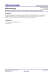
Detecting a Connection to the USB Host
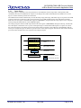
A connection to the USB host is detected using the cable connect interrupt (the BRST bit in the USBIFR0 register).
The cable connect interrupt occurs when a USB device cable is connected to the USB host.
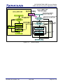
After the user configures the MCU, the sample program pulls up the USB data bus D+ pin using the general output
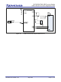
port. The USB host recognizes that a USB device is connected by the pull-up. Figure 2.1 shows an operation flowchart
of the sample program, and Figure 2.2 shows the USB Function Module Peripheral Block Circuit.
USB Function (Hardware)
Sample Program (Software)
Main processing started
Sets CPG
Cable is not connected
VBUS = 0
UDC core is reset
Configures the MCU
Sets BSC
InitMemory
Initializes the memory
Sets I/O PORT
USB cable is connected
Sets PFC
USBPND pin (PB10)
InitSystem
Initializes the USB module
Sets clock in the
USB module
No
Pulls up D+ pin
Main loop
Yes
Sets the interrupt level
Connects a cable
Releases the UDC core reset
Receives bus reset
USBIFR0/BRSY = 1
Bus reset interrupt
SetUsbModule
Pull-up enabled
D+ pin (PB10) High
USBIFR0/BRST interrupt
Interrupt started
ActBusReset
Waits for receiving
the setup command
Clears buffer in software
Clears the bus reset flag
USBIFR0/BRSY = 0
Clears all buffers
Interrupt completed
Figure 2.1
REJ05B1152-0100/Rev.1.00
Detecting a Connection to the USB Host
May 2008
Page 4 of 35
SH7285/SH7286 USB Function Module
USB to Serial Conversion Application Note
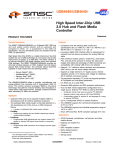
Figure 2.2
REJ05B1152-0100/Rev.1.00
USB Function Module Peripheral Block Circuit
May 2008
Page 5 of 35
SH7285/SH7286 USB Function Module
USB to Serial Conversion Application Note
2.4
Control Transfer
A control transfer is a USB transfer that uses the endpoint 0 default pipe and must be supported by all USB devices.
The USB host issues a USB standard request to the USB device and configures the device. A control transfer can be
used to issue a class- or vendor-specific request.
A control transfer is composed of a Setup stage, Data stage (not in all cases), and Status stage. The Data stage consists
of multiple bus transactions. Control transfers are supported via bi-directional communication flow, according to the
data direction of the Data stage. A control OUT transfer is the data flow from the USB host to the USB device during
the Data stage. A control IN transfer is the data flow from the USB device to the USB host during the Data stage. The
Data stage is completed when the USB host transmits an inverted token of the data direction. The Status stage is the
stage that transmits the inverted token to the USB host. Figure 2.3 shows Data Direction During the Data Stage and
Figure 2.4 shows each Stage Configuration During Control Transfer.
Figure 2.3
Figure 2.4
REJ05B1152-0100/Rev.1.00
Data Direction During the Data Stage
Stage Configuration During Control Transfer
May 2008
Page 6 of 35
SH7285/SH7286 USB Function Module
USB to Serial Conversion Application Note
The USB function module decodes the request, and automatically processes the Data stage and Status stage according
to the USB standard request. However, some USB standard requests, class requests, and vendor requests should be
executed by the software.
The sample program executes the Get Descriptor command, which is the USB standard request to be processed by the
software. To convert USB communication into serial communication, the sample program executes USB
communication class requests. Table 2.3 lists USB Commands and Processing in the Sample Program.
When the sample program receives a USB command that it does not support, it returns a STALL handshake.
Table 2.3
USB Command
Clear Feature
Get Configuration
Get Interface
Get Status
Set Address
Set Configuration
Set Feature
Set Interface
Get Descriptor
Set Line Coding
Set Control Line State
Send Break
Get Line Coding
Other USB commands
USB Commands and Processing in the Sample Program
Type
USB
standard
request
Processing in the Sample Program
The hardware decodes the command, and executes the Data
stage and the Status stage automatically. The software does
nothing.
USB
The software decodes the command, and executes the Data
communication
stage and the Status stage.
class
request
The software returns a STALL handshake.
REJ05B1152-0100/Rev.1.00
May 2008
Page 7 of 35
SH7285/SH7286 USB Function Module
USB to Serial Conversion Application Note
2.4.1
Setup Stage
The Setup stage is composed of one setup transaction. The USB host sends a setup token or data packet (USB
command), then returns a handshake in response to the data packet (USB command) that the USB device received.
Figure 2.5 shows the Setup Transaction Flowchart.
The USB function module automatically executes the Setup stage, Data stage, and Status stage in response to the USB
requests (with some exceptions). If the received request is not a USB standard request, the USB function module
holds the received request in the EP0S data register (USBEPDR0S), and generates the setup request receive complete
interrupt using the SETUPTS bit in the USBIFR0 register.
The sample program reads the USB request held in the data register (USBEPDR0S) during the interrupt, and decodes
the USB request to determine how to process subsequent stages. If the decoded USB request is a request to execute
the control IN transfer, the sample program writes the first data to transfer to the USB host in the EP0iFIFO and the
interrupt is completed. Figure 2.6 shows an operation chart of the sample program. The function (DecComCommand)
processes USB communication class requests in the sample program.
Idle
SETUP
Token
DATA0
Data (USB command)
Handshake
ACK
Idle
Packet issued by the host
Packet issued by the device
Figure 2.5
REJ05B1152-0100/Rev.1.00
Setup Transaction Flowchart
May 2008
Page 8 of 35
SH7285/SH7286 USB Function Module
USB to Serial Conversion Application Note
Sample Program (Software)
(USBIFR0 interrupt)
USB Function (Hardware)
Executes the ActControl
function in the USBIFR0
interrupt handler.
Receives the EP0 setup token
Interrupt started
ActControl started
Receives a command in EP0S
ActControl handles
subsequently
Hardware processes each
Yes
stage automatically.
Processed by hardware
automatically?
Completed
Clears the setup request
receive complete flag
No
USBIFR0/SETUPTS
interrupt
Sets the setup request
receive complete flag
GetPacket
Acquires a USB command
Completed
Sets the EP0S read complete flag
EP0sRDFN = 1
DecStandardCommand
Yes
DecComCommands
- Set Line Coding,
- Set Control Line State,
- Send Break
- Get line Coding
Only these commands are
decided to be handled.
Class-specific command
to be handled?
Decided by bit 6 and
5 in bmRequest
Class-specific
command?
No
Only GetDescriptor
command is decided
to be handled.
Yes
No
No
Standard command
to be handled?
Yes
Sets the state as STALL
EpInfo[0].PresentState = STALL
Prepares GetDescriptor data
Yes
State is STALL?
EpInfo[0].PresentState
is STALL?
OUT (Host to device)
No
Decided by bit 7 in
bmRequest
Transfer direction?
IN (Device to host)
Disables interrupt
Sets the state as TRANS_OUT
Sets the state as TRANS_IN
Sets STALL
USBEPSTL/EP0STL = 1
Sets the interrupt enable bit
for control OUT transfer
EP0iTS = EP0oTS = EP0iTR = 1
Sets the interrupt enable bit
for control IN transfer
EP0iTS = EP0oTS = 1
PutPacket
Writes data in FIFO
Interrupt completed
Figure 2.6
REJ05B1152-0100/Rev.1.00
Setup Stage
May 2008
Page 9 of 35
SH7285/SH7286 USB Function Module
USB to Serial Conversion Application Note
2.4.2
Data Stage
The Data stage of the control IN transfer is composed of single or multiple data transactions. This is called “Data IN
stage processing”. The Data stage of the control OUT transfer is composed of one data OUT transaction. This is
called “Data OUT stage processing”.
(1) Data IN Stage
First, the USB host sends an IN token. When the USB device receives the IN token, it sends a data packet to the USB
host and waits for an ACK handshake from the USB host. If the USB device cannot send a data packet when it
receives the IN token, it returns a NAK handshake to the USB host. Figure 2.7 shows the data IN transaction
flowchart.
When the USB function module receives an IN token without valid data in the EP0iFIFO, it automatically returns a
NAK handshake to the USB host. When the module receives an IN token with valid data in the EP0iFIFO, it sends the
data in the EP0iFIFO to the USB host and waits for an ACK handshake from the USB host. When the USB function
module receives an ACK handshake, it generates the data transmit complete interrupt using the EP0iTS bit in the
USBIFR0 register. On the contrary, when the module receives an OUT token that indicates the Data IN stage has been
completed, it generates the data receive complete interrupt using the EP0oTS bit in the USBIFR0 register.
The sample program identifies the type of the interrupt while it is being processed. When it is the data receive
complete interrupt (the EP0oTS bit in the USBIFR0 register), the sample program advances to the Status stage. When
it is the data transmit complete interrupt (the EP0iTS bit in the USBIFR0 register), data that should be sent to the USB
host is written in the EP0iFIFO, and the sample program waits for the next interrupt. Figure 2.8 shows an operation
flowchart of the Data IN stage by the sample program.
Idle
Token
IN token
DATA0/1
NAK
STALL
Data
Handshake
ACK
Packet issued by the host
Idle
Packet issued by the device
Figure 2.7
REJ05B1152-0100/Rev.1.00
Data IN Transaction
May 2008
Page 10 of 35
SH7285/SH7286 USB Function Module
USB to Serial Conversion Application Note
Figure 2.8
REJ05B1152-0100/Rev.1.00
Data IN Stage (Control IN Transfer)
May 2008
Page 11 of 35
SH7285/SH7286 USB Function Module
USB to Serial Conversion Application Note
(2) Data OUT Stage
The USB host sends an OUT token and a data packet. The USB device receives the OUT token first, then receives the
data packet, and then returns an ACK handshake. When the USB device cannot receive the data packet after it
receives the OUT token, it ignores subsequent data packets, and returns a NAK handshake. When the USB host
receives a NAK handshake, it tries to resend the OUT token and data packet. Figure 2.9 shows the Data OUT
Transaction flowchart.
When the USB function module cannot receive data packets, when it receives the OUT token, it automatically
discards the subsequent data packet and returns a NAK handshake to the USB host. When it receives the OUT token
when it can accept data, it holds the data packet from the USB host in the EP0oFIFO and returns an ACK handshake
to the USB host. After the USB function module transmits an ACK handshake, it generates the data receive complete
interrupt using the EP0oTS bit in the USBIFR0 register. When the function module receives the IN token that
indicates the Data OUT stage is completed, it generates the IN token receive interrupt using the EP0iTR bit in the
USBIFR0 register.
The sample program identifies the type of the interrupt while it is being processed. When it is not the data receive
complete interrupt (the EP0oTS bit in the USBIFR0 register), the sample program advances to the Status stage. When
it is the data receive complete interrupt (the EP0oTS bit in the USBIFR0 register), the sample program reads data in
the EP0oFIFO, sets the EP0oFIFO read complete bit, and waits for the next interrupt to be generated. Figure 2.10
shows an operation flowchart of Data OUT stage by the sample program.
Idle
Token
OUT token
DATA0/1
Data
ACK
NAK
STALL
NYET
Handshake
Packet issued by the host
Idle
Packet issued by the device
Figure 2.9
REJ05B1152-0100/Rev.1.00
Data OUT Transaction
May 2008
Page 12 of 35
SH7285/SH7286 USB Function Module
USB to Serial Conversion Application Note
Figure 2.10
REJ05B1152-0100/Rev.1.00
Data OUT Stage (Control OUT Transfer)
May 2008
Page 13 of 35
SH7285/SH7286 USB Function Module
USB to Serial Conversion Application Note
2.4.3
Status Stage
The direction of the data transaction in the Status stage differs from that of the Data stage; the data OUT transaction is
executed during the Status stage of the control IN transfer, and the data OUT transaction is executed during the Status
stage of the control OUT transfer.
(1) Status Stage of the Control IN Transfer
The USB host sends an OUT token and a 0-byte data packet. The USB device first receives the OUT token and then
receives the 0-byte data packet. Then, it returns an ACK handshake to the USB host.
The USB function module receives the OUT token and the 0-byte data packet, and automatically sends an ACK
handshake to the USB host. Then, the USB function module generates the data receive complete interrupt using the
EP0oTS bit in the USBIFR0 register.
The sample program sets the EP0oFIFO read complete bit (USBTRG/EP0oRFDN) during an interrupt to wait for the
next interrupt. Figure 2.11 shows an operation flowchart of the control IN transfer by the sample program.
Figure 2.11
REJ05B1152-0100/Rev.1.00
Status Stage (Control IN Transfer)
May 2008
Page 14 of 35
SH7285/SH7286 USB Function Module
USB to Serial Conversion Application Note
(2) Status Stage of the Control OUT Transfer
The USB host sends an IN token. The USB device sends a 0-byte data packet to the USB host after it receives the IN
token. Then, the USB device waits for an ACK handshake from the USB host.
When the USB function module receives the IN token, it generates the IN token receive interrupt using the EP0iTR
bit in the USBIFR0 register. When the USB function module receives an IN token although there is no valid 0-byte
data packet in the EP0iFIFO, it automatically returns a NAK handshake to the USB host. When the USB function
module has a valid 0-byte data packet in the EP0iFIFO when it receives the IN token, it sends a 0-byte data packet to
the USB host and waits for an ACK handshake from the USB host. When the USB function module receives the ACK
handshake, it generates the data transmit complete interrupt using the EP0iTS in the USBIFR0 register.
The sample program identifies the type of the interrupt while it is being processed. When it is the data transmit
complete interrupt generated by the EP0iTS in the USBIFR0 register, the sample program clears the interrupt to
complete the control transfer. When it is the IN token receive interrupt generated by the EP0iTR bit in the USBIFR0
register, the sample program enables 0-byte data in the EP0iFIFO by setting the EP0iPKTE bit in the USBTRG
register to 1, and waits for the next interrupt to be generated. Figure 2.12 shows an operation flowchart of the Status
Stage (Control OUT Transfer) by the sample program. When the command is a USB communication class command
(Set Line Coding), the sample program uses a SciInit function to process the command.
Sample Program (Software)
(USBIFR0 interrupt)
USB Function (Hardware)
Receives the EP0 IN token
IN token receive interrupt
USBIFR0/EP0iTR interrupt
Executes ActControlOut
function in the USBIFR0
interrupt handler.
By EP0iPKTE bit
No
Any valid data in the
EP0iFIFO?
Interrupt started
Yes
ActControl Out
Sends a 0-byte data to
the USB host
Yes
EP0i transmit complete
interrupt? (USBIFR0/EP0iTS)
NAK
Returns NAK to the
USB host
Sets the EP0i transmit
complete flag
(USBIFR0/EP0iTS = 1)
Clears EP0i transmit
complete flag
(USBIFR0/EP0iTS = 0)
No
Waits for ACK
USBIFR0/EP0iTS
interrupt
SetControlOutContents
USBTRG/EP0iPKTE = 1
Changes the state
as WAIT
Data in EP0iFIFO is
enabled by EP0iPKTE = 1.
Completed
Disables EP0i transfer
request interrupt
(USBIER0/EP0iTR = 0)
Clears EP0i transfer
request flag
(USBIFR0/EP0iTR = 0)
USB command is
Set Line Coding?
No
Yes
Initializes SCIF
SciInit
Interrupt completed
Figure 2.12
REJ05B1152-0100/Rev.1.00
Status Stage (Control OUT Transfer)
May 2008
Page 15 of 35
SH7285/SH7286 USB Function Module
USB to Serial Conversion Application Note
2.5
Bulk Transfer
A bulk transfer is used to communicate large amounts of data between the USB host and the USB device. Bulk
transfers are supported via bi-directional communication flow, according to the data direction. A bulk OUT transfer is
the data flow from the USB host to the USB device, and a bulk IN transfer is the data flow from the USB device to the
USB host. Figure 2.13 shows data directions of the bulk IN and bulk OUT transfers.
Figure 2.13
REJ05B1152-0100/Rev.1.00
Bulk Transfer
May 2008
Page 16 of 35
SH7285/SH7286 USB Function Module
USB to Serial Conversion Application Note
2.5.1
Bulk OUT Transfer
A bulk OUT transfer is composed of single or multiple OUT transactions. The USB host sends an OUT token and a
data packet in the OUT transaction. The USB device receives the out token first, then receives the data packet, and
then returns an ACK handshake. When the USB device receives the OUT token although it is unable to receive data
packets, it ignores subsequent data packets and returns a NAK handshake. When the USB host receives a NAK
handshake, it attempts to resend the OUT token and data packet to the USB device. Figure 2.14 shows the OUT
Transaction flowchart.
When the USB function module receives an OUT token although it is unable to receive data packets, it automatically
discards subsequent data packets and returns a NAK handshake to the USB host. When the USB function module
receives an OUT token when it can accept data packets, it holds the data from the USB host in the EP1FIFO and
returns an ACK handshake to the USB host. Then, the USB function module generates the data receive complete
interrupt using the EP1FULL bit in the USBIFR0 register.
The sample program reads the data in the EP1FIFO and stores it in the bulk OUT transfer RAM during the interrupt,
sets the EP1 read complete flag (by setting the EP1RDFN bit in the USBTRG register to 1), and waits for the next
interrupt to be generated. When the interrupt is generated, if there is no area in the EP1FIFO to store data, the sample
program disables the EP1FULL interrupt, and the interrupt process is completed while it is in a suspended state. When
serial communication is used to create an area in the bulk OUT transfer RAM, enabling the EP1FULL interrupt
causes the suspended EP1FULL interrupt to be generated, and moves the data in the EP1FIFO to the bulk OUT
transfer RAM during the interrupt, and sets the EP1 read complete flag to wait for the next interrupt to be generated.
Idle
Token
OUT token
DATA0/1
Data
ACK
NAK
STALL
NYET
Handshake
Packet issued by the host
Idle
Packet issued by the device
Figure 2.14
REJ05B1152-0100/Rev.1.00
OUT Transaction
May 2008
Page 17 of 35
SH7285/SH7286 USB Function Module
USB to Serial Conversion Application Note
Figure 2.15
REJ05B1152-0100/Rev.1.00
Bulk OUT Transfer
May 2008
Page 18 of 35
SH7285/SH7286 USB Function Module
USB to Serial Conversion Application Note
2.5.2
Bulk IN Transfer
A bulk IN transfer consists of single or multiple transactions. The USB host sends an IN token in the IN transaction.
When the USB device receives the IN token, it sends a data packet to the USB host and waits for an ACK handshake
from the USB host. When the USB device receives the IN token although it is unable to send data packets, it returns a
NAK handshake to the USB host. Figure 2.16 shows the IN Transaction flowchart.
When the USB function module receives an IN token although there is no valid data in the EP2FIFO, it automatically
returns a NAK handshake to the USB host. The USB function module determines if there is any valid data in the
EP2FIFO using the EP2PKTE bit in the USBTRG register. When the module receives the IN token when there is
valid data in the EP2FIFO, the USB function module sends the data in the EP2FIFO to the USB host and waits for an
ACK handshake from the USB host. When the ACK handshake is received, the USB function module sets the data
transmit complete flag using the EP2EMPTY bit in the USBIFR0 register.
The sample program periodically transfers data in bulk transfer mode within the main loop. When the serial
communication generates data in the bulk IN transfer RAM that should be transmitted to the USB host, the sample
program confirms if the EP2FIFO is empty. When the EP2FIFO is empty, the sample program writes the data in the
EP2FIFO, sets the PE2PKTE bit to 1, and enables the data in the EP2FIFO. When the EP2FIFO is not empty, the
sample program is idle and waits for the USB function module to finish transferring data to the USB host.
Idle
Token
IN token
DATA0/1
NAK
STALL
Data
Handshake
ACK
Packet issued by the host
Idle
Packet issued by the device
Figure 2.16
REJ05B1152-0100/Rev.1.00
IN Transaction
May 2008
Page 19 of 35
SH7285/SH7286 USB Function Module
USB to Serial Conversion Application Note
Figure 2.17
REJ05B1152-0100/Rev.1.00
Bulk IN Transfer
May 2008
Page 20 of 35
SH7285/SH7286 USB Function Module
USB to Serial Conversion Application Note
3.
3.1
USB to Serial Conversion System Using the USB Function Module
Overview
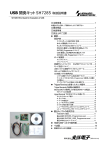
The sample program converts USB to serial using the USB function module and the serial communication interface
embedded in the SH7285 MCU. To transfer keyboard-input characters, text files, or binary files, activate the terminal
software both on the USB host (a computer in this case), and on the serial device. For example, some characters are
input using the keyboard of the USB host, and the characters are transferred to the serially connected device. On the
other hand, some characters are input using keyboard of the serially connected device for transfer to the USB host.
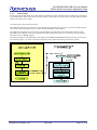
A system configuration of the USB to serial conversion is shown in Figure 3.1, and Table 3.1 lists its specifications.
Figure 3.1
REJ05B1152-0100/Rev.1.00
System Configuration
May 2008
Page 21 of 35
SH7285/SH7286 USB Function Module
USB to Serial Conversion Application Note
Table 3.1 Specifications
Features
Description
Detect a connection to the USB host After the hardware detects a connection, the port pulls up the D+ pin.
• Decode requests, processes the Data stage and Status stage of
the USB request transmitted from the USB host in the control
transfer.
• Sends the descriptor information shown in Figure 3.2 through
Figure 3.4 to Get Descriptor command to connect with the USB
host PC as a USB communication class.
• Descriptor samples to send to the USB host are shown in the
SetUsbInfo.h file. Figure 3.2 shows the device descriptor sample,
Figure 3.3 and Figure 3.4 shows the configuration descriptor
samples. Table 3.2 lists Vendor ID and Product ID of the sample.
Control transfer
(USB standard request)
Executes the following USB communication class commands:
Control transfer
Get Line Coding, Set Line Coding, Set Control Line State, and Send
(USB communication class request)
Break
Bulk IN/OUT transfer
Executes the bulk IN/OUT transfer.
Serial/USB communication
conversion
(1) Sends the received data from the USB host in bulk OUT transfer
to the serial device by serial OUT communication.
(2) Sends the received data from the serial device by serial IN
communication to the USB host in bulk IN transfer.
/*
/*
Descriptor Information */
Device Descriptor
*/
unsigned char
DeviceItem[] = {
0x12,0x01,0x10,0x01,
0x02,
/* Communication Class */
0x00,0x00,0x08,
0x5B,
/* Vendor = Renesas Technology */
0x04,
/*
""Attention"" Please use your company Vendor ID
0x20,
/* Product ID 0x0020 */
0x00,0x00,0x01,0x00,0x00,
0x03,
/* Strings Descriptor iSerialNumber */
0x01
};
*/
DeviceType
deviceDiscriptorGVar[] = {
{18,DeviceItem}
};
Figure 3.2
Device Descriptor Sample
Note:
Table 3.2 lists the default value of the vendor ID and product ID in the device descriptor sample. These values MUST
be changed when applied to the user system.
Table 3.2
ID
Vendor ID
Product ID
REJ05B1152-0100/Rev.1.00
Vendor ID and Product ID Sample
Value
0x045B
0x0020
Description
Renesas Technology
Renesas SH7285 Serial-USB
May 2008
Page 22 of 35
SH7285/SH7286 USB Function Module
USB to Serial Conversion Application Note
/*
Configuration Descriptor
*/
/*
Configuration Descriptor informations , Data length = 67Byte
*/
unsigned char
configurationItem[] = {
/* Configuration Descriptor */
0x09,
/*
0:bLength */
0x02,
/*
1:bDescriptorType */
0x43,
/*
2:wTotalLength(L) */
/* 43'h (=67) */
0x00,
/*
3:wTotalLength(H) */
0x02,
/* 4:bNumInterfaces */
0x01,
/* 5:bConfigurationValue */
0x00,
/* 6:iConfiguration */
0xC0,
/*
7:bmAttributes */
/* self powered */
0x10,
/*
8:MAXPower */
/* Interface Descriptor 1-0-0 [Communication Class] */
0x09,
/*
0:bLength */
0x04,
/*
1:bDescriptor */
0x00,
/*
2:bInterfaceNumber */
0x00,
/*
3:bAlternateSetting */
0x01,
/* 4:bNumEndpoints */ /* support INT IN (= EP3) */
0x02,
/* 5:bInterfaceClass */
/* Communication Interface Class */
0x02,
/* 6:bInterfaceSubClass */
/* Abstruct Control Model */
0x01,
/* 7:bInterfaceProtocol */
/* Common AT commands */
0x00,
/*
8:iInterface */
/* Class-Specific Configuration Descriptors */
/* Header Functional Descriptor */
0x05,
/* 0:length of this desc. */
0x24,
/* 1:CS_INTERFACE */
0x00,
/* 2:Header Functional Descr. */
0x10,
/* 3:bcdCDC Rel. 1.10 */
0x01,
/* 4:bcdCDC Rel. 1.10 */
/* Abstract Control Management Functional Descriptor */
0x04,
/* 0:length of this desc. */
0x24,
/* 1:CS_INTERFACE */
0x02,
/* 2:Abstr.Contr.Managm. F.D. */
0x06,
/* 3:bmCapabilities */
/* support Send Break, Set Line Coding,
Set Control Line State, Get Line Coding */
/* Union Functional Descriptor */
0x05,
/* 0:length of this desc. */
0x24,
/* 1:CS_INTERFACE */
0x06,
/* 2:Union Functional Descr. */
0x00,
/* 3:bMasterInterface */
0x01,
/* 4:bSlaveInterface0 */
/* Call Management Functional Descriptor */
0x05,
/* 0:length of this desc. */
0x24,
/* 1:CS_INTERFACE */
0x01,
/* 2:Call Managment F.D. */
0x03,
/* 3:bmCapabilities */
0x01,
/* 4:bDataInterface */
/* Endpoint Descriptor 1-0-0-0 */
0x07,
/* 0:bLength */
0x05,
/* 1:bDescriptorType */
0x83,
/* 2:bEndpointAddress */
0x03,
/* 3:bmAttribute */
0x08,
/* 4:wMAXPacketSize_lo */
0x00,
/* 5:wMAXPacketSize_hi */
0x10,
/* 6:bInterval */
Figure 3.3
REJ05B1152-0100/Rev.1.00
/* IN, number = 3 */
Configuration Descriptor Sample (1/2)
May 2008
Page 23 of 35
SH7285/SH7286 USB Function Module
USB to Serial Conversion Application Note
/* Interface Descriptor 1-1-0 [Data Class Interface] */
0x09,
/* 0:bLength */
0x04,
/* 1:bDescriptor */
0x01,
/* 2:bInterfaceNumber */
0x00,
/* 3:bAlternateSetting */
0x02,
/* 4:bNumEndpoints */ /* support Bulk OUT (= EP1) and Bulk IN (= EP2) */
0x0A,
/* 5:bInterfaceClass */ /* Data Interface Class */
0x00,
/* 6:bInterfaceSubClass */
/* unuse */
0x00,
/* 7:bInterfaceProtocol */ /* USB */
0x00,
/* 8:iInterface */
/* Endpoint Descriptor 1-1-0-0 */
0x07,
/* 0:bLength */
0x05,
/* 1:bDescriptorType */
0x01,
/* 2:bEndpointAddress */
0x02,
/* 3:bmAttribute */
0x40,
/* 4:wMAXPacketSize_lo */
0x00,
/* 5:wMAXPacketSize_hi */
0x00,
/* 6:bInterval */
/* Endpoint Descriptor 1-1-0-1 */
0x07,
/* 0:bLength */
0x05,
/* 1:bDescriptorType */
0x82,
/* 2:bEndpointAddress */
0x02,
/* 3:bmAttribute */
0x40,
/* 4:wMAXPacketSize_lo */
0x00,
/* 5:wMAXPacketSize_hi */
0x00
/* 6:bInterval */
};
ConfigurationType
configurationDiscriptorGVar[] = {
{67,configurationItem}
};
Figure 3.4
REJ05B1152-0100/Rev.1.00
Configuration Descriptor Sample (2/2)
May 2008
Page 24 of 35
SH7285/SH7286 USB Function Module
USB to Serial Conversion Application Note
3.2
Operation Flowchart
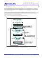
The sample program enters the main loop after initial settings are completed.
When the sample program receives a data packet from the serial device in serial IN communication, it stores the
received packet in the bulk IN transfer RAM. The stored data is transmitted to the USB host in a bulk IN transfer. For
details on bulk IN transfer, refer to 2.5.2 Bulk IN Transfer. For details on serial IN communication, refer to 3.3.2
Serial IN Communication.
When the sample program receives a data packet from the USB host in a bulk OUT transfer, it stores the received data
packet in the bulk OUT transfer RAM. The stored data is transmitted to the serial device in the serial OUT
communication. For details on the bulk OUT transfer, refer to 2.5.1 Bulk OUT Transfer. For details on serial OUT
communication, refer to 3.3.1 Serial OUT Communication.
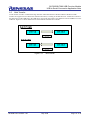
Figure 3.5 shows an Operation Flowchart and Figure 3.6 shows the Data Flow.
Figure 3.5
REJ05B1152-0100/Rev.1.00
Operation Flowchart
May 2008
Page 25 of 35
SH7285/SH7286 USB Function Module
USB to Serial Conversion Application Note
M3A-HS85
sample program
USB host
Serial device
Serial I/F
USB I/F
Serial OUT
communication
Bulk OUT transfer RAM
256 bytes
Bulk OUT transfer
Serial I/F
USB I/F
Bulk IN transfer
Bulk IN transfer RAM
256 bytes
Figure 3.6
REJ05B1152-0100/Rev.1.00
Serial IN
communication
Data Flow
May 2008
Page 26 of 35
SH7285/SH7286 USB Function Module
USB to Serial Conversion Application Note
3.3
Serial Communication
The sample program uses a SCIF module 1 for serial communication. Serial OUT communication is executed only
when there is data in the bulk OUT transfer RAM, and serial IN communication is executed only by the serial receive
interrupt.
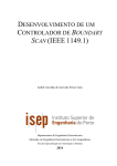
3.3.1
Serial OUT Communication
The sample program uses the ActSerialout function to execute serial OUT communication. Data in the bulk OUT
transfer RAM is serially transmitted in serial OUT communication. When the bulk OUT transfer RAM is sufficiently
empty by the serial OUT communication, the sample program enables the EP1FULL interrupt. When the EP1FULL
interrupt is enabled, the suspended EP1FULL interrupt occurs to transfer data in the bulk OUT transfer. Figure 3.7
shows an operation flowchart of the Serial OUT Communication.
Sample program (Software)
(Serial OUT communication)
Serial OUT communication started
ActSerialOut
Calculates the number of transfer bytes
ExSerialOut
SCSSR_2 TDFE = 1
No
Yes
Writes data to transmit in SCFTDR_2
Clears SCSSR_2 TDFE/TEND
Bulk OUT transfer
is disabled?
No
Yes
The bulk-OUT transfer
RAM is empty?
Serial OUT communication
enables the EP1FULL
interrupt and the suspended
EP1FULL interrupt occurs.
No
Yes
EP1FULL interrupt is enabled
USBIER/EP1FULL = 1
Serial OUT communication completed
Figure 3.7
1
Serial OUT Communication
This is for the M3A-HS85 with the SH7285 MCU. The SCI module is used on the M3A-HS87 with the SH7286 MCU.
REJ05B1152-0100/Rev.1.00
May 2008
Page 27 of 35
SH7285/SH7286 USB Function Module
USB to Serial Conversion Application Note
3.3.2
Serial IN Communication
Serial IN communication is activated by the serial receive interrupt and executed by the ActSerialIn function. The
sample program stores serially-received data in the RAM for the bulk IN transfer. When the RAM is full, the sample
program transmits Xoff in serial communication to disable the serial IN communication. Figure 3.8 shows an operation
flowchart of the Serial IN Communication.
Figure 3.8
REJ05B1152-0100/Rev.1.00
Serial IN Communication
May 2008
Page 28 of 35
SH7285/SH7286 USB Function Module
USB to Serial Conversion Application Note
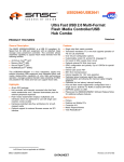
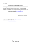
3.4
Setting Environment
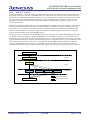
Use an RS-232C serial cable to connect the M3A-HS85 (SH7285 CPU board) to the computer (cross-connect). Then,
use a USB cable to connect the M3A-HS19 to the computer. Figure 3.9 shows the Setting Environment.
Terminal 1
Terminal 2
ABC
DEF
USB to serial conversion
SH7285
Serial
communication
USB
communication
USB host computer
SH7285 CPU board
Figure 3.9
3.4.1
Serial device
Setting Environment
USB Host Computer Setting
After the sample program is written to the M3A-HS85 and is connected to the USB host computer with a USB cable
for the first time, the device driver needs to be installed on the USB host computer. Install the Windows standard USB
communication class device driver (usbser.sys) as the device driver. Figure 3.10 through Figure 3.12 show the INF
files for Windows. These files are used for installation.
;-------------------------------------------------------;
Renesas Technology Corp
;
USB Serial Ports Driver
;
for Windows2000 and WindowsXP
;
29 September 2003
;-------------------------------------------------------[Version]
LayoutFile=layout.inf
Signature="$CHICAGO$"
Class=Ports
ClassGuid={4D36E978-E325-11CE-BFC1-08002BE10318}
Provider=%MyCompany%
DriverVer=29/09/2003,1.0.0.0
[DestinationDirs]
DefaultDestDir=12
[Manufacturer]
%MyCompany%=Models
[ClassInstall]
AddReg=PortsClass.AddReg
Figure 3.10
REJ05B1152-0100/Rev.1.00
INF File Example for Windows (1/3)
May 2008
Page 29 of 35
SH7285/SH7286 USB Function Module
USB to Serial Conversion Application Note
[PortsClass.AddReg]
HKR,,,,%PortsClassName%
[ClassInstall32.NT]
AddReg=PortsClass.NT.AddReg
[PortsClass.NT.AddReg]
HKR,,,,%PortsClassName%
HKR,,Icon,,"-23"
HKR,,Installer32,,"MsPorts.Dll,PortsClassInstaller"
[ControlFlags]
ExcludeFromSelect=*
;**********************************************
; Please change to your company's VID and PID *
;**********************************************
[Models]
%USB.PnP%=ComPort, USB¥VID_045B&PID_0020
/* USB Vendor ID & Product ID */
[ComPort.NT]
CopyFiles=ComPort.Copy
AddReg=ComPort.AddReg, ComPort.NT.AddReg
[ComPort.NT.HW]
AddReg=ComPort.NT.HW.AddReg
[ComPort.NT.Services]
AddService = usbser, 0x00000002, Serial_Service_Inst,
Serial_EventLog_Inst
AddService = Serenum,,Serenum_Service_Inst
[ComPort.NT.HW.AddReg]
HKR,,"UpperFilters",0x00010000,"serenum"
; -------------- USBSerial Port Driver install sections
[Serial_Service_Inst]
DisplayName
= %Serial.SVCDESC%
ServiceType
= 1
; SERVICE_KERNEL_DRIVER
StartType
= 3
; SERVICE_DEMAND_START
ErrorControl
= 1
; SERVICE_ERROR_NORMAL
ServiceBinary = %12%¥usbser.sys
LoadOrderGroup = Extended base
; -------------- Serenum Driver install section
[Serenum_Service_Inst]
DisplayName
= %Serenum.SVCDESC%
ServiceType
= 1
; SERVICE_KERNEL_DRIVER
StartType
= 3
; SERVICE_DEMAND_START
ErrorControl
= 1
; SERVICE_ERROR_NORMAL
ServiceBinary = %12%¥serenum.sys
LoadOrderGroup = PNP Filter
[Serial_EventLog_Inst]
AddReg = Serial_EventLog_AddReg
Figure 3.11
REJ05B1152-0100/Rev.1.00
INF File Example for Windows (2/3)
May 2008
Page 30 of 35
SH7285/SH7286 USB Function Module
USB to Serial Conversion Application Note
[Serial_EventLog_AddReg]
HKR,,EventMessageFile,0x00020000,"%%SystemRoot%%¥System32¥IoLogMsg.dll;%
%SystemRoot%%¥System32¥drivers¥usbser.sys"
HKR,,TypesSupported,0x00010001,7
; COM sections
;---------------------------------------------------------[ComPort.Copy]
usbser.sys,,,0x20
[ComPort.AddReg]
HKR,,PortSubClass,1,01
[ComPort.NT.Copy]
CopyFiles=ComPort.Copy
[ComPort.NT.AddReg]
HKR,,EnumPropPages32,,"MsPorts.dll,SerialPortPropPageProvider"
;**********************************************
; Please change to your company's information *
;**********************************************
[Strings]
MyCompany="Renesas Technology Corp"
DiskName_Desc="Installation Disk"
PortsClassName = "Ports (COM & LPT)"
Serenum.SVCDESC = "Serenum Filter Driver"
Serial.SVCDESC = "USB Serial Ports Driver"
USB.PnP="USB Serial Ports Driver"
Figure 3.12
INF file example for Windows (3/3)
Note:
VID_045B and PID_0020 MUST be changed according to the Vendor ID and Product ID set in the device descriptor.
Table 3.3 shows the default values.
Table 3.3
Value
VID_045B
PID_0020
REJ05B1152-0100/Rev.1.00
Vendor ID and Product ID
Description
Indicates the Vendor ID = 0x045B.
Indicates the Product ID = 0x0020.
May 2008
Page 31 of 35
SH7285/SH7286 USB Function Module
USB to Serial Conversion Application Note
3.4.2
PC-PC Communication Settings
The table below lists the settings for the terminal software.
Table 3.4
Items
Terminal Software Settings
bps (B)
Description
Select the number of ports connected to an RS-232C serial cable or a USB
cable
115200 bps
Data bits (D)
Parity (P)
Stop bit (S)
Flow control(F)
8
None
1
Xon/Xoff
Connection
REJ05B1152-0100/Rev.1.00
May 2008
Page 32 of 35
SH7285/SH7286 USB Function Module
USB to Serial Conversion Application Note
4.
References
Software Manual
SH-1/SH-2/SH-DSP Software Manual Rev. 7.00
Download the latest version from Renesas Technology website.
REJ05B1152-0100/Rev.1.00
May 2008
Page 33 of 35
SH7285/SH7286 USB Function Module
USB to Serial Conversion Application Note
Website and Support
Renesas Technology Website
http://www.renesas.com/
Inquiries
http://renesas.com/inquiry
[email protected]
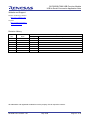
Revision History
Rev.
1.00
Date
2008.05.13
Page
-
Description
Summary
First edition issued
All trademarks and registered trademarks are the property of their respective owners.
REJ05B1152-0100/Rev.1.00
May 2008
Page 34 of 35
SH7285/SH7286 USB Function Module
USB to Serial Conversion Application Note
© 2008. Renesas Technology Corp., All rights reserved.
REJ05B1152-0100/Rev.1.00
May 2008
Page 35 of 35