1
To our customers,
Old Company Name in Catalogs and Other Documents
On April 1st, 2010, NEC Electronics Corporation merged with Renesas Technology
Corporation, and Renesas Electronics Corporation took over all the business of both
companies. Therefore, although the old company name remains in this document, it is a valid
Renesas Electronics document. We appreciate your understanding.
Renesas Electronics website: http://www.renesas.com
April 1st, 2010
Renesas Electronics Corporation
Issued by: Renesas Electronics Corporation (http://www.renesas.com)
Send any inquiries to http://www.renesas.com/inquiry.
Notice
1.
2.
3.
4.
5.
6.
7.
All information included in this document is current as of the date this document is issued. Such information, however, is
subject to change without any prior notice. Before purchasing or using any Renesas Electronics products listed herein, please
confirm the latest product information with a Renesas Electronics sales office. Also, please pay regular and careful attention to
additional and different information to be disclosed by Renesas Electronics such as that disclosed through our website.
Renesas Electronics does not assume any liability for infringement of patents, copyrights, or other intellectual property rights
of third parties by or arising from the use of Renesas Electronics products or technical information described in this document.
No license, express, implied or otherwise, is granted hereby under any patents, copyrights or other intellectual property rights
of Renesas Electronics or others.
You should not alter, modify, copy, or otherwise misappropriate any Renesas Electronics product, whether in whole or in part.
Descriptions of circuits, software and other related information in this document are provided only to illustrate the operation of
semiconductor products and application examples. You are fully responsible for the incorporation of these circuits, software,
and information in the design of your equipment. Renesas Electronics assumes no responsibility for any losses incurred by
you or third parties arising from the use of these circuits, software, or information.
When exporting the products or technology described in this document, you should comply with the applicable export control
laws and regulations and follow the procedures required by such laws and regulations. You should not use Renesas
Electronics products or the technology described in this document for any purpose relating to military applications or use by
the military, including but not limited to the development of weapons of mass destruction. Renesas Electronics products and
technology may not be used for or incorporated into any products or systems whose manufacture, use, or sale is prohibited
under any applicable domestic or foreign laws or regulations.
Renesas Electronics has used reasonable care in preparing the information included in this document, but Renesas Electronics
does not warrant that such information is error free. Renesas Electronics assumes no liability whatsoever for any damages
incurred by you resulting from errors in or omissions from the information included herein.
Renesas Electronics products are classified according to the following three quality grades: “Standard”, “High Quality”, and
“Specific”. The recommended applications for each Renesas Electronics product depends on the product’s quality grade, as
indicated below. You must check the quality grade of each Renesas Electronics product before using it in a particular
application. You may not use any Renesas Electronics product for any application categorized as “Specific” without the prior
written consent of Renesas Electronics. Further, you may not use any Renesas Electronics product for any application for
which it is not intended without the prior written consent of Renesas Electronics. Renesas Electronics shall not be in any way
liable for any damages or losses incurred by you or third parties arising from the use of any Renesas Electronics product for an
application categorized as “Specific” or for which the product is not intended where you have failed to obtain the prior written
consent of Renesas Electronics. The quality grade of each Renesas Electronics product is “Standard” unless otherwise
expressly specified in a Renesas Electronics data sheets or data books, etc.
“Standard”:
8.
9.
10.
11.
12.
Computers; office equipment; communications equipment; test and measurement equipment; audio and visual
equipment; home electronic appliances; machine tools; personal electronic equipment; and industrial robots.
“High Quality”: Transportation equipment (automobiles, trains, ships, etc.); traffic control systems; anti-disaster systems; anticrime systems; safety equipment; and medical equipment not specifically designed for life support.
“Specific”:
Aircraft; aerospace equipment; submersible repeaters; nuclear reactor control systems; medical equipment or
systems for life support (e.g. artificial life support devices or systems), surgical implantations, or healthcare
intervention (e.g. excision, etc.), and any other applications or purposes that pose a direct threat to human life.
You should use the Renesas Electronics products described in this document within the range specified by Renesas Electronics,
especially with respect to the maximum rating, operating supply voltage range, movement power voltage range, heat radiation
characteristics, installation and other product characteristics. Renesas Electronics shall have no liability for malfunctions or
damages arising out of the use of Renesas Electronics products beyond such specified ranges.
Although Renesas Electronics endeavors to improve the quality and reliability of its products, semiconductor products have
specific characteristics such as the occurrence of failure at a certain rate and malfunctions under certain use conditions. Further,
Renesas Electronics products are not subject to radiation resistance design. Please be sure to implement safety measures to
guard them against the possibility of physical injury, and injury or damage caused by fire in the event of the failure of a
Renesas Electronics product, such as safety design for hardware and software including but not limited to redundancy, fire
control and malfunction prevention, appropriate treatment for aging degradation or any other appropriate measures. Because
the evaluation of microcomputer software alone is very difficult, please evaluate the safety of the final products or system
manufactured by you.
Please contact a Renesas Electronics sales office for details as to environmental matters such as the environmental
compatibility of each Renesas Electronics product. Please use Renesas Electronics products in compliance with all applicable
laws and regulations that regulate the inclusion or use of controlled substances, including without limitation, the EU RoHS
Directive. Renesas Electronics assumes no liability for damages or losses occurring as a result of your noncompliance with
applicable laws and regulations.
This document may not be reproduced or duplicated, in any form, in whole or in part, without prior written consent of Renesas
Electronics.
Please contact a Renesas Electronics sales office if you have any questions regarding the information contained in this
document or Renesas Electronics products, or if you have any other inquiries.
(Note 1) “Renesas Electronics” as used in this document means Renesas Electronics Corporation and also includes its majorityowned subsidiaries.
(Note 2) “Renesas Electronics product(s)” means any product developed or manufactured by or for Renesas Electronics.
User’s Manual
M3T-ICC740 V.1.00
User’s Manual
Cross Tool Kit for 740 Family<Included ICC740 of
IAR Systems>
Rev.1.00 2004.07
• Microsoft, MS-DOS, Windows, and Windows NT are registered trademarks of Microsoft Corporation in the U.S. and other countries.
• IBM and AT are registered trademarks of International Business Machines Corporation.
• Intel and Pentium are registered trademarks of Intel Corporation.
• Adobe, Acrobat, and Acrobat Reader are trademarks of Adobe Systems Incorporated.
• All other brand and product names are trademarks, registered trademarks or service marks of their respective holders.
Keep safety first in your circuit designs!
z Renesas Technology Corporation and Renesas Solutions Corporation put the maximum effort into making semiconductor products
better and more reliable, but there is always the possibility that trouble may occur with them. Trouble with semiconductors may lead to
personal injury, fire or property damage. Remember to give due consideration to safety when making your circuit designs, with
appropriate measures such as (i) placement of substitutive, auxiliary circuits, (ii) use of nonflammable material or (iii) prevention
against any malfunction or mishap.
Notes regarding these materials
z These materials are intended as a reference to assist our customers in the selection of the Renesas Technology product best suited to
the customer's application; they do not convey any license under any intellectual property rights, or any other rights, belonging to
Renesas Technology Corporation, Renesas Solutions Corporation or a third party.
z Renesas Technology Corporation and Renesas Solutions Corporation assume no responsibility for any damage, or infringement of any
third-party's rights, originating in the use of any product data, diagrams, charts, programs, algorithms, or circuit application examples
contained in these materials.
z All information contained in these materials, including product data, diagrams, charts, programs and algorithms represents information
on products at the time of publication of these materials, and are subject to change by Renesas Technology Corporation and Renesas
Solutions Corporation without notice due to product improvements or other reasons. It is therefore recommended that customers
contact Renesas Technology Corporation, Renesas Solutions Corporation or an authorized Renesas Technology product distributor
for the latest product information before purchasing a product listed herein. The information described here may contain technical
inaccuracies or typographical errors. Renesas Technology Corporation and Renesas Solutions Corporation assume no responsibility
for any damage, liability, or other loss rising from these inaccuracies or errors. Please also pay attention to information published by
Renesas Technology Corporation and Renesas Solutions Corporation by various means, including the Renesas home page
(http://www.renesas.com).
z When using any or all of the information contained in these materials, including product data, diagrams, charts, programs, and
algorithms, please be sure to evaluate all information as a total system before making a final decision on the applicability of the
information and products. Renesas Technology Corporation and Renesas Solutions Corporation assume no responsibility for any
damage, liability or other loss resulting from the information contained herein.
z Renesas Technology semiconductors are not designed or manufactured for use in a device or system that is used under
circumstances in which human life is potentially at stake. Please contact Renesas Technology Corporation, Renesas Solutions
Corporation or an authorized Renesas Technology product distributor when considering the use of a product contained herein for any
specific purposes, such as apparatus or systems for transportation, vehicular, medical, aerospace, nuclear, or undersea repeater use.
z The prior written approval of Renesas Technology Corporation and Renesas Solutions Corporation is necessary to reprint or reproduce
in whole or in part these materials.
z If these products or technologies are subject to the Japanese export control restrictions, they must be exported under a license from
the Japanese government and cannot be imported into a country other than the approved destination. Any diversion or reexport
contrary to the export control laws and regulations of Japan and/or the country of destination is prohibited.
z Please contact Renesas Technology Corporation or Renesas Solutions Corporation for further details on these materials or the
products contained therein.
For inquiries about the contents of this document or product, fill in the text file the installer generates in the following directory and email
to your local distributor.
\SUPPORT\Product-name\SUPPORT.TXT
Renesas Tools Homepage http://www.renesas.com/en/tools
Contents
PREFACE ................................................................
................................................................................................
................................................................................................
................................................................7
................................7
1.
OVERVIEW................................
OVERVIEW................................................................
................................................................................................
......................................................................................
......................................................8
......................8
2.
INSTALLING TOOLS
TOOLS................................
................................................................
................................................................................................
....................................................................
....................................10
.... 10
3.
STARTING AND QUITTING THE TM ................................................................
.........................................................................
.........................................12
......... 12
4.
3.1.
STARTING THE TM ....................................................................................................... 12
3.2.
REGISTERING THE EDITOR ........................................................................................... 12
3.3.
QUITTING THE TM........................................................................................................ 13
QUICK TOUR ................................................................
................................................................................................
................................................................................
................................................14
................ 14
4.1.
CREATING A NEW PROJECT .......................................................................................... 16
4.2.
COMPLEMENTING A NEW PROJECT .............................................................................. 17
4.3.
CREATING A FILE ......................................................................................................... 18
4.4.
REGISTERING THE FILE ................................................................................................ 18
4.5.
SAVING THE PROJECT ................................................................................................... 19
4.6.
BUILDING A PROJECT ................................................................................................... 20
4.7.
STARTING THE DEBUGGER ........................................................................................... 21
4.8.
DEBUGGING A PROGRAM .............................................................................................. 23
4.8.1.
4.8.2.
4.8.3.
5.
6.
Loading a Program ...........................................................................................................24
Executing up to the main Function..................................................................................24
Confirming Interrupt Generation....................................................................................24
CREATING A NEW PROJECT ................................................................
.....................................................................................
.....................................................25
..................... 25
5.1.
NEW PROJECT .............................................................................................................. 26
5.2.
COMPLEMENTING THE PROJECT .................................................................................. 27
EDITING THE PROJECT ................................................................
.............................................................................................
.............................................................29
.............................29
6.1.
EDITING CSTARTUP.S31 ................................................................................................ 29
6.1.1.
6.1.2.
6.2.
Changing the Stack Page .................................................................................................29
Changing the Interrupt Vector Area ...............................................................................29
EDITING THE LNK740.XCL FILE ..................................................................................... 30
6.2.1.
6.2.2.
6.2.3.
6.2.4.
6.2.5.
6.2.6.
Changing the Stack Area .................................................................................................30
Changing the Beginning Address of Page 0 ....................................................................31
Changing the Ending Address of Page N ........................................................................31
Changing the ROM Area Address ...................................................................................32
Changing the Interrupt Vector Area ...............................................................................32
Changing the Library.......................................................................................................33
3
6.3.
CHANGING THE ICC740 OPTIONS ................................................................................ 34
6.3.1.
6.3.2.
6.3.3.
6.4.
CHANGING THE A740 OPTIONS .................................................................................... 37
6.4.1.
6.4.2.
6.5.
7.
Changing the Processor Group ........................................................................................35
Changing the Memory Model...........................................................................................36
Changing the Optimization Level ...................................................................................36
Changing the Processor Group ........................................................................................37
Changing the Memory Model...........................................................................................38
CHANGING THE XLINK OPTIONS ................................................................................ 39
DEVELOPING A PROJECT ................................................................
..........................................................................................
..........................................................40
..........................40
7.1.
CREATING AND REGISTERING THE SOURCE FILES ....................................................... 40
7.2.
ALTERING THE LNK740.XCL FILE .................................................................................. 41
8.
BUILDING A PROJECT
PROJECT................................
................................................................
................................................................................................
................................................................42
................................ 42
8.1.
ERRORS IN THE C COMPILER ICC740 AND THE ASSEMBLER A740.............................. 42
8.2.
ERRORS IN THE LINKER XLINK................................................................................... 43
8.3.
SETTING OPTIONS IN SOURCE FILE UNITS .................................................................. 45
9.
10.
DEBUGGING A PROJECT ................................................................
...........................................................................................
...........................................................46
...........................46
CREATING A HEX FILE ................................................................
...........................................................................................
...........................................................48
........................... 48
4
Figure of Contents
FIGURE 1 PROCEDURE FOR INSTALLING THE M3T-ICC740 ........................................................ 11
FIGURE 2 PROJECT BAR .............................................................................................................. 12
FIGURE 3 PROJECT BAR PASTED AT THE TOP .............................................................................. 12
FIGURE 4 TOOLS INFORMATION DIALOG BOX .............................................................................. 12
FIGURE 5 CONTEXT MENU DISPLAYED BY RIGHT-CLICKING ........................................................ 13
FIGURE 6 NEW PROJECT BUTTON IN THE PROJECT BAR ............................................................ 16
FIGURE 7 PROJECT EDITOR ......................................................................................................... 16
FIGURE 8 COMPLEMENTING A NEW PROJECT .............................................................................. 17
FIGURE 9 REGISTERING A SOURCE FILE ...................................................................................... 19
FIGURE 10 SAVE BUTTON OF THE PROJECT EDITOR ................................................................... 19
FIGURE 11 BUILD, REBUILD AND PARTIAL BUILD BUTTONS IN THE PROJECT BAR .................... 20
FIGURE 12 BUILDER .................................................................................................................... 20
FIGURE 13 START DEBUGGER BUTTON IN THE PROJECT BAR ..................................................... 21
FIGURE 14 DEBUG TOOL TAB OF THE TOOLS INFORMATION DIALOG BOX ............................... 21
FIGURE 15 REGISTERING DEBUGGERS ........................................................................................ 22
FIGURE 16 M3T-PD38SIM ......................................................................................................... 23
FIGURE 17 INIT DIALOG BOX OF THE M3T-PD38SIM ................................................................. 23
FIGURE 18 PROJECT BAR ............................................................................................................ 26
FIGURE 19 PROJECT EDITOR ....................................................................................................... 26
FIGURE 20 REGISTERING THE LNK740.XCL FILE .......................................................................... 28
FIGURE 21 LAUNCHING THE OPTION BROWSER .......................................................................... 34
FIGURE 22 OPTION BROWSER DIALOG BOX ................................................................................. 34
FIGURE 23 OPTIONS DIALOG BOX FOR THE ICC740 .................................................................... 35
FIGURE 24 SELECTING TARGET FOR THE CATEGORY AND THE SELECT OPTIONS DIALOG BOX ... 35
FIGURE 25 CHANGING THE OPTIMIZATION LEVEL IN THE SELECT OPTION DIALOG BOX.............. 36
FIGURE 26 OPTIONS DIALOG BOX FOR THE A740 ........................................................................ 37
FIGURE 27 EDITOR START BUTTON IN THE PROJECT BAR ........................................................... 40
FIGURE 28 REGISTERING A SOURCE FILE .................................................................................... 40
FIGURE 29 BUILD BUTTONS LOCATED IN THE PROJECT BAR....................................................... 42
FIGURE 30 SETTING OPTIONS IN SOURCE FILE UNITS IN THE OPTION BROWSER DIALOG BOX .... 45
FIGURE 31 DEBUG BUTTON IN THE PROJECT BAR....................................................................... 46
FIGURE 32 DEBUG TOOL TAB OF THE TOOL INFORMATION DIALOG BOX................................. 46
FIGURE 33 PROJECT PROPERTIES DIALOG BOX ........................................................................... 48
FIGURE 34 OPTION BROWSER DIALOG BOX WITH XLINK(LMC) REGISTERED ............................... 48
5
Teble of Contents
TABLE 1 NEW PROJECT WIZARD EXECUTION STEPS ................................................................... 16
TABLE 2 PROCESSOR GROUP, MEMORY MODEL AND STACK AREA ............................................. 25
TABLE 3 FILES AND OPTIONS TO ALTER ...................................................................................... 25
TABLE 4 NEW PROJECT WIZARD EXECUTION STEPS ................................................................... 27
TABLE 5 NEW FILES CREATED IN THE WORKING DIRECTORY .................................................... 27
TABLE 6 ITEMS TO EDIT IN CSTARTUP.S31................................................................................... 29
TABLE 7 ITEMS TO EDIT IN LNK740.XCL ....................................................................................... 30
TABLE 8 PROCESSOR GROUP, MEMORY MODEL AND LIBRARY ................................................... 33
TABLE 9 ICC740 OPTIONS .......................................................................................................... 34
TABLE 10 DEFAULT OPTIONS OF THE A740 ................................................................................ 37
TABLE 11 DEFAULT OPTIONS OF XLINK (COMMAND LINE)....................................................... 39
TABLE 12 DEFAULT OPTIONS OF XLINK(LMC) (COMMAND LINE)................................................ 49
6
Preface
Before reading this user’s manual, please read the release notes included with your product.
Product configuration, product handling, precautions and other important information are written
in it.
Target reader
This user’s manual is written for:
• Those who have experience in developing and debugging embedded application programs
in C language
• Those who use Renesas’s integrated development environment for the first time
Reference manuals
For more information about the terms used and the functions of Renesas’s integrated
development environment (called TM) and details on how to use it, please refer to the
manual given below. This manual can also be consulted on-line.
TM V.3.20A User’s Manual (included with TM V.3.20A)
For more information about the terms used and the functions of the C compiler ICC740
from LAR Systems (hereafter referred to as the ICC740), and for details on how to use it,
please refer to the PDF manual included with the ICC740.
7
1. Overview
The M3T-ICC740 is a cross tool kit for the 740 family of Renesas 8-bit microcomputers.
The product package includes the C compiler ICC740 from LAR Systems (hereafter
referred to as the ICC740) and the integrated development environment (TM),
providing a powerful support for developing programs in C and assembly languages.
The following items of software are included in the M3T-ICC740:
• ICC740
This is the C compiler for the 740 family available from LAR Systems.
The right to use the ICC740 is granted under provisions of the license agreement of
LAR Systems. The license agreement is displayed when you install the ICC740.
The product presented here adopts a command line input method, so that the
embedded workbench available from LAR Systems is not included.
• TM
Comprised of a set of tools such as a compiler, assembler, debugger and editor that
have been integrated into a common graphical user interface (GUI), this tool will help
users improve the efficiency of software development.
• TW74
This tool is designed to set up data in order to make the ICC740 usable in the TM. An
installer is launched when you invoke it, helping you make the necessary setup, and
processing is completed with it.
Please note that this tool must once be installed before ICC740 projects can be
developed in the TM.
8
Furthermore, the following software items are included with the package.
• M3T-PD38SIM
This is a simulator debugger for the 740 family.
• SC74
This is a source file converter that allows you to convert the source files created for
Renesas’s 740 family assembler M3T-SRA74 into the source file format of the
assembler A740 included with the ICC740. This software is outside the scope of
technical support by Renesas. For details on how to use the SC74, please refer to the
included file license.txt.
This user’s manual describes how to install each tool in your computer, and details on
how to develop ICC740 projects in the TM.
9
2. Installing Tools
The M3T-ICC740 requires installing the following tools:
• ICC740
• TM
• TW74
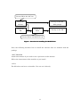
The installation procedure is described below (Figure 1).
• ICC740
Execute autorun.exe in the icc740 folder. QuickStart Installation information in the ensuing
dialog box will show you how to install and the information on product registration for
your reference.
Follow the instructions of the installer as you install. A license ID for the ICC740 is
needed.
The available period to use the ICC740 with the QuickStart key is one month. Please be
sure to receive the “permanent key” from IAR Systems within one month after you
installed. For details on how to get and set up the permanent key, refer to QuickStart
Installation information.
• TM
The necessary version of the TM is V3.20 or later.
If you do not have V3.20 or later installed in your computer, install it.
Follow the instructions of the installer as you install.
• TW74
Make sure the ICC740 and the TM are installed before you install the TW74.
Follow the instructions of the installer as you install.
The license for the M3T-ICC740 is authenticated in this tool.
10
License ID for the ICC740
Install the
Develop at the MS-
ICC740
DOS prompt
Install the
Install the
TM
TW74
Develop in the TM
License ID for the M3T-ICC740
Figure 1 Procedure for installing the M3T-ICC740
Next, the following describes how to install the software that are included with the
package.
• M3T-PD38SIM
Install this software if you wish to run a quick tour of this manual.
Follow the instructions of the installer as you install.
• SC74
The SC74 does not have an installer. You can use it directly.
11
3. Starting and Quitting the TM
3.1.
Starting the TM
When the TM has been installed normally, you can start it from the Start menu by selecting
Programs → RENESAS-TOOLS → TM V.3.xx
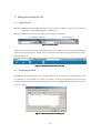
When the TM has started up, the project bar in Figure 2 appears.
Tool Register button
Close button
Figure 2 Project Bar
When started for the first time, the Project Bar is in a “floating” state. Grasp this window
and bring it to the top of the screen, and you can have it located at the uppermost part of the
desktop(Figure 3).
Figure 3 Project Bar pasted at the top
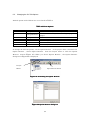
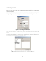
3.2.
Registering the Editor
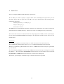
The TM does not internally have any specific editor. You can register any desired editor that
is available on the market. To register an editor, click the Tool Register button. In the
ensuing Tools Information dialog box (Figure 4), select the EDIT TOOL tab and register any
editor you want.
Figure 4 Tools Information dialog box
12
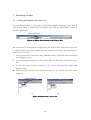
3.3.
Quitting the TM
To quit the TM, click the [Close] button in the project bar (when in a floating state) or rightclick in the project bar and select Exit from the context menu (Figure 5)
Figure 5 Context menu displayed by right-clicking
13
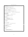
4. Quick Tour
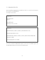
Let’s try using the TM actually following a quick tour.
In the TM, you need to specify a project name and a working directory before you can
develop a project. In the quick tour, the TM is set up as shown below. This setting can be
changed as necessary.
Working directory: c:\work\proj_1
Project name: proj_1
Source file: tutor3.c
The TM does not automatically generate a directory for each project you create. Projects are
generated in the working directory. Users must create a working directory as necessary.
The source file tutor3.c was derived from the sample program of LAR Systems by altering it
for use with the M3T-PD38SIM. Processing by this program and the source code of it are
shown below.
Processing
The program comprises an infinite loop in a while statement of the main function.
The variable my_char assumes values ‘a’ to ‘z’ at random depending on the function.
When the variable my_char assumes the value ‘i’, a BRK instruction interrupt is generated
by the function.
The function brk_interrupt is executed by a BRK instruction interrupt, setting the variable
my_char to ‘.’. The statement interrupt[0x00] of this function sets the address of the function
brk_interrupt in the BRK instruction interrupt vector for the 3803 group.
Thereafter, processing in an infinite loop of the main function is repeated.
14
Source program tutor3.c
/*----------------------------------------------------* File: tutor3.c
*
* Purpose: Handling real time interrupts
*
* Usage: ICC
-r -L -q tutor3.c
*
XLINK
-r -f <link file> tutor3
*
* Description: Using BRK vector to print a character
*
* Copyright 1997 IAR Systems
*
* $Id: tutor3.c 1.3 1998/01/15 09:24:55Z Laban Exp $
*-----------------------------------------------------*/
#pragma language=extended
#include <stdlib.h>
#include <stdio.h>
#include "intr740.h"
/* enable use of extended keywords */
/* include intrinsics */
/**********************************
*
Variables
*
**********************************/
char my_char = '*';
int call_count = 0;
/**********************************
*
Start of code
*
**********************************/
void interrupt [0x00] brk_interrupt(void)
{
// putchar('I');
my_char='.';
}
void execute_brk(void)
{
break_instruction();
}
/* Use intrinsic function */
void do_foreground_process(void)
{
call_count++;
// putchar(my_char);
my_char = rand() % 26 + 'a';
}
void main(void)
{
while (1)
{
do_foreground_process();
if (my_char=='i') execute_brk();
}
}
15
4.1.
Creating a New Project
Click the New Project button in the project bar (Figure 6).
New Project Button
Figure 6 New Project Button in the Project Bar
A new project wizard of the project editor will be launched. In this wizard, make the
necessary selection shown in Table 1.
Table 1 New Project Wizard Execution Steps
Step
Step 1
Step 2
Step Compiler
Step Finish
Selection
For the Target chip, select the 740 Family (ICC740).
Select C Project.
For the compiler package, select the TW74. When this is
selected, the ICC740 will be used when you compile. For the
Specify a startup program, select the check box titled “A default
startup program is used”.
Click the Finish Button.
A new project will be displayed in the project editor (Figure 7).
Figure 7 Project Editor
16
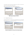
4.2.
Complementing a New Project
To develop an ICC740 project in the TM, you need to complement the new project.
Follow the procedure described below to complement your new project.
1.
In the project tree of the project editor, click the plus sign [+] for [all] to display
[.\proj_1.695].
2.
Click [+] for [.\proj_1.695] following [all] to display [.\proj_1.cmd].
3.
Click [.\proj_1.cmd] and then the Add File button (Figure 8 (a)).
4.
In the ensuing Open dialog box, select “All Files” for File Types and add the lnk740.xcl
file present in the working directory (Figure 8 (b)).
5.
When you add the lnk740.xcl file, the screen changes to the one shown in Figure 8 (c),
with lnk740.xcl added to the project.
Add File Button
(a) Before registration
(b) Open dialog box
(c) After registration
Figure 8 Complementing a new project
17
4.3.
Creating a File
Create a source file using the editor. Because tutor3.c is located in the SmpTw74 folder, copy
it to the working directory. The SmpTw74 folder is created in the folder in which you
installed the TW74 (normally \MTOOL).
4.4.
Registering the File
The source file you created need to be registered to the project. Since the source file cannot
be registered by simply placing it in the working directory, follow the procedure described
below to register it.
1.
In the project editor, click on the [.\proj_1.695] file to select it and then click the Add File
button (Figure 9 (a)).
2.
In the ensuing Open dialog box, select “Source Files” for File Types and add the source
file.
3.
A source file whose extension changed to “.r31” will be registered below
[.\proj_1.695 ](Figure 9 (b)).
4.
Click [+] for the source file whose extension changed to “.r31,” and the source file will be
displayed (Figure 9 (c)).
18
Add File Button
(a) Before adding a source file
(b) After adding a source file
(c) Displaying a source file
Figure 9 Registering a source file
4.5.
Saving the Project
The projected you created must be saved. Click the Save button of the project editor (Figure
10).
Save Button
Figure 10 Save button of the Project Editor
19
4.6.
Building a Project
To build a project, use the Build, the Rebuild or the Partial Build Button in the Project
Bar. Here, click the Rebuild Button (Figure 11).
The builder will be launched, allowing you to build a project (Figure 12).
If you’ve finished building without causing any error, a proj_1.695 file will be generated
in the working directory.
Build, Rebuild and Partial Build buttons
Figure 11 Build, Rebuild and Partial Build buttons in the Project Bar
Figure 12 Builder
20
4.7.
Starting the Debugger
For the project you’ve finished building, an absolute file proj_1.695 is generated in the
working directory.
This file proj_1.695 can be debugged by the M3T-PD38 or M3T-PD38SIM. Click the Start
Debug Button in the Project Bar (Figure 13).
Debug button
Figure 13 Start Debugger button in the Project Bar
In the initial state, since there are no debuggers registered in your system, the Tools
Information dialog box is displayed (Figure 14).
If the M3T-PD38SIM or M3T-PD38 was installed in your computer before you installed the
TW74, the installed debuggers are displayed in the dialog box. So select the check box for the
debugger you want to use (flagged by a check mark when selected).
Figure 14 DEBUG TOOL tab of the Tools Information dialog box
21
If the M3T-PD38SIM and M3T-PD38 are not displayed in the dialog box, use the Add...
button to register the debuggers. After registering the debuggers, select the check box for
the debugger you want to use (Figure 15).
Add button
(a) Initial state
(b) After registering debuggers
Figure 15 Registering debuggers
22
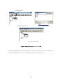
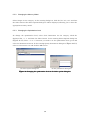
4.8.
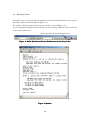
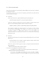
Debugging a Program
Use the M3T-PD38SIM to debug the program (Figure 16).
File menu
Window menu
Go button
Global window
SRC button
View button
Program window
Figure 16 M3T-PD38SIM
If this is the first time you start the M3T-PD38SIM, you must set up the SFR file
corresponding to the target MCU. Use the [Refer...] button at the top of the Init dialog box
(Figure 17) to set up. Select the M38000.sfr file present in the folder in which you installed
the M3T-PD38SIM.
Figure 17 Init dialog box of the M3T-PD38SIM
23
4.8.1. Loading a Program
To load a program, use the File menu commands “Download” and “Load Module.” In the
ensuing Download dialog box, select the proj_1.695 file.
A program will be loaded, with part of the program at the position of the program counter
displayed. The position of the program counter is marked by a yellow line.
4.8.2. Executing up to the main Function
First, run the program up to the main function.
To display the main function, select the View and the Source button and then select tutor3.c
and main. Then click the OK button and select the SRC button.
You will notice that dashes “-” are shown in the BRK column of the Program Window. They
indicate the positions at which you can set a breakpoint. Try double-clicking the dash “-” in
the line 00056 of the Line column. The dash “-” will change to the letter “B,” indicating that
a breakpoint has been set there.
While in this state, click the Go button. The program will be executed up to this position,
with the line 00056 turned into yellow.
4.8.3. Confirming Interrupt Generation
We’ll now confirm interrupt generation.
The brk_interrupt function is not called from any function. It can only be called by executing
the BRK instruction.
Execution of the BRK instruction is handled by the break_instruction function in the
execute_brk function. This break_instruction function is an inline function that is replaced by
the BRK instruction. The execute_brk function is called when the variable my_char is set to
‘i.’
The value of the variable my_char may be watched in the global window of the debugger.
From the BasicWindow menu, choose C Watch Window and then Global Window.
Set a breakpoint in the line 00037 of the Line column and click the Go button several times.
Then, when the variable my_char is set to ‘i,’ the line 00037 will have its color changed to
yellow. This allows you to confirm that an interrupt has been generated.
To quit the debugger, choose Exit from the File menu of the M3T-PD38SIM.
24
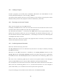
5. Creating a New Project
The ICC740 requires setting up a processor group, memory model and stack area before you
can develop a project. The M3T-ICC740 uses default settings in Table 2 as it creates a new
project.
In this manual, the project is named “proj_1.”
Table 2 Processor Group, Memory Model and Stack Area
Select items
Processor group
Memory model
Stack area
Choices
•with MUL/DIV
(without extended memory access)
•without MUL/DIV
•with extended memory access
(with MUL/DIV included)
•Tiny model
•Large model
• Zero page (000H–0FFH)
• Page 1 (100H–1FFH)
Initial settings of
M3T-ICC740
•with MUL/DIV
(without extended
memory access)
•Large model
• Page 1 (100H–1FFH)
If initial settings and choices of the M3T-ICC740 differ from those shown above, the files
and options listed in Table 3 must be altered.
Table 3 Files and Options to Alter
Select item
Processor group
Memory model
Stack area
Where to alter (chapter numbers)
Library (6.2.6)
ICC740 options (6.3.1)
A740 options (6.4.1)
Library (6.2.6)
ICC740 options (6.3.1)
A740 options (6.4.1)
cstartup.s31 file (6.1.1)
lnk740.xcl file (6.2.1)
The cstartup.s31 and lnk740.xcl files have been edited for the M38037M8 (3803 group with
1-Kbyte RAM and 32-Kbyte ROM). Therefore, reedit these files to them suitable for your
target microcomputer as necessary. Note that the *.tmk, *.tmi and *.cmd files generated in
the working directory are managed by the TM, and cannot be rewritten by users.
25
5.1.
New Project
To create a new project, you must first start the TM.
Launch the TM from the Start menu.
When the TM has started up, the project bar shown in Figure 18 appears.
New Project button
Project Editor Start button
Figure 18 Project Bar
The TM does not automatically generate a directory for each project you create. Projects are
generated in the working directory. Users must create a working directory as necessary.
There are following three methods to create a new project:
1.
Use the New Project button in the Project Bar
2.
Use the New Project button of the Project Editor (Figure 19)
3.
Select New Project from the File menu of the Project Editor
The project editor is invoked by clicking the Open Project Editor button in the project bar
(Figure 18). Whichever method you may use, a new project wizard of the project editor is
launched. So follow the execution steps of the wizard as you create a new project (see Table
4).
File menu
New Project button
Figure 19 Project Editor
26
Table 4 New Project Wizard Execution Steps
Step
Step 1
Step 2
Step Compiler
Step Finish
Selection
For the target chip, select the “740 Family(ICC740)”. If the
M3T-SRA74 is installed in your computer, you will see the “740
Family” also displayed for the target chip, but be sure to select
the “740 Family(ICC740)”.
Select a C Project.
For the compiler package, select the “TW74”. When this is
selected, the ICC740 will be used when you compile. For the
startup program, select the check box titled “A default startup
program is used”
Click the Finish button.
At this point in time, the files in Table 5 are generated in the working directory.
Table 5 New Files Created in the Working Directory
proj_1.tmk
proj_1.tmi
startup.s31
lnk740.xcl
5.2.
Project file (makefile format)
Project file (development member and document information)
Startup program
Link command file for XLINK
Complementing the Project
If the new project you are creating is an ICC740 project, you must complement it before you
can proceed.
The lnk740.xcl file copied to the working directory when creating a new project is the
command file for the linker XLINK. A method on how to locate segments and related other
information are written in it. This file is not registered to the project yet. Therefore, register
it following the procedure described below.
1. In the project tree of the project editor, click the plus sign [+] for all to
display .\proj_1.695.
2. Click [+] for .\proj_1.695 following all to display .\proj_1.cmd.
3. Click .\proj_1.cmd and then the Add File button (Figure 20 (a)).
4. In the ensuing Open dialog box, select “All files” for File Types and add the lnk740.xcl file
present in the working directory (Figure 20 (b)).
5. When you add the lnk740.xcl file, the screen changes to the one shown in Figure 20 (c),
with lnk740.xcl registered to the project.
27
Add File Button
(a) Before registration
(b) Open dialog box
(c) After registration
Figure 20 Registering the lnk740.xcl file
The .\proj_1.cmd file is not needed when you create a new project. It is created when you
build or rebuild. Because this file is managed by the TM, do not rewrite it.
28
6. Editing the Project
After you created a new project, you must edit cstartup.s31 and lnk740.xcl and change
options as necessary.
6.1.
Editing cstartup.s31
In cstartup.s31, edit the items listed in Table 6 as necessary.
Table 6 Items to Edit in cstartup.s31
Edit item
Stack page
Interrupt vector area
Subject
Stack area
Target microcomputer
Corresponding line
Line 137
Line 375
6.1.1. Changing the Stack Page
The line 137 in cstartup.s31 is used to set the stack page. Here, the stack page for the 3803
group CPU mode register is set to page 1.
LDM
#0CH, 3BH
; set stack page : 3803 Group
Set the stack page to suit your target microcomputer.
If you set the stack page to page 0, you need to change CSTACK segment settings in the
lnk740.xcl file.
6.1.2.
Changing the Interrupt Vector Area
The line 375 is used to set the size of the interrupt vector area. Here, the size of the
interrupt vector area in the 3803 group of microcomputers is set.
BLKB
0FFFEH - 0FFDCH - 2
; 3803 Group
Area settings by BLKB requires that an amount equal to the vector size be subtracted by the
set area (as subtracted by 2 in the above setting).
Note, however, that the beginning address of the interrupt vector area is set in the lnk740.xcl
file.
29
6.2.
Editing the lnk740.xcl File
You need to edit the lnk740.xcl file according to the target microcomputer, memory model
and other settings you made.
Table 7 Items to Edit in lnk740.xcl
Edit item
Subject
Stack area
Beginning address of
page 0
Ending address of page
N
ROM area address
Interrupt vector
Library
Memory model, target microcomputer
Corresponding line in
lnk740.xcl
60
Target microcomputer
38
Target microcomputer
65
Target microcomputer
Target microcomputer
Processor group
77
91
110
6.2.1. Changing the Stack Area
For the stack area to be used in the 740 family, select page 0 (00h–FFh) or page 1 (100h–
1FFh).
The ICC740 uses this stack area as CSTACK segment.
With standard settings of the M3T-ICC740, the addresses 100h–13Fh in page 1 are used for
the stack area.
-Z(NAPGE)CSTACK+40=100
The following shows a few examples of how to change.
Example 1: To use the addresses 120h–14Fh in page 1 for the stack area, alter the file as
shown below.
-Z(NAPGE)CSTACK+30=120
Example 2: To change the stack area to page 0, alter the file as shown below.
-Z(ZPAGE)CSTACK+40
Page 0 contains the segments that must be located in the SFR area and in page 0.
The
above
statement
directs
that
40h
bytes
of
INT_EXPR_STACK segment written in the line 54 be used.
30
area
following
the
Note, however, that if you change the stack area to page 0, you also need to alter the
cstartup.s31 file.
6.2.2. Changing the Beginning Address of Page 0
The ICC740 requires that the RAM area be set separately for page 0 and page N (from the
address 100h on). To set page 0, specify -Z(ZPAGE).
-Z(ZPAGE)ZPAGE,C_ARGZ,Z_UDATA,Z_IDATA=41-FF
The above setting directs that the ZPAGE, C_ARGZ, Z_UDATA and Z_IDATA segments be
located in a RAM space from the address 41h to the address FFh following the SFR area
(0h–40h). Because these segments are intended for use by the ICC740, do not delete them.
An example of how to change is shown below.
Example: For the microcomputers whose SFR area is not set beginning with the address 0h
as in the case of the 7220 series, change the settings of page 0 as follows:
-Z(ZPAGE)ZPAGE,C_ARGZ,Z_UDATA,Z_IDATA=0-BF
the case of the 7220 series, change the settings of page 0 as follows:
6.2.3. Changing the Ending Address of Page N
To set page N, specify -Z(NPAGE).
For the ending address of page N, set the ending address of the RAM of the target
microcomputer.
-Z(NPAGE)NPAGE,C_ARGN,N_UDATA,N_IDATA,ECSTR=100-43F
The above setting directs that the NPAGE, C_ARGN, N_UDATA, N_IDATA and ECSTR
segments be located in a RAM space from the address 100h to the address 43Fh. Because
these segments are intended for use by the ICC740, do not delete them.
If the CSTACK segment is located in one page, the NPAGE segment is located beginning
with the address following the CSTACK segment (with standard settings, the address 140h).
For the ending address of page N, set the last address of the RAM area in the target
microcomputer. This setting will allow you to inspect overflow in the RAM area.
For the microcomputers whose SFR area exists also in page N as in the case of the 38C2
31
group, remove the SFR area from page N.
6.2.4. Changing the ROM Area Address
Set the ROM area as suitable for your target microcomputer. Here, you set a general
program area and a special page.
Set a general program area, as shown below.
-Z(CODE)RCODE,Z_CDATA,N_CDATA,C_ICALL,C_RECFN,CSTR,
CCSTR,CODE,CONST=C080-FEFF
The above setting directs that segments for the ROM area be located in a ROM space
ranging from the beginning address C080h of the ROM area to the address FEFFh
preceding the special page.
For the microcomputers that have a reserved ROM area, however, the ROM segment space
must be set to begin from an address following that reserved area. Also make sure the ROM
segment space is set to end at an address preceding the special page or the interrupt vector
area.
The special page area must be set to end at an address preceding the interrupt vector area.
The C_FNT segment indicates the special page area.
This setting will allow you to check to see if the ROM segments are located overlapping the
interrupt vector area.
-Z(CODE)C_FNT=FF00-FFDB
6.2.5. Changing the Interrupt Vector Area
Change the interrupt vector area.
In the ICC740, the INTVEC segment indicates the interrupt vector area.
-Z(CODE)INTVEC=FFDC-FFFD
The above shows how to set the interrupt vector area in the 3803 group of microcomputers.
Make this setting as suitable for your target microcomputer.
32
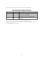
6.2.6. Changing the Library
Select the library that suits the processor group and memory model of your target
microcomputer from Table 8.
Table 8 Processor Group, Memory Model and Library
with MUL/DIV
without MUL/DIV
with extended memory access
Tiny model
cl7400t.r31
cl7401t.r31
cl7402t.r31
Large model
cl7400l.r31
cl7401l.r31
cl7402l.r31
There is a “-C” statement at the place where you specify a library. Do not delete it.
33
6.3.
Changing the ICC740 Options
Default options of the ICC740 are set as listed in Table 9.
Table 9 ICC740 Options
Option
-z9
Category
Code generation
-e
Code generation
-K
-r
-ml
-v0
-o
Code generation
Debug
Target
Target
Command line
Description
Specifies code size prioritized optimization.
Enables extended specification (e.g., zpage and
npage).
Enables C++ comment (“//”).
Outputs debugging information.
Selects Large model for the memory model.
Selects an MCU with MUL/DIV.
Sets an object file name.
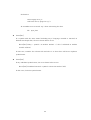
To change the ICC740 options, use the Option Browser
Option Browser , choose Option Browser
Browser
of the project editor. To launch the
from the Project menu or click the Option
button (Figure 21). When you choose Option Browser , the Option Browser
dialog box in Figure 22 is displayed.
Project
Menu
Option Browser button
Figure 21 Launching the Option Browser
Figure 22 Option Browser dialog box
34
In this dialog box, click the option macro CFLAGS and then the Edit button. The Options
dialog box for the ICC740 will appear (Figure 23 (a)).
Before setting each option here, select a category first (Figure 23 (b)).
For details about the options, refer to the manual included with the ICC740.
(a) When opened
(b) Selecting a category
Figure 23 Options dialog box for the ICC740
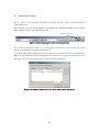
6.3.1. Changing the Processor Group
In the Options dialog box, select Target for the category (Figure 24). In the ensuing dialog
box, click the list “-v0, -v1, -v2” and then the Select button. The Select Options dialog box
will be displayed, allowing you to select a processor group.
Figure 24 Selecting Target for the category and the Select Options dialog box
35
6.3.2. Changing the Memory Model
Select Target for the category. In the ensuing dialog box, click the list “-ml, -mt” and then
the Select button. The Select Options dialog box will be displayed, allowing you to select the
appropriate memory model.
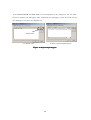
6.3.3. Changing the Optimization Level
To change the optimization level, select Code Generation for the category. Click the
displayed list “-z, -s” and then the Select button. In the ensuing Select Options dialog box
(Figure 25 (a)), select “-z” or “-s.” Because you need to set the optimization level, go on and
select the Parameters button. In the ensuing Specify Parameters dialog box (Figure 25 (b)),
select a value from 0 to 9 and click the OK button.
(a) Select option dialog box
(b) Set parameter dialog box
Figure 25 Changing the optimization level in the Select option dialog box
36
6.4.
Changing the A740 Options
Default options of the A740 are set as listed in Table 10.
Table 10 Default Options of the A740
Option
-uN
-v0
-o
Category
Code generation
Target
Command line
Description
Sets 16-bit addressing.
Selects a MCU with MUL/DIV.
Sets an object file name.
To change the A740 options, use the Option Browser dialog box as for the ICC740 options.
Click the option macro AFLAGS and then the Edit button. The Options dialog box for the
A740 will be displayed (Figure 26).
Figure 26 Options dialog box for the A740
6.4.1. Changing the Processor Group
Select Target for the category. In the ensuing dialog box, click the list “-v0, -v1, -v2” and then
the Select button. The Select Options dialog box will be displayed, allowing you to select a
processor group.
37
6.4.2. Changing the Memory Model
Select Code Generation for the category. If all of the referenced symbols are located in page 0,
deselect the “-uN” option from the list in the displayed dialog box. Although the “-uN” option
can be left intact without causing any adverse effects on program behavior, deselecting it
will help to reduce the ROM size and increase the processing speed.
Note, however, that if the “-uN” option is deselected while the referenced symbols are
located in other than page 0, an error may occur in XLINK. For the countermeasures to be
taken in that case, refer to Section 8.2.
38
6.5.
Changing the XLINK Options
The XLINK options are set in the lnk740.xcl file and in the TM.
Default options of XLINK in the TM are set as listed in Table 11.
Table 11 Default Options of XLINK (Command Line)
Option
-o
-Fieee695
Category
Output file
Output file
-ylmba
Output file
-l
-x
-f
List control
List control
Include
Description
Sets an object file name.
Specifies a format. To allow the file to be debugged in the
M3T-PD38 or M3T-PD38SIM, specify ieee695 that
indicates the IEEE-695 format.
Additional information of IEEE-695. For the M3T-PD38
and M3T-PD38SIM, specify “lmba”.
Outputs a map file.
Outputs a cross reference list to the map file.
Specifies a command file. This is automatically set by the
TM.
To change the XLINK options, use the Option Browser dialog box as for the ICC740 options.
Click the option macro LFLAGS and then the Edit button. The Options dialog box for the
XLINK will be displayed.
There are no XLINK options that are associated with the editing of a project.
39
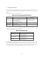
7. Developing a Project
7.1.
Creating and Registering the Source Files
Use your desired editor to create the C source and assembly language source files. If
your desired editor is registered in the project bar, click the Open Editor button to
invoke it (Figure 27).
Editor Start button
Figure 27 Editor Start button in the Project Bar
The source files you created must be registered to the project. These files are not registered
by simply placing them in the working directory. Follow the procedure described below to
register the source files.
1.
In the project editor, click on the .\proj_1.695 file to select it and then click the Add File
button (Figure 28 (a)).
2.
In the ensuing Open dialog box, select “Source Files” for File Types and add the source
file.
3.
A source file whose extension changed to “.r31” will be registered below .\proj_1.695
(Figure 28 (b)).
4.
Click [+] for the source file whose extension changed to “.r31,” and the source file will be
displayed.
Add File button
(a)
(b)
Figure 28 Registering a source file
40
7.2.
Altering the lnk740.xcl File
If you’ve created new segments in an assembler source file, etc., you must set the locations of
those segments in the lnk740.xcl file.
An example is shown below.
< sample.s31 >
...
RSEG RAM_DATA
BLKB 10
...
RSEG ROM_DATA
BYTE ‘Please enter your name’
...
< lnk740.xcl >
...
-Z(NPAGE)NPAGE,C_ARGN,N_UDATA,N_IDATA,ECSTR=100-43F
-Z(NPAGE) RAM_DATA=100-43F
...
-Z(CODE)RCODE,Z_CDATA,N_CDATA,C_ICALL,C_RECFN,CSTR,CCSTR,CODE,
CONST=C080-FEFF
-Z(CODE) ROM_DATA= C080-FEFF
...
In the above example, the RAM_DATA segment is located after the ECSTR segment, and
the ROM_DATA segment is located after the CONST segment.
41
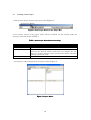
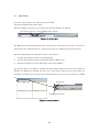
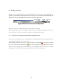
8. Building a Project
When you’ve finished creating and registering the source files, execute Build to
generate an absolute module from the source files. To execute Build, click the Build, the
Rebuild or the Partial Build button in the project bar (Figure 29).
Partial Build
Build Rebuild
Figure 29 Build buttons located in the Project Bar
When you click one of the Build buttons, the builder is launched.
The builder builds a project according to the button you’ve clicked, and displays the result.
If an error occurs, correct the project according to the displayed message.
8.1.
Errors in the C Compiler ICC740 and the Assembler A740
If an error occurs while you are executing the C compiler ICC740 or the assembler A740,
correct the file in which the error occurred.
In the builder, when an error occurs, the relevant line is marked by
occurs, the relevant line is marked by
, and when a warning
. If the editor registered in the TM has a function to
open the file by specifying its line number, you can display the spot in error by doubleclicking on the marked line. This helps you identify the spot in error easily.
42
8.2.
Errors in the Linker XLINK
If an error occurs while you are executing the linker XLINK, correct the project according to
the displayed messages.
The following describes the errors that are frequently encountered in the linker and the
corrective actions to be taken.
z
Error[e16]
If data cannot all fit into a segment, XLINK outputs the following error.
Error[e16]: Segment Segment is too long for segment definition.
In this case, change the segment size or move the segment to another location. Note,
however, that the following segments cannot be moved out of page 0.
ZPAGE, Z_UDATA, Z_IDATA, C_ARGZ, EXPR_STACK, INT_EXPR_STACK
The Z_UDATA, Z_IDATA and C_ARGZ segments are the segments in which variables
are located. By attaching npage to any variable, you can move that variable to the
N_UDATA, N_IDATA or C_ARGZ segment. However, do not forget npage in the
external declaration of the function that references the variable and in the prototype
declaration as well.
z
Error[e18]
If the data located in page N is accessed in zero-page addressing mode, the error shown
below occurs.
Error[e18]: Range error in ( module ), segment segment at address address. Value
value, in tag tag, is out of bounds (0x0-0xff)
In this case, relocate the data in page N to page 0 or change the method by which the
data is referenced.
Method of relocating the data in page N to page 0:
In C sources, attach zpage when defining the location.
In assembler sources, make sure the relevant symbol will be located in page 0
Method of reference when located in page N:
In C sources, attach npage when defining the function externally. If npage is
specified in the argument to the function, npage is also required for the prototype
43
declaration.
extern npage int n_i1;
void func( char a, npage int n_b );
In assembler sources attach “np.” when referencing the data.
lda np:n_data
z
Error[e27]
If a symbol with the same name (including any C language variable or function) is
defined in multiple files, the error shown below occurs.
Error[e27]: Entry " symbol " in module module 1 ( file 1) redefined in module
module 2 (file 2)
In this case, examine the relevant file and alter it so that there will be no duplicate
symbol name.
z
Error[e46]
If any undefined symbol exists, the error shown below occurs.
Error[e46]: Undefined external " symbol " referred in module ( file )
In this case, check the symbol name.
44
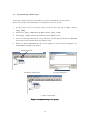
8.3.
Setting Options in Source File Units
In C and assembler source files, it may sometimes be necessary to set options in file units.
In such a case, create additional option macros in file units.
These option macros can be created in the same way for both C and assembler source files.
Therefore, explanation is given by using a C source file as an example below.
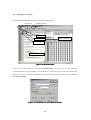
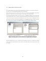
In the Option Browser dialog box, click “icc740” or “CFLAGS” (Figure 30 (a)). The New
button will become active, so click it. The Options dialog box will be displayed. Because the
values of the respective options in this dialog box are the same as those of CFLAGS, change
the values as necessary and click the OK button. A CFLAGS option macro will be created.
As you repeat this operation, the number of option macros increases (Figure 30 (b)).
(a) Before setting option macros
(b) After adding option macros
Figure 30 Setting options in source file units in the Option Browser dialog box
The new option macros you’ve created are not assigned to any file yet. Click on an option
macro and in the Selected Files section, click on a file name. The selected option macro will
be enabled.
45
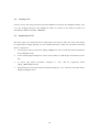
9. Debugging a Project
For the project you’ve finished building, an absolute file proj_1.695 is generated in the
working directory.
This file can be debugged in the M3T-PD38 or M3T-PD38SIM. In the TM, you can use
the Debug button in the project bar to invoke the debugger (Figure 31).
Debug Button
Figure 31 Debug button in the Project Bar
The debugger invoked this way is the one that you registered to the TM.
If there are no registered debuggers, the Tool Information dialog box will be displayed. So
register a debugger on the DEBUG TOOL tab of this dialog box (Figure 32).
Add button
(a) With no debugger list
(b) With a debugger list
Figure 32 DEBUG TOOL tab of the Tool Information dialog box
In the TM, furthermore, if the M3T-PD38 or M3T-PD38SIM was already installed before
you installed the TW74, the installed debuggers are automatically listed (Figure 32 (b)). If
you installed the M3T-PD38 or M3T-PD38SIM after installing the TW74, no debuggers are
listed. In this case, the installed debuggers are automatically listed when you reinstall the
TW74.
To register one of the listed debuggers, select its check box (marked by a check mark when
selected).
Other debug tools are not automatically listed. Therefore, use the Add button to register any
debug tool you want.
46
If you installed the M3T-PD38 or M3T-PD38SIM after installing the TW74, you must
register the installed debugger in the same way as you do for other debug tools. In this case,
the registered debugger will have “user” appended in the Name column as for other debug
tools. The difference is whether or not the .695 file for the project is automatically loaded
when you invoked the debug tool using the Launch Debugger button.
For the debuggers marked by “user” in the Name column, the file is not automatically loaded.
Therefore, you need to load the .695 file for the project from the File menu of the M3T-PD38
or M3T-PD38SIM.
If you want the file to be automatically loaded by the M3T-PD38 or M3T-PD38SIM by
clicking the Launch Debugger button, reinstall the TW74.
47
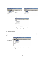
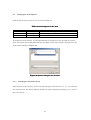
10. Creating a Hex File
Before you can create a Hex file, you must first register xlink(lmc) as a load module
converter to the TM.
First, choose Information from the Project menu of the project editor. The Project Properties
dialog box (Figure 33) will be displayed. Select the Tools tab of this dialog box.
Figure 33 Project Properties dialog box
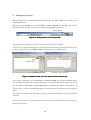
Next, select the “xlink(lmc)” check box in the package information section and click the OK
button.
You will see that xlink(lmc) is registered in the Option Browser dialog box (Figure 34), so
that xlink(lmc) will henceforth be executed after xlink.
Figure 34 Option Browser dialog box with xlink(lmc) registered
48
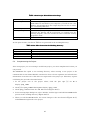
Note that the options of xlink(lmc) in the TM are set as listed in Table 12.
Table 12 Default Options of xlink(lmc) (Command Line)
Option
-o
-Fintel-standard
Category
Output file
Output file
-Y0
Output file
-f
Include
Description
Sets an object file name.
Specifies a format. For the Intel Hex files to be
output, specify “intel-standard”.
Additional information of intel-standard. For use in
the mask file conversion utility MM, specify “0”.
Specifies a command file. This is automatically set
by the TM.
When you execute Build, the builder creates two files, IEEE695 and Hex.
xlink(lmc) converts the formats of the files generated by xlink from IEEE695 to Hex. It uses
the same lnk740.xcl file as does xlink.
49
M3T-ICC740 V.1.00 User’s Manual
Rev. 1.00
July 16, 2004
REJ10J0750-0100Z
COPYRIGHT ©2004 RENESAS TECHNOLOGY CORPORATION
AND RENESAS SOLUTIONS CORPORATION ALL RIGHTS RESERVED
M3T-ICC740 V.1.00
User’s Manual
1753, Shimonumabe, Nakahara-ku, Kawasaki-shi, Kanagawa 211-8668 Japan
REJ10J0750-0100Z