1
Siemens BACnet Heat
Pump Controller – MultiStage Owner’s Manual
125-699
Rev. BA, July 2009
Siemens Building Technologies, Inc.
i
Rev. BA, July 2009
NOTICE
The information contained within this document is subject to change without notice and should not be construed as a
commitment by Siemens Building Technologies, Inc. Siemens Building Technologies, Inc. assumes no responsibility
for any errors that may appear in this document.
All software described in this document is furnished under a license and may be used or copied only in accordance
with the terms of such license.
WARNING
This equipment generates, uses, and can radiate radio frequency energy and if not installed and used in accordance
with the instructions manual, may cause interference to radio communications. It has been tested and found to
comply with the limits for a Class A digital device, pursuant to Part 15 of the FCC rules. These limits are designed to
provide reasonable protection against such interference when operated in a commercial environment. Operation of
this equipment in a residential area is likely to cause interference in which case users at their own expense will be
required to take whatever measures may be required to correct the interference.
SERVICE STATEMENT
Control devices are combined to make a system. Each control device is mechanical in nature and all mechanical
components must be regularly serviced to optimize their operation. All Siemens Building Technologies branch offices
and authorized distributors offer Technical Support Programs that will ensure your continuous, trouble-free system
performance.
For further information, contact your nearest Siemens Building Technologies, Inc. representative.
Copyright 2009 by Siemens Building Technologies, Inc.
TO THE READER
Your feedback is important to us. If you have comments about this document, please contact your local Siemens
Building Technologies representative.
CREDITS
Product or company names mentioned herein may be the trademarks of their respective owners
Pirnted in the U.S.A.
Table of Contents
How to Use This Manual...............................................................................................III
Manual Organization ..................................................................................................III
Manual Conventions ..................................................................................................III
Manual Symbols ........................................................................................................IV
Getting Help ...............................................................................................................IV
Product Overview .........................................................................................................1
Introduction ...................................................................................................................1
Ordering Notes...........................................................................................................1
Hardware Inputs ........................................................................................................2
Analog .....................................................................................................................2
Digital ......................................................................................................................2
Hardware Outputs ......................................................................................................2
Analog .....................................................................................................................2
Digital ......................................................................................................................3
Power Wiring ...........................................................................................................3
Communication Wiring ............................................................................................3
Controller LED Indicators...........................................................................................4
Temperature Sensors ................................................................................................4
Room Temperature Sensor.....................................................................................4
Mixed Air Temperature Sensor ...............................................................................4
Actuators ....................................................................................................................4
Related Equipment ..................................................................................................5
Applications...................................................................................................................7
Basic Operation.............................................................................................................7
Control Temperature Setpoints..................................................................................7
Day/Night Mode .........................................................................................................7
Night Mode Override Switch ......................................................................................7
Control Loops.............................................................................................................7
Mixed Air Control Loop ............................................................................................7
Calibration ..................................................................................................................8
Heating and Cooling Switchover ...............................................................................9
Electric Reheat...........................................................................................................9
Siemens Building Technologies, Inc.
I
Siemens BACnet Heat Pump Controller - Multi-Stage Owner’s Manual
Compressor Operation ..............................................................................................9
Fan Operation ............................................................................................................9
Power Failure Recovery ............................................................................................10
Centralized Alarm Monitoring ....................................................................................10
Overriding DOs ..........................................................................................................10
Fail-safe Operation ....................................................................................................10
Using Auxiliary Points ................................................................................................11
Application 2583: Multiple Compressor Heat Pump with Reversing Valve Control and
Mixed Air Control ..........................................................................................................12
Compressor Staging ..................................................................................................12
Reversing Valve Operation ........................................................................................12
Application Notes .......................................................................................................12
Application 2584: Multiple Heating and Cooling Heat Pump with Mixed Air and Internal
Reversing Valve Control...............................................................................................14
Compressor/Electric Heat Staging ............................................................................14
Application Notes .......................................................................................................14
Application 2590: BACnet Heat Pump Slave Mode ...................................................16
Using the Controller as a Point Extension Device .....................................................16
Point Database ..............................................................................................................18
Overview ........................................................................................................................18
Troubleshooting ............................................................................................................28
Basic Service Information ..........................................................................................28
Preventive Maintenance ............................................................................................28
Safety Features..........................................................................................................29
Controller LEDs..........................................................................................................29
Glossary .........................................................................................................................30
Overview ....................................................................................................................30
Index ...............................................................................................................................34
II
Siemens Building Technologies, Inc.
How to Use This Manual
This manual is written for the owner and user of the Siemens Building Technologies, Inc.
Heat Pump Controller—Multi-Stage, often referred to as controller for the remainder of this
manual. This manual is designed to help you become familiar with the controller and its
applications.
This chapter covers manual organization, manual symbols and conventions used in the
manual, and how to access help.
Manual Organization
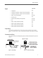
This manual contains the following chapters:
•
Chapter 1 Product Overview, describes the hardware components and accessories
used with the controller.
•
Chapter 2 Applications, describes the control applications available in the controller.
•
Chapter 3 Point Database, defines the point database descriptors and includes
addresses and applications.
•
Chapter 4 Troubleshooting, describes basic corrective measures to take should you
encounter a problem when using this controller. For issues not covered in this
chapter, contact your local Siemens Building Technologies representative.
•
A Glossary describes the terms and acronyms used in this manual.
•
An Index is provided to assist you in finding information.
Manual Conventions
The following table lists conventions used in this manual.
Convention
Actions that you should
perform are specified in
boldface font.
Example
Type F for Field panels.
Click OK to save changes and close the dialog box.
Error and system
messages are displayed
in Courier New font.
The message Report Definition successfully renamed
appears in the status bar.
New terms appearing for
the first time are
italicized.
The Open Processor continuously executes a user-defined set of
instructions called the control program.
Siemens Building Technologies, Inc.
III
Siemens BACnet Heat Pump Controller - Multi-Stage Owner’s Manual
Manual Symbols
The following table lists symbols that are used to draw your attention to important
information.
Notation
Symbol
Meaning
CAUTION:
Indicates that equipment damage or loss of data may occur
if the user does not follow a procedure as specified.
WARNING:
Indicates that personal injury or loss of life may occur to the
user if a procedure is not performed as specified.
Getting Help
For more information about the Siemens BACnet Heat Pump Controller—Multi-Stage,
contact your local Siemens Building Technologies representative.
IV
Siemens Building Technologies, Inc.
1
Product Overview
Introduction
The Siemens BACnet Heat Pump Controller—Multi-Stage is used in multiple compressor
heat pump applications. lt provides Direct Digital Control (DDC) for two heat pump
applications. The controller can operate as an independent, stand-alone DDC room controller
or it can be networked with a field panel.
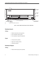
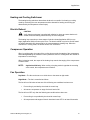
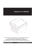
The controller provides all termination, input/output, system, and local communication
connections (Figure 1). The controller hardware consists of the controller with cover and
mounting bracket.
Table 1. Siemens BACnet Heat Pump Controller – Multi-Stage Applications.
Application
Number
Application Description
2583
Multiple Compressor with Reversing Valve and Mixed Air Control
2584
Multiple Heating and Cooling with Internal Reversing Valve
and Mixed Air Control
2590
Slave Mode
Ordering Notes
Siemens BACnet Heat Pump Controller – Multi-Stage
Siemens Building Technologies, Inc.
550-490
1
Siemens BACnet Heat Pump Controller - Multi-Stage Owner’s Manual
COVER
CONTROLLER
BOARD
MOUNTING
HOLE
(2)
24 V-AC
RX TX BST
C H GND
FLN TRUNK
+ -
+ -
DO 1 DO 2 DO 3 DO 4 DO 5 DO 6 DO 7 DO 8
NO C NO C NO C NO C NO C NO C NO C NO C
1 2 3 4 5 6 7 8 9 10 11 12 13 14 15 16
AI 3 AI 4 AI 5
+ - + - + -
DI 2
DI 6
AO 1 AO 2 AO 3
+ - + - + -
1 2 3 4 5 6 7 8 9 10 11 12 13 14 15 16
RTS
MOUNTING
RAIL
1 2 3 4 5 6 7 8 9 10 11 12 13 14 15 16 1 2 3 4 1 2 1 2 3 4 5 6 7 8 9 10
DO LEDS
TEC04XXR1
POWER
TRUNK
TERMINATIONS
FLN TRUNK
TERMINATIONS
INPUT / OUTPUT TERMINATIONS
ROOM TEMPERATURE
SENSOR / HMI PORT
RECEIVE LED, TRANSMIT LED, AND BST LED
Figure 1. Siemens BACnet Heat Pump ControlIer—Multi-Stage.
Hardware Inputs
Analog
•
Mixed air temperature sensor (optional)
•
Room Temperature Sensor (RTS)
•
Room temperature setpoint dial (optional)
•
Heat pump alarm (optional)
•
Night mode override (optional)
•
Wall switch (optional)
Digital
Hardware Outputs
Analog
•
2
Damper actuator (spring return) (optional)
Siemens Building Technologies, Inc.
Product Overview
Application
Digital
•
Compressor 1
2583
•
Compressor 2 (optional); or stage 3 electric heat (optional)
2583
•
Compressor 3 (optional); or stage 2 electric heat (optional)
2583
•
Stage 1 electric heat (optional)
2583, 2584
•
Reversing valve
2583
•
Damper actuator (floating control) (optional)
2583, 2584
•
Fan
2583, 2584
•
Stage 1 cooling compressor (optional)
2584
•
Stage 2 cooling compressor (optional)
2584
•
Stage 1 heating compressor (optional)
2584
•
Stage 2 heating compressor (optional)
2584
Power Wiring
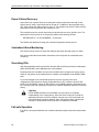
The controller is powered by 24 Vac. Power wiring connects to terminals on the controller
labeled “C” (Common) and “H” (Hot). An earth ground termination is also present. See Figure
3.
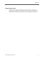
Communication Wiring
The controller connects to the field panel by means of a Field Level Network (FLN) trunk. See
Figure 4.
3-WIRE FLN TRUNK
POWER TRUNK
24 V COMMON
24 V HOT
E GRND
Figure 3. Power Wiring.
Siemens Building Technologies, Inc.
REFERENCE (EQUIPOTENTIAL)
GROUNDED AT SINGLE LOCATION
TYPICALLY AT FIELD PANEL
REFERENCE CONNECTION ABSENT
IF 2-WIRE CABLE MUST BE USED
TWISTED PAIR
TEC0528R1
TEC0471R2
C H EGRND WHEN THIRD TERMINATION IS PRESENT
REFERENCE
IS NOT SHIELD
SHIELD
WIRENUT
Figure 4. Communication Wiring.
3
Siemens BACnet Heat Pump Controller - Multi-Stage Owner’s Manual
Controller LED Indicators
The controller has several Light Emitting Diode (LED) indicators. (Figure 1). Table 2 lists the
LED types and what they indicate.
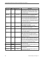
Table 2. Controller LEDs.
LED Type
Label
(if present)*
Indication
DO
LED 1–LED 8
Receive
RX
Indicates , when flashing, that the controller is receiving
information from the field panel.
Transmit
TX
Indicates, when flashing, that the controller is transmitting
information to the field panel.
Basic Sanity
Test
BST
Indicates the ON/OFF status of the DO associated with it. A
glowing LED indicates that the DO is energized.
Indicates, when flashing ON and OFF once per second, that
the controller is functioning properly.
* Some LED labels may be hidden by the controller cover.
Temperature Sensors
An electronic Room Temperature Sensor (RTS) or an optional auxiliary temperature sensor
may be used with the Siemens BACnet Heat Pump Controller—Multi-Stage.
Room Temperature Sensor
The controller room temperature sensor connects to the controller by means of a cable
preterminated at both ends with a 6-conductor RJ-11 plug-in connector. See Figure 1 for the
location of the RTS/Human-Machine lnterface (HMl) port.
Mixed Air Temperature Sensor
The mixed air temperature sensor is a 10K Ω thermistor that connects to the controller at Al
5.
For more information about Siemens temperature sensors, contact your local Siemens
Building Technologies representative.
Actuators
The actuator used with the Siemens BACnet Heat Pump Controller—Multi-Stage may be an
optional floating control or 0 to 10V spring return electronic damper motor that is powered
through the controller to position an outside air damper.
For more information about Siemens actuators, contact your local Siemens Building
Technologies representative.
4
Siemens Building Technologies, Inc.
Product Overview
Related Equipment
•
Relay Module
•
Damper Actuator(s)
•
Mixed Air Temperature Sensor (optional)
•
Room Temperature Sensor
Contact your local Siemens Building Technologies, Inc. representative for product numbers
and more information.
Siemens Building Technologies, Inc.
5
Siemens BACnet Heat Pump Controller - Multi-Stage Owner’s Manual
6
Siemens Building Technologies, Inc.
2
Applications
Basic Operation
The Siemens BACnet Heat Pump Controller—Multi-Stage provides Direct Digital Control
(DDC) technology for multiple compressor heat pump applications. Temperature control
varies with the application. If present, mixed air temperature control and up to three stages of
electric heat or staged heating and cooling can be provided.
Control Temperature Setpoints
The controller maintains a specified temperature setpoint based on Day/Night mode, the
heating/cooling mode, and the setpoint dial (if used).
Day/Night Mode
The controller maintains the specified day setpoint temperature during daytime hours and the
specified night setpoint at night.
Night Mode Override Switch
If the RTS has an override switch, it can be used to command the controller into day mode
for an adjustable period of time. This only affects a controller in night mode.
Control Loops
Heating Loop – maintains room temperature setpoint by turning compressors and electric
heat stages on and off.
Cooling Loop – maintains room temperature setpoint by turning compressors on and off and
using free cooling (mixed air control) when available.
Mixed Air Control Loop
The heat pump is controlled by three Proportional, Integral, and Derivative (PID) control
loops; a cooling loop and a heating loop. This section describes the mixed air control loop.
Siemens Building Technologies, Inc.
7
Siemens BACnet Heat Pump Controller - Multi-Stage Owner’s Manual
The mixed air loop controls only the mixed air portion of the application.
The mixed air damper motor can be either a spring return or floating control damper motor.
•
For a spring return damper, the mixed air loop will control the damper through its 0 to
10 volt analog output and the digital outputs will be spare.
•
For a floating control damper the mixed air loop will control the damper through DO 1
and DO 2, and the analog output will be a spare.
CAUTION:
This application does not have built in low temperature detection for the mixed
air dampers. The low temperature detection is handled differently depending on
what type of damper is used (spring return or floating control).
Stand-alone low temperature detection is not possible with floating control
dampers. A program can be written in the field panel to close the damper when a
low temperature situation occurs. Contact your local Siemens Building
Technologies representative for more information.
Day Mode – When heating is required and the fan is on, the damper is set to minimum
position. If the fan is off, the damper is closed.
When cooling is required the damper will be modulated by the mixed air temperature control
loop. Damper position will not be set below minimum position to make sure that the
ventilation requirements are being met.
Night Mode – The damper is closed (0%) during night mode when cooling is not required
and/or mixed air control is not used at night.
Mixed Air Control - When cooling is required the damper will be modulated by the mixed air
temperature control loop.
If the cooling loop is between the limits for free cooling and all other conditions have been
met for enabling the mixed air loop, control depends on the following:
•
If the cooling loop was previously higher than free cooling, the mixed air loop will
remain enabled.
•
If the cooling loop was previously lower than free cooling, the mixed air loop will
remain disabled.
NOTE:
This can happen in day or night mode.
Calibration
Floating Control Damper – The damper is briefly commanded closed to get an accurate
damper position during calibration.
8
Siemens Building Technologies, Inc.
Applications
Heating and Cooling Switchover
The heating/cooling switchover determines whether the controller is in heating or cooling
mode by monitoring the room temperature and the demand for heating and cooling (as
determined by the temperature control loops).
Electric Reheat
CAUTION:
Verify that the equipment is supplied with safeties by others to ensure that there is
airflow across the heating coils when they are to be energized.
The heating loop controls up to three stages of electric reheat (Application 2583) or one
stage (Application 2584) to warm up the room. The electric reheat is cycled on and off based
on heating demand that is determined by the room temperature heating loop. When the
controller is in cooling mode, the electric heat is OFF at all times.
Compressor Operation
When in cooling mode, the output of the cooling loop controls the staging of the compressors
and enabling/disabling the mixed air control (used as a source of cooling when the outside air
temperature is cool enough.
When in heating mode, the output of the heating loop controls the staging of the compressors
or electric heat.
Application 2583 only. When cooling or heating mode is opposite the reversing
valve control, the compressors are turned off.
NOTE:
Fan Operation
Day Mode – The fan can be set to run all the time or the same as night mode.
Night Mode – The fan is controlled as follows:
The fan will turn ON when at least one of the following two conditions has been met:
•
Free cooling is provided by the mixed air control loop.
•
At least one compressor or stage of electric heat is ON.
The fan will turn OFF only after the following two conditions have been met:
•
Free cooling is not provided by the mixed air control loop.
•
All compressors and stages of electric heat have been OFF for at least 30 seconds.
Siemens Building Technologies, Inc.
9
Siemens BACnet Heat Pump Controller - Multi-Stage Owner’s Manual
Power Failure Recovery
Upon return from a power failure, the heating and cooling compressors are kept off, the
electric heat (if used) is kept off and the fan is kept off. In addition to the equipment being
OFF, both cooling and heating loops are set to 0. This situation will remain in effect until the
power failure recovery period for this controller is over.
The controller returns to normal control when its power failure recovery period is over. The
power failure recovery time for a heat pump is based on the following formula:
RETURN DELAY + (CTLR ADDRESS × 10 seconds)
This lessens the demand of having all the electrical equipment starting at once.
Centralized Alarm Monitoring
DI 6 can be used to monitor an input that changes state when the heat pump is in alarm.
DI 6 can be unbundled to send alarm information to the field panel for centralized alarm
monitoring.
Overriding DOs
Heat Pump applications allow spare DOs, damper (DO1 and DO2) and electric heat stages
(DO3, DO6 and DO7 when applicable) to be commanded.
Physical points DO1 and DO2 can never be overridden when configured for motor control.
However, the position of the attached motor is always commandable via the DMPR COMD
point.
To prevent damage to the mechanical equipment, the fan, reversing valve, and
compressor(s) DOs cannot be directly commanded ON or OFF unless the point HP DO
OVRD is set to ENABLE. When HP DO OVRD is set to DISABL (default), commands to the
fan, reversing valve and compressor DO points are ignored regardless of BACnet command
priority.
CAUTION:
HP DO OVRD should be set to ENABLE only when there is a complete
understanding of the consequences. Since the direct control will override the
application minimum on/off time safeties, improper use of DO commands can
cause permanent equipment damage. Also, during normal daily operation the
override of critical DOs should only be done via a BACnet command.
Fail-safe Operation
If the RTS or the setpoint dial fails, the controller operates using the last known temperature
value.
10
Siemens Building Technologies, Inc.
Applications
Using Auxiliary Points
lt is possible to have extra points available on a Heat Pump Controller—Multi-Stage in
addition to the ones used by the current application that is running in the controller. If these
extra points will be controlled by a field panel, they must be unbundled at the field panel.
Siemens Building Technologies, Inc.
11
Siemens BACnet Heat Pump Controller - Multi-Stage Owner’s Manual
Application 2583: Multiple Compressor Heat Pump
with Reversing Valve Control and Mixed Air Control
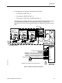
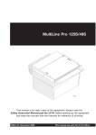
In Application 2583 (Figure 5), the controller controls a multi-stage heat pump with a
reversing valve controlled by the heat pump controller. In addition to compressors, this heat
pump may also be equipped with electric heat for auxiliary heat and mixed air control for free
cooling. The mixed air control can use either a spring return or a floating control damper
motor.
Compressor Staging
Three compressors or electric heat stages are available for use. Each compressor has a time
delay (at least 30 seconds) to lessen the demand of having more than one compressor stage
start at once.
Reversing Valve Operation
The reversing valve determines the operation of the heat pump's compressors (heating or
cooling) depending on the demand.
Application Notes
1. If the heat pump cycles excessively, temperature swings in the room are excessive, or
there is trouble maintaining the setpoint, the cooling loop, the heating loop, or both need
to be tuned. Contact your local Siemens Building Technologies representative for more
information.
2. The Heat Pump Controller—Multi-Stage, as shipped from the factory, keeps all
associated equipment OFF. The controller and its equipment are released to application
control at start-up.
3. Running the mixed air loop during night mode can increase energy savings by taking
advantage of free cooling at night to pre-cool the building for day mode, and, thereby,
reduce the need for mechanical cooling during day mode. This method for pre-cooling
the building can also improve indoor air quality because it is accomplished with fresh air.
A field panel program can be written to pre-cool the building with this application. Contact
your local Siemens Building Technologies representative for more information.
12
Siemens Building Technologies, Inc.
Applications
4. In this application, the maximum configurations are as follows:
•
The maximum of CMP TOTL = 3.
•
The maximum of EHTG STG CNT = 3.
•
The maximum of CMP TOTL plus EHTG STG CNT = 4.
If these limits are exceeded, CMP TOTL will be set to 0 and EHTG STG CNT will be set
to 0. These points will remain at 0 until they are set correctly. This prevents the
application from trying to use the same DO as both a compressor and a stage of electric
heat.
SUPPLY AIR
COMPRESSOR 1
COMPRESSOR 2
REVERSING
VALVE
ELECTRIC
HEAT
(OPTIONAL)
COMPRESSOR 3
REVERSING
VALVE
REVERSING
VALVE
HEATING /
COOLING
O.A.
N.C.
COIL
COIL
COIL
O.A.
DAMPER*
(OPTIONAL)
FAN
N.O.
WATER
SOURCE
COIL
MIXED AIR
TEMPERATURE
SENSOR
(OPTIONAL)
COIL
COIL
R.A.
R.A.
DAMPER*
(OPTIONAL)
* THE O.A. AND R.A. DAMPERS MUST
BE MECHANICALLY LINKED.
24 V-AC
FLN TRUNK
AO1 (0-10V) *
DO1
DO2
DO3
DO4
DO5
DO6
DO7
DO8
DI3/AI3
DI4/AI4
DI5/AI5
DI2
DI6
AO2 (0-10V)
AO3 (0-10V)
RTS
1ST STAGE ELECTRIC HEAT (OPTIONAL)
REVERSING VALVE
COMPRESSOR 1
COMPRESSOR 2; OR 3RD STAGE ELECTRIC HEAT (OPTIONAL)
COMPRESSOR 3; OR 2ND STAGE ELECTRIC HEAT (OPTIONAL)
FAN
SPARE AI (0-10V or 4-20mA) OR SPARE DI (DRY CONTACT)
SPARE AI (10K THERMISTOR) OR SPARE DI (DRY CONTACT)
MIXED AIR TEMPERATURE SENSOR 10K THERMISTOR (OPTIONAL)
TEC2573CDR1
N.O.
HEAT PUMP ALARM (OPTIONAL)
WALL
SWITCH
(OPTIONAL)
RTS
* ON BOARD, AO1 IS GROUPED PYSICALLY WITH AO2 AND AO3
HEAT PUMP
CONTROLLER MULTI-STAGE
Figure 5. Application 2583 Control Drawing.
Siemens Building Technologies, Inc.
13
Siemens BACnet Heat Pump Controller - Multi-Stage Owner’s Manual
Application 2584: Multiple Heating and Cooling
Heat Pump with Mixed Air and Internal Reversing
Valve Control
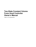
ln Application 2584, (Figure 6) the controller controls one or two heating compressors for
heating and one or two cooling compressors for cooling. The reversing valve is controlled
internally by the heat pump. ln addition to compressors, this heat pump may also be
equipped with electric heat for auxiliary heat and mixed air control for free cooling. This
application also controls small air handling units with two position heating and cooling control.
The mixed air control can use either a spring return or a floating control damper motor.
Compressor/Electric Heat Staging
This application can support up to two cooling compressors and up to two heating
compressors. Each compressor heat has a time delay (at least 30 seconds) to lessen the
demand of having more than one compressor start at once.
Application Notes
1. lf the heat pump cycles excessively, temperature swings in the room are excessive, or
there is trouble maintaining the setpoint, the cooling loop, the heating loop or both need
to be tuned. Contact your local Siemens Building Technologies representative for more
information.
2. The Heat Pump Controller—Multi-Stage, as shipped from the factory, keeps all
associated equipment OFF. The controller and its equipment are released to application
control at start-up.
3. Running the mixed air loop during night mode can increase energy savings by taking
advantage of free cooling at night to pre-cool the building for day mode, and thereby,
reduce the need for mechanical cooling during day mode. This method for pre-cooling
the building can also improve indoor air quality because it is accomplished with fresh air.
A field panel program can be written to pre-cool the building with this application. Contact
your local Siemens Building Technologies representative for more information.
4. ln this application the maximum configurations are as follows:
•
The maximum of HTG CMP TOTL (Point 75) = 2.
•
The maximum of CLG CMP TOTL (Point 77) = 2.
•
The maximum of EHTG STG CNT (Point 76) = 1.
lf these limits are exceeded, HTG CMP TOTL, CLG CMP TOTL, and EHTG STG CNT will all
be set to 0. These points will remain at 0 until they are set correctly. This prevents the
application from trying to control equipment that it does not have.
14
Siemens Building Technologies, Inc.
Applications
SUPPLY AIR
COMPRESSOR 2
COMPRESSOR 1
REVERSING
VALVE*
REVERSING
VALVE*
ELECTRIC
HEAT
(OPTIONAL)
HEATING /
COOLING
O.A.
N.C.
COIL
COIL
O.A.
DAMPER**
(OPTIONAL)
FAN
N.O.
WATER
SOURCE
MIXED AIR
TEMPERATURE
SENSOR
(OPTIONAL)
COIL
COIL
R.A.
R.A.
DAMPER**
(OPTIONAL)
* CONTROLLED INTERNALLY BY THE HEAT PUMP
** THE O.A. AND R.A. DAMPERS MUST
BE MECHANICALLY LINKED.
24 V-AC
FLN TRUNK
AO1 (0-10V) *
DO1
DO2
DO3
DO4
DO5
DO6
DO7
DO8
DI3/AI3
DI4/AI4
DI5/AI5
DI2
DI6
AO2 (0-10V)
AO3 (0-10V)
RTS
ELECTRIC HEAT (OPTIONAL)
1ST HEATING COMPRESSOR
2ND HEATING COMPRESSOR
1ST COOLING COMPRESSOR
2ND COOLING COMPRESSOR
FAN
SPARE AI (0-10V or 4-20mA) OR SPARE DI (DRY CONTACT)
SPARE AI (10K THERMISTOR) OR SPARE DI (DRY CONTACT)
MIXED AIR TEMPERATURE SENSOR 10K THERMISTOR (OPTIONAL)
TEC2574CDR1
N.O.
HEAT PUMP ALARM (OPTIONAL)
WALL
SWITCH
(OPTIONAL)
RTS
* ON BOARD, AO1 IS GROUPED PYSICALLY WITH AO2 AND AO3
HEAT PUMP
CONTROLLER MULTI-STAGE
Figure 6. AppIication 2584 Control Drawing.
Siemens Building Technologies, Inc.
15
Siemens BACnet Heat Pump Controller - Multi-Stage Owner’s Manual
Application 2590: BACnet Heat Pump Slave Mode
Application 2590 is the default slave mode application that comes up when power is first
applied to the controller. Slave mode provides no control. lts purpose is to allow the operator
to perform equipment checkout before a control application is put into effect and to set some
basic controller parameters (CTLR ADDRESS, APPLlCATlON, etc.).
Using the Controller as a Point Extension Device
lf the controller is used only as a point extension device with no control application in effect,
the application must be set to slave mode and the points must be unbundled at the field
panel. All of these points must be controlled from the field panel in order to be used.
16
Siemens Building Technologies, Inc.
Applications
Siemens Building Technologies, Inc.
17
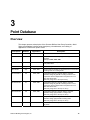
3
Point Database
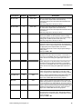
Overview
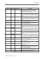
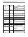
This chapter presents a description of the Siemens BACnet Heat Pump Controller—MultiStage point database including point descriptors, point addresses, and a listing of
applications in which each point is found.
Description
Address
Application
CTLR ADDRESS
01
2583, 2584, 2590
ldentifies the controller on the FLN trunk.
APPLICATION
02
2583, 2584, 2590
Identification number of the program running in the
controller.
Valid input: 2583, 2584, 2590
RETURN DELAY
03
2583, 2584
ROOM TEMP
{04}
2583, 2584, 2590
HEAT.COOL
{05}
2583, 2584
Current mode of operation for applications that can be either
a heating mode or a cooling mode.
DAY CLG STPT
06
2583, 2584
Temperature setpoint in degrees that the controller
maintains during day periods in cooling mode if a room
temperature sensor setpoint dial is not present or is not
used. See STPT DIAL.
Valid entry range: 48° to 95°F (9°to 35°C)
DAY HTG STPT
07
2583, 2584
Temperature setpoint in degrees that the controller
maintains during day periods in heating mode if a room
temperature sensor setpoint dial is not present or is not
used. See STPT DIAL.
Valid entry range: 48° to 95°F (9° to 35°C)
NGT CLG STPT
08
2583, 2584
Temperature setpoint in degrees that the controller
maintains during night periods in cooling mode.
Valid entry range: 48° to 95°F (9° to 35°C)
NGT HTG STPT
09
2583, 2584
Temperature setpoint in degrees that the controller
maintains during night periods in heating mode.
Valid entry range: 48° to 95°F (9° to 35°C)
DMPR MlN POS
10
2583, 2584
Minimum position the damper will be commanded to during
day mode.
Siemens Building Technologies, Inc.
Description
Amount of time the heat pump will remain off after a return
from power failure.
Actual reading from the room temperature sensor.
18
Point Database
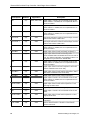
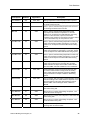
Description
Address
Application
Description
RM STPT MlN
11
2583, 2584
Minimum temperature setpoint in degrees that the controller
can use from the setpoint dial. This overrides any
temperature setpoint from the setpoint dial that falls below
this minimum.
Valid entry range: 48° to 95°F (9° to 35°C)
RM STPT MAX
12
2583, 2584
Maximum temperature setpoint in degrees that the controller
can use from the setpoint dial. This overrides any
temperature setpoint from the setpoint dial that raises above
this maximum.
Valid entry range: 48° to 95°F (9° to 35°C)
RM STPT DIAL
{13}
2583, 2584, 2590
Temperature setpoint in degrees from the room temperature
sensor (not available on all temperature sensor models).
This setpoint will be used for control in day mode (heating or
cooling) when enabled by STPT DIAL (Point 14).
Valid entry range: 48° to 95°F (9° to 35°C)
STPT DIAL
14
2583, 2584
YES indicates that there is a room setpoint dial on the room
temperature sensor and must be used as the temperature
setpoint for control in day/occupied mode. NO indicates that
the appropriate preset setpoint will be used as the
temperature setpoint for control in day/occupied heating or
cooling mode.
Valid input: YES or NO
AUX TEMP
{15}
2590
Actual reading from a 10K Ω thermistor connected to the
controller's AI 5 input. When a thermistor is connected at
Al 5, DI 5 is not available. See DI 5. The physical input can
not be used for both analog and digital input at the same
time.
MA TEMP
{15}
2583, 2584
Actual reading from a 10K Ω thermistor connected to the
controller's Al 5 input. When a thermistor is connected at
Al 5, DI 5 is not available. See DI 5. The physical input can
not be used for both analog and digital input at the same
time.
CMP2 ON
16
2583
Value, in percent, that the active temperature control loop
output must exceed for compressor 2 to turn ON. Actual
turn on is subject to the CMP2 MlN OFF time being expired.
HTG CMP2 ON
16
2584
Value, in percent, that the heating control loop output must
exceed for compressor 2 to turn ON. Actual turn on is
subject to the CMP2 MlN OFF time being expired.
CMP2 OFF
17
2583
Value, in percent, that the active temperature control loop
output must go below for compressor 2 to turn OFF. Actual
turn off is subject to the CMP2 MlN ON time being expired.
HTG CMP2 OFF
17
2584
Value, in percent, that the heating control loop output must
go below for compressor 2 to turn OFF. Actual turn off is
subject to the CMP2 MlN ON time being expired.
WALL SWITCH
18
2583, 2584, 2590
Siemens Building Technologies, Inc.
YES indicates that the controller is to monitor the status of a
wall switch that is connected to Dl 2. NO indicates that the
controller will not monitor the status of a wall switch, even if
one is connected.
Valid input: YES or NO
19
Siemens BACnet Heat Pump Controller - Multi-Stage Owner’s Manual
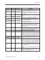
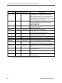
Description
Address
Application
Description
Dl OVRD SW
{19}
2583, 2584, 2590
Actual indication of the status of the override switch (not
physically available on all temperature sensor models) at the
room temperature sensor. ON indicates that the switch is
being pressed. OFF indicates that the switch is released.
Valid input: ON or OFF
OVRD TIME
20
2583, 2584
Amount of time in hours that the controller will operate in
day/occupied mode when the override switch is pressed
while the controller is in night/ unoccupied mode.
NGT OVRD
{21}
2583, 2584
Indicates the mode that the controller is operating in with
respect to the override switch. NIGHT indicates that the
switch has not been pressed and the override timer is not
active. DAY indicates that the switch has been pressed and
the override timer is active. The controller then uses a day
mode temperature setpoint. This point is only in effect when
DAY.NGT indicates night mode.
22
All
FREE CLG
{23}
2583, 2584
DI 2
{24}
2583, 2584, 2590
Actual status of a contact connected to the controller at Dl 2.
ON indicates that the contact is closed; OFF indicates that
the contact is open. If a wall switch is used, it is connected
to DI 2. See WALL SWITCH.
DI 5
{25}
2583, 2584, 2590
Actual status of a contact connected to the controller at
Al 5/Dl 5. ON indicates that the contact is closed; OFF
indicates that the contact is open. When a contact is
connected at Dl 5, Al 5 is not available. See Point number
15. The physical input can not be used for both analog and
digital input at the same time.
DI 6
{26}
2583, 2584, 2590
Actual status of a contact connected to the controller. ON
indicates that the contact is closed; OFF indicates that the
contact is open. Application 2583/2584: DI 6 can be used to
monitor an input that changes state when the heat pump is
in alarm. DI 6 can be unbundled to send alarm information
to the field panel for centralized alarm monitoring.
CMP2 MlN OFF
27
2583
Minimum time, in minutes, that compressor 2 will remain
OFF before turning ON.
HTG2 MlN OFF
27
2584
Minimum time, in minutes, that heating compressor 2 will
remain OFF before turning ON.
CMP2 MlN ON
28
2583
Minimum time, in minutes, that compressor 2 will remain ON
before turning OFF.
HTG2 MlN ON
28
2584
Minimum time, in minutes, that heating compressor 2 will
remain ON before turning OFF.
RMTMP OFFSET
20
Compensates for deviations between the value of ROOM
TEMP and the actual room temperature. This corrected
value is displayed in CTL TEMP.
RMTMP OFFSET + ROOM TEMP = CTL TEMP
Point commanded by the field panel PPCL to enable or
disable mixed air control (free cooling).
Siemens Building Technologies, Inc.
Point Database
Description
Address
Application
{29}
2583, 2584, 2590
CLG CMP1 ON
30
2584
Value, in percent, that the cooling temperature control loop
output must exceed for cooling compressor 1 to turn ON.
Actual turn on is subject to the CLG1 MlN OFF time being
expired.
CLG CMP1 OFF
31
2584
Value, in percent, that the cooling temperature control loop
output must go below for cooling compressor 1 to turn OFF.
Actual turn off is subject to the CLG1 MlN ON time being
expired.
CLG1 MlN OFF
32
2584
Minimum time, in minutes, that cooling compressor 1 will
remain OFF before turning ON.
CLG1 MlN ON
33
2584
Minimum time, in minutes, that cooling compressor 1 will
remain ON before turning OFF.
CLG CMP2 ON
34
2584
Value, in percent, that the cooling temperature control loop
output must exceed for cooling compressor 2 to turn ON.
Actual turn on is subject to the CLG 2 MIN OFF time being
expired.
CMP3 ON
34
2583
Value, in percent, that the active temperature control loop
output must exceed for compressor 3 to turn ON. Actual
turn on is subject to the CMP3 MlN OFF time being expired.
CLG CMP2 OFF
35
2584
Value, in percent, that the cooling temperature control loop
output must exceed for cooling compressor 2 to turn OFF.
Actual turn off is subject to the CLG2 MIN ON time being
expired.
CMP3 OFF
35
2583
Value, in percent, that the active temperature control loop
output must go below for compressor 3 to turn OFF. Actual
turn off is subject to the CMP3 MlN ON time being expired.
CLG2 MIN OFF
36
2584
Minimum time, in minutes, that cooling compressor 2 will
remain OFF before turning ON.
CMP3 MlN OFF
36
2583
Minimum time, in minutes, that compressor 3 will remain
OFF before turning ON.
CLG2 MlN ON
37
2584
Minimum time, in minutes, that cooling compressor 2 will
remain ON before turning OFF.
CMP3 MlN ON
37
2583
Minimum time, in minutes, that compressor 3 will remain ON
before turning OFF.
DAMPER TYPE
38
2583, 2584
FLOAT indicates that a floating control damper is used.
SPRING indicates that a spring return damper is used.
Valid input: FLOAT or SPRING.
AO DIR.REV
39
2583, 2584
Configuration setup code for AO. Allows the AO to be direct
(normally closed) or reverse acting (normally open).
{40}
2583, 2584, 2590
DAY.NGT
AOV1
Siemens Building Technologies, Inc.
Description
Indicates the mode in which the controller is operating.
Day temperature setpoints are used in day mode.
Night temperature setpoints are used in night mode. This
point is normally set by the field panel.
Analog output 1 controls a 0 to 10V signal.
21
Siemens BACnet Heat Pump Controller - Multi-Stage Owner’s Manual
Description
Address
Application
DO 1
{41}
2583, 2584, 2590
Digital output 1 controls a 24 Vac load with an ON or OFF
status. If Motor 1 is enabled, DO 1 is coupled with DO 2 to
control an actuator.
DO 2
{42}
2583, 2584, 2590
Digital output 2 controls a 24 Vac load with an ON or OFF
status. lf Motor 1 is enabled, DO 2 is coupled with DO 1 to
control an actuator.
DO 3
{43}
2590
Digital output 3 controls a 24 Vac load with an ON or OFF
status. lf Motor 2 is enabled, DO 3 is coupled with DO 4 to
control an actuator.
ELEC HEAT
{43}
2584
This output controls the contact for the first stage of electric
heat and has a status of ON or OFF.
ELEC HEAT 1
{43}
2583
This output controls the contact for the first stage of electric
heat and has a status of ON or OFF.
DO 4
{44}
2590
Digital output 4 controls a 24 Vac load with an ON or OFF
status. lf Motor 2 is enabled, DO 4 is coupled with DO 3 to
control an actuator.
HTG CMP 1
{44}
2584
Digital output used to control the heating compressor 1.
REV VALVE
{44}
2583
Digital output used to control the reversing valve.
COOL and HEAT status is indicated for the 24 Vac valve or
relay. The default configuration is energized for HEAT. The
configuration may be reversed in DO DIR.REV.
DO 5
{45}
2590
Digital output 5 controls a 24 Vac load with an ON or OFF
status. lf Motor 3 is enabled, DO 5 is coupled with DO 6 to
control an actuator.
COMPRESSOR 1
{45}
2583
Digital output used to control the compressor. ON or OFF
status is indicated for the 24 Vac relay.
HTG CMP 2
{45}
2584
Digital output used to control heating compressor 2. ON or
OFF status is indicated for the 24 Vac relay.
CLG CMP 1
{46}
2584
Digital output used to control cooling compressor 1.
DO 6
{46}
2590
Digital output 6 controls a 24 Vac load with an ON or OFF
status. lf Motor 3 is enabled, DO 6 is coupled with DO 5 to
control an actuator.
EHEAT3.CMP2
{46}
2583
Digital output used to control either compressor 2 or the
third stage of electric heat.
CLG CMP 2
{47}
2584
Digital output used to control cooling compressor 2.
DO 7
{47}
2590
Digital output 7 controls a 24 Vac load with an ON or OFF
status.
EHEAT2.CMP3
{47}
2583
Digital output used to control either compressor 3 or 2nd
stage of electric heat.
DMPR COMD
{48}
2583, 2584
MTR1 COMD
{48}
2590
22
Description
Value to which the damper motor is commanded in percent
of full travel.
Value to which the Motor 1 actuator is commanded in
percent of full travel.
Siemens Building Technologies, Inc.
Point Database
Description
Address
Application
Description
DMPR POS
{49}
2583, 2584
Current position of the damper motor in percent of full travel.
This value is calculated based on motor run time.
MTR1 POS
{49}
2590
Current position of the damper motor in percent of full travel.
This value is calculated based on motor run time. See
MTR1 TIMING.
DO 8
{50}
2590
Digital output 8 controls a 24 Vac load with an ON or OFF
status.
FAN
{50}
2583, 2584
Digital output used to control the fan. ON indicates the DO is
energized; OFF indicates the DO is de-energized.
MTR TIMING
51
2583, 2584
Time required for the damper actuator to travel from full
closed to the full open position.
MTR1 TIMING
51
2590
Time required for the Motor 1 actuator to travel from full
closed to the full open position.
AI 3
{52}
2583, 2584, 2590
Spare analog input, switch selectable to be 0-10V or 420mA (consult your Siemens Building Technologies
representative). Or, spare DI dry contact, see DI 3. The
physical input can not be used for both analog and digital
input at the same time.
AI 4
{53}
2583, 2584, 2590
Spare anolog input, 10K Ω thermistor. Or, spare DI dry
contact, see DI 4. The physical input can not be used for
both analog and digital input at the same time.
AOV 2
{54}
2583, 2584, 2590
Analog output 2 controls a 0 to 10V signal.
DI 3
{55}
2583, 2584, 2590
Actual status of a contact connected to the controller at
Dl 3. ON indicates that the contact is closed; OFF indicates
that the contact is open. When a contact is connected at Dl
3, Al 3 is not available. See AI 3. The physical input can not
be used for both analog and digital input at the same time.
DMPR ROT ANG
56
2583, 2584
Number of degrees the damper is free to travel.
DPR1 ROT ANG
56
2590
Number of degrees the damper is free to travel.
{57}
2583, 2584, 2590
Actual status of a contact connected to the controller at
Dl 4. ON indicates that the contact is closed; OFF indicates
that the contact is open. When a contact is connected at Dl
4, Al 4 is not available. See AI 4. The physical input can not
be used for both analog and digital input at the same time.
58
2583, 2584, 2590
Configuration setup code for Motors 1 and 2. This enables
the motors individually and sets each motor to be either
direct or reverse acting.
DI 4
MTR SETUP
NOTE: When a motor is enabled, its associated DOs are
enabled.
DO DIR.REV
59
2583, 2584, 2590
Siemens Building Technologies, Inc.
Configuration setup code for DOs. Allows the DOs to be
direct or reverse acting (enabled equals energized or
disabled equals de-energized).
23
Siemens BACnet Heat Pump Controller - Multi-Stage Owner’s Manual
Description
CYCLE FAN
Address
Application
Description
60
2583, 2584
YES indicates that the fan should cycle ON and OFF with
the compressor during day mode. NO indicates that the fan
should remain ON constantly in day mode.
Valid input: YES or NO
NOTE: In either case, the fan will cycle during night mode.
FREE CLG ON
61
2583, 2584
Value, in percent, that the cooling loopout must exceed for
free cooling to turn ON.
FREE CLG OFF
62
2583, 2584
Value, in percent, that the cooling loopout must exceed for
free cooling to turn OFF.
CLG P GAIN
63
2583, 2584
Proportional gain value for the cooling temperature control
loop.
CLG I GAIN
64
2583, 2584
Integral gain value for the cooling temperature control loop.
STPT SPAN
65
2583, 2584
Used to configure the allowable temperature range when
using the optional Relative Setpoint Adjustment feature.
STAT TYPE
66
2583, 2584
Default = NORMAL. Can be set to OFFSET for optional
Relative Setpoint Adjustment feature when room sensor part
number SB1-0916 or SB1-1072 is used.
Valid input: NORMAL or OFFSET
HTG P GAIN
67
2583, 2584
Proportional gain value for the heating temperature control
loop.
HTG I GAIN
68
2583, 2584
Integral gain value for the heating temperature control loop.
HP DO OVRD
69
2583, 2584
For the commanding of critical digital outputs. CAUTION:
IMPROPER USE CAN CAUSE PERMANENT EQUIPMENT
DAMAGE.
STPT OFFSET
{70}
2583, 2584
For use with optional Relative Setpoint Adjustment feature.
MA P GAIN
{71}
2583, 2584
Proportional gain value for the mixed air control loop.
MA I GAIN
{72}
2583, 2584
Integral gain value for the mixed air control loop.
MA D GAIN
{73}
2583, 2584
Derivative gain value for the mixed air control loop.
MA BIAS
{74}
2583, 2584
Biasing of the mixed air control loop.
CMP TOTL
75
2583
Number of compressors used by the application.
Valid values: 0, 1, 2, 3
HTG CMP TOTL
75
2584
Number of heating compressors used by the application.
Valid values: 0, 1, 2
EHTG STG CNT
76
2583, 2584
CLG CMP TOTL
77
2584
CTL TEMP
{78}
2583, 2584, 2590
Temperature used as input for the temperature
control loops. This value will be the same as the value in
ROOM TEMP + RMTMP OFFSET unless it is overridden.
CLG LOOPOUT
{79}
2583, 2584
Cooling temperature control loop output value in percent.
24
Number of electric heating stages used by the application.
Valid values: 0, 1, 2, 3
Number of cooling compressors used by the application.
Valid values: 0, 1, 2
Siemens Building Technologies, Inc.
Point Database
Description
Address
Application
HTG LOOPOUT
{80}
2583, 2584
ELEC HEAT ON
81
2584
Value, in percent, that the heating Ioopout must exceed for
the electric heat to turn ON.
EHEAT 1 ON
81
2583
Value, in percent, that the heating loopout must exceed for
the first stage of electric heat to turn ON.
CMP1 ON
82
2583
Value, in percent, that the active temperature control
loop output must exceed for compressor 1 to turn ON.
Actual turn on is subject to the CMP MlN OFF time being
expired. lt is also the value, in percent, which HTG
LOOPOUT must go below for the electric heat (ELEC HEAT
1) to turn OFF when only one compressor is used.
HTG CMP1 ON
82
2584
Value, in percent, that the heating temperature control loop
output must exceed for heating compressor 1 to turn ON.
Actual turn on is subject to the HTG1 MlN OFF time being
expired.
CMP1 OFF
83
2583
Value, in percent, that the active temperature control loop
output must go below for compressor 1 to turn OFF. Actual
turn off is subject to the CMP1 MlN ON time being expired.
HTG CMP1 OFF
83
2584
Value, in percent, that the heating temperature control loop
output must go below for heating compressor 1 to turn OFF.
Actual turn off is subject to the HTG1 MlN ON time being
expired.
RVAL SWITCH
84
2583
Value, in percent, that the active temperature control loop
output must go above for the reversing valve to switch.
Actual switchover is subject to the status of HEAT.COOL,
RVAL SW TIME, and HTG LOOPOUT or CLG LOOPOUT.
SWITCH LIMIT
85
2583, 2584
Active temperature control loop output must be less than
this value to switch between cooling mode and heating
mode. Actual switchover depends on SWITCH DBAND
being exceeded and is subject to SWITCH TIME being
expired.
SWITCH TIME
86
2583, 2584
Time, in minutes, that must expire to switch between cooling
mode and heating mode. Actual switchover depends on the
active temperature control loop being below the value of
SWITCH LIMIT and exceeding the value of SWITCH
DBAND.
CMP1 MlN OFF
87
2583
Minimum time, in minutes, that compressor 1 will remain
OFF before turning ON.
HTG1 MlN OFF
87
2584
Minimum time, in minutes, that heating compressor 1 will
remain OFF before turning ON.
CMP1 MlN ON
88
2583
Minimum time, in minutes, that compressor 1 will remain ON
before turning OFF.
HTG1 MlN ON
88
2584
Minimum time, in minutes, that heating compressor 1 will
remain ON before turning OFF.
RVAL SW TIME
89
2583
Length of time the compressor must be OFF before the
reversing valve can switch modes.
Siemens Building Technologies, Inc.
Description
Heating temperature control loop output value in percent.
25
Siemens BACnet Heat Pump Controller - Multi-Stage Owner’s Manual
Description
Address
Application
Description
SWITCH DBAND
90
2583, 2584
Temperature range in degrees that is compared to the
difference between CTL TEMP and CTL STPT. The
difference must exceed this value for temperature control
mode to change over. Changeover is also subject to the
active temperature control loop output being below SWITCH
LIMIT and SWITCH TIME being expired.
NGT MA CTL
{91}
2583, 2584
YES indicates that mixed air control should occur during
night mode. NO indicates that mixed air control will not
occur during night mode.
Valid input: YES or NO.
CTL STPT
{92}
2583, 2584
Actual setpoint value being used as input for the active
temperature control loop.
MA STPT
{93}
2583, 2584
Setpoint of the mixed air control loop.
EHEAT 2 ON
94
2583
Value, in percent, that the heating loopout must exceed for
the second stage of electric heat to turn ON.
EHEAT 3 ON
95
2583
Value, in percent, that the heating loopout must exceed for
the third stage of electric heat to turn ON.
CAL TIMER
96
2583, 2584, 2590
Time interval, in hours, between the calibration sequence.
{97}
2583, 2584, 2590
Analog output 3 controls a 0 to 10V signal.
98
2583, 2584
ERROR STATUS
{99}
2583, 2584, 2590
CLG D GAIN
102
2583, 2584
Derivative gain value for the cooling temperature control
loop.
CLG BIAS
103
2583, 2584
Biasing of the cooling temperature control loop.
See CLG LOOPOUT.
HTG D GAIN
104
2583, 2584
Derivative gain value for the heating temperature control
loop.
HTG BIAS
105
2583, 2584
Biasing of the heating temperature control loop.
See HTG LOOPOUT.
AOV 3
LOOP TIME
26
Time, in seconds, between control loop calculations.
Status code indicating any errors detected during controller
power up. A status of 0 indicates there are no problems.
1.
Points not listed are not used in this application.
2.
Point numbers that appear in brackets { } may be unbundled at the field panel.
Siemens Building Technologies, Inc.
Point Database
Siemens Building Technologies, Inc.
27
4
Troubleshooting
This chapter describes corrective measures you can take should you encounter a problem
when using a Siemens BACnet Heat Pump Controller—Multi-Stage.
You are not required to do any controller troubleshooting. You may want to contact your local
Siemens Building Technologies representative if a problem occurs or you have any questions
about the controller.
NOTE:
When troubleshooting, record what the problem is and what actions were
performed immediately before the problem occurred. Being able to describe the
problem in detail is important, should you need assistance from your local
Siemens Building Technologies representative.
Basic Service Information
Always remove power to the controller when installing or replacing it. Since the controller
does not have a power switch, the recommended method of removing power to a locally
powered controller is to turn OFF the power to the 24 Vac transformer. The recommended
method of removing power to a controller on a power cable (even to service a single
controller) is to turn OFF the power at the transformer.
NOTE:
When removing power to a controller to perform maintenance or service, make
sure that the person in charge of the facility is aware of this and that appropriate
steps are taken to keep the building in control.
Never remove the cover from the controller. There are no serviceable parts inside. If a
problem is found with a controller, contact your local Siemens Building Technologies
representative for replacement. An anti-static wrist strap is recommended when installing or
replacing controllers.
Preventive Maintenance
Most controller components are designed so that, under normal circumstances, they do not
require preventive maintenance. Periodic inspections, voltage checks, and point checks are
normally not required. The controller's rugged design makes most preventive maintenance
unnecessary. However, devices that are exposed to dusty or dirty environments may require
periodic cleaning to function properly.
Siemens Building Technologies, Inc.
28
Troubleshooting
Safety Features
The controller board stores the controller's address, applications, and point values. In the
event of a power failure or a reset, these values are retrieved from the controller's permanent
memory and are used by the controller unless overridden by a field panel. If one of the
following conditions occurs, the controller will activate safety features present in its fail-safe
mode.
•
Sensor failure.
•
Loss of power. Upon controller power loss, communication with the controller is also
lost. The controller will appear as failed (*F*) at the field panel.
Controller LEDs
To determine if the controller is powered up and working, verify that the Basic Sanity Test
(BST) Light Emitting Diode (LED) is flashing ON/OFF once per second. The controller
contains eleven LEDs located on the circuit board. See the Controller LED lndicators section
of Chapter 1, Product Overview for more information about LEDs.
NOTE:
The TX and RX LEDs indicate communication over the FLN.
Siemens Building Technologies, Inc.
29
Glossary
Overview
The glossary contains terms and acronyms that are used in this manual. For definitions of
point database descriptors, see Chapter 3, Point Database.
Al
Analog Input. Point that receives a signal that represents a condition which has more than
two states. For example, flow rate sensors (water or air), temperature sensors (room or duct),
pressure sensors (static or velocity), and humidity sensors (room, duct, or outdoor).
airflow
Rate at which a volume of air moves through a duct. Usually expressed in cubic feet per
minute (cfm).
algorithm
Mathematical formula that uses varying inputs to calculate an output value.
AO
Analog Output. Physical point that generates a continuous variable signal.
BACnet
A data communication protocol for Building Automation and Control networks.
centralized control
Type of control offered by a controller that is connected by means of a Field Level Network
(FLN).
cfm
Cubic Feet per Minute.
Siemens Building Technologies, Inc.
30
Glossary
control loop
PID algorithm that is used to control an output based on a setpoint and an input reading from
a sensor.
DDC
Direct Digital Control.
DI
Digital Input. Physical input point that receives a two-state signal (ON/OFF, OPEN/CLOSED,
YES/NO).
DO
Digital Output. Physical output point that sends a two-state signal (ON/OFF, OPEN/CLOSED,
YES/NO).
English units
The foot-pound-second system of units for weights and measurements.
equipment controller
FLN device that provides additional point capacity to a field panel or provides individual room
or mechanical equipment control.
field panel
A device containing a microprocessor for centralized control of system components and
equipment controllers.
FLN
Field Level Network. Network consisting of equipment controllers, FLN end devices, fume
hoods, etc.
HMI
Human Machine Interface. Terminal and its interface program that allows you to
communicate with a field panel or equipment controller.
Siemens Building Technologies, Inc.
31
Siemens BACnet Heat Pump Controller - Multi-Stage Owner’s Manual
lps
Liters per Second.
loopout
The output of the control loop expressed as a percentage.
override switch
Button on a room temperature sensor that an occupant can press to change the status of a
room from unoccupied to occupied (or from night to day) for a predetermined time.
pressure independent
Variable Air Volume (VAV) room temperature control system in which the temperature drives
an airflow setpoint.
PID
Proportional, Integral, Derivative.
pressure dependent
Variable Air Volume (VAV) room temperature control system in which the temperature
directly drives the damper.
RTS
Room Temperature Sensor.
setpoint
Virtual point that stores a point value such as a temperature setting. Points that monitor
inputs, such as temperature, report actual values.
SI units
Systeme International d'Unites. The international metric system.
slave mode
Default application that displays when power is first applied to a Terminal Equipment
Controller. No control action is initiated in the slave mode.
32
Siemens Building Technologies, Inc.
Glossary
stand-alone control
Type of control offered by a controller that is providing independent DDC control to a space.
Equipment Controller
Siemens Building Technologies, Inc. product family of equipment controllers (one is the
BACnet Heat Pump Controller — Electronic Output) that house the applications software
used to control terminal units, such as heat pumps, VAV terminal boxes, fan coil units, unit
ventilators, etc.
unbundle
Term used to describe the entering of a point that resides in a controllers database into the
field panel's database so that it can be monitored and controlled from the field panel.
Siemens Building Technologies, Inc.
33
Index
A
actuator .............................................................. 4
address descriptions ........................................ 18
AI (see analog input) ........................................ 30
airflow ............................................................... 30
algorithm .......................................................... 30
analog input ........................................................ 2
analog input (Glossary) .................................... 30
analog output ...............................................2, 30
AO ........................................ (see analog output)
application
notes .......................................................12, 14
slave mode ...................................................16
Application 2583............................................... 12
compressor operation and staging ................. 9
control drawing ............................................. 13
fan operation................................................... 9
maximum configurations .............................. 13
notes ............................................................. 12
reversing valve operation ............................. 12
Application 2584............................................... 14
compressor/electric heat staging ................. 14
control drawing .......................................14, 15
maximum configurations .............................. 14
notes ............................................................. 14
Application 2590............................................... 16
applications
calibration ....................................................... 8
control loops ................................................... 7
control temperature setpoints ......................... 7
day/night mode ............................................... 7
electric reheat
stage 1 ........................................................ 9
stage 2 ........................................................ 9
stage 3 ........................................................ 9
heating and cooling switchover ...................... 9
night mode override switch............................. 7
auxiliary points, using ....................................... 11
B
Basic Sanity Test (BST) ................................... 29
basic service information ................................. 28
BST LED ......................................................4, 29
Siemens Building Technologies, Inc.
C
centralized alarm monitoring ........................... 10
centralized control ............................................ 30
communication wiring ........................................ 3
compressor
operation ........................................................ 9
control drawing
Application 2583 ........................................... 13
Application 2584 ........................................... 15
control loop ...................................................... 31
mixed air ......................................................... 7
controller
hardware ........................................................ 1
LEDs/LED indicators ................................ 4, 29
D
damper motor
floating control ................................................ 8
spring return ................................................... 8
database ............................. (see point database)
DDC (see Direct Digital Control)...................... 31
DI (see digital inputs) ....................................... 31
digital input ......................................................... 2
digital output....................................................... 3
overriding...................................................... 10
Direct Digital Control .......................................... 1
DO (see digital outputs) ................................... 31
E
English units..................................................... 31
equipment controller ........................................ 31
F
fail-safe operation ............................................ 10
fan operation ...................................................... 9
field panel................................................... 31, 33
FLN .................................................................. 31
Floor Level Network (FLN)................................. 3
H
hardware
power wiring ................................................... 3
34
Index
relay module ................................................... 5
hardware, inputs and outputs............................. 2
heat pump controller—multi-stage ..................... 1
I
inputs and outputs
analog ............................................................. 2
digital .......................................................... 2, 3
hardware......................................................... 2
L
Light Emitting Diodes (LEDs) .......................4, 29
BST ............................................................... 29
RX and TX .................................................... 29
loopout.............................................................. 32
M
mixed air control loop
day mode ........................................................ 8
night mode ...................................................... 8
MMI (see Man-Machine Interface) ................... 31
MMI port ............................................................. 4
mounting bracket................................................ 1
O
override switch ................................................. 32
overriding DOs ................................................. 10
P
PID ................................................................... 32
point database.................................................. 18
point addresses ............................................ 18
point descriptors ........................................... 18
point extension device
using controller as ........................................ 16
power failure recovery ...................................... 10
power wiring ....................................................... 3
pressure dependent ......................................... 32
preventive maintenance ................................... 28
Siemens Building Technologies, Inc.
R
related equipment .............................................. 5
relay module ...................................................... 5
reversing valve operation................................. 12
Room Temperature Sensor ......................... 4, 18
RTS .................................................................. 32
RX LED ........................................................ 4, 29
S
safety features ................................................. 29
service information, basic ................................ 28
setpoint ............................................................ 32
dial ................................................................ 10
SI units ............................................................. 32
slave mode................................................. 16, 32
stand-alone ...................................................... 32
stand-alone control .......................................... 32
static discharge ................................................ 28
T
temperature sensors .......................................... 4
mixed air ......................................................... 4
room ............................................................... 4
Terminal Equipment Controller ........................ 33
troubleshooting ................................................ 28
basic service information.............................. 28
TX LED ........................................................ 4, 29
U
unbundle .................................................... 16, 33
V
valve
2-position heating ........................................... 8
valve, reversing ................................................ 12
W
wiring
communication wiring..................................... 3
power wiring ................................................... 3
35