1
EAGLE 2
INSTRUCTIONS
Welcome to the sport of Radio Control flying!
Congratulations on selecting the Mark II Eagle--today’s top trainer and all around sport model. Many new improvements
make the Mark II even easier to build and fly than past versions of the Eagle.
It may seem a bit early to speak of flying, but your successful first flight begins right here. Before starting assembly,
please read carefully through this instruction booklet. It won’t take that long, and building your model and installing your
equipment will seem easier, since you will know where you are going.
WARNING
While this aircraft is an excellent first choice for novice pilots, a radio-controlled model is not a toy and is not intended for
persons under 16 years old. Keep this kit out of the reach of younger children, as it contains parts that could be dangerous. A radio-controlled model is capable of causing serious bodily injury and property damage. It is the buyer’s responsibility to build this kit correctly and to properly install the motor, radio, and all other equipment. Test and fly the finished
model only in the presence and with the assistance of another experienced R/C flyer. the model must always be operated and flown using great care and common sense, as well as in accordance with the Safety Code of the Academy of
Model Aeronautics (5151 Memorial Drive, Muncie, IN 47302), 1-800-435-9262). We suggest you join the AMA and
become properly insured prior to flying this model. Also, consult with the AMA or your local hobby dealer to find an
experienced instructor in your area. Per the Federal Communications Commission, you are required to use only those
radio frequencies specified “for Model Aircraft”.
CARL GOLDBERG PRODUCTS, LTD.
©Copyright 1978
PT #2036 10/02
ITEMS NEEDED TO COMPLETE THIS KIT
1
RADIO GUIDANCE SYSTEMS (3 to 4-CHANNEL
REQUIRED)
1
.29 to .45 2-CYCLE OR .40 to .60 4-CYCLE R/C
ENGINE
NECESSARY TOOLS AND SUPPLIES.
MISCELLANEOUS RUBBER BANDS,
PLUS A BOX OF #64 RUBBER
BANDS
WAXED PAPER
PROPELLER, FUEL TANK & TUBING TO SUIT
ENGINE
MODELING KNIFE AND RAZOR
BLADES
1
2-1/4” CGP SNAP-ON SPINNER
1
2-1/4” WHEEL*
SANDPAPER (ASSORTED GRITS,
INCLUDING COARSE (80), MEDIUM
(150) AND FINE (220-320)
2
2-1/2” WHEELS*
SANDING BLOCK
1
2 OZ. BOTTLE CA GLUE
“T” PINS (at least 75)
1
CA ACCELERATOR
FLAT BUILDING BOARD(24”x60”)
SOFT ENOUGH TO PUSH PINS INTO
1
20 MINUTE EPOXY
1
TUB BALSA TINTED CGP FILLER
ELECTRIC DRILL AND ASSORTED
DRILL BITS (1/16”, 1/8” & 3/16”)
2
ROLLS IRON ON COVERING
SCISSORS
1
1/2” x 8” x 12” CGP FOAM RUBBER
SMALL SCREWDRIVER (1/8” x 3/16”
BLADE TIP)
1/16” x 1/4” WING SEATING TAPE
ALLEN WRENCHES (1/16” & 7/64”)
FUEL PROOF PAINT
MASKING TAPE
OPTIONAL: ITEMS FOR BOLT-ON WING OPTION
DESCRIBED LATER IN BOOK, 4” SILICONE TUBING
FOR EXHAUST EXTENSION; ART ACRYLIC PAINT FOR
PILOT FIGURE, 1/4” CGP ULTRASTRIPE FOR DETAILING, CGP SCUFF GUARD TO PROTECT TAIL FROM
SCRATCHES.
LONG NOSE PLIERS
COVERING IRON AND HEAT GUN
OPTIONAL: CGP ENGINE TEST STAND, PROP BALANCER, PROP/GLO-PLUG WRENCH, CGP HINGE
SLOTTING KIT.
* Use next larger size wheel if flying from tall grass.
1
SELECTING RADIO CONTROL EQUIPMENT
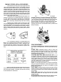
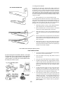
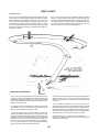
Your model was designed to use three or four- channel
radio control equipment. In flight, the model is primarily controlled
by using the ailerons and elevator (see sketch at left). One radio
channel controls the ailerons. This is the primary turn control - it
rolls the model. Another channel operates the elevator which controls pitch (climbing, level flight and descent). The third channel is
for the engine throttle and controls the engine speed. A fourth
channel is used for rudder which assists the ailerons for turning.
The new R/C flyer will probably only use the rudder for steering the
model on the ground. Note: for three-channel flying, ailerons are
not used and the rudder becomes the primary turn control.
Radio sets are battery powered with either dry cells
(small flashlight type batteries) or more reliable rechargeable
nickel-cadmium batteries (ni- cads). Sets powered with ni-cads
come equipped with a recharging unit, and are more expensive
than dry-cells sets. However, if you intend to do a lot of flying, the
cost of routinely replacing worn out dry cell batteries will be much
greater than the higher initial cost of a re-chargeable ni-cad radio
system; something to consider. Many of the radio systems now
available feature “servo reversing” switches which allow you to
reverse the response of the servo. This feature simplifies radio
installation and is a worthwhile consideration when selecting a
radio system. You may find radios with more sophisticated features such as dual rates, exponential and control mixing, etc.
These features are not needed for general sport flying, and are
typically used my more advanced flyers.
When selecting a radio, remember that there are many
radio frequencies available. Not all of these frequencies can be
legally used to operate model airplanes. Tell your dealer that you
want a radio with a model “Airplane” frequency.
DIGITAL PROPORTIONAL
RADIO CONTROL
WARNING: Per the Federal Communications Commission there
ONE OF MANY SYSTEMS AVAILABLE,
PLEASE SEE YOUR LOCAL DEALER OR
CLUB FOR ADVICE ON SELECTING
YOUR RADIO.
is only one group of frequencies designated for radio control aircraft use. According to the law, it is your responsibility to use the
designated aircraft frequencies to operate your model airplane.
2
ENGINE, PROPELLER & ACCESSORIES
Your plane flies well using any 2-cycle engine size from
.35 to .45, or 4-cycle engine .45 to .61. The numbers .35 to .45
refer to the amount of space the piston moves through inside the
cylinder of the engine. This space is called displacement; larger displacement generally means more power. If you live in a hot
climate, or your flying field is approximately 3,000 feet or more
above sea level, you should stay with a .45 engine. It’s a good
idea to select an engine that is popular at the flying field, so that
if you have any engine problems, other modelers will be familiar
with the engine and be able to help.
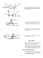
The propeller size must be matched to the engine. For
example, a .35 may use a 9” diameter prop while a .45 can use a
10” prop. Refer to the propeller chart below for recommended
propeller sizes. It’s wise to buy a few spare props, as everyone
breaks them occasionally, and particularly often when learning
to fly.
Balancing your propeller helps to protect your radio
from the damaging effects of the market. We recommend sanding the heavy blade on the curved face, out near the tip, rather
than on the flat face. Try to maintain the normal airfoil curvature.
Avoid scratches which may cause the prop to break. Never
carve or cut a prop near the hub for any reason (such as to fit a
spinner).
A 2¼” CGP Snap-On Spinner is recommended for the
Eagle. It is a rugged precision molded spinner which does not
require any special mounting nuts or screws. Although a spinner helps reduce the chance of injury from the rotating prop,
extreme caution always must be used when the engine is running.
As with other precision equipment, a new engine
should be "broken-in" to enhance performance and extend its
life. Breaking-in usually consists of running the engine with a
"rich" fuel mixture and at lower RPMs until all the moving parts
get to "know each other better." This can be done with the
engine mounted in the model or securely clamped into a CGM
Engine Test Stand or similar device. Refer to your engine's
operating manual for the recommended break-in procedure and
follow it carefully.
FIELD EQUIPMENT
The following equipment will be needed at the flying field to start
your engine, make adjustments, and clean your model after flying.
FLIGHT BOX: Something sturdy in which to carry your
equipment. CGP's SuperTote or ProTote are economical, easy to
build, and pack lots of utility into little space. They hold fuel,
transmitter, starter & battery, as well as many tools, in a balanced load that is easy to carry.
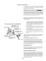
STARTING BATTERY AND GLO-PLUG CLIP: A 1-1/2
volt battery is required to heat your engine's glo-plug for starting. Wires connect the glo-plug clip to the battery. Because
engine starting draws a lot of electric power from the battery,
rechargeable ni-cad batteries are recommended. Although they
cost more initially, they are more economical in the long run
than frequently replacing dry-cell batteries.
FUEL: For best engine performance, use the fuel recommended by your engine's manufacturer. 2 and 4-cycle engines require
different fuel blends. Ask your dealer to recommend a good
quality 5-10% Nitro fuel.
FUEL PUMP: Needed to transfer fuel from the fuel can to the
model's fuel tank. A simple squeeze-type bulb will do for small
tanks, whereas manual crank or electric pumps fill larger tanks
more quickly.
FUEL LINE: Have about 3 feet of silicone fuel line to make
connections between the fuel pump, the fuel can, and the
model's fuel tank.
EXTRA PROPS: Experts always have a few spares on hand,
so flying doesn't have to stop due to a broken propeller.
Refer to the Prop & Fuel Tank Chart shown here for the
correct size fuel tank for your particular engine. There are many
sizes and brands available. Assemble your fuel tank according
to the manufacturer’s instructions.
3
INTRODUCTION
HOW TO USE THE PLAN
USING THIS INSTRUCTION MANUAL
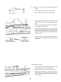
The plan is used in several ways. The wings, stabilizer,
and fin are assembled directly over the plan. Each wood part is
matched over its corresponding location printed on the plan and
pinned in place. To prevent ruining your plan from gluing your
wings, etc. to it, cover the area you are working on with waxed
paper.
The paper the plan is printed on can expand or contract
slightly with changes in temperature or humidity. Because of this, a
preformed part such as the notched wing trailing edge may not
exactly match the plan. This is no problem, as slight deviations in
the outline or size will not noticeably affect flight performance.
Before you start gluing and sanding, take some time
becoming familiar with the plans and looking through this entire
instruction booklet. It is designed to guide you through the construction process step by step, so build in the order given in this
book. Balancing, setting up and flying the model are also covered.
Like a full-size airplane, the EAGLE II is built from
basic structures (stabilizer, fin, wing, etc.), which are then
assembled into the complete airplane. Special procedures or
comments will usually be explained before a step, so you will be
prepared. If a step begins with a statement like “Note,”
“Warning,” or “Important,” it is a good idea to read through the
step before doing it.
Because the fuselage plugs together and is self-aligning,
it is not built directly over the plan. As you assemble the fuselage,
you will find the plan helpful in identifying parts and how things fit
together.
The plan also shows the installation of a typical radio, battery and
all remaining equipment and hardware needed to complete the
model. By referring to the examples shown, you should be able to
install your own radio, etc., even if it is not the same as what is
shown on the plan.
A check-off box appears at the beginning of each step.
Check these boxes as you build, so you can tell at a glance
what steps you have completed. Some steps are repeated and
must be marked twice, as in the case of the left and right wing
panel.
HOW TO READ THE PLAN
There is one plan sheet in this kit, showing the
Fuselage (Body), the Wing, and the Tail Parts. Everything on
the plan is drawn to full-size and shape and shows how the finished parts fit together.
IDENTIFYING PARTS
Parts for the wing are bundled together; likewise, parts for the tail
assembly are also grouped. Die-cut plywood and balsa sheets of
common sizes are bundled together, so they are less likely to be
damaged during shipping and handling. The various screws,
hinges, and fittings are packaged in plastic bags.
The plan is drawn to show the model completely
assembled, but as a result, the areas inside or underneath are
covered up, making it hard to understand how these parts fit
together. Therefore, for clarity, some parts are drawn with hidden lines, others with breakaway views, and some are entirely
removed from the structure and shown separately.
PREPARING FOR ASSEMBLY
Set a flat, warp-free pinning board on your work bench. Any material that accepts pins, such as insulation board, soft plywood, or drywall (sheet rock) will work. Important: any warps or bends in the pinning board will result in wings or tail surfaces that are also warped
or bent, making your model more difficult to fly. Make sure that the
pinning board is flat by laying a straight edge across it. You may be
able to correct a warped board by shimming its low areas.
Position the area of the plan (such as the stabilizer) on which you
are going to build over the pinning board and tape it in place so the
plan lays flat and wrinkle free.
Place a sheet of waxed paper over the work area to prevent
SUPER JET from sticking to your plan and ruining it.
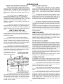
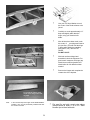
For example, on the fuselage, the left side of the completed model has been removed to show the details inside.
Sometimes a surface is broken away to reveal the detail behind
or underneath. Dashed lines indicate details that are hidden
behind or under another part of the surface.
FUSELAGE DRAWN WITH LEFT
SIDE REMOVED TO REVEAL
INNER FUSELAGE DETAILS
THE WING IS SHOWN CUT
THROUGH AT THE CENTERTHIS IS A “SECTION” VIEW
CONSTRUCTION TIPS
In assembling your model, the following tips will prove helpful.
IMPORTANT: ALWAYS READ A FEW STEPS AHEAD. This will
alert you to coming instructions and will help you plan accordingly.
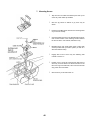
You may find it convenient to empty all of the small parts
from the hardware bags into a common container, such as a margarine tub. This will help you find items quickly.
Dashed lines show
a part “Hidden
behind the fuel tank.
Punch out only the die-cut (D/C) parts you need as you
proceed. This will help you keep track of parts, especially the small
ones.
After completing each section of the aircraft, you may want
to go back and re-glue the joints, just in case some area has been
missed. Be careful not to use too little glue, which will leave the
model weak, or too much glue, which can make the model heavy.
Properly glued joints are important to the overall strength of the
model. SUPER JET™ is recommended for most parts of the
assembly, although JET Epoxy may be used when more time is
needed for careful placement.
Fuselage side “Breakaway” view
to show how switch is mounted
The model is made from four varieties of wood: balsa,
bass, birch, and various plywoods. Each kind of wood has its
own characteristic end grain pattern (as viewed from the end)
which has been drawn on the plan. You can easily use these
end grain patterns to identify what kind of wood is shown for
that part, if you are in doubt.
4
ADHESIVES
The EAGLE II was designed for fast assembly using SUPER
JET™ glue, which is a specially formulated cyanoacrylate adhesive CA that can firmly glue the plywood, hardwood, and balsa
used in your model.
WARNING
Never use water THIN type CA glue for general construction of your
model, especially for gluing plywood and hardwood parts. Thin CA's do
not adequately bond these areas.
Although most of you construction should be done with SUPER JET™,
there are times, such as when you are installing the stabilizer and fin
on the fuselage and want more set-up time for careful alignment and
positioning, when you may wish to use SLOW JET™. And occasionally, you may also wish to use JET EPOXY™ for added strength.
Aliphatic resin glue or similar water-based glues can also be used, but
they will add to the assembly time because they dry so much more
slowly than SUPER JET™ GLUING TECHNIQUES
SUPER JET™ is strongly recommended for most building tasks
because, when pressed into a very thin layer, it sets almost instantly.
After the initial bond, SUPER JET™ continues to strengthen. However,
because of SUPER JET's™ quick set-up, you must be careful to read
instruction thoroughly, as you will have only moments for positioning of
parts. Be sure to trial fit pats together before gluing.
SUPER JET™ is used in two general ways. One is to apply SUPER
JET™ to one part and then press the two parts to be glued together. Or,
you can position parts in contact and then run SUPER JET™ into the
joint. As it seems into the joint, it will leave a slight reinforcing filler. If
you don't see a slight fillet, the CA has soaked into the wood edges and
a second coat is needed.
SUPER JET™ sets up a bit slower with plywood and hardwood, so hold
such parts together a little longer than you would for balsa. Comer fillets take even longer to dry because there is not a thin layer.
The tendency is for all CA glues to set slower on harder woods or when
in a thick layer. Corner fillets also take a while longer to dry. To speed
up such slow drying joints, use JET SET™, an accelerator for all brands
of CA glue. JET SET™ bridges greater gaps, speeds up slow bonds,
and provides string glue joint fillets
Epoxy glues come in two parts which need to be mixed before using.
When buying epoxy, check to see how long the glue takes to set We
recommend either JET 6 MINUTE EPOXY™ or JET 20 MINUTE
EPOXY™. Disposable wood strips, cotton swabs, cheap stiff bristle
brushes or acid brushed from auto stores make good applicators.
Because epoxy is so thick, it is easy to apply too much. Use sparingly,
especially when assembling the fin, stabilizer, and wings.
CAUTION
Some people may experience an allergic reaction when exposed to
fumes from CA glue or epoxy. As with paints, thinners, and solvents, it
is always important to use glues only where there is adequate ventilation to carry fumes away. A fan is recommended.
Also, special care must be taken when using CA, as it will bond skin as
well as other surfaces. JET DE-SOLV™ is a CA solvent which removes
hardened glue from fingers and softens glued joints for repositioning.
When using CA, protective eye-wear and care in keeping the glue away
from the face is highly recommended. If CA does happen to get into the
eye, hold lid open and seek immediate medical attention.
MAJOR COMPONENTS BEFORE COVERING
5
NOTE: In this kit version, D/C Sheets 5601, 5603, 5605, 5608 & 5609 have been
replaced with D/C Sheet 5611, 5612 & 5613 (shown below)
WOOD PARTS
ABOUT THE WOOD IN THE KIT
Be careful when removing parts (such as fuselage sides) from
the die-cut sheets. Long parts are fragile until Super Jeted into
a structural unit. If necessary, use a razor knife or razor saw to
assist in the removal of parts from the sheet. Sometimes a little
trimming and sanding can improve parts where desired. Save
scrap until the model is completed, in case a part is missing or
damaged. Also, scrap is used in some building steps.
We strive to supply good quality materials in your kit. Wood parts
are inspected with regard to the function they will serve. If an
imperfection is spotted in a scrap comer of a die-cut sheet and
doesn't affect actual parts; the sheet is considered acceptable
Also, internal stresses in wood are relieved as it is cut into parts.
These relieved stresses may cause some parts to bow. Bows in
wood parts (such as leading edges) readily straighten out as they
are Super Jeted into a structural unit
6
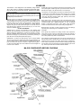
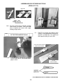
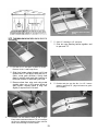
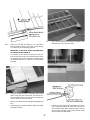
TAIL ASSEMBLY
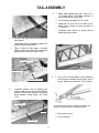
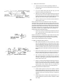
3.
Make stab leading edge (LE.) from 1/4" x
1/2" balsa sticks. Cut balsa carefully to
match with plan at center joint.
Pin in position and glue to L.E. Joiner.
Complete stab outline by gluing die-cut
balsa stab tips in place.
Make stab T.E. from 1/4" x 1/2" balsa. Cut to
match length shown on plan and glue to
T.E. joiner.
1. Set your flat warp-free pinning board on
work bench.
Tape Eagle plan so stabilizer (stab) is in
position over pinning board.
Tape a sheet of wax paper or plastic
kitchen wrap over stab area to prevent
gluing parts to the plan as you build.
Leading Edge Joiner
Center Platform
4. From 1/8" x 1/4" strip balsa, cut all trusses to
size over plan. Working one-at-a-time, trim to
fit well -don't force into place. Glue in place.
Trailing Edge Joiner
2. Carefully position die-cut leading and
trailing edge joiners and center platform
and pin in place over the plan. Glue these
parts together using Super Jet (Thick
C.A.).
Leading Edge
Jet set makes all brands of CA glue dry faster. Use
Jet Set on corner joints for extra-strong fillets.
Stab Tip
Glue gussets in place.
Let dry thoroughly.
Trailing Edge
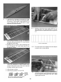
7
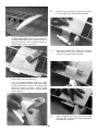
Place elevator on top of T.E. and transfer
hinge locations to elevator.
5. Position balsa elevator against stab T.E.
and mark elevator ends for match with
stab tips.
7. Assemble the fin in the same manner as
stab. Let dry.
Cut elevator at marks to match stabilizer
tips.
8. Mark hinge locations on fin and rudder.
9. Using the CG Center-Line Marker provided,
mark center lines along edges of parts as
shown. Tilt marker so guide pegs touch the
wood, then lightly pass the marker back and
forth. Point will scribe center line.
6. Transfer hinge locations from plan toT.E.
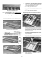
8
On Stab & Fin, Mark center
lines at hinge locations
Use your CG Hinge Marker to mark
the center of the wood surfaces to be
joined.
Carefully cut a slot approximately 1/2”
deep and slightly wider than the
hinge, using your favorite knife
blade.
After all slots have been made, mark
the center of
your hinge and insert a
pin (see illus.) This will hold the hinge
in place while sliding the matching
part (aileron, etc.) onto the JET
HINGE.
DO NOT GLUE!
With both surfaces hinged and
assembled, check the alignment. For
good control response, the hinge gap
should be as small as possible, but
should allow for full deflection when
needed.
Remove the hinges and complete the
construction of the airplane.
On elevator & rudder, mark
center lines along entire leading edge.
Note:
in the next few steps the hinges will be TEMPORARILY
installed - they are not permanently installed until after
the model is covered.
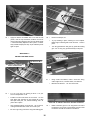
9
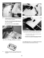
Flat sand fin and stab, round outer edges
(except bottom & lower 2" of fin L.E. Sand
elevator tips to blend with stab.
ASSEMBLING DIE-CUT BEVELING TOOLS
(FROM 1/8” PLY)
Wide Strip
Narrow Strip
14a. First glue narrow strip to handle, keeping
them square, as shown. Then glue wide
strip to handle and narrow strip, again
keeping things square.
15. Tape T.E. of elevator and rudder to work
surface. Using appropriate beveling tool,
sand LE. to center line. Turn parts over
and repeat beveling for other side.
“EA” Tool used for elevator
(Later used for Ailerons
14b.
Cut two strips of 100-200 grit sandpaper
to size shown above. Tack-cement sandpaper to tools.
“R” Tool
Used for Rudder
THIS COMPLETES THE TAIL ASSEMBLY CONSTRUCTION.
10
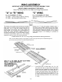
WING ASSEMBLY
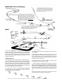
IMPORTANT! READ THIS BEFORE STARTING ASSEMBLY YOUR
EAGLE'S WING CAN BE BUILT TWO WAYS
Select The Wing That Fits Your Radio and Flying Requirements.
"A" or "B" WING
"C" WING
For 4-CHANNEL FLYING
For 3-CHANNEL FLYING
"A" WING — Aileron Wing for Sport & Training
"B" WING - More Aerobatic Aileron Wing
High Dihedral Wing for Control Without
Ailerons
Because the "C" wing has greater dihedral angle, it
inherently is more resistant to banking, and more responsive to being turned. The model is turned by the rudder,
which then reacts against the dihedral. The "C" wing is
recommended for 3-channel equipment, or if you want to
keep things simple, or for learning to fly without an
instructor.
The Ailerons, the movable control surfaces at the trailing
edge of the "A" or "B"wing; allow more precise control of
maneuvers, The "A" wing has average dihedral (the
upward bend of the wings), and is quite stable and
maneuverable. The "B" wing has very little dihedral (it is
almost flat), which decreases stability slightly, but
increases stunting ability. It is recommended for experienced flyers only! Ailerons require 4 (or more) channel
equipment, and more work in the wing construction.
To build either the "A", "B", or "C" wing, simply proceed with the following instructions.
After you have finished gluing the wing together, go back and re-glue all the joints for added strength and
just in case some joints may have been missed the first time.
1. THIS STEP FOR "C" WING ONLY (for "A" or "B"
wing start with Step 2). Align aileron and inboard
section along any straight line on plan and pin in
place. Glue them together. Glue trailing edge (T.E.)
to aileron & inboard section. Note; from Step 4 on
in the wing assembly photos & sketches, the "A""B" wing is shown (ailerons not glued to T.E.). but
the wing assembly procedure is the same for the
"C" wing.
11
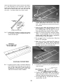
SINCE THE WING IS BUILT IN TWO HALVES, AND STEPS 2
TO 14 ARE REPEATED IN THE PROCESS, TWO CHECK
BOXES ARE PROVIDED WITH EACH OF THESE STEPS,
ONE FOR THE RIGHT WING HALF AND ONE FOR THE
LEFT HALF. THE RIGHT WING HALF IS BUILT FIRST.
Do not glue rib no. 2
at this time.
Rib scrap
wood
No notch
here
1/8” ply T.E. brace
3. Using no pins, set TRAILING EDGE (T.E.) in place
on plan. IMPORTANT: The T.E. has no notch at one
end — this unnotched end must be at the wing center as shown.
Using no glue, place the following four ribs in
their respective T.E. notches: ribs Nos. 2. 4, 4,
& 4, hooking them over the spar as you go.
Place rib wood scrap under rib 2 as a shim.
2a. IMPORTANT! Compare the leading edge dowels
Align T.E. and ribs over plan, and pin in place,
(Note: if a part appears not to "fit" the plan
exactly, don't worry; this is due to expansion
and shrinkage of the plan paper).
to a wing spar If dowels are longer than spar, cut
dowels to match spar.
Do not glue rib No. 2 at this time. Glue ribs
No.4 to T.E. and spar.
Glue 1/8" x 7/16"" x 3-9/16" ply T.E. brace to
T.E. as shown. Note: four 3-9/16" pieces are
provided; two are T.E braces & the other two
are later used as servo mounting rails.
Do not glue rib no. 2 at
this time.
4. Position rib 3 in place over plan, and glue it to T.E.
2b. Position one spar in place over RIGHT WING (or
brace and spar.
LEFT WING) on plan. Align spar end at center of
wing on plan. Hold spar in exact position by
crosspinning at circled locations on plan. CAUTION; Do not build two RIGHT WINGS!
Position 30" LEADING EDGE (LE.) dowel in
place over plan. Press L.E. into rib recesses,
holding it tight with angled pins as you go.
Do not glue Rib No. 2 at this time. Glue rib 3
and ribs No. 4 to LE.
12
Flush
Flush
Hold parts down flat when
gluing
7. Glue L.E. sheeting to L.E. and spar.
Glue two rear sheeting halves together, and
to spar and T.E.
5. Pin end of L.E. and spar in place as shown .
Remove rib No. 2 and scrap shims.
Slide front bottom sheet forward until it just
touches the L.E, and align it with end of L.E.
(Note wood grain direction). Gently hold
sheet in position and mark spar location on
both rear corners of sheet with your knife.
Remove sheet from wing, and using metal
straight edge, cut a One across sheet at
spar "marks." Replace sheet in wing, trim
slightly if required until it fits well.
8. Position and glue two ribs No. 2 to L.E., bottom
sheeting, spar and T.E. (align rib fronts over guide
lines on plan).
6. Position one rear bottom sheet at rear of spar.
Place other rear bottom sheet at T.E, so it overlaps
the first one. Holding both sheets in place, trim first
sheet even with edge of second sheet.
13
9. A doubled rib is necessary at the wing tip so that
when you cover the wing, the tip rib won't bend.
Glue two No. 4 ribs together: apply SUPER JET to
one rib, stand them next to each other to check
alignment, then press together.
Do not glue any new ribs to the
L.E. at this time.
12. Working a few ribs at a time, apply SUPER JET to
glue loose ribs to L.E. Gently squeeze LE. into ribs
and hold until set. Repeat until all ribs are glued to
L.E.
10. Glue double thickness rib No, 4 in place at
wing tip, gluing to spar and T.E. only. Hold rib
straight up until it sets.
Laser cut sheet 5600
Working one at a time, glue remaining ribs
No. 4 to spar & T.E. only. Hold each rib up
straight as it dries.
13. The shear webs to be installed in the next step are
located on die cut sheet #5600.
Cut web height for sheeting clearance.
11. Three set-back gauges are supplied, one for "A",
one for "B", and one for "C" wing. Position proper
gauge touching bottom spar. Touch end of top spar
to gauge, and set spar in rib slots.
Glue top spar to all ribs.
Glue wing tip gussets to L.E. and T.E.
13a.Install pre-cut webs in wing at positions shown on
the plan as follows: Apply two beads of glue (along
top and bottom), then press web up in place
against spars until set.
14
15. WEBS MUST BE INSTALLED BETWEEN ALL RIBS
REFER TO PLAN FOR ALL WEB LOCATIONS.
For "A" wing, gauge end "A" must be up.
For "B" wing, remove shaded area of gauge (as shown
at left).
For "C" wing, gauge end "C" must be up.
Hold gauges firmly to the ribs by tack-cementing or stationary
clamps, clothespins, etc.
13b. Continue gluing webs to spars at locations shown on
plan; cut 1/4" off webs next to center sheeting.
14. With left wing still pinned down, position RIGHT WING
in place next to it. Raise RIGHT WING tip and support it
at 4th rib in from tip using dihedral gauges. NOTE:
gauge ends are stamped, "A," "B" and "C."
Joiner clamps
Repeat steps 2 through 13 for LEFT wing.
READ THIS STEP THOROUGHLY BEFORE GLUING!
IMPORTANT:
“A” at top for “A” wing.
Dihedral Joiners
“A” wing only!
16. Study entire center joint; all end parts of right wing
should just touch those of the left (tiny gaps are alright).
If the fit between most parts is a little loose because one
part protrudes too much: slightly sand only the protruding part for better fit. When sanding, it is better to take
off too little than too much!
TEMPORARILY set dihedral joiners in place on each
side of spars, using die-cut clamps provided to hold joiners tight against spars.
Be sure RIGHT WING is held firmly against LEFT WING
and pin in place as shown above. Remove joiners.
17. Apply a liberal bead of SUPER JET to joints of L.E.
spars, sheeting, and T.E.
SUPPORT WING AT 4th RIB IN FROM TIP
IMPORTANT:
“B” at top for “B” wing.
“B” wing only!
SUPPORT WING AT 4th RIB IN FROM TIP
IMPORTANT:
“C” at top for “C” wing.
“C” wing only!
SUPPORT WING AT 4th RIB IN FROM TIP
15
Position “T2” stamp
near spar.
18. 20. Apply two ribbons of SUPER JET to one side of both
joiners, near the top and bottom, Position one end of
joiner in place and swing the other end up against spars
— hold momentarily. Repeat for other joiner — immediately reinstall clamps (from step 16) to hold both joiners
tight on spars.
Remove all clamps, etc.
Try top sheeting in place, trimming to fit as required.
Match edge of sheeting with center of rib No. 1. Glue in
place.
Turn wing upside down and glue any joints still needing
glue. For "C" wing only, proceed directly to step 34a.
* IMPORTANT I *
SEE BOLT-ON WING OPTION
Wing upside down
1/8” Balsa rib No. 1
*For bolt on wing option only*
Glue T.E. filler blocks
1-1/2”
21. 19. For "A" or "B" wing, cut opening in rib No. 1 for your
servo at stamped line on rib.
Position front and rear halves of one rib No. 1 so one
side aligns with centerline of wing. Adjust rib to align
with spar center joint, T.E., bottom sheeting, and L..E.
joints. Glue in place.
Glue remaining halves of second No. 1 rib to first rib,
making double thickness center rib at center joint.
Be sure to glue any joints in the wing still needing glue.
Using Center Line Marker, make a center line along
entire lengths of T.E., inboard section, and ailerons.
Mark front of ailerons 1 -1/4" from inner ends.
Ailerons & inboard sections shown reversed
22. 16
Make a clearance groove 1-1/4" long at the inner end of
the ailerons. The groove must be deep enough so that
the aileron wire wilt lie recessed in the aileron.
23a.
24. Cut 1-1/4" off wing tip end of ailerons, and glue to T.E.
flush with end of T.E. as shown above.
Position ply horn angle gauge at threaded end of horn
wire, slowly press aileron on other (3/8" long end) of
wire to make a mark. With a small nail, make a hole for
the wire Work carefully, keeping hole centered inside
aileron. Repeat for other aileron.
Place wing over plan and mark T.E. for nylon aileron
bearing locations. Using a razor knife, cut slot through
T.E. center-line for each bearing glue tab.
IMPORTANT: IN THE NEXT STEPS THE WING MUST
BE TURNED BOTTOM SIDE UP.
Cut a clearance slot 1/2" from center joint in wing T.E.
and 1/2" from inner ends of T.E. inboard sections. These
are clearance slots for the strip aileron wires-they allow
the threaded end ("horn") of the wire to rotate forward
and back.
23b.
Using NO GLUE AT FIRST, temporarily slide bearing
tabs in wing slots and position both T.E. inboard sections over aileron wires. Check for "horn" movement-top
to move about 3/4" total fore and aft.
Remove TE. inboard sections and glue bearing tabs into
wing.
Carefully glue TE. inboard sections in place (CAUTION:
Keep glue off wires).
17
So ailerons don’t fit tight after everything gets covered,
gently sand both ends of aileron. The clearance is correct when you can fit each aileron in place with a piece
of matchbook cover (about 1/32") at both ends.
Place TE. on plan and mark hinge locations (three
hinges per wing half).
Transfer hinge locations to ailerons.
18
26. Temporarily fit ailerons in wing with hinges, checking for
hinge alignment.
27. Using beveling tool "EA", bevel front edge of aileron to
centerline. Turn aileron ever and repeat sanding.
Repeat for other aileron.
28. 30. Glue one end of 2½" wide nylon fabric to scrap wood.
Let dry until the nylon is glued solidly to the balsa.
31. Apply a line of SUPER JET at center joint on wing bottom and stick one end of 2½" wide nylon to it. Let dry
until the nylon is glued solidly to the balsa.
32. Apply a squiggle of glue to wing and pull nylon fabric
into it. Rub nylon into glue with your finger (cover finger
with plastic bag or similar).
Lightly sand plastic wing tips to remove burrs from precut edges. TEMPORARILY fit tips in place (they are permanently installed after wing is covered as shown on
page 39). If they bind at T.E., try gently forcing them on,
or sand a slight recess for them in T.E.
29. Using 240 grit (fine) sandpaper, flat sand entire wing to
blend surfaces and remove high spots.
Cut 1" x 6" half-hard aluminum sheet into 3" pieces
Lightly sand aluminum surfaces for better gluing. Apply
a bead of SUPER JET to half of a 3" aluminum sheet
and glue it to wing T.E. as shown.
When dry, apply
glue to other halt and then wrap it around T.E. Repeat
for other 3" piece.
19
35. 33. Repeat gluing procedure and apply nylon around L.E.,
across top of wing, around T.E. and finally overlapping
where you started on wing bottom.
After entire center joint has been wrapped with nylon,
apply another coat of glue and force it down through the
nylon. Let dry thoroughly.
Carefully position servo 1/2" behind bottom spar and
mark size for opening.
THIS COMPLETES THE "C" WING ASSEMBLY
THE SERVO RAILS SHOWN IN THESE PHOTOS HAVE BEEN
REPLACED WITH THE PLY MOUNTING TRAY (STEP 34).
Cut-out bottom sheeting. Remove material from rib No.
1 as required to suit your servo.
Glue servo tray to wing,and fill any gaps under the tray
with slivers of scrap balsa. Avoid getting glue on servo!
For “A” or “B” wing, slit fabric over horns.
THIS COMPLETES THE "A" & "B" WING CONSTRUCTION.
The servo should be removed before covering.
34. Temporarily mount servo in die-cut mounting tray. See
fuse side view on plan for added details of aileron servo
installation.
20
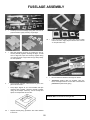
FUSELAGE ASSEMBLY
1.
Carefully remove all fuselage (fuse) parts from die-cut
plywood sheets. Lightly sand any rough edges.
3b. 2.
With side stamped "A" facing out, position two 1/8" ply
formers (firewall) together, matching all edges, To hold
them in alignment, tape them securely together along
one edge as shown at right. Have four ply clamps ready
for next operation.
4.
3.
From 1/8"x1/2"x18" balsa, cut and glue strips to match
formers as shown. Apply strips as shown. Note: Former
"C" strip at bottom only.
Open firewalls and apply a liberal bead of glue to one
part as shown at left.
Keep edges aligned as you close firewalls and tape
opposite edge together. Squeeze firewalls together
using die-cut clamps. When dry, remove clamps and
tapes; set clamps aside for use later.
Be sure sides are laid down left & right as shown.
Temporarily position cabin top doublers, nose doublers, and engine bearers on fuse sides. Check fit and
placement of parts before gluing.
NOTE: Cabin top doublers MUST be flush! Holes must be aligned.
WARNING! Make one left side and one right side!
3a. Repeat firewall joining procedure and make doubled
Former "B".
21
5b.
To prevent oil penetration, seal area around
four holes as follows. Apply a bead of
SUPER JET and smear it into the wood with
your finger wrapped in plastic bag.
Nose Doubler
Flush
Align Holes
Engine Bearer
SMALL TRIANGLE SHAPED PIECES SHOWN ABOVE HAVE
BEEN ELIMiNATED FROM THE KIT, THEY ARE NOT NEEDED
Install nylon nosegear bearing on firewall
using #4-40 x1/2" machine screws and nuts
as shown.
Place a drop of SUPER JET on nuts to lock
them in place.
7a.
Position two 1/8" ply breakaway plates
together, matching all edges including center
cut-outs, To hold them in alignment, tape
them securely together along one edge as
shown .
7b.
Open plates, and apply a liberal bead of glue
to one plate as shown.
6.
Glue nose doublets to body sides, making sure to
flush pans as shown
Glue engine bearers solidly to fuse sides and edge of
nose doublers (longest edge to be glued to fuse side).
Glue cabin top doublers in place on fuse sides.
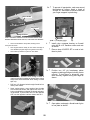
5a. Drill two 3/16" diameter holes through firewall at
upper punch mark locations as shown above (place
scrap wood under backside while drilling to avoid
split out).
Drill four 1/8" diameter holes through firewall at four
lower punch marks.
Study engine above; most engines have throttle
arm on the side shown, and require two more 1/8"
holes to be drilled as indicated for throttle and steering pushrods, If your throttle arm is on the opposite
side, use the opposite locations shown with an X.
22
7c.
Keep edges aligned as you close plates and
tape flanges together. Squeeze plates together
using clamps. When dry, remove tapes and
clamps. Set aside.
8c.
insert top sheet under rubber band at former
C, and work it towards tail, slipping it under
bands as you go.
8d. Lock tabs at both ends of top sheet into corresponding notches in fuse sides.
Position stab platform between fuse ends,
and hold parts in place with rubber bands.
8a. Place fuse sides one on the other, and tape
rear together around the back end. Spread
fuse fronts apart, and plug former "B" into
holes in body sides. Hold parts together with
a rubber band. Carefully spread fuse rear
open, and plug former "F" in place, and hold
with a rubber band. Remove tape from tail
end.
8e. Position front and rear bottom sheets in same
manner.
8b. Install firewall & remaining formers "C", "D",
and "E" in same manner, using rubber bands
to hold parts.
23
9. Place fuse over TOP VIEW on plan sheet.
Viewing from above, carefully align the fuse to
match plan outline. If an area of the fuse is off,
adjust that portion in the direction required.
11. Glue windshield top former and dashboard
solidly in place.
12. Tape hatch cover and dashboard fop together
(as they fit from die-cut sheet).
10. When satisfied with alignment, permanently
glue sides, formers, and sheet parts in place.
Apply a bead of SUPER JET along all joints
inside and outside, or from both sides in the
case of farmers — it will penetrate the joint
and leave a slight reinforcing fillet.
24
14. Remove hatch cover from fuse. Refer to plan for correct
placement of ply tongue, then glue tongue to hatch
cover. Try in place.
Glue dashboard top to hatch supports and dashboard.
12b.
Tape hatch supports to both sides.
15. Place the landing gear (L.G.) mount on inside bottom of
fuse. The cutouts at each end of mount must be positioned evenly over the slot in the fuse bottom, Glue
mount in place.
13. Position taped parts in place on fuse. Because of curvature, the hatch supports can overhang the sides slightly
(the overhang to be sanded off later.) Glue only the
hatch supports to the body sides.
16. The L.G. braces interlock with L.G. mount. Glue braces
solidly to fuse sides and L.G. mount.
25
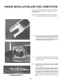
ENGINE INSTALLATION AND FUSE COMPLETION
For clarity, the engine installation is shown in many small steps
rather than a few general ones, It is not difficult — just thoroughly explained.
NOTE: 4-Cycle engine installations are shown on next page.
1. Mount propeller and spinner (if used) on your engine.
2. Tape breakaway plate on engine bearers. IMPORTANT:
The cut-out in the breakaway plate is purposely cut on
an angle, The letter "R" on the breakaway must be on
the Plight side as shown. The “Right” side is thought of
as it would be to a pilot sitting in the cabin.
3. Position engine on breakaway so there is approximately 1/8" between fuse front and spinner back (or propeller
if spinner isn't used.)
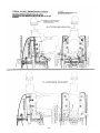
3a. Notice the engine in the top view on the plan is angled
slightly to the right. This "RIGHT THRUST", although
small, is important.
View your model from above, and carefully measure distance from tail end to one propeller tip (propeller must
be horizontal). Then measure other side of model in
same manner. Left side distance should be about 5/16"
longer than right side. For example, if right side measures 45-3/8"", left side should be 45-11/16". Add 2-3
drops of SUPER JET to hold engine temporarily in
place.
LEFT SIDE DISTANCE SHOULD BE 5/16"
LONGER THAN RIGHT SIDE
26
27
4a. Mark straight down through engine mounting holes onto
breakaway plate.
4b. Remove engine and breakaway plate from fuse. Drill
four 1/8" holes through breakaway at engine mounting
hole locations (place scrap ply under parts when drilling
to avoid splintering.)
5. Permanently install four blindnuts in bottom of break
away using socket head screws (and washers) to pull
blindnuts up into the screw holes as shown . Remove
screws after seating blindnuts.
6a. On die-cut lines, mark cross lines about 1/4" ahead of
and 1/4" behind holes as shown.
28
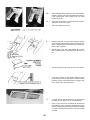
6b. Tape breakaway plate in position. At one of the locations
marked in step 6a, drill a 1/8" hole straight down through
it and engine bearer. Insert a #4-40 x 3/4" soc. head
screw through hole.
6c. Continue this procedure, one hole and screw at a time,
until all four screws are in place.
7. Remove breakaway from fuse.
8. Position hatch cover on fuse. Press hold-down against
front of firewall and up against bottom of hatch cover as
shown. "Straight action" end should point towards fuse
bottom. Tape in position.
Remove hatch cover and apply SUPER JET to holddown. Replace hatch on fuse, gluing it to hold-down. Let
dry.
Secure hold-down to hatch with two #2 x 3/16" screws.
Set hatch in position on fuse. Mark location as shown
for #2 shoulder screw. Install screw in marked location,
exposing enough unthreaded shank to engage holddown. Snap on and off several times.
9. Carefully remove side windows from vac-formed sheet
by cutting on lines (about 1/4" all around windows).
Using no glue at this time, temporarily fit windows into
fuse openings. If they fit too tight, causing them to bulge,
remove and lightly sand openings the minimum required
for good fit. Remove windows from fuse and set aside
until later.
29
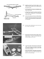
10a. Temporarily install wing hold-down dowels in fuse.
Rubber band wing in place on fuse, making sure it is
centered. Viewing model from rear, see if stab sets level
with respect to wing.
Sand stab platform area as may be necessary to provide a good level fit for stab. Do not alter the die-cut
angle of the fuse sides.
Center stab on fuse, measuring to obtain equal distance
from side to side, and from nose of fuse to rear corner
of each stab tip ( see dimension "C" in Final Assembly
section). Pin in place.
10b. There are two "bumps" at ends of 1/4" balsa dorsal fin.
The bump at the short end must be cut off (the other
bump fits into fuse notch). Watch grain and very carefully trim it off. Smooth this edge with a few light passes of
the sanding block.
10c. Trial fit fin in place. Glue dorsal fin to main fin but not to
fuse, as shown. Finish sanding.
11. Flat sand fuse and round off corners, except in the following areas: top of cabin, top of tail mounting area, and
window openings — repeat: do not sand these areas,
except very lightly to remove burrs!
12. To protect the engine and tank areas from becoming oil
soaked, they need to be "fuel-proofed". Either polyurethane enamel, SUPER JET, or epoxy, is good for this.
Poly urethane is available in colors so you can match
close to your color scheme.
Apply your fuel-proofer to entire engine area and breakaway plate, inside tank compartment, and bottom of
hatchcover. Open up screw holes with toothpick while
paint is wet. Let dry thoroughly.
30
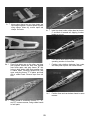
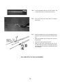
13a. From the threaded end of two 10" rods, measure and
cut one of the rods to 7" and the other rod to 4½".
13b. At cut end of rods, bend down about 1/4" making a
square hook.
13c. Using the threaded end of a rod, file a slight recess 1"
long at one end of each 5/16" square x 24" balsa pushrod .
Drill a 1/16" diameter hole 1/4" deep at end of recess in
both pushrods.
Glue rods into balsa pushrods as shown.
When dry, taper ends of pushrods and round off corners, Bind with strong thread, coat with glue and let dry.
The other end of the pushrods is completed later during
radio installation .
THIS COMPLETES THE FUSELAGE ASSEMBLY
31
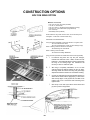
CONSTRUCTION OPTIONS
BOLT-ON WING OPTION
Materials not included;
Two 1/4"x 20 nylon wing bolts (CG #585)
1/4" dia x 3" wood dowel
Two 1/2" x 5/8" x 2" hardwood blocks (fuselage mounting)
Two 5/8" x1"x 1-5/8" balsa blocks (wing filler block)
One 1/4x20 tap
Klett Safety Driver (CG#610)
NOTE: A Bolt-On wing looks neat and clean, but is more likely to be
damaged in a crash than a rubber-banded wing.
MAKE THE FOLLOWING PARTS:
Using the full-size templates on Wing Plan Sheet 2 as a guide, make:
Two 1/8" balsa Number 1 Ribs.
Two 1/8" plywood Number 1 Ribs (out from fuselage scrap).
Refer to drawing at left for dimensions and make:
Two balsa Wing T.E. Filler Blocks.
Refer to drawing at left and make:
Two hardwood Fuselage Bolt Blocks
Wing Procedure (substitute the modifications below where applicable).
1. For Bolt-On wing there are only two part changes,
instead of the 5/64" die-cut No. 1 Ribs, use the new 1/8"
balsa No. 1 ribs. Balsa filler blocks must be glued inside
the wing at the Trailing Edge. The instructions will
remind you when to add these parts.
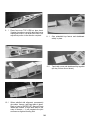
2. After wing is completely assembled, cut a 1/4" wide
opening through the bottom sheeting for the 1/4" diameter wing dowel. Glue dowel into wing and glue wedge
shaped filler between dowel front and bottom sheeting.
3. Cut two 1/8" wide slots through wing bottom sheeting on
either side of dowel location. Apply epoxy or Slow Jet to
side and top edges of 1/8" plywood rib, and slide it into
position next to rib 1 and dowel. Glue remaining rib to
opposite side.
Glue scrap 2-1/2" wide nylon fabric around dowel and
ply ribs up around wing bottom.
32
FUSELAGE PROCEDURE
1. Position and glue two hardwood mounting blocks
securely inside the fuselage as shown using Epoxy or
Super Jet. Glue them well, these glue joints must be
strong.
2. Drill a 1/4" diameter hole through former "B". Locate
hole by holding drill up against bottom edge of cabin top
doubler and then drill through former at a slight angle so
hole matches downwards slant of dowel.
3. Cut and glue two centering filler blocks under windshield
top former as shown, allowing center clearance for
dowel.
4. Position wing on fuselage and press T.E. down to rest
on fuselage top. Measure for equal distance from wing
tips to rear end of model and adjust wing so it is setting
square on fuselage. Hold wing in place with tape.
Measure 2" from wing TE. and 1/2" in from fuselage
sides. Drill two holes 13/64" diameter down through
wing and fuselage mounting blocks.
Remove wing. Enlarge WING
HOLES ONLY to 1/4"
dia.
Cut threads in FUSELAGE HOLES with 1/4-20 tap.
FINAL FITTING. After applying optional foam wing seating tape the wing may not fit in place. To correct this, file
dowel hole slightly higher (towards fuse top) using a rattail file. Continue until wing fits flat on top of fuselage.
33
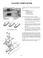
ELECTRIC POWER OPTION
ELECTRIC flying is clean and quiet. There is no messy engine exhaust
oil so your model stays clean. The items below are available from Astro
Flight Inc.
ASTRO GEARED 25 COBALT MOTOR
Materials not included:
Cobalt 25 Electric Motor (Geared)
Electronic Speed Control
Three 1200 MAH batteries
Three Battery Switch Harness
"Beam" type motor mount
DC Charger (for field charging)
The following modifications must be made to your Eagle:
ASTRO
ELECTRONIC MOTOR
SPEED CONTROL
1. Use a coping saw to cut two "U" shaped notches in the
SWITCH, CHARGER,
AND CONNECTOR
HARNESS
top of the firewall as shown, one (or each motor wire,
These openings provide for easy installation and access
to all electrical connections and cooling for batteries.
2. Cut the ply breakaway plate into two mounting rails to
dimensions shown in firewall front view.
Now install the electric motor, switch/connector harness
and batteries as shown in the illustrations. The Astro
Flite Cobalt .25 Geared Motor system as shown here is
recommended.
IMPORTANT! Read and follow the manufacturer's
instructions regarding the installation and safe operation
of each component of your electric motor system. The
motor, batteries, etc. are very powerful and must be
operated as recommended by the manufacturer.
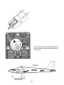
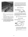
THREE 1200 MAH BATTERY PACKS
Three 1200 MAH battery packs are required for power, These batteries should be installed under the wing balance point as shown
and braced with plywood strips so they cannot move inside the
fuselage, Recharging the batteries is accomplished through a
jack mounted next to the motor On/Off switch. Recharging can
take as much as 45 minutes. Batteries should always be allowed
to cool before charging -cool batteries accept more charge than
when warm.
IMPORTANT! Read and carefully follow your battery charger
instructions, improper charging can ruin your batteries.
34
As the motor uses battery power the batteries will become
warm. Cooling air enters through the firewall openings and
exits the fuse tail end. In flight, this air movement will help
cool the batteries.
35
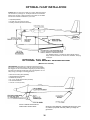
OPTIONAL FLOAT INSTALLATION
FLOATS make any large pond or lake your runway. Water flying adds a
new dimension to your flying fun. CG Super Floats are recommended
because they are easy to build and perform well. Floats can be added
at a later time with little modification to your model.
Superfloats(CG#296)
Two 5/32" dia. x 36" wires (for struts)
Finishing materials (see float instructions)
CG "SUPER FLOATS." A complete kit, easily adapted to fit the
Eagle, Includes information on construction, installation, and flying
techniques.
OPTIONAL TAIL WHEEL INSTALLATION
(Materials not included)
TAILDRAGGER. Tail draggers are especially well suited for flying
from rough or unimproved runways (use the next size larger wheels).
Tail draggers are not recommended for beginning flyers because they
are a little more difficult to handle than nose wheel airplanes. You can
easily change your Eagle to a tail-dragger later on.
Klett .40/.60 Landing Gear (CG#256)
Tail Wheel Bracket (CG#460)
#4 Blindnuts (CG #571)
No. 4 x 1/2" Socket Head Screws (CG #504)
3/4" diameter tailwheel
1/16" dia. x 6" wire (for strut)
MOUNT LANDING GEAR DIRECTLY
UNDER WING LEADING EDGE
We show a fixed tailwheel. A steerable tail wheel isn't needed; a blast of propwash will easily rudder your Eagle for
ground taxi.
36
GENERAL. Any irregularities in the wood surface will
show on the covering, so a good covering job should
be preceded by careful sanding, filling of nicks and
dents [we recommend CGM Model Mate™ balsa filler),
and then more sanding. For this final sanding, use fine
sandpaper (240-320 grade) and a sanding block.
The easiest way to finish your model is to cover it in
one color of UltraCote and then apply trim in a second
color, using either UltraCote or sticky-back UltraCote
plus. Both UltraCote and UltraCote plus can be applied
on top of each other without forming gas bubbles. (If
you use another brand of covering, follow manufacturer's instructions.)
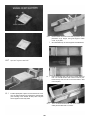
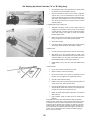
Using a fresh model knife blade or razor blade, cut a
piece of covering material at least 1" larger than onehalf of the inboard wing bottom panel.
You may also paint over polyester plastic films, as well
as the plastic parts of your aircraft, using modeling
grade polyurethane or epoxy paints. We recommend
UltraPaint one-step epoxy to best coordinate with your
favorite UltraCote colors. For good paint adhesion,
make sure the area to be painted is washed clean, dry,
and completely free of any oil or dust. When painting on
plastic covering, you may wish to dull the surface to be
painted with 000 steel wool. Mask the design with vinyl
tape.
Remove the protective backing paper and lay the covering over the bottom of the wing, making sure there is a
slight excess for wrap-around at the L.E., T.E.,and wing
tip.
NOTE: Before starting, it's a good idea to do s lay
out of the covering pieces you will need to
cut from the covering rolls, so that you
make efficient use of your material. You can
draw patterns on UltraCote's paper backing,
Be sure to leave a little extra material, so
you can go around the edge of the section
you are covering.
When using UltraCote, work from the center out and
tack to the ribs, sheeting, and other wood surfaces,
using medium heat. Gently rub the covering with a soft
cloth to set it in place.
COVERING THE WING
Before starting, carefully read the instruction that come with
your covering. You will cover the bottom of the wing first,
and then cover the top.
Set the covering iron to the proper temperature. Test it
by laying a small strip of covering over a scrap piece of
balsa and firmly pressing with the iron. Make sure the
iron is hot enough to activate the adhesive, but not so
hot that it bums the covering.
37
For best results, a darker color should go over a lighter
one. Smaller designs should be positioned and tacked in
place at one end. Then, work the iron down the rest of
the design, smoothing out the design as you go. Larger
designs (such as sunbursts) should be positioned and the
widest end tacked down first. Then, working towards the
narrow end, iron the design down.
INSTALLING WING TIPS
For inside comers, slit covering and fold it around the
relatively high heat, shrink the covering tight. Neatly trim
off any surplus.
For better bonding of plastic wing tips, use a pin to make
a series of many punctures through the UltraCote® into
the top and bottom edges of the tip ribs. In addition, lightly sand the inside edges of the plastic wing tip in the area
that will contact the tip ribs.
Following the same procedure, cover the remaining
Apply a bead of SUPER JET to the top and bottom
edges.
Using your iron (or a special covering "heat gun,") set at
edges of the tip ribs and slip the plastic wing tip into
place.
wing sections, both top and bottom. Be sure to overlap seam at least 1/4". The ailerons should be covered
in the same manner, beginning with the top and then
covering the bottom, and overlapping the seams.
TRUING THE WING
NOTE: Once the aileron sections have been covered,
and while the hinge locations are still fresh in
your memory, immediately slit the covering to
open up the hinge holes. (Refer to the plan for
help in locating the hinge holes.)
After the wing has been covered, you must check to
make sure it is free of warps.
Truing the wing Is an important step,
and should not be rushed or omitted.
Set one half of the wing on a flat surface to detect warp.
To counter any warp, twist panel slightly in the direction
opposite to the warp and hold position while gliding iron
over the covering to re-tension the structure. Repeat
process until the panel is true.
Follow the same procedure with the other half of the
wing.
38
COVERING THE TAIL
COVERING THE FUSELAGE
Following the same procedure as with the wing, cover the
stabilizer/elevator and the fin/rudder. After covering over
the hinge holes, immediately go back and slit the covering to open the holes where the hinges will be installed.
For added realism, the cabin interior may be painted now.
Use any of the paint materials recommended on the inside
front cover of this book; even gray auto primer will do.
Then proceed with covering the fuselage.
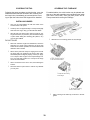
INSTALLING HINGES
Use your CG Hinge Marker to mark the center of the
wood surfaces to be joined.
Carefully cut a slot approximately 1/2" deep and slightly
wider than the hinge, using your favorite knife blade.
After all slots have been made, mark the center of your
hinge and insert a pin (see illus.) This will hold the hinge
in place while sliding the matching part (aileron, etc.)
onto the JET HINGE.
Mark and cut out covering pieces for the fuselage.
DO NOT GLUE!
With both surfaces hinged and assembled, check the
alignment. For good control response, the hinge gap
should be as small as possible, but should allow for full
deflection when needed.
When all the parts are ready for hinging then remount
the hinge with a pin inserted in the center, when satisfied that all parts are aligned properly, remove pin. Apply
3 to 4 drops of thin CA glue to the exposed hinge line.
Turn over and apply another 3 to 4 drops to the hinge
line of the other surface.
Apply covering to hatch top.
Cut corners and slit sides.
Allow 10 minutes for the CA to cure, before flexing the
surface.
Work the surface up and down to remove any stiffness
you may feel.
Wrap and seal covering
around edges.
Trim and wrap covering
around to hatch bottom.
Apply covering to the hatch top, as shown in the diagrams.
39
WINDSHIELD
CAUTION: FOLLOW
INSTRUCTIONS CAREFULLY
FLASHING
1) CAREFULLY REMOVE FLASHING AT
BOTTOM OF WINDSHIELD SIDES.
2) TRIM SCRAP FROM FRONT OF
WINDSHIELD BY CUTTING ON
MARKED LINE.
Apply covering first to the bottom and then to the sides
of the fuse. Cover the top of the fuse last.
3) MAKE TWO VERTICAL CUTS
AT MARKED LINES.
4) OPEN SACK SLIGHTLY, INSERT SCISSOR
BLADE HALF WAY AND CUT ON LINE.
REMOVE SCISSORS AND FINISH CUT
FROM OTHER SIDE. ROUND OFF BOTTOM
CORNER OF WIND SHIELD AT MASKED
LINES.
Remove windshield from vac-formed sheet by cutting on
Finish by applying the trim color.
HINT:
lines as shown in sketches
It is a good idea to apply a triple coat of covering to the
tail end. To minimize abrasion damage, we highly recommend you apply a strip of CGM Scuff Guard.
WINDSHIELD
Temporarily set windshield in place on fuse and note
where its outline contacts fuse. For better gluing, lightly
sand covering in this outline area, just dulling covering
surface. Also, for added gluing strength, make a series
of pin hole punctures through the covering, so glue can
grab the wood underneath.
Clean model surfaces thoroughly before applying decals. Cut
decal sheets apart in sections, as needed. Fold decal in half,
front to rear. Open at fold and lay decal out straight. The protective backing will bubble away from the decal at the fold.
Using a scissors, cut the backing along the bubble, removing
a strip of backing about 1" wide. Carefully position the decal on
the model and stick in place. Then, working from the center,
rub the decal down while peeling off the backing.
40
Glue windshield in place, taking care to keep glue only
SIDE WINDOWS
on the edge of the plastic. After the SUPER JET has
dried, a trace of white film may appear inside the windshield. Wipe off with a damp cloth.
WINDOW GLUING
FLANGE
(SHOWN SHADED)
Optional: Improve the appearance and strength by
applying a strip of UltraStripe to the joint between the
fuse and the windshield.
Lightly sand window-gluing flange, in order to promote a
Insert the 5/16" wing hold-down dowels through the
good bond to fuse. Avoid scratching windows.
Permanently glue windows in place on the fuselage.
cabin with a twisting motion. Dowels should protrude an
equal distance from sides of cabin. Glue in place.
Using fuel-proof paint, seal exposed ends of the wing
dowels and any other unprotected wood surfaces.
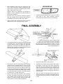
FINAL ASSEMBLY
USING A SHARP BLADE, STRIP COVERING FROM
STAB, FIN, & FUSE WHERE THEY MATE, FOR WOOD
TO WOOD GLUE JOINT. LEAVE 1/8" TO 3/16" OF COVERING FIRMLY ATTACHED TO CENTER PLATFORM. CAUTION:
WHEN TRIMMING COVERING, AVOID CUTTING INTO WOOD
STRUCTURE UNDERNEATH.
The top edge around the cabin area should be lined all
around with 1/16" x 1/4" self-adhesive foam wing seating tape. When the wing is in place, the tape seals
against entry of exhaust oil and dirt into the radio compartment. Also, the tape is a cushion between wing and
fuse to prevent abrasion of the covering.
Glue 5/16" triangle stock on side of the tin.
Mount wing on the fuse using rubber bands. Measure
To provide a firm wood-to-wood glue joint, strip covering
carefully from the fuselage sides out to the wing tips
(arrows 'A') to be sure that the wing is centered. Then
measure from the wing tips to the back end of the fuse
(arrows 'B') to make sure wing is square with fuse. Mark
the wing center at leading and trailing edges, and the
fuse, with matching line-up points. Color-Stripe tape can
be used for this, or certain marking pens.
from bottom of stab center where stab contacts fuse
(see sketch A) avoid cutting structure underneath. Be
certain to leave enough covering firmly bonded to stab
center (minimum 1/8" to 3/16"). Likewise, if slab area on
fuse was covered, remove covering. Glue stab firmly to
fuse and let dry.
Trial fit fin in place on fuse/stab (arrow 'D'). Strip cover-
Using no glue, trial fit stab in place on fuse, marking it
ing from fin bottom (if covered) and respective area on
fuse/stab. Glue fin firmly in place, and square with stab.
Let dry.
for center, and adjust as necessary to line up with wing.
Then measure from the stab tips to the fuse front
(arrows 'C') to make sure stab is square with fuse. Mark
match-up lines on fuse and stab for alignment.
41
Insert formed wire maingear struts in fuse. Position
nylon landing gear straps; then mark, drill, and mount
with #2 x 5/16" screws (see sketches above and illustration on page 10).
Press one of the four steel collars into the pocket in the
nylon steering arm (side holes must be aligned). Thread
#6-32 x 3/16" socket head screw in a few turns.
Install nosegear strut in bearing and steering arm (refer
to illustration on page 10). Tighten socket head screw
with Alien wrench.
Install wheels on axles as shown: eyelet first, wheel,
then wheel collar and set screw.
FUEL SYSTEM
Assemble your fuel tank per manufacturer's instructions.
Refer to full size views on plan, and install fuel tank and
lines. Support bottom of tank with foam rubber.
Attach the fuel line (leading from the "clunk" weight
inside the tank) to your engine's carburetor. This is also
the line to use for fueling. You simply slip the line off the
engine, fill the tank, and re-connect line to engine.
OPTIONAL PRESSURE FEED
If your muffler has a fuel-line type fitting on it, you can
use it to "pressure feed" fuel to the engine for smoother
and more reliable running, In this case, the vent line is
connected to the muffler fitting.
42
TREAT YOUR RADIO RIGHT - AND IT WILL DO THE SAME FOR YOU!
by Hal deBolt
Famous R/C Pioneer
Today's RC systems are very well engineered and constructed.
However, they will remain only as good as the way in which they
are USED. Experience has shown us how to use them to perfection. Follow the proper rules religiously, and anyone can have
success.
CONNECTORS: In using connectors, never pull on the wires
to disconnect; grasp the plugs instead. Clean them by dunking
in solvent; dope thinner is fine. Do tape the connectors together
when Installing, and be sure that there Is no strain
on the cables.
RECEIVERS: Receivers must be vibration free. Wrap them in a
minimum of 1/2" soft foam rubber (not plastic foam) when
installing. Keep clear of all cables and batteries. Tune annually
as indicated below under "Check-Ups."
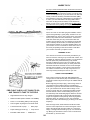
RECEIVER ANTENNA: The receiver antenna must be routed
directly out of the airplane and to the top of the fin, or preferably
to the stabilizer tip. At no place should it be close to anything
metal or electronic. Visualize it as being about 3" In diameter
instead of 1/16". Do not allow anything other than wood or plastic to be within the 3" diameter.
SERVOS: Servos are vibration prone. Do mount them with
grommet shock mounts in servo trays which are in turn shock
mounted. Keep them clean. If a neutral position should drift, it is
a sign of a change; find out WHY before flying again.
TRANSMITTERS: Keep your transmitter clean and free from
fuel residue and dirt. Battery condition and RF output should be
monitored, and the system should be aligned and tuned annually. Do not transport under vibration (floor of a car); place them
on something soft.
PUSHRODS: Obviously, pushrods should be Installed freely
so that they place no load on the servo. Using a servo's power
to move a tight rod or heavy surface by force increases the battery drain, shortens the electronic life, and can cause neutralizing problems. While being free, the pushrod must not flex or
vibrate. Any vibration is transferred directly to the servo, its gear,
motor and pot. While maintaining freedom, flexing and vibration
can be prevented by the use of guides and fairleads on the
rods.
CHECK-UPS: When—at least once annually, and it should
include the tuning and alignment of the system, plus TESTING
the batteries. Also, any time anything unusual occurs during
usage. A malfunction or "glitch" is the first sign of an impending
failure; it should not be ignored. Where—at a factory authorized
center that understands your particular equipment. If not available, an established center can offer advice.
AND: ADD A SMALL PORTION OF GOOD LUCK.
43
RADIO PREPARATION & INSTALLATION
Set RC airborne equipment temporarily in fuse (refer to
1. Before continuing, make sure each of the following items
has been completed:
plan for approximate location).
a) Battery most forward.
b) Receiver (Rx) next.
c) Servos rearmost.
d) For "A" or 'B" wing, install aileron servo in
wing.
Model is fully covered and painted wherever necessary.
Control surfaces are hinged in place.
Tail assembly is glued solidly to fuselage.
Engine is fully installed, with spinner and prop in place.
Muffler is installed.
Fuel tank is installed, with foam rubber supports to hold it
Refer to fuse side view on plan for "BALANCE RANGE,"
then measure and mark this range at top of cabin sides.
level.
Stab and rudder pushrods are complete (rear end only).
Landing gear and wheels are installed
Temporarily rubber band wing in place on top of fuse.
When flying, use at least seven #64 rubber bands on
each side.
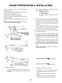
Lift the model under the wing near the fuse by finger
tips. A better way is to use a simple set-up with a couple
of 1/4" dowels with rounded tops, spaced 5" apart.
a)
Move finger tips or balance stand through the balance
range until model is level.
b)
If you need to support the model outside the balance
range to get it level, remove wing and shift R/C equipment away from heavy end of model until model will balance within the range. The preferred location is at the
wing spar.
c)
if shifting the R/C gear still doesn't balance the model,
add weight to extreme nose or tail respectively until it's
right. The least weight is needed when added as far forward or back as possible. Fasten weight permanently in
place.
Carefully remove the wing, and mark on fuse interior the
locations of all R/C parts.
2. Balancing The Model.
Completing stab and rudder pushrods:
Tape stab and rudder pushrods to side of fuse with rear
a) Measure about 2" from the backsides of the servos
to the balsa pushrods, and mark them at this
point.
b) Remove pushrods from fuse, and cut them at
marks.
c) Cut one 1/16" x 12" wire in half, and use these
pieces to complete forward end of pushrods.
ends in approximate final position (refer to full size view
on plan).
44
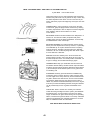
3. Radio Installation.
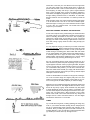
YOUR TRANSMITTER (Tx) IS BUILT LIKE ONE OF THOSE
SHOWN HERE. EACH SKETCH SHOWS HOW THE
STICKS ARE MOVED TO CONTROL VARIOUS PARTS OF
THE MODEL.
A.
Read and follow the instructions that came with your
radio.
B.
If your batteries are dry cells, they should be fresh. If
rechargeable nicads, they should be fully charged,
C.
Hook-up Radio and Try Operation.
Refer to "Transmitter Function Sketch" below, and
observe which servo wheels move when stick is moved
for various controls.
FOR "A" or "B" WING (With Ailerons)
USED WITH "C WING ONLY (Non-Aileron)
Apply tape (which you can write on) to each servo.
Identify each servo for its control function. Mark the plug
to each servo the same way: "R" for rudder, "E" for elevator, "T" for throttle, "A" for ailerons if you have them. If
your receiver doesn't have separate plugs for each
servo, but places for the servos to plug in, apply a piece
of tape nearby that you can mark for each application.
THE INSTALLATION ILLUSTRATED HERE IS A GUIDE:
DEPENDING ON YOUR ENGINE AND R/C GEAR, YOU
MAY NOT BE ABLE TO FOLLOW IT EXACTLY.
READ THE INSTRUCTIONS THAT CAME WITH YOUR
RADIO THOROUGHLY BEFORE STARTING RADIO
INSTALLATION.
45
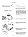
4. Servo Arrangement.
With throttle servo at forward position, place servo so
output wheel is on same side as engine throttle arm.
Rudder servo should be on side opposite to throttle
servo so it can drive the nosegear steering arm in a
nearly straight line.
"REVERSE" SERVO CAN BE IDENTIFIED BY A
DOT IN MOUNTING FLANGE AS SHOWN HERE, OR
A DIFFERENT COLOR CASE OR MARKINGS.
In radio sets without "servo reversing" feature, the rudder servo is usually a "reverse" servo. A "reverse" servo
can be identified by a dot, or a different color case or
markings.
Elevator servo occupies remaining rear position.
5.
Servo Movements
As mentioned in the introduction on page 2, radio systems with "servo reversing" simplify radio installation.
With a regular non-reversing system, you must match
each pushrod to its corresponding servo's rotation. With
"servo reversing," pushrods can be hooked up to either
side of the servo s output wheel, and after checking the
control response, a servo responding in the wrong direction is easily, switched to correct action (see your radio
manufacturers instructions).
CONTROL MOVEMENTS ARE THE SAME
AS IN A FULL-SIZE AIRPLANE
The 2+1 arrangement on the plan shows standard servo
placement for a "servo reversible" system. For either
type of radio system, check your equipment out with the
following procedure.
Push the transmitter (Tx) throttle lever up away from you,
and observe where throttle servo wheel should connect
to the throttle pushrod to give full throttle, Mark this on
the servo wheel (write on tape). Return throttle lever to
full down (idle position).
Ailerons ("A" or "B" wing). Move the aileron stick to the
right, and observe that the right aileron must be connected so it moves up.
Move the elevator stick up, and observe where the elevator pushrod must be attached to the elevator servo to
pull the elevator down. Mark servo.
Move rudder stick to the right, and observe where rudder
servo wheel should connect to give right rudder and
nosegear steering. Mark this on the servo wheel.
Remember, for non-reversing radios, that the rudder
servo usually needs to be a "reverse" servo.
46
6.
Mounting The Control Horns and Pushrods. Rudder Horn
(Small):
Refer to fuse side view on plan for correct location.
Tack-cement small horn on correct side of rudder.
Drill through holes in horn, and mount nut plate on other
side using screws as shown. Trim screws flush with nut
plate.
Remove covering from die-cut hole in fuse top (adjacent
to dorsal fin) for rudder pushrod.
Lay pushrod over pushrod views on plan, and make
bends as required. Working from cabin, feed rudder
pushrod (threaded end) through fuse rear and out exit
hole. Use a loop of string or wire to pull threaded end up
through exit hole.
Twist mini-snap (clevis) onto threaded rod, Hold pushrod
wire with pliers while installing mini-snap. Connect to
rudder horn.
ELEVATOR HORN (Large):
Insert threaded end of elevator pushrod from cabin
through fuse rear and out slot opening about 2".
Install mini-snap on rod, and connect to elevator horn.
Position horn under elevator — refer to plan for correct
location, When horn is centered so mini-snap moves in
and out of tail opening without scraping sides, mount
horn on elevator.
47
7. Mounting Servos
Tape front end of rudder and elevator push rods up out
of the way under cabin top doublers.
Glue two ply braces to bottom of ply servo tray as
shown.
Insert the soft rubber gram mete into the mounting holes
of your servos and tray.
Correctly position servos in tray, Mark through the grommets for the location of the mounting screws. Remove
the servos. With a 1/16" drill bit, drill holes in tray.
Reinstall servos and gently fasten them in place with
screws provided with your radio system (or with #2 x
3/8" sheet metal screws).
Engage tab at rear of servo tray into matching side
notches in former "C".
Position 7/16" x 3-9/16" ply mounting rail under front of
servo tray so rail is about 1-1/2" above fuse floor. If the
rail is too long to fit inside fuse, sand one end until it fits
snug. Glue rail to fuse sides.
Glue servo tray to rail and former "C".
48
8.
Installing The Throttle Pushrod.
Screw mini-snap on the extra-long remaining threaded rod.
Carefully bend rod to fit curve of throttle pushrod as shown in fuse
top view on plan.
Cut a 10½" throttle pushrod guide tube from long nylon tube
(remainder is steering pushrod guide tube).
Starting at hole in firewall, slide throttle guide tube into fuse and
through upper side slot in former B, Nylon guide tube should protrude 1/8" out firewall as shown in sketch below, Slide rod through
guide tube and connect mini-snap to engine throttle arm.
At rear end, make sure bend in wire leads it towards throttle servo
wheel as shown on plan.
Move pushrod back and forth to simulate servo action. The pushrod
should move freely; if not, adjust wire where necessary. Feel the front and
rear "limits" of the throttle arm. Later, when setting controls, be sure to set
the throttle servo linkage within the range of throttle arm movement, Glue
guide tube to firewall, former B and fuse side. If the guide tube needs support, make a "stand-off" from 1/4" scrap balsa (see plan), Tailor the standoff to suit the curvature of your installation, glue it only as required so it
doesn't interfere with pushrod sliding action.
Remove servo wheel, and install the CG Pushrod Connector as
shown. This device lets you easily adjust throttle pushrod movement. Remount servo wheel.
Make sure throttle servo is at idle position. Engine throttle arm also should
be at rear or idle position. Align and cut the pushrod wire so it extends
1/4" to the rear of the pushrod connector, and attach. Check action with
radio, and if OK, throttle pushrod hookup is completed.
9. Installing The Nosegear Steering Pushrod.
Make a square bend down 1/4" from one end of 1/16" x 16-3/4"
wire, and a slight upward bend 1" further back as shown on plan
side view. Slide steering guide tube over wire, and insert unbent
end of wire through hole in firewall, lower side slot in former B,
and back towards the rudder servo. Slip bent end into outermost
hole in steering arm. Guide tube should remain about 3/4" behind
firewall.
Bend the wire towards proper hole in rudder servo wheel but DO
NOT CUT YET! Move pushrod to check for free movement; correct as necessary. Glue guide tube to former B and fuse side.
With nosewheel pointing dead straight ahead, the end of the
steering arm should be 1/4" - 5/16" away from the firewall. Back
at the servo, allow additional 3/8" past servo wheel hole, and cut
it there. Bend cut end up 1/4".
Roughen 1/4" bent end with sandpaper for better grip of snap-nut.
Remove servo wheel to insert pushrod, add snap-nut, and then
remount. Check action with radio. This completes the nosegear
pushrod hookup, Later, during taxi tests, you can adjust nose
wheel steering by loosening steering arm socket head screw.
10a. Hooking Up Elevator and Rudder Pushrods.
49
Position elevator pushrod so that the T.E. elevator is centered
with stab, Allow additional 5/16" past servo wheel hole, then cut
and bend forward end of pushrod, Roughen bend-up wire with
sandpaper, remove servo wheel and insert wire, and retain with
snap-nut.
Position rudder pushrod so that the rudder is aligned with fin. Cut
and bend forward end of pushrod as above, and attach to rudder
servo wheel.
10b. Hooking Up Aileron Pushrods ("A" or "B" Wing Only).
Re-install aileron servo in wing. Tape ailerons in neutral position
(so flat bottom of wing and ailerons are flush).
Install horn brackets on aileron horns as shown. Install minisnaps on each 7" True 1/16" threaded rod, then connect minisnaps to horn brackets. Align each rod to its respective hole inservo wheel. Allow additional 5/16" past servo wheel holes,
then cut and bend forward end of pushrods, same as elevator
pushrod procedure.
11. Installing Switch and Charging Jack.
Temporarily set battery and Rx in fuse. Position switch and
charging jack cover plates on outside of fuse on side opposite
to engine exhaust, and where they will not obstruct the battery
or Rx, Mark through cover plates (or holes and openings.
Remove battery and Rx.
Make holes through fuse side Make sure hole for switch button
is long enough for it to move to ON and OFF positions.
Install switch and jack.
Later, when radio is operating, identify ON and OFF positions
with decals provided. Preferred "ON" position is forward.
12. Battery Pack.
You must have fully charged nicads or fresh dry cells for flying.
Wrap battery in 1/2" very soft foam rubber to cushion it from
vibration and shock. Use rubber bands or tape to hold the foam
around the battery. It is also good to place battery and Rx in
individual plastic bags to protect against fuel and oil.
Position battery in fuse, and hold in place with additional foam
rubber
13. Receiver (Rx).
Do not cut the antenna wire attached to the Rx.
Wrap Rx carefully in foam like the battery.
Re-connect all cables so R/C system is operational; be sure
that each servo is plugged into its respective Rx terminal.
Place Rx in fuse behind the battery.
Lead the antenna wire up and back along cabin top doubler and
out top rear of cabin. Tape wire inside cabin.
Using clip supplied with radio, suspend antenna from top of fin
as shown above. Adjust antenna in clip so it is just slightly taut,
not tight. Let excess wire hang loose from clip.
Gather all excess cables together behind Rx, and hold them
down with foam.
Apply "ON/OFF" decals to outside of fuse to identify switch
positions.
All pushrods must move freely, without binding; adjust if required for
smooth operation. When setting control travel, be cautious that no servo
is hooked to a control in a manner that prevents the servo wheel from
moving through its complete range of rotation, For example, if the throttle servo "buzzes" when moved to "full-throttle" position, the servo still
has movement left, but is jammed against the engine's full-throttle limit
position, This can damage the servo and drain the battery, leading to
loss of control, and a crash.
50
14. Setting Control Surfaces.
CUT GAUGES FROM PLAN
All pushrods must move freely, without binding; adjust il required for
smooth operation. When selling control travel, be cautious that no servo
is hooked to a control in a manner that prevents the servo wheel from
moving through its complete range of rotation. For example, if the throttle
servo "buzzes" when moved to "full-throttle" position, the servo still has
movement left, but is jammed against the engine's full-throttle limit position. This can damage the servo and drain the battery, leading to loss of
control, and a crash.
Move throttle lever on Tx to cycle the throttle from idle
The following instructions describe how to set the control surfaces measuring up and down movement using the angle templates provided. For
first flights, it is recommended that you set controls per the angle templates for "softer" control response. Later, after you are more familiar with
the airplane, you can always increase the throws as you prefer.
With elevator trim tab on Tx set in center, adjust elevator MintSnap until elevator TE. is centered with stab as shown.
Move the elevator stick on Tx full up and down. The elevator
should move to match template angles, up and down.
With rudder trim tab on Tx set in center, adjust Mini-Snap until
rudder TE. is centered with fin. Nose wheel should point straight
ahead.
Move the rudder stick on Tx full right and left. The rudder should
move to match the rudder template angle, left & right. The nosewheel should move only very slightly as it doesn't take much to
steer on the ground.
With aileron trim tab on Tx set in center, adjust and connect
mini-snaps until ailerons are neutral with wing. Move the aileron
stick full right and left. The ailerons should move respectively up
and down to match aileron template.
THIS COMPLETES THE RADIO INSTALLATION
PILOT INSTALLATION
Cut 1/4" off one end of one 1/8" ply pilot platform support (PPS).
Then glue two of them together as shown.
Drill 1/16" diameter holes through pilot platform and PS at
marked locations.
Using a #2 x 5/16" sheet metal screw, join platform to support.
2.
Fit platform assembly inside cabin, engaging platform front with
notches in sides of former B, Adjust platform rear so it is about
horizontal. Carefully sand off end of PS if necessary for good fit
Glue PS firmly to fuse sides. Parts may be painted to match
fuse interior.
3.
Cut pilot halves apart at bottom, and trim off scrap. Rub each
half gently over fine sandpaper to smooth edges for joining.
Carefully align front and back and hold together with tape. Apply
dabs of glue at joint, remove tapes and complete gluing.
4.
Paint pilot figure as desired, flesh, hair and jacket colors are
your choice. Artist's acrylics and modeler's enamel paints are
available in many colors — no mixing required. Warning: do not
use lacquer based paints — they will destroy the plastic. When
painting face, leave eyes white, then later carefully add eye
details with a fine brush or toothpick. When dry, glue pilot in
place on platform.
1.
By special arrangement with Williams Brothers, a pilot figure
is included with your kit. When installed, it adds a final touch
of realism. The next few steps show how to assemble and
mount this pilot in your model. Also, the pilot platform holds
the battery and receiver in place.
51
SETTING UP YOUR ENGINE
Do not attempt to fly your model until the engine runs dependably.
It should idle without stopping and the transition through alt
engine speeds should be smooth.
WARNING! The turning propeller can cause serious injury, such
as deep cuts. Never reach across the propeller! Avoid wearing
loose clothing (such as neckties) or jewelry which could fall into
the spinning propeller, Small children should not be allowed near
a running engine for these reasons. No one (including spectators)
should stand in line with the propeller-a broken propeller blade
becomes a bullet and could seriously hurt someone.
There are four basic adjustments to make your engine run well.
Compare your engine's carburetor to the sketch at left and locate
the four parts below.
1.
Throttle "barrel" opening. The rotating cylinder inside the
carburetor is called the throttle "barrel". It has a hole In
the middle to admit air. By rotating the barrel, the throttle can be "wide open" or completely "closed." This controls engine speed.
2.
Idle Low-Speed Stop-Screw. This screw allows you to
set how much the barrel can close for idle (to fully
closed-engine stop).
3.
High Speed Mixture (also called the Needle Valve) controls the mixture of fuel & air at high engine speeds.
4.
Low Speed Mixture (controls fuel/air mixture at Idle
speeds)
Now that you know where these parts are, let's make the adjustments one-at-a-time. There are four basic steps to make your
engine run well.
SETTING THROTTLE (engine not running).
Start with transmitter throttle stick full open and trim full high.
Then move throttle stick full low (with trim high) 1/8" throttle
opening should show. Moving trim full down should fully close
the barrel. If any adjustment is needed for proper range of throttle movement, determine best combination of hole positions for
the servo wheel and throttle arm.
ADJUST IDLE/CUT OFF.
We recommend you adjust idle stop screw to just allow throttle
to fully close, this will allow you to shut off the engine on command when throttle trim is moved full down.
HIGH SPEED MIXTURE ADJUSTMENT.
Temperature, humidity, fuel blend, etc. are variables that effect
mixture. You should always start adjusting by setting high speed
needle valve first, approximately three turns, then go back to
idle. Adjust gradually, going back and forth until a good general
setting is made. Once an engine is properly set, you should not
have to touch the carb except for a click or two on high speed
(needle valve) fine tuning.
52
FIRST START ENGINE.
SLOW SPEED MIXTURE ADJUSTMENT
To start engine, first open 1/8 to 1/4 throttle. Prime with 4-6
drops of fuel in carb, attach glow plug and flip prop counterclockwise to start. Or use an electric starter that will spin the
prop.
Now reduce engine throttle to idle speed. If it will idle, wait for
10 seconds and hit full throttle.
—If it speeds up very quick and dies-it's too lean.
—If it sputters, hesitates and dies-it is too rich.
WHEN ENGINE FIRES.
Your final idle adjustment should be a bit on the lean side to
give the best transition. Once set it may never be adjusted
again.
—If it speeds up and dies it is too lean. Turn high speed (needle
valve) 1/2 turn out (add more fuel).
—If it sputters, spitting raw fuel out the exhaust and dies—it's
too rich. Turn high speed needle valve 1/2 turn in (reduce fuel).
If engine will not run at idle, open throttle up to 1/3rd and try to
determine if it's rich (sputtering) or lean (dies quickly) and adjust
slow speed screw. Then slow engine lower and re-adjust, if necessary. A good sport 2-cycle should idle 2,500 RPM easily
Some engines will go to 2,000 but that's very low.
Continue to adjust until it will run continuously (it should run on
the rich side).
Hint: if you pinch the fuel supply line shut, the engine RPM
should increase slightly before it dies—this is the correct High
Speed Needle setting.
GENERAL. Do not fly your plane until engine is set up properly
As engine "breaks-in," both idle and power will improve. Bad
idle can be caused by dirt, bad fuel, or a bad glo-plug. Hint; if at
idle the engine dies when you remove battery power from plug,
it's probably too rich or a bad plug.
Now slowly open the throttle fully and again adjust needle valve
not to peak power but a bit less on the rich side. High speed is
set.
Use the most forward balance point recommended for the first flights of any new
model, and for flight training. Balanced
here the model will be "easier" to fly.
Use the most rearward balance point for those experienced in sport
and aerobatic flying. The model will be more responsive to elevator
control. As balance is moved rearward, more pilot skill will be required.
WARNING! If you try to fly a plane with the balance point further
behind the rear of the recommended range, you run the risk of having
an unstable aircraft and there will be a stranger likelihood of crashing.
53
WHERE TO FLY
Fly only in areas sanctioned for R/C and known to be free of
radio interference. Ask your hobby dealer or other modelers
if there is an R/C flying field that is used by a local R/C club.
This is the ideal place to fly. If you don't know of an R/C club
nearby, contact the Academy of Model Aeronautics (AMA),
at the address on the front of this booklet, for information on
a club in your area. Remember: R/C flying fields need to
have rules to help prevent accidents, so ask about them
before you turn on any of your equipment! DO NOT TEST
your transmitter in the parking lot or anywhere nearby until
you are sure no one else is using your radio frequency. This
could cause another flyer to crash and make you very
unpopular!
If there is no club or other R/C flying site available, locate a
square area (preferably a grassy field), at least four or five
football fields long, which is free of power lines, trees, poles,
houses, busy streets and other obstructions. It must be at
least three miles away from any areas where other R/C
models, such as boats or cars, are operated, It should also
have a relatively smooth surface, as it will take practice to
learn precision landings, If you find a suitable location, turn
your receiver on for 2 or 3 minutes to check that no one in
the vicinity is operating an R/C device which could affect
your receiver and cause your plane to crash.
LEARNING TO FLY
Your chances of success are enormously increased if you
have an instructor. Learning to fly is harder than it looks, and
a mistake can seriously damage or destroy your model Even
full-scale pilots have problems learning to fly models
because it's different—they're not in the cockpit It's worth
real effort to find someone to teach you. Many clubs have
authorized instructors and there are even some R/C flight
schools. Ask your dealer, or even check on the internet to
see if there is someone who can help. Only if there is no
other way should you attempt to learn on your own.
CHECK YOUR EQUIPMENT!
Prior to going to the flying field, with radio batteries fully
charged, turn on both receiver (Rx) and transmitter (Tx) and
actuate all controls many times until you are satisfied with all
functions.
Before beginning each day's flying, make a range check of
your equipment in accordance with the manufacturer's
instructions, in general, with transmitter antenna collapsed to
6"-8", you should have an at least 100 foot range on the
ground. To check this, turn on both the transmitter and the
receiver switches, set the model heading away from you,
and walk away while transmitting signals. Watch to see that
no signals are missed until you are at least 100 feet away.
Only if the equipment works perfectly should any flights be
attempted. Again, be careful to not use your transmitter
when anyone else at the field is flying or testing on the same
frequency!
PRE-FLIGHT CHECK LIST, THINGS TO DO,
AND THINGS TO TAKE TO THE FIELD
Flight batteries fresh or fully charged
Radio transmitter (DON'T LEAVE IT AT HOME!)
Fresh 1-1/2 volt starting battery & Glo plug clip
Tools to tighten anything that can vibrate loose
Fuel and fuel bulb or pump
Paper toweling (for clean up) Prop wrench
Extra #64 rubber bands SUPER JET
After the range check, stand behind the model and make
sure the control responses are correct. Moving the control
stick to the right should give right rudder (on a 3-channel
setup) or the right aileron should go up (on a 4-channel setup). Moving the stick back or down on the Tx should move
the elevator up, and vice versa.
Extra props
54
Check also to see that your nose wheel turns to the right when
you give right rudder. Your throttle should open to permit full
power when the stick or tab is moved forward or up. Make sure
that everything is neatly and firmly in place—engine fastened
down, servos snugged down, receiver and battery wrapped in
foam rubber, tank properly supported, etc. Prop and spinner must
be tight. Nothing should be loose, or unfinished, or unchecked.
Receiver antenna must be extended, not coiled up inside the
model.
With everything ready, the engine should be started and broken
in for at least a tank or two at no more than moderate speed.
While the engine is running, the control surfaces should not jitter
or move until you command them. The throttle also should
respond to your command.
PRACTICE STEERING THE MODEL ON THE GROUND
For the next couple of hours, practice taxiing the model around at
low speed. This is a very helpful step in making you feel more at
ease in controlling the model. Do not rush it. Use a parking lot
rather than a street where you are likely to run into a curb and
damage your model. Practice taxiing in light breezes or when the
air is calm; strong or gusty winds can catch a wing and flip your
plane over.
It is very important in flying to make all your control movements
slow and measured. Rapid movements tend to throw the model
out of control. Apply minimum throttle so that it just keeps the
model moving at a walking pace. With rudder stick and rudder
trim in neutral position, the model should move straight ahead, if
it constantly turns left or right, the nose wheel is not pointing
straight ahead, and should be adjusted until i1 is correct. Adjust
the nose wheel only, loosening the steering arm to do so.
Do a lot of practicing with the mode! coming towards you, as it
often will in the sky. When the plane is pointing at you, the steering will appear "reversed." When you give right rudder, the plane
turns to your left—but the model actually is turning to its right as
you commanded. With practice, you will soon overcome this.
When the model comes towards you, simply push the stick left or
right towards whichever way the ship is turning. Another helpful
technique is shown in sketch A.
"Head-on" disorientallon is a nuisance on the ground, but dangerous in the air where things can happen pretty fast. The more
familiar you become with the behavior of the model as you control it on the ground, the better prepared you will be for flying.
After taxi runs are completed, thoroughly examine the model, and
tighten loose screws, etc. First flights should be made on a day
that is not very windy or gusty. There should be very few people
or other distractions around. You will need to concentrate. Your
success doesn't depend on following the instructions here to perfection, but you should have a flight sequence in mind. Think
ahead of the model—don't chase it around the sky always one
thought and one control command behind it. Your first flights
should last no more than 2 or 3 minutes.
TURNS
Try to make all turns gentle, not tilting (banking) the wings very
much. If you increase the bank (making the turn steeper) there
will be a corresponding weight increase and reduction of lift.
Therefore, when you bank your plane it will start to descend. To
maintain altitude in a turn you will have to add enough back stick
(up elevator) to hold the nose "up" through the turn.
55
FIRST FLIGHTS
INTRODUCTION
There is no way to fully explain the principals of flight and the techniques of flying in only a few pages. Entire books have been written
about apparently simple subjects as the shape of the wing. And
even if you read several books about flying techniques, there is no
substitute for an experienced R/C flyer helping you learn to actually fly, The following information is not intended to replace your flight
instructor but we hope it will help you understand basic flight concepts and techniques.
One of the most important yet sometimes neglected pre-flight
checks is to always make sure the wing is securely banded to the
fuse! Use at least seven #64 rubber bands on each side of the wing.
The first flight instructions below show the essential flight elements.
If you have a helper, acquaint him with these steps, and have him
call each of them off to you at the appropriate time.
NOW THAT YOU'RE READY...
Turn on the Tx and Rx and make sure all control surfaces are
responding correctly. See that the Tx trim tabs are centered with
the surfaces centered and make sure you have a reliable idle and
correct High Speed Needle Valve setting and that the Tx meter
registers in the "safe" zone.
2. Be patient, let the model climb slowly to about 150-200 feet of
altitude, add just a touch of left (or right aileron) stick pressure
until the model begins a very shallow turn in the direction you
want to go.
3. Try to maintain this shallow turn. Do not let the turn get too
steep (see previous page). The wind will tend to blow your plane
further downwind-try to keep it flying upwind at all times prior to
your landing approach. It is more difficult to fly a model when it is
downwind, and if a mistake is made the model will end up further
downwind, making it more difficult to fly back to the field,
It is important to have a total flight plan in mind. Look at the flying sketches here to get an idea of the take-off direction and
space you will need when flying from your field.
1. Start your engine. Point the model directly into the wind.
Advance the throttle smoothly, steering on the ground with rudder the plane will gain speed rapidly. After it rolls about 100 feet,
add slight back stick (up elevator) pressure so the model rises
smoothly from the ground. With ailerons keep the wings level.
Hold only as much back stick as necessary to keep the plane in
a 5' to 10' gentle climb (if you climb too steeply the model may
slow down and then "stall" and fall to the ground).
To compensate for wind, you should continue making your
upwind turns shallow, but make your turns flying with the wind
(downwind), a little steeper.
56
OVERSTRESSING THE AIRFRAME, Even world class aerobatic competition planes tan be overstressed. The Mirage is very
strong but can be broken in flight by over-speeding and then jerking the controls. If you find yourself In a steep high-speed dive,
immediately switch motor off, level the wings and gently pull the
stick back (add up elevator) to recover.
SPIRALS. As explained before, as you increase bank angle, you
have to add back-stick (or "up") to keep flying level. And if you
make the bank too steep, you will have to add more back-stick to
hold the plane level. But it won't keep up. it will start to spiral downward—increasing its speed. Trying to "pull" the model out of the
spiral by pulling back on the elevator only makes things worse!
This sequence of events happens fast and can panic new flyers to
the point that they fly the model right into the ground!
TO GET OUT OF THE SPIRAL-1st LEVEL THE WINGS! Then
2nd, pull it smoothly out of the dive.
STALLS. Your model's movement through the air keeps it
flying. If you fly too slow,there is a point where it will stop
flying and fall out of the sky. This is called a stall. The
Mirage has very gentle stall characteristics. However, when
landing, be careful not to slow down too much.
For your first landings, don't be concerned about the model
landing on the runway. All you want is that the model land safely. With
practice, you'll be able to land where you want. If you can confidently fly the model in wide circles as shown in the illustrations and then
simply reduce throttle and glide straight into the wind for your first
landings, well that's fine.
LANDING APPROACH
At most flying fields you will see models flying a rectangular path
around the runway-this is called the "pattern," The most important
reason for flying the pattern is that as the model flies at different
directions in the wind, you will be better prepared for the conditions
as you land. Full-size aircraft fly a landing pattern for this same reason. Another important reason for flying the pattern is to organize the
take-off and landing traffic, reducing confusion.
The "traffic" pattern consists of: PATTERN ENTRY, DOWNWIND
LEG, BASE LEG, then FINAL APPROACH & LANDING. And remember, "a good approach is a good landing."
4. PATTERN ENTRY. Plan to enter the pattern upwind at about 150
feet of altitude.
5. DOWNWIND LEG. Make the downwind leg far enough away to
allow for gentle turns to Base Leg and Final Approach You do not
want to make tight "panic" turns when landing. Reduce throttle 1/3rd
to begin a slow descent When the model is about 45° downwind of
the landing area turn to Base Leg.
6. BASE LEG. Continue your descent, letting the model slowly lose
more altitude by reducing throttle to high idle.
7. FINAL APPROACH & LANDING. Make a gentle turn to point the
model in the direction of the landing area. Reduce throttle to idle.
Keep nose of plane slightly down so you don't stall. Steer the plane
into the wind as it glides keeping the wings level. Let it settle in
towards the ground and land. Just before the model lands you can
add a touch of back-stick (up elevator) to "flare" and soften the landing.
Walk over to your plane, stop the engine. Turn off the receiver first,
then the transmitter. Stop shaking, congratulations!
So many Tigers, so little time.
THE TIGER 2 / TIGER 2 ARF
WINGSPAN:
WING AREA:
FLYING WEIGHT:
POWER:
61"
680 SQ."
4.75-5.25 LBS.
.40-.46 2-CYCLE
.48 4-CYCLE
Tiger 2 Kit: $99.99 (Street Price)
Tiger 2 ARF: $159.99 (Street Price)
Kit includes complete hardware package and canopy.
ARF also includes nylon engine mount, wheels, spinner and fuel
tank. Tail-dragger accessories not included.
WINGSPAN:
WING AREA:
FLYING WEIGHT:
POWER:
70"
855 SQ."
6.5-7.5 LBS.
.45-.65 2-CYCLE
.65-.80 4-CYCLE
Tiger 60 Kit: $109.99 (Street Price)
Tiger 60 ARF: $209.99 (Street Price)
Kit includes complete hardware package and canopy.
ARF also includes nylon engine mount, wheels,
spinner and fuel tank.
Tail-dragger accessories not included.
You know the planes – some of the
best intermediate flyers in anyone’s
hangar. Gentle as a kitten when you want
them to be, but plenty of growl when you
turn them loose. Fun flying was never any
better.
Whether you prefer to build them
yourself, or the convience of a 90% prebuilt ARF, our Tigers are terrific everyday
sport planes for RCers who aren’t looking
for a challenge every time they head for
the flying field.
hands of experienced fliers. Loops and
rolls are clean and precise and inverted
flight couldn’t be easier or more stable.
THE TIGER 60
THE PERFECT SPORT FLYER
When you’re ready to step up, our
Tiger 60 will give you the added
performance that only a larger model
can give.
THE TIGER 2
A LOW WING TRAINER
With its light wing loading, low landing
speed, and tricycle gear, the Tiger 2 is hard to
top as a low wing trainer.
Yet those same features - along with
long tail moment, shallow dihedral, and
clean symmetrical airfoil, make for supersmooth aerobatic performance in the
When you’ve outgrown the tri-gear, all of our
Tigers easily convert into a tail-dragger configuration.
Like other Goldberg kits, our Tigers
feature top-quality American-made
hardware. All major components are of
finest balsa and light ply.
Our ARF versions are pre-covered with
iron-on film. Then we’ve pre-assembled
the elevator, installed pushrod guide tubes,
included a black cockpit insert, and put in
wing guide tubes for quick, easy
installation of aileron servo wires.
Both versions include a complete
hardware package and our fullyillustrated, step-by-step instruction
booklet will have you out at the
field in record time.
Get a Tiger now at your local hobby
retailer, and you’ll have it jumping
through hoops in no time.
CARL GOLDBERG
PRODUCTS LTD.
The Tiger 2, Tiger 2 ARF, Tiger 60 & Tiger 60 ARF.
Only from Carl Goldberg Products.
PO Box 818, Oakwood GA 30566
Info: 678-450-0085 Fax: 770-532-2163
58
www.carlgoldbergproducts.com
© 2002, Carl Goldberg Products, Inc.
THE TIGER 60 / TIGER 60 ARF