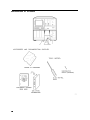
1
About this Manual
We’ve added this manual to the Agilent website in an effort to help you support
your product. This manual is the best copy we could find; it may be incomplete
or contain dated information. If we find a more recent copy in the future, we will
add it to the Agilent website.
Support for Your Product
Agilent no longer sells or supports this product. Our service centers may be able
to perform calibration if no repair parts are needed, but no other support from
Agilent is available. You will find any other available product information on the
Agilent Test & Measurement website, www.tm.agilent.com.
HP References in this Manual
This manual may contain references to HP or Hewlett-Packard. Please note that
Hewlett-Packard's former test and measurement, semiconductor products and
chemical analysis businesses are now part of Agilent Technologies. We have
made no changes to this manual copy. In other documentation, to reduce
potential confusion, the only change to product numbers and names has been in
the company name prefix: where a product number/name was HP XXXX the
current name/number is now Agilent XXXX. For example, model number
HP8648A is now model number Agilent 8648A.
Installation and Verication Guide
HP 70300A
RF Tracking Generator
ABCDE
HP Part No. 70300-90107
Printed in USA March 1995
Edition A.0.0
Notice
The information contained in this document is subject to change without notice.
Hewlett-Packard makes no warranty of any kind with regard to this material, including,
but not limited to, the implied warranties of merchantability and tness for a particular
purpose. Hewlett-Packard shall not be liable for errors contained herein or for incidental or
consequential damages in connection with the furnishing, performance, or use of this material.
Restricted Rights Legend.
Use, duplication, or disclosure by the U.S. Government is subject to restrictions as set forth
in subparagraph (c) (1) (ii) of the Rights in Technical Data and Computer Software clause at
DFARS 252.227-7013 for DOD agencies, and subparagraphs (c) (1) and (c) (2) of the Commercial
Computer Software Restricted Rights clause at FAR 52.227-19 for other agencies.
c Copyright Hewlett-Packard Company 1992, 1995
All Rights Reserved. Reproduction, adaptation, or translation without prior written permission
is prohibited, except as allowed under the copyright laws.
1400 Fountaingrove Parkway, Santa Rosa, CA 95403-1799, USA
Certication
Hewlett-Packard Company certies that this product met its published specications at the
time of shipment from the factory. Hewlett-Packard further certies that its calibration
measurements are traceable to the United States National Institute of Standards and
Technology, to the extent allowed by the Institute's calibration facility, and to the calibration
facilities of other International Standards Organization members.
Warranty
This Hewlett-Packard instrument product is warranted against defects in material and
workmanship for a period of one year from date of shipment. During the warranty period,
Hewlett-Packard Company will, at its option, either repair or replace products which prove to
be defective.
For warranty service or repair, this product must be returned to a service facility designated by
Hewlett-Packard. Buyer shall prepay shipping charges to Hewlett-Packard and Hewlett-Packard
shall pay shipping charges to return the product to Buyer. However, Buyer shall pay all
shipping charges, duties, and taxes for products returned to Hewlett-Packard from another
country.
Hewlett-Packard warrants that its software and rmware designated by Hewlett-Packard for
use with an instrument will execute its programming instructions when properly installed on
that instrument. Hewlett-Packard does not warrant that the operation of the instrument, or
software, or rmware will be uninterrupted or error-free.
Limitation of Warranty
The foregoing warranty shall not apply to defects resulting from improper or inadequate
maintenance by Buyer, Buyer-supplied software or interfacing, unauthorized modication or
misuse, operation outside of the environmental specications for the product, or improper
site preparation or maintenance.
NO OTHER WARRANTY IS EXPRESSED OR IMPLIED. HEWLETT-PACKARD SPECIFICALLY
DISCLAIMS THE IMPLIED WARRANTIES OF MERCHANTABILITY AND FITNESS FOR A
PARTICULAR PURPOSE.
Exclusive Remedies
THE REMEDIES PROVIDED HEREIN ARE BUYER'S SOLE AND EXCLUSIVE REMEDIES.
HEWLETT-PACKARD SHALL NOT BE LIABLE FOR ANY DIRECT, INDIRECT, SPECIAL,
INCIDENTAL, OR CONSEQUENTIAL DAMAGES, WHETHER BASED ON CONTRACT, TORT,
OR ANY OTHER LEGAL THEORY.
Assistance
Product maintenance agreements and other customer assistance agreements are available for
Hewlett-Packard products.
For any assistance, contact your nearest Hewlett-Packard Sales and Service Oce.
iii
Safety Symbols
The following safety symbols are used throughout this manual. Familiarize yourself with each
of the symbols and its meaning before operating this instrument.
CAUTION
The CAUTION sign denotes a hazard. It calls attention to a procedure which, if
not correctly performed or adhered to, could result in damage to or destruction
of the product or the user's work. Do not proceed beyond a CAUTION sign
until the indicated conditions are fully understood and met.
WARNING The WARNING sign denotes a hazard. It calls attention to a procedure
which, if not correctly performed or adhered to, could result in injury
to the user. Do not proceed beyond a WARNING sign until the indicated
conditions are fully understood and met.
DANGER
iv
The DANGER sign denotes an imminent hazard to people. It warns the
reader of a procedure which, if not correctly performed or adhered to,
could result in injury or loss of life. Do not proceed beyond a DANGER
sign until the indicated conditions are fully understood and met.
General Safety Considerations
WARNING
The instructions in this document are for use by qualied personnel
only. To avoid electrical shock, do not perform any servicing unless you
are qualied to do so.
The opening of covers or removal of parts is likely to expose dangerous
voltages. Disconnect the instrument from all voltage sources while it is
being opened.
The power cord is connected to internal capacitors that may remain live
for ve seconds after disconnecting the plug from its power supply.
This is a Safety Class 1 Product (provided with a protective earthing
ground incorporated in the power cord). The mains plug shall only be
inserted in a socket outlet provided with a protective earth contact.
Any interruption of the protective conductor inside or outside of the
instrument is likely to make the instrument dangerous. Intentional
interruption is prohibited.
For continued protection against re hazard, replace fuse only with
same type and ratings, (type nA/nV). The use of other fuses or materials
is prohibited.
WARNING
Before this instrument is switched on, make sure it has been properly
grounded through the protective conductor of the ac power cable to a
socket outlet provided with protective earth contact.
Any interruption of the protective (grounding) conductor, inside
or outside the instrument, or disconnection of the protective earth
terminal can result in personal injury.
Before this instrument is switched on, make sure its primary power
circuitry has been adapted to the voltage of the ac power source.
Failure to set the ac power input to the correct voltage could cause
damage to the instrument when the ac power cable is plugged in.
v
Installation at a Glance
vi
The HP 70300A RF tracking generator is a 2/8-width module designed to work in an
HP 70000 Series modular measurement system. The HP 70300A RF tracking generator has a
frequency range of 20 Hz to 2.9 GHz and is a slave module controlled by the HP 70900A/B
local oscillator source. The output of the HP 70300A RF tracking generator tracks the tuned
frequency of the spectrum analyzer (such as the HP 71210A microwave spectrum analyzer)
with which it is used.
Early versions of the HP 70300A RF tracking generator had the output step attenuator
available only as an option. Current versions of the module have the step attenuator as part of
the standard module.
Documentation supplied
This installation guide is a supplemental document that should be added to the HP 70000
Modular Spectrum Analyzer Installation and Verication Manual.
vii
In This Book
This book describes all of the installation procedures to properly install your tracking generator
in an HP 70000 Series modular measurement system.
Each module in the HP 70000 Series modular measurement system has its own installation
guide. For further information related to the installation of additional and alternate modules
that can be used in this system, refer to that module's installation guide or refer to the
HP 70000 Modular Spectrum Analyzer Installation and Verication Manual.
This installation guide consists of the following chapters.
Chapter 1, \General Information," describes conventions used in this manual, safety
considerations, what to do at initial inspection. Also covered are issues of rmware
compatibility, accessories, front-panel and rear-panel features, and a service kit that is
available for your module.
Chapter 2, \Installation," provides information for conguring and installing the module in
an HP 70000 Series modular measurement system.
Chapter 3, \Specications," lists module specications and characteristics.
Chapter 4, \Verication," contains information about the tests needed to verify module
specications.
Chapter 5, \Troubleshooting," explains the most probable causes of the front panel
status/error LEDs' lighting, and lists the error codes that can be generated by the HP 70300A
RF tracking generator.
An index is also added at the end of this installation guide to aid the user in nding key
items of interest.
Before you begin installation, you must become familiar with the module address map. For
information on the module address map, refer to Figure 2-1.
viii
Contents
1. General Information
Manual Conventions . . . . . . . . . . . . . . . . . .
Safety Considerations . . . . . . . . . . . . . . . . .
Initial Inspection . . . . . . . . . . . . . . . . . . . .
Firmware Compatibility . . . . . . . . . . . . . . . .
Accessories . . . . . . . . . . . . . . . . . . . . . .
Front-Panel and Rear-Panel Features . . . . . . . . . .
Front-Panel Status/Error LEDs . . . . . . . . . . . .
Front-Panel Inputs and Outputs . . . . . . . . . . . .
Module Latch . . . . . . . . . . . . . . . . . . . .
Rear-Panel Inputs and Outputs . . . . . . . . . . . .
If You Need to Contact Hewlett-Packard . . . . . . . . .
Determining Your Tracking Generator's Serial Number .
Returning Your Tracking Generator to Hewlett-Packard
.
.
.
.
.
.
.
.
.
.
.
.
.
.
.
.
.
.
.
.
.
.
.
.
.
.
.
.
.
.
.
.
.
.
.
.
.
.
.
.
.
.
.
.
.
.
.
.
.
.
.
.
.
.
.
.
.
.
.
.
.
.
.
.
.
.
.
.
.
.
.
.
.
.
.
.
.
.
.
.
.
.
.
.
.
.
.
.
.
.
.
.
.
.
.
.
.
.
.
.
.
.
.
.
.
.
.
.
.
.
.
.
.
.
.
.
.
.
.
.
.
.
.
.
.
.
.
.
.
.
.
.
.
.
.
.
.
.
.
.
.
.
.
1-1
1-1
1-1
1-2
1-2
1-3
1-3
1-4
1-4
1-4
1-7
1-7
1-9
Addressing the Module . . . . . . . . . . . . . . . . . . . . . . . . . . .
Determining the HP-MSIB Address . . . . . . . . . . . . . . . . . . . .
Setting the HP-MSIB Address Switches . . . . . . . . . . . . . . . . . .
Installing the Module in the Mainframe . . . . . . . . . . . . . . . . . . .
Connecting the Module-Interconnect Cables . . . . . . . . . . . . . . . . .
HP 71100A Modular Spectrum Analyzer with an HP 70300A
RF Tracking Generator . . . . . . . . . . . . . . . . . . . . . . . .
HP 71210A Microwave Spectrum Analyzer with an HP 70300A
RF Tracking Generator and an HP 70301A Microwave Tracking Generator
Checking Module Operation . . . . . . . . . . . . . . . . . . . . . . . .
Observing the Front-Panel LEDs . . . . . . . . . . . . . . . . . . . . .
Checking for Error Messages . . . . . . . . . . . . . . . . . . . . . . .
.
.
.
.
.
2-2
2-2
2-3
2-4
2-5
.
2-7
.
.
.
.
2-9
2-12
2-12
2-12
2. Installation
3. Specications
4. Verication
Explanation of Test Descriptions
TG Absolute Amplitude Accuracy
TG Vernier Accuracy . . . . . .
TG Frequency Response . . . .
TG Feedthru . . . . . . . . . .
5. Troubleshooting
Status/Error LEDs . . . . .
Error Messages . . . . . .
Usage/Operating Errors .
Hardware Warning Errors
Hardware Broken Errors .
.
.
.
.
.
.
.
.
.
.
.
.
.
.
.
.
.
.
.
.
.
.
.
.
.
.
.
.
.
.
.
.
.
.
.
.
.
.
.
.
.
.
.
.
.
.
.
.
.
.
.
.
.
.
.
.
.
.
.
.
.
.
.
.
.
.
.
.
.
.
.
.
.
.
.
.
.
.
.
.
.
.
.
.
.
.
.
.
.
.
.
.
.
.
.
.
.
.
.
.
.
.
.
.
.
.
.
.
.
.
.
.
.
.
.
.
.
.
.
.
.
.
.
.
.
4-1
4-2
4-3
4-4
4-5
.
.
.
.
.
.
.
.
.
.
.
.
.
.
.
.
.
.
.
.
.
.
.
.
.
.
.
.
.
.
.
.
.
.
.
.
.
.
.
.
.
.
.
.
.
.
.
.
.
.
.
.
.
.
.
.
.
.
.
.
.
.
.
.
.
.
.
.
.
.
.
.
.
.
.
.
.
.
.
.
.
.
.
.
.
.
.
.
.
.
.
.
.
.
.
.
.
.
.
.
.
.
.
.
.
.
.
.
.
.
.
.
.
.
.
5-1
5-3
5-3
5-4
5-4
Index
Contents-1
Figures
1-1.
1-2.
2-1.
2-2.
2-3.
2-4.
HP 70300A RF Tracking Generator's Front-Panel and Rear-Panel Features . . .
Typical Serial Number Label . . . . . . . . . . . . . . . . . . . . . . . .
Address Map . . . . . . . . . . . . . . . . . . . . . . . . . . . . . . .
HP 70300A RF Tracking Generator Address Switches . . . . . . . . . . . . .
Module Installation in Mainframe . . . . . . . . . . . . . . . . . . . . . .
HP 71100A Modular Spectrum Analyzer with an HP 70300A
RF Tracking Generator . . . . . . . . . . . . . . . . . . . . . . . . .
2-5. HP 71210A Microwave Spectrum Analyzer with an HP 70300A
RF Tracking Generator and an HP 70301A Microwave Tracking Generator (1
of 2) . . . . . . . . . . . . . . . . . . . . . . . . . . . . . . . . . .
2-6. HP 71210A Microwave Spectrum Analyzer with an HP 70300A
RF Tracking Generator and an HP 70301A Microwave Tracking Generator (2
of 2) . . . . . . . . . . . . . . . . . . . . . . . . . . . . . . . . . .
1-6
1-7
2-2
2-3
2-4
2-8
2-10
2-11
Tables
1-1.
1-2.
1-3.
2-1.
2-2.
2-3.
2-4.
3-1.
3-2.
3-3.
3-4.
3-5.
Accessories Shipped When Module is Ordered Separately . . . . . . . . .
Hewlett-Packard Sales and Service Oces . . . . . . . . . . . . . . . .
Packaging for a 2/8 Module . . . . . . . . . . . . . . . . . . . . . . .
Decimal Equivalents of Row and Column Address Switches . . . . . . . .
Module-Interconnect Cables for an HP 70000 Series Modular Measurement
System . . . . . . . . . . . . . . . . . . . . . . . . . . . . . .
Cables for an HP 71100A Modular Spectrum Analyzer with an HP 70300A
RF Tracking Generator . . . . . . . . . . . . . . . . . . . . . . .
Cables and Adapters for an HP 71210A Microwave Spectrum Analyzer with
HP 70300A RF Tracking Generator and HP 70301A Microwave Tracking
Generator . . . . . . . . . . . . . . . . . . . . . . . . . . . . .
System Specications and Characteristics with HP 70300A
RF Tracking Generator . . . . . . . . . . . . . . . . . . . . . . .
System Specications and Characteristics with HP 70300A
RF Tracking Generator . . . . . . . . . . . . . . . . . . . . . . .
System Specications and Characteristics with HP 70300A
RF Tracking Generator . . . . . . . . . . . . . . . . . . . . . . .
General Specications and Characteristics . . . . . . . . . . . . . . . .
HP 70300A RF Tracking Generator Input and Output Characteristics . . .
Contents-2
.
.
.
.
1-2
1-8
1-10
2-3
. .
2-6
. .
2-7
. .
2-10
. .
3-2
. .
3-3
. .
. .
. .
3-4
3-4
3-5
.
.
.
.
1
General Information
Manual Conventions
The following descriptions are used throughout this manual:
Keys physically on an instrument are represented in the following way:
Key . . . . . . . . . . . . . . . . . . . . . . . . . . . . . . . . . . . . . . . . . . . . . . . . . . . . . . . . . . . . . . . . . . . . . 4KEY5
Softkeys, keys dened by software or rmware, are represented in the following way:
Softkey . . . . . . . . . . . . . . . . . . . . . . . . . . . . . . . . . . . . . . . . . . . . . . . . . . . . . . . . . . . . . softkey
Text that appears on the display screen is represented in the following way:
Screen text . . . . . . . . . . . . . . . . . . . . . . . . . . . . . . . . . . . . . . . . . . . . . . . . . . . . . . . screen text
NNNNNNNNNNNNNNNNNNNNNNN
Safety Considerations
Before operating this tracking generator, familiarize yourself with any safety markings on the
tracking generator and the safety instructions in this manual. This tracking generator has been
manufactured and tested according to international safety standards. However, to ensure safe
operation of the tracking generator and personal safety of the user and service personnel,
the cautions and warnings in this manual must be followed. Refer to the summary of safety
considerations at the front of this manual.
Initial Inspection
Inspect the shipping container for damage. If the shipping container or cushioning material
is damaged, it should be kept until the contents of the shipment have been checked for
completeness and the tracking generator has been checked mechanically and electrically. Refer
to \Accessories" to nd out what is shipped with the HP 70300A RF tracking generator.
If the shipping contents are not complete, or the tracking generator does not pass the
procedures in Chapter 4, notify the nearest Hewlett-Packard oce. If the shipping container
is damaged, or the cushioning material shows signs of stress, notify the carrier as well as
the Hewlett-Packard oce. Keep the shipping materials for the carrier's inspection. The
Hewlett-Packard oce will arrange for repair or replacement without waiting for claim
settlement.
General Information 1-1
Firmware Compatibility
For the HP 70300A RF tracking generator to function properly, the HP 70900A/B local oscillator
source must have a rmware version later than 850730. A rmware-upgrade kit is included
when HP 70300A RF tracking generator Option 099 is ordered.
Accessories
The HP 70300A RF tracking generator may be ordered separately or as part of a precongured
HP 70000 Modular Measurement System. When the HP 70300A RF tracking generator is
ordered separately, accessories are supplied for the most common system congurations.
Table 1-1 lists the accessories shipping with the tracking generator at publication of this
manual. When the HP 70300A RF tracking generator is ordered with a precongured HP 70000
Modular Measurement System, only the accessories required to congure the tracking generator
in that specic conguration are included.
Cables:
Table 1-1. Accessories Shipped When Module is Ordered Separately
Description
Qty HP Part Number
Flexible, SMB (f) to SMB (f), 190 mm
Flexible, SMB (f) to SMB (f), 365 mm
Semi-rigid LO I/O, SMA (m) to SMA (m), 2/8-span, Left to Right*
Flexible LO I/O, SMA (m) to SMA (m), 52 cm (20 in.)
Adapters:
SMB tee (f)(m)(m)
4
4
1
1
5061-9017
8120-5022
5021-5449
HP 5061-9038
SMA 0.5 meter
exible cable
HP 1250-1391
50
SMB tee(f) (m) (m)
*When connecting the cables, bends in the semi-rigid cable make it necessary to consider
the relative positions of the signal source and destination. \Left to Right" refers to the
signal ow OUT to IN as viewed from the front panel.
1-2 General Information
1
Front-Panel and Rear-Panel Features
Figure 1-1 shows the HP 70300A RF tracking generator's front-panel and rear-panel features.
Front-Panel Status/Error LEDs
All of the front panel status/error LEDs ash on, then o again, during the tracking generator's
self-test. Listed below are the other reasons for each LED to light. For troubleshooting
information, refer to Chapter 5.
CAUTION
When the AC COUPLED LED is lit, tracking generator damage may occur if
the dc voltage level at the RF OUTPUT exceeds 25 V.
When the DC COUPLED LED is lit, tracking generator damage may occur if
the dc voltage level at the RF OUTPUT exceeds 0 V.
The UNLEVELED LED will light when the reverse power at the RF OUTPUT
is too high. Module damage may occur if the reverse power at the RF
OUTPUT exceeds 1 W. Refer to UNLEVELED LED information below for the
other conditions that will cause this LED to light.
ACT
The ACT (active) LED lights when the tracking generator is activated by an
HP 70000 Modular Measurement System master (for example, HP 70900A/B
local oscillator source).
The ERR (error) LED lights when an error condition exists.
The AC COUPLED LED lights when the HP 70300A RF tracking generator
input attenuator is ac-coupled with a blocking capacitor in-line. Switching to
ac-coupled is accomplished by selecting the normal detector mode. When
4PRESET5 is pressed, the RF output is always set to ac-coupled.
The DC COUPLED LED lights when the HP 70300A RF tracking generator
input attenuator is dc-coupled (no blocking capacitor). Switching to
dc-coupled is accomplished by selecting the alternate detector mode. The
blocking capacitor can only be added or removed from the circuit by
changing detectors.
The RF LED lights when the HP 70300A RF tracking generator RF OUTPUT
power is on. The RF LED will be lit when SRC PWR is set to ON .
ERR
AC COUPLED
DC COUPLED
RF
UNLEVELED
NNNNNNNNNNNNNNNNNNNNNNN
NNNNNNNN
The UNLEVELED LED lights when the RF OUTPUT power is unleveled. The
following conditions can cause the RF OUTPUT power to be unleveled:
The source power or power sweep levels are set too high.
The normal ALC detector is used at a frequency below the normal
detector range.
A malfunction in the RF signal path results in the output power being too
low.
The output is connected to a non-50
system.
General Information 1-3
Front-Panel Inputs and Outputs
Refer to Chapter 3, \Specications," for more information about the input and output
characteristics.
AM INPUT/OUTPUT
This BNC (f) connector is the input and output for
amplitude-modulating (AM) signals.
When used as an input, the port's input impedance is 600
. An
external source must be used to provide the AM input signal.
When used as an output, the port's output impedance is 20
. At
400 Hz or 1 kHz, the AM output signal amplitude is nominally
1 V peak.
EXT ALC INPUT
This BNC (f) connector is the input for external leveling. A negative
diode detector, such as the HP 423B, should be used. The input
voltage range is 0 to 0100 mV.
RF OUTPUT
This type N (f) connector is the tracking generator's RF output.
Coupled mode:
AC: 10 MHz to 2.9 GHz (normal detector)
DC: 20 Hz to 10 MHz (alternate detector)
CAUTION
Module damage may result when any of the following conditions exist at the
RF OUTPUT connector:
The reverse power exceeds 1 W.
The voltage level exceeds 0 V dc when the tracking generator is dc-coupled
(alternate detector mode).
The voltage level exceeds 25 V dc when the tracking generator is ac-coupled
(normal detector mode).
Module Latch
When the tracking generator is being installed in or removed from an HP 70000 Series modular
measurement system mainframe, an 8 mm hex-ball driver is used to turn the tracking generator
latch.
Rear-Panel Inputs and Outputs
Refer to Chapter 3, \Specications," for more information about the input and output
characteristics.
This SMA (f) connector is the input for the 1st LO OUT signal from
LO IN 3.0|6.6 GHz
the RF section.
LO OUT 3.0|6.6 GHz This SMA (f) connector is only present on earlier versions of the
HP 70300A RF tracking generator. When present, this connector is
normally terminated in 50
.
This SMA (f) connector is only present on earlier versions of the
3.6214 GHz OUT
HP 70300A RF tracking generator. The 3.6214 GHz signal is the
tracking generator's 2nd-IF signal. When present, this connector
normally connects to the 3.6214 GHz IN connector.
This SMA (f) connector is only present on earlier versions of the
3.6214 GHz IN
HP 70300A RF tracking generator. When present, this connector
normally connects to the 3.6214 GHz OUT connector.
1-4 General Information
0|2.9 GHz OUT
0|2.9 GHz IN
300 MHz OUT
300 MHz IN
21.4 MHz IN
SWEEP IN
TUNE+SPAN IN
HSWP IN
Mainframe/Module
Interconnect
This SMA (f) connector normally connects to the 0|2.9 GHz IN
connector. The 0-2.9 GHz OUT port is after the rst converter, but
before the output attenuator and the normal ALC detector.
This SMA (f) connector normally connects to the 0|2.9 GHz OUT
connector.
The signal available at this SMB (m) connector is the 300 MHz IN
signal. This connector can be connected to a 300 MHz input on
another tracking generator.
This SMB (m) connector is connected to the 300 MHz OUT connector
on the HP 70900A/B local oscillator source.
This SMB (m) connector can be used as either an input or an output
for the tracking generator 21.4 MHz reference IF signal. When this
connector is used as an input, the 21.4 MHz reference IF signal must
be provided by an external signal generator. When this connector is
used as an output, the 21.4 MHz reference IF signal is derived from
the tracking generator 21.4 MHz internal oscillator.
This SMB (m) connector normally connects to SWEEP on the
HP 70900A/B local oscillator source. The SWEEP IN signal is used to
drive the power sweep of the tracking generator.
This SMB (m) connector normally connects to TUNE SPAN on the
HP 70900A/B local oscillator source. The TUNE+SPAN IN signal
drives the dynamic leveling of the tracking generator's output signal.
This SMB (m) connector normally connects to HSWP on the
HP 70900A/B local oscillator source
This multiple-pin connector plugs into the mainframe and provides
the power supplies and Hewlett-Packard Modular System Interface
Bus (HP-MSIB) for the tracking generator.
General Information 1-5
Figure 1-1. HP 70300A RF Tracking Generator's Front-Panel and Rear-Panel Features
1-6 General Information
If You Need to Contact Hewlett-Packard
Before calling Hewlett-Packard or returning your tracking generator, please read your warranty
information. Warranty information is printed at the front of this document.
In any correspondence or telephone conversations, refer to the tracking generator by its
full model number and full serial number. With this information, the Hewlett-Packard
representative can determine whether your unit is still within its warranty period.
Determining Your Tracking Generator's Serial Number
When a module is manufactured by Hewlett-Packard, it is given a unique serial number. This
serial number is attached to a label on the front frame or front panel of the module. A serial
number label is in two parts. (Refer to Figure 1-2.) The rst part makes up the serial number
prex and consists of four digits and a letter. The second part makes up the serial number
sux and consists of the last ve digits on the serial number label. The serial number prex is
the same for all identical modules; it only changes when a change in the electrical or physical
functionality is made. The serial number sux, however, changes sequentially and is dierent
for each module.
Figure 1-2. Typical Serial Number Label
General Information 1-7
Table 1-2. Hewlett-Packard Sales and Service Oces
US FIELD OPERATIONS EUROPEAN OPERATIONS
HEADQUARTERS
HEADQUARTERS
Hewlett-Packard Company
19320 Pruneridge Avenue
Cupertino, CA 95014, USA
(800) 752-0900
California
Hewlett-Packard S.A.
150, Route du Nant-d'Avril
1217 Meyrin 2/Geneva
Switzerland
(41 22) 780.8111
Hewlett-Packard Co.
France
1421 South Manhattan Ave. Hewlett-Packard France
Fullerton, CA 92631
1 Avenue Du Canada
(714) 999-6700
Zone D'Activite De Courtaboeuf
F-91947 Les Ulis Cedex
Hewlett-Packard Co.
France
301 E. Evelyn
(33 1) 69 82 60 60
Mountain View, CA 94041
(415) 694-2000
Germany
Hewlett-Packard GmbH
Hewlett-Packard-Strasse
Colorado
61352 Bad Homburg
Hewlett-Packard Co.
Germany
24 Inverness Place, East
(+49 6172) 16-0
Englewood, CO 80112
(303) 649-5000
Georgia
Hewlett-Packard Co.
2000 South Park Place
Atlanta, GA 30339
(404) 955-1500
Illinois
Hewlett-Packard Co.
5201 Tollview Drive
Rolling Meadows, IL 60008
(708) 342-2000
New Jersey
Hewlett-Packard Co.
150 Green Pond Road
Rockaway, NJ 07866
(201) 586-5400
Texas
Hewlett-Packard Co.
930 E. Campbell Rd.
Richardson, TX 75081
(214) 231-6101
1-8 General Information
Great Britain
INTERCON OPERATIONS
HEADQUARTERS
Hewlett-Packard Company
3495 Deer Creek Rd.
Palo Alto, California 94304-1316
(415) 857-5027
Australia
Hewlett-Packard Australia Ltd.
31-41 Joseph Street (P.O. Box 221)
Blackburn, Victoria 3130
(61 3) 895-2895
Canada
Hewlett-Packard (Canada) Ltd.
17500 South Service Road
Trans-Canada Highway
Kirkland, Quebec H9J 2X8
Canada
(514) 697-4232
Japan
Yokogawa-Hewlett-Packard Ltd.
1-27-15 Yabe, Sagamihara
Hewlett-Packard Ltd.
Eskdale Road, Winnersh Triangle Kanagawa 229, Japan
Wokingham, Berkshire RG11 5DZ (81 427) 59-1311
England
(44 734) 696622
China
China Hewlett-Packard, Co.
38 Bei San Huan X1 Road
Shuang Yu Shu
Hai Dian District
Beijing, China
(86 1) 256-6888
Singapore
Hewlett-Packard Singapore
Pte. Ltd.
Alexandra P.O. Box 87
Singapore 9115
(65) 271-9444
Taiwan
Hewlett-Packard Taiwan
8th Floor, H-P Building
337 Fu Hsing North Road
Taipei, Taiwan
(886 2) 712-0404
Returning Your Tracking Generator to Hewlett-Packard
Hewlett-Packard has sales and service oces around the world to provide complete support for
your tracking generator. To obtain servicing information or to order replacement parts, contact
the nearest Hewlett-Packard sales and service oce listed in Table 1-2.
Use the following procedure to return your tracking generator to Hewlett-Packard:
1. Fill out a service tag (available at the end of this service guide) and attach it to the
instrument. Please be as specic as possible about the nature of the problem. Send a copy
of any or all of the following information:
any error messages that appeared on the HP 70000 Series display
a completed Performance Test record
any other specic data on the performance of the tracking generator
CAUTION
Damage can result if the original packaging materials are not used. Packaging
materials should be anti-static and should cushion the tracking generator on all
sides.
Never use styrene pellets in any shape as packaging materials. They do not
adequately cushion the instrument or prevent it from moving in the shipping
container. Styrene pellets can also cause equipment damage by generating
static electricity or by lodging in fan motors.
2. Place the tracking generator in its original packaging materials.
If the original packaging materials are not available, you can contact a Hewlett-Packard
sales and service oce to obtain information on packaging materials or you may use an
alternative packing material referred to as \bubble-pack". One of the companies that makes
bubble-pack is Sealed Air Corporation of Hayward, California, 94545.
3. Surround the tracking generator with at least 3 to 4 inches of its original packing material or
bubble-pack to prevent the tracking generator from moving in its shipping container.
4. Place the tracking generator, after wrapping it with packing material, in its original shipping
container or a strong shipping container that is made of double-walled corrugated cardboard
with 159 kg (350 lb) bursting strength.
The shipping container must be both large enough and strong enough to accommodate your
tracking generator and allow at least 3 to 4 inches on all sides for packing material.
5. Seal the shipping container securely with strong nylon adhesive tape.
6. Mark the shipping container \FRAGILE, HANDLE WITH CARE" to help ensure careful
handling.
7. Retain copies of all shipping papers.
General Information 1-9
Table 1-3. Packaging for a 2/8 Module
Item Description HP Part Number Qty
1
2
3
4
5
1-10 General Information
Carton-outer
Carton-inner
Carton-sliders
Foam inserts
Foam pads
5180-8479
9211-4781
5180-2369
4208-0493
5180-8469
1
1
1
1
2
2
Installation
This chapter contains information needed to install the HP 70300A RF tracking generator
into an HP 70000 Series modular measurement system mainframe, and to check the basic
operation of the tracking generator. Chapter 4 contains the tests needed to verify that
the tracking generator meets its specications. For more detailed information about
HP 70000 Series modular measurement system conguration and addressing, refer to the
HP 70000 Modular Spectrum Analyzer Installation and Verication Manual.
Examples of addressing and cable connections are given for the following congurations:
HP 71100A modular spectrum analyzer with an HP 70300A RF tracking generator.
HP 71210A microwave spectrum analyzer with both an HP 70300A RF tracking generator
and an HP 70301A microwave tracking generator.
Installing the tracking generator in an HP 70000 Series modular measurement system requires
the following steps:
1. Addressing the tracking generator.
2. Installing the tracking generator into the mainframe.
3. Connecting the tracking generator-interconnect cables.
When properly installed, the HP 70300A RF tracking generator obtains both power and
interface-bus control through the tracking generator's rear panel mainframe/tracking generator
interconnect. After the tracking generator is installed, use the information in \Checking
Module Operation" to make sure that the tracking generator has been properly installed and is
not faulty.
Installation 2-1
Addressing the Module
The HP 70300A RF tracking generator needs an appropriate Hewlett-Packard Modular
System Interface Bus (HP-MSIB) address to be able to communicate with the master of the
HP 70000 Series modular measurement system. The HP 70300A RF tracking generator's
HP-MSIB address is set using the tracking generator's ROW and COLUMN address switches.
Determining the HP-MSIB Address
The HP 70300A RF tracking generator has a factory-preset HP-MSIB address of
6, 19 (row 6, column 19). Figure 2-1 shows the address map for an HP 70300A
RF tracking generator congured with an HP 71100A modular spectrum analyzer. The
addresses in this gure are the factory-preset addresses for the tracking generators.
Figure 2-1. Address Map
If the HP 70300A RF tracking generator is going to be used in an HP 70000 Modular Spectrum
Analyzer System where the tracking generators all have their factory-preset addresses, the
HP 70300A RF tracking generator probably will not need to have its factory-preset address
changed. However, if the factory-preset addresses of the tracking generators in the system
have been changed, or if the HP 70300A RF tracking generator is being used in another type
of HP 70000 Series modular measurement system, the HP 70300A RF tracking generator's
factory-preset address may need to be changed.
Changing HP-MSIB addresses requires an understanding of HP-MSIB addressing rules. For
information on determining and assigning HP-MSIB addresses, refer to the HP 70000 Modular
Spectrum Analyzer Installation and Verication Manual.
2-2 Installation
Setting the HP-MSIB Address Switches
The HP 70300A RF tracking generator's address switches are located on the top of the
tracking generator. Table 2-1 gives the decimal value for each address switch when the switch
is set to binary 1 (ON).
Table 2-1. Decimal Equivalents of Row and Column Address Switches
Address Switch
Decimal Value
Row
3*
2*
1
Column
4
2
1
5*
16
4
8
3
4
2*
2
1*
1
*These switches are factory-preset to binary 1
(ON), resulting in an HP-MSIB address of 6, 19
(row 6, column 19).
Use the procedure below to change the address switches:
1. Set the three ROW switches to the binary value of the tracking generator's HP-MSIB row
number. For example, if the row number is 6, change the switches to binary 110 as shown in
Figure 2-2.
2. Set the ve COLUMN switches to the binary value of the tracking generator's HP-MSIB
column number. For example, if the column number is 19, change the switches to binary
10011 as shown in Figure 2-2.
Figure 2-2. HP 70300A RF Tracking Generator Address Switches
Installation 2-3
Installing the Module in the Mainframe
The HP 70300A RF tracking generator needs to be installed in an HP 70000 Series modular
measurement system mainframe before it will operate. Follow the procedure below to
install the tracking generator into the mainframe. See Figure 2-3 for identication of the
tracking generator and mainframe parts called out in the procedure.
1. Turn the mainframe LINE switch o.
2. Open the mainframe front panel door.
3. Slide the tracking generator into the mainframe.
4. Press against the tracking generator front panel while tightening the tracking generator
latch with an 8 mm hex-ball driver.
5. Close the mainframe front panel door.
Figure 2-3. Module Installation in Mainframe
2-4 Installation
Connecting the Module-Interconnect Cables
This section contains addressing and tracking generator-interconnect cabling information for
the following system congurations:
HP 71100A modular spectrum analyzer with an HP 70300A RF tracking generator.
HP 71210A microwave spectrum analyzer with both an HP 70300A RF tracking generator
and an HP 70301A microwave tracking generator.
In addition to the module-interconnect cables listed, system HP-MSIB cables must be
connected. Refer to the HP 70000 Modular Spectrum Analyzer Installation and Verication
Manual.
Table 2-2 lists the module-interconnect cables available at the time this manual was published.
The column labeled \L/R" refers to the signal ow OUT to IN as viewed from the front panel.
When connecting the cables, bends in the semi-rigid cable make it necessary to consider the
relative positions of the signal source and destination. For example, order a \L to R" cable if
a given conguration, as viewed from the front, places a signal source to the left of the signal
destination.
Installation 2-5
Table 2-2.
Module-Interconnect Cables for an HP 70000 Series Modular
Measurement System
Description
HP Part Number Span L/R
Semi-rigid Type N:
Type N (m) to SMA (m)
5021-9319
n/a
n/a
SMA(m) to SMA(m)
SMA(m) to SMA(m)
SMA(m) to SMA(m)
SMA(m) to SMA(m)
SMA(m) to SMA(m)
SMA(m) to SMA(m)
SMA(m) to SMA(m)
SMA(m) to SMA(m)
SMA(m) to SMA(m)
SMA(m) to SMA(m)
SMA(m) to SMA(m)
SMA(m) to SMA(m)
SMA(m) to SMA(m)
SMA(m) to SMA(m)
5021-5448
5021-5449*
5021-5450
5021-5451
5021-5452
5021-5453
5021-5454
5021-5491
5021-5492
5021-5493
5021-5494
5021-5495
5021-5496
5021-5497
1/8
2/8
3/8
4/8
5/8
6/8
7/8
1/8
2/8
3/8
4/8
5/8
6/8
7/8
L to R
L to R
L to R
L to R
L to R
L to R
L to R
R to L
R to L
R to L
R to L
R to L
R to L
R to L
SMA(m) to SMA(m), 52 cm (20 in.)
SMA(m) to SMA(m), 74.5 cm (29 in.)
5061-9038*
5061-9039
n/a
n/a
n/a
n/a
SMB(f) to SMB(f), 100 mm
5061-9015
1/8
SMB(f) to SMB(f), 160 mm
5061-9016
2/8
SMB(f) to SMB(f), 190 mm
5061-9017*
3/8
SMB(f) to SMB(f), 240 mm
5061-9018
4/8
SMB(f) to SMB(f), 290 mm
5061-9019
5/8
SMB(f) to SMB(f), 365 mm
5061-9020*
6/8
SMB(f) to SMB(f), 390 mm
5061-9021
7/8
*These cables are shipped with the tracking generator when the
tracking generator is ordered separately. Refer to \Accessories" in
Chapter 1 for more information.
n/a
n/a
n/a
n/a
n/a
n/a
n/a
Semi-rigid LO I/O Cables:
Flexible LO I/O Cables:
Flexible System Cables:
2-6 Installation
Note
Older HP 70300A RF tracking generators may have three additional connectors:
3.6214 GHz IN, 3.6214 GHz OUT, and LO OUT 3.0|6.6 GHz. When these
connectors are present, use a jumper cable to connect 3.6214 GHz IN and
3.6214 GHz OUT together, and connect a 50
termination to LO OUT 3.0|6.6
GHz.
HP 71100A Modular Spectrum Analyzer with an HP 70300A
RF Tracking Generator
To congure an HP 70300A RF tracking generator into an HP 71100A modular spectrum
analyzer, connect the tracking generator-interconnect cables according to the following list.
The number in parentheses is the HP part number of the cable used for the connection.
Table 2-3 gives the total quantity of each cable required for the illustrated conguration.
Figure 2-4 illustrates the address map and cable connections.
CAUTION
Do not exceed 8 inch-pounds of torque when tightening APC 3.5 and SMA
connectors. To ensure proper electrical connection and help prevent connector
damage, torque all APC 3.5 and SMA connectors from 5 to 8 inch-pounds.
HP 70300A RF Tracking Generator Connections
Tracking generator LO IN to RF section LO OUT. (5021-5449)
Tracking generator 300 MHz IN to LO tracking generator 300 MHz OUT 2. (5061-9017)
Tracking generator SWEEP IN to LO tracking generator SWEEP. (5061-9017)
Tracking generator TUNE+SPAN IN to LO tracking generator TUNE SPAN. (5061-9017)
Tracking generator HSWP IN to LO tracking generator HSWP IN/OUT. (5061-9017)
Tracking generator 0|2.9 GHz OUT to tracking generator 0|2.9 GHz IN.
Other Connections
LO tracking generator 300 MHz OUT 1 to RF section 300 MHz IN. (5061-9015)
LO tracking generator VIDEO IN to IF section VIDEO OUT. (5061-9016)
LO tracking generator LO OUT to RF section 1st LO IN. (5021-5449)
RF section 21.4 MHz OUT to IF section 21.4 MHz IN. (5061-9016)
Table 2-3.
Cables for an HP 71100A Modular Spectrum Analyzer with an
HP 70300A RF Tracking Generator
Description HP Part Number Quantity
Required
Semi-rigid, LO I/O
Flexible, System
5021-5449
5061-9015
5061-9016
5061-9017
2
1
2
4
Installation 2-7
Figure 2-4.
HP 71100A Modular Spectrum Analyzer with an HP 70300A RF Tracking Generator
2-8 Installation
HP 71210A Microwave Spectrum Analyzer with an HP 70300A
RF Tracking Generator and an HP 70301A Microwave Tracking Generator
To congure an HP 70300A RF tracking generator and an HP 70301A microwave tracking
generator into an HP 71210A microwave spectrum analyzer, connect the tracking generatorinterconnect cables according to the following list. The number in parentheses is the HP part
number of the cable used for the connection. Table 2-4 gives the total quantity of each cable
and adapter required for the illustrated conguration. Figure 2-5 illustrates the address map
and cable connections.
CAUTION
Do not exceed 8 inch-pounds of torque when tightening APC 3.5 and SMA
connectors. To ensure proper electrical connection and help prevent connector
damage, torque all APC 3.5 and SMA connectors from 5 to 8 inch-pounds.
HP 70300A RF Tracking Generator Connections
HP 70300A RF tracking generator front panel RF OUTPUT to HP 70301A microwave
tracking generator front panel LOW BAND INPUT. (5021-9319)
HP 70300A RF tracking generator LO IN to HP 70301A microwave tracking generator LO
OUT. (5021-5449)
HP 70300A RF tracking generator 300 MHz OUT to HP 70301A microwave tracking
generator 300 MHz IN. (5061-9016)
HP 70300A RF tracking generator 300 MHz IN to LO tracking generator 300 MHz OUT 2.
(5061-9020)
HP 70300A RF tracking generator SWEEP IN to LO tracking generator SWEEP. (5061-9019)
LO tracking generator TUNE SPAN to RF section TUNE SPAN, HP 70300A
RF tracking generator TUNE SPAN, and HP 70301A microwave tracking generator TUNE
SPAN. (5061-9018, 5061-9017, 5061-9016)
HP 70300A RF tracking generator HSWP IN to LO tracking generator HSWP IN/OUT.
(5061-9020)
Other Connections
LO tracking generator 300 MHz OUT 1 to RF section 300 MHz IN. (5061-9019)
LO tracking generator 100 MHz IN to HP 70310A precision frequency reference 100 MHz.
(5061-9019)
LO tracking generator VIDEO IN to HP 70903A IF section VIDEO OUT. (5061-9016)
LO tracking generator LO OUT to RF section 1st LO IN. (HP 5061-9038 SMA 0.5 meter
exible cable)
RF section LO OUT to HP 70301A microwave tracking generator LO IN. (5021-5495)
RF section 21.4 MHz OUT to HP 70903A IF section 21.4 MHz IN. (5061-9019)
HP 70902A IF section VIDEO OUT to HP 70903A IF section VIDEO IN. (5061-9015)
HP 70902A IF section 21.4 MHz IN to HP 70903A IF section 21.4 MHz OUT. (5061-9015)
External power pack to HP 70310A precision frequency reference EXT PWR.
HP 70301A microwave tracking generator 21.4 MHz IN to HP 70301A microwave tracking
generator 21.4 MHz OUT.
Installation 2-9
Table 2-4.
Cables and Adapters
for an HP 71210A Microwave Spectrum Analyzer with
HP 70300A RF Tracking Generator and HP 70301A Microwave Tracking
Generator
Description
HP Part Number
Quantity
Required
Semi-rigid, Type N
Semi-rigid, LO I/O
5021-9319
5021-5449
5021-5495
Flexible, LO I/O
HP 5061-9038 SMA 0.5 meter exible cable
Flexible, System
5061-9015
5061-9016
5061-9017
5061-9018
5061-9019
5061-9020
Adapter, SMB tee (f)(m)(m)
HP 1250-1391 50
SMB tee(f) (m) (m)
1
1
1
1
2
3
1
1
4
2
2
Figure 2-5.
HP 71210A Microwave Spectrum Analyzer with an HP 70300A RF Tracking Generator
and an HP 70301A Microwave Tracking Generator (1 of 2)
2-10 Installation
Figure 2-6.
HP 71210A Microwave Spectrum Analyzer with an HP 70300A RF Tracking Generator
and an HP 70301A Microwave Tracking Generator (2 of 2)
Installation 2-11
Checking Module Operation
The operation of the HP 70300A RF tracking generator in an HP 70000 Series modular
measurement system is veried by checking the results of the tracking generator's power-on
self-test. Refer to Chapter 4 for tests that verify the tracking generator specications.
The results of the self-test are determined by observing the front panel LEDs and by checking
for error messages.
CAUTION
When the AC COUPLED LED is lit, tracking generator damage may occur if the
voltage level at the RF OUTPUT exceeds 25 V dc.
When the DC COUPLED LED is lit, tracking generator damage may occur if the
voltage level at the RF OUTPUT exceeds 0 V dc.
The UNLEVELED LED will light when the reverse power at the RF OUTPUT is
too high. Module damage may occur if the reverse power at the RF OUTPUT
exceeds 1 W. Refer to UNLEVELED LED information for the other conditions
that will cause the UNLEVELED LED to light.
Observing the Front-Panel LEDs
The power-on self-test runs automatically when power is rst applied to the tracking generator.
During the self-test, the LEDs will ash on, then o again. The following listing describes what
the status of the LEDs should be immediately after the self-test has run.
The ACT LED should be on.
The ERR LED should be o.
The AC COUPLED LED should be o.
The DC COUPLED LED should be o.
The RF LED should be o.
The UNLEVELED LED should be o.
If the tracking generator's RF OUTPUT power is turned on, the ACT LED, the RF LED, and
either the AC COUPLED LED or the DC COUPLED LED should be on. Refer to Chapter 5,
\Troubleshooting," if the LEDs' status is dierent than that listed above.
Checking for Error Messages
The procedure below is for use when the HP 70300A RF tracking generator is part of an
HP 70000 Series modular measurement system that contains a display and has an HP 70900A/B
local oscillator source as the system master. Perform this procedure to display any error
messages present for the system.
1. Press the 4MENU5 key.
2. The error messages for the system will be visible on the display screen. Note any error
messages that have 70300A as part of the error code. The last two numbers (6, 19) are the
tracking generator's HP-MSIB address, and will be dierent if the factory-preset address has
been changed.
3. If any error messages are present for the HP 70300A RF tracking generator, refer to
Chapter 5 for troubleshooting information.
2-12 Installation
3
Specications
This chapter contains characteristics and measurement-related specications. Table 3-1
lists the system specications and characteristics that are modied when the HP 70300A
RF tracking generator is used in an HP 70000 Series modular measurement system spectrum
analyzer conguration. For any system specications or characteristics not listed here, refer to
the HP 70000 Modular Spectrum Analyzer Installation and Verication Manual.
Table 3-1 and Table 3-4 contain both specications and characteristics. Characteristics are
in italics and are identied with the word characteristic. The terms \specications" and
\characteristics" are dened below:
Specications describe warranted performance over the temperature range of 0 C to
+55 C (unless otherwise noted) after one hour of continuous operation.
Specications apply after system temperatures have stabilized and
self-calibration routines have run.
Unless otherwise noted, corrected limits are given when a specication
range is improved with error-correction routines. All specications that are
qualied by an output-power setting refer to that setting.
Typical
where listed, is not warranted, but indicates performance which most units
performance
will meet.
Characteristics provide useful, but non-warranted, functional and performance information.
Nominal values indicate the expected, but non-warranted, value of the denoted parameter.
Specications 3-1
Table 3-1.
System Specications and Characteristics with HP 70300A
RF Tracking Generator
Parameters
Specications and Characteristics
Frequency Range
As a source:
20 Hz to 2.9 GHz (dc coupled)
100 kHz to 2.9 GHz (ac coupled)
Resolution <1 Hz
100 Hz to 2.9 GHz
With spectrum analyzer:
Frequency Accuracy
Span 10 MHz:
6[(frequency readout 2 frequency reference accuracy*)
+ 1% of span + 15 Hzy ]
6[(frequency readout 2 frequency reference accuracy*)
+ 2% of span + 15 Hzy ]
6500 Hz
Resolution <1 Hz
<3Hz/hour after warm-up
Span >10 MHz:
Frequency Tracking Range
(characteristic)
Frequency Tracking Drift
(characteristic)
Amplitude Range
010 dBm to 091 dBm, 0.01 dB resolution
Total:
Amplitude Accuracy
Absolute Accuracyz x :
,
Amplitude Flatnessz :
Vernier Accuracyx :
Total Absolute Accuracyz x :
,
60.75 dB at 300 MHz (normal detection)
60.5 dB at 1 MHz (alternate detection)
60.5 dB relative to 300 MHz (normal detection)
+1.2 to 00.7 dB relative to 1 MHz (alternate detection)
60.15 dB/dB, 60.5 dB total
61.75 dB at 300 MHz (normal detection)
+2.2 dB to 01.7 dB at 1 MHz (alternate detection)
*Refer to Frequency Reference Accuracy for the particular system in the \Specications"
chapter of the HP 70000 Modular Spectrum Analyzer Installation and Verication
Manual.
yUncorrected, error is 150 Hz with tracking adjusted to 0 Hz.
zNormal detection is used for output frequencies of 10 MHz to 2.9 GHz. Alternate
detection is used for output frequencies of 20 Hz to 10 MHz.
xApplicable for the temperature range of 25 C 65 C.
3-2 Specications
Table 3-2.
System Specications and Characteristics with HP 70300A
RF Tracking Generator
Parameters
Specications and Characteristics
Amplitude Drift
<60.05 dB per C at 010 dBm
(characteristic)
Amplitude Modulation
Depth:
Accuracy:
0 to 100%
80%:
Rates:
Internal:
External: 20 Hz to 20 kHz (3 dB BW at 30% AM)
1%
<10% for 80% AM (at internal rates; with normal
detection)
<4% for 30% AM (with alternate detection) measured at
013 dBm output power
CW mode, 50 Hz to 15 kHz post-detection BW
<0.3 radian peak for 30% AM at internal rates
0 to 010 dB, 0.1 dB resolution
Equal to the Standard System DANL (without 70300A),
except where noted.
Resolution:
Distortion:
Incidental phase:
Modulation:
Power Sweep Range
Tracking Generator
Feedthrough*
(System Performance)
Exceptions:
71210C:
71209A:y
Scalar Dynamic Range
Step Attenuatorz
64% AM at 013 dBm (normal detection)
66% AM at 013 dBm (alternate detection)
400 Hz and 1 kHz (63%)
<0138 dBm (10 MHz - 2.0 GHz); <0135 dBm (2.0 - 2.9
GHz)
<0135 dBm (2.0 - 2.9 GHz)
Compute using the following formula:
S.D.R. = Maximum leveled power 0 TG feedthrough
Attenuation Range:
0 to 70 dB in 10 dB steps
Repeatability:
<60.2 dB for any setting
Accuracy:
61.0 dB over full range (reference to 0 dB)
Output level:
010 to 091 dBm
SWR: (characteristic)
<1.3:1 with 10 dB attenuation
*TG feedthrough is dened as the displayed average noise level present with the TG set to
Maximum Leveled Output Power and the TG output and RF input terminated in 50
loads.
ySystems with preamps will not meet this specication.
zStep-attenuator listings only apply to the HP 70300A RF tracking generators that have
step attenuators.
Specications 3-3
Table 3-3.
System Specications and Characteristics with HP 70300A
RF Tracking Generator
Parameters
Specications and Characteristics
Spectral Purity
FM:
<50 Hz rms (CW Mode, 50 Hz to 15 kHz video bandwidth)
AM:
060 dBc at 010 dBm output level
040 dBc at 021 dBm output level
Harmonic Spurious at
010 dBm output:
Non-Harmonic Spurious at
010 dBm output:
RF O Residuals
Sweep Time
Range:
Auto Sweep Time:
(CW mode, 50 Hz to 15 kHz video bandwidth)
<030 dBc (10 MHz to 2.9 GHz)
<025 dBc (20 Hz to 10 MHz)
<030 dBc (20 Hz to 2.0 GHz)
<020 dBc (2.0 GHz to 2.9 GHz)
<080 dBm
<0120 dBm (at spectrum analyzer input frequency)
10 ms to 1000 s (with HP 70900B local oscillator source
Local Oscillator)
50 ms to 1000 s (with HP 70900A local oscillator source)
Valid for \typical" devices with span <20 2 (DUT BW)
Table 3-4. General Specications and Characteristics
Parameters
Specications and Characteristics
Temperature
Operation:
Storage:
EMI*
HP 70300A
RF tracking generator
Weight (characteristic)
HP 70300A
RF tracking generator
Dimensions (characteristic)
Height:
Width:
Length:
*Applies to systems only.
3-4 Specications
0 C to +55 C
040 C to +75 C
Conducted and radiated interference is in compliance with
CISPR publication 11 (1975) and FTZ 1046. Radiated
interference is in compliance with MIL-STD 461B, Part 7, RE02.
5.0 kg (11 lb)
2/8-width module
127 mm (5.0 in.)
96 mm (3.7 in.)
467 mm (18.4 in.)
Table 3-5.
HP 70300A RF Tracking Generator Input and Output Characteristics
Connectors
Characteristics
AM INPUT/OUTPUT BNC female
(characteristic)
Input:
Output:
EXT ALC INPUT
(characteristic)
RF OUTPUT
(characteristic)
LO IN 3.0|6.6 GHz
(characteristic)
LO OUT 3.0|6.6
GHz* (characteristic)
3.6214 GHz OUT*
(characteristic)
3.6214 GHz IN*
(characteristic)
0|2.9 GHz OUT
(characteristic)
0|2.9 GHz IN
(characteristic)
300 MHz OUT
(characteristic)
600
impedance, cal % AM for 1 V peak input
Maximum safe input level: 5 V peak
20
impedance, 1 V peak 65%
Maximum safe reverse level: 5 V peak
BNC female, 10 k
impedance, use with 0 to 100 mV input
Negative detector, maximum safe input level: 20 V
Type N female, 50
impedance
Maximum safe reverse level: 1 W ( 30 dBm), 0 Vdc
SWR (normal detection): <1.5:1 leveled
SWR (alternate detection): <3.0:1 unleveled
SMA female, 50
impedance, 0.5 dBm to 18 dBm maximum input
SMA female, 50
impedance, 6 dBm to 14 dBm output
SMA female, 50
impedance
(Output level varies depending on RF output power level setting.)
SMA female, 50
impedance, 015 dBm maximum input
SMA female, 50
impedance, <05 dBm
Maximum safe reverse level: 20 dBm, 0 Vdc
20 Hz to 10 MHz (alternate detection)
10 MHz to 2.9 GHz (normal detection)
SMA female, 50
impedance
Maximum safe input level: 20 dBm, 5 Vdc
SMB male, 50
impedance, 0 dBm 61 dBm output
SMB male, 50
impedance, 0 dBm 62 dBm input
(characteristic)
*These are present only in some earlier versions of the HP 70300A RF tracking generator.
300 MHz IN
Specications 3-5
HP 70300A RF Tracking Generator Input and Output Characteristics
Connectors
Characteristics
21.4 MHz IN*
SMB female
(characteristic)
Input:
Output:
SWEEP IN
(characteristic)
TUNE+SPAN IN
50
impedance, < 5 dBm
Maximum safe input level: 20 dBm, 40 Vdc
50
impedance, 010 to 030 dBm
Maximum safe reverse level: 20 dBm, 40 Vdc
SMB male, maximum input 40 V
SMB male, maximum input 40 V
Level: 4.5 V to 10.2 V (1.5 V per GHz)
HSWP IN
SMB male, maximum input 40 V
(characteristic)
Level: TTL
*21.4 MHz IN can be used as either an input or an output.
(characteristic)
3-6 Specications
4
Verication
This chapter describes module operation-verication tests that evaluate the electrical
performance of an HP 70300A RF tracking generator in an HP 70000 Series modular
measurement system. The software for these tests is on a Test Disk that is shipped
with the HP 70300A RF tracking generator. This disk is used along with the HP 70900
operation verication software (Rev B.03.00 or greater) to verify the HP 70300A
RF tracking generator's performance in a system. These tests need to be run after the
HP 70300A RF tracking generator has been repaired or adjusted.
For information about equipment requirements and descriptions of the operation verication
tests, refer to the HP 70000 Modular Spectrum Analyzer Installation and Verication Manual.
Explanation of Test Descriptions
The following list explains the information given for each test:
\Tested Specication" is the name of the specication as found in the \Specications"
chapter of this manual.
\Equipment" lists all external test equipment required by the particular test. Accessories are
not listed. The test will not run if required test equipment is missing.
\Equipment Setup" describes equipment interconnections. A setup screen on the computer
display will also provide instruction. This screen does not appear if the current setup is
complete and correct. The screen presents ABORT and PROCEED softkeys. Pressing ABORT
will display the Test Menu. If the setup is wrong, pressing PROCEED three times will abort
the test and then display the Test Menu.
\Description" provides a brief description of the test.
\In Case of Failure" tells which modules may need repair or adjustment if the test fails.
NNNNNNNNNNNNNNNNN
NNNNNNNNNNNNNNNNNNNNNNN
NNNNNNNNNNNNNNNNN
NNNNNNNNNNNNNNNNNNNNNNN
Verication 4-1
TG Absolute Amplitude Accuracy
for HP 70300A RF tracking generator
Tested Specication
AMPLITUDE ACCURACY: Absolute Accuracy
(using the normal and alternate detectors)
Equipment
Power Meter
RF Power Sensor
Equipment Setup
With the RF power-sensor output connected to the power meter, connect the input of the
RF power sensor to the RF OUTPUT of the tracking generator.
Description
This test measures the RF OUTPUT amplitude accuracy of the tracking generator. The tracking
generator is set to 010 dBm at 300 MHz and the RF OUTPUT is measured for amplitude
accuracy with the normal detector enabled. The RF OUTPUT is again measured for amplitude
accuracy at 010 dBm at 1 MHz, with the alternate detector enabled. Both frequency
measurements are made with a single sweep in zero span.
In Case of Failure
If this test fails, the following modules may need repair or adjustment:
Tracking Generator.
4-2 Verication
TG Vernier Accuracy
TG Vernier Accuracy
(for HP 70300A RF tracking generator)
Tested Specication
AMPLITUDE ACCURACY: Vernier Accuracy
Equipment
Power Meter
RF Power Sensor
Equipment Setup
With the RF power-sensor output connected to the power meter, connect the input of the
RF power sensor to the RF OUTPUT of the tracking generator.
Description
This test measures the incremental RF output amplitude accuracy of the tracking generator
over 021 dBm to 010 dBm, the range of the automatic level control (ALC).
The tracking generator frequency is set to 300 MHz, the ALC normal detector is selected, and
the tracking generator's attenuator (if present) is set to 0 dB. The tracking generator output
power is set to 010 dBm, and a reference reading is taken with the power meter. The output
power is then stepped in 1 dB increments over the 021 dBm to 011 dBm range. The absolute
error between the programmed amplitude (what was expected) and the power meter reading
(what was measured) is stored. The dierences in the absolute errors are checked to see if
they meet incremental specications.
The above procedure is repeated at 1 MHz with the ALC alternate detector.
In Case of Failure
If this test fails, the following modules may need repair or adjustment:
Tracking Generator.
Verication 4-3
TG Frequency Response
(for HP 70300A RF tracking generator)
Tested Specication
AMPLITUDE ACCURACY: Amplitude Flatness
(using the normal and alternate detectors)
Equipment
Power Meter
RF Power Sensor
Equipment Setup
With the RF power-sensor output connected to the power meter, connect the input of the
RF power sensor to the RF OUTPUT of the tracking generator.
Description
This test measures amplitude variation versus frequency of the tracking generator. The
frequency range using the tracking generator normal detector is from 10 MHz to 2.9 GHz. For
the alternate detector, the range tested is 100 kHz to 10 MHz.
A reference amplitude of 010 dBm is set at 300 MHz using the normal detector. The amplitude
over the frequency range of the normal detector is increased in 60 linear steps from highest to
lowest. Each step is measured for any deviation from the reference amplitude.
The same procedure is used to measure the amplitude deviation over the frequency range of
the alternate detector, with the 010 dBm reference set at 1 MHz.
In Case of Failure
If this test fails, the following modules may need repair or adjustment:
Tracking Generator.
4-4 Verication
TG Feedthru
TG Feedthru
(for HP 70300A RF tracking generator using HP 70902A IF section)
Tested Specication
TRACKING GENERATOR FEEDTHROUGH
Equipment
Power Meter
RF Power Sensor
50 Ohm Termination (HP 909D 50
3.5 mm(m) termination only)
Note
The type of 50
termination used can greatly aect the feedthrough level.
BNC or Type N terminations have too much leakage, and should not be used.
The leakage of the HP 909D 50
3.5 mm(m) termination termination is low
enough not to aect the measurement.
Equipment Setup
Setup A: Connect the RF OUTPUT of the tracking generator to the RF INPUT of the spectrum
analyzer system.
Setup B: With the RF power-sensor output connected to the power meter, connect the input
of the RF power sensor to the RF OUTPUT of the tracking generator. Connect the 50 ohm
termination to the RF INPUT of the spectrum analyzer.
Description
The equipment is connected using setup A. The spectrum analyzer system containing the
tracking generator is placed in Stimulus Response mode and set to the minimum IF resolution
bandwidth, 10 Hz. Source track peaking is then performed to make sure that the source
frequency is centered in the IF resolution bandwidth.
The equipment is connected using setup B. The tracking generator feedthrough level is then
measured in each band of the spectrum analyzer using the following procedure:
1. The tracking generator is set for an RF output of 010 dBm.
2. The spectrum analyzer is set as follows:
Reference level of 065 dBm (075 dBm when HP 70908A RF section is the RF section).
Resolution bandwidth of 10 Hz.
Attenuator setting of 0 dB.
Sample detection.
Stop and start frequencies are set for the band of interest.
3. A sweep is taken.
4. The tracking generator frequency is set to the frequency of the peak response, and a power
meter is used to set the output amplitude to 010 dBm 60.05 dB.
Verication 4-5
TG Feedthru
5. The spectrum analyzer settings are changed as follows:
Span is set to 0 Hz.
Video bandwidth is set to 3 Hz.
Sweep time is set to a value which assures that the trace data elements are uncorrelated.
6. A sweep is taken.
The tracking generator feedthrough level is equal to the average of the trace elements. This
procedure is repeated for each band of the spectrum analyzer.
In Case of Failure
If this test fails, the following modules may need repair or adjustment:
Tracking Generator.
RF Section.
Preselector.
4-6 Verication
5
Troubleshooting
This chapter contains information about HP 70300A RF tracking generator front panel LEDs,
and a listing of the error codes for the HP 70300A RF tracking generator. The information in
this chapter is designed to help determine whether an error is being caused by the HP 70300A
RF tracking generator. Make sure that the module has been properly addressed, is securely
seated in the mainframe, and is correctly cabled.
After using the information in this chapter to verify that the problem is with the HP 70300A
RF tracking generator, refer to the HP 70300A/70301A Service Guide for more detailed
troubleshooting information.
If the error is not caused by the HP 70300A RF tracking generator, refer to the installation and
verication manual for the system master (for example, HP 70900B local oscillator source) for
more troubleshooting information.
Status/Error LEDs
The front panel status/error LEDs ash on, then o again, during the module's self-test. Listed
below are the other reasons for each LED to light.
CAUTION
ACT
ERR
AC COUPLED
When the AC COUPLED LED is lit, module damage may occur if the dc voltage
level at the RF OUTPUT exceeds 25 V.
When the DC COUPLED LED is lit, module damage may occur if the dc voltage
level at the RF OUTPUT exceeds 0 V.
The UNLEVELED LED will light when the reverse power at the RF OUTPUT is
too high. Module damage may occur if the reverse power at the RF OUTPUT
exceeds 1 W. Refer to UNLEVELED LED information below for the other
conditions that will cause this LED to light.
The ACT (active) LED lights when the module is activated by an HP 70000
Modular Measurement System master.
The ERR (error) LED lights when an error condition exists. Some errors may
only be present when the spectrum analyzer sweeps; these errors cause the
ERR LED to ash at the sweep rate.
If the ERR LED ashes at a 1-Hz rate, HP-MSIB communication has been
disrupted. It is possible for a module to disrupt the HP-MSIB communication
without its own error indicator ashing. If more than one module in the
system has its error indicator ashing at a 1-Hz rate, refer to the HP 70000
Modular Spectrum Analyzer Installation and Verication Manual.
The AC COUPLED LED lights when the tracking-generator input attenuator
is ac-coupled with a blocking capacitor in-line. Switching to ac-coupled is
accomplished by selecting the normal detector mode. When 4PRESET5 is
pressed, the RF output is always set to ac-coupled.
Troubleshooting 5-1
DC COUPLED
RF
UNLEVELED
The DC COUPLED LED lights when the tracking-generator input
attenuator is dc-coupled (no blocking capacitor). Switching to dc-coupled
is accomplished by selecting the alternate detector mode. The blocking
capacitor can only be added or removed from the circuit by changing
detectors.
The RF LED lights when the tracking-generator RF OUTPUT power is on.
The RF LED will be lit when the SRC PWR softkey is set to ON .
NNNNNNNNNNNNNNNNNNNNNNN
The UNLEVELED LED lights when the RF OUTPUT power is unleveled. The
following conditions can cause the RF OUTPUT power to be unleveled:
The source power or power sweep levels are set too high. Use the
SRC PWR or PWR SWP softkeys to correct the levels. Refer to the
operation manual supplement for the HP 70300A RF tracking generator
for more information.
The normal ALC detector is used at a frequency below the normal
detector range. Make sure that the dc voltage level at the RF OUTPUT is
less than 0 V dc, then use the ALC ALT softkey to switch to alternate
detector mode.
A malfunction in the RF signal path results in the output power being too
low. Substitute modules, measure signal levels in the RF chain, or use
the HP 70900A/B local oscillator source operation-verication software to
determine which module is faulty. For more information, refer to the
HP 70000 Modular Spectrum Analyzer Installation and Verication
Manual.
The output is connected to a non-50
system.
NNNNNNNNNNNNNNNNNNNNNNN
NNNNNNNNNNNNNNNNNNNNNNN
NNNNNNNNNNNNNNNNNNNNNNN
5-2 Troubleshooting
NNNNNNNN
Error Messages
The error messages generated by an HP 70300A RF tracking generator are listed in this section.
The messages are grouped by functional category; each category has its own series of numbers.
Interaction and dependencies can result in one problem causing multiple errors. Errors should
be investigated in the order in which they are reported. For a complete list of all system error
messages, refer to the Installation and Verication Manual for the system master.
Types
Numbers
Usage/Operating . . . . . . . . . . . . . . . . . . . . . . . . . . . . . . . . . . . . . . . . . . . . . . . . . . . . 2000 to 2999
Hardware Warning . . . . . . . . . . . . . . . . . . . . . . . . . . . . . . . . . . . . . . . . . . . . . . . . . . 6000 to 6999
Hardware Broken . . . . . . . . . . . . . . . . . . . . . . . . . . . . . . . . . . . . . . . . . . . . . . . . . . . 7000 to 7999
Usage/Operating Errors
Usage and operating errors listed below are generated when an instrument is used incorrectly.
This usually occurs during remote operation.
2001 Illegal cmd | User-generated system protocol error. This error occurs when the
module encounters a command it does not recognize. This error can also be caused
by a problem internal to the module, or an open cable between the system master and
the tracking generator module. Isolate the problem by substituting system master,
mainframe, and slave modules.
2002 Illegal parameter | User-generated system protocol error. This error occurs when
the module encounters a command it does not recognize. This error can also be caused
by a problem internal to the module, or an open cable between the system master and
the tracking generator module. Isolate the problem by substituting system master,
mainframe, and slave modules.
2006 Param out of range | User-generated system protocol error. This error occurs when
the module encounters a command it does not recognize. This error can also be caused
by a problem internal to the module, or an open cable between the system master and
the tracking generator module. Isolate the problem by substituting system master,
mainframe, and slave modules.
2008 Output unleveled | The source power from the HP 70300A RF tracking generator
is unleveled. Either the selected output power is too high, the correct detector is not
being used, the frequency selected is outside of the detector band (10 MHz to 2.9 GHz),
or the 0 - 2.9 GHz OUT is not connected to the 0 - 2.9 GHz IN on the rear panel. For
more information about automatic level control, refer to the operating and programming
supplement for the HP 70300A RF tracking generator.
2009 Protocol error | User-generated system protocol error. This error occurs when the
module encounters a command it does not recognize. This error can also be caused
by a problem internal to the module, or an open cable between the system master and
the tracking generator module. Isolate the problem by substituting system master,
mainframe, and slave modules.
2042 Not stored, A-x->A on | The A -- B - 7 A ON/OFF and A -- C - 7 A ON/OFF
softkeys must be OFF to store normalization data.
NNNNNNNNNNNNNNNNNNNNNNNNNNNNNNNNNNNNNNNNNNNNNNNNNNNNNNNN
NNNNNNNNNNNNNNNNNNNNNNNNNNNNNNNNNNNNNNNNNNNNNNNNNNNNNNNN
Troubleshooting 5-3
2043 LINEAR not allowed | If the instrument is in relative amplitude mode, LINEAR is not
allowed. Relative amplitude mode is active when the trace math functions are active
( A0B or A0C is ON) and STIMULS RESPONS is active.
NNNNNNNNNNNN
NNNNNNNNNNNN
NNNNNNNNNNNNNNNNNNNNNNNNNNNNNNNNNNNNNNNNNNNNNNN
2044 Not stored, open 1st | If AVERAGE SHRT - 7 C is pressed before STORE OPEN - 7 C ,
this error message appears, as a reminder to store the open rst.
NNNNNNNNNNNNNNNNNNNNNNNNNNNNNNNNNNNNNNNNNNNNNNNNNNNNN
NNNNNNNNNNNNNNNNNNNNNNNNNNNNNNNNNNNNNNNNNNNNNNN
Hardware Warning Errors
These error codes report the status of the HP 70300A RF tracking generator hardware. An
error indicates that some of the hardware is not functioning properly. Measurement accuracy
may be impaired.
6000 EAROM UNPROTECTED | The write-protect switch (on the top of the module) is in the
ENABLE position. Use a non-metallic tool to switch it to the PROTECT position. If
the write-protect switch is already set to the PROTECT position, the HP 70300A
RF tracking generator hardware is faulty.
6008 Condence test failed
Hardware Broken Errors
These error codes are generated by hardware or rmware failures within the module. Refer the
HP 70300A/70301A Service Guide for more information.
7000 ROM CHECK ERROR | The checksum computed during module preset does not agree with
the checksum stored in the module ROM #1.
7002 First LO Unleveled | Signal power at the output of the HP 70300A
RF tracking generator's LO leveling amplier is too low. Possible causes of this failure are
low signal power at the HP 70300A RF tracking generator's rear panel LO IN 3.0|6.6
GHz connector, or faulty HP 70300A RF tracking generator hardware.
7003 Second LO Unlocked | The 3.3 GHz second LO is not \phased-locked" to the
300 MHz input signal. Possible causes of this failure are either low signal power or wrong
frequency at the HP 70300A RF tracking generator's rear panel 300 MHz IN connector, or
faulty HP 70300A RF tracking generator hardware.
7004 300 MHz Error | Low signal power of the 300 MHz signal into the HP 70300A
RF tracking generator's third converter mixer. Possible causes of this failure are low
signal power at the HP 70300A RF tracking generator's rear panel 300 MHz IN connector,
or faulty HP 70300A RF tracking generator hardware.
7006 21.4MHz Error | Low signal power at the 21.4 MHz input of the HP 70300A
RF tracking generator's third converter assembly. Possible cause of this failure is faulty
HP 70300A RF tracking generator hardware.
7009 ROM #2 CHECKSUM ERROR | The checksum computed during module preset does not agree
with the checksum stored in the module ROM #2.
7020 300 MHz AGC Error | Low signal power at the output of the HP 70300A
RF tracking generator's 300 MHz leveling amplier. Possible causes of this failure are
either low signal power at the HP 70300A RF tracking generator's rear panel 300 MHz IN
connector, or faulty HP 70300A RF tracking generator hardware.
5-4 Troubleshooting
Index
A
Accessories, 1-2
Addressing the Module , 2-2
address map, 2-2
address switches, 2-3
C
cables
HP part number, 1-2
Checking for Error Messages, 2-12
Checking Module Operation , 2-12
Connecting the Module-Interconnect Cables
, 2-5
D
Determining the HP-MSIB Address, 2-2
E
error indicator lights, 5-1
Error Messages, 5-3
error messages,, 5-4
external signal generator, 1-5
F
rmware
upgrade, 1-2
Firmware Compatibility, 1-2
Front-Panel and Rear-Panel Features , 1-3
Front-Panel Inputs and Outputs, 1-4
front panel status and error LEDs, 5-1
Front-Panel Status/Error LEDs , 1-3
H
Hardware Broken Errors, 5-4
Hardware Warning Errors, 5-4
HP 70300A RF tracking generator
cable connections, 2-5
frequency range, vii
installing in mainframe, 2-4
operation-verication tests, 4-1
option 099, 1-2
power-on self-test, 2-12
step attenuator, vii
HP 71100A Modular Spectrum Analyzer with
an HP 70300A RF Tracking Generator ,
2-7
HP 71210A Microwave Spectrum
Analyzer with an HP 70300A
RF Tracking Generator and an
HP 70301A Microwave Tracking
Generator, 2-9
HP-MSIB
address, 2-2, 2-3
connection, 1-5
I
Initial Inspection , 1-1
Installing the Module in the Mainframe , 2-4
L
LO rmware version, 1-2
M
Manual Conventions , 1-1
manual organization, viii
Module Latch , 1-4
module, serial numbers, 1-7
O
Observing the Front-Panel LEDs, 2-12
operation-verication tests, 4-1
P
power-on self-test, 2-12
R
Rear-Panel Inputs and Outputs , 1-4
S
Safety Considerations , 1-1
serial numbers, module, 1-7
Setting the HP-MSIB Address Switches , 2-3
Status/Error LEDs, 5-1
T
tracking generator conguration, 2-1
tracking generator-interconnect cable
connections, 2-5
tracking generator-operation checks, 2-12
U
Usage/Operating Errors, 5-3
Index-1