1
Errata
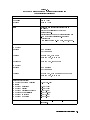
Title & Document Type:
70000 Series Spectrum Analyzer and 70900B Oscillator
Installation and Verification Manual
Manual Part Number: 70900-90314
Revision Date: December 1, 1996
HP References in this Manual
This manual may contain references to HP or Hewlett-Packard. Please note that HewlettPackard's former test and measurement, semiconductor products and chemical analysis
businesses are now part of Agilent Technologies. We have made no changes to this
manual copy. The HP XXXX referred to in this document is now the Agilent XXXX.
For example, model number HP8648A is now model number Agilent 8648A.
About this Manual
We’ve added this manual to the Agilent website in an effort to help you support your
product. This manual provides the best information we could find. It may be incomplete
or contain dated information, and the scan quality may not be ideal. If we find a better
copy in the future, we will add it to the Agilent website.
Support for Your Product
Agilent no longer sells or supports this product. You will find any other available
product information on the Agilent Test & Measurement website:
www.tm.agilent.com
Search for the model number of this product, and the resulting product page will guide
you to any available information. Our service centers may be able to perform calibration
if no repair parts are needed, but no other support from Agilent is available.
Installation and Verication Manual
HP 70000 Series Modular
Spectrum Analyzer System
HP 70900B Local Oscillator
Source-Controlled Modules
ABCDE
HP Part No. 70900-90314
Printed in USA December 1996
Edition A.0.0
Notice
The information contained in this document is subject to change without notice.
Hewlett-Packard makes no warranty of any kind with regard to this material, including,
but not limited to, the implied warranties of merchantability and tness for a particular
purpose. Hewlett-Packard shall not be liable for errors contained herein or for incidental or
consequential damages in connection with the furnishing, performance, or use of this material.
Restricted Rights Legend.
Use, duplication, or disclosure by the U.S. Government is subject to restrictions as set forth
in subparagraph (c) (1) (ii) of the Rights in Technical Data and Computer Software clause at
DFARS 252.227-7013 for DOD agencies, and subparagraphs (c) (1) and (c) (2) of the Commercial
Computer Software Restricted Rights clause at FAR 52.227-19 for other agencies.
c Copyright Hewlett-Packard Company 1990|1994, 1996
All Rights Reserved. Reproduction, adaptation, or translation without prior written permission
is prohibited, except as allowed under the copyright laws.
1400 Fountaingrove Parkway, Santa Rosa, CA 95403-1799, USA
Certication
Hewlett-Packard Company certies that this product met its published specications at the
time of shipment from the factory. Hewlett-Packard further certies that its calibration
measurements are traceable to the United States National Institute of Standards and
Technology, to the extent allowed by the Institute's calibration facility, and to the calibration
facilities of other International Standards Organization members.
Warranty
This Hewlett-Packard instrument product is warranted against defects in material and
workmanship for a period of one year from date of shipment. During the warranty period,
Hewlett-Packard Company will, at its option, either repair or replace products which prove to
be defective.
For warranty service or repair, this product must be returned to a service facility designated by
Hewlett-Packard. Buyer shall prepay shipping charges to Hewlett-Packard and Hewlett-Packard
shall pay shipping charges to return the product to Buyer. However, Buyer shall pay all
shipping charges, duties, and taxes for products returned to Hewlett-Packard from another
country.
Hewlett-Packard warrants that its software and rmware designated by Hewlett-Packard for
use with an instrument will execute its programming instructions when properly installed on
that instrument. Hewlett-Packard does not warrant that the operation of the instrument, or
software, or rmware will be uninterrupted or error-free.
Limitation of Warranty
The foregoing warranty shall not apply to defects resulting from improper or inadequate
maintenance by Buyer, Buyer-supplied software or interfacing, unauthorized modication or
misuse, operation outside of the environmental specications for the product, or improper
site preparation or maintenance.
NO OTHER WARRANTY IS EXPRESSED OR IMPLIED. HEWLETT-PACKARD SPECIFICALLY
DISCLAIMS THE IMPLIED WARRANTIES OF MERCHANTABILITY AND FITNESS FOR A
PARTICULAR PURPOSE.
Exclusive Remedies
THE REMEDIES PROVIDED HEREIN ARE BUYER'S SOLE AND EXCLUSIVE REMEDIES.
HEWLETT-PACKARD SHALL NOT BE LIABLE FOR ANY DIRECT, INDIRECT, SPECIAL,
INCIDENTAL, OR CONSEQUENTIAL DAMAGES, WHETHER BASED ON CONTRACT, TORT,
OR ANY OTHER LEGAL THEORY.
Assistance
Product maintenance agreements and other customer assistance agreements are available for
Hewlett-Packard products.
For any assistance, contact your nearest Hewlett-Packard Sales and Service Oce.
iii
Safety Symbols
The following safety symbols are used throughout this manual. Familiarize yourself with each
of the symbols and its meaning before operating this instrument.
CAUTION
The CAUTION sign denotes a hazard. It calls attention to a procedure which, if
not correctly performed or adhered to, could result in damage to or destruction
of the product or the user's work. Do not proceed beyond a CAUTION sign
until the indicated conditions are fully understood and met.
WARNING The WARNING sign denotes a hazard. It calls attention to a procedure
which, if not correctly performed or adhered to, could result in injury
to the user. Do not proceed beyond a WARNING sign until the indicated
conditions are fully understood and met.
DANGER
iv
The DANGER sign denotes an imminent hazard to people. It warns the
reader of a procedure which, if not correctly performed or adhered to,
could result in injury or loss of life. Do not proceed beyond a DANGER
sign until the indicated conditions are fully understood and met.
General Safety Considerations
WARNING
The instructions in this document are for use by qualied personnel
only. To avoid electrical shock, do not perform any servicing unless you
are qualied to do so.
The opening of covers or removal of parts is likely to expose dangerous
voltages. Disconnect the instrument from all voltage sources while it is
being opened.
The power cord is connected to internal capacitors that may remain live
for ve seconds after disconnecting the plug from its power supply.
This is a Safety Class 1 Product (provided with a protective earthing
ground incorporated in the power cord). The mains plug shall only be
inserted in a socket outlet provided with a protective earth contact.
Any interruption of the protective conductor inside or outside of the
instrument is likely to make the instrument dangerous. Intentional
interruption is prohibited.
For continued protection against re hazard, replace fuse only with
same type and ratings, (type nA/nV). The use of other fuses or materials
is prohibited.
WARNING
Before this instrument is switched on, make sure it has been properly
grounded through the protective conductor of the ac power cable to a
socket outlet provided with protective earth contact.
Any interruption of the protective (grounding) conductor, inside
or outside the instrument, or disconnection of the protective earth
terminal can result in personal injury.
Before this instrument is switched on, make sure its primary power
circuitry has been adapted to the voltage of the ac power source.
Failure to set the ac power input to the correct voltage could cause
damage to the instrument when the ac power cable is plugged in.
v
Contents
1. General Information
Manual Conventions . . . . . . . . . . . . . . . . . . . . . . . . .
Before Operation . . . . . . . . . . . . . . . . . . . . . . . . . .
Initial Inspection . . . . . . . . . . . . . . . . . . . . . . . . . . .
HP 70900B Local Oscillator Source . . . . . . . . . . . . . . . . . .
HP 70900B Local Oscillator Source Front-Panel Features . . . . . . .
HP 70900B Local Oscillator Source Rear-Panel Features . . . . . . .
HP 70900B Local Oscillator Source Options . . . . . . . . . . . . .
HP 70900B Local Oscillator Source Accessories . . . . . . . . . . . .
Preparing an HP 70000 System for Use . . . . . . . . . . . . . . . .
System Operating Requirements . . . . . . . . . . . . . . . . . .
Initial System Power-On . . . . . . . . . . . . . . . . . . . . . .
System Calibration Certication . . . . . . . . . . . . . . . . . .
Instrument Keypad for a Spectrum Analyzer . . . . . . . . . . . . .
System Rack-Mount and Cabinet Interconnect Installation . . . . . . .
Rack-Mounting . . . . . . . . . . . . . . . . . . . . . . . . . .
Rack-Mounting with Slides . . . . . . . . . . . . . . . . . . . . .
Interconnecting Instrument Cabinets . . . . . . . . . . . . . . . .
Line Voltage Selection . . . . . . . . . . . . . . . . . . . . . . . .
400 Hz Option for the Mainframe and Stand-Alone Display . . . . . . .
System Line Fuse Replacement . . . . . . . . . . . . . . . . . . . .
Optional Mainframe Rear-Fan Filter . . . . . . . . . . . . . . . . . .
System Power Cables . . . . . . . . . . . . . . . . . . . . . . . . .
Display Screen Cleaning . . . . . . . . . . . . . . . . . . . . . . .
External Power Pack for the HP 70310A Precision Frequency Reference
Preparing a Static-Safe Work Station . . . . . . . . . . . . . . . .
If You Need to Contact Hewlett-Packard . . . . . . . . . . . . . . .
Returning Your Instrument to Hewlett-Packard . . . . . . . . . . .
2. Installation
HP-MSIB/HP-IB Addressing . . . . . . . . . . . . . . .
Modular Measurement System Terms . . . . . . . . .
Functional Terms . . . . . . . . . . . . . . . . .
Structural Terms . . . . . . . . . . . . . . . . . .
Address Map Protocol . . . . . . . . . . . . . . . .
Address Matrix . . . . . . . . . . . . . . . . . .
Display-Response Area . . . . . . . . . . . . . . .
HP-IB Access . . . . . . . . . . . . . . . . . . .
Addressing Elements . . . . . . . . . . . . . . . . .
Master Elements . . . . . . . . . . . . . . . . . .
Sub-Master Elements . . . . . . . . . . . . . . . .
Slave Elements . . . . . . . . . . . . . . . . . .
Slave Area Boundaries . . . . . . . . . . . . . . .
Independent Elements . . . . . . . . . . . . . . .
Addressing Order Requirements for HP 70000 Systems .
Default Addressing for Congured HP 70000 Systems
.
.
.
.
.
.
.
.
.
.
.
.
.
.
.
.
.
.
.
.
.
.
.
.
.
.
.
.
.
.
.
.
.
.
.
.
.
.
.
.
.
.
.
.
.
.
.
.
.
.
.
.
.
.
.
.
.
.
.
.
.
.
.
.
.
.
.
.
.
.
.
.
.
.
.
.
.
.
.
.
.
.
.
.
.
.
.
.
.
.
.
.
.
.
.
.
.
.
.
.
.
.
.
.
.
.
.
.
.
.
.
.
.
.
.
.
.
.
.
.
.
.
.
.
.
.
.
.
.
.
.
.
.
.
.
.
.
.
.
.
.
.
.
.
.
.
.
.
.
.
.
.
.
.
.
.
.
.
.
.
.
.
.
.
.
.
.
.
.
.
.
.
.
.
.
.
.
.
.
.
.
.
.
.
.
.
.
.
.
.
.
.
.
.
.
.
.
.
.
.
.
.
.
.
.
.
.
.
.
.
.
.
.
.
.
.
.
.
.
.
1-1
1-2
1-3
1-3
1-4
1-6
1-8
1-8
1-9
1-9
1-10
1-10
1-11
1-13
1-13
1-13
1-15
1-16
1-17
1-18
1-19
1-19
1-21
1-21
1-22
1-24
1-26
.
.
.
.
.
.
.
.
.
.
.
.
.
.
.
.
.
.
.
.
.
.
.
.
.
.
.
.
.
.
.
.
.
.
.
.
.
.
.
.
.
.
.
.
.
.
.
.
.
.
.
.
.
.
.
.
.
.
.
.
.
.
.
.
2-1
2-2
2-2
2-2
2-3
2-3
2-4
2-4
2-4
2-4
2-5
2-5
2-6
2-6
2-7
2-7
Contents-1
Addressing Criteria . . . . . . . . . . . . . . . . . . . . . . . . . . .
Row Addressing Priority . . . . . . . . . . . . . . . . . . . . . . . . .
Address Switches . . . . . . . . . . . . . . . . . . . . . . . . . . . . .
Master Address Switches . . . . . . . . . . . . . . . . . . . . . . . . .
Slave Address Switches . . . . . . . . . . . . . . . . . . . . . . . . .
Display Address Switches . . . . . . . . . . . . . . . . . . . . . . . . .
Module Removal and Installation . . . . . . . . . . . . . . . . . . . . . . .
Module Removal . . . . . . . . . . . . . . . . . . . . . . . . . . . . . .
Installation . . . . . . . . . . . . . . . . . . . . . . . . . . . . . . . .
Connecting the MSIB Cables on a \A" and \C" System . . . . . . . . . . . .
Connecting the MSIB Y-Cable on a \P" System . . . . . . . . . . . . . . . .
System Congurations for \A" and \C" Systems . . . . . . . . . . . . . . . .
HP 71100C Modular Spectrum Analyzer . . . . . . . . . . . . . . . . . . .
HP 71100C Modular Spectrum Analyzer with HP 70903A IF Section . . . . . .
HP 71100C Modular Spectrum Analyzer with HP 70700A Digitizer . . . . . .
HP 71100C Modular Spectrum Analyzer with HP 70903A IF Section and
HP 70700A Digitizer . . . . . . . . . . . . . . . . . . . . . . . . . .
HP 71100C Modular Spectrum Analyzer with HP 70300A RF Tracking Generator
HP 71200C Modular Spectrum Analyzer . . . . . . . . . . . . . . . . . . .
HP 71200C Modular Spectrum Analyzer with HP 70903A IF Section . . . . . .
HP 71200C Modular Spectrum Analyzer Deleting HP 70902A IF Section, with
HP 70903A IF Section and HP 70907B External Millimeter Interface Module
HP 71200C Modular Spectrum Analyzer Deleting HP 70905A RF Section, with
HP 70905B RF Section/HP 70600A Preselector . . . . . . . . . . . . . .
HP 71200C Modular Spectrum Analyzer Deleting HP 70905A RF Section, with
HP 70905B RF Section/HP 70600A Preselector/HP 70301A Microwave
Tracking Generator . . . . . . . . . . . . . . . . . . . . . . . . . . .
HP 71209A Microwave Spectrum Analyzer . . . . . . . . . . . . . . . . .
HP 71210C Microwave Spectrum Analyzer . . . . . . . . . . . . . . . . .
HP 71400C Lightwave Signal Analyzer . . . . . . . . . . . . . . . . . . .
HP 71400C Lightwave Signal Analyzer with HP 70300A RF Tracking Generator
and HP 70301A Microwave Tracking Generator . . . . . . . . . . . . .
HP 71401C Lightwave Signal Analyzer . . . . . . . . . . . . . . . . . . .
HP 71401C Lightwave Signal Analyzer with an HP 70300A
RF Tracking Generator . . . . . . . . . . . . . . . . . . . . . . . . .
System Congurations for \P" Systems . . . . . . . . . . . . . . . . . . . .
General Guidelines for Module Placement . . . . . . . . . . . . . . . . . .
HP 71100P Modular Spectrum Analyzer . . . . . . . . . . . . . . . . . . .
HP 71100P Modular Spectrum Analyzer with HP 70903A IF Section . . . . . .
HP 71100P Modular Spectrum Analyzer with HP 70700A Digitizer . . . . . .
HP 71100P Modular Spectrum Analyzer with HP 70903A IF Section and
HP 70700A Digitizer . . . . . . . . . . . . . . . . . . . . . . . . . .
HP 71100P Modular Spectrum Analyzer with HP 70300A RF Tracking Generator
HP 71200P Modular Spectrum Analyzer . . . . . . . . . . . . . . . . . . .
HP 71200P Modular Spectrum Analyzer with HP 70903A IF Section . . . . . .
HP 71200P Modular Spectrum Analyzer Deleting HP 70902A IF Section, with
HP 70903A IF Section and HP 70907B External Millimeter Interface Module
HP 71200P Modular Spectrum Analyzer Deleting HP 70905A RF Section, with
HP 70905B RF Section/HP 70600A Preselector . . . . . . . . . . . . . .
HP 71200P Modular Spectrum Analyzer Deleting HP 70905A RF Section, with
HP 70905B RF Section/HP 70600A Preselector/HP 70301A Microwave
Tracking Generator . . . . . . . . . . . . . . . . . . . . . . . . . . .
HP 71209P Microwave Spectrum Analyzer . . . . . . . . . . . . . . . . .
HP 71210P Microwave Spectrum Analyzer . . . . . . . . . . . . . . . . .
Contents-2
2-8
2-10
2-10
2-11
2-12
2-13
2-15
2-15
2-15
2-16
2-17
2-18
2-20
2-22
2-24
2-26
2-28
2-30
2-32
2-34
2-36
2-38
2-40
2-42
2-44
2-46
2-49
2-51
2-53
2-53
2-56
2-58
2-60
2-62
2-64
2-66
2-68
2-70
2-72
2-74
2-77
2-79
HP 71210P Microwave Spectrum Analyzer with HP 70907B external millimeter
interface module Added . . . . . . . . . . . . . . . . . . . . . . . .
System Replaceable Parts . . . . . . . . . . . . . . . . . . . . . . . . . . .
Ordering Information . . . . . . . . . . . . . . . . . . . . . . . . . . .
Direct Mail-Order System . . . . . . . . . . . . . . . . . . . . . . . . . .
3. Specications and Characteristics
System Specications . . . . . . . . . . . . . . . . . . . . . . . . . . . .
System Components . . . . . . . . . . . . . . . . . . . . . . . . . . . .
HP 71100C Modular Spectrum Analyzer Specications and Characteristics . . . .
HP 71200C Modular Spectrum Analyzer Specications and Characteristics
[Including Option 001] . . . . . . . . . . . . . . . . . . . . . . . . . .
HP 71209A Microwave Spectrum Analyzer Specications and Characteristics . .
HP 71209A Microwave Spectrum Analyzer Specications and Characteristics with
External Mixers . . . . . . . . . . . . . . . . . . . . . . . . . . . . .
HP 71210C Microwave Spectrum Analyzer Specications and Characteristics . .
System Specication Changes with HP 70620B Preamplier/HP 70621A
Preamplier . . . . . . . . . . . . . . . . . . . . . . . . . . . . . . .
System Specication and Characteristic Changes with HP 70903A IF Section . .
System Specication and Characteristic Changes with HP 70907A External
Millimeter Interface Module (EMIM) . . . . . . . . . . . . . . . . . . . .
System Specication and Characteristic Changes with HP 70907B External
Millimeter Interface Module (EMIM) . . . . . . . . . . . . . . . . . . . .
System Specication and Characteristic Changes with HP 70905B RF Section/
HP 70600A Preselector or HP 70906B RF Section/HP 70601A Preselector . .
HP 71400C Lightwave Signal Analyzer Specications and Characteristics . . . .
HP 71400C Option 850 Lightwave Signal Analyzer Specications and
Characteristics . . . . . . . . . . . . . . . . . . . . . . . . . . . . . .
HP 71401C Lightwave Signal Analyzer Specications and Characteristics . . . .
HP 71401C Option 850 Lightwave Signal Analyzer Specications and
Characteristics . . . . . . . . . . . . . . . . . . . . . . . . . . . . . .
Physical Dimensions of the HP 70004A Color Display and HP 70001A Mainframe
Module Input and Output Characteristics . . . . . . . . . . . . . . . . . . .
HP 70310A Precision Frequency Reference . . . . . . . . . . . . . . . . .
HP 70600A Preselector/HP 70601A Preselector . . . . . . . . . . . . . . .
HP 70810B Lightwave Section and HP 70810B Option 850 Lightwave Section .
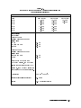
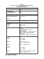
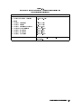
HP 70900B Local Oscillator Source . . . . . . . . . . . . . . . . . . . . .
HP 70902A IF Section . . . . . . . . . . . . . . . . . . . . . . . . . . .
HP 70903A IF Section . . . . . . . . . . . . . . . . . . . . . . . . . . .
HP 70904A RF Section . . . . . . . . . . . . . . . . . . . . . . . . . . .
HP 70905A RF Section . . . . . . . . . . . . . . . . . . . . . . . . . . .
HP 70906A RF Section . . . . . . . . . . . . . . . . . . . . . . . . . . .
HP 70905B RF Section and HP 70906B RF Section . . . . . . . . . . . . . .
HP 70907A External Millimeter Interface Module . . . . . . . . . . . . . .
HP 70907B External Millimeter Interface Module . . . . . . . . . . . . . .
HP 70908A RF Section . . . . . . . . . . . . . . . . . . . . . . . . . . .
HP 70909A RF Section and HP 70910A RF Section . . . . . . . . . . . . . .
2-81
2-83
2-83
2-83
3-1
3-2
3-3
3-10
3-18
3-26
3-31
3-40
3-48
3-50
3-55
3-62
3-67
3-71
3-75
3-79
3-83
3-84
3-85
3-87
3-88
3-89
3-90
3-91
3-92
3-93
3-95
3-97
3-98
3-99
3-100
3-102
Contents-3
4. System Operation Verication
Shipment Contents . . . . . . . . . . . . . . . . . . . . . . . . . . . . . .
Software Version . . . . . . . . . . . . . . . . . . . . . . . . . . . . . .
Software/Hardware Compatibility . . . . . . . . . . . . . . . . . . . . . . .
Computer Hardware Compatibility . . . . . . . . . . . . . . . . . . . . .
Computer Language Compatibility . . . . . . . . . . . . . . . . . . . . .
Printer Compatibility . . . . . . . . . . . . . . . . . . . . . . . . . . . .
Typographic Conventions . . . . . . . . . . . . . . . . . . . . . . . . . .
Required Test Equipment . . . . . . . . . . . . . . . . . . . . . . . . . . .
Operation Verication Test Software Overview . . . . . . . . . . . . . . . . .
Testing Multiple Systems . . . . . . . . . . . . . . . . . . . . . . . . . .
Types of Error Messages or Warnings Dened . . . . . . . . . . . . . . . .
Limited Cal Dened . . . . . . . . . . . . . . . . . . . . . . . . . . . .
Single Tests Dened . . . . . . . . . . . . . . . . . . . . . . . . . . . .
Test Results . . . . . . . . . . . . . . . . . . . . . . . . . . . . . . . .
Printing Test Results . . . . . . . . . . . . . . . . . . . . . . . . . . . .
Start-Up Procedures . . . . . . . . . . . . . . . . . . . . . . . . . . . . .
Conguring the Hardware . . . . . . . . . . . . . . . . . . . . . . . . .
Installing Operation Verication Software . . . . . . . . . . . . . . . . . .
Menus . . . . . . . . . . . . . . . . . . . . . . . . . . . . . . . . . . .
Menu Structure . . . . . . . . . . . . . . . . . . . . . . . . . . . . . .
Common Edit and Command Screen Menu Keys . . . . . . . . . . . . . . .
Edit Screen Menu keys . . . . . . . . . . . . . . . . . . . . . . . . . .
Command Screen Menu Keys . . . . . . . . . . . . . . . . . . . . . . .
Main Menu . . . . . . . . . . . . . . . . . . . . . . . . . . . . . . . .
Mass Storage Menu . . . . . . . . . . . . . . . . . . . . . . . . . . . .
Mass Storage Menu Volume Labels . . . . . . . . . . . . . . . . . . . .
Editing Mass Storage Menu Information . . . . . . . . . . . . . . . . . .
Parameter Menu . . . . . . . . . . . . . . . . . . . . . . . . . . . . . .
Equipment Menu . . . . . . . . . . . . . . . . . . . . . . . . . . . . .
Equipment Menu Edit Screen . . . . . . . . . . . . . . . . . . . . . . .
Equipment Menu Command Screen . . . . . . . . . . . . . . . . . . . .
Editing Calibration Data . . . . . . . . . . . . . . . . . . . . . . . . .
HP-MSIB Address Menu . . . . . . . . . . . . . . . . . . . . . . . . . .
Test Menu . . . . . . . . . . . . . . . . . . . . . . . . . . . . . . . . .
Test Descriptions . . . . . . . . . . . . . . . . . . . . . . . . . . . . . . .
Test Description List . . . . . . . . . . . . . . . . . . . . . . . . . . . . .
Calibrator Frequency Accuracy (for HP 70900A/B Local Oscillator Source) . . .
Calibrator Amplitude Accuracy (for HP 70900A/B Local Oscillator Source) . . .
Frequency Response (for HP 70904A RF Section) . . . . . . . . . . . . . .
Frequency Response (for HP 70905A RF Section, HP 70906A RF Section) . . .
Frequency Response (for HP 70600A Preselector/HP 70601A Preselector,
HP 70905B RF Section/HP 70906B RF Section) . . . . . . . . . . . . . .
Frequency Response (for HP 70908A RF Section) . . . . . . . . . . . . . .
Frequency Response (for HP 70908A RF Section and HP 70620B Preamplier) .
Frequency Response (for HP 70909A or HP 70910A RF Section ) . . . . . . .
Frequency Response (for HP 70600A Preselector/HP 70601A Preselector,
HP 70905A/B RF Section or HP 70906A/B RF Section, and HP 70620B
Preamplier) . . . . . . . . . . . . . . . . . . . . . . . . . . . . . .
Frequency Response (for HP 70904A RF Section and HP 70621A Preamplier) .
GSM System Calibration (for HP 71150C GSM Transmitter Tester or HP 71250C
GSM Transmitter Tester) . . . . . . . . . . . . . . . . . . . . . . . .
Frequency Span Accuracy . . . . . . . . . . . . . . . . . . . . . . . . .
Displayed Average Noise (using HP 70902A IF Section or HP 70903A IF Section)
GSM System Displayed Average Noise Level (using HP 70902A IF Section) . . .
Contents-4
4-1
4-2
4-2
4-2
4-2
4-3
4-4
4-5
4-6
4-6
4-7
4-7
4-7
4-7
4-7
4-8
4-8
4-9
4-11
4-11
4-11
4-11
4-11
4-13
4-14
4-14
4-14
4-15
4-17
4-17
4-18
4-18
4-19
4-20
4-27
4-28
4-29
4-30
4-31
4-32
4-33
4-35
4-36
4-38
4-40
4-42
4-44
4-45
4-46
4-47
Log Fidelity (for HP 70902A IF Section or HP 70903A IF Section) . . . . . . .
Resolution Bandwidth Tests (for HP 70902A IF Section or HP 70903A IF Section)
Calibrator Amplitude Accuracy (using HP 70907A External Millimeter Interface
Module) . . . . . . . . . . . . . . . . . . . . . . . . . . . . . . . .
Calibrator Amplitude Accuracy (using HP 70907B External Millimeter Interface
Module) . . . . . . . . . . . . . . . . . . . . . . . . . . . . . . . .
LO Output Amplitude (from HP 70907A/B External Millimeter Interface Module)
Log Fidelity | Using HP 70907A/B External Millimeter Interface Module (for
HP 70902A IF Section and HP 70903A IF Section) . . . . . . . . . . . .
Resolution Bandwidth | Using HP 70907A External Millimeter Interface Module
(for HP 70902A IF Section or HP 70903A IF Section) . . . . . . . . . . .
Resolution Bandwidth | Using HP 70907B External Millimeter Interface Module
(HP 70902A IF Section or HP 70903A IF Section) . . . . . . . . . . . . .
Test Limit Changes . . . . . . . . . . . . . . . . . . . . . . . . . . . . .
Error and Status Messages . . . . . . . . . . . . . . . . . . . . . . . . .
5. Error Messages
User Application Errors 0001 { 0999 .
Operating Errors 2000 { 2999 . . . . .
Hardware Warning Errors 6000 { 6999
Hardware Broken Errors 7000 { 7999 .
Computation Errors 8000 { 8999 . . .
Factory-Use Only Errors 9000 { 9999 .
.
.
.
.
.
.
.
.
.
.
.
.
.
.
.
.
.
.
.
.
.
.
.
.
.
.
.
.
.
.
.
.
.
.
.
.
.
.
.
.
.
.
.
.
.
.
.
.
.
.
.
.
.
.
.
.
.
.
.
.
.
.
.
.
.
.
.
.
.
.
.
.
.
.
.
.
.
.
.
.
.
.
.
.
.
.
.
.
.
.
.
.
.
.
.
.
.
.
.
.
.
.
.
.
.
.
.
.
.
.
.
.
.
.
.
.
.
.
.
.
4-48
4-49
4-50
4-51
4-52
4-53
4-54
4-56
4-58
4-59
5-2
5-13
5-22
5-25
5-35
5-36
Index
Contents-5
Figures
1-1.
1-2.
1-3.
1-4.
1-5.
1-6.
1-7.
1-8.
1-9.
1-10.
1-11.
1-12.
2-1.
2-2.
2-3.
2-4.
2-5.
2-6.
2-7.
2-8.
2-9.
2-10.
2-11.
2-12.
2-13.
2-14.
2-15.
2-16.
2-17.
2-18.
2-19.
2-20.
2-21.
2-22.
2-23.
HP 70900B Local Oscillator Source Front-Panel Features . . . . . . . . . . .
HP 70900B Local Oscillator Source Rear-Panel Features . . . . . . . . . . .
Spectrum Analyzer Instrument Keypad . . . . . . . . . . . . . . . . . . .
Front Handle Removal and Rack Mounting . . . . . . . . . . . . . . . . .
Interconnecting System II Cabinets . . . . . . . . . . . . . . . . . . . . .
Line Voltage Selector . . . . . . . . . . . . . . . . . . . . . . . . . . . .
Line Fuse Removal and Replacement . . . . . . . . . . . . . . . . . . . .
Rear-Fan Filter Installation . . . . . . . . . . . . . . . . . . . . . . . . .
AC Power Cords . . . . . . . . . . . . . . . . . . . . . . . . . . . . . .
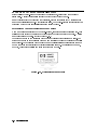
External Power Pack . . . . . . . . . . . . . . . . . . . . . . . . . . . .
Static-Safe Work Station . . . . . . . . . . . . . . . . . . . . . . . . . .
Typical Serial Number Label . . . . . . . . . . . . . . . . . . . . . . . .
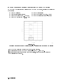
Address Matrix . . . . . . . . . . . . . . . . . . . . . . . . . . . . . .
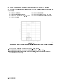
Master/Slave Address Matrix . . . . . . . . . . . . . . . . . . . . . . . .
Sub-Master Address Matrix . . . . . . . . . . . . . . . . . . . . . . . . .
HP 70900B Local Oscillator Source Address Switch . . . . . . . . . . . . . .
Slave Element Address Switches . . . . . . . . . . . . . . . . . . . . . .
HP 70206A System Graphics Display Address Switches . . . . . . . . . . . .
HP 70004A Color Display Address Switches . . . . . . . . . . . . . . . . .
Module Removal/Replacement . . . . . . . . . . . . . . . . . . . . . . .
HP 70001A Mainframe to HP 70004A Color Display Cabling . . . . . . . . .
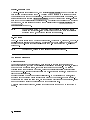
Address Map for HP 71100C Modular Spectrum Analyzer . . . . . . . . . . .
HP 71100C Modular Spectrum Analyzer Rear Panel Cabling . . . . . . . . . .
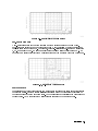
Address Map for HP 71100C Modular Spectrum Analyzer with HP 70903A
IF Section . . . . . . . . . . . . . . . . . . . . . . . . . . . . . . .
HP 71100C Modular Spectrum Analyzer Rear Panel Cabling with HP 70903A
IF Section . . . . . . . . . . . . . . . . . . . . . . . . . . . . . . .
Address Map for HP 71100C Modular Spectrum Analyzer with HP 70700A
Digitizer . . . . . . . . . . . . . . . . . . . . . . . . . . . . . . . .
HP 71100C Modular Spectrum Analyzer Rear Panel Cabling with HP 70700A
Digitizer . . . . . . . . . . . . . . . . . . . . . . . . . . . . . . . .
Address Map for HP 71100C Modular Spectrum Analyzer with HP 70903A
IF Section and HP 70700A Digitizer . . . . . . . . . . . . . . . . . . .
HP 71100C Modular Spectrum Analyzer Rear Panel Cabling with HP 70903A
IF Section and HP 70700A Digitizer . . . . . . . . . . . . . . . . . . .
Address Map for HP 71100C Modular Spectrum Analyzer with HP 70300A
RF Tracking Generator . . . . . . . . . . . . . . . . . . . . . . . . .
HP 71100C Modular Spectrum Analyzer Rear Panel Cabling with an HP 70300A
RF Tracking Generator . . . . . . . . . . . . . . . . . . . . . . . . .
Address Map for HP 71200C Modular Spectrum Analyzer . . . . . . . . . . .
HP 71200C Modular Spectrum Analyzer Rear Panel Cabling . . . . . . . . . .
Address Map for HP 71200C Modular Spectrum Analyzer with HP 70903A
IF Section . . . . . . . . . . . . . . . . . . . . . . . . . . . . . . .
HP 71200C Modular Spectrum Analyzer Rear Panel Cabling with HP 70903A
IF Section . . . . . . . . . . . . . . . . . . . . . . . . . . . . . . .
Contents-6
1-5
1-7
1-12
1-14
1-15
1-16
1-18
1-19
1-20
1-21
1-22
1-24
2-3
2-5
2-5
2-12
2-12
2-13
2-14
2-15
2-16
2-20
2-21
2-22
2-23
2-24
2-25
2-26
2-27
2-28
2-29
2-30
2-31
2-32
2-33
2-24. Address Map for HP 71200C Modular Spectrum Analyzer Deleting HP 70902A
IF Section, with HP 70903A IF Section and HP 70907B External Millimeter
Interface Module . . . . . . . . . . . . . . . . . . . . . . . . . . . .
2-25. HP 71200C Modular Spectrum Analyzer Deleting HP 70902A IF Section, with
HP 70903A IF Section and HP 70907B External Millimeter Interface Module
Cabling . . . . . . . . . . . . . . . . . . . . . . . . . . . . . . . .
2-26. Address Map for HP 71200C Modular Spectrum Analyzer Deleting HP 70905A
RF Section, with HP 70905B RF Section/HP 70600A Preselector . . . . . .
2-27. HP 71200C Modular Spectrum Analyzer Deleting HP 70905A RF Section, with
HP 70905B RF Section/HP 70600A Preselector Cabling . . . . . . . . . .
2-28. Address Map for HP 71200C Modular Spectrum Analyzer Deleting HP 70905A
RF Section, with HP 70905B RF Section/HP 70600A Preselector/HP 70301A
Microwave Tracking Generator . . . . . . . . . . . . . . . . . . . . .
2-29. HP 71200C Modular Spectrum Analyzer Deleting HP 70905A RF Section, with
HP 70905B RF Section/HP 70600A Preselector/HP 70301A Microwave
Tracking Generator Cabling . . . . . . . . . . . . . . . . . . . . . . .
2-30. Address Map for HP 71209A Microwave Spectrum Analyzer . . . . . . . . .
2-31. HP 71209A Microwave Spectrum Analyzer Rear Panel Cabling . . . . . . . .
2-32. Address Map for HP 71210C Microwave Spectrum Analyzer . . . . . . . . .
2-33. HP 71210C Microwave Spectrum Analyzer Rear Panel Cabling . . . . . . . .
2-34. Address Map for HP 71400C Lightwave Signal Analyzer . . . . . . . . . . .
2-35. HP 71400C Lightwave Signal Analyzer Rear Panel Cabling . . . . . . . . . .
2-36. Address Map for HP 71400C Lightwave Signal Analyzer with HP 70300A
RF Tracking Generator and HP 70301A Microwave Tracking Generator . .
2-37. HP 71400C Lightwave Signal Analyzer with HP 70300A RF Tracking Generator
and HP 70301A Microwave Tracking Generator Rear Panel Cabling . . . .
2-38. Address Map for HP 71401C Lightwave Signal Analyzer . . . . . . . . . . .
2-39. HP 71401C Lightwave Signal Analyzer Rear-Panel Cabling . . . . . . . . . .
2-40. Address Map for HP 71401C Lightwave Signal Analyzer with an HP 70300A
RF Tracking Generator . . . . . . . . . . . . . . . . . . . . . . . . .
2-41. HP 71401C Lightwave Signal Analyzer Rear-Panel Cabling with an HP 70300A
RF Tracking Generator . . . . . . . . . . . . . . . . . . . . . . . . .
2-42. Address Map for HP 71100P Modular Spectrum Analyzer . . . . . . . . . . .
2-43. HP 71100P Modular Spectrum Analyzer Rear Panel Cabling . . . . . . . . . .
2-44. Address Map for HP 71100P Modular Spectrum Analyzer with HP 70903A
IF Section . . . . . . . . . . . . . . . . . . . . . . . . . . . . . . .
2-45. HP 71100P Modular Spectrum Analyzer Rear Panel Cabling with HP 70903A
IF Section . . . . . . . . . . . . . . . . . . . . . . . . . . . . . . .
2-46. Address Map for HP 71100P Modular Spectrum Analyzer with HP 70700A
Digitizer . . . . . . . . . . . . . . . . . . . . . . . . . . . . . . . .
2-47. HP 71100P Modular Spectrum Analyzer Rear Panel Cabling with HP 70700A
Digitizer . . . . . . . . . . . . . . . . . . . . . . . . . . . . . . . .
2-48. Address Map for HP 71100P Modular Spectrum Analyzer with HP 70903A
IF Section and HP 70700A Digitizer . . . . . . . . . . . . . . . . . . .
2-49. HP 71100P Modular Spectrum Analyzer Rear Panel Cabling with HP 70903A
IF Section and HP 70700A Digitizer . . . . . . . . . . . . . . . . . . .
2-50. Address Map for HP 71100P Modular Spectrum Analyzer with HP 70300A
RF Tracking Generator . . . . . . . . . . . . . . . . . . . . . . . . .
2-51. HP 71100P Modular Spectrum Analyzer Rear Panel Cabling with an HP 70300A
RF Tracking Generator . . . . . . . . . . . . . . . . . . . . . . . . .
2-52. Address Map for HP 71200P Modular Spectrum Analyzer . . . . . . . . . . .
2-53. HP 71200P Modular Spectrum Analyzer Rear Panel Cabling . . . . . . . . . .
2-54. Address Map for HP 71200P Modular Spectrum Analyzer with HP 70903A
IF Section . . . . . . . . . . . . . . . . . . . . . . . . . . . . . . .
2-34
2-35
2-36
2-37
2-38
2-39
2-40
2-41
2-42
2-43
2-44
2-45
2-46
2-48
2-49
2-50
2-51
2-52
2-56
2-57
2-58
2-59
2-60
2-61
2-62
2-63
2-64
2-65
2-66
2-67
2-68
Contents-7
2-55. HP 71200P Modular Spectrum Analyzer Rear Panel Cabling with HP 70903A
IF Section . . . . . . . . . . . . . . . . . . . . . . . . . . . . . . .
2-56. Address Map for HP 71200P Modular Spectrum Analyzer Deleting HP 70902A
IF Section, with HP 70903A IF Section and HP 70907B External Millimeter
Interface Module . . . . . . . . . . . . . . . . . . . . . . . . . . . .
2-57. HP 71200P Modular Spectrum Analyzer Deleting HP 70902A IF Section, with
HP 70903A IF Section and HP 70907B External Millimeter Interface Module
Cabling . . . . . . . . . . . . . . . . . . . . . . . . . . . . . . . .
2-58. Address Map for HP 71200P Modular Spectrum Analyzer Deleting HP 70905A
RF Section, with HP 70905B RF Section/HP 70600A Preselector . . . . . .
2-59. HP 71200P Modular Spectrum Analyzer Deleting HP 70905A RF Section, with
HP 70905B RF Section/HP 70600A Preselector Cabling . . . . . . . . . .
2-60. Address Map for HP 71200P Modular Spectrum Analyzer Deleting HP 70905A
RF Section, with HP 70905B RF Section/HP 70600A Preselector/HP 70301A
Microwave Tracking Generator . . . . . . . . . . . . . . . . . . . . .
2-61. HP 71200P Modular Spectrum Analyzer Deleting HP 70905A RF Section, with
HP 70905B RF Section/HP 70600A Preselector/HP 70301A Microwave
Tracking Generator Cabling . . . . . . . . . . . . . . . . . . . . . . .
2-62. Address Map for HP 71209P Microwave Spectrum Analyzer . . . . . . . . .
2-63. HP 71209P Microwave Spectrum Analyzer Rear Panel Cabling . . . . . . . .
2-64. Address Map for HP 71210P Microwave Spectrum Analyzer . . . . . . . . .
2-65. HP 71210P Microwave Spectrum Analyzer Rear Panel Cabling . . . . . . . .
2-66. Address Map for HP 71210P Microwave Spectrum Analyzer with HP 70907B
external millimeter interface module Added . . . . . . . . . . . . . . .
2-67. HP 71210P Microwave Spectrum Analyzer with HP 70907B External Millimeter
Interface Module Rear Panel Cabling . . . . . . . . . . . . . . . . . . .
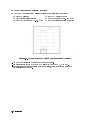
3-1. HP 70004A Color Display Physical Dimensions . . . . . . . . . . . . . . . .
3-2. HP 70001A Mainframe Physical Dimensions . . . . . . . . . . . . . . . . .
4-1. Main Menu keys . . . . . . . . . . . . . . . . . . . . . . . . . . . . . .
4-2. Mass Storage Menu and Parameter Menu Keys . . . . . . . . . . . . . . . .
4-3. Equipment Menu and HP-MSIB Map Screen Menu Keys . . . . . . . . . . .
4-4. Test Menu Keys . . . . . . . . . . . . . . . . . . . . . . . . . . . . . .
4-5. Frequency Response Test Setup . . . . . . . . . . . . . . . . . . . . . . .
Contents-8
2-69
2-70
2-71
2-72
2-73
2-74
2-76
2-77
2-78
2-79
2-80
2-81
2-82
3-83
3-83
4-23
4-24
4-25
4-26
4-38
Tables
1-1.
1-2.
1-3.
1-4.
1-5.
1-6.
1-7.
1-8.
1-9.
1-10.
1-11.
2-1.
2-2.
2-3.
3-1.
3-2.
3-3.
3-4.
3-4.
3-4.
3-4.
3-4.
3-4.
3-4.
3-5.
3-6.
3-7.
3-8.
3-8.
3-8.
3-9.
3-9.
3-9.
3-10.
3-11.
3-12.
3-13.
3-14.
3-15.
3-16.
3-17.
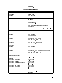
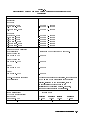
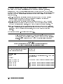
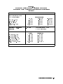
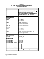
HP 70900B Local Oscillator Source Front-Panel Feature Descriptions . . . . .
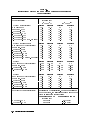
HP 70900B Local Oscillator Source Rear-Panel Feature Descriptions . . . . . .
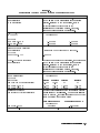
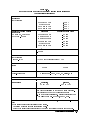
Accessories Shipped When Module is Ordered Separately . . . . . . . . . . .
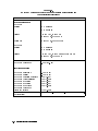
Instrument Keypad Function Keys . . . . . . . . . . . . . . . . . . . . .
Interconnect Hardware . . . . . . . . . . . . . . . . . . . . . . . . . .
Static-Safe ESD Accessories . . . . . . . . . . . . . . . . . . . . . . . .
Hewlett-Packard Sales and Service Oces . . . . . . . . . . . . . . . . . .
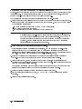
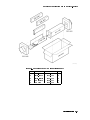
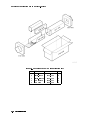
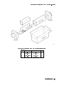
Packaging for a 1/8 Module (Instrument) . . . . . . . . . . . . . . . . . .
Packaging for a 2/8 Module (Instrument) . . . . . . . . . . . . . . . . . .
Packaging for a 3/8 Module (Instrument) . . . . . . . . . . . . . . . . . .
Packaging for an 8/8 Module (Instrument) . . . . . . . . . . . . . . . . . .
Decimal Equivalent of Binary Address . . . . . . . . . . . . . . . . . . .
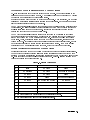
Default Address Map . . . . . . . . . . . . . . . . . . . . . . . . . . . .
System Replacement Parts Listing . . . . . . . . . . . . . . . . . . . . . .
Model Numbers, Modules, and System Options . . . . . . . . . . . . . . . .
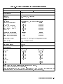
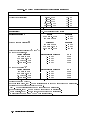
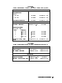
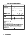
HP 71100C Modular Spectrum Analyzer Specications and Characteristics . . .
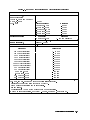
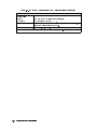
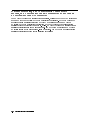
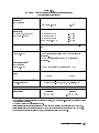
HP 71200C Modular Spectrum Analyzer Specications and Characteristics . . .
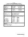
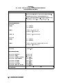
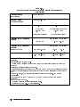
HP 71209A Microwave Spectrum Analyzer Specications and Characteristics .
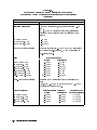
HP 71209A Specications and Characteristics (continued) . . . . . . . . . .
HP 71209A Specications and Characteristics (continued) . . . . . . . . . .
HP 71209A Specications and Characteristics (continued) . . . . . . . . . .
HP 71209A Specications and Characteristics (continued) . . . . . . . . . .
HP 71209A Specications and Characteristics (continued) . . . . . . . . . .
HP 71209A Specications and Characteristics (continued) . . . . . . . . . .
HP 71209A Specications and Characteristics (continued) . . . . . . . . . .
HP 71209A Microwave Spectrum Analyzer Specications and Characteristics
When Used with HP 11970 and HP 11974 External Mixers . . . . . . . .
HP 71210C Microwave Spectrum Analyzer Specications and Characteristics .
Specications Aected When an HP 70620B Preamplier Is Added . . . . . .
Specications Aected When an HP 70620B Preamplier Is Added (continued)
Specications Aected When an HP 70620B Preamplier Is Added (continued)
Specications Aected When an HP 70620B Option 001 Preamplier Is Added .
Specications Aected When an HP 70620B Option 001 Preamplier Is Added
(continued) . . . . . . . . . . . . . . . . . . . . . . . . . . . . . .
Specications Aected When an HP 70620B Option 001 Preamplier Is Added
(continued) . . . . . . . . . . . . . . . . . . . . . . . . . . . . . .
Specications Aected When an HP 70621A Preamplier Is Added . . . . . .
System Specications and Characteristics Aected by an HP 70903A IF Section
System Specications Aected When RF Section is Replaced by HP 70907A
External Millimeter Interface Module . . . . . . . . . . . . . . . . . .
System Specications Aected When One HP 70907A EMIM Is Added . . . . .
System Specication Changes for Each Additional HP 70907A EMIM Added . .
System Specications Aected When an RF Section Is Replaced by HP 70907B
external millimeter interface module . . . . . . . . . . . . . . . . . .
System Specications Aected When One HP 70907B EMIM Is added . . . . .
System Specication Changes for Each Additional HP 70907B EMIM . . . . .
1-4
1-6
1-8
1-11
1-15
1-23
1-25
1-27
1-28
1-29
1-30
2-3
2-7
2-84
3-2
3-3
3-10
3-18
3-19
3-20
3-21
3-22
3-23
3-24
3-25
3-26
3-31
3-40
3-42
3-43
3-44
3-45
3-46
3-47
3-48
3-50
3-54
3-54
3-56
3-61
3-61
Contents-9
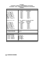
3-18. HP 70905B RF Section/HP 70600A Preselector or HP 70906B RF Section/
HP 70601A Preselector Specications and Characteristics . . . . . .
3-19. HP 71400C Lightwave Signal Analyzer Specications and Characteristics
3-20. HP 71400C Option 850 Lightwave Signal Analyzer Specications and
Characteristics . . . . . . . . . . . . . . . . . . . . . . . . . .
3-21. HP 71401C Lightwave Signal Analyzer Specications and Characteristics
3-22. HP 71401C Option 850 Lightwave Signal Analyzer Specications and
Characteristics . . . . . . . . . . . . . . . . . . . . . . . . . .
4-1. External Test Equipment . . . . . . . . . . . . . . . . . . . . . . .
4-2. Required Accessories . . . . . . . . . . . . . . . . . . . . . . . . .
4-3. Operation Verication Tests . . . . . . . . . . . . . . . . . . . . . .
Contents-10
. . .
. . .
3-63
3-68
. . .
. . .
3-72
3-76
.
.
.
.
3-80
4-5
4-6
4-28
.
.
.
.
.
.
.
.
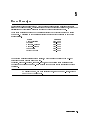
1
General Information
The HP 70000 Modular Spectrum Analyzer Installation and Verication Manual contains
information specic to the HP 70900B local oscillator source as well as information needed to
prepare an HP 70000 Series modular spectrum analyzer system for use.
This manual contains the following ve chapters:
Chapter 1 contains module-specic information about the HP 70900B local oscillator source,
compatibility information, and information needed to prepare an HP 70000 Series modular
spectrum analyzer system for use. This chapter also contains general information, such as
system rack-mounting, line-voltage selector location, electrostatic discharge precautions,
packaging requirements, and Hewlett-Packard sales and service oces locations.
Chapter 2 provides information about module addressing and installation, as well as
addressing and cable connection examples for various congurations of HP 70000 Series
modular spectrum analyzer systems.
Chapter 3 lists system specications and characteristics, as well as module input and output
characteristics for modules in HP 70000 Series modular spectrum analyzer systems.
Chapter 4 contains tests required to verify system operation.
Chapter 5 identies the error messages that are displayed when the system encounters
an error. The cause of the error message and a solution to the problem is included where
practical.
Manual Conventions
The following descriptions are used throughout this manual:
Keys physically on an instrument are represented in the following way:
Key . . . . . . . . . . . . . . . . . . . . . . . . . . . . . . . . . . . . . . . . . . . . . . . . . . . . . . . . . . . . . . . . . . . . . 4KEY5
Softkeys, keys dened by software or rmware, are represented in the following way:
Softkey . . . . . . . . . . . . . . . . . . . . . . . . . . . . . . . . . . . . . . . . . . . . . . . . . . . . . . . . . . . . . softkey
Text that appears on the display screen is represented in the following way:
Screen text . . . . . . . . . . . . . . . . . . . . . . . . . . . . . . . . . . . . . . . . . . . . . . . . . . . . . . . screen text
NNNNNNNNNNNNNNNNNNNNNNN
General Information 1-1
Before Operation
Before operating this module, familiarize yourself with any safety markings on the module and
read the following cautions and warnings. This module has been manufactured and tested
according to international safety standards.
Cautions and warnings must be followed to ensure the safe operation of the module and
protection of personnel. Refer to the summary of safety considerations at the front of this
manual and below before using the instrument.
DANGER
Before turning the system on, make sure it is grounded through the
protective conductor of the power cable to a socket outlet with
protective earth contact. Any interruption of the protective (grounding)
conductor inside or outside the instrument, or disconnection of the
protective earth terminal, can result in personal injury.
Before turning the system on, be sure the line voltage selector is set to
the correct voltage for the power source. Failure to do this may cause
damage (a blown fuse) to the system when the power cable is plugged
in.
Do not operate a 400 Hz Option instrument on a 400 Hz power line
without the attached in-line isolation transformer. Failure to follow this
precaution can result in personal injury.
Note
Do not use hand or laboratory paper towels to clean the display screen.
These abrasive materials may scratch the screen coating. (Refer to \Display
Screen Cleaning".)
Do not place labels on the back side of the front panel door. Damage may
result to labels due to opening and closing the front panel door. Labels
should be attached to the frame inside the door.
1-2 General Information
Initial Inspection
Inspect the shipping containers for damage. If a shipping container or cushioning material
is damaged, it should be kept until the contents of the shipment have been checked for
completeness and the module has been checked mechanically and electrically. To determine
what accessories should have been shipped with the module, refer to \HP 70900B Local
Oscillator Source Accessories". Run the operation verication tests to check electrical
performance. (Refer to Chapter 4.)
If the shipping contents are incomplete, or the module does not satisfy the verication
procedures, notify the nearest Hewlett-Packard Sales and Service Oce. Hewlett-Packard will
arrange for repair or replacement of the equipment without waiting for a claim settlement.
Retain the shipping materials for the carrier to inspect.
Undamaged shipping materials should be kept. Original Hewlett-Packard shipping materials, or
equivalent, are required for system or module reshipment. Substandard packaging may damage
the instrument. For more information, refer to \If You Need to Contact Hewlett-Packard".
HP 70900B Local Oscillator Source
The HP 70900B local oscillator source (LO) is a 1/4-width module that fullls three functions:
local oscillator, controller, and video processor.
The local oscillator circuitry supplies a swept signal that has a frequency range of
3.0 to 6.6 GHz. This signal is used by various modules and devices, including front-ends (RF
sections), tracking generators, and the external mixer interface module. For spans that are
less than or equal to 10 MHz, the sweep is fully synthesized using fractional-N techniques;
for spans that are greater than or equal to 10 MHz, lock-and-roll tuning is used.
The controller circuitry contains the system rmware. This rmware controls and coordinates
measurements between other system modules which are slave modules to the LO module.
Examples of slave modules are the RF sections, IF sections, and tracking generator modules.
The video processor circuitry digitizes the video signal received from the IF section and
processes this signal using normal (rosenfell), positive peak, negative peak, or sample
detection.
If the HP 70900B local oscillator source was ordered separately, not as part of a precongured
system, refer to Chapter 2 for addressing and installation information and examples of rear
panel cable connections. Refer to the HP 70004A Color Display User's Guide for instructions
on installing the spectrum analyzer instrument keypad into the HP 70004A color display. Then,
refer to \Preparing an HP 70000 System for Use".
General Information 1-3
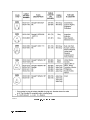
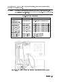
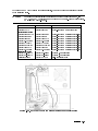
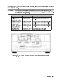
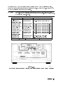
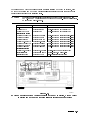
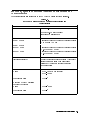
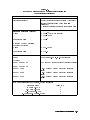
HP 70900B Local Oscillator Source Front-Panel Features
Note
It is normal for the ERR and ACT LEDs to ash on, then o, during the module
self-test. Self-test occurs each time the instrument is turned on.
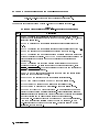
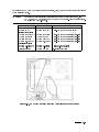
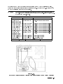
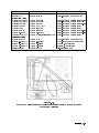
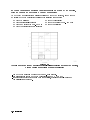
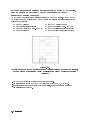
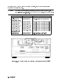
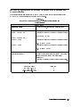
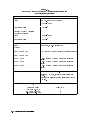
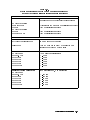
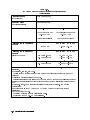
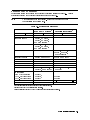
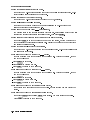
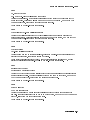
The numbers in the \Item" column of Table 1-1 refer to the callouts in Figure 1-1.
Table 1-1.
HP 70900B Local Oscillator Source Front-Panel Feature Descriptions
Item
Description
1
The RMT LED lights if the analyzer is addressed by a computer. In addition,
depending on the instructions received from the computer, the LSN, TLK, or SRQ
indicators will also light.
2
The LSN LED lights when the analyzer is receiving data or instructions over
HP-IB.
3
The TLK LED lights when the analyzer is sending data or instructions over HP-IB.
4
The SRQ LED lights when the analyzer has requested computer service.
5
The ACT LED lights when a module is making a measurement and its master has
keyboard control of the display. The ACT LED of a module is only operative when
there is a display in the system and when the instrument is performing a
measurement.
6
The ERR LED lights when there is a problem (error) related to one or more
modules in the system. To learn the nature of the error and its source, press
4DISPLAY5, 4REPORT ERRORS5. The screen displays the error code and identies the
module where the error originated.
7
The MEASURE LED lights as the analyzer sweeps each band and blanks during
retrace and between frequency bands.
8
The SELF TEST LED lights whenever the analyzer is testing itself.
9
The YTO Loop Unlock LED lights when a YTO hardware failure occurs.
10
IDL Loop Unlock LED lights when an idler hardware failure occurs.
11
FFS Loop Unlock LED lights when a fractional-N hardware failure occurs.
12
The 300 MHz CALIBRATOR Output provides a 010 dBm signal for the use as a
reference during spectrum analyzer calibration. Using this signal and internal
calibration routines the analyzer can correct for frequency errors in the resolution
bandwidth circuits and amplitude errors throughout the signal path.
13
The module hex-nut latch secures the module in an HP 70000 Series mainframe.
When the module is being installed or removed from a mainframe, an 8 mm
hex-ball driver is used to turn the module latch. For information on module
installation, refer to Chapter 2.
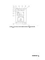
1-4 General Information
Figure 1-1. HP 70900B Local Oscillator Source Front-Panel Features
General Information 1-5
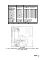
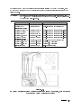
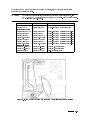
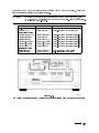
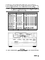
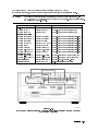
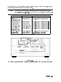
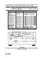
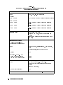
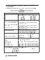
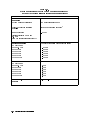
HP 70900B Local Oscillator Source Rear-Panel Features
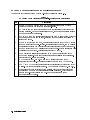
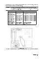
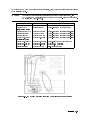
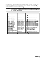
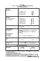
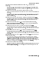
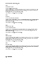
The numbers in the \Item" column of Table 1-2 refer to callouts in Figure 1-2.
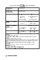
Table 1-2.
HP 70900B Local Oscillator Source Rear-Panel Feature Descriptions
Item
Description
1
300 MHz OUT 1 and 2 provide 300 MHz, 0 dB signals that are used by other
modules in the system for reference and phase-locking.
2
EXT TRIG IN is a TTL input that is used for the external trigger functions of the
spectrum analyzer. When in external trigger mode, the spectrum analyzer begins a
sweep upon receipt of this signal.
3
HSWP IN/OUT has a TTL signal that is high any time the LO is sweeping. This port
works both as an output and an input, allowing other modules in the system to
interrupt the sweep.
4
100 MHz IN receives the 100 MHz, 0 dB signal input that is used by the LO for all
frequency synthesis and phase-locking. If this signal is not present, the LO will use
an internally generated 100 MHz signal which will result in reduced performance.
5
VIDEO IN receives a 0 to 2 V signal input that is the post-detected signal that will
be displayed on the screen. This signal is processed by the LO.
6
SWEEP provides a signal that is a linear 0 to 10 V ramp corresponding to the
sweep of the analyzer. There is no tuning information available from this signal.
It represents the x-axis of the display.
7
LO OUT provides the 3.0 to 6.6 GHz swept LO signal that is used for RF
conversion (heterodyning). The signal amplitude can vary from +7 to 15 dBm.
8
TUNE + SPAN OUT provides a signal that is proportional to the frequency of the
LO signal. The tune span signal varies 1.5 V per GHz with a range of 4.5 to 9.9 V.
9
The mainframe/module interconnect is a multiple-pin connector that plugs into
the mainframe when the module is installed in the mainframe. This connector
provides power-supply voltages and HP-MSIB connections for module
communication and control.
1-6 General Information
Figure 1-2. HP 70900B Local Oscillator Source Rear-Panel Features
General Information 1-7
HP 70900B Local Oscillator Source Options
The HP 70900B local oscillator source has the following module options available.
Option 910 This option adds another set of the user documentation that normally ship
with the module.
Option 915 This option adds the module service documentation and module verication
software.
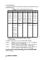
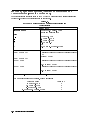
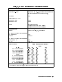
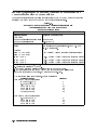
HP 70900B Local Oscillator Source Accessories
The HP 70900B local oscillator source may be ordered separately or as part of an
HP 70000 Series modular spectrum analyzer system. When ordered separately, accessories
are supplied for the most common system congurations. Table 1-3 lists cables included
with the module when ordered separately. When ordered with an HP 70000 Series modular
measurement system, cables are supplied to connect the module in that conguration. Refer to
Chapter 2 for cables available to congure other module arrangements.
Table 1-3. Accessories Shipped When Module is Ordered Separately
Description
Span HP Part Number
Flexible cable, SMB(f) to SMB(f), 9 cm (3.5 in.)
1/8
5061-9015
Flexible cable, SMB(f) to SMB(f), 39 cm (15.4 in.)
7/8
5061-9021
Semirigid LO cable, SMA(m) to SMA(m)
2/8
5021-5449
Flexible LO cable, SMA(m) to SMA(m), 52 cm (20 in.) N/A
5061-9038
1-8 General Information
Preparing an HP 70000 System for Use
System Operating Requirements
Refer to Chapter 3 for the following information:
operating and storage temperature ranges
weights and dimensions of each system or module
power requirements of the HP 70001A mainframe or HP 70004A color display
Before running the HP 11990A system performance test software, refer to \System Calibration
Certication" for warm-up requirement information.
DANGER
Before turning the system on, make sure it is grounded through the
protective conductor of the power cable to a socket outlet with
protective earth contact. Any interruption of the protective (grounding)
conductor inside or outside the instrument, or disconnection of the
protective earth terminal, can result in personal injury.
Before turning the system on, be sure the line voltage selector is set to
the correct voltage for the power source. Failure to do this may cause
damage (a blown fuse) to the system when the power cable is plugged
in.
Do not operate a 400 Hz Option instrument on a 400 Hz power line
without the attached in-line isolation transformer. Failure to follow this
precaution can result in personal injury.
General Information 1-9
Initial System Power-On
The HP 70000 Series modular spectrum analyzer system is shipped as a precongured system
model (for example, HP 71100C modular spectrum analyzer), with most rear panel inter-module
cables connected. (Some cables are removed for shipping.) The following procedure may be
used to ensure that proper initial conditions exist at power-on.
1. Locate the cables shipped with the system.
2. Inspect socket ends and cables for damage.
3. If the loose inter-module cables are intact, connect them. For information on rear panel
cabling examples, refer to Chapter 2. Make sure each rear panel inter-module cable is
connected securely.
4. Make sure the system line-voltage selectors are set to the same voltage as the power source.
5. Connect the power cables to the instruments rst, then plug the cables into the power
outlet.
6. If the LO module is located in the HP 70004A color display, perform the steps below in the
order shown. If the LO module is located in the HP 70001A mainframe, perform Step b rst
and then Step a.
a. Set the HP 70001A mainframe line switch to the on position and listen to verify that the
ventilation fan starts up.
b. Set the HP 70004A color display line switch to the on position and listen to verify that
the ventilation fan starts up.
7. Observe that the indicator lights ash on the front panels of each module. (Refer to
\HP 70900B Local Oscillator Source Front-Panel Features".)
8. Check to see that the STATUS indicator light labeled ACT on the modules in the selected
system remain lit. When two IF sections are in the system, only the one that is selected will
have its ACTive light on.
If the system responds properly, make sure that the system is allowed to warm-up before
running any system verication tests. Refer to \System Calibration Certication" and Chapter 3
for warm-up time requirements.
System Calibration Certication
To qualify a modular spectrum analyzer for calibration certication, allow the instrument
to warm up for at least 1 hour, then load and run the HP 11990A system performance test
software. The HP 11990A system performance test software is available through your local
Hewlett-Packard sales or service oces.
If all tests pass, a certication label may be applied to the front panel of the modular spectrum
analyzer system. The certication label indicates that the system has met certain specications.
All test routines must be passed before the system can qualify for a certication label. The
customer's own label may be applied, or an Hewlett-Packard service oce may perform the
calibration and apply a Hewlett-Packard certication label to the front panel of the system.
1-10 General Information
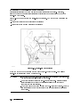
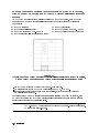
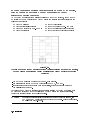
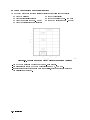
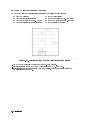
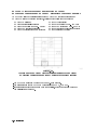
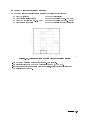
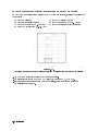
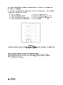
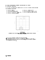
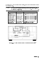
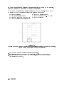
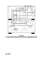
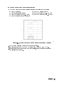
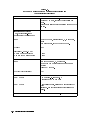
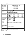
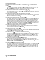
Instrument Keypad for a Spectrum Analyzer
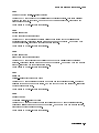
A spectrum analyzer instrument keypad (see Figure 1-3) is shipped with each HP 70900B local
oscillator source. This keypad, designed to plug into the front of an HP 70004A color display,
allows the operator to access or activate spectrum analyzer control functions from the front of
the HP 70004A color display. The spectrum analyzer instrument keypad can be used with the
current LO module and HP 70004A color display rmware.
Each spectrum analyzer control function is enabled by pressing the function key that controls
that function. Once enabled, the function (along with its current data value) is displayed both
in the active function area of the display and outside the graticule border. To change the value
of the active function use the display's data knob, step keys, or numeric keyboard. Table 1-4
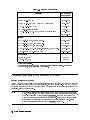
lists the function keys that are on the spectrum analyzer instrument keypad.
Refer to the HP 70000 Modular Spectrum Analyzer Operating Manual or the HP 70004A Color
Display User's Guide for additional information.
Function Key
CENTER5
4
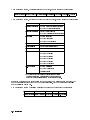
Table 1-4. Instrument Keypad Function Keys
Description of Function
Activates the center frequency function, which can then be tuned
continuously over the range of the spectrum analyzer using the data
controls.
SPAN5
Changes the total display frequency range symmetrically about the center
frequency.
REF LEVEL5
Changes the absolute amplitude power or voltage represented by the top
graticule on the screen.
4
4
START FREQ5 Sets the frequency at the left side of the graticule.
4STOP FREQ5
Sets the frequency at the right side of the graticule.
4SIGNAL TRACK5 Allows the analyzer to automatically maintain drifting signals at the
4
center of the screen. As the signal drifts, the spectrum analyzer is retuned
to bring the signal and marker to the center of the screen. This allows
real-time monitoring of the change.
NORMAL5
4
Activates a frequency marker at the center of the screen on the active
trace. The data controls are used to position the marker. An annotation in
the active function area and in the upper-right corner indicate the
frequency and amplitude of the marker.
PEAK SEARCH5 Places a marker on the highest peak.
415
Provides a means of nding and displaying the frequency and amplitude
4
dierences (delta) between the two signals with the highest amplitude.
NEXT PEAK5 Places the marker on the next highest peak.
4SAVE5
Saves the spectrum analyzer states to the state registers.
4RECALL5
Retrieves spectrum analyzer states from the state registers.
4
General Information 1-11
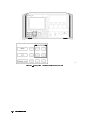
Figure 1-3. Spectrum Analyzer Instrument Keypad
1-12 General Information
System Rack-Mount and Cabinet Interconnect Installation
To make bench operation of the system easier, HP 70000 Series modular measurement system
mainframes and stand-alone models (for example, HP 70206A system graphics display) have
fold-away tilt stands and plastic feet that are designed to be self-aligning when systems are
stacked. Use the following information when modifying your system for rack-mounting or
when connecting two system cabinets.
CAUTION
Be sure to use the correct hardware when replacing parts. Both Metric and
English hardware are used with these instruments. Using incorrect screw sizes
may damage the instrument cabinet.
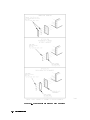
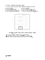
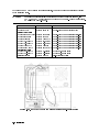
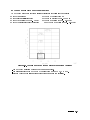
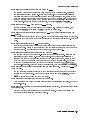
Rack-Mounting
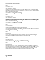
Front handles must be removed before installing system rack-mounting options. Refer to
Figure 1-4.
CAUTION
Do not rack mount multiple mainframes or stand-alone models with one
rack-mount hardware kit. One rack-mount hardware kit must be ordered for
each stand-alone model or mainframe.
System Option 908, rack ange kit without handles, and System Option 913, rack ange kit
with handles, contain the necessary hardware for mounting the HP 70004A color display and
the HP 70001A mainframe.
Figure 1-4 provides rack-mount option screw sizes, and handle or bracket-positioning for proper
rack-mount installation. Angle brackets (HP 12679C) may be ordered to provide the additional
rear or side support required of a mounted instrument.
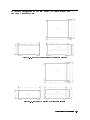
Rack-Mounting with Slides
System Option 810, rack mount with slides is for a system with an HP 70004A color display and
an HP 70001A mainframe. This option contains the necessary hardware to attach slides to both
the display and the mainframe and mount them in a rack.
System Option 811, Rack Mount with Slides is for a system with an HP 70206A system graphics
display stand-alone display and an HP 70001A mainframe. This option contains the necessary
hardware to attach slides to both the stand-alone display and the mainframe and mount them
in a rack.
Table 2-3 identies the part numbers of slide rack-mount kits. Installation instructions are
included with each kit.
General Information 1-13
Figure 1-4. Front Handle Removal and Rack Mounting
1-14 General Information
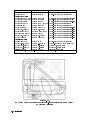
Interconnecting Instrument Cabinets
CAUTION
The HP 70001A mainframe and HP 70206A system graphics display use Metric
4.0 screws. Other System II cabinets use Metric 3.5 or English 6-32 screws.
Using incorrect screw sizes may damage the instrument cabinet.
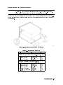
Kit hardware used for vertically interconnecting System II cabinets is illustrated in Figure 1-5.
The kit contains both Metric and English screws to cover all mainframe and System II cabinet
combinations.
Figure 1-5. Interconnecting System II Cabinets
Qty
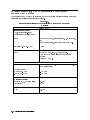
Table 1-5. Interconnect Hardware
Description
HP Part Number
CD
HP 70001A mainframe to HP 70001A mainframe
interlock kit (HP part number 70001-60059, CD = 9)
2 Front Tie Link
1600-0367
7
2 Rear Tie Link
70001-00037
7
4 M4 X 6L Screw
0515-0898
7
HP 70001A mainframe to System II cabinet
interlock kit (HP part number 5061-9061, CD = 6)
4 Front Tie Link
1600-0367
7
2 Rear Tie Link
70001-00036
6
4 M4 X 6L Screw
0515-0898
7
10 M3.5 X 6L Screw
0515-0887
4
10 #6-32 X 3/166 Screw 2360-0330
5
General Information 1-15
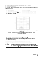
Line Voltage Selection
Use the line-voltage selectors to select the appropriate voltage setting for each mainframe or
display in the system. The line-voltage selector is located on the bottom of the mainframe, on
the rear panel of the stand-alone display, or on the right side of the HP 70004A color display.
See Figure 1-6.
DANGER
Before turning the system on, make sure it is grounded through the
protective conductor of the power cable to a socket outlet with
protective earth contact. Any interruption of the protective (grounding)
conductor inside or outside the instrument, or disconnection of the
protective earth terminal, can result in personal injury.
Before turning the system on, be sure the line voltage selector is set to
the correct voltage for the power source. Failure to do this may cause
damage (a blown fuse) to the system when the power cable is plugged
in.
Do not operate a 400 Hz Option instrument on a 400 Hz power line
without the attached in-line isolation transformer. Failure to follow this
precaution can result in personal injury.
Figure 1-6. Line Voltage Selector
1-16 General Information
400 Hz Option for the Mainframe and Stand-Alone Display
Both the HP 70001A mainframe and the HP 70206A system graphics display are available with
an option that allows them to run on a power-line frequency of 400 Hz.
Note
The HP 70004A color display does not require an option to operate on 400 Hz.
The modular spectrum analyzer 400 Hz Options come with an external in-line isolation
transformer for use with a 400 Hz power source. Refer to \System Replaceable Parts" in
Chapter 2 for specic option number information. For 400 Hz Option specications, refer to
Chapter 3.
DANGER
Before turning the system on, make sure it is grounded through the
protective conductor of the power cable to a socket outlet with
protective earth contact. Any interruption of the protective (grounding)
conductor inside or outside the instrument, or disconnection of the
protective earth terminal, can result in personal injury.
Before turning the system on, be sure the line voltage selector is set to
the correct voltage for the power source. Failure to do this may cause
damage (a blown fuse) to the system when the power cable is plugged
in.
Do not operate a 400 Hz Option instrument on a 400 Hz power line
without the attached in-line isolation transformer. Failure to follow this
precaution can result in personal injury.
The in-line isolation transformer must be removed from the 400 Hz Option for 60 Hz
power-source operation. Failure to remove the in-line transformer may result in a blown fuse.
When the isolation transformer is removed, a standard power cord must be used. Reinstall the
in-line isolation transformer for use with a 400 Hz power source. This protects the user from
shock hazard.
General Information 1-17
System Line Fuse Replacement
The system line fuse is in the line-module housing, which is located at the rear of the system
mainframe and the display. The Metric 6.3 A fuse (HP part number 2110-0703) can be used
with both 120 V and 230 V power sources. A spare fuse is included with the line fuse in the
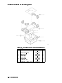
line-module housing. Figure 1-7 illustrates removal and replacement of the system line fuse.
Figure 1-7. Line Fuse Removal and Replacement
1-18 General Information
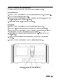
Optional Mainframe Rear-Fan Filter
An optional rear-fan lter may be ordered for the HP 70001A mainframe. This lter is
not included as part of the standard system. Refer to Figure 1-8 for the part number and
installation information for the rear-fan lter.
Figure 1-8. Rear-Fan Filter Installation
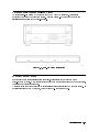
System Power Cables
In accordance with international safety standards, this instrument is equipped with a
three-wire power cable. When this cable is connected to a properly grounded power receptacle,
the instrument cabinet is grounded.
A suitable cable for systems shipped to international customers is included with each system. If
additional cables need to be ordered, refer to Figure 1-9 for part numbers.
General Information 1-19
Figure 1-9. AC Power Cords
1-20 General Information
Display Screen Cleaning
To avoid damaging the coating on the display screen, use a thin lm cleaner such as
Hewlett-Packard Display Cleaner (HP part number 8500-2163). This should be used with an
abrasion-free cleaning tissue or soft cloth.
CAUTION
Do not use hand or laboratory paper towels to clean the display screen. These
abrasive materials may scratch the screen coating. (Refer to \Display Screen
Cleaning".)
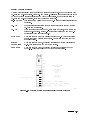
External Power Pack for the HP 70310A Precision Frequency
Reference
An external power pack (see Figure 1-10) provides standby power for the oscillator oven in
the HP 70310A precision frequency reference when the mainframe is o. If an HP 70310A
Option 002 precision frequency reference is ordered, the ovenized oscillator and accessory
power pack are deleted. For the placement of the accessory power pack on the system
mainframe, refer to \System Congurations for \A" and \C" Systems" in Chapter 2.
Figure 1-10. External Power Pack
General Information 1-21
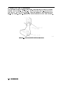
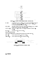
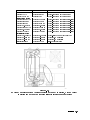
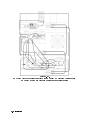
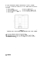
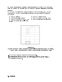
Preparing a Static-Safe Work Station
Electrostatic discharge (ESD) can damage or destroy electronic components. Therefore,
all work performed on assemblies consisting of electronic components should be done at a
static-safe work station.
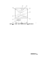
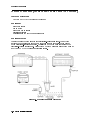
Figure 1-11 shows an example of a static-safe work station. Two types of ESD protection are
shown:
a conductive table mat and wrist strap combination
a conductive oor mat and heel strap combination
Figure 1-11. Static-Safe Work Station
These two types of ESD protection must be used together. Refer to Table 1-6 for a list of
static-safe accessories and their HP part numbers.
CAUTION
Do not touch the edge-connector contacts or trace surfaces with bare hands.
Always handle board assemblies by the edges.
Do not use erasers to clean the edge-connector contacts. Erasers generate
static electricity and degrade the electrical quality of the contacts by
removing the thin gold plating.
Do not use paper of any kind to clean the edge-connector contacts. Paper or
lint particles left on the contact surface can cause intermittent electrical
connections.
1-22 General Information
Preparing a Static-Safe Work Station
Reducing ESD Damage
To help reduce the amount of ESD damage that occurs during testing and servicing use the
following guidelines:
Be sure that all instruments are properly earth-grounded to prevent buildup of static charge.
Personnel should be grounded with a resistor-isolated wrist strap before touching the center
pin of any connector and before removing any assembly from a piece of equipment.
Use a resistor-isolated wrist strap that is connected to the HP 70000 Series modular spectrum
analyzer system mainframe's chassis. If you do not have a resistor-isolated wrist strap, touch
the chassis frequently to equalize any static charge.
Before connecting any coaxial cable to an instrument connector for the rst time each day,
momentarily short the center and outer conductors of the cable together.
Handle all PC board assemblies and electronic components only at static-safe work stations.
Store or transport PC board assemblies and electronic components in static-shielding
containers.
PC board assembly edge-connector contacts may be cleaned by using a lintfree cloth with a
solution of 80% electronics-grade isopropyl alcohol and 20% deionized water. This procedure
should be performed at a static-safe work station.
Static-Safe ESD Accessories
HP Part
Number
Table 1-6. Static-Safe ESD Accessories
Description
9300-0797
Set includes: 3M static control mat 0.6 m 2 1.2 m (2 ft 2 4 ft) and 4.6 m
(15 ft) ground wire. (The wrist-strap and wrist-strap cord are not included.
They must be ordered separately.)
9300-0865
Ground wire, 4.6 m (15 ft)
9300-0980
Wrist-strap cord 1.5 m (5 ft)
9300-1383
Wrist-strap, color black, stainless steel, without cord, has four adjustable
links and a 7 mm post-type connection.
9300-1169
ESD heel-strap (reusable 6 to 12 months).
Order the above by calling HP DIRECT at (800) 538-8787 or through any Hewlett-Packard
Sales and Service Oce.
General Information 1-23
If You Need to Contact Hewlett-Packard
Before calling Hewlett-Packard or returning your instrument, please read your warranty
information. Warranty information is printed at the front of this document.
In any correspondence or telephone conversations, refer to the instrument by its full model
number and full serial number. With this information, the Hewlett-Packard representative can
determine whether your unit is still within its warranty period.
Determining Your Instrument's Serial Number
When a module is manufactured by Hewlett-Packard, it is given a unique serial number. This
serial number is attached to a label on the front frame or front panel of the module. A serial
number label is in two parts. (Refer to Figure 1-12.)
The rst part makes up the serial number prex and consists of four digits and a letter. The
second part makes up the serial number sux and consists of the last ve digits on the serial
number label. The serial number prex is the same for all identical modules; it only changes
when a change in the electrical or physical functionality is made. The serial number sux,
however, changes sequentially and is dierent for each module.
Figure 1-12. Typical Serial Number Label
1-24 General Information
If You Need to Contact Hewlett-Packard
Table 1-7. Hewlett-Packard Sales and Service Oces
US FIELD OPERATIONS EUROPEAN OPERATIONS
HEADQUARTERS
HEADQUARTERS
INTERCON OPERATIONS
HEADQUARTERS
California
Australia
Hewlett-Packard Company
19320 Pruneridge Avenue
Cupertino, CA 95014, USA
(800) 752-0900
Hewlett-Packard S.A.
150, Route du Nant-d'Avril
1217 Meyrin 2/Geneva
Switzerland
(41 22) 780.8111
Hewlett-Packard Co.
France
1421 South Manhattan Ave. Hewlett-Packard France
Fullerton, CA 92631
1 Avenue Du Canada
(714) 999-6700
Zone D'Activite De Courtaboeuf
F-91947 Les Ulis Cedex
Hewlett-Packard Co.
France
301 E. Evelyn
(33 1) 69 82 60 60
Mountain View, CA 94041
(415) 694-2000
Germany
Hewlett-Packard GmbH
Colorado
Hewlett-Packard-Strasse
Hewlett-Packard Co.
61352 Bad Homburg
24 Inverness Place, East
Germany
Englewood, CO 80112
(+49 6172) 16-0
(303) 649-5000
Georgia
Hewlett-Packard Co.
2124 Barrett Park Drive
Kennesaw, GA 30144
(404) 955-1500
Illinois
Hewlett-Packard Co.
5201 Tollview Drive
Rolling Meadows, IL 60008
(708) 342-2000
New Jersey
Hewlett-Packard Co.
150 Green Pond Road
Rockaway, NJ 07866
(201) 586-5400
Texas
Hewlett-Packard Co.
930 E. Campbell Rd.
Richardson, TX 75081
(214) 231-6101
Great Britain
Hewlett-Packard Company
3495 Deer Creek Rd.
Palo Alto, California 94304-1316
(415) 857-5027
Hewlett-Packard Australia Ltd.
31-41 Joseph Street (P.O. Box 221)
Blackburn, Victoria 3130
(61 3) 895-2895
Canada
Hewlett-Packard (Canada) Ltd.
17500 South Service Road
Trans-Canada Highway
Kirkland, Quebec H9J 2X8
Canada
(514) 697-4232
Japan
Yokogawa-Hewlett-Packard Ltd.
Hewlett-Packard Ltd.
1-27-15 Yabe, Sagamihara
Eskdale Road, Winnersh Triangle Kanagawa 229, Japan
Wokingham, Berkshire RG11 5DZ (81 427) 59-1311
England
(44 734) 696622
China
China Hewlett-Packard, Co.
38 Bei San Huan X1 Road
Shuang Yu Shu
Hai Dian District
Beijing, China
(86 1) 256-6888
Singapore
Hewlett-Packard Singapore
Pte. Ltd.
Alexandra P.O. Box 87
Singapore 9115
(65) 271-9444
Taiwan
Hewlett-Packard Taiwan
8th Floor, H-P Building
337 Fu Hsing North Road
Taipei, Taiwan
(886 2) 712-0404
General Information 1-25
Returning Your Instrument to Hewlett-Packard
Hewlett-Packard has sales and service oces around the world to provide complete support for
your instrument. To obtain servicing information or to order replacement parts, contact the
nearest Hewlett-Packard sales and service oce listed in Table 1-7.
Use the following procedure to return your instrument to Hewlett-Packard:
1. Fill out a service tag (available at the end of this document) and attach it to the instrument.
Please be as specic as possible about the nature of the problem. Send a copy of any or all
of the following information:
any error messages that appeared on the HP 70000 Series display
a completed Performance Test record
any other specic data on the performance of the instrument
CAUTION
Damage can result if the original packaging materials are not used. Packaging
materials should be anti-static and should cushion the instrument on all sides.
Never use styrene pellets in any shape as packaging materials. They do not
adequately cushion the instrument or prevent it from moving in the shipping
container. Styrene pellets can also cause equipment damage by generating
static electricity or by lodging in fan motors.
2. Place the instrument in its original packaging materials.
If the original packaging materials are not available, you can contact a Hewlett-Packard
sales and service oce to obtain information on packaging materials or you may use an
alternative packing material referred to as \bubble-pack". One of the companies that makes
bubble-pack is Sealed Air Corporation of Hayward, California, 94545.
3. Surround the instrument with at least 3 to 4 inches of its original packing material or
bubble-pack to prevent the instrument from moving in its shipping container.
4. Place the instrument, after wrapping it with packing material, in its original shipping
container or a strong shipping container that is made of double-walled corrugated cardboard
with 159 kg (350 lb) bursting strength.
The shipping container must be both large enough and strong enough to accommodate your
instrument and allow at least 3 to 4 inches on all sides for packing material.
5. Seal the shipping container securely with strong nylon adhesive tape.
6. Mark the shipping container \FRAGILE, HANDLE WITH CARE" to help ensure careful
handling.
7. Retain copies of all shipping papers.
1-26 General Information
Returning Your Instrument to Hewlett-Packard
Table 1-8. Packaging for a 1/8 Module (Instrument)
Item Description HP Part Number Qty
1
2
3
4
5
Carton-outer
Carton-inner
Carton-sliders
Foam inserts
Foam pads
5180-8479
9211-4781
5180-2369
4208-0493
5180-8469
1
1
1
2
2
General Information 1-27
Returning Your Instrument to Hewlett-Packard
Table 1-9. Packaging for a 2/8 Module (Instrument)
Item Description HP Part Number Qty
1
2
3
4
5
1-28 General Information
Carton-outer
Carton-inner
Carton-sliders
Foam inserts
Foam pads
5180-8479
9211-4781
5180-2369
4208-0493
5180-8469
1
1
1
1
2
Returning Your Instrument to Hewlett-Packard
Table 1-10. Packaging for a 3/8 Module (Instrument)
Item Description HP Part Number Qty
1
2
3
4
Carton-outer
Carton-inner
Carton-sliders
Foam pads
5180-8479
9211-4781
5180-2369
5180-8469
1
1
1
2
General Information 1-29
Returning Your Instrument to Hewlett-Packard
Table 1-11. Packaging for an 8/8 Module (Instrument)
Item
Description
HP Part Number Qty
1
2
3
4
5
6
7
8
1-30 General Information
Corrugated Carton (Top)
Foam Corner-Pads
Flat End-Cap
Static Sheet
Front Cover
Foam Plastic
Corrugated Pad
Corrugated Carton (Outer)
9211-6785
5040-6967
9220-4962
9222-1806
5040-6974
4208-1210
9220-5072
9211-7065
1
8
1
1
1
1
1
1
2
Installation
This chapter contains information necessary for installing the components of an
HP 70000 Series modular spectrum analyzer system. The factory ships HP 70000 Series modular
spectrum analyzer systems with all system components installed and addressed. All cables,
however, are subject to removal for shipment.
The following information is included in this chapter.
\HP-MSIB/HP-IB Addressing" provides information for setting the HP-MSIB address of each
module, explains how HP-IB and HP-MSIB addresses interrelate, and illustrates examples of
address switches.
\Module Removal and Installation" describes how to remove or install modules.
\System Congurations for \A" and \C" Systems" give examples of common system
congurations. The information given in each example includes an HP-MSIB address map, a
listing of cables needed, and cable connection information.
\System Replaceable Parts" lists model and HP part numbers for system-level replaceable
parts, system cables, and service accessories.
HP-MSIB/HP-IB Addressing
An element in an HP 70000 Series modular measurement system is a system component able
to communicate with other modules over HP-MSIB. Element addresses must adhere to the set
of rules dened in this section.
HP-MSIB addressing is dierent from HP-IB addressing, and is explained in more detail in this
section. The topics listed below include denitions and information about the HP-MSIB and
HP-IB address of an element. Correct addressing requires an understanding of the following
concepts:
Modular Measurement System Terms
Address Map (Matrix) Protocol
Addressing Elements
Addressing Order Requirements
Address Switches
Installation 2-1
Modular Measurement System Terms
Understanding the following terms is essential to understanding HP-MSIB addressing and the
structural relationship of modular measurement system devices.
Functional Terms
The devices of a modular system may be combined in such a way to allow them to
communicate and operate as an instrument. The following terms identify the interrelationship
among devices within a modular instrument.
Element
Any device that communicates over the HP-MSIB (for example,
HP 70902A IF section). In contrast, the HP 70001A mainframe controls
all HP-MSIB communication, but does not communicate over the
HP-MSIB and therefore is not an element.
Master
An element that controls other elements.
Sub-master
An element that simultaneously controls other elements and is
controlled by another element.
Slave
An element that is controlled by another element.
Independent element An element that is neither a master nor a slave (for example,
HP 70004A color display).
Instrument
A module, or group of modules, that performs an independent function
(for example, HP 71100C modular spectrum analyzer).
Structural Terms
Modular systems consist of hardware structures dedicated to specic functions. The structural
terms used in reference to these functions are described below.
Mainframe
A housing for modules which also provides power, cooling,
interconnection for HP-MSIB and HP-IB, and HP-MSIB communications
control for up to eight 1/8-width modules. The HP 70004A color display
also provides the same functions for up to four 1/8-width modules.
Module
Modules are devices that plug into an HP 70001A mainframe or
HP 70004A color display. Modules cannot function without these
independent elements.
Stand-Alone
An HP-MSIB element capable of performing its functions without a
mainframe or HP 70004A color display (for example, HP 70206A system
Instrument
graphics display).
2-2 Installation
Address Map Protocol
Protocol for master, sub-master, slave, and independent element addressing is explained in this
section. The factors governing proper system communication and system function are based on
adherence to the addressing protocol of modular spectrum analyzers.
By denition, a master is an element addressed to control another element, or is the controlling
element of a system. Slave elements are addressed within the area a master controls, called the
slave area. Independent elements are addressed so that they are neither masters nor slaves,
though they may have functions that appear to control other elements. For example, the
graphics display front panel keys are used to select LO functions, but the LO is not a slave to
the display.
Address Matrix
The address matrix is a graphic representation of assigned and available HP-MSIB addresses.
The address assigned to each element appears on the matrix and indicates the relationship
among master, sub-master, slave, and independent elements. Module function, access to HP-IB
communication, and error reporting are all based on the location of the module address on
the matrix. See Figure 2-1. The 8-row by 32-column matrix implies that 256 addresses are
available; however, there are actually 255 legal addresses plus an illegal address at row 0,
column 31.
Figure 2-1. Address Matrix
Each element must have a unique 8-bit binary HP-MSIB address correctly placed on the
address matrix. The three most signicant bits (MSB) determine the row address; the ve least
signicant bits (LSB), the column address. This manual refers to the decimal equivalent of a
binary address.
Table 2-1. Decimal Equivalent of Binary Address
Row Column
MSB LSB
Binary 010 11000
Decimal 2
24
Installation 2-3
Display-Response Area
NNNNNNNNNNNNNNNNNNNNNNNNNNNNNNNNNNNNNNNNN
A display-response area exists at row 0. The display's REPORT ERRORS menu key function can
only access a module addressed at row 0. A display must be assigned to an instrument before
communication between the two is initiated. This can be done automatically or manually. The
automatic assignment function ( SELECT INSTRUMENT menu key) searches the display-response
area (row 0) when it assigns itself to an instrument. The display can be assigned to a module at
any other row, but this assignment must be done manually using the ASSIGN KEYBOARD and
ASSIGN WINDOW menu keys.
NNNNNNNNNNNNNNNNNNNNNNNNNNNNNNNNNNNNNNNNNNNNNNNNNNNNN
NNNNNNNNNNNNNNNNNNNNNNNNNNNNNNNNNNNNNNNNNNNNNNN
NNNNNNNNNNNNNNNNNNNNNNNNNNNNNNNNNNNNNNNNN
Note
To be addressed at row 0, a module must be designed to interface with the
display and report errors. If a module that does not have these capabilities is
addressed at row 0, the system will cease to communicate.
HP-IB Access
The HP-IB access area is at row 0 of the address matrix. Address row 0, column 31, however, is
an illegal address location for any element. Modules that have been designed for HP-IB access
are able to use HP-IB only if their addresses are in the HP-IB access area (row 0, columns 0
through 30).
Note
Address row 0, column 31 is an illegal address for any element.
Addressing Elements
Master Elements
The address switches set an element's HP-MSIB address. If the element is a master or an
independent element, the column switches also determine the default HP-IB address. (Displays
do not have row address switches, so they are always set to row address 0.) A master is
typically placed at any legal row 0 address. This row address location allows error reporting
and access to HP-IB. If neither error reporting nor HP-IB access are required, a master may be
placed at any legal address.
Modules controlled by another module are called slaves. To be controlled by a master, slave
modules must be addressed within the slave area dened by that master. Refer to Figure 2-2
for examples of modules in a slave area. For proper system function and communication, slaves
must be addressed within the boundaries set by the dening elements.
A dening element is any element, residing to the right and in the same row or lower than a
master.
2-4 Installation
Sub-Master Elements
Figure 2-2. Master/Slave Address Matrix
A sub-master is an element that can function as both master and slave at the same time.
Sub-masters are located at a row address other than 0, are controlled by another master, and
control a slave area of their own. For example, Figure 2-3 illustrates sub-master M2 at address
3, 24. M2 is a slave to M1. M2 also has a slave area that lies within the slave area of M1. M1
does not communicate directly with M2 slaves; it can only communicate with them through M2.
Slave Elements
Figure 2-3. Sub-Master Address Matrix
For an instrument to function properly, the master must determine the slave area it controls on
the address matrix. Master modules establish their slave area by determining the location of
the dening element on the address matrix. The dening element establishes the boundaries of
the slave area. Any module located within this area is a slave to the master module.
Installation 2-5
The HP-MSIB address requirements of a dening element are as follows:
The column address of a dening element must be greater than the column address of the
master. In Figure 2-2, for the master addressed in column 23, the dening element must be
addressed in column 24 or above. In Figure 2-3, for M2 addressed in column 24, the dening
element must be addressed in column 25 or above.
The row address of a dening element must be equal to or less than the row address of a
master. In Figure 2-2 the address of the master at row 0 has a dening element addressed at
row 0. Figure 2-3 shows two masters, M1 and M2. The dening element for M1 is located at
row 0 and the dening element for M2 is located at row 3.
Slave Area Boundaries
The master determines its slave-area boundaries by rst searching upward in its own column
starting in the master's row, then in each higher column starting in the master's row. The
search stops at the boundary column or, if there is no dening element, after searching column
31.
After a master locates the dening element of its slave area, the slave area boundaries are set
by using the following criteria:
The column address of the master is the left-hand boundary of the slave area. In Figure 2-2,
the left-hand boundary is column 23.
The right-hand boundary of the slave area is equal to one less than the column address of
the dening element. For the master at column 23 in Figure 2-2, the right-hand boundary
is at column 28. If there is no dening element, the right-hand boundary of the slave area
extends through column 31.
The lower boundary of the slave area is one row greater than the row address of the master.
For the master in row 0 in Figure 2-2, the lower boundary is at row 1.
The upper boundary of the slave area is the top row of the matrix (row 7).
If a new module is added to the area labeled \No Element Present" in Figure 2-2, this module
becomes the new dening element and the right-hand boundary moves toward the master.
Independent Elements
An independent element, such as a display, is neither a master nor a slave. Displays are
considered independent elements and separate instruments. Because they do not have row
address switches, displays automatically are at row address 0. The typical address for a display
is row 0, column 4.
2-6 Installation
Addressing Order Requirements for HP 70000 Systems
HP-MSIB addresses are set by switches located on each module. The address consists of two
parts: a row number and a column number. A module's address can be determined by viewing
the address map or selecting the conguration screen.
Measurement systems are composed of more than one module. When this is true, the modules
will assume master/slave relationships to simplify the user interface. Each master has specic
slave addressing requirements and expectations.
The HP 70900B local oscillator source is the master of many possible spectrum analyzer system
congurations. It will automatically congure itself into a system with the slaves that it nds
available in its slave area on the address map. It searches for these slaves with a specic
pattern and expects to nd them in a certain order.
The HP 70900B local oscillator source searches the address map by starting in the column
where it is addressed and looking for a module in the row directly above it. It continues to
look up that column row by row until it reaches the top. It then moves to the next column
to the right. Again, it begins its search at the row above its own location, searching up the
column to the top. It continues this process until it has searched its entire slave area. In this
way it identies the slave modules that it will congure into a system. For a more detailed
description of how a master's slave area is dened, refer to \Address Map Protocol".
Default Addressing for Congured HP 70000 Systems
Default addresses have been set up to allow for current and future addressing considerations.
The use of these default addresses will permit adding additional modules to a system with a
minimum of address manipulation. Individual modules shipped from the factory will have their
HP-MSIB address set as dened in the default address map. Table 2-2 lists the location of the
current modules in the default address map.
Table 2-2. Default Address Map
Row
7
blank
HP 70310
blank
6
RF sections
HP 70300
y HP 70620 or HP 70621
5
HP 70907
HP 70301
blank
4
HP 70903
blank
HP 70810B Option 850
3
HP 70911
* HP 70620 or HP 70621
HP 70810B
2
HP 70700
HP 70600 or HP 70601
blank
1
HP 70902
blank
blank
0
HP 70900
blank
blank
column 18
column 19
column 20
* When preamplifying the preselector's or RF section's input signal.
y When preamplifying the lightwave section's input signal.
Installation 2-7
Addressing Criteria
Each module, or type of module, has addressing criteria that impact address selection. The
descriptions below are written as if the modules are in the same column; however, this is not a
requirement as long as their relative position is maintained with respect to the HP 70900B local
oscillator source search pattern.
HP 70900B local oscillator A single HP 70900B local oscillator source master module may
source
control only 16 slave modules.
HP 70902A IF section
The HP 70902A IF section, if present, must be closest to the
local oscillator (that is, the HP 70902A IF section should be
immediately above the HP 70900B local oscillator source in the
address map. It must be the rst module that the HP 70900B
local oscillator source nds when it searches the slave area.)
HP 70911A WB IF section The HP 70911A WB IF section, if present, should be above the
HP 70900B local oscillator source, HP 70902A IF section, and
the HP 70700A digitizer. It should be below the HP 70903A
IF section, HP 70907A/B external millimeter interface module,
and the RF section. For cabling the HP 70911A WB IF section,
refer to the HP 71910A Wide Bandwidth Surveillance Receiver
User's Guide.
HP 70700A digitizer
When the HP 70700A digitizer is present and used as a slave to
the HP 70900B local oscillator source, it should be addressed
above the HP 70902A IF section (if present). It should also be
addressed below the HP 70903A IF section (if present) and the
HP 70911A WB IF section (if present).
HP 70903A IF section
The HP 70903A IF section, if present, should be above the
HP 70902A IF section. It should be the next module that the
HP 70900B local oscillator source nds when it searches the
slave area. If the HP 70902A IF section is not present, the
HP 70903A IF section should be above the local oscillator. If all
three of the previously mentioned modules are present when
the HP 70900B local oscillator source searches the slave area,
it should nd the HP 70902A IF section, then the HP 70700A
digitizer, and then the HP 70903A IF section.
HP 70907A/B external
An HP 70907A/B external millimeter interface module should
millimeter interface module be addressed immediately below the RF section. Multiple
external mixer interface modules should follow each other in
the addressing order.
RF section
Only one RF Section (HP 70904A RF section, HP 70905A/B
RF section, HP 70906A/B RF section, HP 70908A RF section,
HP 70909A RF section, or HP 70910A RF section) may be used
with a single HP 70900B local oscillator source. The RF section
should be immediately above the IF sections or external mixer
interface module.
HP 70600A preselector/
The HP 70600A preselector/HP 70601A preselector, if present,
HP 70601A preselector
should be immediately above the HP 70905A/B RF section
or HP 70906A/B RF section. It should normally be the next
module that the HP 70900B local oscillator source nds after
the RF section when it searches the slave area.
2-8 Installation
HP 70300A
RF tracking generator
HP 70301A microwave
tracking generator
HP 70310A precision
frequency reference
HP 70810B lightwave
section
HP 70620A/B preamplier
or HP 70621A preamplier
The HP 70300A RF tracking generator should be addressed just
above an HP 70301A microwave tracking generator, if one is
present.
The HP 70301A microwave tracking generator should be
addressed just below an HP 70300A RF tracking generator, if
one is present.
The HP 70310A precision frequency reference may be
addressed anywhere.
The HP 70810B lightwave section should be addressed
above the RF section. It should also be addressed above the
preselector, if one is present.
The HP 70620A/B preamplier or HP 70621A preamplier
should be addressed above the module that it is providing
preamplication for. Multiple preamplier modules may be used
in the same system. When the HP 70900B local oscillator source
searches its slave area, each preamplier must be found above
the module (for example, RF section, preselector, preamplier)
that its output is connected to.
Installation 2-9
Row Addressing Priority
The row addressing priority for systems is shown below. Notice that this order is a relative
row-address ranking only. The individual modules do not require consecutive row addresses
(that is, there can be empty rows between modules). Also, note that all modules need not be in
the same column. They need only fall in the slave area of the master module.
Highest row (last found):
HP 70620A/B preamplier or HP 70621A preamplier (only if preamplifying the lightwave
section's input signal)
HP 70810B Option 850 lightwave section
HP 70810B lightwave section
HP 70310A precision frequency reference
HP 70300A RF tracking generator
HP 70301A microwave tracking generator
HP 70620A/B preamplier or HP 70621A preamplier (if preamplifying the preselector's or
the RF section's input signal)
HP 70600A preselector or HP 70601A preselector
HP 70904A RF section, HP 70905A RF section, HP 70905B RF section HP 70906A RF section,
HP 70906B RF section HP 70908A RF section, HP 70909A RF section, HP 70910A RF section
(one only)
HP 70907A/B external millimeter interface module (several allowed)
HP 70903A IF section
HP 70911A WB IF section
HP 70700A digitizer
HP 70902A IF section
Lowest row (row 0):
HP 70900B local oscillator source
Note
HP-MSIB addresses must be unique. Setting two HP 70000 elements to the
same address will create an error and make the local system bus (HP-MSIB)
inoperative. If the cursor cannot be moved about within the address map after
a module has been readdressed, check to see if two modules have the same
row and column address.
Address Switches
The row and column address switches set the HP-MSIB address of a module; the column
address switch also sets the HP-IB address for masters and independent elements.
To establish proper system function and HP-MSIB communication, each module has an address
switch that is set to a binary, 8-bit HP-MSIB address. Each element in a system must be
assigned a unique address. The row address of the HP-MSIB address is determined by three
address bits, and the column address is determined by ve address bits. Each system has 8
row and 32 column addresses. Address row 0, column 31 is an illegal address; therefore, 255
HP-MSIB addresses are available. The decimal equivalents of the binary row and column
addresses are referred to throughout this manual. For example, see the table below.
2-10 Installation
Binary
Decimal
Row Column
010
2
11000
24
The following three sections describe the address switch functions for each of the elements and
independent elements available.
Master Address Switches
Slave Address Switches
Display Address Switches
The address switches may be found on the top, side, or rear of the modules, and at the rear of
the HP 70004A color display and HP 70206A system graphics display. The location of address
switches is dened in each element's installation and verication manual.
For system addressing and cable conguration examples, refer to \System Congurations for
\A" and \C" Systems".
Master Address Switches
The HP-MSIB column address is the same as the default HP-IB address of a master. It is dened
by the position of the column address switches.
The HP-IB address of any master (for example, HP 70900B local oscillator source) can, under
certain conditions, be set from the front panel of a display. At power-up, this address will
override the actual address switch settings. For additional information on how to set the
HP-IB address from the front panel, refer to HP 70000 Modular Spectrum Analyzer Operating
Manual.
Figure 2-4 is an illustration of address switches found on an HP 70900B local oscillator source.
HP-IB ON/OFF With this switch set to o, the HP 70900B local oscillator source is switched
o the HP-IB and uses only the HP-MSIB for communication.
SW1/MEM
In the SW1 position, the HP-IB address is determined exclusively by the
column address switches. In the MEM position, the HP-IB address is
determined by HP 70900B local oscillator source memory and can be set
from the front panel of the display. The HP 70900B local oscillator source is
normally shipped with this switch in the MEM position.
Installation 2-11
Figure 2-4. HP 70900B Local Oscillator Source Address Switch
MAS/SLA
NRML/TEST
COLUMNs 1|5
ROWs 1|3
With this set to the MAS position, the HP 70900B local oscillator source can
function as a master or sub-master; with it set to the SLA position, the
HP 70900B local oscillator source is a slave.
This switch should be set to NRML for normal operation. The TEST position
is used for a hard reset and during production.
These set the HP-MSIB column address, which is also the default HP-IB
address.
These set the HP-MSIB row address.
Slave Address Switches
Figure 2-5 is an illustration of typical address switches found on a slave element.
Rows 1|3
These switches set the HP-MSIB row address.
Columns 1|5 These switches set the HP-MSIB column address.
Figure 2-5. Slave Element Address Switches
2-12 Installation
Display Address Switches
A system graphics display is an example of an independent element. It may be assigned both
HP-MSIB and HP-IB addresses. Figure 2-6 and Figure 2-7 illustrate the address switches of the
HP 70206A system graphics display and HP 70004A color display. For more information on
HP-MSIB and HP-IB addressing, refer to \Address Map Protocol".
HP-IB ON/OFF This switches the display on or o the HP-IB without disrupting instrument
operation.
A6|A8
The graphical representation of these switches indicates that the default
HP-MSIB row address is 0.
A1|A5
These address switches set the HP-MSIB column address, which is also the
default HP-IB address. (This HP-IB address is overridden when the HP-IB
address is set from the front panel.)
TALK ONLY
When this is set to 1 (on) the display can talk on HP-IB without requiring
a reply, since some plotters cannot reply. This switch is set to 0 (o) for
normal operation.
SYSTEM
When this is set to 1 (on), the display functions as a system controller on
CONTROLLER HP-IB. This switch is set to 0 (o) at the factory.
TEST MODE
When this is set to 1 (on), the display goes into a special test mode at
power-up. This switch is set to 0 (o) for normal operation.
Figure 2-6. HP 70206A System Graphics Display Address Switches
Installation 2-13
Figure 2-7. HP 70004A Color Display Address Switches
2-14 Installation
Module Removal and Installation
The following procedure denes the steps in removing or installing modules.
Module Removal
1. Set the HP 70004A color display/HP 70001A mainframe line switch to o. See Figure 2-8.
2. Remove the rear panel intermodule cables.
3. Open the HP 70004A color display/HP 70001A mainframe front panel door. With an 8 mm
hex-ball driver, loosen the module hex-nut latch.
4. Press against the rear panel, and slide the module out.
Installation
1. Set the HP 70004A color display/HP 70001A mainframe line switch to o.
2. Check the HP-MSIB address switch on the module for the correct address setting.
3. Open the HP 70004A color display/HP 70001A mainframe front panel door, and slide the
module into the HP 70004A color display/HP 70001A mainframe.
4. Press against the module front panel while tightening the hex-nut latch with an 8 mm
hex-ball driver.
5. Connect the rear panel intermodule cables as shown in the \System Conguration"
examples.
6. Turn the HP 70004A color display/HP 70001A mainframe line switch on.
Figure 2-8. Module Removal/Replacement
Installation 2-15
WARNING If an instrument handle is damaged it should be replaced immediately.
Damaged handles can break while the instrument is being moved or lifted.
This may cause damage to the instrument or personal injury.
Connecting the MSIB Cables on a \A" and \C" System
Figure 2-9. HP 70001A Mainframe to HP 70004A Color Display Cabling
2-16 Installation
Connecting the MSIB Y-Cable on a \P" System
CAUTION
Care should be taken when connecting the MSIB Y-cable to the
MSIB interface card. Damage can occur if the MSIB Y-cable connection is
not properly aligned. Ensure power is not applied while making or removing
connections.
1. Remove the protective cap from the MSIB Y-cable and inspect the pins for damage or
misalignment. Do not install MSIB Y-cable if pins are bent or damaged. If
necessary, obtain service from Hewlett-Packard. Refer to \If You Need to Contact
Hewlett-Packard" in Chapter 1.
2. Align the MSIB Y-cable to the MSIB interface card's MSIB connector (1).
Do not force the connectors together! (See the above caution.)
3. Tighten the captive-screws on the MSIB Y-cable to the MSIB interface card.
Do not over tighten the screws!
4. Connect the two free-ends of the MSIB Y-cable (that are not connected to the
MSIB interface card) to the HP 70001A mainframe's IN and OUT MSIB connectors (2).
The MSIB cables are connected serially, coupling the input of one HP 70001A
mainframe to the output of the next until a loop is completed.
5. Connect the ac line cord to your computer and display.
Note
Refer to the HP 70207A User's Guide for complete installation instructions of
the HP 70207A PC Display for MMS, the MSIB interface card, and the MSIB
Y-cable.
Installation 2-17
System Congurations for \A" and \C" Systems
The gures in this section show the addressing order and cable connections for some
common \A" and \C" system congurations. The following information is provided for each
conguration.
A sample address map screen illustrating the addressing order.
A partial view of the system rear panel illustrating cable connections.
Modules included in the system to ensure that needed elements are available.
A list of rear panel cables describing type, quantity, and HP part numbers.
A from-to list describing where to connect the cables and adapters.
These gures are examples. To address a system dierently than shown, refer to
\HP-MSIB/HP-IB Addressing". Modules can be congured in any location, provided the
cables are connected to the correct inputs and outputs. The suggested congurations are
recommended for optimum instrument speed and minimum changes when adding modules. The
system conguration examples provided in this section are listed below.
2-18 Installation
\A" and \C" System Conguration Examples
HP 71100C modular spectrum analyzer:
Standard
Standard with HP 70903A IF section added
Standard with HP 70700A digitizer added
Standard with HP 70903A IF section and
HP 70700A digitizer added
Standard with HP 70300A RF tracking generator added
Figure 2-11
Figure 2-13
Figure 2-15
Figure 2-17
Figure 2-19
HP 71200C modular spectrum analyzer:
Standard
Standard with HP 70903A IF section added
Standard deleting HP 70902A IF section, with HP 70903A IF section
and HP 70907A external millimeter interface module (EMIM) added
Standard deleting HP 70905A RF section, with HP 70905B RF section
and HP 70600A preselector added
Standard deleting HP 70905A RF section, with HP 70905B RF section,
HP 70600A preselector and HP 70301A microwave tracking generator
added
Figure 2-21
Figure 2-23
Figure 2-25
Figure 2-27
Figure 2-29
HP 71209A microwave spectrum analyzer:
Standard
Figure 2-31
HP 71210C microwave spectrum analyzer:
Standard
Figure 2-33
HP 71400C lightwave signal analyzer:
Standard
Standard with HP 70300A RF tracking generator and
HP 70301A microwave tracking generator added
Figure 2-35
Figure 2-37
HP 71401C lightwave signal analyzer:
Standard
Standard with HP 70300A RF tracking generator added
Figure 2-39
Figure 2-41
Installation 2-19
HP 71100C Modular Spectrum Analyzer
An HP 71100C modular spectrum analyzer consists of the following components:
HP 70001A mainframe
HP 70900B local oscillator source
HP 70904A RF section (100 Hz { 2.9 GHz)
HP 70004A color display
HP 70902A IF section (10 Hz { 300 KHz)
HP 70310A precision frequency reference
Figure 2-10. Address Map for HP 71100C Modular Spectrum Analyzer
The HP 70001A mainframe does not have an HP-MSIB address.
The usual address for the HP 70004A color display is ROW 0, COLUMN 4.
For information about software/rmware compatibility, refer to \Software/Hardware
Compatibility" in Chapter 4.
2-20 Installation
To congure an HP 71100C modular spectrum analyzer, connect the rear panel cables according
to the following table.
CAUTION
To ensure proper electrical connection and prevent connector damage, all
APC 3.5 and SMA connectors must be torqued 5 to 8 inch-pounds (nger tight).
Do not exceed 8 inch-pounds.
From
Flexible LO I/O Cables
To
Cable
HP 70900B LO OUT
HP 70904A 1st LO IN
HP 5061-9038 520 mm SMA(m) to SMA(m)
HP 70900B 300 MHZ OUT 1
HP 70900B 100 MHZ IN
HP 70900B VIDEO IN
HP 70904A 21.4 MHz OUT
HP 70904A 300 MHZ IN
HP 70310A 100 MHZ
HP 70902A VIDEO OUT
HP 70902A 21.4 MHz IN
HP 8120-5022
HP 8120-5022
HP 8120-5016
HP 8120-5022
HP 70001A HP-MSIB OUT
HP 70004A HP-MSIB OUT
External Power Pack
HP 70004A HP-MSIB IN HP 70800B 1.0 m MSIB cable
HP 70001A HP-MSIB IN HP 70800B 1.0 m MSIB cable
HP 70310A EXT PWR
Built-in Power Pack Cable
Flexible System Cables
Miscellaneous Cables
365 mm
365 mm
160 mm
365 mm
SMB(f) to SMB(f) (6-slot)
SMB(f) to SMB(f) (6-slot)
SMB(f) to SMB(f) (2-slot)
SMB(f) to SMB(f) (6-slot)
Figure 2-11. HP 71100C Modular Spectrum Analyzer Rear Panel Cabling
Installation 2-21
HP 71100C Modular Spectrum Analyzer with HP 70903A IF Section
An HP 71100C modular spectrum analyzer with HP 70903A IF section, consists of the following
components:
HP 70001A mainframe
HP 70900B local oscillator source
HP 70902A IF section (10 Hz { 300 KHz)
HP 70904A RF section (100 Hz { 2.9 GHz)
HP 70004A color display
HP 70903A IF section (100 KHz { 3 MHz)
HP 70310A precision frequency reference
Figure 2-12.
Address Map for HP 71100C Modular Spectrum Analyzer with HP 70903A IF Section
The HP 70001A mainframe does not have an HP-MSIB address.
The usual address for the HP 70004A color display is ROW 0, COLUMN 4.
For information about software/rmware compatibility, refer to \Software/Hardware
Compatibility" in Chapter 4.
2-22 Installation
To congure an HP 71100C modular spectrum analyzer with HP 70903A IF section, connect the
rear panel cables according to the following table.
CAUTION
To ensure proper electrical connection and prevent connector damage, all
APC 3.5 and SMA connectors must be torqued 5 to 8 inch-pounds (nger tight).
Do not exceed 8 inch-pounds.
From
Flexible LO I/O Cables
To
Cable
HP 70900B LO OUT
HP 70904A 1st LO IN
HP 5061-9038 520 mm SMA(m) to SMA(m)
HP 70900B 300 MHZ OUT 1
HP 70900B 100 MHZ IN
HP 70900B VIDEO IN
HP 70904A 21.4 MHz OUT
HP 70902A 21.4 MHz IN
HP 70902A VIDEO OUT
HP 70904A 300 MHZ IN
HP 70310A 100 MHZ
HP 70903A VIDEO OUT
HP 70903A 21.4 MHz IN
HP 70903A 21.4 MHz OUT
HP 70903A VIDEO IN
HP 8120-5022
HP 8120-5022
HP 8120-5016
HP 8120-5022
HP 8120-5014
HP 8120-5014
HP 70001A HP-MSIB OUT
HP 70004A HP-MSIB OUT
External Power Pack
HP 70004A HP-MSIB IN
HP 70001A HP-MSIB IN
HP 70310A EXT PWR
HP 70800B 1.0 m MSIB cable
HP 70800B 1.0 m MSIB cable
Built-in Power Pack Cable
Flexible System Cables
Miscellaneous Cables
365 mm
365 mm
160 mm
365 mm
100 mm
100 mm
SMB(f) to SMB(f) (6-slot)
SMB(f) to SMB(f) (6-slot)
SMB(f) to SMB(f) (2-slot)
SMB(f) to SMB(f) (6-slot)
SMB(f) to SMB(f) (1-slot)
SMB(f) to SMB(f) (1-slot)
Figure 2-13.
HP 71100C Modular Spectrum Analyzer Rear Panel Cabling with HP 70903A IF Section
Installation 2-23
HP 71100C Modular Spectrum Analyzer with HP 70700A Digitizer
An HP 71100C modular spectrum analyzer with HP 70700A digitizer consists of the following
components:
HP 70001A mainframe
HP 70900B local oscillator source
HP 70904A RF section (100 Hz { 2.9 GHz)
HP 70700A digitizer
HP 70004A color display
HP 70902A IF section (10 Hz { 300 KHz)
HP 70310A precision frequency reference
Figure 2-14.
Address Map for HP 71100C Modular Spectrum Analyzer with HP 70700A Digitizer
The HP 70001A mainframe does not have an HP-MSIB address.
The usual address for the HP 70004A color display is ROW 0, COLUMN 4.
For information about software/rmware compatibility, refer to \Software/Hardware
Compatibility" in Chapter 4.
2-24 Installation
To congure an HP 71100C modular spectrum analyzer with HP 70700A digitizer as a slave,
connect the rear panel cables according the following table. Note that the HP-IB switch on the
HP 70700A digitizer must be in the o position.
CAUTION
To ensure proper electrical connection and prevent connector damage, all
APC 3.5 and SMA connectors must be torqued 5 to 8 inch-pounds (nger tight).
Do not exceed 8 inch-pounds.
From
Flexible LO I/O Cables
To
Cable
HP 70900B LO OUT
HP 70904A 1st LO IN
HP 5061-9038 520 mm SMA(m) to SMA(m)
HP 70900B 300 MHZ OUT 1
HP 70900B 100 MHZ IN
HP 70904A 21.4 MHz OUT
HP 70900B VIDEO IN
* HP 70700A INPUT 2
HP 70900B HSWP IN/OUT
* HP 70700A HI SWP
HP 70700A CLK IN
HP 70904A 300 MHZ IN
HP 70310A 100 MHZ
HP 70902A 21.4 MHz IN
* HP 70700A INPUT 2
HP 70902A VIDEO OUT
* HP 70700A HI SWP
HP 70700A EXT TRIG
HP 70700A CLK OUT
HP 8120-5022
HP 8120-5022
HP 8120-5022
HP 8120-5016
HP 8120-5014
HP 8120-5016
HP 8120-5014
HP 8120-5014
Flexible System Cables
Miscellaneous Cables
365 mm
365 mm
365 mm
160 mm
100 mm
160 mm
100 mm
100 mm
SMB(f) to SMB(f) (6-slot)
SMB(f) to SMB(f) (6-slot)
SMB(f) to SMB(f) (6-slot)
SMB(f) to SMB(f) (2-slot)
SMB(f) to SMB(f) (1-slot)
SMB(f) to SMB(f) (2-slot)
SMB(f) to SMB(f) (1-slot)
SMB(f) to SMB(f) (1-slot)
HP 70001A HP-MSIB OUT HP 70004A HP-MSIB IN HP 70800B 1.0 m MSIB cable
HP 70004A HP-MSIB OUT HP 70001A HP-MSIB IN HP 70800B 1.0 m MSIB cable
Built-in Power Pack Cable
HP 70310A EXT PWR
External Power Pack
* On this connector, use an HP 1250-1391 50
SMB tee(f) (m) (m) adapter.
Figure 2-15.
HP 71100C Modular Spectrum Analyzer Rear Panel Cabling with HP 70700A Digitizer
Installation 2-25
HP 71100C Modular Spectrum Analyzer with HP 70903A IF Section and
HP 70700A Digitizer
An HP 71100C modular spectrum analyzer with HP 70903A IF section and HP 70700A digitizer
consists of the following components:
HP 70001A mainframe
HP 70900B local oscillator source
HP 70903A IF section (100 KHz { 3 MHz)
HP 70310A precision frequency reference
HP 70004A color display
HP 70902A IF section (10 Hz { 300 KHz)
HP 70904A RF section (100 Hz { 2.9 GHz)
HP 70700A digitizer
Figure 2-16.
Address Map for HP 71100C Modular Spectrum Analyzer with HP 70903A IF Section and
HP 70700A Digitizer
The HP 70001A mainframe does not have an HP-MSIB address.
The usual address for the HP 70004A color display is ROW 0, COLUMN 4.
For information about software/rmware compatibility, refer to \Software/Hardware
Compatibility" in Chapter 4.
To congure an HP 71100C modular spectrum analyzer with HP 70903A IF section and
HP 70700A digitizer as a slave, connect the rear panel cables according to the following table.
Note that the HP-IB switch on the HP 70700A digitizer should be in the o position.
CAUTION
2-26 Installation
To ensure proper electrical connection and prevent connector damage, all
APC 3.5 and SMA connectors must be torqued 5 to 8 inch-pounds (nger tight).
Do not exceed 8 inch-pounds (nger tight).
From
Flexible LO I/O Cables
To
Cable
HP 70900B LO OUT
HP 70904A 1st LO IN
HP 5061-9038 520 mm SMA(m) to SMA(m)
HP 70900B 300 MHZ OUT 1
HP 70900B 100 MHZ IN
HP 70900B VIDEO IN
* HP 70700A INPUT 2
HP 70900B HSWP IN/OUT
* HP 70700A HI SWP
HP 70904A 21.4 MHz OUT
HP 70902A VIDEO OUT
HP 70902A 21.4 MHz IN
HP 70700A CLK IN
HP 70904A 300 MHZ IN
HP 70310A 100 MHZ
* HP 70700A INPUT 2
HP 70903A VIDEO OUT
* HP 70700A HI SWP
HP 70700A EXT TRIG
HP 70903A 21.4 MHz IN
HP 70903A VIDEO IN
HP 70903A 21.4 MHz OUT
HP 70700A CLK OUT
HP 8120-5022
HP 8120-5022
HP 8120-5016
HP 8120-5021
HP 8120-5016
HP 8120-5014
HP 8120-5016
HP 8120-5014
HP 8120-5014
HP 8120-5014
Flexible System Cables
Miscellaneous Cables
365 mm
365 mm
160 mm
310 mm
160 mm
100 mm
160 mm
100 mm
100 mm
100 mm
SMB(f) to SMB(f) (6-slot)
SMB(f) to SMB(f) (6-slot)
SMB(f) to SMB(f) (2-slot)
SMB(f) to SMB(f) (5-slot)
SMB(f) to SMB(f) (2-slot)
SMB(f) to SMB(f) (1-slot)
SMB(f) to SMB(f) (2-slot)
SMB(f) to SMB(f) (1-slot)
SMB(f) to SMB(f) (1-slot)
SMB(f) to SMB(f) (1-slot)
HP 70001A HP-MSIB OUT HP 70004A HP-MSIB IN
HP 70800B 1.0 m MSIB cable
HP 70004A HP-MSIB OUT HP 70001A HP-MSIB IN
HP 70800B 1.0 m MSIB cable
External Power Pack
HP 70310A EXT PWR
Built-in Power Pack Cable
* On this connector, use an HP 1250-1391 50
SMB tee(f) (m) (m) adapter.
Figure 2-17.
HP 71100C Modular Spectrum Analyzer Rear Panel Cabling with HP 70903A IF Section
and HP 70700A Digitizer
Installation 2-27
HP 71100C Modular Spectrum Analyzer with HP 70300A
RF Tracking Generator
An HP 71100C modular spectrum analyzer with an HP 70300A RF tracking generator consists
of the following components:
HP 70001A mainframe
HP 70900B local oscillator source
HP 70904A RF section (100 Hz { 2.9 GHz)
HP 70300A RF tracking generator
HP 70004A color display
HP 70902A IF section (10 Hz { 300 KHz)
HP 70310A precision frequency reference
Figure 2-18.
Address Map for HP 71100C Modular Spectrum Analyzer with HP 70300A
RF Tracking Generator
The HP 70001A mainframe does not have an HP-MSIB address.
The usual address for the HP 70004A color display is ROW 0, COLUMN 4.
For information about software/rmware compatibility, refer to \Software/Hardware
Compatibility" in Chapter 4.
To congure an HP 71100C modular spectrum analyzer with an HP 70300A
RF tracking generator, connect the rear panel cables according to the following table.
CAUTION
2-28 Installation
To ensure proper electrical connection and prevent connector damage, all
APC 3.5 and SMA connectors must be torqued 5 to 8 inch-pounds (nger tight).
Do not exceed 8 inch-pounds.
From
Flexible LO I/O Cables
To
Cable
HP 70900B LO OUT
HP 70904A 1st LO IN
HP 5061-9038 520 mm SMA(m) to SMA(m)
HP 70900B 300 MHZ OUT 1
HP 70900B 300 MHZ OUT 2
HP 70900B 100 MHZ IN
HP 70900B TUNE SPAN
HP 70900B SWEEP
HP 70900B VIDEO IN
HP 70904A 21.4 MHz OUT
HP 70900B HSWP IN/OUT
HP 70904A 300 MHZ IN
HP 70300A 300 MHZ IN
HP 70310A 100 MHZ
HP 70300A TUNE + SPAN
HP 70300A SWEEP IN
HP 70902A VIDEO OUT
HP 70902A 21.4 MHz IN
HP 70300A RF tracking generator HSWP IN
HP 8120-5022
HP 8120-5025
HP 8120-5022
HP 8120-5025
HP 8120-5025
HP 8120-5016
HP 8120-5022
HP 8120-5025
HP 70904A 1st LO OUT
HP 70300A 0-2.9 GHZ OUT
HP 70001A HP-MSIB OUT
HP 70004A HP-MSIB OUT
External Power Pack
HP 70300A LO IN
HP 70300A 0-2.9 GHZ IN
HP 70004A HP-MSIB IN
HP 70001A HP-MSIB IN
HP 70310A EXT PWR
HP 5021-5495 400 mm SMA(m) to SMA(m)
HP 70300-20067 380 mm SMA(m) to SMA(m)
HP 70800B 1.0 m MSIB cable
HP 70800B 1.0 m MSIB cable
Built-in Power Pack Cable
Flexible System Cables
Miscellaneous Cables
365 mm
490 mm
365 mm
490 mm
490 mm
160 mm
365 mm
490 mm
SMB(f) to SMB(f) (6-slot)
SMB(f) to SMB(f)
SMB(f) to SMB(f) (6-slot)
SMB(f) to SMB(f)
SMB(f) to SMB(f)
SMB(f) to SMB(f) (2-slot)
SMB(f) to SMB(f) (6-slot)
SMB(f) to SMB(f)
Figure 2-19.
HP 71100C Modular Spectrum Analyzer Rear Panel Cabling with an HP 70300A
RF Tracking Generator
Installation 2-29
HP 71200C Modular Spectrum Analyzer
An HP 71200C modular spectrum analyzer consists of the following components:
HP 70001A mainframe
HP 70900B local oscillator source
HP 70905A RF section (50 KHz { 22 GHz)
HP 70004A color display
HP 70902A IF section (10 Hz { 300 KHz)
HP 70310A precision frequency reference
Figure 2-20. Address Map for HP 71200C Modular Spectrum Analyzer
The HP 70001A mainframe does not have an HP-MSIB address.
The usual address for the HP 70004A color display is ROW 0, COLUMN 4.
For information about software/rmware compatibility, refer to \Software/Hardware
Compatibility" in Chapter 4.
2-30 Installation
To congure an HP 71200C modular spectrum analyzer, connect the rear panel cables according
to the following table.
CAUTION
To ensure proper electrical connection and prevent connector damage, all
APC 3.5 and SMA connectors must be torqued 5 to 8 inch-pounds (nger tight).
Do not exceed 8 inch-pounds.
From
Flexible LO I/O Cables
To
Cable
HP 70900B LO OUT
HP 70905A 1st LO IN
HP 5061-9038 520 mm SMA(m) to SMA(m)
HP 70900B 300 MHZ OUT 1
HP 70900B 100 MHZ IN
HP 70900B VIDEO IN
HP 70905A 21.4 MHz OUT
HP 70905A 300 MHZ IN
HP 70310A 100 MHZ
HP 70902A VIDEO OUT
HP 70902A 21.4 MHz IN
HP 8120-5022
HP 8120-5022
HP 8120-5016
HP 8120-5022
HP 70905A 321.4 MHZ OUT
HP 70001A HP-MSIB OUT
HP 70004A HP-MSIB OUT
External Power Pack
HP 70905A 321.4 MHZ IN
HP 70004A HP-MSIB IN
HP 70001A HP-MSIB IN
HP 70310A EXT PWR
HP 70905-20024 55 mm SMA(m) to SMA(m)
HP 70800B 1.0 m MSIB cable
HP 70800B 1.0 m MSIB cable
Built-in Power Pack Cable
Flexible System Cables
Miscellaneous Cables
365 mm
365 mm
160 mm
365 mm
SMB(f) to SMB(f) (6-slot)
SMB(f) to SMB(f) (6-slot)
SMB(f) to SMB(f) (2-slot)
SMB(f) to SMB(f) (6-slot)
Figure 2-21. HP 71200C Modular Spectrum Analyzer Rear Panel Cabling
Installation 2-31
HP 71200C Modular Spectrum Analyzer with HP 70903A IF Section
An HP 71200C modular spectrum analyzer with HP 70903A IF section, consists of the following
components:
HP 70001A mainframe
HP 70900B local oscillator source
HP 70903A IF section (100 KHz { 3 MHz)
HP 70310A precision frequency reference
HP 70004A color display
HP 70902A IF section (10 Hz { 300 KHz)
HP 70905A RF section (50 KHz { 22 GHz)
Figure 2-22.
Address Map for HP 71200C Modular Spectrum Analyzer with HP 70903A IF Section
The HP 70001A mainframe does not have an HP-MSIB address.
The usual address for the HP 70004A color display is ROW 0, COLUMN 4.
For information about software/rmware compatibility, refer to \Software/Hardware
Compatibility" in Chapter 4.
2-32 Installation
To congure an HP 71200C modular spectrum analyzer with an HP 70903A IF section, connect
the rear panel cables according to the following table.
CAUTION
To ensure proper electrical connection and prevent connector damage, all
APC 3.5 and SMA connectors must be torqued 5 to 8 inch-pounds (nger tight).
Do not exceed 8 inch-pounds.
From
Flexible LO I/O Cables
To
Cable
HP 70900B LO OUT
HP 70905A 1st LO IN
HP 5061-9038 520 mm SMA(m) to SMA(m)
HP 70900B 300 MHZ OUT 1
HP 70900B 100 MHZ IN
HP 70900B VIDEO IN
HP 70905A 21.4 MHz OUT
HP 70902A VIDEO OUT
HP 70902A 21.4 MHz IN
HP 70905A 300 MHZ IN
HP 70310A 100 MHZ
HP 70903A VIDEO OUT
HP 70903A 21.4 MHz IN
HP 70903A VIDEO IN
HP 70903A 21.4 MHz OUT
HP 8120-5022
HP 8120-5022
HP 8120-5016
HP 8120-5022
HP 8120-5014
HP 8120-5014
HP 70905A 321.4 MHZ OUT
HP 70001A HP-MSIB OUT
HP 70004A HP-MSIB OUT
External Power Pack
HP 70905A 321.4 MHZ IN
HP 70004A HP-MSIB IN
HP 70001A HP-MSIB IN
HP 70310A EXT PWR
HP 70905-20024 55 mm SMA(m) to SMA(m)
HP 70800B 1.0 m MSIB cable
HP 70800B 1.0 m MSIB cable
Built-in Power Pack Cable
Flexible System Cables
Miscellaneous Cables
365 mm
365 mm
160 mm
365 mm
100 mm
100 mm
SMB(f) to SMB(f) (6-slot)
SMB(f) to SMB(f) (6-slot)
SMB(f) to SMB(f) (2-slot)
SMB(f) to SMB(f) (6-slot)
SMB(f) to SMB(f) (1-slot)
SMB(f) to SMB(f) (1-slot)
Figure 2-23.
HP 71200C Modular Spectrum Analyzer Rear Panel Cabling with HP 70903A IF Section
Installation 2-33
HP 71200C Modular Spectrum Analyzer Deleting HP 70902A IF Section,
with HP 70903A IF Section and HP 70907B External Millimeter Interface
Module
An HP 71200C modular spectrum analyzer deleting HP 70902A IF section, with HP 70903A
IF section and HP 70907B external millimeter interface module consists of the following
components:
HP 70001A mainframe
HP 70900B local oscillator source
HP 70905A RF section (50 KHz { 22 GHz)
HP 70907B external millimeter interface module
HP 70004A color display
HP 70903A IF section (100 KHz { 3 MHz)
HP 70310A precision frequency reference
Figure 2-24.
Address Map for HP 71200C Modular Spectrum Analyzer Deleting HP 70902A IF Section,
with HP 70903A IF Section and HP 70907B External Millimeter Interface Module
The HP 70001A mainframe does not have an HP-MSIB address.
The usual address for the HP 70004A color display is ROW 0, COLUMN 4.
For information about software/rmware compatibility, refer to \Software/Hardware
Compatibility" in Chapter 4.
To congure an HP 71200C modular spectrum analyzer deleting HP 70902A IF section, with
HP 70903A IF section and HP 70907B external millimeter interface module connect the rear
panel cables according to the following table.
CAUTION
2-34 Installation
To ensure proper electrical connection and prevent connector damage, all
APC 3.5 and SMA connectors must be torqued 5 to 8 inch-pounds (nger tight).
Do not exceed 8 inch-pounds.
From
Flexible LO I/O Cables
To
Cable
HP 70900B LO OUT
HP 70905A 1ST LO OUT
HP 70905A 1st LO IN
HP 70907B LO IN
HP 5061-9038 520 mm SMA(m) to SMA(m)
HP 5021-5448 150 mm SMA(m) to SMA(m)
HP 70900B 300 MHZ OUT 1
HP 70900B 100 MHZ IN
HP 70900B VIDEO IN
HP 70905A 21.4 MHz OUT
HP 70900B 300 MHZ OUT 2
HP 70907B 21.4 MHz OUT
HP 70900B TUNE SPAN
HP 70905A 300 MHZ IN
HP 70310A 100 MHZ
HP 70903A VIDEO OUT
HP 70907B 21.4 MHz IN
HP 70907B 300 MHZ IN
HP 70903A 21.4 MHz IN
HP 70907B TUNE SPAN
HP 8120-5022
HP 8120-5022
HP 8120-5016
HP 8120-5016
HP 8120-5022
HP 8120-5022
HP 8120-5022
HP 70905A 321.4 MHZ OUT
HP 70001A HP-MSIB OUT
HP 70004A HP-MSIB OUT
External Power Pack
HP 70905A 321.4 MHZ IN
HP 70004A HP-MSIB IN
HP 70001A HP-MSIB IN
HP 70310A EXT PWR
HP 70905-20024 55 mm SMA(m) to SMA(m)
HP 70800B 1.0 m MSIB cable
HP 70800B 1.0 m MSIB cable
Built-in Power Pack Cable
Flexible System Cables
Miscellaneous Cables
365 mm
365 mm
160 mm
160 mm
365 mm
365 mm
365 mm
SMB(f) to SMB(f) (6-slot)
SMB(f) to SMB(f) (6-slot)
SMB(f) to SMB(f) (2-slot)
SMB(f) to SMB(f) (2-slot)
SMB(f) to SMB(f) (6-slot)
SMB(f) to SMB(f) (6-slot)
SMB(f) to SMB(f) (6-slot)
Figure 2-25.
HP 71200C Modular Spectrum Analyzer Deleting HP 70902A IF Section, with HP 70903A
IF Section and HP 70907B External Millimeter Interface Module Cabling
Installation 2-35
HP 71200C Modular Spectrum Analyzer Deleting HP 70905A RF Section,
with HP 70905B RF Section/HP 70600A Preselector
An HP 71200C modular spectrum analyzer deleting HP 70905A RF section, with HP 70905B
RF section/HP 70600A preselector consists of the following components:
HP 70001A mainframe
HP 70900B local oscillator source
HP 70905B RF section (50 KHz { 22 GHz)
HP 70310A precision frequency reference
HP 70004A color display
HP 70902A IF section (10 Hz { 300 KHz)
HP 70600A preselector
Figure 2-26.
Address Map for HP 71200C Modular Spectrum Analyzer Deleting HP 70905A RF Section,
with HP 70905B RF Section/HP 70600A Preselector
The HP 70001A mainframe does not have an HP-MSIB address.
The usual address for the HP 70004A color display is ROW 0, COLUMN 4.
For information about software/rmware compatibility, refer to \Software/Hardware
Compatibility" in Chapter 4.
2-36 Installation
To congure an HP 71200C modular spectrum analyzer deleting HP 70905A RF section, with
HP 70905B RF section/HP 70600A preselector connect the rear panel cables according to the
following table.
CAUTION
To ensure proper electrical connection and prevent connector damage, all
APC 3.5 and SMA connectors must be torqued 5 to 8 inch-pounds (nger tight).
Do not exceed 8 inch-pounds.
From
Flexible LO I/O Cables
To
Cable
HP 70900B LO OUT
HP 70905A 1st LO IN
HP 5061-9038 520 mm SMA(m) to SMA(m)
HP 70900B 300 MHZ OUT 1
HP 70900B 100 MHZ IN
HP 70900B VIDEO IN
HP 70905B 21.4 MHz OUT
HP 70900B TUNE SPAN
HP 70905B 300 MHZ IN
HP 70310A 100 MHZ
HP 70902A VIDEO OUT
HP 70902A 21.4 MHz IN
HP 70600A TUNE SPAN
HP 8120-5022
HP 8120-5022
HP 8120-5016
HP 8120-5022
HP 8120-5022
HP 70905B 321.4 MHZ OUT
HP 70001A HP-MSIB OUT
HP 70004A HP-MSIB OUT
External Power Pack
HP 70905B 321.4 MHZ IN
HP 70004A HP-MSIB IN
HP 70001A HP-MSIB IN
HP 70310A EXT PWR
HP 70905-20024 55 mm SMA(m) to SMA(m)
HP 70800B 1.0 m MSIB cable
HP 70800B 1.0 m MSIB cable
Built-in Power Pack Cable
Flexible System Cables
Miscellaneous Cables
365 mm
365 mm
160 mm
365 mm
365 mm
SMB(f) to SMB(f) (6-slot)
SMB(f) to SMB(f) (6-slot)
SMB(f) to SMB(f) (2-slot)
SMB(f) to SMB(f) (6-slot)
SMB(f) to SMB(f) (6-slot)
Figure 2-27.
HP 71200C Modular Spectrum Analyzer Deleting HP 70905A RF Section, with HP 70905B
RF Section/HP 70600A Preselector Cabling
Installation 2-37
HP 71200C Modular Spectrum Analyzer Deleting HP 70905A RF Section,
with HP 70905B RF Section/HP 70600A Preselector/HP 70301A
Microwave Tracking Generator
An HP 71200C modular spectrum analyzer deleting HP 70905A RF section, with HP 70905B
RF section/HP 70600A preselector/HP 70301A microwave tracking generator consists of the
following components:
HP 70001A mainframe
HP 70900B local oscillator source
HP 70905B RF section (50 KHz { 22 GHz)
HP 70600A preselector
HP 70004A color display
HP 70902A IF section (10 Hz { 300 KHz)
HP 70310A precision frequency reference
HP 70301A microwave tracking generator
Figure 2-28.
Address Map for HP 71200C Modular Spectrum Analyzer Deleting HP 70905A RF Section,
with HP 70905B RF Section/HP 70600A Preselector/HP 70301A Microwave Tracking
Generator
The HP 70001A mainframe does not have an HP-MSIB address.
The usual address for the HP 70004A color display is ROW 0, COLUMN 4.
For information about software/rmware compatibility, refer to \Software/Hardware
Compatibility" in Chapter 4.
To congure an HP 71200C modular spectrum analyzer deleting HP 70905A RF section, with
HP 70905B RF section/HP 70600A preselector/HP 70301A microwave tracking generator,
connect the cables according to the following table.
CAUTION
2-38 Installation
To ensure proper electrical connection and prevent connector damage, all
APC 3.5 and SMA connectors must be torqued 5 to 8 inch-pounds (nger tight).
Do not exceed 8 inch-pounds.
From
Flexible LO I/O Cables
To
Cable
HP 70900B LO OUT
HP 70905B 1ST LO OUT
HP 70905B 1st LO IN
HP 70301A LO IN
HP 5061-9038 520 mm SMA(m) to SMA(m)
HP 5021-5494 400 mm SMA(m) to SMA(m)
HP 70900B 300 MHZ OUT 1
HP 70900B 100 MHZ IN
HP 70900B VIDEO IN
HP 70905B 21.4 MHz OUT
HP 70900B TUNE SPAN
* HP 70301A TUNE SPAN
HP 70900B 300 MHZ OUT 2
HP 70301A 21.4 MHz IN
HP 70905A 300 MHZ IN
HP 70310A 100 MHZ
HP 70902A VIDEO OUT
HP 70902A 21.4 MHz IN
* HP 70301A TUNE SPAN
HP 70600A TUNE SPAN
HP 70301A 300 MHZ IN
HP 70301A 21.4 MHz OUT
HP 8120-5022
HP 8120-5022
HP 8120-5016
HP 8120-5022
HP 8120-5025
HP 8120-5022
HP 8120-5025
HP 8120-5014
Flexible System Cables
Miscellaneous Cables
365 mm
365 mm
160 mm
365 mm
490 mm
365 mm
490 mm
100 mm
SMB(f) to SMB(f) (6-slot)
SMB(f) to SMB(f) (6-slot)
SMB(f) to SMB(f) (2-slot)
SMB(f) to SMB(f) (6-slot)
SMB(f) to SMB(f)
SMB(f) to SMB(f) (6-slot)
SMB(f) to SMB(f)
SMB(f) to SMB(f) (1-slot)
HP 70905B 321.4 MHZ OUT HP 70905B 321.4 MHZ IN HP 70905-20024 55 mm SMA(m) to SMA(m)
HP 70001A HP-MSIB OUT HP 70004A HP-MSIB IN
HP 70800B 1.0 m MSIB cable
HP 70004A HP-MSIB OUT HP 70001A HP-MSIB IN
HP 70800B 1.0 m MSIB cable
External Power Pack
HP 70310A EXT PWR
Built-in Power Pack Cable
* On this connector, use an HP 1250-1391 50
SMB tee(f) (m) (m) adapter.
Figure 2-29.
HP 71200C Modular Spectrum Analyzer Deleting HP 70905A RF Section, with HP 70905B
RF Section/HP 70600A Preselector/HP 70301A Microwave Tracking Generator Cabling
Note
The HP 71201A Option 001 modular spectrum analyzer uses this same
cabling conguration, but contains the HP 70906B RF section in place of
the HP 70905B RF section and the HP 70601A preselector in place of the
HP 70600A preselector.
Installation 2-39
HP 71209A Microwave Spectrum Analyzer
An HP 71209A microwave spectrum analyzer consists of the following components:
HP 70001A mainframe
HP 70900B local oscillator source
HP 70903A IF section (100 KHz { 3 MHz)
HP 70310A precision frequency reference
HP 70004A color display
HP 70902A IF section (10 Hz { 300 KHz)
HP 70909A RF section (100 Hz { 26.5 GHz)
or HP 70910A RF section (100 Hz { 26.5 GHz)
Figure 2-30. Address Map for HP 71209A Microwave Spectrum Analyzer
The HP 70001A mainframe does not have an HP-MSIB address.
The usual address for the HP 70004A color display is ROW 0, COLUMN 4.
Refer to Chapter 1 for information about software/rmware compatibility.
2-40 Installation
To congure an HP 71209A microwave spectrum analyzer, connect the rear panel cables
according to the following table.
CAUTION
To ensure proper electrical connection and prevent connector damage, all
APC 3.5 and SMA connectors must be torqued 5 to 8 inch-pounds (nger tight).
Do not exceed 8 inch-pounds.
Rear-Panel Cable Connections
From
Flexible LO I/O Cables
To
Cable
HP 70900B LO OUT
HP 70909A 1st LO IN
HP 5061-9038 520 mm SMA(m) to SMA(m)
HP 70900B 300 MHZ OUT 1
HP 70900B 100 MHZ IN
HP 70900B VIDEO IN
HP 70909A 21.4 MHz OUT
HP 70900B TUNE SPAN
HP 70902A VIDEO OUT
HP 70902A 21.4 MHz IN
HP 70909A 300 MHZ IN
HP 70310A 100 MHZ
HP 70903A VIDEO OUT
HP 70903A 21.4 MHz IN
HP 70909A TUNE SPAN
HP 70903A VIDEO IN
HP 70903A 21.4 MHz OUT
HP 8120-5022
HP 8120-5022
HP 8120-5016
HP 8120-5022
HP 8120-5022
HP 8120-5014
HP 8120-5014
HP 70001A HP-MSIB OUT
HP 70004A HP-MSIB OUT
External Power Pack
HP 70004A HP-MSIB IN
HP 70001A HP-MSIB IN
HP 70310A EXT PWR
HP 70800B 1.0 m MSIB cable
HP 70800B 1.0 m MSIB cable
Built-in Power Pack Cable
Flexible System Cables
Miscellaneous Cables
365 mm
365 mm
160 mm
365 mm
365 mm
100 mm
100 mm
SMB(f) to SMB(f) (6-slot)
SMB(f) to SMB(f) (6-slot)
SMB(f) to SMB(f) (2-slot)
SMB(f) to SMB(f) (6-slot)
SMB(f) to SMB(f) (6-slot)
SMB(f) to SMB(f) (1-slot)
SMB(f) to SMB(f) (1-slot)
Figure 2-31. HP 71209A Microwave Spectrum Analyzer Rear Panel Cabling
Installation 2-41
HP 71210C Microwave Spectrum Analyzer
An HP 71210C microwave spectrum analyzer consists of the following components:
HP 70001A mainframe
HP 70900B local oscillator source
HP 70903A IF section (100 KHz { 3 MHz)
HP 70310A precision frequency reference
HP 70004A color display
HP 70902A IF section (10 Hz { 300 KHz)
HP 70908A RF section (100 Hz { 22 GHz)
Figure 2-32. Address Map for HP 71210C Microwave Spectrum Analyzer
The HP 70001A mainframe does not have an HP-MSIB address.
The usual address for the HP 70004A color display is ROW 0, COLUMN 4.
For information about software/rmware compatibility, refer to \Software/Hardware
Compatibility" in Chapter 4.
2-42 Installation
To congure an HP 71210C microwave spectrum analyzer, connect the rear panel cables
according to the following table.
CAUTION
To ensure proper electrical connection and prevent connector damage, all
APC 3.5 and SMA connectors must be torqued 5 to 8 inch-pounds (nger tight).
Do not exceed 8 inch-pounds.
From
Flexible LO I/O Cables
To
Cable
HP 70900B LO OUT
HP 70908A 1st LO IN
HP 5061-9038 520 mm SMA(m) to SMA(m)
HP 70900B 300 MHZ OUT 1
HP 70900B 100 MHZ IN
HP 70900B VIDEO IN
HP 70908A 21.4 MHz OUT
HP 70900B TUNE SPAN
HP 70902A VIDEO OUT
HP 70902A 21.4 MHz IN
HP 70908A 300 MHZ IN
HP 70310A 100 MHZ
HP 70903A VIDEO OUT
HP 70903A 21.4 MHz IN
HP 70908A TUNE SPAN
HP 70903A VIDEO IN
HP 70903A 21.4 MHz OUT
HP 8120-5022
HP 8120-5022
HP 8120-5016
HP 8120-5022
HP 8120-5022
HP 8120-5014
HP 8120-5014
HP 70001A HP-MSIB OUT
HP 70004A HP-MSIB OUT
External Power Pack
HP 70004A HP-MSIB IN
HP 70001A HP-MSIB IN
HP 70310A EXT PWR
HP 70800B 1.0 m MSIB cable
HP 70800B 1.0 m MSIB cable
Built-in Power Pack Cable
Flexible System Cables
Miscellaneous Cables
365 mm
365 mm
160 mm
365 mm
365 mm
100 mm
100 mm
SMB(f) to SMB(f) (6-slot)
SMB(f) to SMB(f) (6-slot)
SMB(f) to SMB(f) (2-slot)
SMB(f) to SMB(f) (6-slot)
SMB(f) to SMB(f) (6-slot)
SMB(f) to SMB(f) (1-slot)
SMB(f) to SMB(f) (1-slot)
Figure 2-33. HP 71210C Microwave Spectrum Analyzer Rear Panel Cabling
Installation 2-43
HP 71400C Lightwave Signal Analyzer
An HP 71400C lightwave signal analyzer consists of the following components:
HP 70001A mainframe
HP 70900B local oscillator source
HP 70903A IF section (100 KHz { 3 MHz)
HP 70310A precision frequency reference
HP 70004A color display
HP 70902A IF section (10 Hz { 300 KHz)
HP 70908A RF section (100 Hz { 22 GHz)
HP 70810B lightwave section
Figure 2-34. Address Map for HP 71400C Lightwave Signal Analyzer
The HP 70001A mainframe does not have an HP-MSIB address.
The usual address for the HP 70004A color display is ROW 0, COLUMN 4.
For information about software/rmware compatibility, refer to \Software/Hardware
Compatibility" in Chapter 4.
2-44 Installation
To congure an HP 71400C lightwave signal analyzer, connect the rear panel cables according
to the following table.
CAUTION
To ensure proper electrical connection and prevent connector damage, all
APC 3.5 and SMA connectors must be torqued 5 to 8 inch-pounds (nger tight).
Do not exceed 8 inch-pounds.
From
Flexible LO I/O Cables
To
Cable
HP 70900B LO OUT
HP 70908A 1st LO IN
HP 5061-9038 520 mm SMA(m) to SMA(m)
HP 70900B 300 MHZ OUT 1
HP 70900B 100 MHZ IN
HP 70900B VIDEO IN
HP 70908A 21.4 MHz OUT
HP 70900B TUNE SPAN
HP 70900B HSWP IN/OUT
HP 70902A VIDEO OUT
HP 70902A 21.4 MHz IN
HP 70908A 300 MHZ IN
HP 70310A 100 MHZ
HP 70903A VIDEO OUT
HP 70903A 21.4 MHz IN
HP 70908A TUNE SPAN
HP 70810B HSWP IN/OUT
HP 70903A VIDEO IN
HP 70903A 21.4 MHz OUT
HP 8120-5022
HP 8120-5022
HP 8120-5016
HP 8120-5022
HP 8120-5022
HP 8120-5022
HP 8120-5014
HP 8120-5014
HP 70001A HP-MSIB OUT
HP 70004A HP-MSIB OUT
External Power Pack
HP 70004A HP-MSIB IN
HP 70001A HP-MSIB IN
HP 70310A EXT PWR
HP 70800B 1.0 m MSIB cable
HP 70800B 1.0 m MSIB cable
Built-in Power Pack Cable
Flexible System Cables
Miscellaneous Cables
365 mm
365 mm
160 mm
365 mm
365 mm
365 mm
100 mm
100 mm
SMB(f) to SMB(f) (6-slot)
SMB(f) to SMB(f) (6-slot)
SMB(f) to SMB(f) (2-slot)
SMB(f) to SMB(f) (6-slot)
SMB(f) to SMB(f) (6-slot)
SMB(f) to SMB(f) (6-slot)
SMB(f) to SMB(f) (1-slot)
SMB(f) to SMB(f) (1-slot)
Figure 2-35. HP 71400C Lightwave Signal Analyzer Rear Panel Cabling
Installation 2-45
HP 71400C Lightwave Signal Analyzer with HP 70300A
RF Tracking Generator and HP 70301A Microwave Tracking Generator
An HP 71400C lightwave signal analyzer with HP 70300A RF tracking generator and
HP 70301A microwave tracking generator, consists of the following components:
HP 70001A mainframe
HP 70900B local oscillator source
HP 70903A IF section (100 KHz { 3 MHz)
HP 70300A RF tracking generator
HP 70310A precision frequency reference
HP 70004A color display
HP 70902A IF section (10 Hz { 300 KHz)
HP 70905A RF section (50 KHz { 22 GHz)
HP 70301A microwave tracking generator
HP 70810B lightwave section
Figure 2-36.
Address Map for HP 71400C Lightwave Signal Analyzer with HP 70300A
RF Tracking Generator and HP 70301A Microwave Tracking Generator
The HP 70001A mainframe does not have an HP-MSIB address.
The usual address for the HP 70004A color display is ROW 0, COLUMN 4.
For information about software/rmware compatibility, refer to \Software/Hardware
Compatibility" in Chapter 4.
2-46 Installation
To congure an HP 71400C lightwave signal analyzer with HP 70300A RF tracking generator
and HP 70301A microwave tracking generator, connect the rear panel cables according to the
following table.
CAUTION
To ensure proper electrical connection and prevent connector damage, all APC
3.5 and SMA connectors must be torqued 5 to 8 inch-pounds (nger tight). Do
not exceed 8 inch-pounds.
From
Flexible LO I/O Cables
To
Cable
HP 70900B LO OUT
HP 70301A LO OUT
HP 70908A LO OUT
HP 70908A 1st LO IN
HP 70300A LO IN
HP 70301A LO IN
HP 5061-9038 520 mm SMA(m) to SMA(m)
HP 5021-5449 220 mm SMA(m) to SMA(m)
HP 5021-5494 400 mm SMA(m) to SMA(m)
HP 70900B 300 MHZ OUT 1
HP 70900B 300 MHZ OUT 2
HP 70900B HSWP IN/OUT
* HP 70810B HSWP IN/OUT
HP 70900B 100 MHZ IN
HP 70900B VIDEO IN
HP 70900B SWEEP
HP 70900B TUNE SPAN
* HP 70908A TUNE SPAN
* HP 70300A TUNE SPAN
HP 70908A 21.4 MHz OUT
HP 70902A VIDEO OUT
HP 70902A 21.4 MHz IN
HP 70300A 300 MHZ OUT
HP 70301A 21.4 MHz IN
HP 70908A 300 MHZ IN
HP 70300A 300 MHZ IN
* HP 70810B HSWP IN/OUT
HP 70300A HSWP IN
HP 70310A 100 MHZ
HP 70903A VIDEO OUT
HP 70300A SWEEP IN
* HP 70908A TUNE SPAN
* HP 70300A TUNE SPAN
HP 70301A TUNE SPAN
HP 70903A 21.4 MHz IN
HP 70903A VIDEO IN
HP 70903A 21.4 MHz OUT
HP 70301A 300 MHZ IN
HP 70301A 21.4 MHz OUT
HP 8120-5022
HP 8120-5022
HP 8120-5021
HP 8120-5021
HP 8120-5022
HP 8120-5016
HP 8120-5022
HP 8120-5021
HP 8120-5017
HP 8120-5017
HP 8120-5022
HP 8120-5014
HP 8120-5014
HP 8120-5016
HP 8120-5014
Flexible System Cables
Miscellaneous Cables
365 mm
365 mm
310 mm
310 mm
365 mm
160 mm
365 mm
310 mm
205 mm
205 mm
365 mm
100 mm
100 mm
160 mm
100 mm
SMB(f) to SMB(f) (6-slot)
SMB(f) to SMB(f) (6-slot)
SMB(f) to SMB(f) (5-slot)
SMB(f) to SMB(f) (5-slot)
SMB(f) to SMB(f) (6-slot)
SMB(f) to SMB(f) (2-slot)
SMB(f) to SMB(f) (6-slot)
SMB(f) to SMB(f) (5-slot)
SMB(f) to SMB(f) (3-slot)
SMB(f) to SMB(f) (3-slot)
SMB(f) to SMB(f) (6-slot)
SMB(f) to SMB(f) (1-slot)
SMB(f) to SMB(f) (1-slot)
SMB(f) to SMB(f) (2-slot)
SMB(f) to SMB(f) (1-slot)
Lower HP 70001A HP-MSIB OUT Upper HP 70001A HP-MSIB IN HP 70800B 1.0 m MSIB cable
Upper HP 70001A HP-MSIB OUT HP 70004A HP-MSIB IN
HP 70800B 1.0 m MSIB cable
Lower HP 70001A HP-MSIB IN HP 70800B 1.0 m MSIB cable
HP 70004A HP-MSIB OUT
External Power Pack
HP 70310A EXT PWR
Built-in Power Pack Cable
* On this connector, use an HP 1250-1391 50
SMB tee(f) (m) (m) adapter.
Installation 2-47
Figure 2-37.
HP 71400C Lightwave Signal Analyzer with HP 70300A RF Tracking Generator and
HP 70301A Microwave Tracking Generator Rear Panel Cabling
2-48 Installation
HP 71401C Lightwave Signal Analyzer
An HP 71401C lightwave signal analyzer consists of the following components:
HP 70001A mainframe
HP 70900B local oscillator source
HP 70904A RF section (100 Hz { 2.9 GHz)
HP 70810B lightwave section
HP 70004A color display
HP 70902A IF section (10 Hz { 300 KHz)
HP 70903A IF section (100 KHz { 3 MHz)
HP 70310A precision frequency reference
Figure 2-38. Address Map for HP 71401C Lightwave Signal Analyzer
The HP 70001A mainframe does not have an HP-MSIB address.
The usual address for the HP 70004A color display is ROW 0, COLUMN 4.
For information about software/rmware compatibility, refer to \Software/Hardware
Compatibility" in Chapter 4.
Installation 2-49
To congure an HP 71401C lightwave signal analyzer, connect the rear panel cables according
to the following table.
CAUTION
To ensure proper electrical connection and prevent connector damage, all
APC 3.5 and SMA connectors must be torqued 5 to 8 inch-pounds (nger tight).
Do not exceed 8 inch-pounds.
From
Flexible LO I/O Cables
To
Cable
HP 70900B LO OUT
HP 70904A 1st LO IN
HP 5061-9038 520 mm SMA(m) to SMA(m)
HP 70900B 300 MHZ OUT (1)
HP 70900B 100 MHZ IN
HP 70900B VIDEO IN
HP 70904A 21.4 MHz OUT
HP 70903A 21.4 MHz OUT
HP 70902A VIDEO OUT
HP 70900B HSWP IN/OUT
HP 70904A 300 MHZ IN
HP 70310A 100 MHZ
HP 70903A VIDEO OUT
HP 70903A 21.4 MHz IN
HP 70902A 21.4 MHz IN
HP 70903A VIDEO IN
HP 70810B HSWP IN/OUT
HP 8120-5022
HP 8120-5022
HP 8120-5016
HP 8120-5022
HP 8120-5014
HP 8120-5014
HP 8120-5022
HP 70001A HP-MSIB OUT
HP 70004A HP-MSIB OUT
External Power Pack
HP 70004A HP-MSIB IN
HP 70001A HP-MSIB IN
HP 70310A EXT PWR
HP 70800B 1.0 m MSIB cable
HP 70800B 1.0 m MSIB cable
Built-in Power Pack Cable
Flexible System Cables
Miscellaneous Cables
365 mm
365 mm
160 mm
365 mm
100 mm
100 mm
365 mm
SMB(f) to SMB(f) (6-slot)
SMB(f) to SMB(f) (6-slot)
SMB(f) to SMB(f) (2-slot)
SMB(f) to SMB(f) (6-slot)
SMB(f) to SMB(f) (1-slot)
SMB(f) to SMB(f) (1-slot)
SMB(f) to SMB(f) (6-slot)
Figure 2-39. HP 71401C Lightwave Signal Analyzer Rear-Panel Cabling
2-50 Installation
HP 71401C Lightwave Signal Analyzer with an HP 70300A
RF Tracking Generator
An HP 71401C lightwave signal analyzer with HP 70300A RF tracking generator consists of the
following components:
HP 70001A mainframe
HP 70900B local oscillator source
HP 70904A RF section (100 Hz { 2.9 GHz)
HP 70300A RF tracking generator
HP 70810B lightwave section
HP 70004A color display
HP 70902A IF section (10 Hz { 300 KHz)
HP 70903A IF section (100 KHz { 3 MHz)
HP 70310A precision frequency reference
Figure 2-40.
Address Map for HP 71401C Lightwave Signal Analyzer with an HP 70300A
RF Tracking Generator
The HP 70001A mainframe does not have an HP-MSIB address.
The usual address for the HP 70004A color display is ROW 0, COLUMN 4.
For information about software/rmware compatibility, refer to \Software/Hardware
Compatibility" in Chapter 4.
To congure an HP 71401C lightwave signal analyzer with an HP 70300A
RF tracking generator, connect the rear panel cables according to the following
table.
CAUTION
To ensure proper electrical connection and prevent connector damage, all
APC 3.5 and SMA connectors must be torqued 5 to 8 inch-pounds (nger tight).
Do not exceed 8 inch-pounds.
Installation 2-51
From
Flexible LO I/O Cables
To
Cable
HP 70900B LO OUT
HP 70904A 1st LO IN
HP 5061-9038 520 mm SMA(m) to SMA(m)
HP 70900B 300 MHZ OUT (1)
HP 70900B 300 MHZ OUT (2)
HP 70900B 100 MHZ IN
HP 70900B TUNE SPAN
HP 70900B SWEEP
HP 70900B VIDEO IN
HP 70904A 21.4 MHz OUT
HP 70900B HSWP IN/OUT
* HP 70810A HSWP IN/OUT
HP 70903A 21.4 MHz OUT
HP 70903A VIDEO IN
HP 70904A 300 MHZ IN
HP 70300A 300 MHZ IN
HP 70310A 100 MHZ
HP 70300A TUNE + SPAN IN
HP 70300A SWEEP IN
HP 70903A VIDEO OUT
HP 70903A 21.4 MHz IN
* HP 70810A HSWP IN/OUT
HP 70300A HSWP IN
HP 70902A 21.4 MHz IN
HP 70902A VIDEO OUT
HP 8120-5022
HP 8120-5025
HP 8120-5022
HP 8120-5025
HP 8120-5025
HP 8120-5016
HP 8120-5022
HP 8120-5021
HP 8120-5022
HP 8120-5014
HP 8120-5014
Flexible System Cables
Miscellaneous Cables
365 mm
490 mm
365 mm
490 mm
490 mm
160 mm
365 mm
310 mm
365 mm
100 mm
100 mm
SMB(f) to SMB(f) (6-slot)
SMB(f) to SMB(f)
SMB(f) to SMB(f) (6-slot)
SMB(f) to SMB(f)
SMB(f) to SMB(f)
SMB(f) to SMB(f) (2-slot)
SMB(f) to SMB(f) (6-slot)
SMB(f) to SMB(f) (5-slot)
SMB(f) to SMB(f) (6-slot)
SMB(f) to SMB(f) (1-slot)
SMB(f) to SMB(f) (1-slot)
HP 5021-5495 400 mm SMA(m) to SMA(m)
HP 70300A LO IN
HP 70904A 1st LO OUT
HP 70300A 0-2.9 GHZ OUT HP 70300A 0-2.9 GHZ IN
HP 70300-20067 380 mm SMA(m) to SMA(m)
HP 70800B 1.0 m MSIB cable
HP 70004A HP-MSIB IN
HP 70001A HP-MSIB OUT
HP 70800B 1.0 m MSIB cable
HP 70001A HP-MSIB IN
HP 70004A HP-MSIB OUT
Built-in Power Pack Cable
HP 70310A EXT PWR
External Power Pack
* On this connector, use an HP 1250-1391 50
SMB tee(f) (m) (m) adapter.
Figure 2-41.
HP 71401C Lightwave Signal Analyzer Rear-Panel Cabling with an HP 70300A
RF Tracking Generator
2-52 Installation
System Congurations for \P" Systems
The gures in this section show the addressing order and cable connections for some common
\P" system congurations. The following information is provided for each conguration.
A sample address map screen illustrating the addressing order.
A partial view of the system rear panel illustrating cable connections.
Modules included in the system to ensure that needed elements are available.
A list of rear panel cables describing type, quantity, and HP part numbers.
A from-to list describing where to connect the cables and adapters.
General Guidelines for Module Placement
The following is a list of general guidelines for modules that are placed in a single HP 70001A
mainframe to make up a \P" system conguration:
Guideline 1
IF modules should be positioned to the left of the HP 70900B local oscillator
source.
Guideline 2
Tracking generators modules and the HP 70310A precision frequency reference
should not be placed directly next to the HP 70900B local oscillator source
Guideline 3
Systems that contain a HP 70700A digitizer should be positioned in the slot
directly to the left of the HP 70900B local oscillator source
Guideline 4
Tracking generators modules and the HP 70310A precision frequency reference
should be positioned to the left of the HP 70900B local oscillator source and IF
modules.
Guideline 5
RF modules should be positioned to the right of the HP 70900B local oscillator
source.
Guideline 6
Preselectors, preamps, and external mixers should be positioned to the right of
the RF module.
Guideline 7
Cabling between the RF module and the pre-RF modules are accomplished
using semi-rigid cables.
Guideline 8
If there is enough empty slots in a system and that system does not contain
any modules placed to the right of the RF module (the system does not have
a preselector, preamp, or external mixer), a blank space should be left to the
right of the RF module to allow easy addition of pre-RF modules in the future.
Guideline 9
If there are additional empty slots, the empty slots are generally to the left of
the HP 70310A precision frequency reference.
Installation 2-53
A one mainframe system, containing all types of devices, has the standard conguration:
Tracking Generators Frequency Reference IF modules Digitizer Local Oscillator Power Meter RF module Pre-RF modules
A one mainframe system, in terms of specic models of devices, has the standard conguration:
Specic Model1
Type of Device
Tracking Generators [HP 70301A microwave tracking generator
or HP 70300A RF tracking generator]
Frequency Reference HP 70138A vector voltmeter
or HP 70310A precision frequency reference
IF modules
[HP 70902A IF section
or HP 70903A IF section
or HP 70911A WB IF section]
Digitizer
HP 70700A digitizer
Local Oscillator
HP 70900B local oscillator source
Power Meter
HP 70100A power meter
RF module
[HP 70904A RF section
or HP 70905A RF section
or HP 70905B RF section
or HP 70908A RF section
or HP 70909A RF section
or HP 70910A RF section]
Pre-RF modules
[HP 70600A preselector
or HP 70620A preamplier
or (External Mixer)]
1 The bracketed components are functional blocks that should
be left as a single unit. This is important when the system is
expanded to more than eight slots by the addition of modules.
If a system requires nine to sixteen slots for the modules, two mainframes are necessary. The
same general relationships between the modules still apply, but the additional spaces allow
more exibility in placement.
A two mainframe system containing muliple IF modules has the standard conguration:
IF modules
Local Oscillator
Tracking Generators Frequency Reference Power Meter RF module Pre-RF modules
2-54 Installation
\P" System Conguration Examples
HP 71100P modular spectrum analyzer:
Standard
Standard with HP 70903A IF section added
Standard with HP 70700A digitizer added
Standard with HP 70903A IF section and
HP 70700A digitizer added
Standard with HP 70300A RF tracking generator added
Figure 2-43
Figure 2-45
Figure 2-47
Figure 2-49
Figure 2-51
HP 71200P modular spectrum analyzer:
Standard
Standard with HP 70903A IF section added
Standard deleting HP 70902A IF section, with HP 70903A IF section
and HP 70907B external millimeter interface module (EMIM) added
Standard deleting HP 70905A RF section, with HP 70905B RF section
and HP 70600A preselector added
Standard deleting HP 70905A RF section, with HP 70905B RF section,
HP 70600A preselector and HP 70301A microwave tracking generator
added
Figure 2-53
Figure 2-55
Figure 2-57
Figure 2-59
Figure 2-61
HP 71209P microwave spectrum analyzer:
Standard
Figure 2-63
HP 71210P microwave spectrum analyzer:
Standard
Figure 2-65
Standard with HP 70907B external millimeter interface module added Figure 2-67
Installation 2-55
HP 71100P Modular Spectrum Analyzer
An HP 71100P modular spectrum analyzer consists of the following components:
HP 70001A mainframe
HP 70900B local oscillator source
HP 70904A RF section (100 Hz { 2.9 GHz)
HP 70207A PC Display for MMS
HP 70902A IF section (10 Hz { 300 KHz)
HP 70310A precision frequency reference
Figure 2-42. Address Map for HP 71100P Modular Spectrum Analyzer
The HP 70001A mainframe does not have an MSIB address.
The usual address for the HP 70207A PC Display for MMS is ROW 0, COLUMN 2.
For information about software/rmware compatibility, refer to \Software/Hardware
Compatibility" in Chapter 4.
2-56 Installation
To congure an HP 71100P modular spectrum analyzer, connect the rear panel cables according
to the following table.
CAUTION
To ensure proper electrical connection and prevent connector damage, all
APC 3.5 and SMA connectors must be torqued 5 to 8 inch-pounds (nger tight).
Do not exceed 8 inch-pounds.
From
Semi-Rigid LO I/O Cable
To
Cable
HP 70900B LO OUT
HP 70904A 1st LO IN
HP 5021-5449 220 mm SMA(m) to SMA(m)
HP 70900B 300 MHz OUT 1
HP 70900B 100 MHz IN
HP 70900B VIDEO IN
HP 70904A 21.4 MHz OUT
HP 70904A 300 MHz IN
HP 70310A 100 MHz
HP 70902A VIDEO OUT
HP 70902A 21.4 MHz IN
HP 8120-5014
HP 8120-5016
HP 8120-5014
HP 8120-5016
MSIB interface card
External Power Pack
HP 70001A MSIB IN/OUT HP 70207-60003 2.5 m MSIB Y-cable
HP 70310A EXT PWR
Built-in External Power Pack Cable
Flexible System Cables
Miscellaneous Cables
100 mm
160 mm
100 mm
160 mm
SMB(f) to SMB(f) (1-slot)
SMB(f) to SMB(f) (2-slot)
SMB(f) to SMB(f) (1-slot)
SMB(f) to SMB(f) (2-slot)
Figure 2-43. HP 71100P Modular Spectrum Analyzer Rear Panel Cabling
Installation 2-57
HP 71100P Modular Spectrum Analyzer with HP 70903A IF Section
An HP 71100P modular spectrum analyzer with HP 70903A IF section, consists of the following
components:
HP 70001A mainframe
HP 70900B local oscillator source
HP 70902A IF section (10 Hz { 300 KHz)
HP 70904A RF section (100 Hz { 2.9 GHz)
HP 70207A PC Display for MMS
HP 70903A IF section (100 KHz { 3 MHz)
HP 70310A precision frequency reference
Figure 2-44.
Address Map for HP 71100P Modular Spectrum Analyzer with HP 70903A IF Section
The HP 70001A mainframe does not have an MSIB address.
The usual address for the HP 70207A PC Display for MMS is ROW 0, COLUMN 2.
For information about software/rmware compatibility, refer to \Software/Hardware
Compatibility" in Chapter 4.
2-58 Installation
To congure an HP 71100P modular spectrum analyzer with HP 70903A IF section, connect the
rear panel cables according to the following table.
CAUTION
To ensure proper electrical connection and prevent connector damage, all
APC 3.5 and SMA connectors must be torqued 5 to 8 inch-pounds (nger tight).
Do not exceed 8 inch-pounds.
From
Semi-Rigid LO I/O Cable
To
Cable
HP 70900B LO OUT
HP 70904A 1st LO IN
HP 5021-5449 220 mm SMA(m) to SMA(m)
HP 70900B 300 MHz OUT 1
HP 70900B 100 MHz IN
HP 70900B VIDEO IN
HP 70904A 21.4 MHz OUT
HP 70902A 21.4 MHz IN
HP 70902A VIDEO OUT
HP 70904A 300 MHz IN
HP 70310A 100 MHz
HP 70903A VIDEO OUT
HP 70903A 21.4 MHz IN
HP 70903A 21.4 MHz OUT
HP 70903A VIDEO IN
HP 8120-5014
HP 8120-5017
HP 8120-5014
HP 8120-5016
HP 8120-5014
HP 8120-5014
MSIB interface card
External Power Pack
HP 70001A MSIB IN/OUT
HP 70310A EXT PWR
HP 70207-60003 2.5 m MSIB Y-cable
Built-in External Power Pack Cable
Flexible System Cables
Miscellaneous Cables
100 mm
205 mm
100 mm
160 mm
100 mm
100 mm
SMB(f) to SMB(f) (1-slot)
SMB(f) to SMB(f) (3-slot)
SMB(f) to SMB(f) (1-slot)
SMB(f) to SMB(f) (2-slot)
SMB(f) to SMB(f) (1-slot)
SMB(f) to SMB(f) (1-slot)
Figure 2-45.
HP 71100P Modular Spectrum Analyzer Rear Panel Cabling with HP 70903A IF Section
Installation 2-59
HP 71100P Modular Spectrum Analyzer with HP 70700A Digitizer
An HP 71100P modular spectrum analyzer with HP 70700A digitizer consists of the following
components:
HP 70001A mainframe
HP 70900B local oscillator source
HP 70904A RF section (100 Hz { 2.9 GHz)
HP 70700A digitizer
HP 70207A PC Display for MMS
HP 70902A IF section (10 Hz { 300 KHz)
HP 70310A precision frequency reference
Figure 2-46.
Address Map for HP 71100P Modular Spectrum Analyzer with HP 70700A Digitizer
The HP 70001A mainframe does not have an MSIB address.
The usual address for the HP 70207A PC Display for MMS is ROW 0, COLUMN 2.
For information about software/rmware compatibility, refer to \Software/Hardware
Compatibility" in Chapter 4.
2-60 Installation
To congure an HP 71100P modular spectrum analyzer with HP 70700A digitizer as a slave,
connect the rear panel cables according the following table. Note that the HP-IB switch on the
HP 70700A digitizer must be in the o position.
CAUTION
To ensure proper electrical connection and prevent connector damage, all
APC 3.5 and SMA connectors must be torqued 5 to 8 inch-pounds (nger tight).
Do not exceed 8 inch-pounds.
From
Semi-Rigid LO I/O Cable
To
Cable
HP 70900B LO OUT
HP 70904A 1st LO IN
HP 5021-5449 220 mm SMA(m) to SMA(m)
HP 70900B 300 MHz OUT 1
HP 70900B 100 MHz IN
HP 70904A 21.4 MHz OUT
HP 70900B VIDEO IN
* HP 70700A INPUT 2
HP 70900B HSWP IN/OUT
* HP 70700A HI SWP
HP 70700A CLK IN
HP 70904A 300 MHz IN
HP 70310A 100 MHz
HP 70902A 21.4 MHz IN
* HP 70700A INPUT 2
HP 70902A VIDEO OUT
* HP 70700A HI SWP
HP 70700A EXT TRIG
HP 70700A CLK OUT
HP 8120-5014
HP 8120-5017
HP 8120-5017
HP 8120-5016
HP 8120-5014
HP 8120-5014
HP 8120-5014
HP 8120-5014
Flexible System Cables
Miscellaneous Cables
100 mm
205 mm
205 mm
160 mm
100 mm
100 mm
100 mm
100 mm
SMB(f) to SMB(f) (1-slot)
SMB(f) to SMB(f) (3-slot)
SMB(f) to SMB(f) (3-slot)
SMB(f) to SMB(f) (2-slot)
SMB(f) to SMB(f) (1-slot)
SMB(f) to SMB(f) (1-slot)
SMB(f) to SMB(f) (1-slot)
SMB(f) to SMB(f) (1-slot)
MSIB interface card
HP 70001A MSIB IN/OUT HP 70207-60003 2.5 m MSIB Y-cable
Built-in External Power Pack Cable
HP 70310A EXT PWR
External Power Pack
* On this connector, use an HP 1250-1391 50
SMB tee(f) (m) (m) adapter.
Figure 2-47.
HP 71100P Modular Spectrum Analyzer Rear Panel Cabling with HP 70700A Digitizer
Installation 2-61
HP 71100P Modular Spectrum Analyzer with HP 70903A IF Section and
HP 70700A Digitizer
An HP 71100P modular spectrum analyzer with HP 70903A IF section and HP 70700A digitizer
consists of the following components:
HP 70001A mainframe
HP 70900B local oscillator source
HP 70903A IF section (100 KHz { 3 MHz)
HP 70310A precision frequency reference
HP 70207A PC Display for MMS
HP 70902A IF section (10 Hz { 300 KHz)
HP 70904A RF section (100 Hz { 2.9 GHz)
HP 70700A digitizer
Figure 2-48.
Address Map for HP 71100P Modular Spectrum Analyzer with HP 70903A IF Section and
HP 70700A Digitizer
The HP 70001A mainframe does not have an MSIB address.
The usual address for the HP 70207A PC Display for MMS is ROW 0, COLUMN 2.
For information about software/rmware compatibility, refer to \Software/Hardware
Compatibility" in Chapter 4.
2-62 Installation
To congure an HP 71100P modular spectrum analyzer with HP 70903A IF section and
HP 70700A digitizer as a slave, connect the rear panel cables according to the following table.
Note that the HP-IB switch on the HP 70700A digitizer should be in the o position.
CAUTION
To ensure proper electrical connection and prevent connector damage, all
APC 3.5 and SMA connectors must be torqued 5 to 8 inch-pounds (nger tight).
Do not exceed 8 inch-pounds (nger tight).
From
Semi-Rigid LO I/O Cable
To
Cable
HP 70900B LO OUT
HP 70904A 1st LO IN
HP 5021-5449 220 mm SMA(m) to SMA(m)
HP 70900B 300 MHz OUT 1
HP 70900B 100 MHz IN
HP 70900B VIDEO IN
* HP 70700A INPUT 2
HP 70900B HSWP IN/OUT
* HP 70700A HI SWP
HP 70904A 21.4 MHz OUT
HP 70902A VIDEO OUT
HP 70902A 21.4 MHz IN
HP 70700A CLK IN
HP 70904A 300 MHz IN
HP 70310A 100 MHz
* HP 70700A INPUT 2
HP 70903A VIDEO OUT
* HP 70700A HI SWP
HP 70700A EXT TRIG
HP 70903A 21.4 MHz IN
HP 70903A VIDEO IN
HP 70903A 21.4 MHz OUT
HP 70700A CLK OUT
HP 8120-5014
HP 8120-5020
HP 8120-5014
HP 8120-5014
HP 8120-5016
HP 8120-5014
HP 8120-5017
HP 8120-5014
HP 8120-5014
HP 8120-5014
Flexible System Cables
Miscellaneous Cables
100 mm
260 mm
100 mm
100 mm
160 mm
100 mm
205 mm
100 mm
100 mm
100 mm
SMB(f) to SMB(f) (1-slot)
SMB(f) to SMB(f) (4-slot)
SMB(f) to SMB(f) (1-slot)
SMB(f) to SMB(f) (1-slot)
SMB(f) to SMB(f) (2-slot)
SMB(f) to SMB(f) (1-slot)
SMB(f) to SMB(f) (3-slot)
SMB(f) to SMB(f) (1-slot)
SMB(f) to SMB(f) (1-slot)
SMB(f) to SMB(f) (1-slot)
MSIB interface card
HP 70001A MSIB IN/OUT HP 70207-60003 2.5 m MSIB Y-cable
External Power Pack
HP 70310A EXT PWR
Built-in External Power Pack Cable
* On this connector, use an HP 1250-1391 50
SMB tee(f) (m) (m) adapter.
Figure 2-49.
HP 71100P Modular Spectrum Analyzer Rear Panel Cabling with HP 70903A IF Section
and HP 70700A Digitizer
Installation 2-63
HP 71100P Modular Spectrum Analyzer with HP 70300A
RF Tracking Generator
An HP 71100P modular spectrum analyzer with an HP 70300A RF tracking generator consists
of the following components:
HP 70001A mainframe
HP 70900B local oscillator source
HP 70904A RF section (100 Hz { 2.9 GHz)
HP 70300A RF tracking generator
HP 70207A PC Display for MMS
HP 70902A IF section (10 Hz { 300 KHz)
HP 70310A precision frequency reference
Figure 2-50.
Address Map for HP 71100P Modular Spectrum Analyzer with HP 70300A
RF Tracking Generator
The HP 70001A mainframe does not have an MSIB address.
The usual address for the HP 70207A PC Display for MMS is ROW 0, COLUMN 2.
For information about software/rmware compatibility, refer to \Software/Hardware
Compatibility" in Chapter 4.
2-64 Installation
To congure an HP 71100P modular spectrum analyzer with an HP 70300A
RF tracking generator, connect the rear panel cables according to the following table.
CAUTION
To ensure proper electrical connection and prevent connector damage, all
APC 3.5 and SMA connectors must be torqued 5 to 8 inch-pounds (nger tight).
Do not exceed 8 inch-pounds.
From
Semi-Rigid LO I/O Cables
To
Cable
HP 70900B LO OUT
HP 70904A 1st LO OUT
HP 70904A 1st LO IN
HP 70300A LO IN
HP 5021-5449 220 mm SMA(m) to SMA(m)
HP 5021-5495 400 mm SMA(m) to SMA(m)
HP 70900B 300 MHz OUT 1
HP 70900B 300 MHz OUT 2
HP 70900B 100 MHz IN
HP 70900B TUNE SPAN
HP 70900B SWEEP
HP 70900B VIDEO IN
HP 70904A 21.4 MHz OUT
HP 70900B HSWP IN/OUT
HP 70904A 300 MHz IN
HP 70300A 300 MHz IN
HP 70310A 100 MHz
HP 70300A TUNE + SPAN
HP 70300A SWEEP IN
HP 70902A VIDEO OUT
HP 70902A 21.4 MHz IN
HP 70300A HSWP IN
HP 8120-5014
HP 8120-5020
HP 8120-5016
HP 8120-5020
HP 8120-5020
HP 8120-5014
HP 8120-5016
HP 8120-5021
HP 70300A 0-2.9 GHz OUT
HP 70300A 3.6214 GHz OUT
MSIB interface card
External Power Pack
HP 70300A 0-2.9 GHz IN
HP 70300A 3.6214 GHz IN
HP 70001A MSIB IN/OUT
HP 70310A EXT PWR
HP 70300-20067 380 mm SMA(m) to SMA(m)
HP 85660-20101 60 mm SMA(m) to SMA(m)
HP 70207-60003 2.5 m MSIB Y-cable
Built-in External Power Pack Cable
Flexible System Cables
Miscellaneous Cables
100 mm
260 mm
160 mm
260 mm
260 mm
100 mm
160 mm
310 mm
SMB(f) to SMB(f) (1-slot)
SMB(f) to SMB(f) (4-slot)
SMB(f) to SMB(f) (2-slot)
SMB(f) to SMB(f) (4-slot)
SMB(f) to SMB(f) (4-slot)
SMB(f) to SMB(f) (1-slot)
SMB(f) to SMB(f) (2-slot)
SMB(f) to SMB(f) (5-slot)
Figure 2-51.
HP 71100P Modular Spectrum Analyzer Rear Panel Cabling with an HP 70300A
RF Tracking Generator
Installation 2-65
HP 71200P Modular Spectrum Analyzer
An HP 71200P modular spectrum analyzer consists of the following components:
HP 70001A mainframe
HP 70900B local oscillator source
HP 70905A RF section (50 KHz { 22 GHz)
HP 70207A PC Display for MMS
HP 70902A IF section (10 Hz { 300 KHz)
HP 70310A precision frequency reference
Figure 2-52. Address Map for HP 71200P Modular Spectrum Analyzer
The HP 70001A mainframe does not have an MSIB address.
The usual address for the HP 70207A PC Display for MMS is ROW 0, COLUMN 2.
For information about software/rmware compatibility, refer to \Software/Hardware
Compatibility" in Chapter 4.
2-66 Installation
To congure an HP 71200P modular spectrum analyzer, connect the rear panel cables according
to the following table.
CAUTION
To ensure proper electrical connection and prevent connector damage, all
APC 3.5 and SMA connectors must be torqued 5 to 8 inch-pounds (nger tight).
Do not exceed 8 inch-pounds.
From
Semi-Rigid LO I/O Cable
To
Cable
HP 70900B LO OUT
HP 70905A 1st LO IN
HP 5021-5449 220 mm SMA(m) to SMA(m)
HP 70900B 300 MHz OUT 1
HP 70900B 100 MHz IN
HP 70900B VIDEO IN
HP 70905A 21.4 MHz OUT
HP 70905A 300 MHz IN
HP 70310A 100 MHz
HP 70902A VIDEO OUT
HP 70902A 21.4 MHz IN
HP 8120-5014
HP 8120-5016
HP 8120-5014
HP 8120-5016
Flexible System Cables
Miscellaneous Cables
100 mm
160 mm
100 mm
160 mm
SMB(f) to SMB(f) (1-slot)
SMB(f) to SMB(f) (2-slot)
SMB(f) to SMB(f) (1-slot)
SMB(f) to SMB(f) (2-slot)
HP 70905A 321.4 MHz OUT HP 70905A 321.4 MHz IN HP 70905-20024 55 mm SMA(m) to SMA(m)
MSIB interface card
HP 70001A MSIB IN/OUT HP 70207-60003 2.5 m MSIB Y-cable
Built-in External Power Pack Cable
HP 70310A EXT PWR
External Power Pack
Figure 2-53. HP 71200P Modular Spectrum Analyzer Rear Panel Cabling
Installation 2-67
HP 71200P Modular Spectrum Analyzer with HP 70903A IF Section
An HP 71200P modular spectrum analyzer with HP 70903A IF section, consists of the following
components:
HP 70001A mainframe
HP 70900B local oscillator source
HP 70903A IF section (100 KHz { 3 MHz)
HP 70310A precision frequency reference
HP 70207A PC Display for MMS
HP 70902A IF section (10 Hz { 300 KHz)
HP 70905A RF section (50 KHz { 22 GHz)
Figure 2-54.
Address Map for HP 71200P Modular Spectrum Analyzer with HP 70903A IF Section
The HP 70001A mainframe does not have an MSIB address.
The usual address for the HP 70207A PC Display for MMS is ROW 0, COLUMN 2.
For information about software/rmware compatibility, refer to \Software/Hardware
Compatibility" in Chapter 4.
2-68 Installation
To congure an HP 71200P modular spectrum analyzer with an HP 70903A IF section, connect
the rear panel cables according to the following table.
CAUTION
To ensure proper electrical connection and prevent connector damage, all
APC 3.5 and SMA connectors must be torqued 5 to 8 inch-pounds (nger tight).
Do not exceed 8 inch-pounds.
From
Semi-Rigid LO I/O Cable
To
Cable
HP 70900B LO OUT
HP 70905A 1st LO IN
HP 5021-5449 220 mm SMA(m) to SMA(m)
HP 70900B 300 MHz OUT 1
HP 70900B 100 MHz IN
HP 70900B VIDEO IN
HP 70905A 21.4 MHz OUT
HP 70902A 21.4 MHz IN
HP 70902A VIDEO OUT
HP 70905A 300 MHz IN
HP 70310A 100 MHz
HP 70903A VIDEO OUT
HP 70903A 21.4 MHz IN
HP 70903A 21.4 MHz OUT
HP 70903A VIDEO IN
HP 8120-5014
HP 8120-5017
HP 8120-5014
HP 8120-5016
HP 8120-5014
HP 8120-5014
Flexible System Cables
Miscellaneous Cables
HP 70905A 321.4 MHz OUT HP 70905A 321.4 MHz IN
MSIB interface card
HP 70001A MSIB IN/OUT
External Power Pack
HP 70310A EXT PWR
100 mm
205 mm
100 mm
160 mm
100 mm
100 mm
SMB(f) to SMB(f) (1-slot)
SMB(f) to SMB(f) (3-slot)
SMB(f) to SMB(f) (1-slot)
SMB(f) to SMB(f) (2-slot)
SMB(f) to SMB(f) (1-slot)
SMB(f) to SMB(f) (1-slot)
HP 70905-20024 55 mm SMA(m) to SMA(m)
HP 70207-60003 2.5 m MSIB Y-cable
Built-in External Power Pack Cable
Figure 2-55.
HP 71200P Modular Spectrum Analyzer Rear Panel Cabling with HP 70903A IF Section
Installation 2-69
HP 71200P Modular Spectrum Analyzer Deleting HP 70902A IF Section,
with HP 70903A IF Section and HP 70907B External Millimeter Interface
Module
An HP 71200P modular spectrum analyzer deleting HP 70902A IF section, with HP 70903A
IF section and HP 70907B external millimeter interface module consists of the following
components:
HP 70001A mainframe
HP 70900B local oscillator source
HP 70905A RF section (50 KHz { 22 GHz)
HP 70907B external millimeter interface
module
HP 70207A PC Display for MMS
HP 70903A IF section (100 KHz { 3 MHz)
HP 70310A precision frequency reference
Figure 2-56.
Address Map for HP 71200P Modular Spectrum Analyzer Deleting HP 70902A IF Section,
with HP 70903A IF Section and HP 70907B External Millimeter Interface Module
The HP 70001A mainframe does not have an MSIB address.
The usual address for the HP 70207A PC Display for MMS is ROW 0, COLUMN 2.
For information about software/rmware compatibility, refer to \Software/Hardware
Compatibility" in Chapter 4.
2-70 Installation
To congure an HP 71200P modular spectrum analyzer deleting HP 70902A IF section, with
HP 70903A IF section and HP 70907B external millimeter interface module connect the rear
panel cables according to the following table.
CAUTION
To ensure proper electrical connection and prevent connector damage, all
APC 3.5 and SMA connectors must be torqued 5 to 8 inch-pounds (nger tight).
Do not exceed 8 inch-pounds.
From
Semi-Rigid LO I/O Cables
To
Cable
HP 70900B LO OUT
HP 70905A 1ST LO OUT
HP 70905A 1st LO IN
HP 70907B LO IN
HP 5021-5449 220 mm SMA(m) to SMA(m)
HP 5021-5448 150 mm SMA(m) to SMA(m)
HP 70900B 300 MHz OUT 1
HP 70900B 100 MHz IN
HP 70900B VIDEO IN
HP 70905A 21.4 MHz OUT
HP 70900B 300 MHz OUT 2
HP 70907B 21.4 MHz OUT
HP 70900B TUNE SPAN
HP 70905A 300 MHz IN
HP 70310A 100 MHz
HP 70903A VIDEO OUT
HP 70907B 21.4 MHz IN
HP 70907B 300 MHz IN
HP 70903A 21.4 MHz IN
HP 70907B TUNE SPAN
HP 8120-5014
HP 8120-5017
HP 8120-5014
HP 8120-5014
HP 8120-5016
HP 8120-5017
HP 8120-5016
Flexible System Cables
Miscellaneous Cables
100 mm
205 mm
100 mm
100 mm
160 mm
205 mm
160 mm
SMB(f) to SMB(f) (1-slot)
SMB(f) to SMB(f) (3-slot)
SMB(f) to SMB(f) (1-slot)
SMB(f) to SMB(f) (1-slot)
SMB(f) to SMB(f) (2-slot)
SMB(f) to SMB(f) (3-slot)
SMB(f) to SMB(f) (2-slot)
HP 70905A 321.4 MHz OUT HP 70905A 321.4 MHz IN HP 70905-20024 55 mm SMA(m) to SMA(m)
MSIB interface card
HP 70001A MSIB IN/OUT HP 70207-60003 2.5 m MSIB Y-cable
External Power Pack
HP 70310A EXT PWR
Built-in External Power Pack Cable
Figure 2-57.
HP 71200P Modular Spectrum Analyzer Deleting HP 70902A IF Section, with HP 70903A
IF Section and HP 70907B External Millimeter Interface Module Cabling
Installation 2-71
HP 71200P Modular Spectrum Analyzer Deleting HP 70905A RF Section,
with HP 70905B RF Section/HP 70600A Preselector
An HP 71200P modular spectrum analyzer deleting HP 70905A RF section, with HP 70905B
RF section/HP 70600A preselector consists of the following components:
HP 70001A mainframe
HP 70900B local oscillator source
HP 70905B RF section (50 KHz { 22 GHz)
HP 70310A precision frequency reference
HP 70207A PC Display for MMS
HP 70902A IF section (10 Hz { 300 KHz)
HP 70600A preselector
Figure 2-58.
Address Map for HP 71200P Modular Spectrum Analyzer Deleting HP 70905A RF Section,
with HP 70905B RF Section/HP 70600A Preselector
The HP 70001A mainframe does not have an MSIB address.
The usual address for the HP 70207A PC Display for MMS is ROW 0, COLUMN 2.
For information about software/rmware compatibility, refer to \Software/Hardware
Compatibility" in Chapter 4.
2-72 Installation
To congure an HP 71200P modular spectrum analyzer deleting HP 70905A RF section, with
HP 70905B RF section/HP 70600A preselector connect the rear panel cables according to the
following table.
CAUTION
To ensure proper electrical connection and prevent connector damage, all
APC 3.5 and SMA connectors must be torqued 5 to 8 inch-pounds (nger tight).
Do not exceed 8 inch-pounds.
From
Semi-Rigid LO I/O Cable
To
Cable
HP 70900B LO OUT
HP 70905B 1st LO IN
HP 5021-5449 220 mm SMA(m) to SMA(m)
HP 70900B 300 MHz OUT 1
HP 70900B 100 MHz IN
HP 70900B VIDEO IN
HP 70905B 21.4 MHz OUT
HP 70900B TUNE SPAN
HP 70905B 300 MHz IN
HP 70310A 100 MHz
HP 70902A VIDEO OUT
HP 70902A 21.4 MHz IN
HP 70600A TUNE SPAN
HP 8120-5014
HP 8120-5016
HP 8120-5014
HP 8120-5016
HP 8120-5016
HP 70905B 321.4 MHz OUT
MSIB interface card
External Power Pack
HP 70905B 321.4 MHz IN HP 70905-20024 55 mm SMA(m) to SMA(m)
HP 70001A MSIB IN/OUT HP 70207-60003 2.5 m MSIB Y-cable
HP 70310A EXT PWR
Built-in External Power Pack Cable
HP 70600A RF OUT
HP 70905B RF IN
Flexible System Cables
Miscellaneous Cables
Front Panel Cable (Not Shown)
100 mm
160 mm
100 mm
160 mm
160 mm
SMB(f) to SMB(f) (1-slot)
SMB(f) to SMB(f) (2-slot)
SMB(f) to SMB(f) (1-slot)
SMB(f) to SMB(f) (2-slot)
SMB(f) to SMB(f) (2-slot)
HP 5021-7403 125 mm SMA(m) to SMA(m)
Figure 2-59.
HP 71200P Modular Spectrum Analyzer Deleting HP 70905A RF Section, with HP 70905B
RF Section/HP 70600A Preselector Cabling
Installation 2-73
HP 71200P Modular Spectrum Analyzer Deleting HP 70905A RF Section,
with HP 70905B RF Section/HP 70600A Preselector/HP 70301A
Microwave Tracking Generator
An HP 71200P modular spectrum analyzer deleting HP 70905A RF section, with HP 70905B
RF section/HP 70600A preselector/HP 70301A microwave tracking generator consists of the
following components:
HP 70001A mainframe
HP 70900B local oscillator source
HP 70905B RF section (50 KHz { 22 GHz)
HP 70600A preselector
HP 70207A PC Display for MMS
HP 70902A IF section (10 Hz { 300 KHz)
HP 70310A precision frequency reference
HP 70301A microwave tracking generator
Figure 2-60.
Address Map for HP 71200P Modular Spectrum Analyzer Deleting HP 70905A RF Section,
with HP 70905B RF Section/HP 70600A Preselector/HP 70301A Microwave Tracking
Generator
The HP 70001A mainframe does not have an MSIB address.
The usual address for the HP 70207A PC Display for MMS is ROW 0, COLUMN 2.
For information about software/rmware compatibility, refer to \Software/Hardware
Compatibility" in Chapter 4.
2-74 Installation
To congure an HP 71200P modular spectrum analyzer deleting HP 70905A RF section, with
HP 70905B RF section/HP 70600A preselector/HP 70301A microwave tracking generator,
connect the cables according to the following table.
CAUTION
To ensure proper electrical connection and prevent connector damage, all
APC 3.5 and SMA connectors must be torqued 5 to 8 inch-pounds (nger tight).
Do not exceed 8 inch-pounds.
From
Flexible LO I/O Cable
To
Cable
HP 70900B LO OUT
HP 70905B 1st LO IN
HP 5061-9038 520 mm SMA(m) to SMA(m)
HP 70905B 1ST LO OUT
HP 70301A LO IN
HP 5021-5494 400 mm SMA(m) to SMA(m)
HP 70900B 300 MHz OUT 1
HP 70900B 100 MHz IN
HP 70900B VIDEO IN
HP 70900B TUNE SPAN
HP 70905B 21.4 MHz OUT
* HP 70301A TUNE SPAN
HP 70900B 300 MHz OUT 2
HP 70301A 21.4 MHz IN
HP 70905A 300 MHz IN
HP 70310A 100 MHz
HP 70902A VIDEO OUT
* HP 70301A TUNE SPAN
HP 70902A 21.4 MHz IN
HP 70600A TUNE SPAN
HP 70301A 300 MHz IN
HP 70301A 21.4 MHz OUT
HP 8120-5025
HP 8120-5016
HP 8120-5014
HP 8120-5022
HP 8120-5025
HP 8120-5020
HP 8120-5020
HP 8120-5014
HP 70905B 321.4 MHz OUT
MSIB interface card
External Power Pack
HP 70905B 321.4 MHz IN
HP 70001A MSIB IN/OUT
HP 70310A EXT PWR
HP 70905-20024 55 mm SMA(m) to SMA(m)
HP 70207-60003 2.5 m MSIB Y-cable
Built-in External Power Pack Cable
Semi-Rigid LO I/O Cable
Flexible System Cables
Miscellaneous Cables
Front Panel Cable (Not Shown)
490 mm
160 mm
100 mm
365 mm
490 mm
260 mm
260 mm
100 mm
SMB(f) to SMB(f)
SMB(f) to SMB(f) (2-slot)
SMB(f) to SMB(f) (1-slot)
SMB(f) to SMB(f) (6-slot)
SMB(f) to SMB(f)
SMB(f) to SMB(f) (4-slot)
SMB(f) to SMB(f) (4-slot)
SMB(f) to SMB(f) (1-slot)
HP 70600A RF OUT
HP 70905B RF IN
HP 5021-7403 125 mm SMA(m) to SMA(m)
* On this connector, use an HP 1250-1391 50
SMB tee(f) (m) (m) adapter.
Installation 2-75
Figure 2-61.
HP 71200P Modular Spectrum Analyzer Deleting HP 70905A RF Section, with HP 70905B
RF Section/HP 70600A Preselector/HP 70301A Microwave Tracking Generator Cabling
2-76 Installation
HP 71209P Microwave Spectrum Analyzer
An HP 71209P microwave spectrum analyzer consists of the following components:
HP 70001A mainframe
HP 70900B local oscillator source
HP 70903A IF section (100 KHz { 3 MHz)
HP 70310A precision frequency reference
HP 70207A PC Display for MMS
HP 70902A IF section (10 Hz { 300 KHz)
HP 70909A RF section (100 Hz { 26.5 GHz)
or HP 70910A RF section (100 Hz { 26.5 GHz)
Figure 2-62. Address Map for HP 71209P Microwave Spectrum Analyzer
The HP 70001A mainframe does not have an MSIB address.
The usual address for the HP 70207A PC Display for MMS is ROW 0, COLUMN 2.
Refer to Chapter 1 for information about software/rmware compatibility.
Installation 2-77
To congure an HP 71209P microwave spectrum analyzer, connect the rear panel cables
according to the following table.
CAUTION
To ensure proper electrical connection and prevent connector damage, all
APC 3.5 and SMA connectors must be torqued 5 to 8 inch-pounds (nger tight).
Do not exceed 8 inch-pounds.
From
Semi-Rigid LO I/O Cable
To
Cable
HP 70900B LO OUT
HP 70909A 1st LO IN
HP 5021-5450 260 mm SMA(m) to SMA(m)
HP 70900B 300 MHz OUT 1
HP 70900B 100 MHz IN
HP 70900B VIDEO IN
HP 70909A 21.4 MHz OUT
HP 70900B TUNE SPAN
HP 70902A VIDEO OUT
HP 70902A 21.4 MHz IN
HP 70909A 300 MHz IN
HP 70310A 100 MHz OUT
HP 70903A VIDEO OUT
HP 70903A 21.4 MHz IN
HP 70909A TUNE SPAN
HP 70903A VIDEO IN
HP 70903A 21.4 MHz OUT
HP 8120-5014
HP 8120-5017
HP 8120-5014
HP 8120-5017
HP 8120-5016
HP 8120-5014
HP 8120-5014
MSIB interface card
External Power Pack
HP 70001A MSIB IN/OUT
HP 70310A EXT PWR
HP 70207-60003 2.5 m MSIB Y-cable
Built-in External Power Pack Cable
Flexible System Cables
Miscellaneous Cables
100 mm
205 mm
100 mm
205 mm
160 mm
100 mm
100 mm
SMB(f) to SMB(f) (1-slot)
SMB(f) to SMB(f) (3-slot)
SMB(f) to SMB(f) (1-slot)
SMB(f) to SMB(f) (3-slot)
SMB(f) to SMB(f) (2-slot)
SMB(f) to SMB(f) (1-slot)
SMB(f) to SMB(f) (1-slot)
Figure 2-63. HP 71209P Microwave Spectrum Analyzer Rear Panel Cabling
2-78 Installation
HP 71210P Microwave Spectrum Analyzer
An HP 71210P microwave spectrum analyzer consists of the following components:
HP 70001A mainframe
HP 70900B local oscillator source
HP 70903A IF section (100 KHz { 3 MHz)
HP 70310A precision frequency reference
HP 70207A PC Display for MMS
HP 70902A IF section (10 Hz { 300 KHz)
HP 70908A RF section (100 Hz { 22 GHz)
Figure 2-64. Address Map for HP 71210P Microwave Spectrum Analyzer
The HP 70001A mainframe does not have an MSIB address.
The usual address for the HP 70207A PC Display for MMS is ROW 0, COLUMN 2.
For information about software/rmware compatibility, refer to \Software/Hardware
Compatibility" in Chapter 4.
Installation 2-79
To congure an HP 71210P microwave spectrum analyzer, connect the rear panel cables
according to the following table.
CAUTION
To ensure proper electrical connection and prevent connector damage, all
APC 3.5 and SMA connectors must be torqued 5 to 8 inch-pounds (nger tight).
Do not exceed 8 inch-pounds.
From
Semi-Rigid LO I/O Cable
To
Cable
HP 70900B LO OUT
HP 70908A 1st LO IN
HP 5021-5450 260 mm SMA(m) to SMA(m)
HP 70900B 300 MHz OUT 1
HP 70900B 100 MHz IN
HP 70900B VIDEO IN
HP 70908A 21.4 MHz OUT
HP 70900B TUNE SPAN
HP 70902A VIDEO OUT
HP 70902A 21.4 MHz IN
HP 70908A 300 MHz IN
HP 70310A 100 MHz
HP 70903A VIDEO OUT
HP 70903A 21.4 MHz IN
HP 70908A TUNE SPAN
HP 70903A VIDEO IN
HP 70903A 21.4 MHz OUT
HP 8120-5014
HP 8120-5017
HP 8120-5014
HP 8120-5016
HP 8120-5016
HP 8120-5014
HP 8120-5014
MSIB interface card
External Power Pack
HP 70001A MSIB IN/OUT
HP 70310A EXT PWR
HP 70207-60003 2.5 m MSIB Y-cable
Built-in External Power Pack Cable
Flexible System Cables
Miscellaneous Cables
100 mm
205 mm
100 mm
160 mm
160 mm
100 mm
100 mm
SMB(f) to SMB(f) (1-slot)
SMB(f) to SMB(f) (3-slot)
SMB(f) to SMB(f) (1-slot)
SMB(f) to SMB(f) (2-slot)
SMB(f) to SMB(f) (2-slot)
SMB(f) to SMB(f) (1-slot)
SMB(f) to SMB(f) (1-slot)
Figure 2-65. HP 71210P Microwave Spectrum Analyzer Rear Panel Cabling
2-80 Installation
HP 71210P Microwave Spectrum Analyzer with HP 70907B external
millimeter interface module Added
An HP 71210P microwave spectrum analyzer with HP 70907B external millimeter interface
module consists of the following components:
HP 70001A mainframe
HP 70900B local oscillator source
HP 70903A IF section (100 KHz { 3 MHz)
HP 70310A precision frequency reference
HP 70207A PC Display for MMS
HP 70902A IF section (10 Hz { 300 KHz)
HP 70908A RF section (100 Hz { 22 GHz)
HP 70907B external millimeter interface
module
Figure 2-66.
Address Map for HP 71210P Microwave Spectrum Analyzer with HP 70907B external
millimeter interface module Added
The HP 70001A mainframe does not have an MSIB address.
The usual address for the HP 70207A PC Display for MMS is ROW 0, COLUMN 2.
For information about software/rmware compatibility, refer to \Software/Hardware
Compatibility" in Chapter 4.
Installation 2-81
To congure an HP 71210P microwave spectrum analyzer with HP 70907B external millimeter
interface module, connect the rear panel cables according to the following table.
CAUTION
To ensure proper electrical connection and prevent connector damage, all
APC 3.5 and SMA connectors must be torqued 5 to 8 inch-pounds (nger tight).
Do not exceed 8 inch-pounds.
From
Semi-Rigid LO I/O Cable
To
Cable
HP 70900B LO OUT
HP 70908A LO OUT
HP 70908A 1st LO IN
HP 70907B LO IN
HP 5021-5450 260 mm SMA(m) to SMA(m)
HP 5021-5448 150 mm SMA(m) to SMA(m)
HP 70900B 300 MHz OUT 1
HP 70900B 300 MHz OUT 2
HP 70907B 21.4 MHz OUT
HP 70900B 100 MHz IN
HP 70900B VIDEO IN
HP 70908A 21.4 MHz OUT
HP 70900B TUNE SPAN
* HP 70908A TUNE SPAN
HP 70902A VIDEO OUT
HP 70902A 21.4 MHz IN
HP 70908A 300 MHz IN
HP 70907B 300 MHz IN
HP 70903A 21.4 MHz IN
HP 70310A 100 MHz
HP 70903A VIDEO OUT
HP 70907B 21.4 MHz IN
HP 70908A TUNE SPAN
HP 70907B TUNE SPAN
HP 70903A VIDEO IN
HP 70903A 21.4 MHz OUT
HP 8120-5014
HP 8120-5017
HP 8120-5020
HP 8120-5017
HP 8120-5014
HP 8120-5016
HP 8120-5016
HP 8120-5016
HP 8120-5014
HP 8120-5014
Flexible System Cables
Miscellaneous Cables
100 mm
205 mm
260 mm
205 mm
100 mm
160 mm
160 mm
160 mm
100 mm
100 mm
SMB(f) to SMB(f) (1-slot)
SMB(f) to SMB(f) (3-slot)
SMB(f) to SMB(f) (4-slot)
SMB(f) to SMB(f) (3-slot)
SMB(f) to SMB(f) (1-slot)
SMB(f) to SMB(f) (2-slot)
SMB(f) to SMB(f) (2-slot)
SMB(f) to SMB(f) (2-slot)
SMB(f) to SMB(f) (1-slot)
SMB(f) to SMB(f) (1-slot)
MSIB interface card
HP 70001A MSIB IN/OUT HP 70207-60003 2.5 m MSIB Y-cable
External Power Pack
HP 70310A EXT PWR
Built-in External Power Pack Cable
* On this connector, use an HP 1250-1391 50
SMB tee(f) (m) (m) adapter.
Figure 2-67.
HP 71210P Microwave Spectrum Analyzer with HP 70907B External Millimeter Interface
Module Rear Panel Cabling
2-82 Installation
System Replaceable Parts
Tables of system-level part numbers and ordering information are included in this section.
A list of standard systems including model numbers, modules, and system options can be
found in Chapter 3.
The replaceable parts table in this section lists system-level replacement parts, cable
assemblies, and service accessories by part number.
Ordering Information
To order a part listed in the replaceable parts list, contact the nearest Hewlett-Packard Sales or
Service Oce and provide the following information:
Hewlett-Packard part number and quantity required.
Check digit (CD) of each part, if available.
Name and address for delivery and billing.
Parts that are not listed in the replaceable parts list may be ordered by contacting the nearest
Hewlett-Packard Sales or Service Oce and providing the following information:
Element or mainframe model number that needs the replacement part (such as HP 70904A
RF section).
Element or mainframe serial number.
Description, function, and quantity of each part required.
Name and address for delivery and billing.
Direct Mail-Order System
Hewlett-Packard can supply parts through direct mail order within the United States.
Advantages of using this method are listed below:
Direct ordering and shipments from the HP Parts Center in Mountain View, California.
No maximum or minimum requirements exist on any mail order.
Prepaid transportation fee (although there is a small handling charge for each order).
No invoices|a check or money order must accompany each order.
Mail order forms and specic ordering information are available through your local
Hewlett-Packard Sales and Service Oce.
Installation 2-83
HP Part
Number
Table 2-3. System Replacement Parts Listing
CD
Description
2110-0703
5061-9006
70001-40017
70001-60059
7
9
7
9
5061-9061
6
1420-0315
3
70001-60066
8
70310-60016
2
5061-9678
1
5062-3979
5
5062-4072
1
5062-4073
2
5062-0781
5062-0782
5062-7086
1
2
3
1494-0064
1494-0061
4
1
Miscellaneous System-Level Parts
Fuse, 6.3 A, 250 V
Panel-Mainframe Front Blank 1/8 module width
Filter-Mainframe Air
Cabinet Interconnecting Kit (HP 70001A mainframe to
HP 70001A mainframe)
Cabinet Interconnecting Kit (HP 70001A mainframe to
HP 70206A system graphics display)
Battery for HP 70205A graphics display and HP 70206A
system graphics display, 3.60V 1.7 AH
Isolation-Transformer Assembly for HP 70001A mainframe and
HP 70206A system graphics display (400 Hz operation)
Power Pack-External for HP 70310A precision frequency
reference (except Module Option 002)
Rack Flange Kit (to mount HP 70001A mainframe/HP 70206A
system graphics display without handles)
Rack Flange Kit (to mount HP 70004A color display without
handles)
Rack Flange Kit (to mount HP 70001A mainframe/HP 70206A
system graphics display with handles)
Rack Flange Kit (to mount HP 70004A color display with
handles)
Rack Mount with Slides for HP 70001A mainframe
Rack Mount with Slides for HP 70206A system graphics display
Rack Mount with Slides for HP 70004A color display
System Adapters
Adapter Kit for non-HP Racks (also included in 5062-0781)
Adapter Kit for non-HP Racks (also included in 5062-0782)
(See System Conguration for cabling examples)
System Interconnecting MSIB Cables
HP 70800A
HP 70800B
HP 70800C
HP 70800D
HP 70800E
70207-60003
70207-20003
2-84 Installation
5
6
7
8
9
1
7
(Two or more MSIB cables are needed for each
\A" or \C" system. An MSIB Y-cable is used in
each \P" system. Additional cables can be added
using the MSIB cable adapter.)
Cable|MSIB 0.5 m
Cable|MSIB 1.0 m
Cable|MSIB 2.0 m
Cable|MSIB 6.0 m
Cable|MSIB 30 m
Cable|MSIB Y-cable 2.5 m
Adapter|MSIB cable adapter
HP Part
Number
Table 2-3. System Replacement Parts Listing (continued)
CD
Description
Semirigid LO Cables
5021-5448
5021-5449
5021-5450
5021-5451
5021-5452
5021-5453
5021-5454
1
2
5
6
7
8
9
(To connect LO OUT to LO IN with the LO module on the right
hand side of the RF module, as viewed from the back)
Cable-Semirigid Coax LO 1/8-width SMA
Cable-Semirigid Coax LO 2/8-width SMA
Cable-Semirigid Coax LO 3/8-width SMA
Cable-Semirigid Coax LO 4/8-width SMA
Cable-Semirigid Coax LO 5/8-width SMA
Cable-Semirigid Coax LO 6/8-width SMA
Cable-Semirigid Coax LO 7/8-width SMA
Semirigid LO Cables
5021-5491
5021-5492
5021-5493
5021-5494
5021-5495
5021-5496
5021-5497
8120-5014
8120-5015
8120-5016
8120-5017
8120-5018
8120-5019
8120-5020
8120-5021
8120-5022
8120-5023
8120-5024
8120-5025
8120-5026
1250-1391
4
5
6
7
8
9
0
0
1
2
3
4
5
8
9
0
1
2
3
4
6
(To connect LO OUT to LO IN with the LO module on the left
hand side of the RF module, as viewed from the back)
Cable-Semirigid Coax LO 1/8-width SMA
Cable-Semirigid Coax LO 2/8-width SMA
Cable-Semirigid Coax LO 3/8-width SMA
Cable-Semirigid Coax LO 4/8-width SMA
Cable-Semirigid Coax LO 5/8-width SMA
Cable-Semirigid Coax LO 6/8-width SMA
Cable-Semirigid Coax LO 7/8-width SMA
Flexible Coax IF/Video/Ref Cables and Adapters
Cable-Flex Coax SMB(f)|SMB(f) (100 mm)
Cable-Flex Coax SMB(f)|SMB(f) (120 mm)
Cable-Flex Coax SMB(f)|SMB(f) (160 mm)
Cable-Flex Coax SMB(f)|SMB(f) (205 mm)
Cable-Flex Coax SMB(f)|SMB(f) (315 mm)
Cable-Flex Coax SMB(f)|SMB(f) (400 mm)
Cable-Flex Coax SMB(f)|SMB(f) (260 mm)
Cable-Flex Coax SMB(f)|SMB(f) (310 mm)
Cable-Flex Coax SMB(f)|SMB(f) (365 mm)
Cable-Flex Coax SMB(f)|SMB(f) (410 mm)
Cable-Flex Coax SMB(f)|SMB(f) (445 mm)
Cable-Flex Coax SMB(f)|SMB(f) (490 mm)
Cable-Flex Coax SMB(f)|SMB(f) (620 mm)
Adapter|Tee, SMB
Installation 2-85
HP Part
Number
Table 2-3. System Replacement Parts Listing (continued)
CD
Description
5061-9038
5061-9039
5021-7401
5021-7402
5021-7403
5021-9931
5021-9952
5022-0003
7
8
0
1
2
5
0
6
5022-0081
5022-0137
0
7
HP 81000AI
HP 81000FI
HP 81000JI
HP 81000SI
HP 81000VI
HP 81000WI
70001-60013
8710-1307
8710-1651
85680-60093
8120-1578
1251-2277
1250-1159
8500-2163
71000-60002
70900-60102
70206-60058
71000-60003
2-86 Installation
6
2
2
9
2
3
5
7
4
3
3
1
4
0
3
1
5
4
Miscellaneous System Cables
Cable-Flex Coax LO SMA(m)|SMA(m) (520 mm)
Cable-Flex Coax LO SMA(m)|SMA(m) (745 mm)
Cable HP 70600A preselector to HP 70906A RF section
Cable HP 70600A preselector to HP 70905A RF section
Cable HP 70600A preselector to HP 70905B RF section
Cable HP 70620B preamplier to HP 70906A RF section
Cable HP 70620B preamplier to HP 70908A RF section
Cable HP 70620B preamplier to HP 70904A RF section/
HP 70905A RF section
Cable HP 70620B preamplier to HP 70905B RF section
Cable HP 70620B preamplier to HP 70909A RF section/
HP 70910A RF section
Optical Input Connectors (Lightwave)
Single-Mode Fiber Connectors
Diamond HMS-10/HP
FC/PC
SMA
DIN 47256
ST
Biconic
System Service Accessories
Module Service Extender
8mm Hex Ball Driver|6-1/2 inch shaft
8mm Hex Ball Driver|1-3/4 inch shaft
Cable|SMB (f) to BNC (m)
Cable|SMA (f) to SMA (m)
Adapter|BNC (f) to Dual Banana (f)
Adapter|SMA (m) to SMA (m)
Display Cleaner, thin-lm cleaner
System Service Kit
LO Service Kit
Display Service Kit
System Reconguration Cable Kit
3
Specications and Characteristics
This chapter contains two types of specications:
System specication information for HP 70000 Series modular spectrum analyzer systems
which have an HP 70900B local oscillator source as the master.
Module characteristics information related to the modules used in the predened systems.
Tables in this chapter list specications, characteristics, typical performance, and nominal
values.
The distinction between these terms is described as follows:
Specications describe warranted performance over the temperature range 0 C to +55 C
(unless otherwise noted). All specications apply after the instrument's temperature has
been stabilized after 1 hour continuous operation, self-calibration routines have been run,
and the preselector peak functions have been executed. Unless otherwise noted, corrected
limits are given when specications are subject to minimization with error-correction
routines.
Characteristics provide useful information by giving functional, but nonwarranted,
performance parameters. Characteristics are printed in italics.
Typical Performance, where listed, is not warranted, but indicates performance which most
units will meet.
Nominal Value indicates the expected, but not warranted, value of the parameter.
System Specications
The system specication information in this section is for HP 70000 Series modular spectrum
analyzer systems which have an HP 70900B local oscillator source as the master. Specications
for the following systems are included:
HP 71100C modular spectrum analyzer
HP 71200C modular spectrum analyzer
HP 71209A microwave spectrum analyzer
HP 71210C microwave spectrum analyzer
HP 71400C lightwave signal analyzer
HP 71401C lightwave signal analyzer
Note
For specications of a particular \P" system, refer to the corresponding \A" or
\C" system.
Specications and Characteristics 3-1
System Components
HP 70000 Series modular spectrum analyzer systems and lightwave signal analyzers consist of
the following elements.
Table 3-1. Model Numbers, Modules, and System Options
HP 71100C HP 71200C HP 71209A HP 71210C HP 71400C HP 71401C
HP 70001A
HP 70001A
HP 70001A
HP 70001A
HP 70001A
HP 70001A
HP 70310A
HP 70310A
HP 70310A
HP 70310A
HP 70310A
HP 70310A
HP 70004A
HP 70004A
HP 70004A
HP 70004A
HP 70004A
HP 70004A
HP 70900B
HP 70900B
HP 70900B
HP 70900B
HP 70900B
HP 70900B
HP 70902A
HP 70902A
HP 70902A
HP 70902A
HP 70902A
HP 70902A
HP 70903A
HP 70903A
HP 70903A
HP 70904A
HP 70905A
HP 70909A
HP 70908A1 HP 70908A1
HP 70810B
Option 001
HP 70906A2
HP 70904A
HP 70810B
Option 001
Option 850
Option 850
HP 70910A
HP 70810B
HP 70810B
Option 002
HP 70905B
HP 70600A
Option 003
HP 70906B2
HP 70601A2
1 Applies to an HP 70908A RF section with serial number prex 2818A or later.
2 This module is obsolete.
The following options apply to an HP 71200C modular spectrum analyzer:
Option 001
Replaces the HP 70905A RF section with the HP 70906A RF section. This
extends the frequency range to 26.5 GHz.
Option 002
Replaces the HP 70905A RF section with an HP 70905B RF section and an
HP 70600A preselector providing preselection up to 22.0 GHz.
Option 003
Replaces the HP 70905A RF section with an HP 70906B RF section and an
HP 70601A preselector providing preselection up to 26.5 GHz.
The System Operation Verication Software is used to verify whether spectrum analyzer
system performance meets its major specications. Refer to Chapter 4 for information on
running the program.
3-2 Specications and Characteristics
HP 71100C Modular Spectrum Analyzer Specications and
Characteristics
The specications in this table apply to the HP 71100C modular spectrum analyzer.
Table 3-2.
HP 71100C Modular Spectrum Analyzer Specications and
Characteristics
FREQUENCY
Frequency Range
100 Hz to 2.9 GHz (dc coupled)
100 kHz to 2.9 GHz (ac coupled)
tunable in 1 Hz increments
Frequency Readout Accuracy
Span 10 MHz
Span > 10 MHz
sweep 20 ms
sweep 10 ms
Frequency Reference Error
(Internal Reference)
Frequency Reference Accuracy
6 ((frequency readout 2 frequency reference error)
+ 1% of span + 10 Hz)
6 ((frequency readout 2 frequency reference error)
+ 1.5% of span + 10 Hz)
6 ((frequency readout 2 frequency reference error)
+ 2.5% of span + 10 Hz)
frequency reference adjustment error + (frequency
reference accuracy aging 2 time since last
adjustment) + frequency reference accuracy
temperature drift
Aging
< 5 2 10010 /day (7 day average)
< 1 2 1007 /year
Temperature Drift
< 7 2 1009
Without HP 70310A Precision
Frequency Reference
Aging
< 3 2 1006 /year
Temperature Drift
< 1 2 1005
Specications and Characteristics 3-3
Table 3-2.
HP 71100C Modular Spectrum Analyzer Specications and
Characteristics (continued)
FREQUENCY (Continued)
Frequency Span
Range
Accuracy
Span 10 MHz
Span > 10 MHz
sweep 50 ms
sweep 20 ms
sweep 10 ms
Frequency Drift
0 to 2.9 GHz, in 0.5% increments
6 (1% of span + (span 2 frequency reference error))
6 (1.5% of span + (span 2 frequency reference
error))
6 (2.5% of span + (span 2 frequency reference
error))
6 (4.0% of span + (span 2 frequency reference
error))
61 kHz/s and 6150 kHz/ C
For spans > 10 MHz, frequency drift during one
sweep.
Errors due to drift are not cumulative from sweep
to sweep.
Resolution Bandwidths*
3 dB, synchronously-tuned
approximately Gaussian shape
Range
10 Hz to 300 kHz, adjustable in 1, 3, 10 sequence,
and in
10% increments, except 3 kHz to 10 kHz
Accuracy
620%
Selectivity (060 dB/03 dB)
10 Hz to 3 kHz bandwidths
10 kHz to 300 kHz bandwidths
< 12:1
< 16:1
Video Bandwidth*
Range
3 Hz to 300 kHz in 1, 3, 10 sequence.
When set to 300 kHz the lter is o and has an
eective
value of > 300 kHz.
Accuracy (characteristic)
620%
* This specication may change when modules are added or deleted.
3-4 Specications and Characteristics
Residual FM
Table 3-2.
HP 71100C Modular Spectrum Analyzer Specications and
Characteristics (continued)
FREQUENCY (Continued)
Span > 10 MHz
< 25 kHz peak-to-peak in 0.1 s
(measurement BW = 100 kHz)
Span 10 MHz
In synthesized spans, residual FM is determined by
noise
sidebands. See Spectral Purity specications for
values.
Spectral Purity
0 to 2.9 GHz
Noise Sidebands at 10 kHz oset:
Line-, System-, and
Synthesis-Related
Sidebands
Maximum Safe Input Power
< 0108 dBc/Hz
< 065 dBc
AMPLITUDE
ac Average Continuous Power
30 dBm (input attenuation 10 dB)
Pulse Power
100 W, 10 s pulse ( 20 dB input attenuation)
dc
0 V (dc coupled)
625 V (ac coupled)
Gain Compression
0 dB input attenuation
Displayed Average Noise Level*
Frequency Range
10 MHz to 2.0 GHz
2.0 GHz to 2.9 GHz
< 0.5 dB for signal levels 010 dBm
(10 Hz resolution BW, 3 Hz video bandwidth, 0 dB
attenuation)
<0134 dBm
<0131 dBm
* This specication may change when modules are added or deleted.
Specications and Characteristics 3-5
Display Range
Table 3-2.
HP 71100C Modular Spectrum Analyzer Specications and
Characteristics (continued)
AMPLITUDE (Continued)
Calibration
Log Scale
Linear Scale
Reference Level Range
Log
Linear
0.01 to 20 dB/division in increments of 0.5%
(10 division display)
10% of reference level/division
(10 division display)
30 dBm to 0140 dBm
7.07 V to 22 nV (50
system)
Nonsynthesis-Related
Spurious Responses
Second Harmonic Distortion
100 Hz to 10 MHz
10 MHz to 2.9 GHz
Third-Order Intermodulation
100 Hz to 10 MHz
10 MHz to 2.9 GHz
Image Responses
Signals displayed at 6 MHz, 42.8
and 642.8 MHz from the applied
signal frequency
<060 dBc
<070 dBc
Intermodulation Equivalent (TOI Distortion
Products
TOI for two signals,
<066 dBc
3 dBm each 030 dBm
<070 dBc
5 dBm each the mixer
input 10 dB attn.)
<090 dBc
All Others
100 Hz to 10 MHz
<060 dBc
10 MHz to 2.9 GHz
<070 dBc
3-6 Specications and Characteristics
(for input signals of
040 dBm at the mixer
10 dB attenuation)
(For mixer input level 040
dBm
10 dB attenuation)
Table 3-2.
HP 71100C Modular Spectrum Analyzer Specications and
Characteristics (continued)
AMPLITUDE (Continued)
Out-of-Range Responses
( 10 dB input attenuation)
4 to 12 GHz
<090 dBc
<040 dBc
12 to 18 GHz
Residual Responses
(0 dB input attenuation with input terminated)
<0100 dBm
Frequency Responses
(10 dB input attenuation)
61 dB
61.0 dB, 20{30 Cy
61.5 dB
10 MHz to 2.9 GHz
100 Hz to 2.5 GHz
100 Hz to 2.9 GHz
100 Hz to 2.9 GHz
Referenced to 300 MHz,
010 dBm calibrator
100 Hz to 2.5 GHz
100 Hz to 2.9 GHz
61.3 dB
61.8 dB
300 MHz Calibrator Amplitude
010 dBm 60.3 dB
Amplitude Temperature Drift
(characteristic)
60.05 dB/ C
For 010 dBm reference level with 10 dB input
Resolution Bandwidth
Switching Accuracy*
Reference bandwidth=100 Hz
Corrected (1, 3, 10 bandwidths)
Uncorrected
attenuation, in 100 Hz resolution BW (accumulated
error eliminated by recalibration).
60.2 dB
63 dB
* This specication may change when modules are added or deleted.
y This applies if the HP 70904A RF section serial number prex is 3248A01639 or greater.
Specications and Characteristics 3-7
Table 3-2.
HP 71100C Modular Spectrum Analyzer Specications and
Characteristics (continued)
AMPLITUDE (Continued)
IF Gain Accuracy*
20 C to 30 C
0 C to 55 C
10 dB
60.2 dB
60.2 dB
20 dB
60.2 dB
60.2 dB
30 dB
60.2 dB
60.3 dB
40 dB
60.2 dB
60.5 dB
50 dB
60.2 dB
60.6 dB
Scale Fidelity*
Log Fidelity
Using HP 70902A
(Display Range is 0 to 90 dB)
Bandwidth
10 Hz
30 Hz to 100 kHz
300 kHz
60.7 dB
60.5 dB
60.7 dB
Uncorrected, 0 to 90 dB
63 dB (20 C to
Incremental delity (corrected)
60.1 dB/dB
Linear Fidelity
67.5% of reference level
30 C)
Marker Resolution
60.03 dB
Input Attenuator
Switching Repeatability
60.2 dB
Input Switching Accuracy
(ac-coupled versus dc-coupled)
Sweep Time
Range
Accuracy
Trigger
<0.3 dB (400 kHz to 2.9 GHz)
SWEEP
10 ms to 1000 s continuously adjustable
62%
Free Run, Line, Video, or External
* This specication may change when modules are added or deleted.
3-8 Specications and Characteristics
Temperature
Table 3-2.
HP 71100C Modular Spectrum Analyzer Specications and
Characteristics (continued)
GENERAL SPECIFICATIONS
Operation
Storage
EMI
0 C to +55 C
040 C to +75 C
Conducted and radiated interference is in
compliance
with CISPR publication 11 (1975) and
MessempfaengerPostverfuegung 526/527/79 (Kennzeichnung Mit
F-Nummer/Funkschutzzeichen). Radiated
interference is
in compliance with MIL-STD 461B, Part 7, RE02.
Power Requirements
HP 70001A
Ratings
310 W maximum
570 VA maximum
Voltage
90 to 132 V ac, 47 to 66 Hz
198 to 264 V ac, 47 to 66 Hz
Option 400
103 to 132 V ac, 365 to 444 Hz
HP 70004A
Ratings
Voltage
Weight (characteristic)
HP 71100C Spectrum Analyzer
Modules
HP 70001A Mainframe
HP 70004A Display
HP 70310A Precision Reference
HP 70900B Local Oscillator
HP 70902A IF Section
HP 70904A RF Section
260 W maximum
350 VA maximum
90 to 132 V ac, 47 to 66 Hz and 356 to 444 Hz
198 to 264 V ac, 47 to 66 Hz
47.2 kg (104.2 lb)
14.5 kg (32 lb)
19.5 kg (43 lb)
2.2 kg (4.9 lb)
5.7 kg (12.6 lb)
2.4 kg (5.3 lb)
2.9 kg (6.4 lb)
Physical Dimensions (characteristic) Refer to Figure 3-1 and Figure 3-2 for physical
dimensions.
Specications and Characteristics 3-9
HP 71200C Modular Spectrum Analyzer Specications and
Characteristics [Including Option 001]
The specications in this table apply to the HP 71200C modular spectrum analyzer [including
Option 001]. Option 001 specications are in brackets [ ].
Table 3-3.
HP 71200C Modular Spectrum Analyzer Specications and
Characteristics
FREQUENCY
Frequency Range
50 kHz to 22.0 GHz [26.5 GHz]
tunable in 1 Hz increments
Band*
1H0
1L0
2L0
4L+
50 kHz to 2.9 GHz
2.7 GHz to 6.2 GHz
6.0 GHz to 12.7 GHz
12.5 GHz to 19.9
GHz
19.7 GHz to 22.0 GHz [26.5 GHz]
Frequency Readout Accuracy
Span 10 MHz 2 Ny
6 ((frequency readout 2 frequency reference error)
3L+
Span > 10 MHz 2 Ny
sweep 20 ms
sweep 10 ms
+ 1%
of span + 10 Hz)
6 ((frequency readout 2 frequency reference error)
+
1.5% of span + 10 Hz)
6 ((frequency readout 2 frequency reference error)
+
2.5% of span + 10 Hz)
* H = High IF (3.6214 GHz IF); L = Low IF (321.4 MHz IF)
y N = harmonic mixing band constant, dened as follows:
Frequency Range
50 kHz to 6.2 GHz
6.0 GHz to 12.7 GHz
12.5 GHz to 19.9 GHz
19.7 GHz to 22.0 GHz [26.5 GHz]
3-10 Specications and Characteristics
Value of N
1
2
3
4
Table 3-3.
HP 71200C Modular Spectrum Analyzer Specications and
Characteristics (continued)
FREQUENCY (Continued)
Frequency Reference Error
(Internal Reference)
Frequency Reference Accuracy
frequency reference adjustment error + (frequency
reference accuracy aging 2 time since last
adjustment)
+ frequency reference accuracy temperature drift
Aging
< 5 2 10010 /day (7 day average)
< 1 2 1007 /year
Temperature Drift
< 7 2 1009
Without HP 70310A Precision
Frequency Reference
Aging
< 3 2 1006 /year
Temperature Drift
< 1 2 1005
Frequency Span
Range
Accuracy
Span 10 MHz 2 N*
Span > 10 MHz 2 N*
sweep 50 ms
sweep 20 ms
sweep 10 ms
0 to 22 GHz [26.5 GHz], in 0.5% increments
6 (1% of span + (span 2 frequency reference error))
6 (1.5% of span + (span 2 frequency reference
error))
6 (2.5% of span + (span 2 frequency reference
error))
6 (4.0% of span + (span 2 frequency reference
error))
* N = harmonic mixing band constant, dened as follows:
Frequency Range
50 kHz to 6.2 GHz
6.0 GHz to 12.7 GHz
12.5 GHz to 19.9 GHz
19.7 GHz to 22.0 GHz [26.5 GHz]
Value of N
1
2
3
4
Specications and Characteristics 3-11
Table 3-3.
HP 71200C Modular Spectrum Analyzer Specications and
Characteristics (continued)
FREQUENCY (Continued)
Frequency Drift
61 kHz/s and 6150 kHz/ C.
For spans > 10 MHz, frequency drift during one
sweep.
Errors due to drift are not cumulative from sweep to
sweep.
Resolution Bandwidths *
3 dB, synchronously-tuned
approximately Gaussian shape
Range
10 Hz to 300 kHz, adjustable in 1, 3, 10 sequence,
and in
10% increments, except 3 kHz to 10 kHz.
Accuracy
620%
Selectivity (060 dB/03 dB)
10 Hz to 3 kHz bandwidths
10 kHz to 300 kHz bandwidths
< 12:1
< 16:1
Video Bandwidth*
Range
3 Hz to 300 kHz in 1, 3, 10 sequence.
When set to 300 kHz the lter is o and has an
eective
value of > 300 kHz.
Accuracy (characteristic)
620%
Residual FM
Span > 10 MHz
< 25 kHz peak-to-peak in 0.1 s
(measurement BW = 100 kHz)
Span 10 MHz
In synthesized spans, residual FM is determined by
noise
sidebands. See Spectral Purity specications for
values.
* This specication may change when modules are added or deleted.
3-12 Specications and Characteristics
Table 3-3.
HP 71200C Modular Spectrum Analyzer Specications and
Characteristics (continued)
FREQUENCY (Continued)
Spectral Purity
0 to 2.9 GHz
Noise Sidebands at 10 kHz oset:
<0108 dBc/Hz
2.7 to 22 GHz [26.5 GHz]
Noise Sidebands at 30 kHz oset:
<0108 dBc/Hz +20 log N*
Line-, System-, and
Synthesis-Related
Sidebands
Maximum Safe Input Powery
<065 dBc +20 log N*
AMPLITUDE
ac Average Continuous Power
15 dBm (0 dB input attenuation)
25 dBm (10 dB input attenuation)
30 dBm (>10 dB input attenuation)
Pulse Power
100 W, 10 s pulse ( 40 dB input attenuation)
dc
0V
Gain Compressiony
0 dB input attenuation
Displayed Average Noise Levely
Frequency Range
10 MHz to 2.9 GHz
2.7 GHz to 6.2 GHz
6.0 GHz to 12.7 GHz
12.5 GHz to 19.9 GHz
19.7 GHz to 22.0 GHz
[19.7 GHz to 26.5 GHz]
<0.5 dB for signal levels 010 dBm
(10 Hz resolution BW, 3 Hz video BW, 0 dB
attenuation)
<0129 dBm
<0132 dBm
<0125 dBm
<0120 dBm
<0116 dBm
[<0115 dBm]
* N = harmonic mixing band constant, dened as follows:
Frequency Range
50 kHz to 6.2 GHz
6.0 GHz to 12.7 GHz
12.5 GHz to 19.9 GHz
19.7 GHz to 22.0 GHz [26.5 GHz]
Value of N
1
2
3
4
y This specication will change when modules are added or deleted.
Specications and Characteristics 3-13
Display Range
Table 3-3.
HP 71200C Modular Spectrum Analyzer Specications and
Characteristics (continued)
AMPLITUDE (Continued)
Calibration
Log Scale
0.01 to 20 dB/division in increments of 0.5%
(10 division display)
Linear Scale
10% of reference level/division
(10 division display)
Reference Level Range
Log
Linear
30 dBm to 0140 dBm
7.07 V to 22 nV (50
system)
Nonsynthesis Related
Spurious Responses*
Second Harmonic Distortion
50 kHz to 10 MHz
10 MHz to 6.2 GHz
6.0 GHz to 12.7 GHz
12.5 GHz to 19.9 GHz
19.7 GHz to 22 GHz [26.5 GHz]
Third-Order Intermodulation
50 kHz to 10 MHz
10 MHz to 6.2 GHz
6.0 GHz to 22.0 GHz [26.5 GHz]
Image Responses
Signals displayed at 6 MHz, 42.8 and
642.8 MHz from the applied signal
frequency over a range of
0 to 2.9 GHz (1H0 band).
<060 dBc
<070 dBc
<060 dBc
<055 dBc
<050 dBc
(for input signals
040 dBm at the mixer
10 dB attenuation)
Intermodulation Equivalent (TOI Distortion
Products
TOI for two signals,
<066 dBc
3 dBm each 030 dBm
<074 dBc
7 dBm at the mixer
<076 dBc
8 dBm input 10 dB attn.)
<085 dBc
All Others
50 kHz to 10 MHz
<060 dBc
10 MHz to 22 GHz [26.5 GHz]
<070 dBc
(For mixer input level 040
dBm
10 dB attenuation)
* This specication may change when modules are added or deleted.
3-14 Specications and Characteristics
Table 3-3.
HP 71200C Modular Spectrum Analyzer Specications and
Characteristics (continued)
AMPLITUDE (Continued)
Residual Responses*
(0 dB input attenuation with input terminated)
10 MHz to 6.2 GHz
<0100 dBm
<092 dBm
6.0 GHz to 12.7 GHz
<088 dBm
12.5 GHz to 19.9 GHz
19.7 GHz to 22 GHz [26.5 GHz]
<083 dBm
Frequency Response*
50 kHz to 2.9 GHz
400 kHz to 2.9 GHz
2.7 GHz to 6.2 GHz
6.0 GHz to 12.7 GHz
12.5 GHz to 19.9 GHz
19.7 GHz to 22 GHz [26.5 GHz]
(10 dB input attenuation)
62.7 dB
61.4 dB
61.4 dB
61.9 dB
62.5 dB
62.5 dB
Referenced to 300 MHz, 010 dBm
calibrator
(10 dB input attenuation)
50 kHz to 2.9 GHz
400 kHz to 2.9 GHz
400 kHz to 6.2 GHz
400 kHz to 12.7 GHz
400 kHz to 19.9 GHz
400 Hz to 22 GHz [26.5 GHz]
03.9 to +1.6 dB
61.9 dB
62.3 dB
63.0 dB
63.8 dB
63.8 dB
300 MHz Calibrator Amplitude
010 dBm 60.3 dB
Amplitude Temperature Drift
(characteristic)
60.05 dB/ C
For 010 dBm reference level with 10 dB input
Resolution Bandwidth*
Switching Accuracy
Reference bandwidth = 100 Hz
Corrected (1, 3, 10 bandwidths)
Uncorrected
attenuation, in 100 Hz resolution BW (accumulated
error eliminated by recalibration).
60.2 dB
63 dB
* This specication may change when modules are added or deleted.
Specications and Characteristics 3-15
Table 3-3.
HP 71200C Modular Spectrum Analyzer Specications and
Characteristics (continued)
AMPLITUDE (Continued)
IF Gain Accuracy*
20 C to 30 C
0 C to 55 C
10 dB
60.2 dB
60.2 dB
20 dB
60.2 dB
60.2 dB
30 dB
60.2 dB
60.3 dB
40 dB
60.2 dB
60.5 dB
50 dB
60.2 dB
60.6 dB
Scale Fidelity*
Log Fidelity
Using HP 70902A
(Display Range is 0 to 90 dB)
Bandwidth
10 Hz
30 Hz to 100 kHz
300 kHz
60.7 dB
60.5 dB
60.7 dB
Uncorrected, 0 to 90 dB
63 dB (20 C to
Incremental Fidelity (corrected)
60.1 dB/dB
Linear Fidelity
67.5% of reference level
30 C)
Marker Resolution
60.03 dB
Input Attenuator
Switching Repeatability
60.2 dB
Sweep Time
Range
Accuracy
Trigger
SWEEP
10 ms to 1000 s (continuously adjustable)
62%
Free Run, Line, Video, or External
* This specication may change when modules are added or deleted.
3-16 Specications and Characteristics
Temperature
Table 3-3.
HP 71200C Modular Spectrum Analyzer Specications and
Characteristics (continued)
GENERAL SPECIFICATIONS
Operation
Storage
EMI
0 C to +55 C
040 C to +75 C
Conducted and radiated interference is in
compliance
with CISPR publication 11 (1975) and
MessempfaengerPostverfuegung 526/527/79 (Kennzeichnung Mit
F-Nummer/Funkschutzzeichen). Radiated
interference is
in compliance with MIL-STD 461B, Part 7, RE02.
Power Requirements
HP 70001A
Ratings
310 W maximum
570 VA maximum
Voltage
90 to 132 V ac, 47 to 66 Hz
198 to 264 V ac, 47 to 66 Hz
Option 400
103 to 132 V ac, 365 to 444 Hz
HP 70004A
Ratings
Voltage
Weight (characteristic)
HP 71200C Spectrum Analyzer
Modules
HP 70001A Mainframe
HP 70004A Display
HP 70310A Precision Reference
HP 70900B Local Oscillator
HP 70902A IF Section
HP 70905A RF Section
HP 70906A RF Section [Option 001]
260 W maximum
350 VA maximum
90 to 132 V ac, 47 to 66 Hz and 356 to 444 Hz
198 to 264 V ac, 47 to 66 Hz
47.2 kg (104.2 lb)
14.5 kg (32 lb)
19.5 kg (43 lb)
2.2 kg (4.9 lb)
5.7 kg (12.6 lb)
2.4 kg (5.3 lb)
2.9 kg (6.4 lb)
[2.9 kg (6.4 lb)]
Physical Dimensions (characteristic) Refer to Figure 3-1 and Figure 3-2 for physical
dimensions.
Specications and Characteristics 3-17
HP 71209A Microwave Spectrum Analyzer Specications and
Characteristics
The specications in this table apply to the HP 71209A microwave spectrum analyzer.
Table 3-4.
HP 71209A Microwave Spectrum Analyzer Specications and
Characteristics
FREQUENCY
Frequency Range
100 Hz to 26.5 GHz tunable in 1 Hz increments
Band*
Signal Frequency in GHz First LO Frequency in GHz
1H0
0 to 2.9
3.6214 to 6.5214
1L0
2.7 to 6.2
3.0214 to 6.5214
2L0
6.0 to 12.8
3.1607 to 6.5607
4L+
Center Frequency Accuracy
(After IF Center Frequency Correction)
Span N 2 10 MHz (Synthesized)y
12.6 to 26.5
3.0697 to 6.5447
6 ((center frequency 2 frequency reference accuracy) +
1% of Span + 10 Hz)
Span > N 2 10 MHz (Lock and Roll)y
6 ((center frequency 2 frequency reference accuracy) +
sweep 20 ms
10 ms sweep < 20 ms
Frequency Reference Error
Frequency Reference Accuracy
without HP 70310A (Option 110)
Frequency Span
1.5% of Span + 10 Hz)
6 ((center frequency 2 frequency reference accuracy) +
2.5% of Span + 10 Hz)
Frequency reference adjustment error + (frequency
reference accuracy aging 2 time since last adjustment) +
frequency reference accuracy temperature drift.
Aging
<5 2 10010 /day (7 day average)
< 1 2 1007 /year
Temperature Drift
< 7 2 1009
Aging
< 3 2 1006 /year
Temperature Drift
< 1 2 1005
Range
0 to 26.5 GHz in 0.5% increments
Accuracy
Span 10 MHz 2 N
6 (1% of span + (span 2 frequency reference accuracy))
Span > 10 MHz 2 N
6 (1.5% of span + (span 2 frequency reference accuracy))
sweep 50 ms
20 ms sweep < 50 ms
6 (2.5% of span + (span 2 frequency reference accuracy))
6 (4.0% of span + (span 2 frequency reference accuracy))
10 ms sweep < 20 ms
* H = High IF (3.6214 GHz IF) and L = Low IF (321.4 MHz IF).
y N = harmonic mixing band constant, dened as follows:
Frequency Range
Value of N
100 Hz to 6.2 GHz
1
6.0 GHz to 12.8 GHz
2
12.6 GHz to 26.5 GHz
4
3-18 Specications and Characteristics
Table 3-4. HP 71209A Specications and Characteristics (continued)
FREQUENCY (Continued)
Resolution Bandwidths
Bandwidth (03 dB)
10 Hz to 3 MHz* in 1, 3, 10 sequence (normal) and in
10% increments (except 3 kHz to 10 kHz).
Accuracy
620%
Selectivity (60 dB/3 dB)
10 kHz to 3 MHz
10 Hz to 3 kHz
< 16:1
< 12:1
Shape
Video Bandwidth
Range
Synchronously tuned,
4 Poles 10 kHz to 3 MHz (LC lters)
5 Poles 10 Hz to 3 kHz (XTAL lters)
3 Hz to 3 MHzy in 1, 3, 10 sequence
HP 70902A Accuracy (characteristic)
620%
3 Hz to 100 kHz
300 kHz
>300 kHz
HP 70903A Accuracy (characteristic)
300 Hz to 1 MHz
620%
3 MHz
>4.5 MHz
Spectral Purity
Noise Sidebands
Oset
1H0
Single Sideband Noise (dBc/Hz)
Band
1L0 2L0
4L+
085 079
073
088 082
076
094 088
082
0104 098
092
<0108 <0102
<096
0111 0105
099
0115 0109
0103
0123 0117
0111
0135 0129
0123
0145 0139
0133
0153 0147
0141
100 Hz (characteristic)
085
300 Hz (characteristic)
088
1 kHz (characteristic)
094
3 kHz (characteristic)
0104
10 kHz
<0108
30 kHz (characteristic)
0111
100 kHz (characteristic)
0115
300 kHz (characteristic)
0123
1 MHz (characteristic)
0135
3 MHz (characteristic)
0145
10 MHz (characteristic)
0153
* HP 70902A: 10 Hz to 178 kHz, HP 70903A: 178 kHz to 3 MHz
y HP 70902A: 3 Hz to 300 kHz, HP 70903A: 300 Hz to 3 MHz
Specications and Characteristics 3-19
Table 3-4. HP 71209A Specications and Characteristics (continued)
FREQUENCY (Continued)
Power Line and Display
Related Sidebands
Maximum Sideband Level (dBc/Hz)
Oset
N 2 50, 60, 400 Hz
<0 65 dBc + 20 log N
24 kHz
<0 65 dBc + 20 log N
40 kHz
<0 65 dBc + 20 log N
80 kHz
<0 65 dBc + 20 log N
Synthesis Related
Maximum Level (dBc)
065 dBc + 20 Log N
Residual FM
Span > 10 MHz*
< N 2 25 kHz p-p in 0.1 s
Span 10 MHz
In synthesized spans, residual FM is determined by noise sidebands.
See Noise Sidebands specications for values.
Frequency Response
(preselector peaked)
Frequency Response
(preset preselector
DAC settings)
(characteristic)
Displayed Values
AMPLITUDE
Frequency Range [0 C to 55 C]y [20 C to 30 C] y,z [0 C to 55 C]y, z
100 Hz to 2.9 GHz
61.5 dB
62.0 dB
62.0 dB
2.7 to 6.2 GHz
62.0 dB
62.0 dB
63.0 dB
6.0 to 12.8 GHz
62.0 dB
62.0 dB
63.0 dB
12.6 to 22.0 GHz
62.0 dB
62.0 dB
63.5 dB
22.0 to 26.5 GHz
62.5 dB
62.5 dB
64.0 dB
y
,
z
,
x
Frequency Range [20 C to 30 C]
2.7 GHz to 6.2 GHz +2.0, 03.0 dB
6.0 to 12.8 GHz
+2.0, 03.0 dB
12.6 to 22.0 GHz
+2.0, 03.0 dB
22.0 to 26.5 GHz
+2.5, 03.5 dB
Calibration
Log Scale
Linear Scale
0.01 to 20 dB/division in increments of 0.5% (10 division display)
10% of reference level/division (10 division display)
Attenuator Range
0 to 65 dB in 5 dB steps
Reference Level Range
Log
30 dBm to 0140 dBm
Linear
7.07 V to 22 nV (50
system)
Marker Resolution
60.03 dB
* Measurement BW = 100 kHz.
y With 10 dB Attenuation.
z Relative to 300 MHz Calibrator (does not include calibrator amplitude error).
x For spans 100 MHz.
3-20 Specications and Characteristics
Table 3-4. HP 71209A Specications and Characteristics (continued)
AMPLITUDE (Continued)
Frequency Response (Flatness) See amplitude table above.
Amplitude Temperature Drift*
60.05 dB/ C at 300 MHzy
(characteristic)
Resolution Bandwidth Switching
Corrected
Uncorrected
60.2 dB in 1, 3, 10 sequence
63 dB
Log Fidelity
Corrected Specications
BW < 30 Hz
30 Hz BW 100 kHz
100 kHz < BW 178 kHz
178 kHz BW 1 MHz
1 MHz < BW
For amplitudes 010 dBm at the input mixer
Fidelity
Uncorrected Specications
All HP 70902A Bandwidths
All HP 70903A Bandwidths
Rangez
Fidelity
60.7 dB
60.5 dB
60.7 dB
60.5 dB
60.7 dB
0 to 90 dB
0 to 90 dB
0 to 90 dB
0 to 75 dB
0 to 75 dB
Fidelity
63 dB
63 dB
0 to 90 dB
0 to 80 dB
Range
Incremental Accuracy
60.1 dB/dB (HP 70902A, HP 70903A, all bandwidths)
Linear Fidelity
67.5% of reference level
Log Scale Switching
60.027 dB
60.1 dB
Digitizing Resolution
Digitizing Repeatability
(characteristic)
Step Gain
HP 70902A
20 C to 30 C
0 C to 55 C
10 dB
60.2 dB
60 .2 dB
20 dB
60.2 dB
60 .2 dB
30 dB
60.2 dB
60 .3 dB
40 dB
60.2 dB
60.5 dB
50 dB
60.2 dB
60.6 dB
60 dB
60.4 dB
60.8 dB
HP 70903A
10 dB
60.1 dB
20 dB
60.3 dB
* At 010 dBm reference level with 10 dB input attenuation and 100 Hz resolution bandwidth for
the HP 70902A or 300 kHz resolution bandwidth for the HP 70903A.
y Accumulated error eliminated by recalibration.
z Range specication is 0 to 90 dB (HP 70902A IF section) or 0 to 75 dB (HP 70903A IF section) below the
reference level or 10 dB above displayed average noise level, whichever is higher.
Specications and Characteristics 3-21
Table 3-4. HP 71209A Specications and Characteristics (continued)
AMPLITUDE (Continued)
Center Frequency*
Input Attenuator Absolute
0.0 to 2.9 GHz
Accuracy (characteristic)
61.2 dB
2.9 to 6.2 GHz
62.3 dB
6.2 to 12.7 GHz
62.3 dB
12.7 to 19.9 GHz
62.8 dB
19.9 to 26.5 GHz
64.8 dB
Attenuator Repeatability
<60.2 dB variation for any setting
Preselector Bypass Switch
Repeatabilityy
<60.2 dB variation for any setting
y
,
x
Spurious Responses
Inputs
Response
10 MHz to 26.5 GHz
<070 dBc
100 Hz to 10 MHz
<060 dBc
Second Harmonic Distortionx,#
Third Order Intermodulation (20 C to 30 C)
HP 70902A IF section**,zz
Center Frequency
100 Hz to 20 MHz
20 MHz to 2.9 GHz
2.7 GHz to 6.2 GHz
6.0 GHz to 26.5 GHz
HP 70903A IF sectionyy,zz
Center Frequency
Frequency
Response
100 Hz to 20 MHz
20 MHz to 2.9 GHz
2.9 GHz to 26.5 GHz
<060 dBc
<075 dBc
<0100 dBc
Intermodulation Products
<064 dBc
<078 dBc
<068 dBc
<064 dBc
TOI
2 dBm
9 dBm
4 dBm
2 dBm
Intermodulation Products
TOI
<054 dBc
100 Hz to 20 MHz
2 dBm
<068 dBc
20 MHz to 2.9 GHz
9 dBm
2.7 GHz to 6.2 GHz
<058 dBc
4 dBm
6.0 GHz to 26.5 GHz
<054 dBc
2 dBm
* 0 to 65 dB range, referenced to the 10 dB setting.
y Option 001 only (HP 70910A).
z Except as listed below, for 030 dBm total signal power at the RF input with 10 dB attenuation.
x Preselector ON for Option 001 only (HP 70910A).
# For 0 30 dBm total signal power at RF input with 10 dB attenuation.
** For two signals, each 020 dBm at the RF input with 10 dB attenuation.
yy For two signals, each 015 dBm at the RF input with 10 dB attenuation.
zz TOI is degraded by 2 dB over 0 C to 55 C temperature range.
3-22 Specications and Characteristics
Table 3-4. HP 71209A Specications and Characteristics (continued)
AMPLITUDE (Continued)
Spurious Responses (continued)
Image Responses*,y
(due to 21.4 MHz and 3 MHz IF)
6 MHz, 42.8 MHz
642.8 MHz
Residual Responsesz
Multiple and Out of
Band Responsesy,#
Gain Compression#
Displayed Average Noise Level**
Frequency
<085 dBc
Center Frequency
Rejection
085 dBc
070 dBc
070 dBc
070 dBc
060 dBc
Response
100 Hz to 2.9 GHz
2.7 GHz to 6.2 GHz
6.0 GHz to 12.8 GHz
12.7 GHz to 18.0 GHz
18.0 GHz to 26.5 GHz
Frequency
10 MHz to 26.5 GHz
<0100 dBm displayed
For inputs 26.5 GHz, all multiple responses (RF 6 n 2 LO)x
will be <070 dBc
<0.5 dB
Noise Level
100 Hz (characteristic)
<092 dBm
300 Hz (characteristic)
<095 dBm
1 kHz (characteristic)
<0101 dBm
3 kHz (characteristic)
<0111 dBm
10 kHz (characteristic)
<0118 dBm
30 kHz (characteristic)
<0118 dBm
100 kHz (characteristic)
<0122 dBm
300 kHz (characteristic)
<0130 dBm
1 MHz (characteristic)
<0139 dBm
3 MHz (characteristic)
<0139 dBm
10 MHz to 2.0 GHz
0138 dBm
2.0 GHz to 12.8 GHz
0137 dBm
12.7 GHz to 22.0 GHz
0130 dBm
22.0 GHz to 26.5 GHz
0128 dBm
* For 10 dB input attenuation, RF input level 0 dBm, and for signals displayed at 6 MHz,
42.8 MHz, and 642.8 MHz away from the applied signal frequency.
y Preselector ON only for Option 001 only (HP 70910A).
z With 0 dB input attenuation and no input signal.
x n is any integer.
# For signal levels 0 dBm at the RF input with 10 dB attenuation.
** With 0 dB input attenuation, Ref Level 075 dBm, 10 Hz RBW, 3 Hz Video BW.
Specications and Characteristics 3-23
Table 3-4. HP 71209A Specications and Characteristics (continued)
SWEEP
Sweep Time
Range
Accuracy
10 ms to 1000 s (continuously adjustable)
62% indicated by HSWP
Frequency Drift* 61 kHz/second and 6150 kHz/ C for spans > 10 MHz 2 N,
frequency drift during one sweep.
Trigger
Free Run, Line, Video, External
* Errors due to drift are not cumulative from sweep to sweep.
3-24 Specications and Characteristics
Table 3-5. HP 71209A Specications and Characteristics (continued)
GENERAL SPECIFICATIONS
Temperature
Operation
Storage
EMI
Power Requirements
HP 70001A
Ratings
Voltage
Option 004
HP 70004A
Ratings
Voltage
Power (characteristic)
HP 70900B
HP 70902A
HP 70903A
HP 70909A
HP 70910A
HP 70310A
HP 70001A
HP 70004A
HP 71209A
Weight (characteristic)
HP 70900B
HP 70902A
HP 70903A
HP 70909A
HP 70910A
HP 70310A
HP 70001A
HP 70004A
HP 71209A
LO RAM Hold Time
(characteristic)
0 C to +55 C
040 C to +75 C
Conducted and radiated interference is in compliance with CISPR
publication 11 (1975) and Messempfaenger-Postverfuegung 526/527/7
9 (Kennzeichnung Mit F-Nummer/Funkschutzzeichen). Radiated
interference is in compliance with MIL-STD 461C, Part 7, RE02.
310 W maximum, 570 VA maximum
90 to 132 V ac, 47 to 66 Hz
198 to 264 V ac, 47 to 66 Hz
103 to 132 V ac, 365 to 444 Hz
260 W maximum, 350 VA maximum
90 to 132 V ac, 47 to 66 Hz, and 356 to 444 Hz
198 to 264 V ac, 47 to 66 Hz
Local Oscillator
IF Section
IF Section
RF Section
RF Section
Precision Reference
Mainframe
Color Display/Mainframe
Spectrum Analyzer
50 W
19 W
16 W
40 W
40 W
25 W
42 W*
137 W*
329W
Local Oscillator
5.6 kg
IF Section
2.4 kg
IF Section
2.3 kg
RF Section
5.5 kg
RF Section
5.5 kg
Precision Reference
2.2 kg
Mainframe
14.5 kg
Color Display/Mainframe 19.1 kg
Spectrum Analyzer
51.6 kg
(Battery Life)
1 year minimum at 25 C
6 months minimum at 55 C
> 1 year typical at 55 C
* Accounts for power supply eciency in standard module conguration.
Specications and Characteristics 3-25
HP 71209A Microwave Spectrum Analyzer Specications and
Characteristics with External Mixers
The system specications* in the following tables apply to the HP 71209A microwave spectrum
analyzer when used with HP 11970 and HP 11974 Series external mixers.
Table 3-6.
HP 71209A Microwave Spectrum Analyzer Specications and
Characteristics When Used with HP 11970 and
HP 11974 External Mixers
FREQUENCY
Frequency Range
Tunable in 1 Hz increments
Used with:
HP 11970 External Harmonic Mixers 18 to 110 GHz
HP 11974 External Mixers
26.5 to 75 GHz
Frequency Span
Range
0 Hz to full band of external mixer, or N 2 3.6 GHz
in 0.5% increments.y
Accuracy
6 (1% of span + (span 2 frequency reference error))
Span N 2 10 MHzy
Span > N 2 10 MHzy
sweep 50 ms
6 (1.5% of span + (span 2 frequency reference error))
6 (2.5% of span + (span 2 frequency reference error))
sweep 20 ms
sweep 10 ms
6 (4.0% of span + (span 2 frequency reference error))
* Specications apply to the following conditions unless otherwise specied:
a. Ambient temperature 0 C to 55 C.
b. HP 71209A spectrum analyzer operating with an HP 11974A mixer.
c. The connections between the HP 11974A and the host spectrum analyzer are
made with one length of coax cable, HP part number 5061-5458.
y N = harmonic mixing band constant, dened as follows:
Frequency Range
Used with HP 11970 Series Mixer:
18 GHz to 26.5 GHz
26.5 GHz to 40 GHz
33 GHz to 50 GHz
40 GHz to 60 GHz
50 GHz to 75 GHz
75 GHz to 110 GHz
Used with HP 11974 Series Mixer:
26.5 GHz to 40 GHz
33 GHz to 50 GHz
40 GHz to 60 GHz
50 GHz to 75 GHz
3-26 Specications and Characteristics
Value of N
6
8
10
10
14
18
8
10
10
14
Table 3-6.
HP 71209A Microwave Spectrum Analyzer Specications and
Characteristics When Used with HP 11970 and
HP 11974 External Mixers (continued)
AMPLITUDE
Maximum Safe Input Power
ac Average Continuous Power
Used with HP 11970 Mixers
Used with HP 11974 Mixers
Pulse Power
Used with HP 11970 Mixers
+ 1 dB Gain Compression
Used with HP 11970 Mixers
Used with HP 11974 Mixers
(characteristic)
Displayed Average Noise Level
Used with HP 11970 Mixers
Used with HP 11974 Mixers
20 dBm
+25 dBm
+250 mW peak power with < 1 s pulse
( 20 dBm average power)
RF Input for 1 dB increase in conversion loss
< 1 dB gain compression level
18 to 26.5 GHz
<03 dBm
26.5 to 40 GHz
<05 dBm
33 to 50 GHz
<07 dBm
40 to 60 GHz
<07 dBm
50 to 75 GHz
<03 dBm
75 to 110 GHz
<01 dBm
dBm min.
26.5 to 40 GHz
33 to 50 GHz
40 to 60 GHz
50 to 75 GHz
10 Hz resolution BW
5 dBm
0 dBm
0 dBm
3 dBm
18 to 26.5 GHz
26.5 to 40 GHz
33 to 50 GHz
40 to 60 GHz
50 to 75 GHz
75 to 110 GHz
<0128 dBm
<0126 dBm
<0124 dBm
<0124 dBm
<0112 dBm
<0106 dBm
26.5 to 40 GHz
33 to 50 GHz
40 to 60 GHz
50 to 75 GHz
<0111 dBm
<0106 dBm
<0109 dBm
<094 dBm
Specications and Characteristics 3-27
Table 3-6.
HP 71209A Microwave Spectrum Analyzer Specications and
Characteristics When Used with HP 11970 and
HP 11974 External Mixers (continued)
AMPLITUDE (Continued)
Nonsynthesis Related Spurious
Responses
IF Subharmonic Response Intercept*
(characteristic)
Used with HP 11970 Mixersy
Used with HP 11974 Mixers
0 C to 55 C
20 C to 30 C
26.5 to 40 GHz (n = 8)
30 dBm
30 dBm
33 to 50 GHz (n = 10)
30 dBm
30 dBm
40 to 60 GHz (n = 10)
30 dBm
30 dBm
50 to 75 GHz (n = 14)
30 dBm
30 dBm
Third-Order Intermodulation Distortion (Depends on external mixer usedz)
Used with HP 11970 Mixersy
0 C to 55 C
Used with HP 11974 Mixers
26.5 to 40 GHz (n = 8)
+7.5 dBm
+7.5 dBm
33 to 50 GHz (n = 10)
+7.5 dBm
40 to 60 GHz (n = 10)
+7.5 dBm
50 to 75 GHz (n = 14)
Image Responsesx
<080 dBc
Used with HP 11970 Mixers
<080 dBc
Used with HP 11974 Mixers
Image Rejection#
Used with HP 11970 Mixersy
Used with HP 11974 Mixers
0 C to 55 C
20 C to 30 C
26.5 to 40 GHz (n = 8)
054 dBc max.
059 dBc max.
33 to 50 GHz (n = 10)
050 dBc max.
055 dBc max.
40 to 60 GHz (n = 10)
050 dBc max.
055 dBc max.
50 to 67 GHz (n = 14)
050 dBc max.
055 dBc max.
040 dBc max.
67 to 75 GHz (n = 14)
045 dBc max.
* IF subharmonic response intercept (2nd order):
Response at fIF/2 above input signal frequency
where fIF/2 = 160.7 MHz for HP 70000 Series spectrum analyzers.
y This information is neither specied nor characterized for systems using HP 11970 Series
external mixers.
z The following formula is used to calculate TOI:
TOI = 010 2 log(100(TOI(M))/10 + 100(CL(M)+TOI(S))/10)
where TOI(M) = TOI of external mixer
CL(M) = Conversion loss of external mixer
TOI(S) = TOI of system at 321.4 MHz
x Signals displayed 6 MHz and 42.8 MHz from the applied signal frequency.
# Signals displayed at 2 2 fIF above applied signal frequency.
3-28 Specications and Characteristics
Table 3-6.
HP 71209A Microwave Spectrum Analyzer Specications and
Characteristics When Used with HP 11970 and
HP 11974 External Mixers (continued)
AMPLITUDE (Continued)
Multiple Responses*
(Due to in-range applied signals mixing with LO harmonics
other than order n.)
Used with HP 11970 Mixersy
Used with HP 11974 Mixers
26.5 to 40 GHz (n = 8)
33 to 50 GHz (n = 10)
40 to 60 GHz (n = 10)
50 to 67 GHz (n = 14)
67 to 75 GHz (n = 14)
063 dBc max.
060 dBc max.
060 dBc max.
060 dBc max.
055 dBc max.
Used with HP 11970 Mixers
18 to 26.5 GHz
26.5 to 40 GHz
33 to 50 GHz
40 to 60 GHz
50 to 75 GHz
75 to 110 GHz
<083 dBm
<081 dBm
<079 dBm
<079 dBm
<067 dBm
<059 dBm
Residual Responses
With HP 70909A RF input terminated.
Used with HP 11974 Mixers
078 dBm
26.5 to 40 GHz (n = 8)
33 to 50 GHz (n = 10)
073 dBm
40 to 60 GHz (n = 10)
074 dBm
50 to 75 GHz (n = 14)
059 dBm
0 , due to input signal fRF .
* Multiple
response
displayed
frequency,
fRF
0n1
0 n 0 6n 1
0 = 0 (fRF ) + fIF
fRF
n0
n
where n = Band Harmonic number
n0 = Unwanted Harmonic, . . . n 0 4; n 0 2; n + 2; n + 4; . . .
fIF = 321.4 MHz for HP 70000 Series spectrum analyzers.
y This information is neither specied nor characterized for systems using HP 11970 Series
external mixers.
Specications and Characteristics 3-29
Table 3-6.
HP 71209A Microwave Spectrum Analyzer Specications and
Characteristics When Used with HP 11970 and
HP 11974 External Mixers (continued)
AMPLITUDE (Continued)
Frequency Response
Uncorrected
Used with HP 11970 Mixers 0 C to 55 C 20 C to 30 C
18 to 26.5 GHz
63.2 dB
62.3 dB
26.5 to 40 GHz
63.2 dB
62.3 dB
33 to 50 GHz
63.2 dB
62.3 dB
40 to 60 GHz
63.2 dB
62.3 dB
50 to 75 GHz
63.2 dB
62.5 dB
75 to 110 GHz
64.5 dB
63.5 dB
Used with HP 11974 Mixers
(characteristic)
26.5 to 40 GHz (n = 8)
33 to 50 GHz (n = 10)
40 to 60 GHz (n = 10)
50 to 75 GHz (n = 14)
3-30 Specications and Characteristics
0 C to 55 C
64.5 dB
64.0 dB
64.0 dB
64.0 dB
HP 71210C Microwave Spectrum Analyzer Specications and
Characteristics
The specications in this table apply to the HP 71210C microwave spectrum analyzer with
HP 70908A RF section serial number prex 2818A or later.
Table 3-7.
HP 71210C Microwave Spectrum Analyzer Specications and
Characteristics
FREQUENCY
Frequency Range
100 Hz to 22 GHz, tunable in 1 Hz increments
Frequency Readout Accuracy
Span 10 MHz 2 M*
Span > 10 MHz 2 M*
sweep 20 ms
sweep 10 ms
Frequency Reference Error
(Internal Reference)
6 ((frequency readout 2 frequency reference error)
+
1% of span + 10 Hz)
6 ((frequency readout 2 frequency reference error)
+
1.5% of span + 10 Hz)
6 ((frequency readout 2 frequency reference error)
+
2.5% of span + 10 Hz)
frequency reference adjustment error + (frequency
reference accuracy aging 2 time since last
adjustment)
+ frequency reference accuracy temperature drift.
* M = LO multiplier constant, dened as follows:
Frequency Range
100 Hz to 6.2 GHz
6.0 GHz to 12.8 GHz
12.6 GHz to 22.0 GHz
Value of M
1
2
4
Specications and Characteristics 3-31
Table 3-7.
HP 71210C Microwave Spectrum Analyzer Specications and
Characteristics (continued)
FREQUENCY (Continued)
Frequency Reference Accuracy
Aging
<5 2 10010 /day (7 day average)
< 1 2 1007 /year
Temperature Drift
< 7 2 1009
Without HP 70310A Precision
Frequency Reference
Aging
< 3 2 1006 /year
Temperature Drift
< 1 2 1005
Frequency Span
Range
Accuracy
0 to 22 GHz, in 0.5% increments
Span 10 MHz 2 M*
6 (1% of span + (span 2 frequency reference error))
Span > 10 MHz 2 M*
sweep 50 ms
6 (1.5% of span + (span 2 frequency reference
sweep 20 ms
sweep 10 ms
error))
6 (2.5% of span + (span 2 frequency reference
error))
6 (4.0% of span + (span 2 frequency reference
error))
61 kHz/s and 6150 kHz/ C.
Frequency Drift
For spans > 10 MHz, frequency drift during one
sweep.
Errors due to drift are not cumulative from sweep
to sweep.
* M = LO multiplier constant, dened as follows:
Frequency Range
100 Hz to 6.2 GHz
6.0 GHz to 12.8 GHz
12.6 GHz to 22.0 GHz
3-32 Specications and Characteristics
Value of M
1
2
4
Table 3-7.
HP 71210C Microwave Spectrum Analyzer Specications and
Characteristics (continued)
FREQUENCY (Continued)
Resolution Bandwidths*
3 dB, synchronously-tuned
approximately Gaussian shape
Range
10 Hz to 3 MHz, adjustable in 1, 3, 10 sequence, and
in
10% increments, except 3 kHz to 10 kHz.
Accuracy
620%
Selectivity (060 dB/03 dB)
10 Hz to 3 kHz bandwidths
10 kHz to 300 kHz bandwidths
< 12:1
< 16:1
Video Bandwidth*
Range
3 Hz to 300 kHz in 1, 3, 10 sequence.
When set to 300 kHz the lter is o and has an
eective
value of > 300 kHz.
Accuracy (characteristic)
620%
Residual FM
Span > 10 MHz 2 My
Span 10 MHz 2 My
< 25 kHz peak-to-peak in 0.1 s
(measurement BW = 100 kHz)
In synthesized spans, residual FM is determined by
noise
sidebands. See Spectral Purity specications for
values.
* This specication may change when modules are added or deleted.
y M = LO multiplier constant, dened as follows:
Frequency Range
100 Hz to 6.2 GHz
6.0 GHz to 12.8 GHz
12.6 GHz to 22.0 GHz
Value of M
1
2
4
Specications and Characteristics 3-33
Table 3-7.
HP 71210C Microwave Spectrum Analyzer Specications and
Characteristics (continued)
AMPLITUDE
Spectral Purity
0 to 2.9 GHz
Noise Sidebands at 10 kHz oset:
<0108 dBc/Hz
2.7 to 22 GHz
Noise Sidebands at 30 kHz oset:
<0108 dBc/Hz +20 log M*
Line-, System-, and
Synthesis-Related
Sidebands:
Maximum Safe Input Power
<065 dBc +20 log M*
ac Average Continuous Power
20 dBm (0 dB input attenuation)
30 dBm ( 10 dB input attenuation)
Pulse Power
100 W, 10 s pulse ( 40 dB input attenuation)
dc
0V
Gain Compression
0 dB input attenuation
Displayed Average Noise Levely
Frequency Range
10 MHz to 2.0 GHz
2.0 GHz to 12.8 GHz
12.6 GHz to 22.0 GHz
<0.5 dB for signal levels 010 dBm
(10 Hz resolution BW, 3 Hz video BW,
0 dB attenuation)
<0139 dBm
<0136 dBm
<0133 dBm
100 kHz resolution BW, 300 Hz video For frequencies > 10 MHz, displayed average noise is
BW, 0 dB attenuation
40 dB higher than the above values.
* M = LO multiplier constant, dened as follows:
Frequency Range
100 Hz to 6.2 GHz
6.0 GHz to 12.8 GHz
12.6 GHz to 22.0 GHz
Value of M
1
2
4
y This specication may change when modules are added or deleted.
3-34 Specications and Characteristics
Table 3-7.
HP 71210C Microwave Spectrum Analyzer Specications and
Characteristics (continued)
AMPLITUDE (Continuted)
Display Range
Calibration
Log Scale
Linear Scale
Reference Level Range
Log
Linear
0.01 to 20 dB/division in increments of 0.5%
(10 division display)
10% of reference level/division
(10 division display)
30 dBm to 0140 dBm
7.07 V to 22 nV (50
system)
Nonsynthesis Related Spurious
Responses*
Second Harmonic Distortion
100 Hz to 20 MHz
20 MHz to 3.5 GHz
3.5 GHz to 22.0 GHz
Third-Order Intermodulation
100 Hz to 10 MHz
10 MHz to 22.0 GHz
(Option H10 Only)
100 Hz to 20 MHz
20 MHz to 22.0 GHz
<060 dBc
<070 dBc
<0100 dBc
(for input signals
040 dBm at the mixer
10 dB attenuation)
Intermodulation Equivalent (TOI Distortion
Products
TOI for two signals,
<066 dBc
3 dBm each 030 dBm
<080 dBc
10 dBm at the mixer with
10 dB of input
attenuation)
Image Responses
Signals displayed at 6 MHz,
42.8 MHz, and 642.8 MHz
from the applied signal
frequency over a range of
0 to 2.9 GHz (1H0 band).
Center Frequency
6 MHz/42.8 MHz
642.8 MHz
100 Hz to 2.9 GHz
<085
<0100 dBc
100 Hz to 2.9 GHz (Option H10)
<085
<085 dBc
2.7 GHz to 6.2 GHz
<085
<083 dBc
6.0 GHz to 12.8 GHz
<085
<073 dBc
12.6 GHz to 16.0 GHz
<085
<070 dBc
16.0 GHz to 22.0 GHz
<085
<058 dBc
* This specication may change when modules are added or deleted.
Specications and Characteristics 3-35
Table 3-7.
HP 71210C Microwave Spectrum Analyzer Specications and
Characteristics (continued)
AMPLITUDE (Continued)
Residual Responses*
(0 dB input attenuation with input terminated)
10 MHz to 22.0 GHz
<0100 dBm
Multiple and Out-of-Band
Responses
(RF 6ny 2 LO)
Frequency Response
100 Hz to 2.9 GHz
2.7 GHz to 22.0 GHz
060 dBc
For RF input level 0 dBm
( 10 dB attenuation)
010 dB input attenuation
20 C to 30 C
61.5 dB
62.0 dB
0 C to 50 C
62.0 dB
62.5 dB
Referenced to 300 MHz, 010 dBm
calibrator
0 C to 50 C
62.3 dB
63.3 dB
100 Hz to 2.9 GHz
2.7 GHz to 22.0 GHz
300 MHz Calibrator Amplitude
010 dBm 60.3 dB
Amplitude Temperature Drift
(characteristic)
60.05 dB/ C
Resolution Bandwidth
Switching Accuracy
Referenced BW = 100 Hz
Corrected (1, 3, 10 bandwidths)
Uncorrected
For 010 dBm reference level
with 10 dB input attenuation,
in 100 Hz resolution BW
(accumulated error eliminated
by recalibration).
60.2 dB
63 dB
* This specication may change when modules are added or deleted.
y n is any integer
3-36 Specications and Characteristics
Table 3-7.
HP 71210C Microwave Spectrum Analyzer Specications and
Characteristics (continued)
AMPLITUDE (Continued)
IF Gain Accuracy
HP 70902A
HP 70902A
HP 70903A
Gain
10 dB
20 dB
30 dB
40 dB
50 dB
60 dB
20 C to 30 C
60.2 dB
60.2 dB
60.2 dB
60.2 dB
60.2 dB
60.4 dB
0 C to 55 C
60.2 dB
60.2 dB
60.3 dB
60.5 dB
60.6 dB
60.8 dB
0 C to 55 C
60.1 dB
60.3 dB
Scale Fidelity
Log Fidelity
Using HP 70902A
(Display Range is 0 to 90 dB)
Bandwidth
10 Hz
30 Hz to 100 kHz
300 kHz
60.7 dB
60.5 dB
60.7 dB
Using HP 70903A
(Display Range is 0 to 75 dB)
Bandwidth
100 kHz to 1 MHz
3 MHz
60.5 dB
60.7 dB
With both the HP 70902A and
HP 70903A present, the HP 70902A
is used for bandwidths of 162 kHz
and
narrower, the HP 70903A is used for
bandwidths of 178 kHz and greater.
Uncorrected
63 dB (20 C to 30 C)
Incremental Fidelity (corrected)
60.1 dB/dB
Linear
67.5% of reference level
Specications and Characteristics 3-37
Table 3-7.
HP 71210C Microwave Spectrum Analyzer Specications and
Characteristics (continued)
AMPLITUDE (Continued)
Marker Resolution
60.03 dB
Input Attenuator
Switching Repeatability
60.2 dB
SWEEP
Sweep Time
Range continuously adjustable
10 ms to 1000 s
Accuracy
62%
Trigger
Temperature
Free Run, Line, Video, or External
GENERAL SPECIFICATIONS
Operation
Storage
EMI
0 C to +55 C
040 C to +75 C
Conducted and radiated interference is in
compliance
with CISPR publication 11 (1975) and
MessempfaengerPostverfuegung 526/527/79 (Kennzeichnung Mit
F-Nummer/Funkschutzzeichen). Radiated
interference is
in compliance with MIL-STD 461B, Part 7, RE02.
Power Requirements
HP 70001A
Ratings
310 W maximum
570 VA maximum
Voltage
90 to 132 V ac, 47 to 66 Hz
198 to 264 V ac, 47 to 66 Hz
Option 400
103 to 132 V ac, 365 to 444 Hz
HP 70004A
Ratings
Voltage
3-38 Specications and Characteristics
260 W maximum
350 VA maximum
90 to 132 V ac, 47 to 66 Hz and 356 to 444 Hz
198 to 264 V ac, 47 to 66 Hz
Table 3-7.
HP 71210C Microwave Spectrum Analyzer Specications and
Characteristics (continued)
GENERAL SPECIFICATIONS (Continued)
Weight (characteristic)
HP 71210C Spectrum Analyzer
Modules
HP 70001A Mainframe
HP 70004A Display
HP 70310A Precision Reference
HP 70900B Local Oscillator
HP 70902A IF Section
HP 70903A IF Section
HP 70908A RF Section
52.0 kg (114.8 lb)
14.5 kg (32 lb)
19.5 kg (43 lb)
2.2 kg (4.9 lb)
5.7 kg (12.6 lb)
2.4 kg (5.3 lb)
2.4 kg (5.3 lb)
5.4 kg (11.9 lb)
Physical Dimensions (characteristic) Refer to Figure 3-1 and Figure 3-2 for physical
dimensions.
Specications and Characteristics 3-39
System Specication Changes with HP 70620B Preamplier/
HP 70621A Preamplier
Including an HP 70620B preamplier or HP 70621A preamplier with an HP 70000 Series
modular measurement system may aect the system specicatons. The following tables identify
the system specications that are modied when a preamplier is added to a system:
Specications that are changed when an HP 70620B preamplier is added to an existing
system.
Specications that are changed when an HP 70620B Option 001 preamplier is added to an
existing system.
Specications that are changed when an HP 70621A preamplier is added to an existing
system.
Table 3-8.
Specications Aected When an HP 70620B Preamplier Is Added
AMPLITUDE
Gain Compression
(characteristic)
0 dB input attenuation
Displayed Average Noise Level
(0 C to 55 C)
HP 71200C (characteristic)
1.0 GHz to 2.9 GHz
2.7 GHz to 6.2 GHz
6.0 GHz to 12.7 GHz
12.5 GHz to 19.9 GHz
19.7 GHz to 22.0 GHz
22.0 GHz to 26.5 GHz (Opt. 001 only)
Depending on measurement conditions, the performance
may be limited by the preamplier or the spectrum
analyzer. If limited by the preamplier, refer to
the specications for that module in the
Installation and Verication Manual. Otherwise,
there is no change in system specications.
Preamplier Mode O
Preamplier Mode On
<0129 dBm
<0132 dBm
<0124 dBm
<0119 dBm
<0115 dBm
<0113 dBm
<0150 dBm
<0153 dBm
<0150 dBm
<0144 dBm
<0141 dBm
<0137 dBm
(Bypass Mode)
HP 71200C Option 002/003*
1.0 GHz to 2.9 GHz
<0119 dBm
<0142 dBm
2.7 GHz to 6.2 GHz
<0118 dBm
<0142 dBm
6.0 GHz to 12.7 GHz
<0109 dBm
<0135 dBm
12.5 GHz to 19.9 GHz
<0100 dBm
<0126 dBm
19.7 GHz to 22.0 GHz
<094 dBm
<0120 dBm
22.0 GHz to 26.5 GHz (Opt. 003 only)
<093 dBm
<0119 dBm
* When Preselectors are used with HP 70905A/6A, Displayed Average Noise specications are
degraded by:
1 dB between 1 GHz to 12.7 GHz
2 dB between 12.5 GHz to 26.5 GHz
3-40 Specications and Characteristics
Table 3-8.
Specications Aected When an HP 70620B Preamplier Is Added (continued)
AMPLITUDE (Continued)
Displayed Average Noise Level (continued) Preamplier Mode O
Preamplier Mode On
(0 C to 55 C)
HP 71210C
1.0 GHz to 2.9 GHz
2.7 GHz to 12.8 GHz
12.6 GHz to 22.0 GHz
(Bypass Mode)
<0138 dBm
<0132 dBm
<0131 dBm
<0155 dBm
<0153 dBm
<0150 dBm
HP 71210C1
1.0 GHz to 2.0 GHz
2.0 GHz to 12.8 GHz
12.6 GHz to 22.0 GHz
<0138 dBm
<0132 dBm
<0131 dBm
<0155 dBm
<0153 dBm
<0150 dBm
HP 71209A
1.0 GHz to 2.0 GHz
2.0 GHz to 2.9 GHz
2.7 GHz to 6.2 GHz
6.0 GHz to 12.8 GHz
12.6 GHz to 22.0 GHz
22.0 GHz to 26.5 GHz
<0137 dBm
<0136 dBm
<0136 dBm
<0136 dBm
<0128 dBm
<0126 dBm
<0155 dBm
<0155 dBm
<0155 dBm
<0155 dBm
<0150 dBm
<0148 dBm
Nonsynthesis Related Spurious Responses
Second Harmonic Distortion (characteristic)
71200C Option 002
1 GHz to 22 GHz
71200C Option 003
1 GHz to 26.5 GHz
71210C
1 GHz to 22 GHz
71209A
1 GHz to 26.5 GHz
(Applies only when preamplier mode is on.)
<060 dBc*
<060 dBc*
<060 dBc*
<060 dBc*
Third-Order Intermodulation
(characteristic)
Depending on measurement conditions, the performance
may be limited by the preamplier or the spectrum
analyzer. If limited by the preamplier, refer to
the specications for that module in the
Installation and Verication Manual. Otherwise,
there is no change in system specications.
* For signals 030 dBm at RF input with 10 dB input attenuation.
1 Applies to an HP 70908A with serial number 3127A00921.
Specications and Characteristics 3-41
Table 3-8.
Specications Aected When an HP 70620B Preamplier Is Added
(continued)
AMPLITUDE (Continued)
Frequency Response (continued)
Preamplier Mode O Preamplier Mode On
(10 dB attenuation)
(Bypass Mode)
(0 C to 55 C)
(20 C to 30 C)
HP 71200C (characteristic)
50 kHz to 1.0 GHz
1.0 GHz to 2.9 GHz
2.7 GHz to 6.2 GHz
6.0 GHz to 12.7 GHz
12.5 GHz to 19.9 GHz
19.7 GHz to 22.0 GHz
22.0 GHz to 26.5 GHz (Opt. 001 only)
relative
61.3
61.3
61.3
61.7
62.2
62.6
62.6
absolute
61.5
61.5
62.4
62.9
63.4
63.9
63.9
relative
HP 71200C (Option 002/003)
50 kHz to 1.0 GHz (characteristic)
1.0 GHz to 2.9 GHz (characteristic)
2.7 GHz to 6.2 GHz
6.0 GHz to 12.7 GHz
12.5 GHz to 19.9 GHz
19.7 GHz to 22.0 GHz
22.0 GHz to 26.5 GHz (Opt. 003 only)
relative
62.0
62.0
62.2
62.6
63.7
64.0
64.0
absolute
62.2
62.2
63.4
63.9
65.0
65.4
65.4
relative
absolute
HP 71210C
100 Hz to 1.0 GHz (characteristic)
1.0 GHz to 2.9 GHz
2.7 GHz to 12.8 GHz
12.6 GHz to 22.0 GHz
relative
62.3
62.3
62.8
63.0
absolute
62.5
62.5
63.5
63.6
relative
absolute
62.0
62.5
63.0
62.3
63.2
63.5
HP 71209A
100 Hz to 1.0 GHz (characteristic)
1.0 GHz to 2.9 GHz
2.7 GHz to 6.2 GHz
6.0 GHz to 12.8 GHz
12.6 GHz to 22.0 GHz
22.0 GHz to 26.5 GHz
relative
62.0
62.0
62.0
62.5
63.2
64.0
absolute
63.2
63.2
63.2
63.8
64.6
65.3
relative
absolute
62.0
62.0
62.5
63.2
64.0
63.2
63.2
63.8
64.6
65.3
3-42 Specications and Characteristics
NA
61.6
61.6
61.9
62.8
63.1
63.5
NA
62.0
62.4
62.8
64.0
64.4
64.7
NA
NA
absolute
NA
61.8
62.6
63.0
63.8
64.2
64.5
NA
62.4
63.5
64.0
65.2
65.5
65.8
NA
NA
Table 3-8.
Specications Aected When an HP 70620B Preamplier Is Added
(continued)
AMPLITUDE (Continued)
Additional Amplitude
Note that this contribution to the accumulated error is
Temperature Drift (characteristic) not eliminated by recalibration. When a preamplier is
added to a system, the following should be added to the
system amplitude temperature drift:
Preamplier Mode O
1 GHz to 26.5 GHz
(Bypass Mode)
no change
Preamplier Mode On
00.12 dB/ C
Specications and Characteristics 3-43
Table 3-9.
Specications Aected When an HP 70620B Option 001 Preamplier Is
Added
AMPLITUDE
Gain Compression
(Characteristic)
0 dB attenuation
Displayed Average Noise Level
(0 C to 55 C)
HP 71100C (characteristic)
10 MHz to 2.0 GHz
2.0 GHz to 2.9 GHz
HP 71200C (characteristic)
10 MHz to 2.9 GHz
2.7 GHz to 6.2 GHz
6.0 GHz to 12.7 GHz
12.5 GHz to 19.9 GHz
19.7 GHz to 22.0 GHz
22.0 GHz to 26.5 GHz (Opt. 001 only)
Depending on measurement conditions, the performance
may be limited by the preamplier or the spectrum
analyzer. If limited by the preamplier, refer to
the specications for that module in the
Installation and Verication Manual. Otherwise,
there is no change in system specications.
Preamplier Mode O
Preamplier Mode On
<0133.0 dBm
<0130.0 dBm
<0155.0 dBm
<0155.0 dBm
<0129 dBm
<0132 dBm
<0124 dBm
<0119 dBm
<0115 dBm
<0113 dBm
<0150 dBm
<0153 dBm
<0150 dBm
<0144 dBm
<0141 dBm
<0137 dBm
(Bypass Mode)
HP 71200C Option 002/003*
1.0 GHz to 2.9 GHz
<0119 dBm
<0140 dBm
2.7 GHz to 6.2 GHz
<0118 dBm
<0141 dBm
6.0 GHz to 12.7 GHz
<0109 dBm
<0134 dBm
<0100 dBm
12.5 GHz to 19.9 GHz
<0125 dBm
<094 dBm
19.7 GHz to 22.0 GHz
<0119 dBm
22.0 GHz to 26.5 GHz (Opt. 003 only)
<093 dBm
<0115 dBm
* When Preselectors are used with HP 70905A/6A, Displayed Average Noise specications
are degraded by:
1 dB between 10 MHz to 12.7 GHz
2 dB between 12.5 GHz to 26.5 GHz
3-44 Specications and Characteristics
Table 3-9.
Specications Aected When an HP 70620B Option 001 Preamplier Is Added
(continued)
AMPLITUDE (Continued)
Displayed Average Noise Level
(continued)
HP 71210C
10 MHz to 2.9 GHz
2.7 GHz to 12.8 GHz
12.6 GHz to 22.0 GHz
<0137 dBm <0156 dBm
<0132 dBm <0153 dBm
<0130 dBm <0150 dBm
HP 71209A
10 MHz to 2.0 GHz
2.0 GHz to 2.9 GHz
2.7 GHz to 6.2 GHz
6.0 GHz to 12.8 GHz
12.6 GHz to 22.0 GHz
22.0 GHz to 26.5 GHz
<0137 dBm
<0136 dBm
<0136 dBm
<0136 dBm
<0128 dBm
<0126 dBm
Nonsynthesis Related Spurious Responses
Second Harmonic Distortion
(Characteristic)
71200C Option 002
100 kHz to 22 GHz
(Applies only when preamplier mode is on.)
<060 dBc*
71200C Option 003
100 kHz to 26.5 GHz
<060 dBc*
71210C
100 kHz to 22 GHz
<060 dBc*
71209A
100 kHz to 26.5 GHz
<060 dBc*
Third-Order Intermodulation
(Characteristic)
Frequency Response
<0155 dBm
<0155 dBm
<0154 dBm
<0154 dBm
<0148 dBm
<0145 dBm
Depending on measurement conditions, the performance
may be limited by the preamplier or the spectrum
analyzer. If limited by the preamplier, refer to
the specications for that module in the
Installation and Verication Manual. Otherwise,
there is no change in system specications.
Preamplier Mode O
(10 dB attenuation)
(Bypass Mode)
HP 71100C (characteristic)
(0 C to 55 C)
relative absolute
10 MHz to 2.9 GHz
61.5 dB
61.8 dB
* For signals 030 dBm at RF input with 10 dB input attenuation.
Preamplier Mode On
relative
61.7 dB
absolute
62.0 dB
Specications and Characteristics 3-45
Table 3-9.
Specications Aected When an HP 70620B Option 001 Preamplier Is
Added (continued)
AMPLITUDE (Continued)
Frequency Response (continued)
Preamplier Mode O
Preamplier Mode On
(10 dB attenuation)
(Bypass Mode)
(0 C to 55 C)
(20 C to 30 C)
HP 71200C (characteristic)
50 kHz to 100 kHz
100 kHz to 2.9 GHz
2.7 GHz to 6.2 GHz
6.0 GHz to 12.7 GHz
12.5 GHz to 19.9 GHz
19.7 GHz to 22.0 GHz
22.0 GHz to 26.5 GHz (Opt. 001 only)
relative
61.3
61.3
61.3
61.7
62.2
62.6
62.6
absolute
61.5
61.5
62.4
62.9
63.4
63.9
63.9
relative
HP 71200C (Option 002/003)
50 kHz to 100 kHz (characteristic)
100 kHz to 2.9 GHz
2.7 GHz to 6.2 GHz
6.0 GHz to 12.7 GHz
12.5 GHz to 19.9 GHz
19.7 GHz to 22.0 GHz
22.0 GHz to 26.5 GHz (Opt. 003 only)
relative
62.0
62.0
62.2
62.6
63.7
64.0
64.0
absolute
62.2
62.2
63.4
63.9
65.0
65.4
65.4
relative
absolute
HP 71210C
100 Hz to 100 kHz (characteristic)
100 kHz to 2.9 GHz
2.7 GHz to 12.8 GHz
12.6 GHz to 22.0 GHz
relative
62.3 dB
62.3 dB
62.8 dB
63.0 dB
absolute
62.5 dB
62.5 dB
63.5 dB
63.6 dB
relative
absolute
62.0 dB
62.5 dB
63.0 dB
62.3 dB
63.2 dB
63.5 dB
HP 71209A
100 Hz to 100 kHz (characteristic)
100 kHz to 2.9 GHz
2.7 GHz to 6.2 GHz
6.0 GHz to 12.8 GHz
12.6 GHz to 22.0 GHz
22.0 GHz to 26.5 GHz
Additional Amplitude
Temperature Drift (characteristic)
relative
62.0
62.0
62.0
62.5
63.2
64.0
absolute
63.2
63.2
63.2
63.8
64.6
65.3
relative
absolute
62.0
62.0
62.5
63.2
64.0
63.2
63.2
63.8
64.6
65.3
3-46 Specications and Characteristics
NA
61.8
62.6
63.0
63.8
64.2
64.5
NA
62.0
62.4
62.8
64.0
64.4
64.7
NA
NA
absolute
NA
62.4
63.5
64.0
65.2
65.5
65.8
NA
NA
Note that this contribution to the accumulated error is
not eliminated by recalibration. When a preamplier is
added to a system, the following should be added to the
system amplitude temperature drift:
Preamplier Mode O
10 MHz to 2.9 GHz
2.7 GHz to 26.5 GHz
NA
61.6
61.6
61.9
62.8
63.1
63.5
(Bypass Mode)
no change
no change
Preamplier Mode On
00.025 dB/ C
00.12 dB/ C
Table 3-10.
Specications Aected When an HP 70621A Preamplier Is Added
AMPLITUDE
Gain Compression
(Characteristic)
0 dB attenuation
Displayed Average Noise Level
(0 C to 55 C)
HP 71100C
10 MHz to 2.0 GHz
2.0 GHz to 2.9 GHz
Nonsynthesis Related Spurious Responses
Second Harmonic Distortion
(Characteristic)
HP 71100C
100 kHz to 2.9 GHz
Third-Order Intermodulation
(Characteristic)
Frequency Response
(10 dB attenuation)
HP 71100C
(0 C to 55 C)
100 Hz to 100 kHz (characteristic)
100 kHz to 2.5 GHz
100 kHz to 2.5 GHz
Additional Amplitude
Temperature Drift (characteristic)
Depending on measurement conditions, the performance
may be limited by the preamplier or the spectrum
analyzer. If limited by the preamplier, refer to
the specications for that module in the
Installation and Verication Manual. Otherwise,
there is no change in system specications.
Preamplier Mode O
Preamplier Mode On
<0133 dBm
<0130 dBm
<0156 dBm
<0156 dBm
(Bypass Mode)
(Applies only when preamplier mode is on.)
<060 dBc*
Depending on measurement conditions, the performance
may be limited by the preamplier or the spectrum
analyzer. If limited by the preamplier, refer to
the specications for that module in the
Installation and Verication Manual. Otherwise,
there is no change in system specications.
Preamplier Mode O
(Bypass Mode)
relative
61.4 dB
61.4 dB
61.8 dB
absolute
61.4 dB
61.6 dB
62.3 dB
Preamplier Mode On
relative
absolute
61.8 dB
62.1 dB
62.0 dB
62.5 dB
NA
NA
Note that this contribution to the accumulated error is
not eliminated by recalibration. When a preamplier is
added to a system, the following should be added to the
system amplitude temperature drift:
Preamplier Mode O
(Bypass Mode)
100 kHz to 2.9 GHz
no change
* For signals 030 dBm at RF input with 10 dB input attenuation.
Preamplier Mode On
00.025 dB/ C
Specications and Characteristics 3-47
System Specication and Characteristic Changes with
HP 70903A IF Section
The addition of an HP 70903A IF section to an HP 70000 Series modular measurement system
will result in the following specication changes.
Table 3-11.
System Specications and Characteristics Aected by an HP 70903A
IF Section
FREQUENCY
Resolution Bandwidths
3 dB, synchronously-tuned
approximately Gaussian shape
Range
100 kHz to 300 kHz, adjustable in 1, 3, 10 sequence,
and
in 10% increments, except 100 kHz to 300 kHz.
Selectivity (060 dB/03 dB)
< 16:1
Video Bandwidth
Range
Displayed Average Noise Level
Frequency Range
10 MHz to 2.0 GHz
2.0 GHz to 2.9 GHz
300 Hz to 3 MHz, in 1, 3, 10 increments.
When set to 3 MHz the lter is o and has an
eective
value of > 3 MHz.
AMPLITUDE
(100 kHz resolution BW, 300 Hz video bandwidth,
0 dB attenuation)
<094 dBm
<091 dBm
Resolution Bandwidth
Switching Accuracy
Reference bandwidth = 300 kHz
IF Gain Accuracy
10 dB
60.1 dB
Corrected (1, 3, 10 bandwidths)
Uncorrected
3-48 Specications and Characteristics
60.2 dB
63 dB
Table 3-11.
System Specications and Characteristics Aected by an HP 70903A
IF Section (continued)
AMPLITUDE (Continued)
Scale Fidelity
Log Fidelity
(Display Range is 0 to 75 dB)
Bandwidth
100 kHz to 1 MHz
3 MHz
Weight (characteristic)
HP 70903A IF Section
60.5 dB
60.7 dB
GENERAL CHARACTERISTICS
2.4 kg (5.3 lb)
Specications and Characteristics 3-49
System Specication and Characteristic Changes with
HP 70907A External Millimeter Interface Module (EMIM)
Including an HP 70907A external millimeter interface module (EMIM) in an HP 70000 Series
modular spectrum analyzer system may aect the system specications. All specications apply
only to an HP 70907A external millimeter interface module used with an HP 11970 Series
harmonic mixers.
Table 3-12 identies the specication changes that occur when an HP 70907A external
millimeter interface module EMIM is used to replace an existing RF section in an
HP 70000 Series modular spectrum analyzer system.
Table 3-13 identies the specication changes that occur when one HP 70907A external
millimeter interface module EMIM is added to an HP 71100C modular spectrum analyzer,
HP 71200C modular spectrum analyzer, or HP 71210C microwave spectrum analyzer.
Table 3-14 identies the amount specications will be further degraded as each additional
HP 70907A external millimeter interface module is added to an HP 71100C modular spectrum
analyzer, HP 71200C modular spectrum analyzer, or HP 71210C microwave spectrum
analyzer.
The footnotes for Table 3-12 are listed after Table 3-12.
Note
Cabling between the HP 70900B local oscillator source, HP 70907A external
millimeter interface module, and RF sections is critical with regard to these
specications. For examples of cabling, refer to Chapter 2 or to the installation
and verication manual for the HP 70907A/B external millimeter interface
module.
Table 3-12.
System Specications Aected When RF Section is Replaced by
HP 70907A External Millimeter Interface Module
FREQUENCY
Frequency Range
Tunable in 1 Hz increments
HP 11970 External Harmonic Mixers
Other Manufacturers Mixers
Frequency Span
Range
Accuracy
Span 10 MHz 2 N*
Span > 10 MHz 2 N*
sweep 50 ms
sweep 20 ms
sweep 10 ms
3-50 Specications and Characteristics
18 to 110 GHz
2.7 to 325 GHz
0 Hz to full band of external mixer or 3.6 GHz 2 N* in
0.5% increments
6 (1% of span + (span 2 frequency reference error))
6 (1.5% of span + (span 2 frequency reference error))
6 (2.5% of span + (span 2 frequency reference error))
6 (4.0% of span + (span 2 frequency reference error))
Table 3-12.
System Specications Aected When RF Section is Replaced by
HP 70907A External Millimeter Interface Module (continued)
FREQUENCY (Continued)
Additional Frequency Readout Error When an HP 70907A is used, the following amounts
HP 70902A IF section
10 Hz to 100 kHz
300 kHz
HP 70903A IF section
100 kHz
300 kHz to 3 MHz
Maximum Safe Input Power
should be added to the frequency readout error:
6 (greater of: 300 Hz or 25% of resolution bandwidth)
630% of resolution bandwidth
635% of resolution bandwidth
625% of resolution bandwidth
AMPLITUDE
ac Average Continuous Power
20 dBm with HP 11970 mixers
Pulse Power
+250 mW peak power with < 1 s pulse (20 dBm
average power) with HP 11970 mixers
Gain Compression
HP 11970 Band
18 to 26.5 GHz
26 to 40 GHz
33 to 50 GHz
40 to 60 GHz
50 to 75 GHz
75 to 110 GHz
Displayed Average Noise Level
HP 11970 Band
18 to 26.5 GHz
26 to 40 GHz
33 to 50 GHz
40 to 60 GHz
50 to 75 GHz
75 to 110 GHz
< 1 dB gain compression level
<03 dBm
<05 dBm
<07 dBm
<07 dBm
<03 dBm
<01 dBm
300 Hz resolution BW, 0 dB attenuation
<0103 dBm
<0101 dBm
<099 dBm
<099 dBm
<097 dBm
<090 dBm
Specications and Characteristics 3-51
Table 3-12.
System Specications Aected When RF Section is Replaced by
HP 70907A External Millimeter Interface Module (continued)
AMPLITUDE (Continued)
Nonsynthesis Related Spurious
Responses
Second Harmonic Distortion
Third-Order Intermodulation
Distortion
Same as external mixer used
Depends on external mixer usedy
Image Responses
(signals displayed 6 MHz and
42.8 MHz
from the applied signal frequency)
<080 dBc
Residual Responses
0 dB input attenuation with input terminated
HP 11970 Band
18 to 26.5 GHz
26 to 40 GHz
33 to 50 GHz
40 to 60 GHz
50 to 75 GHz
75 to 110 GHz
Frequency Response (uncorrected)
HP 11970 Band
18 to 26.5 GHz
26 to 40 GHz
33 to 50 GHz
40 to 60 GHz
50 to 75 GHz
75 to 110 GHz
Internal 321.4 MHz Calibrator
Accuracy
3-52 Specications and Characteristics
<083 dBm
<081 dBm
<079 dBm
<079 dBm
<067 dBm
<059 dBm
10 dB input attenuation
62.3 dB
62.3 dB
62.3 dB
62.3 dB
62.5 dB
63.5 dB
60.6 dB at 035 dBm
Table 3-12.
System Specications Aected When RF Section is Replaced by
HP 70907A External Millimeter Interface Module (continued)
AMPLITUDE (Continued)
Resolution Bandwidth Switching
Accuracy
Corrected
HP 70902A, 1, 3, and 10 bandwidths
300 Hz to 100 kHz
300 kHz
60.5 dB
+1.2, 00.5 dB
HP 70903A
100 kHz
300 kHz
1 MHz to 3 MHz
61.0 dB
+1.0, 00.5 dB
+2.0, 01.0 dB
Uncorrected (all bandwidths)
63 dB
GENERAL CHARACTERISTICS
Weight (characteristic)
HP 70907A EMIM
2.8 kg (6.2 lb)
Footnotes for Table 3-12
* N = harmonic mixing band constant, dened as follows:
HP 11970 Band
18 to 26.5 GHz
26 to 40 GHz
33 to 50 GHz
40 to 60 GHz
50 to 75 GHz
75 to 110 GHz
N=6
N=8
N = 10
N = 10
N = 14
N = 18
y The following formula is used to calculate TOI:
0
TOI = 010 2 log 10
(TOI(M))
10
where: TOI (M)
CL (M)
TOI (S)
+ 10
0(CL(M)+TOI(S)) 10
= TOI of external mixer
= Conversion loss of external mixer
= TOI of system at 321.4 MHz, Input = 010 dBm
Specications and Characteristics 3-53
Table 3-13.
System Specications Aected When One HP 70907A EMIM Is Added
FREQUENCY
Noise Sidebands
Oset
100 kHz
> 100 kHz
Line Related Sidebands
EMIM Input
RF Input
no change
no change
Degraded by 1 dB
Degraded by 2 dB
no change
Degraded by 1 dB
AMPLITUDE
Frequency Response
EMIM Input
Degraded by 0.2 dB
RF Input
no change
065 dBm
063 dBm
061 dBm
049 dBm
no change
no change
no change
no change
Degraded by 1 dB
Degraded by 2 dB
Residual Responses (HP 71100A only)
Band Frequency
K 21.407 GHz
A 29.193 GHz
Q 36.535 GHz
V 51.021 GHz
Displayed Average Noise Level
Table 3-14.
System Specication Changes for Each Additional HP 70907A EMIM
Added
FREQUENCY
Noise Sidebands
Line Related Sidebands
EMIM Input
no change
Degraded by 1 dB
AMPLITUDE
Frequency Response
Displayed Average Noise Level
3-54 Specications and Characteristics
EMIM Input
Degraded by 0.2 dB
Degraded by 1 dB
RF Input
Degraded by 1 dB
Degraded by 1 dB
RF Input
no change
Degraded by 1 dB
System Specication and Characteristic Changes with
HP 70907B External Millimeter Interface Module (EMIM)
Including an HP 70907B external millimeter interface module (EMIM) in an HP 70000 Series
modular measurement system may aect the system specicatons. The following tables identify
the system specications that are modied when an EMIM is added to a system:
Specications that are changed when an HP 70907B external millimeter interface module
EMIM is used to replace an existing RF section in an HP 70000 Series modular measurement
system.
Specications that are changed when one HP 70907B external millimeter interface module
EMIM is added to an HP 71100C modular spectrum analyzer, HP 71200C modular spectrum
analyzer, HP 71210C microwave spectrum analyzer, or HP 71209A microwave spectrum
analyzer system.
Specications that will be further degraded as each additional HP 70907B external millimeter
interface module EMIM is added to an HP 71100C modular spectrum analyzer, HP 71200C
modular spectrum analyzer, HP 71210C microwave spectrum analyzer, or HP 71209A
microwave spectrum analyzer.
Note
Cabling between the HP 70900B local oscillator source, HP 70907B external
millimeter interface module, and RF sections is critical with regard to these
specications. For examples of cabling, refer to Chapter 2 or the installation
and verication manual in the HP 70907A/B external millimeter interface
module.
Specications and Characteristics 3-55
Table 3-15.
System Specications Aected When an RF Section Is Replaced by HP 70907B
external millimeter interface module
FREQUENCY
Frequency Range
Tunable in 1 Hz increments
Used with:
HP 11970 External Harmonic Mixers 18 to 110 GHz
HP 11974 External Mixers
26.5 to 75 GHz
Other Manufacturer's Mixers
2.7 to 325 GHz
Frequency Span
Range
0 Hz to full band of external mixer, or N 2 3.6 GHz
in 0.5% increments.y
Accuracy
6 (1% of span + (span 2 frequency reference error))
Span N 2 10 MHzy
y
Span > N 2 10 MHz
6 (1.5% of span + (span 2 frequency reference error))
sweep 50 ms
6 (2.5% of span + (span 2 frequency reference error))
sweep 20 ms
sweep 10 ms
6 (4.0% of span + (span 2 frequency reference error))
* Specications apply to the following conditions unless otherwise specied:
a. Ambient temperature 0 C to 55 C.
b. HP 70000 Series modular spectrum analyzer system that includes an HP 70907B EMIM, operating with
an HP 11074 mixer.
c. The connections between the HP 11974A and the host spectrum analyzer are made with
one length of coax cable, HP part number 5061-5458.
y N = harmonic mixing band constant, dened as follows:
Frequency Range
Used with HP 11970 Series Mixer:
18 GHz to 26.5 GHz
26.5 GHz to 40 GHz
33 GHz to 50 GHz
40 GHz to 60 GHz
50 GHz to 75 GHz
75 GHz to 110 GHz
Used with HP 11974 Series Mixer:
26.5 GHz to 40 GHz
33 GHz to 50 GHz
40 GHz to 60 GHz
50 GHz to 75 GHz
3-56 Specications and Characteristics
Value of N
6
8
10
10
14
18
8
10
10
14
Table 3-15.
System Specications Aected When an RF Section Is Replaced by
HP 70907B external millimeter interface module (continued)
AMPLITUDE
Maximum Safe Input Power
ac Average Continuous Power
Used with HP 11970 Mixers
Used with HP 11974 Mixers
Pulse Power
Used with HP 11970 Mixers
+ 1 dB Gain Compression
Used with HP 11970 Mixers
Used with HP 11974 Mixers
(characteristic)
Displayed Average Noise Level
Used with HP 11970 Mixers
Used with HP 11974 Mixers
20 dBm
+25 dBm
+250 mW peak power with < 1 s pulse
( 20 dBm average power)
RF Input for 1 dB increase in conversion loss
< 1 dB gain compression level
18 to 26.5 GHz
<03 dBm
26.5 to 40 GHz
<05 dBm
33 to 50 GHz
<07 dBm
40 to 60 GHz
<07 dBm
50 to 75 GHz
<03 dBm
75 to 110 GHz
<01 dBm
dBm min.
26.5 to 40 GHz
33 to 50 GHz
40 to 60 GHz
50 to 75 GHz
10 Hz resolution BW
5 dBm
0 dBm
0 dBm
3 dBm
18 to 26.5 GHz
26.5 to 40 GHz
33 to 50 GHz
40 to 60 GHz
50 to 75 GHz
75 to 110 GHz
<0118 dBm
<0116 dBm
<0114 dBm
<0114 dBm
<0112 dBm
<0105 dBm
26.5 to 40 GHz
33 to 50 GHz
40 to 60 GHz
50 to 75 GHz
<0111 dBm
<0106 dBm
<0109 dBm
<094 dBm
Specications and Characteristics 3-57
Table 3-15.
System Specications Aected When an RF Section Is Replaced by
HP 70907B external millimeter interface module (continued)
AMPLITUDE (Continued)
Nonsynthesis Related Spurious Responses
IF Subharmonic Response Intercept*
(characteristic)
Used with HP 11970 Mixersy
Used with HP 11974 Mixers
26.5 to 40 GHz (n = 8)
33 to 50 GHz (n = 10)
40 to 60 GHz (n = 10)
50 to 75 GHz (n = 14)
Third-Order Intermodulation Distortion
Used with HP 11970 Mixersy
Used with HP 11974 Mixers
26.5 to 40 GHz (n = 8)
33 to 50 GHz (n = 10)
40 to 60 GHz (n = 10)
50 to 75 GHz (n = 14)
Image Responsesx
Used with HP 11970 Mixers
Used with HP 11974 Mixers
0 C to 55 C
+45 dBm
+45 dBm
+45 dBm
30 dBm
20 C to 30 C
+45 dBm
+45 dBm
+45 dBm
+45 dBm
(Depends on external mixer usedz )
0 C to 55 C
12 dBm
12 dBm
12 dBm
12 dBm
<080 dBc
<080 dBc
Image Rejection#
Used with HP 11970 Mixersy
0 C to 55 C
20 C to 30 C
Used with HP 11974 Mixers
054 dBc max.
26.5 to 40 GHz (n = 8)
059 dBc max.
33 to 50 GHz (n = 10)
050 dBc max.
055 dBc max.
050 dBc max.
40 to 60 GHz (n = 10)
055 dBc max.
50 to 67 GHz (n = 14)
050 dBc max.
055 dBc max.
67 to 75 GHz (n = 14)
040 dBc max.
045 dBc max.
* IF subharmonic response intercept (2nd order):
Response at fIF/2 above input signal frequency
where fIF/2 = 160.7 MHz for HP 70000 Series modular spectrum analyzer system.
y This information is neither specied nor characterized for systems using HP 11970 Series
external mixers.
z The following formula is used to calculate TOI:
TOI = 010 2 log(100(TOI(M))/10 + 100(CL(M)+TOI(S))/10)
where TOI(M) = TOI of external mixer
CL(M) = Conversion loss of external mixer
TOI(S) = TOI of system at 321.4 MHz
x Signals displayed 6 MHz and 42.8 MHz from the applied signal frequency.
# Signals displayed at 2 2 fIF above applied signal frequency.
3-58 Specications and Characteristics
Table 3-15.
System Specications Aected When an RF Section Is Replaced by
HP 70907B external millimeter interface module (continued)
AMPLITUDE (Continued)
*,
y
Multiple Responses
Used with HP 11970 Mixersz
Used with HP 11974 Mixers
26.5 to 40 GHz (n = 8)
33 to 50 GHz (n = 10)
40 to 60 GHz (n = 10)
50 to 67 GHz (n = 14)
67 to 75 GHz (n = 14)
063 dBc max.
060 dBc max.
060 dBc max.
060 dBc max.
055 dBc max.
Used with HP 11970 Mixers
18 to 26.5 GHz
26.5 to 40 GHz
33 to 50 GHz
40 to 60 GHz
50 to 75 GHz
75 to 110 GHz
<083 dBm
<081 dBm
<079 dBm
<079 dBm
<067 dBm
<059 dBm
Residual Responses
0 dB input attenuation with input terminated.
Used with HP 11974 Mixers
078 dBm
26.5 to 40 GHz (n = 8)
33 to 50 GHz (n = 10)
073 dBm
074 dBm
40 to 60 GHz (n = 10)
059 dBm
50 to 75 GHz (n = 14)
0
* Multiple
displayed
0 n response
1
0 n0 6n 1frequency, fRF , due to input signal fRF .
0
fRF = n0 (fRF ) + fIF n0
where n = Band Harmonic number
n0 = Unwanted Harmonic, . . . n 0 4; n 0 2; n + 2; n + 4; . . .
fIF = 321.4 MHz for HP 70000 Series modular spectrum analyzer system.
y Due to in-range applied signals mixing with LO harmonics other than order n.
z This information is neither specied nor characterized for systems using HP 11970 Series
external mixers.
Specications and Characteristics 3-59
Table 3-15.
System Specications Aected When an RF Section Is Replaced by
HP 70907B external millimeter interface module (continued)
AMPLITUDE (Continued)
Frequency Response
Uncorrected
Used with HP 11970 Mixers
18 to 26.5 GHz
26.5 to 40 GHz
33 to 50 GHz
40 to 60 GHz
50 to 75 GHz
75 to 110 GHz
Used with HP 11974 Mixers
(characteristic)
26.5 to 40 GHz (n = 8)
33 to 50 GHz (n = 10)
40 to 60 GHz (n = 10)
50 to 75 GHz (n = 14)
62.3 dB
62.3 dB
62.3 dB
62.3 dB
62.5 dB
63.5 dB
0 C to 55 C
64.5 dB
64.0 dB
64.0 dB
64.0 dB
Internal 321.4 MHz Calibrator Accuracy
60.6 dB at 035 dBm
Weight (characteristic)
HP 70907B EMIM
2.8 kg (6.2 lb)
3-60 Specications and Characteristics
Table 3-16.
System Specications Aected When One HP 70907B EMIM Is added
FREQUENCY
EMIM Input
RF Input
Noise Sidebands
Oset
100 kHz
> 100 kHz
Line Related Sidebands
Frequency Response
no change
no change
Degraded by 1 dB
Degraded by 2 dB
no change
Degraded by 1 dB
AMPLITUDE
EMIM Input
RF Input
Degraded by 0.2 dB
no change
065 dBm
063 dBm
061 dBm
049 dBm
no change
no change
no change
no change
Degraded by 1 dB
Degraded by 2 dB
Residual Responses
(HP 71100C only)
Band
K
A
Q
V
Frequency
21.407 GHz
29.193 GHz
36.535 GHz
51.021 GHz
Displayed Average Noise
Level
Table 3-17.
System Specication Changes for Each Additional HP 70907B EMIM
FREQUENCY
EMIM Input
RF Input
Noise Sidebands
no change
Degraded by 1 dB
Line Related Sidebands
Degraded by 1 dB
Degraded by 1 dB
AMPLITUDE
EMIM Input
Frequency Response
Displayed Average Noise Level
Degraded by 0.2 dB
Degraded by 1 dB
RF Input
no change
Degraded by 1 dB
Specications and Characteristics 3-61
System Specication and Characteristic Changes with
HP 70905B RF Section/HP 70600A Preselector or HP 70906B
RF Section/HP 70601A Preselector
The HP 71200C Option 002 modular spectrum analyzer, deletes the HP 70905A RF section and
adds an HP 70905B RF section/HP 70600A preselector combination. HP 71200C Option 003
modular spectrum analyzer deletes the HP 70905A RF section and adds an HP 70906B
RF section/HP 70601A preselector combination. HP 71200C Option 003 modular spectrum
analyzer extends the frequency range to 26.5 GHz. HP 71200C Option 003 modular spectrum
analyzer specications are shown in brackets [ ]. The HP 70905B RF section and HP 70906B
RF section should not be used as stand-alone RF sections. The HP 71200C modular spectrum
analyzer specications apply with the following exceptions:
3-62 Specications and Characteristics
Table 3-18.
HP 70905B RF Section/HP 70600A Preselector or HP 70906B
RF Section/HP 70601A Preselector Specications and Characteristics
FREQUENCY
Frequency Range
Option 002
[Option 003]
Bypass Mode
Low-Pass Filter Mode
Preselected Mode
Frequency Span
Bypass Mode
Preselected Mode
Gain Compression
Bypass Mode
LPF Mode (50 kHz to 2.9 GHz)
Preselected Mode
Displayed Average Noise Level*
Band
10 MHz to 2.9 GHz
2.7 GHz to 6.2 GHz
6.0 GHz to 12.7 GHz
12.5 GHz to 19.9 GHz
19.7 GHz to 22.0 GHz
[22 GHz to 26.5 GHz]
50 kHz to 22.0 GHz
50 kHz to 2.9 GHz
2.7 to 22.0 GHz
[50 kHz to 26.5 GHz]
[50 kHz to 2.9 GHz]
[2.7 to 26.5 GHz]
Option 002
0 to 22 GHz
0 to 19.3 GHz
[Option 003]
[0 to 26.5 GHz]
[0 to 23.8 GHz]
AMPLITUDE
0 dB input attenuation
<0.5 dB for signal levels 010 dBm
<0.5 dB for signal levels 05 dBm
<0.5 dB for signal levels 0 dBm
10 Hz resolution bandwidth, 3 Hz video bandwidth,
0 dB attenuation
Bypass Mode
<0127 dBm
<0130 dBm
<0121 dBm
<0115 dBm
<0111 dBm
[<0109 dBm]
Preselected
Mode
<0119 dBm
<0118 dBm
<0109 dBm
<0101 dBm
<096 dBm
[<095 dBm]
* When Preselectors are used with HP 70905A/70906A, Displayed Average Noise
specications
are degraded by:
1 dB between 10 MHz to 12.7 GHz
2 dB between 12.5 GHz to 26.5 GHz
Specications and Characteristics 3-63
Table 3-18.
HP 70905B RF Section/HP 70600A Preselector or HP 70906B
RF Section/HP 70601A Preselector Specications and Characteristics
(continued)
AMPLITUDE (Continued)
Nonsynthesis Related
Spurious Responses
With 10 dB attenuation, for mixer input levels 040
dBm,
or 030 dBm in preselected lter path, all spurious
responses (except as listed below) are less than these
values:
50 kHz to 10 MHz
10 MHz to 22.0 GHz
[10 MHz to 26.5 GHz]
<060 dBc
<070 dBc
[<070 dBc]
Second Harmonic Distortion
For mixer input levels <030 dBm and 10 dB attenuation
in bypass and low-pass bands, 0 dBm attenuation in
pre-selected bands.
Band
100 kHz to 20 MHz
20 MHz to 2.9 GHz
2.7 GHz to 6.2 GHz
6.0 GHz to 12.7 GHz
12.5 GHz to 19.9 GHz
19.7 GHz to 22.0 GHz
[19.7 GHz to 26.5 GHz]
Third-Order Intermodulation
Center Frequency
50 kHz to 10 MHz
10 MHz to 2.9 GHz
2.7 GHz to 6.2 GHz
6.0 GHz to 26.5 GHz
3-64 Specications and Characteristics
Second Harmonic
Bypass
Preselected
<060 dBc
066 dBc
<070 dBc
076 dBc
<070 dBc
0100 dBc
<060 dBc
0100 dBc
<055 dBc
090 dBc
<050 dBc
085 dBc
[<050 dBc
085 dBc]
Distortion (10 dB attenuation) for two signals at the
input
mixer, each <030 dBm in bypass mode and 020 dBm
in preselected (ltered) mode.
Intermodulation Products
Bypass
Preselected
<066 dBc
<058 dBc
<074 dBc
<066 dBc
<074 dBc
<074 dBc
<076 dBc
<076 dBc
Equivalent TOI
Bypass/Preselected
+3/ 9 dBm
+7/ 13 dBm
+7/ 17 dBm
+8/ 18 dBm
Table 3-18.
HP 70905B RF Section/HP 70600A Preselector or HP 70906B
RF Section/HP 70601A Preselector Specications and Characteristics
(continued)
AMPLITUDE (Continued)
Image Response
For RF input level 0 dBm
Image Response
( 10 dB attenuation)
50 kHz to 2.9 GHz
2.7 to 12.7 GHz
12.5 to 22 GHz
[12.5 to 26.5 GHz]
6 MHz
<085 dBc
<085 dBc
<085 dBc
[<085 dBc
42.8 MHz
<085 dBc
<085 dBc
<085 dBc
<085 dBc
642.8 MHz*
<0100 dBc
<070 dBc
<060 dBc
<060 dBc]
Multiple and Out-of-Band
Responses
<060 dBc*
Residual Responses
0 dB input attenuation with input terminated
10 MHz to 2.9 GHz
2.7 GHz to 6.2 GHz
6.0 GHz to 12.7 GHz
12.5 GHz to 19.9 GHz
19.7 GHz to 22 GHz
[19.7 GHz to 26.5 GHz]
Bypass
<099 dBm
<099 dBm
<090 dBm
<085 dBm
<080 dBm
[<080 dBm
For RF input level 0 dBm
( 10 dB attenuation)
Preselected
<091 dBm
<086 dBm
<076 dBm
<070 dBm
<063 dBm
<063 dBm]
* Filtered mode only
Specications and Characteristics 3-65
Table 3-18.
HP 70905B RF Section/HP 70600A Preselector or HP 70906B
RF Section/HP 70601A Preselector Specications and Characteristics
(continued)
AMPLITUDE (Continued)
Frequency Response
10 dB input attenuation
Bypass
Preselected*
62.6 dB
50 kHz to 2.9 GHz
62.8 dB
61.3 dB
400 kHz to 2.9 GHz
61.5 dB
2.7 GHz to 6.2 GHz
61.5 dB
61.8 dB
6.0 GHz to 12.7 GHz
62.0 dB
62.3 dB
12.5 GHz to 19.9 GHz
63.2 dB
63.3 dB
[19.7 GHz to 22 GHz
63.6 dB
63.7 dB
[19.7 GHz to 26.5 GHz]
[63.6 dB
63.7 dB]
010 dBm calibrator (10 dB input attenuation)
Bypass
Preselected*
+1.6 dB, 04.2 dB
+1.8, 04.4 dB
61.6 dB
61.8 dB
62.8 dB
63.1 dB
63.3 dB
63.6 dB
64.5 dB
64.6 dB
64.9 dB
65.0 dB
[64.9 dB
65.0 dB]
Referenced to 300 MHz
50 kHz to 2.9 GHz
400 kHz to 2.9 GHz
2.7 GHz to 6.2 GHz
6.0 GHz to 12.7 GHz
12.5 GHz to 19.9 GHz
19.7 GHz to 22 GHz
[19.7 GHz to 26.5 GHz]
Bypass/Preselected
Switching Repeatability
Weight (characteristic)
HP 70905B RF Section
HP 70906B RF Section
HP 70600A Preselector
HP 70601A Preselector
60.2 dB*
GENERAL CHARACTERISTICS
2.9 kg (6.4 lb)
2.9 kg [(6.4 lb)]
2.7 kg (6.0 lb)
2.7 kg [(6.0 lb)]
* With preselector peaked in all preselector bands
3-66 Specications and Characteristics
HP 71400C Lightwave Signal Analyzer Specications and
Characteristics
This table contains the specications and characteristics for an HP 71400C lightwave signal
analyzer.
Additional electrical specications apply at the RF input of the HP 70908A RF section. These
specications are documented in Table 3-7 for the HP 71210C microwave spectrum analyzer.
All amplitude specications are in optical dB units unless noted otherwise.
Specications and Characteristics 3-67
Table 3-19.
HP 71400C Lightwave Signal Analyzer Specications and
Characteristics
Wavelength Range
1200 nm to 1600 nm
(characteristic)
Frequency Range
(demodulated signal)
Average Power Accuracy
Modulated Power Amplitude
Accuracy
Modulated Power Frequency
Responsez
relative to 100 MHz
RF Input Frequency Responsez
100 kHz to 22 GHz
Factory-Calibrated
User-Calibrated
(At 1300 and 1550 nm)
60.65 dB 65 nW
(By external power meter)
60.05 dB 65 nW
6connector variation*
6power meter accuracyy
20 C to 30 C 0 C to 55 C
at 100 MHz
61.0 dB 61.8 dB
20 C to 30 C 0 C to 55 C
100 kHz to 2.9 GHz
2.9 GHz to 22 GHz
61.0 dB 61.3 dB
61.0 dB 63.0 dB
100 kHz to 2.9 GHz
2.9 GHz to 22 GHz
62.3 dBx (62.6 dB)#
62.8 dBx (63.6 dB)#
* Connector losses vary with such factors as connector type and quality, connector
cleanliness,
temperature, damage, and wear.
y Applies to any wavelength for the case where the average readout is set to match the
reading of
a calibrated external optical power meter.
z Specications assume that either the HP 70908A and HP 70810B were calibrated together
during the manufacturing process or that an extended system calibration (Option 020) has
been
performed. If not, use module specications for frequency response. The module
specications
are documented in the HP 70810B and HP 70810B Option 850 Lightwave Section
Installation
and Verication Manual.
x Amplitude measurement is in electrical dB units.
# Referenced to 300 MHz, 010 dBm calibrator.
3-68 Specications and Characteristics
Table 3-19.
HP 71400C Lightwave Signal Analyzer Specications and
Characteristics (continued)
Electrical Input Flatness
Frequency
Amplitude Error
Corrected1
(characteristic)
Displayed Average Optical
Noise Level
10 Hz Res BW, 3 Hz Vid BW
Ref Level 040 dBm
Harmonic Distortion
Input Return Loss3
with HMS-10/HP
Input Return Loss4
(characteristic)
with HMS-10/HP
100 kHz to 6 GHz
6 GHz to 12 GHz
12 GHz to 16 GHz
16 GHz to 22 GHz
1.4 dB2
1.6 dB2
2.0 dB2
2.2 dB2
Frequency
Displayed Noise Level
100 kHz to 1 MHz
1 MHz to 10 MHz
10 MHz to 100 MHz
100 MHz to 8 GHz
8 GHz to 16 GHz
16 GHz to 22 GHz
051 dBm
057 dBm
062 dBm
066 dBm
064 dBm
060 dBm
>70 dB2 below fundamental with modulated
power 030 dBm
40 dB (internal reections) with 0 dB optical input
attenuation.
35 dB (total reections) with 0 dB optical input
attenuation.
>27 dB with optical input attenuation 5 dB
Maximum Safe Optical Input
Power
Optical Input Connectors5
(Option-dependent)
Average Power
Modulated Power
15 dBm
15 dBm
Single-Mode Fiber Connectors
Diamond HMS-10/HP, FC/PC, ST, Biconic, DIN
GENERAL SPECIFICATIONS
Temperature
Operation
0 C to +55 C
Storage
040 C to +75 C
1 When a lightwave section is installed in a measurement system, add the amplitude-error value to the related atness
specications for the system.
2 Amplitude measurement is in electrical dB units.
3 Input Return Loss (specication) applies to HP 70810B lightwave sections with a serial prex 3242A and above.
4 Input Return Loss
applies to HP 70810B lightwave sections with a serial prex 3237A and below.
5 Refer to \System Replaceable Parts" in Chapter 2 for optical connector HP part numbers.
(characteristic)
Specications and Characteristics 3-69
Table 3-19.
HP 71400C Lightwave Signal Analyzer Specications and
Characteristics (continued)
GENERAL SPECIFICATIONS (Continued)
EMI
Conducted and radiated interference is in compliance
with CISPR publication 11 (1975) and MessempfaengerPostverfuegung 526/527/79 (Kennzeichnung Mit
F-Nummer/Funkschutzzeichen). Radiated interference is
in compliance with MIL-STD 461B, Part 7, RE02.
Power Requirements
HP 70001A
Ratings
310 W maximum
570 VA maximum
Voltage
90 to 132 V ac, 47 to 66 Hz
198 to 264 V ac, 47 to 66 Hz
Option 400
103 to 132 V ac, 365 to 444 Hz
HP 70004A
Ratings
Voltage
Weight (characteristic)
HP 71400C
260 W maximum
350 VA maximum
90 to 132 V ac, 47 to 66 Hz and 356 to 444 Hz
198 to 264 V ac, 47 to 66 Hz
53.8 kg (118.7 lb)
Individual Modules
HP 70001A Mainframe
HP 70004A Display
HP 70310A Precision Reference
HP 70900B Local Oscillator
HP 70902A IF Section
HP 70903A IF Section
HP 70908A RF Section
HP 70810B Lightwave Section
Physical Dimensions
(characteristic)
3-70 Specications and Characteristics
14.5 kg (32 lb)
19.5 kg (43 lb)
2.2 kg (4.9 lb)
5.7 kg (12.6 lb)
2.4 kg (5.3 lb)
2.4 kg (5.3 lb)
5.4 kg (11.9 lb)
1.75 kg (3.9 lb)
Refer to Figure 3-1 and Figure 3-2 for physical dimensions.
HP 71400C Option 850 Lightwave Signal Analyzer
Specications and Characteristics
This table contains the specications and characteristics for an HP 71400C Option 850
lightwave signal analyzer.
Additional electrical specications apply at the RF input of the HP 70908A RF section. These
specications are documented in Table 3-7 for the HP 71210C microwave spectrum analyzer.
All amplitude specications are in optical dB unless noted otherwise.
Specications and Characteristics 3-71
Table 3-20.
HP 71400C Option 850 Lightwave Signal Analyzer Specications and
Characteristics
Wavelength Range
750 nm to 870 nm
(characteristic)
Frequency Range
(demodulated signal)
Average Power Accuracy
Modulated Power Amplitude
Accuracy
Modulated Power Frequency
Responsez
relative to 100 MHz
RF Input Frequency Responsez
100 kHz to 22 GHz
Factory-Calibrated
User-Calibrated
60.65 dB 65 nW
(At 830 nm)
(By external power meter)
60.5 dB 65 nW
6connector variation*
6power meter accuracyy
20 C to 30 C 0 C to 55 C
at 100 MHz
61.0 dB 61.8 dB
20 C to 30 C 0 C to 55 C
100 kHz to 2.9 GHz
2.9 GHz to 22 GHz
61.0 dB 61.3 dB
61.0 dB 63.0 dB
100 kHz to 2.9 GHz
2.9 GHz to 22 GHz
62.3 dBx (62.6 dB)#
62.8 dBx (63.6 dB)#
* Connector losses vary with such factors as connector type and quality, connector
cleanliness,
temperature, damage, and wear.
y Applies to any wavelength for the case where the average readout is set to match the
reading of
a calibrated external optical power meter.
z Specications assume that either the HP 70908A and HP 70810B were calibrated together
during the manufacturing process or that an extended system calibration (Option 020) has
been
performed. If not, use module specications for frequency response. The module
specications
are documented in the HP 70810B and HP 70810B Option 850 Lightwave Section
Installation
and Verication Manual.
x Amplitude measurement is in electrical dB units.
# Referenced to 300 MHz, 010 dBm calibrator.
3-72 Specications and Characteristics
Table 3-20.
HP 71400C Option 850 Lightwave Signal Analyzer Specications and
Characteristics (continued)
Electrical Input Flatness
Frequency
Amplitude Error
Corrected*
(characteristic)
Displayed Average Optical
Noise Level
10 Hz Res BW, 3 Hz Vid BW
Ref Level 040 dBm
Harmonic Distortion
100 kHz to 6 GHz
6 GHz to 12 GHz
12 GHz to 16 GHz
16 GHz to 22 GHz
1.4 dB y
1.6 dB y
2.0 dB y
2.2 dB y
Frequency
Displayed Noise Level
100 kHz to 1 MHz
1 MHz to 10 MHz
10 MHz to 100 MHz
100 MHz to 8 GHz
8 GHz to 16 GHz
16 GHz to 22 GHz
047 dBm
053 dBm
058 dBm
062 dBm
060 dBm
056 dBm
>70 dBy below fundamental with modulated power
030 dBm
Input Return Loss
(characteristic)
with HMS-10/HP
Maximum Safe Optical Input
Power
Optical Input Connectorsz
(Option-dependent)
>27 dB with input attenuation 5dB
Average Power
Modulated Power
15 dBm
15 dBm
Single-Mode Fiber Connectors
Diamond HMS-10/HP, FC/PC, ST, Biconic, DIN
GENERAL SPECIFICATIONS
Temperature
EMI
Operation
0 C to +55 C
Storage
040 C to +75 C
Conducted and radiated interference is in compliance
with CISPR publication 11 (1975) and MessempfaengerPostverfuegung 526/527/79 (Kennzeichnung Mit
F-Nummer/Funkschutzzeichen). Radiated interference is
in compliance with MIL-STD 461B, Part 7, RE02.
* When a lightwave section is installed in a measurement system, add the amplitude-error
value
to the related atness specications for the system.
y Amplitude measurement is in electrical dB units.
z Refer to the replaceable parts section of Chapter 2 for optical connector part numbers.
Specications and Characteristics 3-73
Table 3-20.
HP 71400C Option 850 Lightwave Signal Analyzer Specications and
Characteristics (continued)
GENERAL SPECIFICATIONS (Continued)
Power Requirements
HP 70001A
Ratings
310 W maximum
570 VA maximum
Voltage
90 to 132 V ac, 47 to 66 Hz
198 to 264 V ac, 47 to 66 Hz
Option 400
103 to 132 V ac, 365 to 444 Hz
HP 70004A
Ratings
Voltage
Weight (characteristic)
HP 71400C Option 850
260 W maximum
350 VA maximum
90 to 132 V ac, 47 to 66 Hz and 356 to 444 Hz
198 to 264 V ac, 47 to 66 Hz
53.8 kg (118.7 lb)
Individual Modules
HP 70001A Mainframe
HP 70004A Display
HP 70310A Precision Reference
HP 70900B Local Oscillator
HP 70902A IF Section
HP 70903A IF Section
HP 70908A RF Section
HP 70810B Option 850
Lightwave Section
Physical Dimensions
(characteristic)
3-74 Specications and Characteristics
14.5 kg (32 lb)
19.5 kg (43 lb)
2.2 kg (4.9 lb)
5.7 kg (12.6 lb)
2.4 kg (5.3 lb)
2.4 kg (5.3 lb)
5.4 kg (11.9 lb)
1.75 kg (3.9 lb)
Refer to Figure 3-1 and Figure 3-2 for physical dimensions.
HP 71401C Lightwave Signal Analyzer Specications and
Characteristics
This table contains the specications and characteristics for an HP 71401C lightwave signal
analyzer.
Additional electrical specications apply at the RF input of the HP 70904A RF section. These
specications are documented in Table 3-2 for the HP 71100C modular spectrum analyzer.
All amplitude specications are in optical dB unless noted otherwise.
Specications and Characteristics 3-75
Table 3-21.
HP 71401C Lightwave Signal Analyzer Specications and
Characteristics
Wavelength Range
1200 nm to 1600 nm
(characteristic)
Frequency Range
(demodulated signal)
Average Power Accuracy
Modulated Power Amplitude
Accuracy
Modulated Power Frequency
Responsez
relative to 100 MHz
RF Input Frequency Responsez
100 kHz to 2.9 GHz
Factory-Calibrated
User-Calibrated
(At 1300 and 1550 nm)
60.65 dB 65 nW
(By external power meter)
60.05 dB 65 nW
6connector variation*
6power meter accuracyy
20 C to 30 C 0 C to 55 C
at 100 MHz
61.0 dB 61.8 dB
20 C to 30 C 0 C to 55 C
100 kHz to 2.9 GHz
61.0 dB 61.3 dB
100 kHz to 2.5 GHz
2.5 GHz to 2.9 GHz
61.3 dBx (61.6 dB)#
61.8 dBx (62.1 dB)#
* Connector losses vary with such factors as connector type and quality, connector
cleanliness,
temperature, damage, and wear.
y Applies to any wavelength for the case where the average readout is set to match the
reading of
a calibrated external optical power meter.
z Specications assume that either the HP 70904A and HP 70810B were calibrated together
during the manufacturing process or that an extended system calibration (Option 020) has
been
performed. If not, use module specications for frequency response. The module
specications
are documented in the HP 70810B and HP 70810B Option 850 Lightwave Section
Installation
and Verication Manual.
x Amplitude measurement is in electrical dB units.
# Referenced to 300 MHz, 010 dBm calibrator.
3-76 Specications and Characteristics
Table 3-21.
HP 71401C Lightwave Signal Analyzer Specications and
Characteristics (continued)
Electrical Input Flatness
Frequency
Amplitude Error
Corrected1
(characteristic)
Displayed Average Optical
Noise Level
10 Hz Res BW, 3 Hz Vid BW
Ref Level 040 dBm
Harmonic Distortion
Input Return Loss3
with HMS-10/HP
Input Return Loss4
(characteristic)
with HMS-10/HP
100 kHz to 2.9 GHz
1.4 dB1
Frequency
Displayed Noise Level
100 kHz to 1 MHz
1 MHz to 10 MHz
10 MHz to 100 MHz
100 MHz to 2.9 GHz
051 dBm
057 dBm
062 dBm
066 dBm
70 dB2 below fundamental with modulated power 030
dBm
40 dB (internal reections) with 0 dB optical input
attenuation.
35 dB (total reections) with 0 dB optical input
attenuation.
>27 dB with optical input attenuation 5 dB
Maximum Safe Optical Input
Power
Optical Input Connectors5
(Option-dependent)
Average Power
Modulated Power
15 dBm
15 dBm
Single-Mode Fiber Connectors
Diamond HMS-10/HP, FC/PC, ST, Biconic, DIN
GENERAL SPECIFICATIONS
Temperature
Operation
0 C to +55 C
Storage
040 C to +75 C
1 When a lightwave section is installed in a measurement system, add the amplitude-error value to the related atness
specications for the system.
2 Amplitude measurement is in electrical dB units.
3 Input Return Loss (specication) applies to HP 70810B lightwave sections with a serial prex 3242A and above.
4 Input Return Loss
applies to HP 70810B lightwave sections with a serial prex 3237A and below.
5 Refer to \System Replaceable Parts" in Chapter 2 for optical connector HP part numbers.
(characteristic)
Specications and Characteristics 3-77
EMI
Table 3-21.
HP 71401C Lightwave Signal Analyzer Specications and
Characteristics (continued)
GENERAL SPECIFICATIONS (Continued)
Conducted and radiated interference is in compliance
with CISPR publication 11 (1975) and MessempfaengerPostverfuegung 526/527/79 (Kennzeichnung Mit
F-Nummer/Funkschutzzeichen). Radiated interference is
in compliance with MIL-STD 461B, Part 7, RE02.
Power Requirements
HP 70001A
Ratings
310 W maximum
570 VA maximum
Voltage
90 to 132 V ac, 47 to 66 Hz
198 to 264 V ac, 47 to 66 Hz
Option 400
103 to 132 V ac, 365 to 444 Hz
HP 70004A
Ratings
Voltage
Weight (characteristic)
HP 71401C
260 W maximum
350 VA maximum
90 to 132 V ac, 47 to 66 Hz and 356 to 444 Hz
198 to 264 V ac, 47 to 66 Hz
49 kg (108.1 lb)
Individual Modules
HP 70001A Mainframe
HP 70004A Display
HP 70310A Precision Reference
HP 70900B Local Oscillator
HP 70902A IF Section
HP 70903A IF Section
HP 70904A RF Section
HP 70810B Lightwave Section
Physical Dimensions
(characteristic)
3-78 Specications and Characteristics
14.5 kg (32 lb)
19.5 kg (43 lb)
2.2 kg (4.9 lb)
5.7 kg (12.6 lb)
2.4 kg (5.3 lb)
2.4 kg (5.3 lb)
2.9 kg (6.4 lb)
1.75 kg (3.9 lb)
Refer to Figure 3-1 and Figure 3-2 for physical dimensions.
HP 71401C Option 850 Lightwave Signal Analyzer
Specications and Characteristics
This table contains the specications and characteristics for an HP 71401C Option 850
lightwave signal analyzer.
Additional electrical specications apply at the RF input of the HP 70904A RF section. These
specications are documented in Table 3-2 for the HP 71100C modular spectrum analyzer.
All amplitude specications are in optical dB unless noted otherwise.
Specications and Characteristics 3-79
Table 3-22.
HP 71401C Option 850 Lightwave Signal Analyzer Specications and
Characteristics
Wavelength Range
750 nm to 870 nm
(characteristic)
Frequency Range
(demodulated signal)
Average Power Accuracy
Modulated Power Amplitude
Accuracy
Modulated Power Frequency
Responsez
relative to 100 MHz
RF Input Frequency Responsez
100 kHz to 2.9 GHz
Factory-Calibrated
User-Calibrated
60.65 dB 65 nW
(At 830 nm)
(By external power meter)
60.05 dB 65 nW
6connector variation*
6power meter accuracyy
20 C to 30 C 0 C to 55 C
at 100 MHz
61.0 dB 61.8 dB
20 C to 30 C 0 C to 55 C
100 kHz to 2.9 GHz
61.0 dB
61.3 dB
100 kHz to 2.5 GHz
2.5 GHz to 2.9 GHz
61.3 dBx (61.6 dB)#
61.8 dBx (62.1 dB)#
* Connector losses vary with such factors as connector type and quality, connector
cleanliness,
temperature, damage, and wear.
y Applies to any wavelength for the case where the average readout is set to match the
reading of
a calibrated external optical power meter.
z Specications assume that either the HP 70904A and HP 70810B were calibrated together
during the manufacturing process or that an extended system calibration (Option 020) has
been
performed. If not, use module specications for frequency response. The module
specications
are documented in the HP 70810B and HP 70810B Option 850 Lightwave Section
Installation
and Verication Manual.
x Amplitude measurement is in electrical dB units.
# Referenced to 300 MHz, 010 dBm calibrator.
3-80 Specications and Characteristics
Table 3-22.
HP 71401C Option 850 Lightwave Signal Analyzer Specications and
Characteristics (continued)
Electrical Input Flatness
Frequency
Amplitude Error
Corrected*
(characteristic)
Displayed Average Optical
Noise Level
10 Hz Res BW, 3 Hz Vid BW
Ref Level 040 dBm
Harmonic Distortion
100 kHz to 2.9 GHz
1.4 dB*
Frequency
Displayed Noise Level
100 kHz to 1 MHz
1 MHz to 10 MHz
10 MHz to 100 MHz
100 MHz to 2.9 GHz
047 dBm
053 dBm
058 dBm
062 dBm
70y dB below fundamental with modulated power 030
dBm
Input Return Loss
(characteristic)
with HMS-10/HP
Maximum Safe Optical Input
Power
Optical Input Connectorsz
(Option-dependent)
>27 dB with input attenuation 5dB
Average Power
Modulated Power
15 dBm
15 dBm
Single-Mode Fiber Connectors
Diamond HMS-10/HP, FC/PC, ST, Biconic, DIN
GENERAL SPECIFICATIONS
Temperature
EMI
Operation
0 C to +55 C
Storage
040 C to +75 C
Conducted and radiated interference is in compliance
with CISPR publication 11 (1975) and MessempfaengerPostverfuegung 526/527/79 (Kennzeichnung Mit
F-Nummer/Funkschutzzeichen). Radiated interference is
in compliance with MIL-STD 461B, Part 7, RE02.
* When a lightwave section is installed in a measurement system, add the amplitude-error
value to
the related atness specications for the system.
y Amplitude measurement is in electrical dB units.
z Refer to the replaceable parts section of Chapter 2 for optical connector part numbers.
Specications and Characteristics 3-81
Table 3-22.
HP 71401C Option 850 Lightwave Signal Analyzer Specications and
Characteristics (continued)
GENERAL SPECIFICATIONS (Continued)
Power Requirements
HP 70001A
Ratings
310 W maximum
570 VA maximum
Voltage
90 to 132 V ac, 47 to 66 Hz
198 to 264 V ac, 47 to 66 Hz
Option 400
103 to 132 V ac, 365 to 444 Hz
HP 70004A
Ratings
Voltage
Weight (characteristic)
HP 71401C Option 850
260 W maximum
350 VA maximum
90 to 132 V ac, 47 to 66 Hz and 356 to 444 Hz
198 to 264 V ac, 47 to 66 Hz
49 kg (108.1 lb)
Individual Modules
HP 70001A Mainframe
HP 70004A Display
HP 70310A Precision Reference
HP 70900B Local Oscillator
HP 70902A IF Section
HP 70903A IF Section
HP 70904A RF Section
HP 70810B Option 850
Lightwave Section
Physical Dimensions
(characteristic)
3-82 Specications and Characteristics
14.5 kg (32 lb)
19.5 kg (43 lb)
2.2 kg (4.9 lb)
5.7 kg (12.6 lb)
2.4 kg (5.3 lb)
2.4 kg (5.3 lb)
2.9 kg (6.4 lb)
1.75 kg (3.9 lb)
Refer to Figure 3-1 and Figure 3-2 for physical dimensions.
Physical Dimensions of the HP 70004A Color Display and
HP 70001A Mainframe
Figure 3-1. HP 70004A Color Display Physical Dimensions
Figure 3-2. HP 70001A Mainframe Physical Dimensions
Specications and Characteristics 3-83
Module Input and Output Characteristics
The following section covers the input and output specications and characteristics of modules
used in HP 70000 Series modular spectrum analyzer system. The data in this section is a
characteristic unless identied as a specication.
For information on elements not covered in this section (for example, HP 70300A
RF tracking generator or HP 70004A color display) refer to the installation and verication
manual for the element of interest.
3-84 Specications and Characteristics
HP 70310A Precision Frequency Reference
HP 70310A Precision Frequency Reference
10 MHz
Output Power (specication) . . . . . . . . . . . . . . . . . . . . . . . . . . . . . . . . . . . . . . . . . . 0 dBm 3 dB, 02 dB
Harmonics (specication) . . . . . . . . . . . . . . . . . . . . . . . . . . . . . . . . . . . . . . . . . . . . . . . . . . . . . . <020 dBc
Spurious (specication) . . . . . . . . . . . . . . . . . . . . . . . . . . . . . . . . . . . . . . . . . . . . . . . . . . . . . . . . <080 dBc
100 MHz
Output Power (specication) . . . . . . . . . . . . . . . . . . . . . . . . . . . . . . . . . . . . . . . . . . 0 dBm 3 dB, 02 dB
Harmonics . . . . . . . . . . . . . . . . . . . . . . . . . . . . . . . . . . . . . . . . . . . . . . . . . . . . . . . . . . . . . . . . . . . . <025 dBc
Spurious . . . . . . . . . . . . . . . . . . . . . . . . . . . . . . . . . . . . . . . . . . . . . . . . . . . . . . . . . . . . . . . . . . . . <0115 dBc
Distribution Amplier Input
Frequency (specication) . . . . . . . . . . . . . . . . . . . . . . . . . . . . . . . . . . . . . . . . . . . . . . . . . . 10 to 300 MHz
(typical) . . . . . . . . . . . . . . . . . . . . . . . . . . . . . . . . . . . . . . . . . . . . . . . . . . . . . . . . . . . . . . . . 5 to 300 MHz
Power Range (specication) . . . . . . . . . . . . . . . . . . . . . . . . . . . . . . . . . . . . . . 04.0 dBm to +4.0 dBm
Impedance . . . . . . . . . . . . . . . . . . . . . . . . . . . . . . . . . . . . . . . . . . . . . . . . . . . . . . . . . . . . . . . 50
(nominal)
Distribution Amplier Output
Power:
< 300 MHz (specication) . . . . . . . . . . . . . . . . . . . . . . . . . . . . . . . . . . . . . . . . . . . . . . . . 0 dBm 62 dB
300 MHz (specication) . . . . . . . . . . . . . . . . . . . . . . . . . . . . . . . . . . . . . . . . . . . . . . . . . . 0 dBm 61 dB
Impedance . . . . . . . . . . . . . . . . . . . . . . . . . . . . . . . . . . . . . . . . . . . . . . . . . . . . . . . . . . . . . . . 50
(nominal)
VSWR . . . . . . . . . . . . . . . . . . . . . . . . . . . . . . . . . . . . . . . . . . . . . . . . . . . . . . . . . . . . . . . . . . . . . . . . . . . . . 1.5
Note
Distribution ampliers will distribute both the 100 MHz and 300 MHz system
references without degradation in system performance.
Specications and Characteristics 3-85
HP 70310A Precision Frequency Reference
EXT REF
Frequencies (specication) . . . . . . . . . . . . . . . . . . . . . . . . . . . . . . . . . . . . . . . . . . . . . 1, 2, 5, or 10 MHz
Power Range (specication) . . . . . . . . . . . . . . . . . . . . . . . . . . . . . . . . . . . . . . . . . . . . . . . . 05 to 15 dBm
Damage Level (specication) . . . . . . . . . . . . . . . . . . . . . . . . . . . . . . . . . . . . . . . . . . . . . . 1 W ( 30 dBm)
Impedance . . . . . . . . . . . . . . . . . . . . . . . . . . . . . . . . . . . . . . . . . . . . . . . . . . . . . . . . . . . . . . . 50
(nominal)
System phase noise specications can be met if the external-reference signal has the
characteristics listed below:
External Reference Input Frequency (specication) . . . . . . . . . . . . . . . . . . . . . . . . . . . . . . . . 10 MHz
Phase Noise:
10 Hz Oset (specication) . . . . . . . . . . . . . . . . . . . . . . . . . . . . . . . . . . . . . . . . . . . . . . . <095 dBc/Hz
100 Hz Oset (specication) . . . . . . . . . . . . . . . . . . . . . . . . . . . . . . . . . . . . . . . . . . . . . <0125 dBc/Hz
1 kHz Oset (specication) . . . . . . . . . . . . . . . . . . . . . . . . . . . . . . . . . . . . . . . . . . . . . . <0145 dBc/Hz
Spurious:
< 1 kHz Oset (specication) . . . . . . . . . . . . . . . . . . . . . . . . . . . . . . . . . . . . . . . . . . . . . . . <0135 dBc
1 kHz Oset (specication) . . . . . . . . . . . . . . . . . . . . . . . . . . . . . . . . . . . . . . . . . . . . . . . <0125 dBc
3-86 Specications and Characteristics
HP 70600A Preselector/HP 70601A Preselector
HP 70600A Preselector/HP 70601A Preselector
RF INPUT
Frequency Range
Bypass Path . . . . . . . . . . . . . . . . . . . . . . . . . . . . . . . . . . . . . . . . . . . . . . . . . . . . . . . . 0 to 22.0/26.5 GHz
Low-Pass Filter Path . . . . . . . . . . . . . . . . . . . . . . . . . . . . . . . . . . . . . . . . . . . . . . . . . . . . . . 0 to 2.9 GHz
YIG-Tuned Filter (YTF) Path . . . . . . . . . . . . . . . . . . . . . . . . . . . . . . . . . . . . . . . 2.7 to 22.0/26.5 GHz
Maximum Input Power
ac (continuous) . . . . . . . . . . . . . . . . . . . . . . . . . . . . . . . . . . . . . . . . . . . . . . . . . . . . . . . . . . . . . . . .30 dBm
ac (peak) . . . . . . . . . . . . . . . . . . . . . . . . . . . . . . . . . . . . . . . . . . . . . . . . . . . . . . . . . . . . . . . . . 100 W (1 s)
dc . . . . . . . . . . . . . . . . . . . . . . . . . . . . . . . . . . . . . . . . . . . . . . . . . . . . . . . . . . . . . . . . . . . . . . . . . . . . . . . 0 V
Actual safe input power is limited by system's RF section input mixer. Maximum safe input
power is 15 dBm in bypass mode with 0 dB attenuation.
RF OUTPUT
Frequency . . . . . . . . . . . . . . . . . . . . . . . . . . . . . . . . . . . . . . . . . . . . . . . . . . . . . . . . . . . . . . . . . 0 to 26.5 GHz
Insertion Loss
Bypass Mode . . . . . . . . . . . . . . . . . . . . . . . . . . . . . . . . . . . . . . . . . . . . . . . . . . . . . . . . . . . . . . . . . . 8 dB
Filtered mode (with preselector peaked in YTF bands) . . . . . . . . . . . . . . . . . . . . . . . . . . 22 dB
Impedance . . . . . . . . . . . . . . . . . . . . . . . . . . . . . . . . . . . . . . . . . . . . . . . . . . . . . . . . . . . . . . . 50
(nominal)
TUNE + SPAN INPUT
Sensitivity . . . . . . . . . . . . . . . . . . . . . . . . . . . . . . . . . . . . . . . . . . . . . . . . . . . . . . . . . . . . . . . . . . . . 1.5 V/GHz
Impedance . . . . . . . . . . . . . . . . . . . . . . . . . . . . . . . . . . . . . . . . . . . . . . . . . . . . . . . . . . . . . . 1 M
(nominal)
Specications and Characteristics 3-87
HP 70810B Lightwave Section and HP 70810B Option 850
Lightwave Section
LIGHTWAVE INPUT
HP 70810B Wavelength Range . . . . . . . . . . . . . . . . . . . . . . . . . . . . . . . . . . . . . . . 1200 nm to 1600 nm
HP 70810B Option 850 Wavelength Range . . . . . . . . . . . . . . . . . . . . . . . . . . . . . . .750 nm to 870 nm
Frequency Range (demodulated signal) . . . . . . . . . . . . . . . . . . . . . . . . . . . . . . . . . 100 kHz to 22 GHz
Maximum Input Average Optical Power . . . . . . . . . . . . . . . . . . . . . . . . . . . . . . . . . . . . . . . . . . .15 dBm
RF INPUT
Frequency Range . . . . . . . . . . . . . . . . . . . . . . . . . . . . . . . . . . . . . . . . . . . . . . . . . . . . . . . . 0 Hz to 22 GHz
VSWR
0 to 6 GHz . . . . . . . . . . . . . . . . . . . . . . . . . . . . . . . . . . . . . . . . . . . . . . . . . . . . . . . . . . . . . . . . . . . . . . . . < 1.3
6 to 12 GHz . . . . . . . . . . . . . . . . . . . . . . . . . . . . . . . . . . . . . . . . . . . . . . . . . . . . . . . . . . . . . . . . . . . . . . . < 1.5
12 to 22 GHz . . . . . . . . . . . . . . . . . . . . . . . . . . . . . . . . . . . . . . . . . . . . . . . . . . . . . . . . . . . . . . . . . . . . . . < 1.9
The actual input frequency range is limited by the frequency range of the RF section that is
installed in the lightwave signal analyzer.
The actual safe input power is limited by the maximum safe input power of the RF section that
is installed in the lightwave signal analyzer.
RF OUTPUT
Frequency Range . . . . . . . . . . . . . . . . . . . . . . . . . . . . . . . . . . . . . . . . . . . . . . . . . . . . . . . . 0 Hz to 22 GHz
Insertion Loss . . . . . . . . . . . . . . . . . . . . . . . . . . . . . . . . . . . . . . . . . . . . . . . . . . . . . . . . . . . . . . . . . . <5.2 dB
HSWP IN/OUT
Line Type . . . . . . . . . . . . . . . . . . . . . . . . . . . . . . . . . . . . . . . . . . . . . . . . . . . . . . . . . . .TTL (open collector)
Sweep condition . . . . . . . . . . . . . . . . . . . . . . . . . . . . . . . . . . . . . . . . . . . . . . . low = not ready to sweep
Maximum Delay . . . . . . . . . . . . . . . . . . . . . . . . . . . . . . . . . . . . . . . . 200 s from HSWP high to sweep
Maximum Current Draw . . . . . . . . . . . . . . . . . . . . . . . . . . . . . . . . . . . . . . . . . . . . . . . . . . . . . . . . . . .16 mA
3-88 Specications and Characteristics
HP 70900B Local Oscillator Source
HP 70900B Local Oscillator Source
100 MHz IN
Frequency . . . . . . . . . . . . . . . . . . . . . . . . . . . . . . . . . . . . . . . . . . . . . . . . . . . . . . . . . . . . . . . . . . . . . .100 MHz
Power required . . . . . . . . . . . . . . . . . . . . . . . . . . . . . . . . . . . . . . . . . . . . . . . . . . . . . . . . . . . . 0 dBm 63 dB
Impedance . . . . . . . . . . . . . . . . . . . . . . . . . . . . . . . . . . . . . . . . . . . . . . . . . . . . . . . . . . . . . . . 50
(nominal)
300 MHz OUT
Frequency . . . . . . . . . . . . . . . . . . . . . . . . . . . . . . . . . . . . . . . . . . . . . . . . . . . . . . . . . . . . . . . . . . . . . .300 MHz
Power . . . . . . . . . . . . . . . . . . . . . . . . . . . . . . . . . . . . . . . . . . . . . . . . . . . . . . . . . . . . . . . . . . . 0 dBm 61 dBm
Impedance . . . . . . . . . . . . . . . . . . . . . . . . . . . . . . . . . . . . . . . . . . . . . . . . . . . . . . . . . . . . . . . 50
(nominal)
CALIBRATOR
Frequency Accuracy (specication) . . . . . . . . . . . . . . . . . . 300 MHz 2 frequency reference error
Power (specication) . . . . . . . . . . . . . . . . . . . . . . . . . . . . . . . . . . . . . . . . . . . . . . . . . 010 dBm 60.3 dBm
Impedance . . . . . . . . . . . . . . . . . . . . . . . . . . . . . . . . . . . . . . . . . . . . . . . . . . . . . . . . . . . . . . . 50
(nominal)
EXTERNAL TRIGGER IN
Line Type . . . . . . . . . . . . . . . . . . . . . . . . . . . . . . . . . . . . . . . . . . . . . . . . TTL, Positive Edge, 2 TTL loads
HSWP IN/OUT
Line Type . . . . . . . . . . . . . . . . . . . . . . . . . . . . . . . . . . . . . . . . . . . . . . . . . . . . . . . . . . .TTL (open collector)
Sweep condition . . . . . . . . . . . . . . . . . . . . . . . . . . . . . . . . . . . . . . . . . . . . . . . low = not ready to sweep
Maximum Delay . . . . . . . . . . . . . . . . . . . . . . . . . . . . . . . . . . . . . . . . 200 s from HSWP high to sweep
Maximum Current Draw . . . . . . . . . . . . . . . . . . . . . . . . . . . . . . . . . . . . . . . . . . . . . . . . . . . . . . . . . . .16 mA
LO OUT
Frequency . . . . . . . . . . . . . . . . . . . . . . . . . . . . . . . . . . . . . . . . . . . . . . . . . . . . . . . . . . . . 3.0 GHz to 6.6 GHz
Power . . . . . . . . . . . . . . . . . . . . . . . . . . . . . . . . . . . . . . . . . . . . . . . . . . . . . . . . . . . . . . . . . . . . +7 to 15 dBm
Impedance . . . . . . . . . . . . . . . . . . . . . . . . . . . . . . . . . . . . . . . . . . . . . . . . . . . . . . . . . . . . . . . 50
(nominal)
SWEEP
Range . . . . . . . . . . . . . . . . . . . . . . . . . . . . . . . . . . . . . . . . . . . . . . . . . . . . . . . . . . . . . . . . . . . . . . . . . 0 to 10 V
Accuracy . . . . . . . . . . . . . . . . . . . . . . . . . . . . . . . . . . . . . . . . . . . . . . . . . . . . . . . . . . . . . . . . . . . . . . . . . . . . 2%
TUNE + SPAN OUT
Range . . . . . . . . . . . . . . . . . . . . . . . . . . . . . . . . . . . . . . . . . . . . . . . . . . . . . . . . . . . . . . . . . . . . . . .4.5 to 9.9 V
Sensitivity (for LO signal) . . . . . . . . . . . . . . . . . . . . . . . . . . . . . . . . . . . . . . . . . . . . . . . . . . . . . . 1.5 V/GHz
VIDEO IN
Range . . . . . . . . . . . . . . . . . . . . . . . . . . . . . . . . . . . . . . . . . . . . . . . . . . . . . . . . . . . . . . . . . . . . . . . . . . 0 to 2 V
Specications and Characteristics 3-89
HP 70902A IF Section
21.4 MHz IN
Center Frequency . . . . . . . . . . . . . . . . . . . . . . . . . . . . . . . . . . . . . . . . . . . . . . . . . . . . . . . . . . . . . . 21.4 MHz
Nominal Input Power . . . . . . . . . . . . . . . . . . . . . . . . . . . . . . . . . . . . . . . . . . . . . . . . . . . . . . . . . . . 05 dBm
VSWR at 21.4 MHz 6500 kHz . . . . . . . . . . . . . . . . . . . . . . . . . . . . . . . . . . . . . . . . . . . . . . . . . . . . . . . 1.5
Impedance . . . . . . . . . . . . . . . . . . . . . . . . . . . . . . . . . . . . . . . . . . . . . . . . . . . . . . . . . . . . . . . 50
(nominal)
AUX OUT
Frequency . . . . . . . . . . . . . . . . . . . . . . . . . . . . . . . . . . . . . . . . . . . . . . . . . . . . . . . . . . . . . . . . . . . . . 21.4 MHz
Output Power (with 05 dBm input) . . . . . . . . . . . . . . . . . . . . . . . . . . . . . . . . . . . . . . 015 dBm 61 dB
VSWR . . . . . . . . . . . . . . . . . . . . . . . . . . . . . . . . . . . . . . . . . . . . . . . . . . . . . . . . . . . . . . . . . . . . . . . . . . . . . 1.5
Impedance . . . . . . . . . . . . . . . . . . . . . . . . . . . . . . . . . . . . . . . . . . . . . . . . . . . . . . . . . . . . . . . 50
(nominal)
IF 3 MHz
Center Frequency . . . . . . . . . . . . . . . . . . . . . . . . . . . . . . . . . . . . . . . . . . . . . . . . . . . . . . . . . . . . . . . . . 3 MHz
Output Power (with 05 dBm input in 100 Hz Res BW) . . . . . . . . . . . . . . . . . . . . . 015 dBm 61 dB
VSWR . . . . . . . . . . . . . . . . . . . . . . . . . . . . . . . . . . . . . . . . . . . . . . . . . . . . . . . . . . . . . . . . . . . . . . . . . . . . . 1.5
Impedance . . . . . . . . . . . . . . . . . . . . . . . . . . . . . . . . . . . . . . . . . . . . . . . . . . . . . . . . . . . . . . . 50
(nominal)
LIMITED IF OUT
Frequency . . . . . . . . . . . . . . . . . . . . . . . . . . . . . . . . . . . . . . . . . . . . . . . . . . . . . . . . . . 3 MHz triangle wave
Output Amplitude (for use with frequency counters) . . . . . . . . . . . . . . . . . . . . . . . . 1 Vp-p 60.5 V
VIDEO 0-1V
Impedance . . . . . . . . . . . . . . . . . . . . . . . . . . . . . . . . . . . . . . . . . . . . . . . . . . . . . . . . . . . . . . 1 k
(nominal)
Output Amplitude (open circuit) . . . . . . . . . . . . . . . . . . . . . . . . . . . . . . . . . . . . . . . . . . . . . . . . . 0 to 1 V
Accuracy . . . . . . . . . . . . . . . . . . . . . . . . . . . . . . . . . . . . . . . . . . . . . . . . . . . . . . . . . . . . . . . . . . . . . . . . . . . . 2%
VIDEO OUT
Output Amplitude . . . . . . . . . . . . . . . . . . . . . . . . . . . . . . . . . . . . . . . . . . . . . . . . . . . . . . . . . . . . . . 0 to 2 V
Impedance . . . . . . . . . . . . . . . . . . . . . . . . . . . . . . . . . . . . . . . . . . . . . . . . . . . . . . . . . . . . . . < 1
(nominal)
3-90 Specications and Characteristics
HP 70903A IF Section
HP 70903A IF Section
21.4 MHz IF
Center Frequency . . . . . . . . . . . . . . . . . . . . . . . . . . . . . . . . . . . . . . . . . . . . . . . . . . . . . . . . . . . . . . 21.4 MHz
Output Amplitude (with 05 dBm input in 300 kHz Res. BW) . . . . . . . . . . . . . . . 015 dBm 61 dB
VSWR . . . . . . . . . . . . . . . . . . . . . . . . . . . . . . . . . . . . . . . . . . . . . . . . . . . . . . . . . . . . . . . . . . . . . . . . . . . . . 1.5
Impedance . . . . . . . . . . . . . . . . . . . . . . . . . . . . . . . . . . . . . . . . . . . . . . . . . . . . . . . . . . . . . . <50
(nominal)
21.4 MHz IN
Center Frequency . . . . . . . . . . . . . . . . . . . . . . . . . . . . . . . . . . . . . . . . . . . . . . . . . . . . . . . . . . . . . . 21.4 MHz
Nominal Input Power . . . . . . . . . . . . . . . . . . . . . . . . . . . . . . . . . . . . . . . . . . . . . . . . . . . . . . . . . . . 05 dBm
VSWR (21.4 MHz 65 MHz) . . . . . . . . . . . . . . . . . . . . . . . . . . . . . . . . . . . . . . . . . . . . . . . . . . . . . . . . . . 1.2
Impedance . . . . . . . . . . . . . . . . . . . . . . . . . . . . . . . . . . . . . . . . . . . . . . . . . . . . . . . . . . . . . . <50
(nominal)
IF 21.4 MHz Out
Center Frequency . . . . . . . . . . . . . . . . . . . . . . . . . . . . . . . . . . . . . . . . . . . . . . . . . . . . . . . . . . . . . . 21.4 MHz
Output Power (with 05 dB input into 50
) . . . . . . . . . . . . . . . . . . . . . . . . . . . . . . . 05 dBm 60.5 dB
VSWR . . . . . . . . . . . . . . . . . . . . . . . . . . . . . . . . . . . . . . . . . . . . . . . . . . . . . . . . . . . . . . . . . . . . . . . . . . . . . 1.2
Impedance . . . . . . . . . . . . . . . . . . . . . . . . . . . . . . . . . . . . . . . . . . . . . . . . . . . . . . . . . . . . . . <50
(nominal)
LINEAR AGC VIDEO
Level (linearly related to RF INPUT) . . . . . . . . . . . . . . . . . . . . . . . . . . . . . . . . . . . . . . . 1 V (nominal)
Distortion (030 dBm input, 90% Am, Fmod = 10 kHz) . . . . . . . . . . . . . . . . . . . . . . . . . . . < 8% THD
Attack and Decay Times (periodic signals)
Attack Time . . . . . . . . . . . . . . . . . . . . . . . . . . . . . . . . . . . . . . . . . . . . . . . . . . . . . . . . . . . . . . . . . . . . . 30 s
Decay Time . . . . . . . . . . . . . . . . . . . . . . . . . . . . . . . . . . . . . . . . . . . . . . . . . . . . . . . . . . . . . . . . . . . 300 ms
Impedance . . . . . . . . . . . . . . . . . . . . . . . . . . . . . . . . . . . . . . . . . . . . . . . . . . . . . . . . . . . . . . . 50
(nominal)
VIDEO 0-1V
Output Voltage (open circuit) . . . . . . . . . . . . . . . . . . . . . . . . . . . . . . . . . . . . . . . . . . . . . . . . . . . . 0 to 1 V
Accuracy . . . . . . . . . . . . . . . . . . . . . . . . . . . . . . . . . . . . . . . . . . . . . . . . . . . . . . . . . . . . . . . . . . . . . . . . . . . . 2%
Impedance . . . . . . . . . . . . . . . . . . . . . . . . . . . . . . . . . . . . . . . . . . . . . . . . . . . . . . . . . . . . . . 100
(nominal)
VIDEO IN
Input Voltage . . . . . . . . . . . . . . . . . . . . . . . . . . . . . . . . . . . . . . . . . . . . . . . . . . . . . . . . . . . . . . . . . . . 0 to 2 V
Impedance . . . . . . . . . . . . . . . . . . . . . . . . . . . . . . . . . . . . . . . . . . . . . . . . . . . . . . . . . . . . . . . 50
(nominal)
VIDEO OUT
Range . . . . . . . . . . . . . . . . . . . . . . . . . . . . . . . . . . . . . . . . . . . . . . . . . . . . . . . . . . . . . . . . . . . . . . . . . . 0 to 2 V
Source Impedance . . . . . . . . . . . . . . . . . . . . . . . . . . . . . . . . . . . . . . . . . . . . . . . . . . . . . . . < 1
(nominal)
Specications and Characteristics 3-91
HP 70904A RF Section
1st LO IN
Frequency . . . . . . . . . . . . . . . . . . . . . . . . . . . . . . . . . . . . . . . . . . . . . . . . . . . . . . . . . . . . 3.0 GHz to 6.6 GHz
Amplitude . . . . . . . . . . . . . . . . . . . . . . . . . . . . . . . . . . . . . . . . . . . . . . . . . . . . . . 00.5 dBm to +19.0 dBm
Impedance . . . . . . . . . . . . . . . . . . . . . . . . . . . . . . . . . . . . . . . . . . . . . . . . . . . . . . . . . . . . . . . 50
(nominal)
1st LO OUT
Frequency . . . . . . . . . . . . . . . . . . . . . . . . . . . . . . . . . . . . . . . . . . . . . . . . . . . . . . . . . . . . . . . . 3.0 to 6.6 GHz
Output Power . . . . . . . . . . . . . . . . . . . . . . . . . . . . . . . . . . . . . . . . . . . . . . . . . . +2.6 dBm to +14.9 dBm
VSWR . . . . . . . . . . . . . . . . . . . . . . . . . . . . . . . . . . . . . . . . . . . . . . . . . . . . . . . . . . . . . . . . . . . . . . . . . . . . . 2.3
Impedance . . . . . . . . . . . . . . . . . . . . . . . . . . . . . . . . . . . . . . . . . . . . . . . . . . . . . . . . . . . . . . . 50
(nominal)
21.4 MHz OUT
Center Frequency . . . . . . . . . . . . . . . . . . . . . . . . . . . . . . . . . . . . . . . . . . . . . . . . . . . . . . . . . . . . . . 21.4 MHz
Output Power (for 010.0 dBm, 300 MHz . . . . . . . . . . . . . . . . . . . . . . . . . . . . . . . . . . 015.0 60.5 dBm
RF INPUT signal with 10 dB attenuation)
VSWR . . . . . . . . . . . . . . . . . . . . . . . . . . . . . . . . . . . . . . . . . . . . . . . . . . . . . . . . . . . . . . . . . . . . . . . . . . . . . 1.5
Impedance . . . . . . . . . . . . . . . . . . . . . . . . . . . . . . . . . . . . . . . . . . . . . . . . . . . . . . . . . . . . . . . 50
(nominal)
300 MHz IN
Frequency . . . . . . . . . . . . . . . . . . . . . . . . . . . . . . . . . . . . . . . . . . . . . . . . . . . . . . . . . . . . . 300 MHz 630 kHz
Input Power . . . . . . . . . . . . . . . . . . . . . . . . . . . . . . . . . . . . . . . . . . . . . . . . . . . . . . . . . . 02.0 to +2.0 dBm
VSWR (at 300 MHz) . . . . . . . . . . . . . . . . . . . . . . . . . . . . . . . . . . . . . . . . . . . . . . . . . . . . . . . . . . . . . . . . 1.5
Impedance . . . . . . . . . . . . . . . . . . . . . . . . . . . . . . . . . . . . . . . . . . . . . . . . . . . . . . . . . . . . . . . 50
(nominal)
PROBE POWER
Outputs (150 mA maximum) . . . . . . . . . . . . . . . . . . . . . . . . . . . . . . . . . +15 V 610%, 012.6 V 610%
RF INPUT
Frequency . . . . . . . . . . . . . . . . . . . . . . . . . . . . . . . . . . . . . . . . . . . . . . . . . . . . . . . . . . . . . 100 Hz to 2.9 GHz
VSWR (with LO freq. equal to RF freq. + 3.6214 GHz)
0 dB attenuation . . . . . . . . . . . . . . . . . . . . . . . . . . . . . . . . . . . . . . . . . . . . . . . . . . . . . . . . . . . . . . . . 2.9
10 dB attenuation . . . . . . . . . . . . . . . . . . . . . . . . . . . . . . . . . . . . . . . . . . . . . . . . . . . . . . . . . . . . . 1.3
Maximum Input Level
ac (continuous, 10 dB attenuation) . . . . . . . . . . . . . . . . . . . . . . . . . . . . . . . . . . . . . . . . . . . .30 dBm
ac (peak power) . . . . . . . . . . . . . . . . . . . . . . . . . 100 W at 10 s pulse with 50 dB attenuation
dc (ac coupled) . . . . . . . . . . . . . . . . . . . . . . . . . . . . . . . . . . . . . . . . . . . . . . . . . . . . . . . . . . . . . . . . . 625 V
dc (dc coupled) . . . . . . . . . . . . . . . . . . . . . . . . . . . . . . . . . . . . . . . . . . . . . . . . . . . . . . . . . . . . . . . . . . . 0 V
Maximum Input Level at Mixer . . . . . . . . . . . . . . . . . . . . . . . . . . . . . . . 15 dBm continuous power
Impedance . . . . . . . . . . . . . . . . . . . . . . . . . . . . . . . . . . . . . . . . . . . . . . . . . . . . . . . . . . . . . . . 50
(nominal)
3-92 Specications and Characteristics
HP 70905A RF Section
HP 70905A RF Section
1st LO IN
Frequency . . . . . . . . . . . . . . . . . . . . . . . . . . . . . . . . . . . . . . . . . . . . . . . . . . . . . . . . . . . . . . . . 3.0 to 6.6 GHz
Amplitude . . . . . . . . . . . . . . . . . . . . . . . . . . . . . . . . . . . . . . . . . . . . . . . . . . . . . . 00.5 dBm to +19.0 dBm
Impedance . . . . . . . . . . . . . . . . . . . . . . . . . . . . . . . . . . . . . . . . . . . . . . . . . . . . . . . . . . . . . . . 50
(nominal)
1st LO OUT
Frequency . . . . . . . . . . . . . . . . . . . . . . . . . . . . . . . . . . . . . . . . . . . . . . . . . . . . . . . . . . . . . . . . 3.0 to 6.6 GHz
Output Power . . . . . . . . . . . . . . . . . . . . . . . . . . . . . . . . . . . . . . . . . . . . . . . . . . +2.4 dBm to +15.5 dBm
VSWR . . . . . . . . . . . . . . . . . . . . . . . . . . . . . . . . . . . . . . . . . . . . . . . . . . . . . . . . . . . . . . . . . . . . . . . . . . . . . 2.1
Impedance . . . . . . . . . . . . . . . . . . . . . . . . . . . . . . . . . . . . . . . . . . . . . . . . . . . . . . . . . . . . . . . 50
(nominal)
21.4 MHz OUT
Center Frequency . . . . . . . . . . . . . . . . . . . . . . . . . . . . . . . . . . . . . . . . . . . . . . . . . . . . . . . . . . . . . . 21.4 MHz
Output Power (for 010 dBm, 300 MHz signal with 10 dB atten.) . . . . . . . . . . . 015.0 60.5 dBm
VSWR . . . . . . . . . . . . . . . . . . . . . . . . . . . . . . . . . . . . . . . . . . . . . . . . . . . . . . . . . . . . . . . . . . . . . . . . . . . . . 1.5
Impedance . . . . . . . . . . . . . . . . . . . . . . . . . . . . . . . . . . . . . . . . . . . . . . . . . . . . . . . . . . . . . . . 50
(nominal)
300 MHz IN
Frequency . . . . . . . . . . . . . . . . . . . . . . . . . . . . . . . . . . . . . . . . . . . . . . . . . . . . . . . . . . . . . 300 MHz 630 kHz
Input Power . . . . . . . . . . . . . . . . . . . . . . . . . . . . . . . . . . . . . . . . . . . . . . . . . . . . . 02.0 dBm to +2.0 dBm
VSWR (at 300 MHz) . . . . . . . . . . . . . . . . . . . . . . . . . . . . . . . . . . . . . . . . . . . . . . . . . . . . . . . . . . . . . . . . 1.5
Impedance . . . . . . . . . . . . . . . . . . . . . . . . . . . . . . . . . . . . . . . . . . . . . . . . . . . . . . . . . . . . . . . 50
(nominal)
321.4 MHz IF IN
Frequency . . . . . . . . . . . . . . . . . . . . . . . . . . . . . . . . . . . . . . . . . . . . . . . . . . . . . . . . . . . . 321.4 MHz 65 MHz
Minimum Input Level . . . . . . . . . . . . . . . . . . . . . . . . . . . . . . . . . . . . . . . . . . . . . . . . . . . . . . . . . . 020 dBm
VSWR (at 321.4 MHz) . . . . . . . . . . . . . . . . . . . . . . . . . . . . . . . . . . . . . . . . . . . . . . . . . . . . . . . . . . . . . . 2.3
Impedance . . . . . . . . . . . . . . . . . . . . . . . . . . . . . . . . . . . . . . . . . . . . . . . . . . . . . . . . . . . . . . . 50
(nominal)
321.4 MHz IF OUT
Output tracks 21.4 MHz IF Output with a nominal oset of 021 dB (321.4 MHz IF bands only.)
Frequency Range . . . . . . . . . . . . . . . . . . . . . . . . . . . . . . . . . . . . . . . . . . . . . . . . . . . 100 MHz to 700 MHz
VSWR . . . . . . . . . . . . . . . . . . . . . . . . . . . . . . . . . . . . . . . . . . . . . . . . . . . . . . . . . . . . . . . . . . . . . . . . . . . . . 1.9
Impedance . . . . . . . . . . . . . . . . . . . . . . . . . . . . . . . . . . . . . . . . . . . . . . . . . . . . . . . . . . . . . . . 50
(nominal)
Specications and Characteristics 3-93
HP 70905A RF Section
RF INPUT
Frequency Range . . . . . . . . . . . . . . . . . . . . . . . . . . . . . . . . . . . . . . . . . . . . . . . . . . . . 50 kHz to 22.0 GHz
Maximum Input Level
ac (continuous, > 10 dB attenuation) . . . . . . . . . . . . . . . . . . . . . . . . . . . . . . . . . . . . . . . . . . . .30 dBm
ac (peak power) . . . . . . . . . . . . . . . . . . . . . . . . . 100 W at 10 s pulse with 50 dB attenuation
dc ( 10 dB attenuation) . . . . . . . . . . . . . . . . . . . . . . . . . . . . . . . . . . . . . . . . . . . . . . . . . . . . . . . . . . 0 V
dc (0 dB attenuation) . . . . . . . . . . . . . . . . . . . . . . . . . . . . . . . . . . . . . . . . . . . . . . . . . . . . . . . . . . . 625 V
Maximum Input Level at Mixer . . . . . . . . . . . . . . . . . . . . . . . . . . . . . . . 15 dBm continuous power
VSWR ( 10 dB attenuation)
0 to 12.7 GHz . . . . . . . . . . . . . . . . . . . . . . . . . . . . . . . . . . . . . . . . . . . . . . . . . . . . . . . . . . . . . . . . . . . . 1.7
12.7 to 18.0 GHz . . . . . . . . . . . . . . . . . . . . . . . . . . . . . . . . . . . . . . . . . . . . . . . . . . . . . . . . . . . . . . . . . 2.0
18.0 to 22.0 GHz . . . . . . . . . . . . . . . . . . . . . . . . . . . . . . . . . . . . . . . . . . . . . . . . . . . . . . . . . . . . . . . . . 2.5
Impedance . . . . . . . . . . . . . . . . . . . . . . . . . . . . . . . . . . . . . . . . . . . . . . . . . . . . . . . . . . . . . . . 50
(nominal)
3-94 Specications and Characteristics
HP 70906A RF Section
HP 70906A RF Section
1st LO IN
Frequency Range . . . . . . . . . . . . . . . . . . . . . . . . . . . . . . . . . . . . . . . . . . . . . . . . . . . . . . . . . 3.0 to 6.6 GHz
Amplitude . . . . . . . . . . . . . . . . . . . . . . . . . . . . . . . . . . . . . . . . . . . . . . . . . . . . . . 00.5 dBm to +19.0 dBm
Impedance . . . . . . . . . . . . . . . . . . . . . . . . . . . . . . . . . . . . . . . . . . . . . . . . . . . . . . . . . . . . . . . 50
(nominal)
1st LO OUT
Frequency Range . . . . . . . . . . . . . . . . . . . . . . . . . . . . . . . . . . . . . . . . . . . . . . . . . . . . . . . . . 3.0 to 6.6 GHz
Output Power . . . . . . . . . . . . . . . . . . . . . . . . . . . . . . . . . . . . . . . . . . . . . . . . . . +2.4 dBm to +15.5 dBm
VSWR . . . . . . . . . . . . . . . . . . . . . . . . . . . . . . . . . . . . . . . . . . . . . . . . . . . . . . . . . . . . . . . . . . . . . . . . . . . . . 2.1
Impedance . . . . . . . . . . . . . . . . . . . . . . . . . . . . . . . . . . . . . . . . . . . . . . . . . . . . . . . . . . . . . . . 50
(nominal)
21.4 MHz OUT
Center Frequency . . . . . . . . . . . . . . . . . . . . . . . . . . . . . . . . . . . . . . . . . . . . . . . . . . . . . . . . . . . . . . 21.4 MHz
Output Power (for 010 dBm, 300 MHz with 10 dB atten.) . . . . . . . . . . . . . . . . . . 05.0 60.5 dBm
VSWR . . . . . . . . . . . . . . . . . . . . . . . . . . . . . . . . . . . . . . . . . . . . . . . . . . . . . . . . . . . . . . . . . . . . . . . . . . . . . 1.5
Impedance . . . . . . . . . . . . . . . . . . . . . . . . . . . . . . . . . . . . . . . . . . . . . . . . . . . . . . . . . . . . . . . 50
(nominal)
300 MHz IN
Frequency . . . . . . . . . . . . . . . . . . . . . . . . . . . . . . . . . . . . . . . . . . . . . . . . . . . . . . . . . . . . . 300 MHz 630 kHz
Input Power . . . . . . . . . . . . . . . . . . . . . . . . . . . . . . . . . . . . . . . . . . . . . . . . . . . . . 02.0 dBm to +2.0 dBm
VSWR (at 300 MHz) . . . . . . . . . . . . . . . . . . . . . . . . . . . . . . . . . . . . . . . . . . . . . . . . . . . . . . . . . . . . . . . . 1.5
Impedance . . . . . . . . . . . . . . . . . . . . . . . . . . . . . . . . . . . . . . . . . . . . . . . . . . . . . . . . . . . . . . . 50
(nominal)
321.4 MHz IF IN
Frequency . . . . . . . . . . . . . . . . . . . . . . . . . . . . . . . . . . . . . . . . . . . . . . . . . . . . . . . . . . . . 321.4 MHz 65 MHz
Maximum Input Level . . . . . . . . . . . . . . . . . . . . . . . . . . . . . . . . . . . . . . . . . . . . . . . . . . . . . . . . . . 020 dBm
VSWR . . . . . . . . . . . . . . . . . . . . . . . . . . . . . . . . . . . . . . . . . . . . . . . . . . . . . . . . . . . . . . . . . . . . . . . . . . . . . 2.3
Impedance . . . . . . . . . . . . . . . . . . . . . . . . . . . . . . . . . . . . . . . . . . . . . . . . . . . . . . . . . . . . . . . 50
(nominal)
321.4 MHz IF OUT
Output tracks 21.4 MHz IF Output with a nominal oset of 021 dB (321.4 MHz IF bands only.)
Frequency Range . . . . . . . . . . . . . . . . . . . . . . . . . . . . . . . . . . . . . . . . . . . . . . . . . . . 100 MHz to 700 MHz
VSWR . . . . . . . . . . . . . . . . . . . . . . . . . . . . . . . . . . . . . . . . . . . . . . . . . . . . . . . . . . . . . . . . . . . . . . . . . . . 1.93
Impedance . . . . . . . . . . . . . . . . . . . . . . . . . . . . . . . . . . . . . . . . . . . . . . . . . . . . . . . . . . . . . . . 50
(nominal)
Specications and Characteristics 3-95
HP 70906A RF Section
RF INPUT
Frequency Range . . . . . . . . . . . . . . . . . . . . . . . . . . . . . . . . . . . . . . . . . . . . . . . . . . . . 50 kHz to 26.5 GHz
Maximum Input Level
ac (continuous) . . . . . . . . . . . . . . . . . . . . . . . . . . . . . . . . . . . . . . . . . . . . . . . . . . . . . . . . . . . . . . . .30 dBm
ac (peak power) . . . . . . . . . . . . . . . . . . . . . . . . . 100 W at 10 s pulse with 50 dB attenuation
dc ( 10 dB attenuation) . . . . . . . . . . . . . . . . . . . . . . . . . . . . . . . . . . . . . . . . . . . . . . . . . . . . . . . . . . 0 V
dc (0 dB attenuation) . . . . . . . . . . . . . . . . . . . . . . . . . . . . . . . . . . . . . . . . . . . . . . . . . . . . . . . . . . . 625 V
Maximum Input Level at Mixer . . . . . . . . . . . . . . . . . . . . . . . . . . . . . . . 15 dBm continuous power
VSWR ( 10 dB attenuation)
0 to 12.7 GHz . . . . . . . . . . . . . . . . . . . . . . . . . . . . . . . . . . . . . . . . . . . . . . . . . . . . . . . . . . . . . . . . . . . . 1.7
12.7 to 18.0 GHz . . . . . . . . . . . . . . . . . . . . . . . . . . . . . . . . . . . . . . . . . . . . . . . . . . . . . . . . . . . . . . . . . 2.0
18.0 to 22.0 GHz . . . . . . . . . . . . . . . . . . . . . . . . . . . . . . . . . . . . . . . . . . . . . . . . . . . . . . . . . . . . . . . . . 2.5
Impedance . . . . . . . . . . . . . . . . . . . . . . . . . . . . . . . . . . . . . . . . . . . . . . . . . . . . . . . . . . . . . . . 50
(nominal)
3-96 Specications and Characteristics
HP 70905B RF Section and HP 70906B RF Section
HP 70905B RF Section and HP 70906B RF Section
1st LO IN
Frequency . . . . . . . . . . . . . . . . . . . . . . . . . . . . . . . . . . . . . . . . . . . . . . . . . . . . . . . . . . . . . . . . 3.0 to 6.6 GHz
Amplitude . . . . . . . . . . . . . . . . . . . . . . . . . . . . . . . . . . . . . . . . . . . . . . . . . . . . . . 00.5 dBm to +19.0 dBm
Impedance . . . . . . . . . . . . . . . . . . . . . . . . . . . . . . . . . . . . . . . . . . . . . . . . . . . . . . . . . . . . . . . 50
(nominal)
1st LO OUT
Frequency . . . . . . . . . . . . . . . . . . . . . . . . . . . . . . . . . . . . . . . . . . . . . . . . . . . . . . . . . . . . . . . . 3.0 to 6.6 GHz
Output Power . . . . . . . . . . . . . . . . . . . . . . . . . . . . . . . . . . . . . . . . . . . . . . . . . . +2.4 dBm to +15.5 dBm
VSWR . . . . . . . . . . . . . . . . . . . . . . . . . . . . . . . . . . . . . . . . . . . . . . . . . . . . . . . . . . . . . . . . . . . . . . . . . . . . . 2.1
Impedance . . . . . . . . . . . . . . . . . . . . . . . . . . . . . . . . . . . . . . . . . . . . . . . . . . . . . . . . . . . . . . . 50
(nominal)
21.4 MHz OUT
Center Frequency . . . . . . . . . . . . . . . . . . . . . . . . . . . . . . . . . . . . . . . . . . . . . . . . . . . . . . . . . . . . . . 21.4 MHz
Output Power (for 010 dBm, 300 MHz signal with 10 dB atten.) . . . . . . . . . . . . 05.0 60.5 dBm
VSWR . . . . . . . . . . . . . . . . . . . . . . . . . . . . . . . . . . . . . . . . . . . . . . . . . . . . . . . . . . . . . . . . . . . . . . . . . . . . . 1.5
Impedance . . . . . . . . . . . . . . . . . . . . . . . . . . . . . . . . . . . . . . . . . . . . . . . . . . . . . . . . . . . . . . . 50
(nominal)
300 MHz IN
Frequency . . . . . . . . . . . . . . . . . . . . . . . . . . . . . . . . . . . . . . . . . . . . . . . . . . . . . . . . . . . . . 300 MHz 630 kHz
Input Power . . . . . . . . . . . . . . . . . . . . . . . . . . . . . . . . . . . . . . . . . . . . . . . . . . . . . 02.0 dBm to +2.0 dBm
VSWR (at 300 MHz) . . . . . . . . . . . . . . . . . . . . . . . . . . . . . . . . . . . . . . . . . . . . . . . . . . . . . . . . . . . . . . . . 1.5
Impedance . . . . . . . . . . . . . . . . . . . . . . . . . . . . . . . . . . . . . . . . . . . . . . . . . . . . . . . . . . . . . . . 50
(nominal)
321.4 MHz IF IN
Frequency . . . . . . . . . . . . . . . . . . . . . . . . . . . . . . . . . . . . . . . . . . . . . . . . . . . . . . . . . . . . 321.4 MHz 65 MHz
Maximum Input Level . . . . . . . . . . . . . . . . . . . . . . . . . . . . . . . . . . . . . . . . . . . . . . . . . . . . . . . . . . 020 dBm
VSWR . . . . . . . . . . . . . . . . . . . . . . . . . . . . . . . . . . . . . . . . . . . . . . . . . . . . . . . . . . . . . . . . . . . . . . . . . . . . . 2.3
Impedance . . . . . . . . . . . . . . . . . . . . . . . . . . . . . . . . . . . . . . . . . . . . . . . . . . . . . . . . . . . . . . . 50
(nominal)
321.4 MHz IF OUT
Output tracks 21.4 MHz IF Output with a nominal oset of 021 dB 61 dB (321.4 MHz IF bands
only, at 2.7 GHz RF frequency).
Frequency Range . . . . . . . . . . . . . . . . . . . . . . . . . . . . . . . . . . . . . . . . . . . . . . . . . . . 100 MHz to 700 MHz
VSWR . . . . . . . . . . . . . . . . . . . . . . . . . . . . . . . . . . . . . . . . . . . . . . . . . . . . . . . . . . . . . . . . . . . . . . . . . . . . . 1.9
Impedance . . . . . . . . . . . . . . . . . . . . . . . . . . . . . . . . . . . . . . . . . . . . . . . . . . . . . . . . . . . . . . . 50
(nominal)
RF INPUT
Frequency Range . . . . . . . . . . . . . . . . . . . . . . . . . . . . . . . . . . . . . . . . . . . . . . . . . .50 kHz to 22/26.5 GHz
Maximum Input Level
ac (continuous) . . . . . . . . . . . . . . . . . . . . . . . . . . . . . . . . . . . . . . . . . . . . . . . . . . . . . . . . . . . . . . . .15 dBm
dc . . . . . . . . . . . . . . . . . . . . . . . . . . . . . . . . . . . . . . . . . . . . . . . . . . . . . . . . . . . . . . . . . . . . . . . . . . . . . 625 V
Impedance . . . . . . . . . . . . . . . . . . . . . . . . . . . . . . . . . . . . . . . . . . . . . . . . . . . . . . . . . . . . . . . 50
(nominal)
Specications and Characteristics 3-97
HP 70907A External Millimeter Interface Module
MIXER BIAS OUTPUT
Maximum Voltage (characteristic) . . . . . . . . . . . . . . . . . . . . . . . . . . . . . . . . . . . . . . . . . . 3.3 V
Current Range, 02 V < Vout < 2 V
Range (specication) . . . . . . . . . . . . . . . . . . . . . . . . . . . . . . . . . . . . . . . . . . . 010 to +10 mA
Resolution (characteristic) . . . . . . . . . . . . . . . . . . . . . . . . . . . . . . . . . . . . . . . . . . . . < 20 A
Accuracy (specication) . . . . . . . . . . . . . . . . . . . . . . . . . . . . . . . . . . . . . . . . . . . . . . . . 630 A
Source Impedance . . . . . . . . . . . . . . . . . . . . . . . . . . . . . . . . . . . . . . . . . . . . . > 1 M
(nominal)
LO OUTPUT
Frequency Range (specication) . . . . . . . . . . . . . . . . . . . . . . . . . . . . . . . . . . . . 3.0 to 6.6 GHz
Output Power (specication) . . . . . . . . . . . . . . . . . . . . . . . . . . . . . . . . . . . . . 16 dBm 61.5 dB
VSWR (characteristic) . . . . . . . . . . . . . . . . . . . . . . . . . . . . . . . . . . . . . . . . . . . . . . . . . . . . . . 1.9
Impedance . . . . . . . . . . . . . . . . . . . . . . . . . . . . . . . . . . . . . . . . . . . . . . . . . . . . . . . 50
(nominal)
IF INPUT
Frequency (characteristic) . . . . . . . . . . . . . . . . . . . . . . . . . . . . . . . . . . . . . . . . . . . . . 321.4 MHz
Maximum Safe Input Level (characteristic)
ac . . . . . . . . . . . . . . . . . . . . . . . . . . . . . . . . . . . . . . . . . . . . . . . . . . . . . . . . . . . . . . . . . 30 dBm
dc . . . . . . . . . . . . . . . . . . . . . . . . . . . . . . . . . . . . . . . . . . . . . . . . . . . . . . . . . . . . . . . . . . . . . . 63 V
VSWR at 321.4 65 MHz (characteristic) . . . . . . . . . . . . . . . . . . . . . . . . . . . . . . . . . . . . . 1.8
Impedance . . . . . . . . . . . . . . . . . . . . . . . . . . . . . . . . . . . . . . . . . . . . . . . . . . . . . . . 50
(nominal)
Rear-Panel Inputs and Outputs
For rear panel input and output information, refer to the HP 70907A/B External Mixer
Interface Installation and Verication Manual.
3-98 Specications and Characteristics
HP 70907B External Millimeter Interface Module
HP 70907B External Millimeter Interface Module
Front-Panel Inputs and Outputs
PRESEL TUNE + SPAN INPUT
Voltage Range (specication) . . . . . . . . . . . . . . . . . . . . . . . . . . . . . . . . . . . . . < 4.5 to > 9.9 V
Tuning Sensitivity (specication) . . . . . . . . . . . . . . . . . . . . . . . . . . . . . . . . . . . . . . . 1.5 V/GHz
Load Impedance . . . . . . . . . . . . . . . . . . . . . . . . . . . . . . . . . . . . . . . . . . . . . . > 10 k
(nominal)
MIXER BIAS
Maximum Voltage (characteristic) . . . . . . . . . . . . . . . . . . . . . . . . . . . . . . . . . . . . . . . . . . 3.3 V
Current Range, 02 V < Vout < 2 V
Range (specication) . . . . . . . . . . . . . . . . . . . . . . . . . . . . . . . . . . . . . . . . . . . 010 to +10 mA
Resolution (characteristic) . . . . . . . . . . . . . . . . . . . . . . . . . . . . . . . . . . . . . . . . . . . . < 20 A
Accuracy (specication) . . . . . . . . . . . . . . . . . . . . . . . . . . . . . . . . . . . . . . . . . . . . . . . . 630 A
Source Impedance . . . . . . . . . . . . . . . . . . . . . . . . . . . . . . . . . . . . . . . . . . . . . > 1 M
(nominal)
LO OUTPUT
Frequency Range (specication) . . . . . . . . . . . . . . . . . . . . . . . . . . . . . . . . . . . . 3.0 to 6.6 GHz
Output Power (specication) . . . . . . . . . . . . . . . . . . . . . . . . . . . . . . . . . . . . . 16 dBm 61.5 dB
VSWR (characteristic) . . . . . . . . . . . . . . . . . . . . . . . . . . . . . . . . . . . . . . . . . . . . . . . . . . . . . . 1.9
Impedance . . . . . . . . . . . . . . . . . . . . . . . . . . . . . . . . . . . . . . . . . . . . . . . . . . . . . . . 50
(nominal)
IF INPUT
Frequency (characteristic) . . . . . . . . . . . . . . . . . . . . . . . . . . . . . . . . . . . . . . . . . . . . . 321.4 MHz
Maximum Safe Input Level (characteristic)
ac . . . . . . . . . . . . . . . . . . . . . . . . . . . . . . . . . . . . . . . . . . . . . . . . . . . . . . . . . . . . . . . . . 30 dBm
dc . . . . . . . . . . . . . . . . . . . . . . . . . . . . . . . . . . . . . . . . . . . . . . . . . . . . . . . . . . . . . . . . . . . . . . 63 V
VSWR at 321.4 65 MHz (characteristic) . . . . . . . . . . . . . . . . . . . . . . . . . . . . . . . . . . . . . 1.8
Impedance . . . . . . . . . . . . . . . . . . . . . . . . . . . . . . . . . . . . . . . . . . . . . . . . . . . . . . . 50
(nominal)
Rear-Panel Inputs and Outputs
For rear panel input and output information, refer to the HP 70907A/B External Mixer
Interface Installation and Verication Manual.
Specications and Characteristics 3-99
HP 70908A RF Section
1st LO IN
Frequency . . . . . . . . . . . . . . . . . . . . . . . . . . . . . . . . . . . . . . . . . . . . . . . . . . . . . . . . . . . . . . . . 3.0 to 6.6 GHz
Input Power . . . . . . . . . . . . . . . . . . . . . . . . . . . . . . . . . . . . . . . . . . . . . . . . . . . . . . . . . +4.0 to +12.0 dBm
VSWR . . . . . . . . . . . . . . . . . . . . . . . . . . . . . . . . . . . . . . . . . . . . . . . . . . . . . . . . . . . . . . . . . . . . . . . . . . . . . 2.4
Impedance . . . . . . . . . . . . . . . . . . . . . . . . . . . . . . . . . . . . . . . . . . . . . . . . . . . . . . . . . . . . . . . 50
(nominal)
1st LO OUT
Frequency . . . . . . . . . . . . . . . . . . . . . . . . . . . . . . . . . . . . . . . . . . . . . . . . . . . . . . . . . . . . . . . . 3.0 to 6.6 GHz
Output Power . . . . . . . . . . . . . . . . . . . . . . . . . . . . . . . . . . . . . . . . . . . . . . . . . . . . . . . . . 5 dBm to 12 dBm
VSWR . . . . . . . . . . . . . . . . . . . . . . . . . . . . . . . . . . . . . . . . . . . . . . . . . . . . . . . . . . . . . . . . . . . . . . . . . . . . . 3.0
Impedance . . . . . . . . . . . . . . . . . . . . . . . . . . . . . . . . . . . . . . . . . . . . . . . . . . . . . . . . . . . . . . . 50
(nominal)
21.4 MHz OUT
Center Frequency . . . . . . . . . . . . . . . . . . . . . . . . . . . . . . . . . . . . . . . . . . . . . . . . . . . . . . . . . . . . . . 21.4 MHz
Output Power (0 dB input power, 10 dB attenuation) . . . . . . . . . . . . . . . . . . . . . . . . . . . . . . 05 dBm
VSWR . . . . . . . . . . . . . . . . . . . . . . . . . . . . . . . . . . . . . . . . . . . . . . . . . . . . . . . . . . . . . . . . . . . . . . . . . . . . . 1.5
Impedance . . . . . . . . . . . . . . . . . . . . . . . . . . . . . . . . . . . . . . . . . . . . . . . . . . . . . . . . . . . . . . . 50
(nominal)
300 MHz IN
Frequency . . . . . . . . . . . . . . . . . . . . . . . . . . . . . . . . . . . . . . . . . . . . . . . . . . . . . . . . . . . . 300 MHz 630 MHz
Input Power . . . . . . . . . . . . . . . . . . . . . . . . . . . . . . . . . . . . . . . . . . . . . . . . . . . . . . . . . . 02.0 to +2.0 dBm
Impedance . . . . . . . . . . . . . . . . . . . . . . . . . . . . . . . . . . . . . . . . . . . . . . . . . . . . . . . . . . . . . . . 50
(nominal)
321.4 MHz IF OUT
Output is switched and is available for all input frequencies.
Frequency Range . . . . . . . . . . . . . . . . . . . . . . . . . . . . . . . . . . . . . . . . . . . . . . . . . . . 100 MHz to 700 MHz
Output Power . . . . . . . . . . . . . . . . . . . . . . . . . . . . . . . . . . . . . . . 05 dBm for 010 dBm input to mixer
VSWR . . . . . . . . . . . . . . . . . . . . . . . . . . . . . . . . . . . . . . . . . . . . . . . . . . . . . . . . . . . . . . . . . . . . . . . . . . . . . 1.9
Impedance . . . . . . . . . . . . . . . . . . . . . . . . . . . . . . . . . . . . . . . . . . . . . . . . . . . . . . . . . . . . . . . 50
(nominal)
Bandwidth, 100 Hz to 2.9 GHz (specication Option H10 Only) . . . . . . . . . . . . . . . . . . > 50 MHz
RF INPUT
Frequency . . . . . . . . . . . . . . . . . . . . . . . . . . . . . . . . . . . . . . . . . . . . . . . . . . . . . . . . . . . . . 100 Hz to 22 GHz
Maximum Input Level
ac (continuous) . . . . . . . . . . . . . . . . . . . . . . . . . . . . . . . . . . . . . . . 30 dBm with 10 dB attenuation
ac (peak power) . . . . . . . . . . . . . . . . . . . . . . . . . . . 100 W, 10 s pulse with 50 dB attenuation
dc . . . . . . . . . . . . . . . . . . . . . . . . . . . . . . . . . . . . . . . . . . . . . . . . . . . . . . . . . . . . . . . . . . . . . . . . . . . . . . . 0 V
Maximum Input Level at Mixer . . . . . . . . . . . . . . . . . . . . . . . . . . . . . . . 20 dBm continuous power
VSWR ( 10 dB attenuation)
0 to 12.7 GHz . . . . . . . . . . . . . . . . . . . . . . . . . . . . . . . . . . . . . . . . . . . . . . . . . . . . . . . . . . . . . . . . . . . . 1.9
12.7 to 18.0 GHz . . . . . . . . . . . . . . . . . . . . . . . . . . . . . . . . . . . . . . . . . . . . . . . . . . . . . . . . . . . . . . . . . 2.3
18.0 to 22.0 GHz . . . . . . . . . . . . . . . . . . . . . . . . . . . . . . . . . . . . . . . . . . . . . . . . . . . . . . . . . . . . . . . . . 2.5
Impedance . . . . . . . . . . . . . . . . . . . . . . . . . . . . . . . . . . . . . . . . . . . . . . . . . . . . . . . . . . . . . . . 50
(nominal)
3-100 Specications and Characteristics
HP 70908A RF Section
TUNE + SPAN INPUT
Input Range . . . . . . . . . . . . . . . . . . . . . . . . . . . . . . . . . . . . . . . . . . . . . . . . . . . . . . . . . . . . . . 4.5 V to 9.9 V
Sensitivity . . . . . . . . . . . . . . . . . . . . . . . . . . . . . . . . . . . . . . . . . . . . . . . . . . . . . . . . . . . . . . . . . . . . 1.5 V/GHz
Impedance . . . . . . . . . . . . . . . . . . . . . . . . . . . . . . . . . . . . . . . . . . . . . . . . . . . . . . . . . . . . . 20 k
(nominal)
Specications and Characteristics 3-101
HP 70909A RF Section and HP 70910A RF Section
1st LO IN
Frequency . . . . . . . . . . . . . . . . . . . . . . . . . . . . . . . . . . . . . . . . . . . . . . . . . . . . . . . . . . . . . . . . 3.0 to 6.6 GHz
Input Power . . . . . . . . . . . . . . . . . . . . . . . . . . . . . . . . . . . . . . . . . . . . . . . . . . . . . . . . . . . . . 00.5 to 19 dBm
Impedance . . . . . . . . . . . . . . . . . . . . . . . . . . . . . . . . . . . . . . . . . . . . . . . . . . . . . . . . . . . . . . . 50
(nominal)
1st LO OUT (Front Panel)
Frequency Range (specication) . . . . . . . . . . . . . . . . . . . . . . . . . . . . . . . . . . . . . . . . . . . 3.0 to 6.6 GHz
Output Power (specication) . . . . . . . . . . . . . . . . . . . . . . . . . . . . . . . . . . . . . . . . . +14.0 to +18.0 dBm
VSWR . . . . . . . . . . . . . . . . . . . . . . . . . . . . . . . . . . . . . . . . . . . . . . . . . . . . . . . . . . . . . . . . . . . . . . . . . . . . . < 2.1
Impedance . . . . . . . . . . . . . . . . . . . . . . . . . . . . . . . . . . . . . . . . . . . . . . . . . . . . . . . . . . . . . . . 50
(nominal)
1st LO OUT (Rear Panel)
Frequency Range . . . . . . . . . . . . . . . . . . . . . . . . . . . . . . . . . . . . . . . . . . . . . . . . . . . . . . . . . 3.0 to 6.6 GHz
Output Power . . . . . . . . . . . . . . . . . . . . . . . . . . . . . . . . . . . . . . . . . . . . . . . . . . . . . . . +2.6 to +14.9 dBm
VSWR . . . . . . . . . . . . . . . . . . . . . . . . . . . . . . . . . . . . . . . . . . . . . . . . . . . . . . . . . . . . . . . . . . . . . . . . . . . . . < 2.4
Impedance . . . . . . . . . . . . . . . . . . . . . . . . . . . . . . . . . . . . . . . . . . . . . . . . . . . . . . . . . . . . . . . 50
(nominal)
21.4 MHz OUT
Center Frequency . . . . . . . . . . . . . . . . . . . . . . . . . . . . . . . . . . . . . . . . . . . . . . . . . . . . . . . . . . . . . . 21.4 MHz
Output Power (0 dB input power, 10 dB attenuation) . . . . . . . . . . . . . . . . . . . . . . . . . . . . . . 05 dBm
VSWR . . . . . . . . . . . . . . . . . . . . . . . . . . . . . . . . . . . . . . . . . . . . . . . . . . . . . . . . . . . . . . . . . . . . . . . . . . . . . 1.5
Impedance . . . . . . . . . . . . . . . . . . . . . . . . . . . . . . . . . . . . . . . . . . . . . . . . . . . . . . . . . . . . . . . 50
(nominal)
300 MHz IN
Frequency . . . . . . . . . . . . . . . . . . . . . . . . . . . . . . . . . . . . . . . . . . . . . . . . . . . . . . . . . . . . . 300 MHz 630 kHz
Input Power . . . . . . . . . . . . . . . . . . . . . . . . . . . . . . . . . . . . . . . . . . . . . . . . . . . . . . . . . . 02.0 to +2.0 dBm
Impedance . . . . . . . . . . . . . . . . . . . . . . . . . . . . . . . . . . . . . . . . . . . . . . . . . . . . . . . . . . . . . . . 50
(nominal)
321.4 MHz IF OUT
Minimum Preselected 3 dB Bandwidth (HP 70909A) . . . . . . . . . . . . . . . . . . . . . . . . . . . . . . . . 27 MHz
Minimum Preselected 3 dB Bandwidth (HP 70910A) (specication 20 { 30 C) . . . . . . . 36 MHz
Output Power . . . . . . . . . . . . . . . . . . . . . . . . . . . . . . . . . . . . . . . 05 dBm for 010 dBm input to mixer
VSWR . . . . . . . . . . . . . . . . . . . . . . . . . . . . . . . . . . . . . . . . . . . . . . . . . . . . . . . . . . . . . . . . . . . . . . . . . . . . . 1.5
Impedance . . . . . . . . . . . . . . . . . . . . . . . . . . . . . . . . . . . . . . . . . . . . . . . . . . . . . . . . . . . . . . . 50
(nominal)
RF INPUT (APC 3.5)
Frequency . . . . . . . . . . . . . . . . . . . . . . . . . . . . . . . . . . . . . . . . . . . . . . . . . . . . . . . . . . . 100 Hz to 26.5 GHz
Maximum Input Level at attenuator (specication)
ac (continuous) . . . . . . . . . . . . . . . . . . . . . . . . . . . . . . . . . . . . . . . 30 dBm with 10 dB attenuation
ac (peak power) . . . . . . . . . . . . . . . . . . . . . . . . . . . 100 W, 10 s pulse with 50 dB attenuation
dc . . . . . . . . . . . . . . . . . . . . . . . . . . . . . . . . . . . . . . . . . . . . . . . . . . . . . . . . . . . . . . . . . . . . . . . . . . . . . . . 0 V
VSWR ( 10 dB attenuation)
0 to 6.2 GHz . . . . . . . . . . . . . . . . . . . . . . . . . . . . . . . . . . . . . . . . . . . . . . . . . . . . . . . . . . . . . . . . . . . . . < 1.4
6.0 to 26.5 GHz . . . . . . . . . . . . . . . . . . . . . . . . . . . . . . . . . . . . . . . . . . . . . . . . . . . . . . . . . . . . . . . . . . < 2.0
3-102 Specications and Characteristics
HP 70909A RF Section and HP 70910A RF Section
Impedance . . . . . . . . . . . . . . . . . . . . . . . . . . . . . . . . . . . . . . . . . . . . . . . . . . . . . . . . . . . . . . . 50
(nominal)
TUNE + SPAN INPUT (with external mixer selected)
Voltage Range . . . . . . . . . . . . . . . . . . . . . . . . . . . . . . . . . . . . . . . . . . . . . . . . . . . . . . . . . . . . . . . 0 to 13.5 V
Tuning Sensitivity . . . . . . . . . . . . . . . . . . . . . . . . . . . . . . . . . . . . . . . . . . . 1.5 V/GHz of L.O. frequency
Voltage Accuracy . . . . . . . . . . . . . . . . . . . . . . . . . . . . . . . . . . . . . . . . . . . . . . . . . . . . . . . . . . . . . . . . 60.4%
Preselector DAC Range . . . . . . . . . . . . . . . . . . . . . . . . . . . . . . . . . . . . . . . . . . . . . . . . . . . . . . . . . . 640 mV
Load Impedance . . . . . . . . . . . . . . . . . . . . . . . . . . . . . . . . . . . . . . . . . . . . . . . . . . . . . . . . . . . . . . . . > 10 k
Specications and Characteristics 3-103
4
System Operation Verication
This chapter describes how to install, congure, and operate the
System Operation Verication Software. In addition, this chapter gives a description
of each operation verication test, and lists the error and status messages that may occur.
The tests documented in this section verify the electrical performance of a system that has
an HP 70900A/B local oscillator source as the master element. This is done by using the
System Operation Verication Software provided with this manual. Table 4-1 and Table 4-2 list
all of the equipment needed for the system operation verication tests. Each test description
lists the equipment needed for that specic test.
Note
The System Operation Verication Software automates the electrical
performance verication of an HP 70000 Series modular spectrum analyzer
system whose master module is an HP 70900A/B local oscillator source. Some
systems (for example, a system with two HP 70907A external millimeter
interface modules) may have more than one input. For information about
testing each input, refer to \Testing Multiple Systems".
Shipment Contents
This documentation supports System Operation Verication Software, Revision C.01.02 or
greater.
System Operation Verication Software provides both the user interface and individual test
programs. If you are testing a system that includes modules that are not part of a predened
system, accessory software may be needed to test the additional modules. The two types of
packages and their contents are described below.
The menu-key-driven System Operation Verication Software automates the test process.
This program is the same for each system and is documented in this manual. It includes the
following items:
Executive Disk
Operating Disk
Test Disk
Accessory software contains performance tests applicable to specic modules that, although
they are not part of a predened system, can be used with the system. An example of this
program is Test Disk 3, provided with HP 70300A RF tracking generator and HP 70301A
microwave tracking generators. The manual with each Accessory Software package
documents the test descriptions, test setups, and test equipment requirements that are
applicable to the specic modules. The quantity of Test Disks will vary with each accessory
software package.
System Operation Verication 4-1
Note
Make a working copy of each disk before installing any of the software, then
store the master disks in a safe place.
Software Version
The System Operation Verication Software version and the HP part number of the program
will be needed if you contact Hewlett-Packard about this software. The HP part number of the
System Operation Verication Software is printed on the disk labels. The software version of
the program is visible on the right-hand side of the display that appears after the rst program
disk is loaded. It is also visible in the Main Menu and the Test Menu. Specic numbers vary,
but the version number looks like this: Rev. A.02.00.
Software/Hardware Compatibility
Computer Hardware Compatibility
System Performance Test software is written in HP 9000 Series BASIC 5.0. There is no
copy protection. The software can run on the following HP 9000 Series 200/300 computers.
Minimum RAM requirement is 4.0 megabytes.
HP 9816
HP 9836
HP 9920 (with HP 35721A Monitor)
HP 9000 Series 300 computer
When using an HP 9000 Series 300 computer, a medium-resolution monitor and either an HP
98203C or an HP 46020A/46021A keyboard are required. If printed results are not needed, a
high-resolution monitor can be used.
Due to the various keyboards supported, some minor text dierences appear in the menus and
keys displayed on-screen. (Refer to \Typographic Conventions".)
Computer Language Compatibility
Note
If you have set up some RAM memory for specic usage, be aware that
this program uses RAM memory Volume \:MEMORY, 0, 15". Move any
information stored at this Volume to another location before running the
System Performance Test software program.
4-2 System Operation Verication
The software program runs on HP BASIC 5.0, or later, with the following BIN les in RAM.
CLOCK
CS80 (optional { supports newer
Winchester disk drives)
DISC (optional { supports microoppies
and older Winchester disk drives)
ERR
GRAPH
GRAPHX
CRTA or CRTB
HPIB
IO
KBD
MAT
MS
PDEV (optional { provides
debugging features
for program
development
In an SRM (shared resource management) environment, the following BIN les are also
required:
DCOMM
SRM
In an HFS (hierarchical le structure) environment, the following BIN le is also required:
HFS
Printer Compatibility
System Performance Test software supports any HP-IB printer; however, many of the printed
test results require a graphics printer. Graphical test results are not output to a non-graphics
printer.
Note
It is not possible to print graphical test results when an HP 9000 Series 300
controller is used with a high-resolution monitor. (Refer to \Computer
Hardware Compatibility".)
System Operation Verication 4-3
Typographic Conventions
This chapter uses the following conventions:
4KEY5
Text that looks like this represents the key label of a key physically located on the
computer or the front panel of an analyzer.
menu key Text that looks like this represents a menu key, a key whose label is determined
by the instrument's rmware. When key labels are written in lowercase letters,
a sub-level menu exists for that particular menu key. Key labels written in
uppercase letters indicate that no further sub-level menus exist for that menu key.
Text
Text that looks like this represents messages displayed on the display screen, or
text that the user enters via the keyboard.
For simplicity in this document, we assume that you are using either an HP 9000 Series 200
controller keyboard, or an HP 98203C keyboard. Refer to the table below if your keyboard key
labels do not match the ones used in text.
NNNNNNNNNNNNNNNNNNNNNNNNNN
Key Labels Shown In This Document
Alternate Key Labels
EXECUTE5
4ENTER5
4RUN5
4CONTINUE5
RETURN5
4RETURN5
press 4SYSTEM5, then RUN
press 4SYSTEM5, then CONTINUE
4
4-4 System Operation Verication
4
NNNNNNNNNNN
NNNNNNNNNNNNNNNNNNNNNNNNNN
Required Test Equipment
External test equipment required for operation verication is listed in Table 4-1. A list of
accessories required for operation verication is given in Table 4-2.
Note
A technical computer is necessary. Refer to \Computer Hardware
Compatibility" for requirements.
Category
Table 4-1. External Test Equipment
HP Model Number
HP Model Number
for RF and W Systems1
for Millimeter Systems1
Printer (any HP-IB printer) Graphics/Non-Graphics
Level Generator
HP 3335A
Microwave Source
HP 8340A, HP 8340B,
HP 8341A, HP 8341B,
or HP 8360 sources
Synthesized Source
HP 8340A, 8340B,
HP 8341A, HP 8341B,
or HP 8360 sources
General Source
Frequency Counter
Measuring Receiver
Signal Sensor
Power Meter
RF Power Sensor
W Power Sensor
Power Splitter
Type N (f) connectors
APC 3.5 (f) connectors
APC 3.5 (f) connectors
Hybrid Combiner
50
Termination
HP 5342A or HP 5343A
Graphics/Non-Graphics
HP 8340A, HP 8340B,
HP 8341A, HP 8341B,
or HP 8360 sources
HP 5342A or HP 5343A
HP 8902A
HP 11722A
HP 436A or HP 8902A
HP 436A or HP 8902A
HP 8482A or HP 11722A
HP 8485A2 , HP 8481A,
HP 8485A, HP 8481A,
3
HP 8487A , or HP 11972A or HP 11972A
HP 11667A
HP 11667B2
HP 11667C3
N/A
HP 11667B
HP 11667B
Mini-Lab Circuits (p/n ZFSC-2-5)
N/A
1 The rst item listed is the recommended model of test equipment.
2 Recommended for W modular spectrum analyzer.
3 This model is used for the HP 71209A Option Z40 microwave spectrum analyzer.
System Operation Verication 4-5
Table 4-2. Required Accessories
Accessory
Adapters
HP Model or
Part Number
1250-0077
Type N (f)-to-BNC (m)
Type N (m)-to-BNC (f) HP 70904A RF section only
1250-07801
APC 3.5 (f)-to-Type N (m)
1250-1744
BNC (f)-to-dual banana plug
1251-2277
APC 3.5 (f)-to-APC 3.5 (f) HP 70906A RF section only
1250-17491
or 5061-5311
Cables
BNC (m)-to-SMB (m), 122 cm (48 in.)
85680-600931
BNC (m)-to-BNC (m), 122 cm (48 in.)
HP 10503A
SMA (m)-to-SMA (m), 61 cm (24 in.)
8120-3124
APC 3.5(m)-to-APC 3.5 (m), (low-loss cable), 99 cm (38 in.)
8120-4921
APC 2.4(m) to APC 2.4(m) 1 meter
1946-8000-01402
Terminations
Type N (m), 50
HP 908A
APC 3.5 (m), 50
HP 909D
1 Recommended accessory.
2 This model is used for the HP 71209A Option Z40 microwave spectrum analyzer. (This is not an
HP part number, but is available from Adams Russell).
Operation Verication Test Software Overview
Testing Multiple Systems
System Operation Verication Software tests only one system at a time. If you have more than
one RF section module to test in your conguration, test them separately. If you have tested a
RF section module and want to select another RF section module to test without turning o the
controller, follow the steps below.
Note
The program erases test results stored on disk the rst time it enters the Test
Menu. Therefore, if you want a printed copy of the previously run test results,
you must print them before pressing test menu . Refer to the \Parameter
Menu" and \Main Menu" sections in this chapter. \Parameter Menu" contains
information on conguring the software to save test results to disk. \Main
Menu" contains information about the REPRINT menu key.
NNNNNNNNNNNNNNNNNNNNNNNNNNNNN
NNNNNNNNNNNNNNNNNNNNNNN
4-6 System Operation Verication
1. Get to the Main Menu.
2. Press RESTART , then press HP-MSIB map .
NNNNNNNNNNNNNNNNNNNNNNN
NNNNNNNNNNNNNNNNNNNNNNNNNNNNNNNNNNN
3. Place the cursor to indicate the desired RF module.
4. Press SELECT MODULE to select the desired RF section module. (The SELECT MODULE menu
key is only present when more than one RF section module is present.)
5. Press main menu .
NNNNNNNNNNNNNNNNNNNNNNNNNNNNNNNNNNNNNNNNN
NNNNNNNNNNNNNNNNNNNNNNNNNNNNNNNNNNNNNNNNN
NNNNNNNNNNNNNNNNNNNNNNNNNNNNN
Types of Error Messages or Warnings Dened
There are three kinds of error messages or warnings generated by the program.
One type appears briey at the bottom of the display. The program then goes automatically
to a menu that asks you for corrections or modications.
Another type of error message begins with ERROR MESSAGE and provides special menu
keys. These errors are user-correctable and anticipated by the program. There is usually a
Possible Fix message displayed to help you clear the problem.
The nal type begins with ERROR and provides no special menu keys. The message informs
you of an unanticipated error. There is no suggested x displayed. If you cannot recover
from one of these errors, please contact your Hewlett-Packard Sales and Service Oce.
Detailed error and status message information is available at the end of this chapter.
Limited Cal Dened
Limited Cal provides the same function as All Tests by performing a predened sequence of
every test. It is used to verify system operation.
Single Tests Dened
You may select individual tests with this program. Refer to \Test Menu" in the \Menus" section
of this chapter.
Test Results
For each test, the program indicates whether the system passed or requires adjustment.
Printing Test Results
You can use the Parameter Menu to congure the program to format and print test results. Test
results will be automatically printed if the program is correctly congured, an HP-IB printer is
on the bus, and the printer address is provided in the Equipment Menu. The printout includes
title and summary pages. The summary page will be printed at the completion of the Limited
Cal or All Test modes of operation if the printer is selected for Results sent to: in the
Parameter Menu. The summary page will also be printed when the Test Menu SUMMARY menu
key is pressed.
NNNNNNNNNNNNNNNNNNNNNNN
System Operation Verication 4-7
The title page lists the following data:
System Operation Verication Software used, version code for the user interface software,
and the test date.
Model number, serial number, and rmware version of the modules tested.
Test person's identication.
Ambient temperature.
Ambient humidity.
Test equipment names, model numbers, addresses, and ID or serial number.
The Summary Page contains the following information:
System Operation Verication Software used, version codes for user interface and test
package software, and the test date.
Model number, serial number, and rmware version of the modules tested.
Text indicating that the instrument passed, or that it requires adjustment or repair to meet
specications.
There may also be listings of tests under one or more of the following categories:
The following tests showed insucient performance.
The following tests were not completed due to setup errors.
The following tests met the appropriate specications.
The following tests were not completed.
Start-Up Procedures
Start-up procedures including conguring the hardware and installing the test program are
dened below.
Note
The conguration of the current system is easily veried on the HP-MSIB
Map Screen Menu. The user interface software automatically reads system
conguration data from the Hewlett-Packard Modular System Interface Bus
(HP-MSIB). This data is then written to the HP-MSIB Map Screen Menu as a list
of the modules in the current system. Refer to Chapter 2, \Installation," of this
manual for information about the conguration of various HP 70000 Series
modular spectrum analyzers.
Conguring the Hardware
Use the following procedure to congure the hardware:
1. Connect the HP 70000 Series modular spectrum analyzer system to the computer port
determined by the following criteria:
a. If your computer has an HP 98624A HP-IB Interface, connect your analyzer to the
port labeled HP-IB SELECT CODE 8. If needed, refer to the HP 9000 Series 200/300
Peripheral Installation Guide, Volume 1.
b. If your computer does not have an HP 98624A HP-IB Interface, connect the
HP 70000 Series modular spectrum analyzer system to the port labeled HP-IB SELECT
CODE 7.
4-8 System Operation Verication
2. Connect the HP-IB cables from the test equipment to the computer's HP-IB SELECT CODE 7
port.
3. Use a 0.5 meter HP-IB cable (HP 10833D, or similar cable) to connect any external disk
drive's HP-IB to the HP-IB SELECT CODE 7 port.
Note
Occasionally disk drives exhibit unpredictable behavior when sharing the
HP-IB with instruments. If you nd this occurring, connect the disk drive to a
separate HP-IB interface.
4. Set the external test equipment and the HP 70000 Series modular spectrum analyzer system
line switches to on. Allow the equipment to warm up as specied.
5. Turn on the disk drive (if used) and computer.
Installing Operation Verication Software
This section contains a procedure for installing the program. More specic program-operation
information is contained in \Menus," later in this chapter.
Two assumptions are made with the Operation Verication test software: that you are using
standard HP-IB addresses for the test equipment, and that all passive devices are available.
If either of these assumptions is incorrect, you must use the Equipment Menu edit screen to
correctly report your test conguration.
Note
The program software version and the program part number will be needed if
you contact Hewlett-Packard about this software. The software version of the
program is visible on the right-hand side of the display that appears after the
rst program disk is loaded. It is also visible in the Main Menu and the Test
Menu. Specic numbers vary, but the version number looks like this: Rev.
B.03.00. The program part number is printed on the disk labels.
Use the following steps to install the program.
1. Load BASIC 5.0 or later, with the appropriate binaries, into an HP 9000 Series 200/300
computer. If necessary, refer to an HP BASIC reference manual.
CAUTION
Make backup copies of all write-protected disks. If the program data on an
individual disk should become altered, it cannot be ordered separately. The
entire set of disks must be ordered to replace any one.
2. Assign the MSI (mass storage is) to the drive you will use as the default drive. As an
example, assigning the MSI to a disk drive looks like this: MSI ":,700,0"
3. Insert Executive Disk into the assigned default drive. Type the following command line:
LOAD "900_OP_VER",1
4. Press 4EXECUTE5. The software version number appears in the screen that is next displayed.
5. If the date and time prompt appears, enter the date and time in the specied format. (This
message appears only if date and time are not current.)
6. If you are using your system's software for the rst time, a message appears stating
that mass storage data is needed. Press PROCEED to use the default storage location,
or mass storage to enter the Mass Storage edit screen. The Mass Storage edit screen
allows you to edit the msus and directory path for the OPERATING Volume. Because the
OPERATING Volume tells the program where to nd all of the other mass storage locations,
NNNNNNNNNNNNNNNNNNNNNNN
NNNNNNNNNNNNNNNNNNNNNNNNNNNNNNNNNNNNNN
System Operation Verication 4-9
edits made to the locations of the other volumes will be overwritten by old information
unless the OPERATING Volume location is edited before you exit the Mass Storage Menu.
(Once mass storage data is stored, the message will not reappear.)
7. Load the Operating Disk as directed. Unless the mass storage information was changed in
Step 7 above, the Operating Disk should remain in the drive specied as the MSI default
drive.
8. Load Test Disk by inserting it into the drive specied on-screen and pressing PROCEED .
This process may require up to 2 minutes.
9. If you have not entered serial numbers for passive devices that require calibration data for
test purposes, on-screen prompts request the data now. Enter the data via the Cal Data
edit screen. Press CREATE to access this screen. For a detailed explanation of entering
calibration data, refer to \Editing Calibration Data" in the \Equipment Menu" section of
this chapter. Enter the serial number for each device specied, or bypass the device to
continue if it is not used now. After data for the passive devices has been entered and
stored, this prompt screen will not reappear.
NNNNNNNNNNNNNNNNNNNNNNN
NNNNNNNNNNNNNNNNNNNN
Note
The program displays any additional passive devices that require serial numbers
and calibration data. Serial numbers are only required for passive devices that
need their calibration data stored on the Operating Disk. You are prompted to
enter serial numbers for these devices only. In the future, rather than entering
the data for passive devices with given serial numbers each time you begin
testing, you can use the calibration data that was stored on the Operating
Disks.
10. After completing the above procedure, you may perform any of the items listed below:
NNNNNNNNNNNNNNNNNNNNNNNNNNNNNNNNNNN
NNNNNNNNNNNNNNNNNNNNNNNNNNNNN
Select LIMITED CAL or ALL TESTS to automatically perform a predened sequence of tests.
The program will not run a test if any of the test equipment required for that test is missing.
NNNNNNNNNNNNNNNNNNNNNNNNNNNNNNNNNNNNNNNNNNNN
Press equipment menu and return to the Equipment Menu. From here you can modify the
status of the equipment in the menu (make it unavailable, readdress it, change the model
number, and so on). Refer to \Equipment Menu" in this chapter.
NNNNNNNNNNNNNNNNNNNNNNNNNNNNN
Press test menu to display the Test Menu and select individual performance tests.
NNNNNNNNNNNNNNNNNNNNNNNNNNNNN
Press MAIN MENU to customize your test process via any other menu.
4-10 System Operation Verication
Menus
This section contains information about the user interface menus.
Menu Structure
The rst menu presented allows you to go to the Main Menu, to begin Limited Cal (Quick Test),
or to return to the Equipment Menu. From the Main Menu you can access all of the other
menus. Figure 4-1 through Figure 4-4 at the end of this section show the menu structure.
The Mass Storage Menu, Parameter Menu, Equipment Menu, and HP-MSIB Map Screen Menu
are conguration menus; they are used to initialize the software for operation. In these
menus you can enter information about disk drives, environment conditions, test equipment,
the system under test, and so on.
The Test Menu allows the selection and execution of specic tests, or sets of tests, that are
present in the current Operation Verication package.
Note
When a cursor is present, you may use either the cursor arrow-keys or the
knob to position the cursor at the column item you wish to edit. In most cases,
there are more selections available than are displayed on-screen. Be sure to
move the cursor to the right and down as far as you can. NEXT PAGE and
PREVIOUS PAGE keys are provided to speed your vertical searches.
NNNNNNNNNNNNNNNNNNNNNNNNNNNNN
NNNNNNNNNNNNNNNNNNNNNNNNNNNNNNNNNNNNNNNNN
Common Edit and Command Screen Menu Keys
Not all of the menus have edit screens, but all have command screens. This section describes
the edit and command screen menu keys that are common to most menus. Menu keys that are
unique to a single menu are described in the section for that menu.
Edit Screen Menu keys
The following menu keys are present for edit screens:
NNNNNNNNNNNNNNNNNNNN
SELECT or
SELECT/TOGGLE
NNNNNNNNNNNNNNNNNNNN
NNNNNNNNNNNNNNNNNNNNNNNNNNNNNNNNNNNNNNNNN
NNNNNNNNNNNNNN
DONE
either one of these keys can appear in the edit screen. SELECT activates
the column item where the cursor is located, while SELECT/TOGGLE
activates predened choices.
exits the edit screen, then displays the menu's command screen.
NNNNNNNNNNNNNNNNNNNNNNNNNNNNNNNNNNNNNNNNN
Command Screen Menu Keys
The following menu keys are present for most command screens:
returns you to the Main Menu. Refer to \Main Menu" for details.
main menu
NNNNNNNNNNNNNNNNNNNNNNNNNNNNN
NNNNNNNNNNNNNN
EDIT
NNNNNNNNNNNNNNNNN
STORE
appears if there is an edit screen in the menu you are working in. Pressing this
key returns you to the menu's edit screen.
appears if you have data that needs to be stored on the OPERATING Volume.
The HP-MSIB Address Menu does not require this menu key, therefore it does
not appear in the command screen for that menu.
appears if you tried to store data without an existing le
CREATE
available. CREATE activates the store function and creates a
le on the OPERATING Volume.
NNNNNNNNNNNNNNNNNNNN
NNNNNNNNNNNNNNNNNNNN
System Operation Verication 4-11
NNNNNNNNNNNNNNNNNNNN
appears if the correct Operating Disk containing calibration
or menu data is not in the disk drive. This key allows you to
insert the correct Operating Disk into the disk drive and try
again.
NNNNNNNNNNNNNNNNN
displays the Main Menu screen. ABORT is available in various
special task screens. In general, pressing this key a time or
two will display the Main Menu, which has a quit menu key.
REPEAT
ABORT
NNNNNNNNNNNNNNNNN
NNNNNNNNNNNNNN
If the Main Menu has not appeared for the rst time, pressing
ABORT produces a message asking you to press 4RUN5, which
returns you to where you were when you pressed ABORT .
NNNNNNNNNNNNNNNNN
NNNNNNNNNNNNNNNNN
NNNNNNNNNNNNNN
HELP
accesses menu and menu key descriptions. Listed below are menu key
selections and functions available via this menu key.
takes you to the top of the next available menu page.
NEXT PAGE
NNNNNNNNNNNNNNNNNNNNNNNNNNNNN
NNNNNNNNNNNNNNNNNNNNNNNNNNNNNNNNNNNNNNNNN
PREVIOUS PAGE
NNNNNNNNNNNNNNNNNNNNNNNNNNNNNNNN
PRINT HELP
returns you to the top of the preceding menu page.
generates a printout of help-screen information.
returns you to the command or edit screen of the menu
you were previously in.
displays the quit screen. This menu key is available only from menu command
screens. After you press quit , you are asked if you really want to return
to the BASIC operating system. The following two menu key selections are
available via the quit menu key.
NNNNNNNNNNNNNN
DONE
NNNNNNNNNNNNNN
quit
NNNNNNNNNNNNNN
NNNNNNNNNNNNNN
NNNNNNNNNNN
YES
NNNNNNNN
NO
4-12 System Operation Verication
stops the program, retains any data les you stored before
pressing quit , and returns you to the BASIC operating
system. (You can press 4RUN5 to restart the program and return
to the Main Menu. The program retains all previously entered
and stored data.)
displays the edit screen of the previous menu, or the command
screen if there is no edit screen.
NNNNNNNNNNNNNN
Main Menu
From the Main Menu screen you can access all other menus. There is no edit screen for this
menu. Figure 4-1 illustrates the Main Menu key organization.
NNNNNNNNNNNNNN
NNNNNNNNNNNNNN
In addition to the ve menu selection keys and two common keys HELP and quit , the
following three keys are present in the Main Menu.
runs Limited Cal, a predened sequence of Operation Verication tests.
QUICK TEST
NNNNNNNNNNNNNNNNNNNNNNNNNNNNNNNN
NNNNNNNNNNNNNNNNNNNNNNN
REPRINT
initiates the reprinting of test data from disk to a selected printer. Test results
are stored on disk if the Parameter Menu was set up appropriately. Note that
the program erases test results stored on disk the rst time it enters the Test
Menu. Therefore, if a printed copy of the results of the previously run test is
desired, it must be printed before pressing test menu .
NNNNNNNNNNNNNNNNNNNNNNNNNNNNN
NNNNNNNNNNNNNNNNNNNNNNN
RESTART
If test results exceed available disk space, only the results that were stored on
disk may be reprinted. If you want to have the results of a sequence printed,
select printer for the Parameter Menu selection Results sent to: and the
test results will be printed during the test.
If no printer is present on the HP-IB, the program omits this menu key. Refer
to \Parameter Menu" for more information.
is used to recongure the program and retest a system, or to test a dierent
system. Pressing this key aects the Status column of the Test Menu command
screen, and the RF section selected in the HP-MSIB Address Menu command
screen. Pressing RESTART also forces the software to reload the Equipment
Menu and Parameter Menu les from the Operating Disk.
NNNNNNNNNNNNNNNNNNNNNNN
System Operation Verication 4-13
Mass Storage Menu
The Mass Storage Menu has both an edit screen and a command screen. The edit screen
displays a list of mass storage information and allows you to assign the areas where the
program stores system and operation data. This is done by assigning Volume Labels to a mass
storage unit specier (msus). An msus is a string expression that points to a mass storage
location. The command screen allows you to save the mass storage information after it is
entered. Refer to \Mass Storage Menu Volume Labels" and \Editing Mass Storage Menu
Information" below. Figure 4-2 illustrates the Mass Storage Menu key organization.
Mass Storage Menu Volume Labels
The BASIC operating system can use a number of mass storage devices. These include internal
disk drives, external disk drives, and SRM systems. A mass storage Volume is composed of one
or more les. Files are data items or subprograms. A Volume might consist entirely of les on a
oppy disk, or some number of les on a small portion of a hard disk.
The Mass Storage Menu lists Volume Labels, which show the location of certain types of
program information. Volume Labels each have a default msus. From the Mass Storage Menu,
you can reassign the current msus or directory path designation to another designation. You
cannot edit Volume Labels, but you may edit their msus designations and directory path data
elds.
The Volume Labels are explained below.
SYSTEM contains the Executive Disk program code. There must be an msus assigned to this
Volume Label.
DATA is where the test results (including header and summary information) are temporarily
stored.
ERROR LOG is where unanticipated errors are recorded for possible future use.
OPERATING is where all the program data, including menu conguration les and calibration
data, is stored.
TEST DISK contains the system performance tests programs. (There may be more than one
TEST DISK Volume.)
Editing Mass Storage Menu Information
Use the following procedure to edit Mass Storage Menu information:
1. Use either the keyboard arrow keys or the knob to position the cursor next to the msus or
directory path you wish to edit. The annotations <=more and more=> indicate that you must
scroll the screen left or right to view o-screen column items.
2. Press SELECT . Key in the new location (msus or Directory Path), then press 4ENTER5.
NNNNNNNNNNNNNNNNNNNN
Note
Unless you are using an SRM system or HP BASIC 5.0 (or later version), which
uses directory path hierarchy, leave the Directory Path eld blank.
NNNNNNNNNNNNNN
3. Repeat Steps 1 and 2 until you have nished editing, then press DONE .
4. Press STORE to save the edited data. Saving Mass Storage Menu data for the rst time
causes an error message prompting you to create a le. Do this simply by pressing CREATE .
NNNNNNNNNNNNNNNNN
NNNNNNNNNNNNNNNNNNNN
5. Press main menu to return to the Main Menu screen, or press EDIT to continue editing
Mass Storage Menu information.
NNNNNNNNNNNNNNNNNNNNNNNNNNNNN
4-14 System Operation Verication
NNNNNNNNNNNNNN
Parameter Menu
The Parameter Menu has both an edit and a command screen. The edit screen displays a list of
parameter items and allows you to determine some of the operating conditions of the software
program.
NNNNNNNNNNNNNNNNNNNNNNNNNNNNNNNNNNNNNNNNN
Use SELECT/TOGGLE to select the parameter item and enter data, or to toggle to a predened
state. After you have nished editing the Parameter Menu items, press DONE to display the
command screen. Then press STORE to save any edited Parameter Menu data, EDIT to return
to the edit screen, or main menu to return to the Main Menu screen. Figure 4-2 illustrates the
Parameter Menu key organization.
The parameter items and their appropriate selections are dened below.
Results sent to:
Your choices are Screen, Printer, or None. Press SELECT/TOGGLE .
When Screen is displayed, test results appear on the display screen.
When Printer is displayed, test results are displayed on-screen and
printed out. When None is displayed, simple pass/fail indications are
listed next to the test name in the Test Menu.
Output format:
Your choices are Graph, Table, or Short Table. Press
SELECT/TOGGLE . When Graph is displayed, test results are
generated in a graph format if appropriate for the particular test
results (a graphics printer is required if Printer and Graph are both
selected). When Table is displayed, test results are output in a
table format. When Short Table is displayed, test results are also
output in a table format; however, less critical data points may be
eliminated to limit the table length.
Save for reprinting: Your choices are Yes or No. Press SELECT/TOGGLE . If Yes is
displayed, test results are saved on disk for later reprinting using the
REPRINT menu key in the Main Menu. If No is displayed, test results
are not saved.
Printer lines:
Lines allowed are from 50 to 70. Press SELECT/TOGGLE . Type a
number from 50 to 70 to set the number of lines per printed page,
then press 4ENTER5.
Begin each test on a Your choices are Yes or No. Press SELECT/TOGGLE . If Yes is
new page:
displayed, the printer form-feeds after each test. If No is displayed,
there is no form-feed between tests.
Line frequency:
Valid frequency selections are 50, 60, and 400 Hz. Press
SELECT/TOGGLE until the power line frequency for your system is
displayed. The line frequency value aects some test results.
NNNNNNNNNNNNNN
NNNNNNNNNNNNNN
NNNNNNNNNNNNNNNNN
NNNNNNNNNNNNNNNNNNNNNNNNNNNNN
NNNNNNNNNNNNNNNNNNNNNNNNNNNNNNNNNNNNNNNNN
NNNNNNNNNNNNNNNNNNNNNNNNNNNNNNNNNNNNNNNNN
NNNNNNNNNNNNNNNNNNNNNNNNNNNNNNNNNNNNNNNNN
NNNNNNNNNNNNNNNNNNNNNNN
NNNNNNNNNNNNNNNNNNNNNNNNNNNNNNNNNNNNNNNNN
NNNNNNNNNNNNNNNNNNNNNNNNNNNNNNNNNNNNNNNNN
NNNNNNNNNNNNNNNNNNNNNNNNNNNNNNNNNNNNNNNNN
System Operation Verication 4-15
Ambient temperature: Valid Celsius temperature entries are 0 to 55. Press SELECT/TOGGLE .
Type a number from 0 to 55, then press 4ENTER5, This provides the
program with the test environment temperature in Celsius, allowing
the test limits to reect temperature-drift guard-bands, if necessary.
NNNNNNNNNNNNNNNNNNNNNNNNNNNNNNNNNNNNNNNNN
Ambient humidity:
Valid entries for ambient humidity are 0% to 105%. Press
SELECT/TOGGLE . Type a number from 0 to 105, then press 4ENTER5.
Beeper to be
activated:
Your choices are Yes or No. Press SELECT/TOGGLE . When Yes is
displayed, the warning and time-lapse reminder beeps are activated.
When No is displayed, the program's beep feature is disabled.
Verify equipment on
HP-IB:
Your choices are Yes or No. Press SELECT/TOGGLE to indicate your
choice. Yes causes the program to verify the presence of each
instrument on HP-IB at the address shown in the Equipment Menu.
Select No to bypass this feature.
Customer:
Press SELECT/TOGGLE , type the customer's name or ID number, then
press 4ENTER5. This allows the name or ID number to be included on
the output report. There is a 30 character limit.
Repair number:
Press SELECT/TOGGLE , type the repair number, then press 4ENTER5.
This allows the repair number to be included on the output report.
There is a 30 character limit.
Press SELECT/TOGGLE , type your name or ID number, then press
4ENTER5. This allows your name or ID number to be included on the
output report. There is a 30 character limit.
Lets you include a printed message with the test results. Depending
on the program, you can enter up to 30 lines, with no more than 30
characters per line. (Select User Line: to enter the message you
wish to have printed in this screen.)
1. Position the cursor to the left-hand side of a User Line in the
menu. Press SELECT/TOGGLE .
Test person's ID:
Number lines added:
User Lines:
NNNNNNNNNNNNNNNNNNNNNNNNNNNNNNNNNNNNNNNNN
NNNNNNNNNNNNNNNNNNNNNNNNNNNNNNNNNNNNNNNNN
NNNNNNNNNNNNNNNNNNNNNNNNNNNNNNNNNNNNNNNNN
NNNNNNNNNNNNNNNNNNNNNNNNNNNNNNNNNNNNNNNNN
NNNNNNNNNNNNNNNNNNNNNNNNNNNNNNNNNNNNNNNNN
NNNNNNNNNNNNNNNNNNNNNNNNNNNNNNNNNNNNNNNNN
NNNNNNNNNNNNNNNNNNNNNNNNNNNNNNNNNNNNNNNNN
2. The prompt, Enter additional information , appears. Type in
your message (up to 30 characters per line), then press 4ENTER5.
3. After you have entered your message, reposition the cursor at
Number lines added:. Enter the number of user lines your
message occupies, then press 4ENTER5.
4-16 System Operation Verication
Equipment Menu
The Equipment Menu has both an edit screen and a command screen. The edit screen displays
a list of all the equipment required to test your device under test (DUT) completely, and allows
you to enter device model numbers, addresses, serial numbers, and information about the
availability of passive devices. \Equipment Menu Edit Screen," below, gives more information
about entering test equipment data. After you have nished editing the Equipment Menu,
press DONE to enter the command screen. Press STORE in the command screen to save the
edited data.
The command screen also provides a menu key, edit cal data , that provides access to a
calibration-data screen. This calibration-data screen lists those passive devices that are labeled
Available and require calibration data. Refer to \Equipment Menu Command Screen" and
\Editing Calibration Data" below for more information. Figure 4-3 illustrates the Equipment
Menu key organization.
NNNNNNNNNNNNNN
NNNNNNNNNNNNNNNNN
NNNNNNNNNNNNNNNNNNNNNNNNNNNNNNNNNNNNNNNNN
Note
Table 4-1 lists all required test equipment. Using the preferred test equipment
(identied by *) ensures the most complete testing capability. Individual test
descriptions provide an equipment list and the test setup for that particular
test.
Equipment Menu Edit Screen
From the Equipment Menu edit screen you can enter data about your test equipment. Next to
each DEVICE TYPE in the equipment list there are columns labeled DEVICE MODEL for the model
number, ADDRESS for the HP-IB address, and SERIAL or identication number (for example,
calibration lab number). You may use either the cursor arrow keys or the knob to position the
cursor at the column item you wish to edit. Use the following information to edit information
in the dierent columns. You cannot edit the DEVICE TYPE column.
DEVICE MODEL
Locate the cursor beside the model number you wish to edit. Press
SELECT , type the model number, then press 4ENTER5.
NNNNNNNNNNNNNNNNNNNN
ADDRESS
NNNNNNNNNNNNNNNNNNNN
Locate the cursor beside the address you want to edit. Press SELECT ,
edit the address, then press 4ENTER5.
If a device does not have an address listed in the address column,
Missing ETE (missing test equipment) is included in the Status column
next to the tests that required the device. Tests tagged with Missing
ETE are not performed.
Active devices should be given a three-digit HP-IB address. The
three-digit address includes the HP-IB select code and the actual HP-IB
address. For example, an HP 70000 Series modular spectrum analyzer
HP-IB select code of 8 and an HP-IB address of 18 yields an address of
818. Valid addresses for active devices are listed below:
700 to 730 and 800 to 830 for an HP 70000 Series modular spectrum
analyzer master module.
700 to 730 for any other device type.
Passive devices (nonprogrammable devices such as sensors, directional
bridges, and detectors) should be addressed as either Available or Not
Available. When certain passive devices are addressed as Available,
you will also be required to enter a serial number and calibration data
for the device. To enter calibration data, press edit cal data to
access the Cal Data edit screen. (The calibration data for a passive
NNNNNNNNNNNNNNNNNNNNNNNNNNNNNNNNNNNNNNNNNNNNNNN
System Operation Verication 4-17
SERIAL OR ID NO.
device is stored on Operating Disk.) If a passive device has Not
Available in the address column, any tests that require that passive
device will not be performed. Missing ETE will be printed next to the
test names on the test menu for any procedures that require a device
listed as Not Available.
Locate the cursor beside the serial or ID number that you want to edit.
Press SELECT , enter the new serial or ID number (10 digits or less), then
press 4ENTER5. Some passive devices that have Available displayed in
the address column must also have a serial- or ID-number entry.
NNNNNNNNNNNNNNNNNNNN
Equipment Menu Command Screen
NNNNNNNNNNNNNN
NNNNNNNNNNNNNNNNN
NNNNNNNNNNNNNNNNNNNNNNNNNNNNN
NNNNNNNNNNNNNN
NNNNNNNNNNNNNN
In addition to the common menu keys EDIT , STORE , main menu , HELP , and quit , this
command screen displays the following additional menu keys:
displays the Select Passive Device screen. From this screen, move the
edit cal data
cursor to the passive device that needs its calibration data edited. Press
SELECT , then enter the required data. Refer to \Editing Calibration
Data" below for more information.
NO ADDRESS
appears only if the program cannot nd an instrument at a specied
HP-IB address. Either press NO ADDRESS to delete all faulty addresses
from the edit menu, or use the steps below to nd out which
instruments are not responding and correct their addresses.
1. Press EDIT to access the Equipment Menu edit screen.
NNNNNNNNNNNNNNNNNNNNNNNNNNNNNNNNNNNNNNNNN
NNNNNNNNNNNNNNNNNNNN
NNNNNNNNNNNNNNNNNNNNNNNNNNNNNNNN
NNNNNNNNNNNNNNNNNNNNNNNNNNNNNNNN
NNNNNNNNNNNNNN
2. Scroll the ADDRESS column for ashing addresses, then be sure that
the instrument is on.
3. SELECT the ashing address, correct it, and then press DONE . If
you do not want to correct all of the incorrect addresses, press
DONE to return to the Equipment Menu command screen, then press
NO ADDRESS to delete the remaining faulty addresses.
NNNNNNNNNNNNNNNNNNNN
NNNNNNNNNNNNNN
NNNNNNNNNNNNNN
NNNNNNNNNNNNNNNNNNNNNNNNNNNNNNNN
Note
If the Verify equipment on HP-IB: feature is selected in the Parameter Menu,
when you exit the Equipment Menu or enter the Test Menu the program will
search the addresses in the Equipment Menu for instruments assigned to HP-IB.
Editing Calibration Data
The program requires calibration data for some of the passive devices listed in the Equipment
Menu edit screen. The Select Passive Device screen of the Equipment Menu displays all passive
devices that need calibration data entered. To reach the Select Passive Device screen, press
edit cal data in the Equipment Menu.
NNNNNNNNNNNNNNNNNNNNNNNNNNNNNNNNNNNNNNNNN
Note
If you are in the Select Passive Device screen and select a passive device
that needs a serial number entered, you will be prompted to return to the
Equipment Menu and enter the number. If you have formerly entered
calibration data for a passive device of a given serial number and you would
rather not reenter the data, replace your current Operating Disk with one
containing data for passive devices from previous testing. Press REPEAT to
access the calibration data from that disk. If you only need to enter the passive
NNNNNNNNNNNNNNNNNNNN
4-18 System Operation Verication
NNNNNNNNNNNNNNNNNNNN
device's calibration data, press CREATE , then use the procedure given later in
this section to enter the appropriate information.
If you edit the factory default frequency or calibration factor values, you must enter valid
calibration factors for each frequency edited. For power sensors, you must enter a frequency
and calibration factor for 300 MHz even if the device has no factor listed at 300 MHz. Not all
frequencies are listed on the screen at once. Be sure to enter calibration data for frequencies
listed on all pages of the display.
Enter the values from the valid calibration factors given below. Other frequencies outside the
normal range of the device may also be required. Prior to using your device, you may need to
calibrate it at these frequencies to ensure accurate measurement results.
Passive Device
Mixers
Directional Couplers
Sensors
Valid Calibration Factors
16 to 24 dB
8 to 11 dB
0.3 to 1.6 (stored as a percentage by the program)
Use the procedure below to edit calibration data:
1. While in the Equipment Menu command screen, press edit cal
Select Passive Device screen.
2. Locate the cursor beside the device and press SELECT .
NNNNNNNNNNNNNNNNNNNNNNNNNNNNNNNNNNNNNNNNNNNNNNNNNNNNN
data to access the
NNNNNNNNNNNNNNNNNNNN
a. To change a frequency or calibration factor, move the cursor next to the one you want
to change, enter the new value, then press 4ENTER5. (It is not necessary to enter new
frequency values in numeric order; the program sorts them before storing them on the
Operating Disk.)
b. To delete a frequency or calibration factor, select the frequency or cal factor you want to
delete, then clear the line by typing spaces and pressing 4ENTER5.
3. After you have deleted or entered the necessary data, press DONE to return to the Select
Passive Device screen. If you do not want to edit any more data, press DONE to return to
the Equipment Menu command screen. Press main menu to continue with the program.
NNNNNNNNNNNNNN
NNNNNNNNNNNNNN
NNNNNNNNNNNNNNNNNNNNNNNNNNNNN
HP-MSIB Address Menu
The HP-MSIB Address Menu lists the model numbers and HP-MSIB addresses of the modules
in the HP 70000 Series modular spectrum analyzer system that you may wish to test. The
HP-MSIB address of the master and the system are the same. In other words, the address of the
master module determines the address of the system.
Figure 4-3 illustrates the HP-MSIB Address Map Menu key organization. There is no edit screen
for this menu. The command screen may have the following additional menu key.
SELECT MODULE appears when there is more than one system input (RF section module)
available to test. Locate the cursor next to the RF section module that you
wish to test. Press SELECT MODULE .
NNNNNNNNNNNNNNNNNNNNNNNNNNNNNNNNNNNNNNNNN
NNNNNNNNNNNNNNNNNNNNNNNNNNNNNNNNNNNNNNNNNNNNNNN
System Operation Verication 4-19
Test Menu
The Test Menu does not have an edit screen. The command screen allows you to select and run
system performance tests.
If Missing ETE is listed next to a test, additional test equipment is required to perform that
test. To review which additional test equipment is required, locate the cursor beside the test
name, then press SINGLE TEST . The Missing ETE screen displays the missing test equipment
for that test.
Missing calibration data for a passive device causes display of an error screen informing you
that no le exists for the device serial number. If the correct Operating Disk is in the default
drive, press CREATE to build the data le. The Test Menu reappears after calibration data has
been entered for all passive devices that require it.
NNNNNNNNNNNNNNNNNNNNNNNNNNNNNNNNNNN
NNNNNNNNNNNNNNNNNNNN
CAUTION
NNNNNNNNNNNNNNNNNNNNNNN
NNNNNNNNNNNNNNNNNNNNNNNNNNNNNNNNNNNNNNNNNNNN
Pressing either RESTART or equipment menu any time after testing begins
purges Test Menu Status column information. Selecting a new RF section
module to test in the HP-MSIB Map Screen Menu also deletes the Status column
data. The assumption is that test status will most likely be modied if you are
moving between RF section modules, or \Test Equipment" model numbers.
Figure 4-4 illustrates the Test Menu key organization. The Test Menu command screen is
dierent from the command screen formats previously described. The menu keys available in
this menu are described below.
LIMITED CAL
begins a factory-dened sequence of the Limited Cal mode tests. For
Operation Verication LIMITED CAL is the same as ALL TESTS . During
the test sequence, the keys listed below are also available.
interrupts the test sequence at the end of the test in
END SEQUENCE
progress. The Test Menu is displayed with an additional
menu key labeled RESUME TESTING . Press this key to
resume the test sequence where the program left o.
ends the testing process and displays the Test Menu.
ABORT
From there you may choose some other action.
NNNNNNNNNNNNNNNNNNNNNNNNNNNNNNNNNNN
NNNNNNNNNNNNNNNNNNNNNNNNNNNNNNNNNNN
NNNNNNNNNNNNNNNNNNNNNNNNNNNNNNNNNNN
NNNNNNNNNNNNNNNNNNNNNNNNNNNNNNNNNNNNNN
NNNNNNNNNNNNNNNNNNNNNNNNNNNNNNNNNNNNNNNNNNNN
NNNNNNNNNNNNNNNNN
4-20 System Operation Verication
NNNNNNNNNNNNNNNNNNNNNNNNNNNNN
ALL TESTS
begins a factory-dened sequence that includes all of the tests displayed
in the Test Menu. For Operation Verication, ALL TESTS is the same as
LIMITED CAL . During the test sequence, the keys listed below are also
available.
END SEQUENCE interrupts the test sequence at the end of the test in
progress. The Test Menu is displayed with an additional
menu key labeled RESUME TESTING . Press this key to
resume the test sequence where the program left o.
ends the testing process and displays the Test Menu. From
ABORT
there you may choose some other action.
NNNNNNNNNNNNNNNNNNNNNNNNNNNNN
NNNNNNNNNNNNNNNNNNNNNNNNNNNNNNNNNNN
NNNNNNNNNNNNNNNNNNNNNNNNNNNNNNNNNNNNNN
NNNNNNNNNNNNNNNNNNNNNNNNNNNNNNNNNNNNNNNNNNNN
NNNNNNNNNNNNNNNNN
NNNNNNNNNNNNNNNNNNNNNNNNNNNNNNNNNNN
NNNNNNNNNNNNNNNNNNNNNNNNNNNNNNNNNNNNNN
runs the selected test and repeats it until you press END SEQUENCE . During
the test sequence, the keys listed below are also available.
END SEQUENCE interrupts the test sequence at the end of the test in
progress. The Test Menu is displayed with an additional
menu key labeled RESUME TESTING . Press this key to
resume the test sequence where the program left o.
ends the testing process and displays the Test Menu. From
ABORT
there you may choose some other action.
RESUME TESTING allows you to continue the test sequence after you have pressed either
LIMITED CAL or ALL TESTS , and then pressed END SEQUENCE or ABORT .
REPEAT TEST
NNNNNNNNNNNNNNNNNNNNNNNNNNNNNNNNNNNNNN
NNNNNNNNNNNNNNNNNNNNNNNNNNNNNNNNNNNNNNNNNNNN
NNNNNNNNNNNNNNNNN
NNNNNNNNNNNNNNNNNNNNNNNNNNNNNNNNNNNNNNNNNNNN
NNNNNNNNNNNNNNNNNNNNNNNNNNNNNNNNNNN
NNNNNNNNNNNNNNNNNNNNNNNNNNNNNNNNNNN
SINGLE TEST
NNNNNNNNNNNNNNNNNNNNNNNNNNNNNNNNNNNNNN
NNNNNNNNNNNNNNNNNNNNNNNNNNNNN
NNNNNNNNNNNNNNNNN
lets you select an individual test to run. If Missing ETE is listed in the
Status column, you can review which test equipment is missing. Locate the
cursor beside that test name, then press SINGLE TEST . The Missing ETE
screen is displayed. If you choose to return to the Test Equipment Menu
via the Test Menu to install the missing test equipment, you lose the status
of any tests that have run. To run a single test that has the necessary test
equipment, locate the cursor beside the test name and press SINGLE TEST .
NNNNNNNNNNNNNNNNNNNNNNNNNNNNNNNNNNN
NNNNNNNNNNNNNNNNNNNNNNNNNNNNNNNNNNN
multiple tests allows you to organize a group of tests sequentially. Locate the cursor beside
the test you want to run. Press SELECT to assign the rst number of the
series to that test. Continue to locate the cursor and press SELECT until you
have organized the tests you want to run in the order that you want to run
them. Press END LIST when you are ready to begin testing. During testing,
the following menu keys are also available.
NNNNNNNNNNNNNNNNNNNNNNNNNNNNNNNNNNNNNNNNNNNN
NNNNNNNNNNNNNNNNNNNN
NNNNNNNNNNNNNNNNNNNN
NNNNNNNNNNNNNNNNNNNNNNNNNN
END SEQUENCE interrupts the test sequence at the end of the test in
progress, then displays the Test Menu.
NNNNNNNNNNNNNNNNNNNNNNNNNNNNNNNNNNNNNN
NNNNNNNNNNNNNNNNN
ABORT
ends the testing process and displays the Test Menu. From
there you may choose some other action.
System Operation Verication 4-21
NNNNNNNNNNNNNNNNNNNNNNNNNNNNNNNNNNNNNN
repeat mult.
allows you to select a test sequence (you determine the quantity and order).
The tests loop through this sequence until you decide to stop them. Locate
the cursor beside the test you want to run, press SELECT , move the cursor
to the next test, press SELECT , and so on. Continue selecting tests until
you are ready to begin testing. It is acceptable to select the same test for
repeated testing. Press END LIST to start the test sequence. During testing,
the following menu keys are also available.
END SEQUENCE interrupts the test sequence at the end of the test in
progress, then displays the Test Menu.
ends the testing process and displays the Test Menu. From
ABORT
there you may choose some other action.
NNNNNNNNNNNNNNNNNNNN
NNNNNNNNNNNNNNNNNNNN
NNNNNNNNNNNNNNNNNNNNNNNNNN
NNNNNNNNNNNNNNNNNNNNNNNNNNNNNNNNNNNNNN
NNNNNNNNNNNNNNNNN
NNNNNNNNNNNNNNNNNNNNNNNNNNNNN
more keys
NNNNNNNNNNNNNNNNNNNNNNN
NNNNNNNNNNNNNNNNNNNNNNNNNNNNNNNNNNNNNNNNN
NNNNNNNNNNNNNNNNNNNNNNNNNNNNNNNN
toggles between SUMMARY , select output , and PURGE DISK and the
previously explained Test Menu command screen menu keys.
gives you a printout of the current test(s) run.
SUMMARY
NNNNNNNNNNNNNNNNNNNNNNN
select output chooses an output device. You can print test results by
pressing PRINTER , or you can print the current display
by pressing SCREEN , or you can select no output by
pressing NONE . Press RETURN to return to the previous set
of menu keys in the Test Menu command screen.
NNNNNNNNNNNNNNNNNNNNNNNNNNNNNNNNNNNNNNNNN
NNNNNNNNNNNNNNNNNNNNNNN
NNNNNNNNNNNNNNNNNNNN
NNNNNNNNNNNNNN
NNNNNNNNNNNNNNNNNNNNNNNNNNNNNNNN
PURGE DISK
allows you to delete any stored data for the spectrum
analyzer system under test. Press YES to delete the stored
data. Press NO to return to the Test Menu command
screen.
NNNNNNNNNNN
NNNNNNNN
4-22 System Operation Verication
NNNNNNNNNNNNNNNNNNNN
Figure 4-1. Main Menu keys
System Operation Verication 4-23
Figure 4-2. Mass Storage Menu and Parameter Menu Keys
4-24 System Operation Verication
Figure 4-3. Equipment Menu and HP-MSIB Map Screen Menu Keys
System Operation Verication 4-25
Figure 4-4. Test Menu Keys
4-26 System Operation Verication
Test Descriptions
This section contains the following information:
Operation Verication list and describe the individual tests that appear in the Test Selection
Menu. Table 4-3 lists the Operation Verication Tests and indicates the
Tests
page where the test description can be found.
Test Limit Changes
indicate changes in the test limits that may not exist in the software
version being used.
The following list explains the information found in each test description:
Tested Specication is the name of the specication as found in the Chapter 3.
Equipment lists all external test equipment required by the particular test. Accessories are
not listed. The test will not run if required test equipment is missing. Test descriptions also
list external test equipment by generic type. Refer to Table 4-1 for a listing of acceptable
model numbers for each type. The table also indicates a recommended model which tests the
specication more completely, more accurately, or both.
Equipment Setup describes equipment interconnections. A User Interface Setup Screen will
also provide instruction. This screen does not appear if the current setup is complete and
correct. The screen presents ABORT and PROCEED softkeys. ABORT displays the Test Menu.
Pressing PROCEED three times when the setup is wrong will display the Test Menu.
NNNNNNNNNNNNNNNNN
NNNNNNNNNNNNNNNNNNNNNNN
NNNNNNNNNNNNNNNNN
NNNNNNNNNNNNNNNNNNNNNNN
Description provides a brief description of the test.
System Operation Verication 4-27
Test Description List
Some test descriptions apply to more than one test, since many of the tests use the same
algorithm but have dierent data values. For example, the Log Fidelity test description is
valid for the HP 70902A IF section and HP 70903A IF section Log Fidelity tests. Table 4-3 lists
operation verication tests described in this section and included on Test Disks 1 and 2.
Table 4-3. Operation Verication Tests
Test Names
* Calibrator Frequency Accuracy (for HP 70900A/B local oscillator source)
* Calibrator Amplitude Accuracy (for HP 70900A/B local oscillator source)
* Frequency Response (for HP 70904A RF section)
* Frequency Response (for HP 70905A RF section, HP 70906A RF section)
* Frequency Response (for HP 70600A preselector/HP 70601A preselector and
HP 70905B RF section/HP 70906B RF section)
* Frequency Response (for HP 70908A RF section)
* Frequency Response (for HP 70908A RF section and HP 70620B preamplier)
* Frequency Response (for HP 70909A or HP 70910A RF section)
* Frequency Response (for HP 70600A preselector/HP 70601A preselector, HP 70905A/B RF section or
HP 70906A/B RF section, and HP 70620B preamplier)
* Frequency Response (for HP 70904A RF section and HP 70621A preamplier)
* GSM System Calibration (for HP 71150C GSM transmitter tester or HP 71250C GSM transmitter tester)
* Frequency Span Accuracy
* Displayed Average Noise (using HP 70902A IF section or HP 70903A IF section)
* GSM System Displayed Average Noise Level (using HP 70902A IF section)
* Log Fidelity (for HP 70902A IF section or HP 70903A IF section)
* Resolution Bandwidth Tests (for HP 70902A IF section or HP 70903A IF section)
* Calibrator Amplitude Accuracy (using HP 70907A external millimeter interface module)
* Calibrator Amplitude Accuracy (using HP 70907B external millimeter interface module)
* LO Output Amplitude (from HP 70907A/B external millimeter interface module)
* Log Fidelity (using HP 70907A/B external millimeter interface module)
* Resolution Bandwidth (using HP 70907A external millimeter interface module)
* Resolution Bandwidth (using HP 70907B external millimeter interface module)
4-28 System Operation Verication
Calibrator Frequency Accuracy
Calibrator Frequency Accuracy (for HP 70900A/B Local
Oscillator Source)
Tested Specication
FREQUENCY: Frequency Reference Error
Equipment
Frequency Counter
Equipment Setup
The CALIBRATOR output of the HP 70900A/B local oscillator sourceis connected to the input of
the frequency counter.
Description
With the spectrum analyzer (DUT) set to its internal frequency reference, the frequency
counter is used to measure the 300 MHz CALIBRATOR frequency.
In Case of Failure
If this test fails, the following modules may need repair or adjustment:
Local oscillator
System Operation Verication 4-29
Calibrator Amplitude Accuracy
Calibrator Amplitude Accuracy (for HP 70900A/B Local
Oscillator Source)
Tested Specication
300 MHz Calibrator Amplitude
Equipment
Power Meter
RF Power Sensor or MW Power Sensor
Equipment Setup
Connect the power sensor to the spectrum analyzer (DUT) CALIBRATOR output connector.
Description
After zeroing and calibrating the power meter, the power sensor is connected to the DUT
CALIBRATOR output. The calibrator amplitude is measured and corrected using the calibration
factor of the power sensor.
In Case of Failure
If this test fails, the following modules may need repair or adjustment:
Local oscillator
4-30 System Operation Verication
Frequency Response
Frequency Response (for HP 70904A RF Section)
Tested Specication
AMPLITUDE ACCURACY: Frequency Response
Equipment
Microwave Source
Power Meter
RF Power Sensor or MW Power Sensor
Power Splitter
Equipment Setup
Note
A low-loss cable such as HP part number 8120-3124 must be used to connect
the microwave source to the spectrum analyzer (DUT).
Connect the RF OUTPUT of the microwave source to the input port of the power splitter.
Connect one output of the power splitter to the RF INPUT of the DUT. With the power splitter
connected to the power meter, connect the other output of the power splitter to the power
sensor.
Description
The power meter is calibrated. The input attenuator of the DUT is set to 10 dB. The
microwave source output level is adjusted for a power-meter reading of 010 dBm at 300 MHz.
The DUT marker amplitude is read to establish a reference. A minimum of 30 measurements
are made in each frequency band above 50 MHz.
The frequency response data is available in graph mode.
In Case of Failure
If this test fails, the following modules may need repair or adjustment:
RF section
System Operation Verication 4-31
Frequency Response
Frequency Response (for HP 70905A RF Section, HP 70906A
RF Section)
Tested Specication
AMPLITUDE ACCURACY: Frequency Response
Equipment
Microwave Source
Power Meter
MW Power Sensor
Power Splitter
Equipment Setup
Note
A low-loss cable such as HP part number 8120-3124 must be used to connect
the microwave source to the spectrum analyzer (DUT).
Connect the RF OUTPUT of the microwave source to the input port of the power splitter.
Connect one output of the power splitter to the RF INPUT of the DUT. With the power sensor
connected to the power meter, connect the other output of the power splitter to the power
sensor.
Description
The power meter is calibrated. The input attenuator of the DUT is set to 10 dB. The
microwave source output level is adjusted for a power-meter reading of 010 dBm at 300 MHz.
The DUT marker amplitude is read to establish a reference. A minimum of 30 measurements
are made in each frequency band above 50 MHz. The frequency response data is available in
graph mode.
In Case of Failure
If this test fails, the following modules may need repair or adjustment:
RF section
4-32 System Operation Verication
Frequency Response
Frequency Response (for HP 70600A Preselector/HP 70601A
Preselector, HP 70905B RF Section/HP 70906B RF Section)
Tested Specication
AMPLITUDE ACCURACY: Frequency Response
(absolute and relative in all bypassed and preselected bands)
Equipment
Microwave Source
Power Meter
MW Power Sensor
Power Splitter
Equipment Setup
Note
A low-loss cable such as HP part number 8120-3124 must be used to connect
the microwave source to the spectrum analyzer (DUT).
Setup A: Connect the HP 70900A/B local oscillator source CALIBRATOR output to the
HP 70600A preselector or HP 70601A preselector RF INPUT to calibrate the preselected front
end.
Setup B: Connect the source output to the input connector of the power splitter. Connect one
output of the power splitter to the RF INPUT of the HP 70600A preselector or HP 70601A
preselector. Connect the other output from the power splitter to the power sensor, which is
connected to the power meter.
Description
The algorithm used in this test is the same as for the HP 70905A RF section and HP 70906A
RF section verication tests. The dierence is that this test is run twice, once in the
preselected mode and once in the bypass mode. In the preselected mode, the preselector is
peaked before making each measurement. For both modes, the measurements are made in
3 kHz resolution bandwidth when the HP 70902A IF section is in the system. The purpose of
using this bandwidth is to eliminate any local oscillator drift during preselector peaking. If only
the wide-band HP 70903A IF section is in the system, the 300 kHz resolution bandwidth is
used.
Once the modular spectrum analyzer and power meter have been calibrated, setup B is veried
and the HP 70600A preselector or HP 70601A preselector attenuator is set to 10 dB. Then the
preselector mode is enabled. Next the source power level is adjusted for a power-meter reading
of 010 dBm at 300 MHz. The amplitude of the preselector is then measured to set a reference
amplitude.
Starting with the highest band, each band is path-locked while amplitude measurements are
taken at various preselector frequencies with the power meter. If the preselected mode is
enabled, the preselector is peaked in zero span prior to each measurement, then returned to
the test span. The dierence between the power-meter reading and the measured amplitude of
the preselector is the amplitude measurement error for the frequency measured.
Next, the preselector bypass mode is enabled, and the measurements are repeated once,
starting at the 010 dBm, 300 MHz reference amplitude measurement.
System Operation Verication 4-33
Frequency Response
In Case of Failure
If this test fails, the following modules may need repair or adjustment:
Preselector
RF section
4-34 System Operation Verication
Frequency Response
Frequency Response (for HP 70908A RF Section)
Tested Specication
AMPLITUDE: Frequency Response
Equipment
Microwave Source
Power Meter
MW Power Sensor
Power Splitter
Equipment Setup
Note
A low-loss cable such as HP part number 8120-3124 must be used to connect
the microwave source to the spectrum analyzer (DUT).
Connect the RF OUTPUT of the microwave source to the input port of the power splitter.
Connect one output of the power splitter to the RF INPUT of the DUT. With the power sensor
connected to the power meter, connect the other output of the power splitter to the power
sensor.
Description
The power meter is calibrated. The input attenuator of the DUT is set to 10 dB. The
microwave source output level is adjusted for a power-meter reading of 010 dBm at 300 MHz.
The DUT marker amplitude is read to establish a reference. A minimum of 30 measurements
are made in each frequency band above 50 MHz.
The frequency response data is available in graph mode.
In Case of Failure
If this test fails, the following modules may need repair or adjustment:
RF section
System Operation Verication 4-35
Frequency Response
Frequency Response (for HP 70908A RF Section and HP 70620B
Preamplier)
Tested Specication
AMPLITUDE: Frequency Response
Equipment
Microwave Source
Power Meter
MW Power Sensor
Power Splitter
Equipment Setup
Note
A low-loss cable such as HP part number 8120-4921 must be used to connect
the microwave source to the spectrum analyzer (DUT).
Connect the power sensor to the power meter. Connect the RF OUTPUT of the microwave
source to the input port of the power splitter. Connect one output port of the power splitter
to the RF INPUT of the DUT. Connect the other output port of the power splitter to the power
sensor.
Description
If necessary, the DUT and power meter are calibrated.
Equipment Setup Check
The microwave source is set to 50 MHz at a power level of approximately 024 dBm. If the DUT
marker frequency is 50 MHz 61 MHz, then the microwave source amplitude is reduced by 5 dB.
The equipment setup is considered correct if this 5 dB change results in a 3 to 7 dB change in
the power-meter reading and the DUT marker amplitude.
Frequency Response Test
The DUT is set as follows:
Coupling . . . . . . . . . . . . . . . . . . . . . . . . . . . . . . . . . . . . . . . . . . . . . . . . . . . . . . . . . . . . . . . . . . . . . dc
Resolution bandwidth
IF HP 70902A IF section in system . . . . . . . . . . . . . . . . . . . . . . . . . . . . . . . . . . . . . . 100 Hz
IF only HP 70903A IF section in system . . . . . . . . . . . . . . . . . . . . . . . . . . . . . . . . 300 kHz
Video bandwidth . . . . . . . . . . . . . . . . . . . . . . . . . . . . . . . . . . . . . . . . . . . . . . . . . . . . . . . . 300 Hz
Detection mode . . . . . . . . . . . . . . . . . . . . . . . . . . . . . . . . . . . . . . . . . . . . . . . . . . . . . . . . . . Sample
Ratio of resolution bandwidth/span . . . . . . . . . . . . . . . . . . . . . . . . . . . . . . . . . . . . . . . . . . . 0.2
Preamplier . . . . . . . . . . . . . . . . . . . . . . . . . . . . . . . . . . . . . . . . . . . . . . . . . . . . . . . . . . . . . . . . . o
Reference-level readings are taken at 300 MHz, for the power meter and DUT marker
amplitude. The microwave source amplitude is adjusted to produce a power-meter reading of
030.0 dBm 60.1 dBm.
The microwave source is tuned to the highest frequency that will be tested, and the frequency
error of the DUT relative to the source frequency is determined.
4-36 System Operation Verication
Frequency Response
A minimum of 30 measurements are then made in each frequency band above 50 MHz. After
the measurements are taken with the preamplier o, the preamplier is turned on and the
above procedure is repeated over the preamplier frequency range.
The frequency response data is available in graph mode.
In Case of Failure
If this test fails, the following modules may need repair or adjustment:
RF section
Preamplier
System Operation Verication 4-37
Frequency Response
Frequency Response (for HP 70909A or HP 70910A RF Section )
Tested Specication
AMPLITUDE ACCURACY: Frequency Response
Equipment
Microwave source
Power meter
Microwave power sensor
Directional coupler
External mixer (HP 11970K harmonic mixer)
Equipment Setup
Connect the source to the input of the directional-coupler main guide. Connect the
microwave power sensor to the power meter, then connect the sensor to the output
of the directional-coupler main guide. Connect the HP 11970K harmonic mixer to the
directional-coupler coupled port. Connect the HP 11970K harmonic mixer to the EMIM IF
INPUT and LO OUTPUT through appropriate cables.
Figure 4-5. Frequency Response Test Setup
4-38 System Operation Verication
Frequency Response
Description
This test measures amplitude variation of the HP 71209A microwave spectrum analyzer from
18 to 26 GHz. The microwave power sensor is selected and the system is interrogated for
an IF section. This step allows an optimum resolution bandwidth to be used to minimize
measurement errors due to log delity. The signal is centered on the display using a span that
is ve times greater than the resolution bandwidth. Marker amplitude is measured at 100 MHz
increments and compared with the power meter measurement, which has been corrected
for directional-coupler coupling factor. The system conversion loss is set to 0 dB so that the
conversion loss being measured is that of the external mixer when used with the HP 71209A
microwave spectrum analyzer. The frequency response is then one-half of the dierence
between the maximum and minimum values measured.
In Case of Failure
If this test fails, the following modules may need repair or adjustment:
Local oscillator
RF section
System Operation Verication 4-39
Frequency Response
Frequency Response (for HP 70600A Preselector/HP 70601A
Preselector, HP 70905A/B RF Section or HP 70906A/B
RF Section, and HP 70620B Preamplier)
Tested Specication
AMPLITUDE: Frequency Response
Equipment
Microwave Source
Power Meter
MW Power Sensor
Power Splitter
Equipment Setup
Note
A low-loss cable such as HP part number 8120-4921 must be used to connect
the microwave source to the spectrum analyzer (DUT).
Connect the power sensor to the power meter. Connect the RF OUTPUT of the microwave
source to the input port of the power splitter. Connect one output port of the power splitter
to the RF INPUT of the DUT. Connect the other output port of the power splitter to the power
sensor.
Description
If necessary, the DUT and power meter are calibrated.
Equipment Setup Check
The microwave source is set to 50 MHz at a power level of approximately 024 dBm. If the DUT
marker frequency is 50 MHz 61 MHz, then the microwave source amplitude is reduced by 5 dB.
The equipment setup is considered correct if this 5 dB change results in a 3 to 7 dB change in
the power-meter reading and the DUT marker amplitude.
Frequency Response Test
The DUT is set as follows:
Coupling . . . . . . . . . . . . . . . . . . . . . . . . . . . . . . . . . . . . . . . . . . . . . . . . . . . . . . . . . . . . . . . . . . . . . dc
Resolution bandwidth
IF HP 70902A IF section in system . . . . . . . . . . . . . . . . . . . . . . . . . . . . . . . . . . . . . . 100 Hz
IF only HP 70903A IF section in system . . . . . . . . . . . . . . . . . . . . . . . . . . . . . . . . 300 kHz
Video bandwidth . . . . . . . . . . . . . . . . . . . . . . . . . . . . . . . . . . . . . . . . . . . . . . . . . . . . . . . . 300 Hz
Detection mode . . . . . . . . . . . . . . . . . . . . . . . . . . . . . . . . . . . . . . . . . . . . . . . . . . . . . . . . . . Sample
Ratio of resolution bandwidth/span . . . . . . . . . . . . . . . . . . . . . . . . . . . . . . . . . . . . . . . . . . . 0.2
Preamplier . . . . . . . . . . . . . . . . . . . . . . . . . . . . . . . . . . . . . . . . . . . . . . . . . . . . . . . . . . . . . . . . . o
Reference-level readings are taken at 300 MHz, for the power meter and DUT marker
amplitude. The microwave source amplitude is adjusted to produce a power-meter reading of
030.0 dBm 60.1 dBm.
The microwave source is tuned to the highest frequency that will be tested, and the frequency
error of the DUT relative to the source frequency is determined.
4-40 System Operation Verication
Frequency Response
A minimum of 30 measurements are then made in each frequency band above 50 MHz. For
frequencies above 2.7 GHz, the preselector must be peaked before the measurement is taken.
After the measurements are taken with the preamplier o, the preamplier is turned on and
the above procedure is repeated over the preamplier frequency range.
The frequency response data is available in graph mode.
In Case of Failure
If this test fails, the following modules may need repair or adjustment:
RF section
Preamplier
Preselector
System Operation Verication 4-41
Frequency Response
Frequency Response (for HP 70904A RF Section and HP 70621A
Preamplier)
Tested Specication
AMPLITUDE: Frequency Response
Equipment
Microwave Source
Power Meter
MW Power Sensor
Power Splitter
Equipment Setup
Note
A low-loss cable such as HP part number 8120-4921 must be used to connect
the microwave source to the spectrum analyzer (DUT).
Connect the power sensor to the power meter. Connect the RF OUTPUT of the microwave
source to the input port of the power splitter. Connect one output port of the power splitter
to the RF INPUT of the DUT. Connect the other output port of the power splitter to the power
sensor.
Description
If necessary, the DUT and power meter are calibrated.
Equipment Setup Check
The microwave source is set to 50 MHz at a power level of approximately 024 dBm. If the DUT
marker frequency is 50 MHz 61 MHz, then the microwave source amplitude is reduced by 5 dB.
The equipment setup is considered correct if this 5 dB change results in a 3 to 7 dB change in
the power-meter reading and the DUT marker amplitude.
Frequency Response Test
The DUT is set as follows:
Coupling . . . . . . . . . . . . . . . . . . . . . . . . . . . . . . . . . . . . . . . . . . . . . . . . . . . . . . . . . . . . . . . . . . . . . dc
Resolution bandwidth
IF HP 70902A IF section in system . . . . . . . . . . . . . . . . . . . . . . . . . . . . . . . . . . . . . . 100 Hz
IF only HP 70903A IF section in system . . . . . . . . . . . . . . . . . . . . . . . . . . . . . . . . 300 kHz
Video bandwidth . . . . . . . . . . . . . . . . . . . . . . . . . . . . . . . . . . . . . . . . . . . . . . . . . . . . . . . . 300 Hz
Detection mode . . . . . . . . . . . . . . . . . . . . . . . . . . . . . . . . . . . . . . . . . . . . . . . . . . . . . . . . . . Sample
Ratio of resolution bandwidth/span . . . . . . . . . . . . . . . . . . . . . . . . . . . . . . . . . . . . . . . . . . . 0.2
Preamplier . . . . . . . . . . . . . . . . . . . . . . . . . . . . . . . . . . . . . . . . . . . . . . . . . . . . . . . . . . . . . . . . . o
Reference-level readings are taken at 300 MHz, for the power meter and DUT marker
amplitude. The microwave source amplitude is adjusted to produce a power-meter reading of
030.0 dBm 60.1 dBm.
The microwave source is tuned to the highest frequency that will be tested, and the frequency
error of the DUT relative to the source frequency is determined.
4-42 System Operation Verication
Frequency Response
The frequency response is then measured at 57 points over the 50 MHz to 2.9 GHz range. After
the measurements are taken with the preamplier o, the preamplier is turned on and the
above procedure is repeated over the preamplier frequency range.
The frequency response data is available in graph mode.
In Case of Failure
If this test fails, the following modules may need repair or adjustment:
RF section
Preamplier
System Operation Verication 4-43
GSM System Calibration
GSM System Calibration (for HP 71150C GSM Transmitter
Tester or HP 71250C GSM Transmitter Tester)
Tested Specication
Not Applicable
Equipment
Microwave Source
Power Meter
RF Power Sensor or MW Power Sensor
Power Splitter
Equipment Setup
Note
A low-loss cable such as HP Part Number 8120-3124 must be used to connect
the microwave source to the GSM system input.
Connect the RF OUTPUT of the microwave source to the input port of the power splitter.
Connect one output of the power splitter to the HP 70912B downconverter High-Power RF
INPUT. If an HP 70621A preamplier-H50 Preamplier is present in the system, connect the
power splitter to its RF INPUT instead of the HP 70912B downconverter. With the power
sensor connected to the power meter, connect the other output of the power splitter to the
power sensor.
Description
The power meter is calibrated. The input attenuator of the GSM system is set to 10 dB. The
microwave source output level is set to approximately 010 dBm. The GSM system calibration
factors are determined at approximately 50 MHz intervals over the frequency range of 10
MHz to 2.9 GHz (for HP 71150C GSM transmitter tester) or 12.75 GHz (for HP 71250C GSM
transmitter tester). The calibration factor is the dierence between the power meter reading
and the GSM system marker amplitude.
The GSM calibration factor data is available in graph mode.
In Case of Failure
If this test fails, the following modules may need repair or adjustment:
RF section
Downconverter
Preamplier (if present)
4-44 System Operation Verication
Frequency Span Accuracy
Frequency Span Accuracy
Tested Specication
FREQUENCY: Frequency Span: Accuracy
Equipment
Synthesized Source
Equipment Setup
Connect the RF OUTPUT of the synthesized source to the spectrum analyzer (DUT) RF INPUT.
Description
The DUT center frequency is set to 1.5 GHz, and spans of 10 kHz, 100 kHz, 1 MHz, 10 MHz,
10.01 MHz, 101 MHz, and 1.01 GHz are tested. The synthesizer frequency is adjusted until
a signal appears near the left edge of the display. The frequency of this point and several
other points in the span are noted by using marker peak. The deviation between the marker
frequency and the synthesizer frequency is the absolute error. The maximum frequency span
error is calculated by taking the dierence between the maximum and minimum absolute
errors.
This test is performed with the DUT referenced to the internal frequency reference.
If the HP 70700A digitizer is in the system, the test is repeated with the external digitizer
selected.
In Case of Failure
If this test fails, the following modules may need repair or adjustment:
Local oscillator
Digitizer
System Operation Verication 4-45
Displayed Average Noise
Displayed Average Noise (using HP 70902A IF Section or
HP 70903A IF Section)
Tested Specication
AMPLITUDE: Displayed Average Noise Level
Equipment
50
Termination
Equipment Setup
Connect the 50
termination to the spectrum analyzer (DUT) RF INPUT.
Description
The average displayed noise level is measured at the frequency of the displayed peak in each
band, except below 10 MHz where 10 data points are taken (for the HP 70900A local oscillator
source only).
When the DUT system has an HP 70902A IF section, a resolution bandwidth of 10 Hz and a
video bandwidth of 3 Hz are used. When the DUT system has an HP 70903A IF section, a
resolution bandwidth of 100 kHz and a video bandwidth of 300 Hz are used. A sweep is taken
and trace information is averaged.
In Case of Failure
If this test fails, the following modules may need repair or adjustment:
Local oscillator
IF section
RF section
4-46 System Operation Verication
GSM System Displayed Average Noise Level
GSM System Displayed Average Noise Level (using HP 70902A
IF Section)
Tested Specication
AMPLITUDE: Displayed Average Noise Level
Equipment
50
Termination
Equipment Setup
Connect the 50 ohm termination to the HP 70912B downconverter High-Power RF INPUT. If
the HP 70621A preamplier-H50 Preamplier is present in the system, connect the termination
to its RF INPUT instead.
Note
GSM System Calibration must be completed before performing this test in
order to generate the required system calibration factors and store them in the
AMPCOR facility.
Description
With the AMPCOR facility activated, the GSM system displayed average noise level is measured
over two ranges: 10 MHz to 1 GHz, and 1 GHz to 2.9 GHz (for HP 71150C GSM transmitter
tester) or 12.75 GHz (for HP 71250C GSM transmitter tester). A resolution bandwidth of 100
kHz is used for this measurement. The noise peak is located in each range. The frequency span
is set to zero-span, and a sweep is taken at the frequency of the measured peak noise. The
trace information from this sweep is averaged.
In Case of Failure
If this test fails, the following modules may need repair or adjustment:
Local oscillator
IF section
RF section
Downconverter
Preamplier (if present)
System Operation Verication 4-47
Log Fidelity
Log Fidelity (for HP 70902A IF Section or HP 70903A
IF Section)
Tested Specication
AMPLITUDE: Scale Fidelity: Log Fidelity
Equipment
Level Generator
Equipment Setup
Connect the 50
output of the level generator to the RF INPUT of the spectrum analyzer
(DUT).
Description
This test measures the relative on-screen log scale delity (that is, the display screen's upper
eight divisions for the HP 70903A IF section, or upper nine divisions for the HP 70902A
IF section).
The DUT is set for a reference level of 10 dBm, span of 0 Hz, and a resolution bandwidth
of 100 kHz (HP 70903A IF section) or 100 Hz (HP 70902A IF section). The level generator
frequency is adjusted to peak the detected signal, and the amplitude is adjusted to set
the signal at the reference level. The dierence between the level generator and marker
amplitudes establishes a reference error at this point.
The level generator is stepped down in 2 dB increments until the signal is 75 to 90 dB below
top-screen. The actual level depends on the IF and RF being tested. In the last 20 dB of the log
range, the sweep time is increased to lessen the eects of the reduced signal-to-noise ratio. The
amplitude dierence between the level generator and the displayed trace average is measured.
Once all measurements have been made, the data is normalized to 010 dB of top-screen.
If the HP 70700A digitizer is in the system, the test is repeated with the digitizer selected.
In Case of Failure
If this test fails, the following modules may need repair or adjustment:
IF section
4-48 System Operation Verication
Resolution Bandwidth Tests
Resolution Bandwidth Tests (for HP 70902A IF Section or
HP 70903A IF Section)
Tested Specications
AMPLITUDE: Resolution Bandwidth Switching Accuracy
FREQUENCY: Resolution Bandwidths (03 dB), Accuracy
FREQUENCY: Resolution Bandwidths (03 dB), Selectivity
Equipment
Level Generator
Equipment Setup
Connect the RF OUTPUT of the level generator to the RF INPUT of the spectrum analyzer
(DUT).
Description
Bandwidth switching variation is tested by setting a reference value at the widest resolution
bandwidth. The DUT resolution bandwidth is then stepped down in a 1, 3, 10 sequence and
the amplitude variation from the widest bandwidth is recorded. The data is then normalized to
the reference bandwidth (100 Hz, HP 70902A IF section; 300 kHz, HP 70903A IF section).
The 3 dB (or 60 dB) points of the resolution bandwidth response are tested as follows. The DUT
is set to the 0 Hz span and the level generator frequency is adjusted to peak the response. The
level generator amplitude is then stepped down 3 dB to establish a reference value. The level
generator amplitude is then returned to the original value and the frequency is decreased until
the 3 dB reference amplitude is reached. This establishes the lower 3 dB frequency point. The
level generator frequency is then increased until the upper 3 dB point is found. The dierence
in level generator frequencies is the 3 dB bandwidth. This procedure may be repeated to
determine the 60 dB points of the resolution bandwidth response.
In Case of Failure
If this test fails, the following modules may need repair or adjustment:
IF section
System Operation Verication 4-49
Calibrator Amplitude Accuracy
Calibrator Amplitude Accuracy (using HP 70907A External
Millimeter Interface Module)
Tested Specication
AMPLITUDE: Internal 321.4 MHz Calibrator Accuracy
Equipment
General Source
Measuring Receiver
Sensor Module
Equipment Setup
Setup A: Connect the general source through an appropriate cable to the sensor module of the
measuring receiver.
Setup B: Connect the general source output to the IF INPUT of the HP 70907A external
millimeter interface module. Connect the sensor module to the 321.4 MHz OUT of the EMIM.
Description
This test measures the amplitude variation of the internal calibration source over its tuning
range referenced to a 035 dBm signal applied to the IF INPUT of the EMIM.
The general source is set to a frequency of 321.4 MHz and an amplitude of 035 dBm. The
amplitude of the general source output is measured by the measuring receiver. The cables that
are needed to connect the source to the EMIM must be included so that any losses may be
accounted for and calibrated out.
The amplitude of the EMIM output is measured to establish its gain. The internal calibration
source of the EMIM is then stepped over its frequency range in 5 kHz increments. At each
frequency increment, the actual frequency is measured by the measuring receiver. This data is
then normalized to the 035 dBm level previously set.
Note that the internal calibration source is actually changing frequency. The tuning is not
symmetrical about the 321.4 MHz nominal center and requires tuning 630 kHz of this center.
In Case of Failure
If this test fails, the following modules may need repair or adjustment:
External Mixer Interface module
4-50 System Operation Verication
Calibrator Amplitude Accuracy
Calibrator Amplitude Accuracy (using HP 70907B External
Millimeter Interface Module)
Tested Specication
AMPLITUDE: Internal 321.4 MHz Calibrator Accuracy
Equipment
General Source
Measuring Receiver
Sensor Module
Hybrid Combiner
Equipment Setup
Note
Before this test can be performed accurately, the measuring receiver and
the HP 70000 Series system under test (DUT), which includes the HP 70907B
external millimeter interface module, must both be calibrated.
Connect a low-loss cable (such as HP part number 8120-3124) from the general source to the
common port of the hybrid combiner. Connect one of the output ports of the hybrid combiner
to the measuring receiver. Connect the other output port of the hybrid combiner to the
HP 70907B external millimeter interface module front panel IF INPUT port.
Description
Equipment Setup Check
The general source is set to 321.4 MHz at a power level of 020 dBm. The power level is
measured by both the measuring receiver and, by using markers, the DUT. The general
source's power level is then lowered by 10 dB and the power level is again measured by both
instruments. The equipment setup is considered correct if the dierence between the two sets
of power-level measurements is approximately 8 to 12 dB for both instruments.
Calibrator Test
The DUT is preset, the span is set to 0 Hz, and the conversion loss is set to 0 dB. The resolution
bandwidth is set to either 100 Hz (when an HP 70902A IF section is used) or 300 kHz (when
only an HP 70903A IF section is used). The general source's output frequency is adjusted to
peak (center in the IF-lter passband) the measured response on the DUT. The general source's
amplitude is then adjusted to produce a reading of 020 dBm on the measuring receiver.
The DUT marker amplitude is read and compared to the measuring receiver's reading. The
dierence between the DUT reading and the measuring receiver's reading is the calibrator's
absolute amplitude accuracy.
In Case of Failure
If this test fails, the following modules may need repair or adjustment:
External Mixer Interface module
System Operation Verication 4-51
LO Output Amplitude
LO Output Amplitude (from HP 70907A/B External Millimeter
Interface Module)
Tested Specication
HP 70907A/B external millimeter interface module LO OUTPUT
Equipment
Power Meter
MW Power Sensor
Equipment Setup
Setup A: Connect the MW power sensor to the power meter POWER REF OUTPUT.
Setup B: Connect the MW power sensor to the LO OUTPUT of the HP 70907A/B external
millimeter interface module.
Description
If the power meter needs calibration, connect the equipment using setup A.
Connect the equipment using setup B. This test measures the EMIM LO OUTPUT power over
the full tuning range of the HP 70900B local oscillator source (3.0 to 6.6 GHz). The EMIM is set
to zero span.
In Case of Failure
If this test fails, the following modules may need repair or adjustment:
External Mixer Interface module
4-52 System Operation Verication
Log Fidelity
Log Fidelity | Using HP 70907A/B External Millimeter
Interface Module (for HP 70902A IF Section and HP 70903A
IF Section)
Tested Specication
AMPLITUDE: Scale Fidelity: Log Fidelity
Equipment
General Source
Measuring Receiver
Sensor Module
Hybrid Combiner
Equipment Setup
Connect the general source to the input of the hybrid combiner. Connect one output of the
hybrid combiner to the IF INPUT of the HP 70907A/B external millimeter interface module. To
the remaining output of the hybrid combiner, connect the sensor module from the measuring
receiver.
Description
This test measures the relative on-screen log scale delity (that is, the display screen's upper
eight divisions for the HP 70903A IF section, or upper nine divisions for the HP 70902A
IF section).
The IF section is set to 100 kHz (HP 70903A IF section) or 1 kHz (HP 70902A IF section)
resolution bandwidth, 300 Hz video bandwidth, and sample detection. The millimeter spectrum
analyzer acts as a xed-tuned 321.4 MHz receiver, so the span is set to 0 Hz. The reference is
set to provide maximum on-screen dynamic range. The general source frequency is adjusted to
center the signal in the IF passband, and the general source amplitude is adjusted to set the
signal at the reference level. The measuring receiver measures the general source amplitude.
The dierence between the measuring receiver reading and marker amplitude readout
establishes a top-screen reference.
The general source amplitude is decreased in 2 dB increments until the signal is 75 to 90 dB
below top-screen. The actual level depends on the IF being tested and the test mode. In the
last 20 dB of the log range, the sweep time is increased to lessen the eects of the reduced
signal-to-noise ratio. Once all measurements have been made, the data is normalized to 010 dB
of top-screen to account for the small amount of gain compression in the upper 10 dB of
display range.
If the HP 70700A digitizer is in the system, the test is run again with the digitizer selected.
In Case of Failure
If this test fails, the following modules may need repair or adjustment:
IF section
System Operation Verication 4-53
Resolution Bandwidth
Resolution Bandwidth | Using HP 70907A External Millimeter
Interface Module (for HP 70902A IF Section or HP 70903A
IF Section)
Tested Specications
AMPLITUDE: Resolution Bandwidth Switching Accuracy
FREQUENCY: Resolution Bandwidths (03 dB), Accuracy
FREQUENCY: Resolution Bandwidths (03 dB), Selectivity
Equipment
General Source
Measuring Receiver
Sensor Module
Hybrid Combiner
Equipment Setup
Connect the general source to the input of the hybrid combiner. Connect one output connector
of the hybrid combiner to the IF INPUT of the HP 70907A external millimeter interface
module. To the remaining output connector of the hybrid combiner, connect the sensor module
from the measuring receiver.
Description
This test measures the resolution bandwidth switching variation by taking a reference
amplitude reading in 1 kHz (HP 70902A IF section) or 300 kHz (HP 70903A IF section)
resolution bandwidth, then comparing the IF section resolution bandwidth amplitude (from 300
Hz to 300 kHz) to this reference. During this measurement, the video bandwidth is set at 300
Hz (used during the calibration of the IF section) to eliminate any amplitude shift caused by
video bandwidth switching.
The 3 dB and 60 dB bandwidths are determined by the following algorithm: The resolution
bandwidths are stepped in a 1, 3, 10 sequence from 300 Hz to 300 kHz (HP 70902A IF section)
or 100 kHz to 3 MHz (HP 70903A), the general source frequency is adjusted to peak the signal
in each bandwidth, and the marker amplitude is read by taking the mean of the trace points.
The mean is used as a reference amplitude.
The general source amplitude is stepped down 3 dB (or 60 dB) to establish a reference marker
amplitude on the display. The general source amplitude is then returned to the original level
and the frequency is adjusted until the lower 3 dB (or 60 dB) point is found. This procedure is
repeated for the upper 3 dB (or 60 dB) point. The 3 dB (or 60 dB) bandwidth is the dierence
between the upper and lower frequencies. The selectivity (shape factor) is the ratio of the 60
dB bandwidth divided by the 3 dB bandwidth.
4-54 System Operation Verication
Resolution Bandwidth
In Case of Failure
Note
The switching specication is primarily determined by the preceding Calibrator
Amplitude Accuracy test specication. Should the Resolution Bandwidth test
fail, perform the Calibrator Amplitude Accuracy test to verify that it passes
before assuming that the resolution bandwidths are out of specication.
If this test fails, the following modules may need repair or adjustment:
IF section
System Operation Verication 4-55
Resolution Bandwidth
Resolution Bandwidth | Using HP 70907B External Millimeter
Interface Module (HP 70902A IF Section or HP 70903A
IF Section)
Tested Specications
AMPLITUDE: Resolution Bandwidth Switching Accuracy
FREQUENCY: Resolution Bandwidths (03 dB), Accuracy
FREQUENCY: Resolution Bandwidths (03 dB), Selectivity
Equipment
General Source
Measuring Receiver
Sensor Module
Hybrid Combiner
Equipment Setup
Connect the general source to the input of the hybrid combiner. Connect one output connector
of the hybrid combiner to the IF INPUT of the HP 70907B external millimeter interface module.
To the remaining output connector of the hybrid combiner, connect the sensor module from the
measuring receiver.
Description
This test measures the resolution bandwidth switching variation by taking a reference
amplitude reading in 100 Hz (HP 70902A IF section) or 300 kHz (HP 70903A IF section)
resolution bandwidth, then comparing the IF section resolution bandwidth amplitude (from
10 Hz to 300 kHz) to this reference. During this measurement, the video bandwidth is set at
300 Hz (used during the calibration of the IF section) to eliminate any amplitude shift caused
by video bandwidth switching.
The 3 dB and 60 dB bandwidths are determined by the following algorithm: The resolution
bandwidths are stepped in a 1, 3, 10 sequence from 10 Hz to 300 kHz (HP 70902A IF section) or
100 kHz to 3 MHz (HP 70903A IF section), the general source frequency is adjusted to peak the
signal in each bandwidth, and the marker amplitude is read by taking the mean of the trace
points. The mean is used as a reference amplitude.
The general source amplitude is stepped down 3 dB (or 60 dB) to establish a reference marker
amplitude on the display. The general source amplitude is then returned to the original level
and the frequency is adjusted until the lower 3 dB (or 60 dB) point is found. This procedure is
repeated for the upper 3 dB (or 60 dB) point. The 3 dB (or 60 dB) bandwidth is the dierence
between the upper and lower frequencies. The selectivity (shape factor) is the ratio of the 60
dB bandwidth divided by the 3 dB bandwidth.
4-56 System Operation Verication
Resolution Bandwidth
In Case of Failure
Note
The switching specication is primarily determined by the preceding Calibrator
Amplitude Accuracy test specication. Should the Resolution Bandwidth test
fail, perform the Calibrator Amplitude Accuracy test to verify that it passes
before assuming that the resolution bandwidths are out of specication.
If this test fails, the following modules may need repair or adjustment:
IF section
System Operation Verication 4-57
Test Limit Changes
Test Limit Changes
Revision D.01.00
There are no test limit changes as of this printing.
4-58 System Operation Verication
Error and Status Messages
Error and Status Messages
User interface messages used with HP 70000 Series software products are alphabetized in this
section. The messages are designed to provide information about test results, operator errors,
system conditions, and so on. Refer to your HP BASIC Language Reference for system error
information.
<<<<
The indicated result of the test is outside the test limit.
<**>
The indicated result of the test far exceeds the expected result. Suspect a failure of test
equipment, accessories, or spectrum analyzer.
3478A MULTIMETER requires calibration.
Your HP 3478A is functioning improperly. Either connect a dierent HP 3478A or display
the Equipment Menu and assign a dierent model number.
Aborted
You aborted the test indicated.
Adjust Inst
The system under test needs adjustment or repair to pass the indicated test's specication.
CAUTION: Some Model #'s are not supported. (See Edit Screen).
You have model numbers in the Equipment Menu that are not supported by the software.
Ignore this caution if you are sure that the model numbers listed are correct and that
program memory contains a driver for these models. Otherwise, press EDIT to return to the
edit screen, and correct the model number. A driver that is required but missing causes the
error message ERROR MESSAGE:____ is a undefined subprogram to appear on-screen. You
can return to the Test Menu by pressing ABORT .
Current zero expired.
The power meter requires rezeroing. Perform the procedure provided on the computer
display.
Disk file is full, no longer duplicating output.
You attempted to store too much data on a disk.
Equipment list is not acceptable.
You attempted to enter the Test Menu, but the program could not locate all the instruments
for which you have specied HP-IB addresses. Verify that the indicated equipment is turned
on, then return to the Equipment Menu edit screen to verify accuracy of addresses that are
ashing in the Address column.
Equipment list shows no analyzer to test.
The DUT has no assigned HP-IB address. Return to the Equipment Menu and edit the
Address column.
NNNNNNNNNNNNNN
NNNNNNNNNNNNNNNNN
System Operation Verication 4-59
Error and Status Messages
ERROR: Address matches system disk drive.
You entered an HP-IB address matching that of the computer's external disk drive. HP-IB
protocol allows only one instrument per address.
ERROR: Address not in acceptable range.
You entered an HP-IB address outside the range 700 to 730, inclusive.
ERROR: Non-responding HP-IB address.
You attempted to exit the Equipment Menu after assigning an HP-IB address to an
instrument that is not responding on HP-IB.
ERROR: Search for volume label ____ unsuccessful.
The program tried to nd the disk identied but could not. Either assign a drive to the disk
or insert the required disk into its appropriate drive. Then press REPEAT .
NNNNNNNNNNNNNNNNNNNN
ERROR: Some devices listed as "Available" require serial numbers.
NNNNNNNNNNNNNN
You pressed DONE to go to the Equipment Menu command screen, but some devices have
not been assigned their required serial numbers. Display the Equipment Menu edit screen
and assign the serial numbers.
ERROR: Address is HP-IB controller address.
You entered an HP-IB address matching the computer's address. HP-IB protocol allows only
one instrument per address.
ERROR MESSAGE: Attempt to close file ____ failed.
There is a problem with the data le on the Operating Disk. Correct the problem, then do
one of the following:
NNNNNNNNNNNNNNNNNNNN
Press REPEAT to try again.
Press CREATE to create a new le.
Press ABORT to return to the Main Menu.
ERROR MESSAGE: Attempt to create file ____ failed.
There is a problem with the data le on the Operating Disk. Correct the problem, then do
one of the following:
NNNNNNNNNNNNNNNNNNNN
NNNNNNNNNNNNNNNNN
NNNNNNNNNNNNNNNNNNNN
Press REPEAT to try again.
Press CREATE to create a new le.
Press ABORT to return to the Main Menu.
NNNNNNNNNNNNNNNNNNNN
NNNNNNNNNNNNNNNNN
ERROR MESSAGE: Attempt to Edit Mass Storage failed.
Your edits to the Mass Storage Menu were not valid. Return to this menu and correct the
errors.
ERROR MESSAGE: Attempt to store Mass Storage failed.
NNNNNNNNNNNNNNNNN
NNNNNNNNNNNNNNNNN
You pressed ABORT after pressing STORE mass storage. The Mass Storage Menu failed.
Press ABORT to return to the Main Menu.
NNNNNNNNNNNNNNNNN
4-60 System Operation Verication
Error and Status Messages
ERROR MESSAGE: Bad instrument address in equipment list. Address matches
controller.
You entered an HP-IB address matching that of the controller. HP-IB protocol allows only
one instrument per address and only one controller per HP-IB system. (The factory preset
controller address is 21.)
ERROR MESSAGE: Calibration data frequency exceed acceptable limits.
Return to the Cal Data edit screen in the Equipment Menu and correct the data entries that
are ashing.
The frequency entered next to the device in the Cal Data edit screen is out of the device's
operating range. The return to this screen is automatic. Enter valid frequencies for the
values that are ashing.
ERROR MESSAGE: Calibration data frequency is greater than maximum range of ____.
The frequency entered next to the device in the Cal Data edit screen is out of the device's
operating range. The return to this screen is automatic. Enter valid frequencies for the
values that are ashing.
ERROR MESSAGE: Calibration data for ____ is blank for some frequencies listed.
Return to the Cal Data edit screen in the Equipment Menu and enter the calibration data
for frequencies indicated with ashing markers.
ERROR MESSAGE: Calibration data for is less than minimum range of ____.
The factor entered next to the device in the Cal Data edit screen is out of the device's
operating range. The return to this screen is automatic. Enter valid values for the ones that
are ashing.
ERROR MESSAGE: Calibration data for ____ is greater than maximum range of ____.
The factor entered next to the device in the Cal Data edit screen is out of the device's
operating range. The return to this screen is automatic. Enter valid values for the ones that
are ashing.
ERROR MESSAGE: Calibration data for ____ with serial number ____ is not found on the
current Operating disk.
The data le cannot be found or there is a problem with the data le on the Operating
Disk. If you have stored calibration data on another HP 70000 Software Product Operating
Disk, replace your current Operating Disk with that one and access the data. Be sure to
return the Operating Disk belonging with your system under test to the default drive. After
correcting the problem, either press REPEAT to try again or press PROCEED .
NNNNNNNNNNNNNNNNNNNN
NNNNNNNNNNNNNNNNNNNNNNN
ERROR MESSAGE: DUT does not have an address.
You attempted to leave the Equipment Menu, but the program cannot verify the DUT at the
specied HP-IB address. First check the address. If the address is correct, cycle the main
power of the system under test.
System Operation Verication 4-61
Error and Status Messages
ERROR MESSAGE: DUT was not at address in the equipment list. DUT was expected at
address ____.
The DUT is not at the specied address, or HP-IB is at fault, or main power on the DUT is
o. Press ABORT , then return to the Equipment Menu to verify the address.
ERROR MESSAGE: DUT was not found at address in equipment list.
NNNNNNNNNNNNNNNNN
NNNNNNNNNNNNNNNNN
The address specied for the DUT is not valid. Press ABORT , then return to the Equipment
Menu to verify the address.
ERROR MESSAGE: Equipment address matches external disk drive.
You entered an equipment address matching that of the external disk drive. HP-IB protocol
allows only one instrument per address.
ERROR MESSAGE: Equipment Menu data not found on ____.
The program could not nd the Equipment Menu data le on the Operating Disk. Possible
Fix instructions appear with the on-screen error message. If the data le is available in a
location other than the one currently specied in the Mass Storage Menu, return to that
menu and change the msus or the directory path of the Operating Disk. It may also be that
the Operating Disk accessed by the program is not the one containing the Equipment Menu
le. Insert the correct Operating Disk, then press REPEAT or PROCEED .
NNNNNNNNNNNNNNNNNNNN
NNNNNNNNNNNNNNNNNNNNNNN
ERROR MESSAGE: Equipment does not have an address.
There is no address assigned to the DUT. Return to the Equipment Menu edit screen and
verify or enter an address in the Address column.
ERROR MESSAGE: ERROR XXX in XXXXX ____.
An unanticipated occurrence in the program caused a program failure. For clarication, call
your Hewlett-Packard Sales and Service Oce.
ERROR MESSAGE: File ____ not found while assigning I/O path.
NNNNNNNNNNNNNNNNN
You attempted to STORE a list (equipment, mass storage, or parameter) for the rst time on
the current Operating Disk. Possible Fix instructions appear with the on-screen error
message. Follow the on-screen instructions or return to the Mass Storage Menu to change
the location of the Operating Disk.
ERROR MESSAGE: Incorrect disk found. ____ required.
The wrong disk is in the required storage medium. Either correct the fault and press
REPEAT to retry, or select mass storage to return to the Mass Storage Menu. From here
you can indicate a dierent mass storage drive.
ERROR MESSAGE: ____ is a undefined subprogram.
The program has tried to use a model number that is not supported by the current software.
If an incorrect model number was entered, return to the Equipment Menu and correct the
model number. If the model number is correct, you must load the appropriate instrument
driver before you can continue testing. Press ABORT to return to the Test Menu command
screen.
NNNNNNNNNNNNNNNNNNNN
NNNNNNNNNNNNNNNNNNNNNNNNNNNNNNNNNNNNNN
NNNNNNNNNNNNNNNNN
4-62 System Operation Verication
Error and Status Messages
ERROR MESSAGE: Parameter Menu data not found on ____.
The program could not nd Parameter Menu data le on the Operating Disk. Possible
Fix instructions appear with the on-screen error message. If the data le is available in
a location other than the one currently specied in the Mass Storage Menu,return to that
menu and change the msus and/or the directory path of the Operating Disk. It may also be
that the Operating Disk accessed by the program is not the one containing the Parameter
Menu data le. Insert the correct Operating Disk, then press REPEAT or PROCEED .
NNNNNNNNNNNNNNNNNNNN
NNNNNNNNNNNNNNNNNNNNNNN
ERROR MESSAGE: Read ____ data from file ____ failed.
There is a problem with the data le on the Operating Disk. Correct the problem, then
either press REPEAT to try again or ABORT to return to Main Menu.
NNNNNNNNNNNNNNNNNNNN
NNNNNNNNNNNNNNNNN
ERROR MESSAGE: Selected system under test is ____; but the software supports the
____ system.
The RF section module entered in the HP-MSIB map is not currently supported by software.
Either load the correct software or select a dierent RF section module in the HP-MSIB Map
Menu.
ERROR MESSAGE: Sensor model # ____ not supported.
Software does not support the sensor model number entered for the Signal Sensor in the
Equipment Menu. Return to the Equipment Menu and select a sensor with a model number
that is supported. (For a list of supported equipment, refer to Table 4-1.
ERROR MESSAGE: Parameter Menu data file not found on ____.
The program could not nd parameter-list data le on the Operating Disk. Possible Fix
instructions appear with the on-screen error message. If the data le is available in a
location other than the one currently specied in the Mass Storage Menu, return to that
menu and change the msus and/or the directory path of the Operating Disk. It may also
be that the Operating Disk being accessed by the program is not the one containing the
parameter-list data le. Insert the correct Operating Disk, then press REPEAT or PROCEED .
NNNNNNNNNNNNNNNNNNNN
NNNNNNNNNNNNNNNNNNNNNNN
ERROR MESSAGE: The correct Power Sensor has not been detected. Connect the ____ or
Abort the test.
The power sensor currently connected to the Measuring Receiver is not the power sensor
required for the current test. Connect the required sensor and press PROCEED , or press
ABORT to return to the Test Menu command screen.
NNNNNNNNNNNNNNNNNNNNNNN
NNNNNNNNNNNNNNNNN
ERROR MESSAGE: The Operating Disk is write protected.
Make a working copy of the Operating Disk and store the original in a safe place, or remove
the write-protect.
ERROR MESSAGE: Too many Cal Data frequencies were eliminated. There must be at least
two frequencies.
Only one Cal Frequency remains in the Cal Data edit screen. Return to that screen and
enter more frequencies in the Frequency column.
System Operation Verication 4-63
Error and Status Messages
ERROR MESSAGE: ____ was not located.
NNNNNNNNNNNNNNNNNNNN
The program cannot access the listed Volume. If the Volume is correct, press REPEAT to
retry. If the Volume is incorrect, press mass storage to return to the Mass Storage Menu.
From here you can indicate a dierent mass storage medium for the Volume in question.
ERROR MESSAGE: Write ____ data to file ____ failed.
There is a problem with the data le on the Operating Disk. Correct the problem, then do
one of the following:
NNNNNNNNNNNNNNNNNNNNNNNNNNNNNNNNNNNNNN
NNNNNNNNNNNNNNNNNNNN
Press REPEAT to try again.
Press CREATE to create a new le.
Press ABORT to return to the Main Menu.
ERROR MESSAGE: Wrong device at specified address. DUT was expected at address ____.
The address specied for the DUT is actually that of a test instrument. Possible Fix
instructions appear with the on-screen error message. If necessary, return to the Equipment
Menu.
FORMAT ERROR: Observe date format and character position.
You entered the date and time in an unacceptable format. Enter date and time in the
format dd mmm yyyy and hh:mm, then press 4ENTER5.
Hdw Broken
Actual test results far exceed the expected results. This is often an indication of a hardware
failure (hardware broken) or incorrect connections.
Initializing the HP-IB system per the Equipment Menu.
The program is attempting to determine if the HP-IB addresses provided in the Equipment
Menu can be found. This message only appears if Verify equipment on HP-IB: has been
selected in the Parameter Menu.
KEYBOARD SYSTEM CRASH WITH KEYBOARD: ____.
The software program does not support the current keyboard. Install a keyboard having
one of the part numbers listed in the \Computer Hardware Compatibility", then restart the
program.
The program tried to store error data onto the Operating Disk and could not because of the
write-protect. Make a working copy of the Operating Disk and store the original in a safe
place, or remove the write-protect.
Media not initialized.
You attempted to access a blank disk. Correct the fault, then press 4CONTINUE5.
No case for the sensor in the 8902A driver!
Software does not support the sensor indicated as Signal Sensor in the Equipment Menu.
Return to the Equipment Menu and select a supported sensor.
NNNNNNNNNNNNNNNNNNNN
NNNNNNNNNNNNNNNNN
4-64 System Operation Verication
Error and Status Messages
No disk copy of output found.
NNNNNNNNNNNNNNNNNNNNNNN
You pressed REPRINT in the Main Menu, but the program cannot nd a data le in the
current DATA Volume. If you saved the data, return to the Mass Storage Menu and edit the
location of the DATA Volume.
Passed
The spectrum analyzer meets the tested specications.
PAUSED. PRESS CONTINUE.
You pressed 4PAUSE5 on the computer keyboard. Press 4CONTINUE5 to resume program
execution.
PRGM ERROR
The program detected an error within itself. For clarication contact Hewlett-Packard
Signal Analysis Division.
Reading errors from ERRORLOG failed. Check disk at _____.
The program tried to read error data from the Operating Disk. Check that the Operating
Disk is installed in the drive specied in the error message.
Return to Equipment Menu to enter serial number for _____.
You must return to the Equipment Menu edit screen and enter a SERIAL or ID NO. for the
passive device selected before you can edit the device's calibration data.
Setup Error
The program aborted the test after attempting to verify the test setup. Make sure that all
required test equipment is present, and has been turned on and connected.
Short Pass
The spectrum analyzer meets an abbreviated version of the tested specications. Some
external test equipment, or the spectrum analyzer, has insucient range for a complete
test. (For example, Line-Related Sidebands typically passes with a Short Pass.)
Test can not be done.
Required ETE is missing. Return to the Equipment Menu and enter all ETE listed as
required for the current test.
Testing ____ dd_mmm_yyyy.
The particular test was last modied on the displayed date.
TEST_LIST is not compatible.
A bad test list exists. Contact Hewlett-Packard Signal Analysis Division for assistance.
The controller does not have sufficient memory. This software cannot load. See the
computer hardware system documentation for information on adding additional memory.
Refer to the appropriate manual to extend the memory capability of your system.
System Operation Verication 4-65
The _____ at address ____ was not found on HP-IB.
When Yes is selected for Verify equipment on HP-IB: in the Parameter Menu, this error
message displays the test equipment with the address that is either missing or not set to on.
The 436A is in lowest range, waiting 10 seconds.
The current power measurement requires the lowest power-meter range. Program
execution will resume in 10 seconds.
The 8902A needs repair (Error 6).
There is a problem related to the HP 8902A. Correct the fault or return to the Equipment
Menu where you can enter a dierent model number.
The DUT must have an HP-IB address.
You attempted to leave the Equipment Menu, but the program cannot nd the
HP 70000 system at the assigned HP-IB address.
THIS COLUMN CAN NOT BE EDITED.
You pressed SELECT with the cursor positioned in the rst column of the Mass Storage edit
screen or the Equipment Menu edit screen. This column cannot be edited.
This test can not be selected because of missing ETE.
You were in either Multiple Tests or Repeat Multiple, then tried to select a test that has
missing ETE. This is not allowed. Check the Status column of the Test Menu to verify a
Missing ETE tag next to the test name you attempted to select.
Timed Out
The program aborted the test.
WARNING: Duplicate Address
You attempted to exit the Equipment Menu after assigning the same HP-IB address to two
dierent model numbers. HP-IB protocol allows only one instrument per address. It is
acceptable to assign the same address to identical model numbers, implying multiple use of
the same instrument. You may have to scroll through the menu to nd the duplication.
WARNING: Duplication may exclude specific tests.
You assigned two generic device functions to one test instrument. (For example, the TOI
test will not be run if you assign a single HP 3335A as both the required level generator and
the required general source.)
WARNING: String is too long. It has been truncated.
You entered too many characters in a user's line of the Parameter Menu edit screen. Select
the line and enter 30 or fewer characters.
Write protected.
You attempted to store data on a write-protected disk. After correcting the fault, press
4CONTINUE5.
NNNNNNNNNNNNNNNNNNNN
4-66 System Operation Verication
5
Error Messages
Representative error messages for HP 70000 Series modular spectrum analyzer systems are
listed on the following pages. For information about error messages not listed here, refer to the
installation and verication manual for the element that is generating the error.
These error messages are grouped by functional category each category has its own series
of numbers. A denition of the functional category is given at the beginning of each error
message listing.
Types
User Application
Operating
Hardware-Warning
Hardware-Broken
Computation
Factory Use Only
Numbers
0001|0999
2000|2999
6000|6999
7000|7999
8000|8999
9000|9999
The spectrum analyzer displays error messages, which can also be retrieved via HP-IB by
executing the ERR? programming command.
Operating, hardware-warning, hardware-broken, and computation error messages report
the element model number and HP-MSIB address of the module that is generating the error
condition.
Note
For complete troubleshooting instructions related to the HP 70207A
PC Display for MMS, the MSIB interface card, and the MSIB Y-cable, refer to
the HP 70207A User's Guide.
Error Messages 5-1
User Application Errors 0001 { 0999
The numbers 0001|0999 are reserved for error messages that are created for user-application
programs and loaded into RAM.
Error Messages for System Diagnostics
One example of a user-application program is \System Diagnostics," a down-loadable program
(DLP) designed by Hewlett-Packard. The system diagnostics error messages are listed below.
These diagnostic error messages range from 0001 { 0070.
The asterisk (*) printed before some of the following error code messages indicates that the
program stops until the error is no longer being generated. The asterisk does not appear on the
display screen.
Note
When a customer-designed down-loadable program is used, any error numbers
assigned to the program should not duplicate system diagnostics error numbers.
*0001
NO LO?
Cause: The program cannot nd an HP 70900B local oscillator source at row address 0.
Cure: Check and correct the HP-MSIB switches on the HP 70900B local oscillator source.
*0002
HP-MSIB addr 70902
Cause: The HP-MSIB address of the HP 70902A IF section does not follow addressing rules.
Cure: The recommended address of the HP 70902A IF section is in row 2 and the same column
as the HP 70900B local oscillator source.
*0003
HP-MSIB addr 70903
Cause: The HP-MSIB address of the HP 70903A IF section does not follow addressing rules.
Cure: The recommended address of the HP 70903A IF section is in row 4 and the same column
as the HP 70900B local oscillator source.
*0004
HP-MSIB addr 70904
Cause: The HP-MSIB address of the HP 70904A RF section does not follow addressing rules.
Cure: The recommended address of the HP 70904A RF section is in row 6 and the same column
as the HP 70900B local oscillator source.
5-2 Error Messages
User Application Errors 0001 { 0999
*0005
HP-MSIB addr 70905/6
Cause: The HP-MSIB address of the HP 70905A RF section or HP 70906A RF section does not
follow addressing rules.
Cure: The recommended address of the HP 70905A RF section or the HP 70906A RF section is
in row 6 and the same column as the HP 70900B local oscillator source.
*0007
21.4MHz daisy chain
Cause: The IF Section's 21.4 MHz rear panel daisy-chain cables are incorrectly connected.
Cure: The 21.4 MHz OUT of the 70903A connects to the 21.4 MHz IN of the HP 70902A
IF section. The VIDEO OUT of the HP 70902A IF section connects to the VIDEO IN of the
HP 70903A IF section.
*0008
NO RF SECTION?
Cause: The program cannot nd an RF section module.
Cure: Install an RF section in the system, or correct the HP-MSIB switch settings on the
currently installed RF section.
*0009
NO I.F. SECTION?
Cause: The program cannot nd an IF Section.
Cure: Install an IF Section in the system, or correct the HP-MSIB switch settings on the
currently installed IF Section.
*0010
HP-MSIB addr 70907
Cause: The HP-MSIB address of the HP 70907A/B external millimeter interface module does
not follow the addressing rules.
Cure: The recommended address of the HP 70907A/B external millimeter interface module is in
row 5 and the same column as the HP 70900B local oscillator source.
*0011
No EMIM Section?
Cause: The program cannot nd an HP 70907A/B external millimeter interface module.
Cure: Install an EMIM in the system, or correct the HP-MSIB switch settings on the currently
installed EMIM. This error will not occur in Revision C.00.00 and later.
Error Messages 5-3
User Application Errors 0001 { 0999
*0012
HP-MSIB addr 70600
Cause: The HP-MSIB address of the Preselector does not follow the addressing rules.
Cure: The recommended address of the Preselector is in row 2 and the column immediately to
the right of the HP 70900B local oscillator source.
*0013
No PRESELECTOR?
Cause: The program cannot nd a Preselector congured to the HP 70900B local oscillator
source.
Cure: Install a Preselector in the system, or correct the HP-MSIB switch settings on the
currently installed preselector.
*0014
Incorrect System
Cause: The system selected to be tested requires modules which are not present in the system.
Cure: Select another congured system, or recongure your system to match the selection.
This error will not occur in Revision C.00.00 and later.
*0015
HP-MSIB addr 70700
Cause: The HP-MSIB address of the HP 70700A digitizer does not follow the addressing rules.
The program can test the HP 70700A digitizer only when it is congured as a slave to the
HP 70900B local oscillator source.
Cure: The recommended address of the HP 70700A digitizer is in row 3 and the same column
as the HP 70900B local oscillator source.
*0020
21.4MHz input cable
Cause: The program cannot nd the rear panel 21.4 MHz input signal for the HP 70902A
IF section.
Cure: Check the 21.4 MHz OUT connection on the rear panel of the RF section going to the
21.4 MHz IN connection on the rear panel of the HP 70903A IF section if present, otherwise
the 21.4 MHz IN on the rear panel of the HP 70902A IF section. If this cable is connected
properly, it might be defective.
5-4 Error Messages
User Application Errors 0001 { 0999
*0021
Video output cable
Cause: The rear panel VIDEO OUT signal from the HP 70902A IF section is not getting to the
VIDEO input of the HP 70900B local oscillator source or 70903A.
Cure: Check the rear panel VIDEO OUT connection on the HP 70902A IF section. Be sure it is
routed properly and the cable is not defective.
0022
LC bandwidths
Cause: The signal amplitude of the HP 70902A IF section is too low when it is set to the LC
bandwidths (10 to 300 kHz).
Cure: The LC lters in the HP 70902A IF section require adjustment or repair.
0023
CRYSTAL bandwidths
Cause: The signal amplitude of the HP 70902A IF section is too low when it is set to the crystal
bandwidths (10 Hz to 3 kHz).
Cure: The crystal lters in the HP 70902A IF section require adjustment or repair.
0024
Problem/ampl low?
Cause: The signal amplitude of the HP 70902A IF section is too low in both the LC and Xtal
bandwidths. The program stops testing the HP 70902A IF section when this error is generated.
Cure: Check the connection at the 21.4 MHz IN on the rear panel of the HP 70902A IF section.
Be sure the cable is routed correctly and is not defective. If this does not remedy the problem,
the HP 70902A IF section 21.4 MHz Input Filter requires adjustment or repair.
0025
Step gain amplifier
Cause: The gain of one or more of the step gain ampliers of the HP 70902A IF section is
incorrect.
Cure: The step gain ampliers in the HP 70902A IF section require adjustment or repair.
0026
Res BW-accuracy
Cause: The HP 70902A IF section resolution bandwidth is incorrect.
Cure: The bandwidth lter adjustments in the HP 70902A IF section should be performed. If
this does not remedy the problem, repair the HP 70902A IF section LC or crystal bandwidth
lters.
Error Messages 5-5
User Application Errors 0001 { 0999
0027
Res BW-amplitude
Cause: The amplitude variation between the resolution bandwidths of the HP 70902A
IF section is too large.
Cure: The bandwidth lter adjustments in the HP 70902A IF section should be performed. If
this does not remedy the problem, repair the HP 70902A IF section LC or crystal bandwidth
lters.
0028
Calibration atten
Cause: The calibration attenuator of the HP 70902A IF section is not functioning correctly.
Cure: The calibration attenuators in the HP 70902A IF section require adjustment or repair.
0029
Log amplifier
Cause: The log amplier of the HP 70902A IF section is not functioning correctly.
Cure: Perform the HP 70902A IF section log amplier adjustment. If this does not remedy the
problem, refer to the HP 70902A IF section Service Manual for procedures to repair the log
amplier or replace the thick-lm log amplier microcircuits.
*0030
21.4MHz input cable
Cause: The program cannot nd the rear panel 21.4 MHz input signal for the HP 70903A
IF section.
Cure: Check the 21.4 MHz OUT connection on the rear panel of the RF section going to
the 21.4 MHz IN connection on the rear panel of the HP 70903A IF section. If this cable is
connected properly, it might be defective.
*0031
Video output cable
Cause: The rear panel VIDEO OUT signal of the HP 70903A IF section is not getting to the
HP 70900B local oscillator source VIDEO input.
Cure: Check the rear panel VIDEO OUT connection on the HP 70903A IF section. Be sure it is
routed properly to the HP 70900B local oscillator source and the cable is not defective.
0032
LC board
Cause: The HP 70903A IF section LC board signal amplitude is too low.
Cure: Perform the HP 70903A IF section LC lter adjustments or the HP 70903A IF section step
gain adjustment. If these do not remedy the problem, the A1 LC lter assembly requires repair.
5-6 Error Messages
User Application Errors 0001 { 0999
0033
Log board
Cause: The 70903A IF Section log board signal amplitude is too low.
Cure: Perform the HP 70903A IF section log amplier adjustments. If this does not remedy the
problem, the A2 Log Amplier Assembly requires repair.
0034
Problem/ampl low?
Cause: The HP 70903A IF section internal 21.4 MHz IF signal amplitude is too low. The
program stops testing the HP 70903A IF section when this error is generated.
Cure: Perform the HP 70903A IF section module adjustments. It is likely either the A1 LC
wideband lter or A2 log amplier/power supply requires repair.
0035
Step gain amplifier
Cause: The gain of the step gain amplier of the HP 70903A IF section is incorrect.
Cure: The step gain ampliers in the HP 70902A IF section require adjustment or repair.
0036
Res BW-accuracy
Cause: One or more of the HP 70903A IF section resolution bandwidths are not the correct
value.
Cure: The bandwidth lter adjustments in the HP 70903A IF section should be performed. If
this does not remedy the problem, repair the HP 70903A IF section LC bandwidth lters.
0037
Res BW-amplitude
Cause: The amplitude variation between the HP 70903A IF section resolution bandwidths is too
large.
Cure: The bandwidth lter adjustments in the HP 70903A IF section should be performed. If
this does not remedy the problem, repair the HP 70903A IF section LC bandwidth lters.
0038
Calibration atten
Cause: One or more of the calibration attenuators of the HP 70903A IF section are not
functioning correctly.
Cure: The calibration attenuators in the HP 70903A IF section require adjustment or repair.
Error Messages 5-7
User Application Errors 0001 { 0999
0039
Log amplifier
Cause: The log amplier of the HP 70903A IF section is not functioning correctly.
Cure: Perform the HP 70903A IF section log amplier adjustment. If this does not remedy the
problem, refer to the HP 70903A IF section Service Manual for procedures to repair the log
amplier.
0040
Tune+Span
Cause: The Tune + Span level is incorrect or the system cable is missing.
Cure: Check to ensure the Tune + Span cable is connected from the HP 70900B local oscillator
source LO to all modules that require it. SMB tee adapters may be required to daisy-chain this
signal.
0041
RF attenuator
Cause: The HP 70907A/B external millimeter interface module internal attenuator is not
functioning correctly.
Cure: Test and, if necessary, replace the HP 70907A/B external millimeter interface module
input attenuator.
*0042
Cal/I.F. cables?
Cause: The front panel CALIBRATOR output of the HP 70900B local oscillator source is not
connected to the RF INPUT of the RF section (a prerequisite for running the program), or the
rear panel 21.4 MHz output of the RF section is not connected to the IF Section.
Cure: The marker reading was less than 060 dBm and the RF section 21.4 MHz diagnostic
detector indicated a low signal condition. This could be caused by no calibrator signal applied
to the RF section input, no 21.4 MHz cable connected to the RF section rear panel 21.4 MHz
output, or a defective RF section. Check for these conditions to remedy the problem.
*0043
Problem/ampl low?
Cause: The signal amplitude of the RF section is too low. The marker reading was less than
020 dBm but greater than 060 dBm and the RF section 21.4 MHz diagnostic detector indicated
a low signal condition. The program stops testing when this error is generated.
Cure: This could be caused by no 21.4 MHz cable connected to the RF section rear panel
21.4 MHz output, or excessive loss in the signal path of the RF section. Check for these
conditions to remedy the problem.
5-8 Error Messages
User Application Errors 0001 { 0999
0044
Low/high band switch
Cause: The low/high band switch of the RF section is not functioning correctly.
Cure: This error occurs when a signal is detected in one setting of the high-low band coaxial
switch but not the other. This switch is the most likely cause of this error. Test and replace if
necessary.
0045
RF attenuator
Cause: The RF attenuator of the RF section is not functioning correctly.
Cure: Test and replace the RF Attenuator if necessary
0046
Step gain amplifier
Cause: The gain of the step gain amplier of the HP 70908A RF section is incorrect. This error
occurs if the 10 dB step gain amplier in the HP 70908A RF section fails its test.
Cure: This amplier is located in the last converter assembly of the HP 70908A RF section. The
last converter assembly should be tested and repaired as required.
0050
Res BW -- CF
Cause: The resolution bandwidth center frequency of one or more of the 70902A IF Sections is
out of adjustment.
Cure: Perform the HP 70902A IF section Resolution Bandwidth Filter adjustments.
0051
Res BW -- CF ampl
Cause: The resolution bandwidth of one or more of the HP 70902A IF sections is out of
adjustment.
Cure: Perform the HP 70902A IF section Resolution Bandwidth Filter adjustments.
0052
Res BW -- CF ampl
Cause: The resolution bandwidth center frequency of one or more of the HP 70903A
IF sections is out of adjustment.
Cure: Perform the HP 70903A IF section Resolution Bandwidth Filter adjustments.
Error Messages 5-9
User Application Errors 0001 { 0999
0053
Res BW -- CF ampl
Cause: The resolution bandwidth of one or more of the HP 70903A IF sections is out of
adjustment.
Cure: Perform the HP 70903A IF section Resolution Bandwidth Filter adjustments.
0060
RF attenuator
Cause: The RF attenuator of the HP 70600A preselector or the HP 70601A preselector is not
functioning correctly.
Cure: Check and replace the RF Attenuator in the HP 70600A preselector or HP 70601A
preselector.
0061
Cannot test 70905/6B
Cause: These RF sections can only be tested with an associated HP 70600A preselector or an
HP 70601A preselector, as part of a preselected microwave spectrum analyzer system.
0062
Cal input incorrect?
Cause: The front panel CALIBRATOR output of the HP 70900B local oscillator source is not
connected to the RF INPUT of the system being tested. (This is a prerequisite for running the
program.)
Cure: This error indicates that the marker reading of the signal was less than 060 dBm and the
21.4 MHz diagnostic detector indicated a low signal condition. Check that the calibrator signal
from the HP 70900B local oscillator source is connected to the RF Input of the RF section or
the preselector. If the calibrator is connected, check the RF signal path in the RF section for
excessive loss.
0063
ATTENUATOR Section
Cause: One or more of the RF attenuator sections in the HP 70600A preselector or the
HP 70601A preselector is not functioning correctly.
Cure: Check and replace the RF Attenuator in the HP 70600A preselector or HP 70601A
preselector.
5-10 Error Messages
User Application Errors 0001 { 0999
0064
RF Switch 1
Cause: This RF switch in the HP 70600A preselector or the HP 70601A preselector is not
functioning properly.
Cure: Check A3S1 and replace if required.
0065
RF Switch 2
Cause: This RF switch in the HP 70600A preselector or the HP 70601A preselector is not
functioning properly.
Cure: Check A4S2 and replace if required.
0066
RF Switch 3
Cause: This RF switch in the HP 70600A preselector or the HP 70601A preselector is not
functioning properly.
Cure: Check A5S3 and replace if required.
0067
RF Switch 4
Cause: This RF switch in the HP 70600A preselector or the HP 70601A preselector is not
functioning properly.
Cure: Check A6S4 and replace if required.
0068
RF Switch 1
Cause: The HP 70620 or HP 70621 has failed its switch diagnostic #1. If the preamplier is an
HP 70620A preamplier, S4 or its associated drive circuitry has failed. If the preamplier is an
HP 70620B preamplier or an HP 70621A preamplier, K1 or its associated drive circuitry has
failed.
Cure: Troubleshoot and replace the failed component if necessary.
0069
RF Switch 2
Cause: The HP 70620A preamplier has failed its switch diagnostic #2. This indicates S1 or its
associated drive circuitry has failed. This error applies to the HP 70620A preamplier only.
Cure: Troubleshoot and replace the failed component if necessary.
Error Messages 5-11
User Application Errors 0001 { 0999
0070
RF Preamplifier
Cause: The HP 70621A preamplier or HP 70620B preamplier Option 001 RF preamplier
has failed its diagnostic test. This error will occur if the signal level gain through the RF
preamplier path at 300 MHz is less than or equal to 0 dB.
Cure: The most likely failure is the RF preamplier microcircuit. Troubleshoot and repair this
component and its power supply.
5-12 Error Messages
Operating Errors 2000 { 2999
Operating Errors 2000 { 2999
Operating errors occur when the spectrum analyzer is operated incorrectly.
2000
No errors
Cause: This message is returned from querying the system when no error is present in the
system.
2001
Illegal command
Cause: The remote command sent over the bus or executed as part of a DLP was not a legal
remote command. This error could also occur if a User Variable (VARDEF), which did not exist,
was used as a parameter in a remote command. Check for missing terminators, and the proper
number of parameters. Also verify that delimited strings have are properly ended.
Cure: Use the DEBUG command to locate the programming error. Refer to the DEBUG
command description in the HP 70000 Modular Spectrum Analyzer Programming Manual.
2002
Illegal parameter
Cause: This is a user-generated system protocol error.
2003
Missing parameter
Cause: The command being executed requires more parameters than were provided, or a user
variable VARDEF used as a parameter for a function was not found.
Cure: Use the DEBUG command to locate the programming error. Refer to the HP 70000
Modular Spectrum Analyzer Programming Manual.
2004
Illegal character
2005
Illegal character set
2006
Parm out of range
Cause: A change was made to an instrument setting that was beyond the capabilities of the
hardware. This could be remote, DLP, or front panel changes.
Cure: Use the DEBUG command to locate the programming error. Refer to the HP 70000
Modular Spectrum Analyzer Programming Manual.
Error Messages 5-13
Operating Errors 2000 { 2999
2007
Missing terminator
2008
Output unleveled
2009
Protocol error
Cause: Internal error due to illegal communication. Due to hardware failure.
Cure: Please document all details possible that lead up to the error and contact your HP
representative
2010
Cmd out of sequence
Cause: Internal error due to process synchronization. Possible hardware failure.
Cure: Please document all details possible that lead up to the error and contact your HP
representative.
2011
Memory overflow
Cause: There is not enough available memory for the operation. Examples would be adding a
VARDEF, FUNCDEF, or ACTDEF sending AMPCOR data adding new modules to a system that
was almost out of memory because of FUNCDEF's, and so forth
Cure: Some items must be removed from memory. Analyze DLP's to see if there are extra
characters (spaces, and so forth) that could be removed. Expanded memory options for the
Local Oscillator are also available.
2011
A Hardware Selected
Cause: This is notication that a service mode has been enabled. The system is overriding the
automatic conguration and operating as if the hardware is the \A" version of the HP 70900B
local oscillator source LO module.
Cure: The power must be cycled to restore the automatic mode.
2012
B Hardware Selected
Cause: This is notication that a service mode has been enabled. The system is overriding the
automatic conguration and operating as if the hardware is the \B" version of the HP 70900B
local oscillator source LO module.
Cure: The power must be cycled to restore the automatic mode.
5-14 Error Messages
Operating Errors 2000 { 2999
2013
Item not found or XXXXX not found
The XXXXX will be replaced by the name of the item that was not found.
Cause: A request was made to operate on an item in memory that was not located.
Cure: Use the DEBUG command to locate the programming error. Refer to the HP 70000
Modular Spectrum Analyzer Programming Manual.
2014
Duplicate identifier
Cause: A variable, trace, or DLP name matches a reserved spectrum analyzer command.
Cure: Use the DEBUG command to locate the programming error. Refer to the HP 70000
Modular Spectrum Analyzer Programming Manual.
2015
Too many entries
Too many user denitions
Cause: More entries have been made in an internal table then was reserved. The most common
time this will occur is having too many entries in the Limit Line Table.
Cure: Use the LIMILINE command to allocate more space for limit line entries.
2016
Label too long
Cause: A user generated key label that has more than 14 characters, or a FUNCDEF, VARDEF,
or ACTDEF with more than 12 characters will generate this error.
Cure: The system will truncate the text to the correct number of characters and execute the
requested function. Use the DEBUG command to locate the programming error. Refer to the
HP 70000 Modular Spectrum Analyzer Programming Manual.
2018
State protected
Cause: This error occurs if a user stored instrument state that is protected was requested to be
removed from memory. The state will not be removed. Also, if the number of user states is
reduced using NSTATE, all states above the requested number will be deleted. If any of those
states were protected, the NSTATE command will be ignored and this error will occur.
Cure: Unprotect any states no longer needed.
Error Messages 5-15
Operating Errors 2000 { 2999
2019
Illegal marker type
Cause: The command executed does not apply to the marker mode of the markers on the
display. For example, if a normal marker is on screen, and the \Marker delta into span"
function is activated, the function cannot be executed, and the error will occur.
Cure: Refer to the programming or operation manual for the function being executed to
determine the proper marker type for the operation.
2020
No active marker
Cause: This error occurs when Marker Delta is moved to Center Frequency Step Size (MKSS)
while no markers are active.
2021
Bad IF/ENDIF nesting
Cure: Use the DEBUG command to locate the programming error. Refer to the HP 70000
Modular Spectrum Analyzer Programming Manual.
2022
REPEAT/UNTIL error
Cure: Use the DEBUG command to locate the programming error. Refer to the HP 70000
Modular Spectrum Analyzer Programming Manual.
2023
Illegal Cal signal
Cause: Calibration signal did not match.
2024
Illegal HP-MSIB comm
Illegal HP-MSIB communication
Cause: An HP-MSIB protocol violation has occurred.
Cure: Document all steps leading up to the error condition and contact your HP representative.
2025
System error (slave)
Cause: HP-MSIB communications with a slave module has created this error.
Cure:
Record the error number and the hexadecimal code.
Record all events that led up to the occurrence of the error message.
Record the HP model numbers of the modules in the system.
Record the rmware version.
5-16 Error Messages
Operating Errors 2000 { 2999
Contact the nearest HP Sales and Service Oce for assistance.
2026
Check mixer bias
2027
Service mode -- do IP
Cause: This is a user-generated system protocol error. The bandwidth or reference select is not
in their AUTO modes. (For service use only.)
2028
Idler is unlocked
2029
Command syntax error
Cause: This error is generated when MSIB packet syntax is incorrect, or when a BDLP call is
does not have the proper syntax.
Cure: Please document all the steps that led up to this error and contact your HP
representative.
2030
Scaling overflow
Cause: The user has requested a scale factor that is too large in the DWINDOW command.
Cure: Refer to the DWINDOW command description in the HP 70000 Modular Spectrum
Analyzer Programming Manual for limits.
2031
Too many errors
Cause: The error buer has been lled.
2032
Hardware not present
Cause: A function was requested that required hardware not available in the system.
Cure: Use the DEBUG command to locate the programming error. Refer to the HP 70000
Modular Spectrum Analyzer Programming Manual.
Error Messages 5-17
Operating Errors 2000 { 2999
2033
Single band only
Cause: The SIGID command requires that the trace be in a single microwave band.
Cure: Adjust the start or the stop frequency so that the trace does not span more than a single
band.
2034
Test switch on
Cause: The module test switch is in the \test" position. All RAM is erased at each power cycle.
Cure: Set the module test switch to the \normal" position.
2035
Illegal operation
2036
HP-IB multiple cntlr
Cause: A DLP used an OUTPUT command or the spectrum analyzer attempted to access the
disk when another device had control of the HP-IB.
Cure: Remove the other device from the HP-IB.
2037
No instr resp
Cause: No HP-IB instrument response from an OUTPUT command or mass storage (such as
SAVE or RECALL) to an HP-IB disk.
Cure: Verify that the HP-IB address is correct.
2038
Span4trace too large
Cause: There are too few data points for the span requested.
Cure: Reduce the span or increase the number of trace points.
2039
User stack overflow
Cause: There is not enough RAM space remaining for the operation requested. Often nested
DLPs are calling too deeply. For example, DLP \A" calls DLP \B" which calls DLP \C", and so
forth.
Cure: DLP program should be redesigned using fewer nesting levels.
5-18 Error Messages
Operating Errors 2000 { 2999
2040
Partial USTATE data
Cause: A recalled user state is not complete.
2041
CAL POWER lvl err
CAL power level error
Cause: The calibration signal level is not sucient for system calibration.
Cure: Increase the signal level. 010 dBm is optimum.
2042
Not stored, A0X->A on
Cure: Use the DEBUG command to locate the programming error. Refer to the HP 70000
Modular Spectrum Analyzer Programming Manual.
2043
LINEAR not allowed
Cure: Use the DEBUG command to locate the programming error. Refer to the HP 70000
Modular Spectrum Analyzer Programming Manual.
2044
Not stored: open 1st
Cause: The data for the short is entered before the data for the open when normalizing for
swept response.
Cure: Store the data for the open rst. Refer to the STORREF command.
2045
HP-IB bus error
Cause: HP-IB protocol violation.
Cure: Verify cables and computer for proper operation.
2046
No DAC in this band
Cause: There is no preselector in the current band.
Cure: Verify the start and stop frequencies and see the manual for operation ranges.
Error Messages 5-19
Operating Errors 2000 { 2999
2047
Preselector disabled
Cause: The preselector was bypassed while the peak command was executed.
Cure: Select the preselector path before executing the peak command.
2048
Userdef protected
Cause: User-dened function or 4USER5 key is protected.
Cure: Use the DEBUG command to locate the programming error. Refer to the DEBUG
command description in the HP 70000 Modular Spectrum Analyzer Programming Manual.
2049
Battery failed
Cause: The battery backed up RAM was not valid.
Cure: Return to Hewlett-Packard for servicing.
2050
Ampcr/span too large
Amplitude-correction data too large
2051
File not found
Cause: A user state was not found in memory.
Cure: Check the state number or name.
2052
File already exists
2053
storage device
2054
write protect
Cause: Mass storage device is write protected.
5-20 Error Messages
Operating Errors 2000 { 2999
2055
bad file
Cause: File can not be read.
2056
bad revision
Cause: A recalled state is from a dierent rmware revision and cannot be used.
2057
volume full
Cause: The mass storage device is full.
Cure: Remove some les from the mass storage device.
2058
bad volume
2059
directory full
Cause: The directory of the mass storage device is full.
Cure: Remove some les from the mass storage device.
2060
New 70810 ROMs req
Cause: This LO rmware revision requires the latest HP 70810B lightwave section rmware to
make lightwave measurements.
2802
Illegal in LW mode
Cause: The last command sent to the HP 70810B lightwave section is legal in bypass mode only.
Cure: Change the HP 70810B lightwave section to the bypass mode before using this command.
2803
Illegal in bypass
Cause: The last command sent to the HP 70810B lightwave section is legal in lightwave mode
only.
Cure: Change the HP 70810B lightwave section to the lightwave mode before using this
command.
Error Messages 5-21
Hardware Warning Errors 6000 { 6999
Hardware-warning errors occur when the hardware is faulty. The spectrum analyzer can still
make measurements, but the accuracy of the measurement cannot be guaranteed.
6000
EAROM unprotected
Cause: The memory-enable write switch is set to the WRITE position. It is not set to the
PROTECT position.
Cure: Set the memory-enable write switch to the PROTECT position.
6001
Confidence test passed
6002
A6 RAM checksum (battery)
6003
FFS won't tune low
6004
FFS won't tune high
6005
Idler tuning range
6006
YTO tuning range
6007
MSIB NMAA received
HP-MSIB \no module at address" received
Cause: The module attempted to establish communication with a module at an incorrect
address. The system responded with an NMAA (no module at address).
Cure: If using MSIB communication, verify the address if the module you are trying to
communicate with is correct. Otherwise, document all steps that led to the error condition and
contact your HP representative.
5-22 Error Messages
Hardware Warning Errors 6000 { 6999
6008
Confidence test failed
6009
No module label
6010
Err in MDOC response
Cause: An error in module-output capabilities response has occurred.
Cure: Return to Hewlett-Packard for servicing.
6011
RBW hardware error
Resolution bandwidth hardware error
Cause: The resolution bandwidth lters were not able to be calibrated.
Cure: Return to Hewlett-Packard for servicing.
6012
Gain hardware error
Cause: The ampliers were not able to be calibrated.
Cure: Return to Hewlett-Packard for servicing.
6013
LOGAMP hardware error
Cause: The log ampliers were not able to be calibrated.
Cure: Return to Hewlett-Packard for servicing.
6014
PLL error
Phase-lock loop is unlocked and/or the loop-tuning voltage is near its limit. The internal
or external frequency reference source is not close enough to 1, 2, 5, or 10 MHz for the
HP 70310A precision frequency reference to operate, or a hardware failure exists.
6015
Oven cold
The HP 70310A precision frequency reference's Oven/Oscillator assembly has not reached
normal operating temperature of approximately 85 C, and there is no external frequency
reference applied. If the error appears at power-up when the instrument has been o for more
than fteen minutes and then disappears after the instrument has been on for fteen to twenty
minutes, the most probable causes are:
the external power pack has an open fuse
Error Messages 5-23
Hardware Warning Errors 6000 { 6999
the external power pack is not properly connected
the external power pack is faulty
the HP 70310A precision frequency reference module has faulty hardware
Note
At ambient temperatures below the specied operating range of the module,
the oven may not be able to generate enough power to keep itself at
approximately 85 C.
6016
freq reference
No internal oven/oscillator is present and no external frequency reference is applied.
6017
6214 GHz error
6018
PGA gain sum high
6019
PGA gain sum low
6802
Invalid cal data
Cause: The EAROM data installed during the manufacturing process may not be valid.
Cure: Return to Hewlett-Packard for servicing.
6805
Firmware Changed
Cause: The HP 70810B lightwave section rmwave version is of a dierent date code than
was installed in the module the last time it was turned on. All optical power calibration data
previously stored by the user in module memory has been lost.
Cure: Perform a calibration on the HP 70810B lightwave section.
5-24 Error Messages
Hardware Broken Errors 7000 { 7999
Hardware Broken Errors 7000 { 7999
Hardware-broken errors occur when the spectrum analyzer might have faulty hardware.
7000
ROM Check error
Cause: The programmed checksum of the ROM does not agree with the computed checksum.
Cure: This could only be caused by a hardware failure. Return to Hewlett-Packard for
servicing.
7001
LO unleveled
7002
First LO unleveled
7003
Second LO unlocked
7004
300 MHz error
7005
321.4 MHz error
7006
21.4 MHz error
7007
Cal error
Calibration error.
7008
FFS handshake
Fractional-frequency-source handshake error
Cause: Communication has been lost to the Frequency Synthesizer portion of the 70900
module. This is very likely due to a hardware failure.
Cure: Return to Hewlett-Packard for servicing.
Error Messages 5-25
Hardware Broken Errors 7000 { 7999
7009
ROM 2 check error
7010
FFS is unlocked
Fractional-frequency-source is unlocked
Cause: The frequency synthesizer is not able to acquire phase lock. If an external frequency
reference is being used, verify that the frequency is accurate. If not, it is likely that the LO
hardware has failed.
Cure: Correct external frequency reference accuracy or return to Hewlett-Packard for
servicing.
7011
125 KZ to FFS
125 kHz to fractional frequency source error
Cause: The internal 125 kHz reference signal is not at the correct power level on the Fractional
Frequency Synthesizer assembly. This error will only occur on power up of the system, or
when the TEST command is invoked, either from the front panel or remotely.
Cure: Return to Hewlett-Packard for servicing.
7012
Cannot lock YTO
Cannot lock YIG-tuned oscillator
Cause: The Local Oscillator cannot acquire phase lock. If an external frequency reference is
being used, verify that the frequency is accurate. If not, it is likely that the LO hardware has
failed or is in need of calibration.
Cure: Verify the external reference frequency is operating correctly. If it is, return the LO
module to Hewlett-Packard for servicing.
7013
Can't finetune YTO
Cannot ne-tune YIG-tuned oscillator
Cause: The Local Oscillator cannot be adjusted for proper operation. Module service or
calibration is required.
Cure: Return to Hewlett-Packard for servicing.
5-26 Error Messages
Hardware Broken Errors 7000 { 7999
7014
12.5 MZ to YTO LK BD
12.5 MHz to YIG-tuned oscillator lock board error
Cause: The internal 12.5 MHz reference signal is not at the correct power level on the YTO
phase lock board. This error will only occur on power up of the system, or when the TEST
command is invoked, either from the front panel or remotely.
Cure: Return to Hewlett-Packard for servicing.
7015
YTO unleveled YIG-tuned oscillator unleveled
Cause: The leveling amplier for the Local Oscillator output is not able to generate the
proper output level. This error will only occur on power up of the system, or when the TEST
command is invoked, either from the front panel or remotely.
Cure: Return to Hewlett-Packard for servicing.
7016
YTO is unlocked
YIG-tuned oscillator is unlocked
Cause: During a sweep of the local oscillator, phase lock was lost. If an external frequency
reference is being used, its accuracy should be veried.
Cure: Verify external reference accuracy. If no external reference is being used, module
service or calibration is necessary. Return to Hewlett-Packard for servicing.
7017
External ref (100 MZ)
External 100 MHz reference error
Cause: The detector used to automatically switch between an internal and external reference
is not operating properly. This error will only occur on power up of the system, or when the
TEST command is invoked, either from the front panel or remotely.
Cure: Return to Hewlett-Packard for servicing.
7018
50 MZ to sampler
50 MHz to sampler error
Cause: The internal 50 MHz sampler drive signal is not at the correct power level at the
sampler. This error will only occur on power up of the system, or when the TEST command is
invoked, either from the front panel or remotely.
Cure: Return to Hewlett-Packard for servicing.
Error Messages 5-27
Hardware Broken Errors 7000 { 7999
7019
300 MZ post fltr det
300 MHz post-lter detector error
Cause: The internal 300 MHz reference signal is not at the correct power level after the lter
stage. This error will only occur on power up of the system, or when the TEST command is
invoked, either from the front panel or remotely.
Cure: Return to Hewlett-Packard for servicing.
7020
300 MZ AGC
300 MHz automatic gain control error
Cause: The gain control voltage on the 300 MHZ signal has reached a limit. This error will only
occur on power up of the system, or when the TEST command is invoked, either from the
front panel or remotely.
Cure: Return to Hewlett-Packard for servicing.
7021
600 MZ doubler level
600 MHz doubler level error
Cause: The 600 MHz internal reference signal amplitude is not correct. This error will only
occur on power up of the system, or when the TEST command is invoked, either from the
front panel or remotely.
Cure: Return to Hewlett-Packard for servicing.
7022
Low idler range
Cause: The internal \Idler" oscillator did not acquire phase lock at the low end of its operating
range. This error will only occur on power up of the system, or when the TEST command is
invoked, either from the front panel or remotely.
Cure: Return to Hewlett-Packard for servicing.
7023
High idler range
Cause: The internal \Idler" oscillator did not acquire phase lock at the high end of its operating
range. This error will only occur on power up of the system, or when the TEST command is
invoked, either from the front panel or remotely.
Cure: Return to Hewlett-Packard for servicing.
5-28 Error Messages
Hardware Broken Errors 7000 { 7999
7024
Tune DAC Tune the digital-to-analog converter
Cause: The DAC that tunes the YIG oscillator is not operating properly. This error will only
occur on power up of the system, or when the TEST command is invoked, either from the
front panel or remotely.
Cure: Return to Hewlett-Packard for servicing.
7025
Decade span atten
Decade spanwidth attenuator error
Cause: The DAC that generates the scaled voltage for sweeping the YIG oscillator is not
operating properly. This error will only occur on power up of the system, or when the TEST
command is invoked, either from the front panel or remotely.
Cure: Return to Hewlett-Packard for servicing.
7026
Binary span atten
Binary span width attenuator error
Cause: The DAC that scales the tune voltage to sweep the YIG oscillator is not operating
properly. This error will only occur on power up of the system, or when the TEST command is
invoked, either from the front panel or remotely.
Cure: Return to Hewlett-Packard for servicing.
7027
Sweep dac
Digital-to-analog converter sweep error
Cause: The DAC that generates the system sweep ramp is not operating properly. This error
will only occur on power up of the system, or when the TEST command is invoked, either from
the front panel or remotely.
Cure: Return to Hewlett-Packard for servicing.
7028
Correction dac
Correction digital-to-analog converter
Cause: The DAC that ne tunes the phase lock circuit for the EYO is not operating properly.
This error will only occur on power up of the system, or when the TEST command is invoked,
either from the front panel or remotely.
Cure: Return to Hewlett-Packard for servicing.
Error Messages 5-29
Hardware Broken Errors 7000 { 7999
7029
Video proc: 0 volt
Video processor: 0 volt error
Cause: The video processor is not able to be properly calibrated to the 0 volt reference. This
error will only occur on power up of the system, or when the TEST command is invoked, either
from the front panel or remotely.
Cure: Return to Hewlett-Packard for servicing.
7030
Video proc: 2 volt
Video processor: 2 volt error
Cause: The video processor is not able to be properly calibrated to the 2 volt reference. This
error will only occur on power up of the system, or when the TEST command is invoked, either
from the front panel or remotely.
Cure: Return to Hewlett-Packard for servicing.
7031
Idler is unlocked
Cause: The local oscillator is not able to acquire phase lock.
Cure: Verify an external reference if applicable, otherwise the module will need to be returned
to Hewlett-Packard for servicing.
7032
Oven RF error
The HP 70310A precision frequency reference accessory oven is not providing a signal, is
providing a low signal, or is providing a signal when it should not be.
7033
Power supply error
One or more of the +5 V, 012 V, or 05 V voltages are out of spec.
7034
Dist amp A error
Either the input to the HP 70310A precision frequency reference Distribution Amplier \A"
board assembly is beyond the specied operating range, or a hardware failure exists. The most
probable causes are either: (a) one or more outputs are unleveled due to faulty HP 70310A
precision frequency reference hardware, or (b) an input that is too low in power.
5-30 Error Messages
Hardware Broken Errors 7000 { 7999
7035
Dist amp B error
Either the input to the HP 70310A precision frequency reference Distribution Amplier \B"
board assembly is beyond the specied operating range, or a hardware failure exists. The most
probable causes are either: (a) one or more outputs are unleveled due to faulty HP 70310A
precision frequency reference hardware, or (b) an input that is too low in power.
7036
HP-MSIB error
7041
FFS won't tune low
Fractional frequency source cannot tune low
Cause: The frequency synthesizer will not acquire lock at the lowest end of its operating range.
This error will only occur on power up of the system, or when the TEST command is invoked
from the front panel or remotely.
Cure: If an external frequency reference is being used, its accuracy should be veried.
If the reference is good, there is a hardware failure. The module must be returned to
Hewlett-Packard for servicing.
7042
FFS won't tune high
Fractional frequency source cannot tune high
Cause: The frequency synthesizer will not acquire lock at the highest end of its operating
range. This error will only occur on power up, or when the TEST command is invoked, either
remotely or from the front panel.
Cure: If an external frequency reference is being used, its accuracy should be veried.
If the reference is good, there is a hardware failure. The module must be returned to
Hewlett-Packard for servicing.
7043
Freq board adjust
Frequency-board adjust
Cause: The Frequency control board is out of calibration. This error will only occur on power
up of the system, or when the TEST command is invoked, either from the front panel or
remotely.
Cure: Return to Hewlett-Packard for servicing.
Error Messages 5-31
Hardware Broken Errors 7000 { 7999
7044
YTO tuning range
YIG-tuned oscillator tuning range
Cause: The YIG oscillator is not able to be tuned over the necessary range. This error will only
occur on power up of the system, or when the TEST command is invoked, either from the
front panel or remotely.
Cure: Return to Hewlett-Packard for servicing.
7045
10 MHz out error
The HP 70310A precision frequency reference 10 MHz OUT signal is absent or too low. The
most probable cause is faulty HP 70310A precision frequency reference hardware.
7046
Illegal bandslct cde
Illegal band-select code
Cause: The Internal/External Frequency reference switch was set to an illegal position
Cure: Please document all steps taken that led to this error condition and contact your HP
representative.
7047
RAM failure
Cause: The RAM self test detected a failure in the system RAM.
Cure: Return to Hewlett-Packard for servicing.
7048
FFS won't unlock
Cause: The module self test tunes the synthesizer to a frequency outside it's operating range
to verify the lock detector is operating properly. The synthesizer never indicated an unlock
condition.
Cure: Return to Hewlett-Packard for servicing.
7050
Hardware config fail
Cause: On power up of the system a test of the hardware is made to verify the hardware
matches the model revision (\A" or \B"). If this test is not conclusive, this error will occur.
Cure: If an external frequency reference is being used, verify the proper accuracy. Return to
Hewlett-Packard for servicing.
5-32 Error Messages
Hardware Broken Errors 7000 { 7999
7073
Tune+Span disconnect
7074
Discriminator unlock
7075
LOLA unleveled
7076
MULT unleveled
7077
YTF drive error
7078
Tune/Span error
7079
EEPROM check error
Cause: This hardware error occurs when the controller has determined that the EEPROM
memory is invalid. Either the EEPROM is defective or the data in the EEPROM must be
reloaded.
Cure: Return to Hewlett-Packard for servicing.
7801
Optical atten failed
Cause: The optical attenuator cannot achieve a given setting. Automatic periodic zeroing
temporarily modies the attenuator setting, so this error can occur without a user attempt to
change attenuation.
Cure: Return to Hewlett-Packard for servicing.
7802
ADC error
Cause: The analog digital converter (ADC) in the power meter is not responding.
Cure: Return to Hewlett-Packard for servicing.
Error Messages 5-33
Hardware Broken Errors 7000 { 7999
7803
Power meter failed
Cause: The power meter circuitry has failed during the self test.
Cure: Return to Hewlett-Packard for servicing.
7804
Self test failed
Cause: The self test checks the functionality of the power meter and optical attenuator.
Cure: Return to Hewlett-Packard for servicing.
7805
Zeroing error
Cause: Photodiode dark current cannot be nulled.
Cure: Check for a hardware problem such as excessive noise on the photodiode, or catastrophic
failure in the power meter circuitry.
5-34 Error Messages
Computation Errors 8000 { 8999
Computation Errors 8000 { 8999
Computation errors occur during illegal math operations. For all of these computation errors,
use the DEBUG command to locate the programming error. Refer to the HP 70000 Modular
Spectrum Analyzer Programming Manual.
8000
Divide by zero
8001
Float pt overflow
Floating-point overow. Absolute value of number exceeds 1.797,693,134,862,315 2 10308.
8002
Log of zero
8003
Log of negative
8004
Integer overflow
Number is less than 032,768 or greater than 32,767.
8005
Square root error
8006
Modulus of zero
8999
Float pt underflow
Floating-point underow. Number is between 0 and 62.225,073,858,507,202 2 100308 .
Error Messages 5-35
Factory-Use Only Errors 9000 { 9999
These errors are for factory use only. If any of the 9000 { 9999 errors occurs,
1. Record the error number and the hexadecimal code.
2. Record all events that led up to the occurrence of the error message.
3. Record the HP model numbers of the modules in the system.
4. Record the rmware version.
5. Contact the nearest HP Sales and Service Oce for assistance.
5-36 Error Messages
Index
1
100 MHz
HP 70310A precision frequency reference,
3-85
100 MHz IN
HP 70900B local oscillator source, 3-89
100 MHz IN, HP 70900B local oscillator
source, 1-6
10 MHz
HP 70310A precision frequency reference,
3-85
10 MHz out error, hardware broken error,
7045, 5-32
125 KZ to FFS, hardware broken error,
7011, 5-26
12.5 MZ to YTO LK BD, hardware broken
error, 7014, 5-27
1st LO IN
HP 70904A RF section, 3-92
HP 70905A RF section, 3-93
HP 70905B RF section, 3-97
HP 70906A RF section, 3-95
HP 70906B RF section, 3-97
HP 70908A RF section, 3-100
HP 70909A RF section, 3-102
HP 70910A RF section, 3-102
1st LO OUT
HP 70904A RF section, 3-92
HP 70905A RF section, 3-93
HP 70905B RF section, 3-97
HP 70906A RF section, 3-95
HP 70906B RF section, 3-97
HP 70908A RF section, 3-100
HP 70909A RF section (Front Panel), 3-102
HP 70909A RF section (Rear Panel), 3-102
HP 70910A RF section (Front Panel), 3-102
HP 70910A RF section (Rear Panel), 3-102
2
21.4MHz daisy chain, diagnostics error,
0007, 5-3
21.4 MHz error, hardware broken error,
7006, 5-25
21.4 MHz IF
HP 70903A IF section, 3-91
21.4 MHz IN
HP 70902A IF section, 3-90
HP 70903A IF section, 3-91
21.4MHz input cable, diagnostics error,
0020, 5-4
21.4MHz input cable, diagnostics error,
0030, 5-6
21.4 MHz OUT
HP 70904A RF section, 3-92
HP 70905A RF section, 3-93
HP 70905B RF section, 3-97
HP 70906A RF section, 3-95
HP 70906B RF section, 3-97
HP 70908A RF section, 3-100
HP 70909A RF section, 3-102
HP 70910A RF section, 3-102
3
300 MHz error, hardware broken error,
7004, 5-25
300 MHz IN
HP 70904A RF section, 3-92
HP 70905A RF section, 3-93
HP 70905B RF section, 3-97
HP 70906A RF section, 3-95
HP 70906B RF section, 3-97
HP 70908A RF section, 3-100
HP 70909A RF section, 3-102
HP 70910A RF section, 3-102
300 MHz OUT
HP 70900B local oscillator source, 1-4,
3-89
300 MHz OUT 1 and 2, HP 70900B local
oscillator source, 1-6
300 MZ AGC, hardware broken error, 7020,
5-28
300 MZ post fltr det, hardware broken
error, 7019, 5-28
321.4 MHz error, hardware broken error,
7005, 5-25
321.4 MHz IF IN
HP 70905A RF section, 3-93
HP 70905B RF section, 3-97
HP 70906A RF section, 3-95
HP 70906B RF section, 3-97
321.4 MHz IF OUT
HP 70905A RF section, 3-93
Index-1
HP 70905B RF section, 3-97
HP 70906A RF section, 3-95
HP 70906B RF section, 3-97
HP 70908A RF section, 3-100
HP 70909A RF section, 3-102
HP 70910A RF section, 3-102
3478A MULTIMETER requires calibration.,
error and status message, 4-59
4
400 Hz
operation, 1-17
option, 1-17
power-source, 1-17
5
50 MZ to sampler, hardware broken error,
7018, 5-27
6
600 MZ doubler level, hardware broken
error, 7021, 5-28
60 Hz power-source, 1-17
6214 GHz error, hardware warning error,
6017, 5-24
A
A1|A5, switches, 2-13
A6|A8, switches, 2-13
A6 RAM checksum (battery), hardware
warning error, 6002, 5-22
Aborted, error and status message, 4-59
access area, HP-IB, 2-4
accessories, 1-8
HP 70900B local oscillator source, 1-8
operation verication, 4-5
required, 4-6
shipped with module, 1-8
ac power cords, 1-20
ACT LED, HP 70900B local oscillator source,
1-4
ADC error, hardware broken error, 7802,
5-33
additional cables, 1-19
Address
is HP-IB controller address., error and
status message, 4-60
matches system disk drive., error and
status message, 4-60
not in acceptable range., error and status
message, 4-60
addressing
binary and decimal equivalent, 2-3
elements, 2-4
HP-MSIB/HP-IB, 2-1
Index-2
least signicant bits, 2-3
most signicant bits, 2-3
of display, 2-4
order requirements, 2-7
override, 2-11
switches, 2-4
addressing criteria
HP 70300A RF tracking generator, 2-9
HP 70301A microwave tracking generator,
2-9
HP 70310A precision frequency reference,
2-9
HP 70600A preselector, 2-8
HP 70601A preselector, 2-8
HP 70620A/B preamplier, 2-9
HP 70621A preamplier, 2-9
HP 70700A digitizer, 2-8
HP 70810B lightwave section, 2-9
HP 70900B local oscillator source, 2-8
HP 70902A IF section, 2-8
HP 70903A IF section, 2-8
HP 70907A/B external millimeter interface
module, 2-8
HP 70911A WB IF section, 2-8
RF section, 2-8
address map
default, 2-7
HP 71100C modular spectrum analyzer,
2-20
HP 71100C modular spectrum analyzer with
HP 70300A RF tracking generator,
2-28
HP 71100C modular spectrum analyzer
with HP 70700A digitizer, 2-24
HP 71100C modular spectrum analyzer
with HP 70903A IF section, 2-22
HP 71100C modular spectrum analyzer with
HP 70903A IF section and HP 70700A
digitizer, 2-26
HP 71100P modular spectrum analyzer,
2-56
HP 71100P modular spectrum analyzer with
HP 70300A RF tracking generator,
2-64
HP 71100P modular spectrum analyzer
with HP 70700A digitizer, 2-60
HP 71100P modular spectrum analyzer
with HP 70903A IF section, 2-58
HP 71100P modular spectrum analyzer with
HP 70903A IF section and HP 70700A
digitizer, 2-62
HP 71200C modular spectrum analyzer,
2-30
HP 71200C modular spectrum analyzer
deleting HP 70902A IF section, 2-34
HP 71200C modular spectrum analyzer
deleting HP 70905A RF section, 2-36,
2-38
HP 71200C modular spectrum analyzer
with HP 70903A IF section, 2-32
HP 71200P modular spectrum analyzer,
2-66
HP 71200P modular spectrum analyzer
deleting HP 70902A IF section, 2-70
HP 71200P modular spectrum analyzer
deleting HP 70905A RF section, 2-72,
2-74
HP 71200P modular spectrum analyzer
with HP 70903A IF section, 2-68
HP 71209A microwave spectrum analyzer,
2-40
HP 71209P microwave spectrum analyzer,
2-77
HP 71210C microwave spectrum analyzer,
2-42
HP 71210P microwave spectrum analyzer,
2-79
HP 71210P microwave spectrum analyzer
with HP 70907B external millimeter
interface module, 2-81
HP 71400C lightwave signal analyzer, 2-44
HP 71400C lightwave signal analyzer with
HP 70300A RF tracking generator
and HP 70301A microwave tracking
generator, 2-46
HP 71401C lightwave signal analyzer, 2-49
HP 71401C lightwave signal analyzer with
an HP 70300A RF tracking generator,
2-51
protocol, 2-3
address matrix, 2-3
master/slave, 2-5
sub-master, 2-5
address switches
column address, 2-10
HP 70004A color display, 2-14
HP 70206A system graphics display, 2-14
HP 70900B local oscillator source, 2-12
master, 2-11
row address, 2-10
slave element, 2-12
Adjust Inst, error and status message, 4-59
A Hardware Selected, operating error,
2011, 5-14
Ampcr/span too large, operating error,
2050, 5-20
angle brackets, 1-13
ASSIGN KEYBOARD, display menu key, 2-4
ASSIGN WINDOW, display menu key, 2-4
asterisk (*), error messages, with an, 5-2
Attempt to
close le
failed., error and status
message, 4-60
create le
failed., error and status
message, 4-60
Edit Mass Storage failed., error and status
message, 4-60
store Mass Storage failed., error and status
message, 4-60
ATTENUATOR Section, diagnostics error,
0063, 5-10
automatic assignment, display-response area,
2-4
automatic slave conguration, 2-7
AUX OUT
HP 70902A IF section, 3-90
B
bad file, operating error, 2055, 5-21
Bad IF/ENDIF nesting, operating error,
2021, 5-16
Bad instrument address in equipment list.
Address matches controller., error and
status message, 4-61
bad revision, operating error, 2056, 5-21
bad volume, operating error, 2058, 5-21
Battery failed, operating error, 2049, 5-20
before operation, 1-2
B Hardware Selected, operating error,
2012, 5-14
binary address, decimal equivalent, 2-3
Binary span atten, hardware broken error,
7026, 5-29
BIN les, 4-2
blown fuse, 1-17
C
cable connections
HP 70001A mainframe to HP 70004A color
display, 2-16
HP 71100C modular spectrum analyzer,
2-21
HP 71100C modular spectrum analyzer with
an HP 70300A RF tracking generator,
2-29
HP 71100C modular spectrum analyzer
with HP 70700A digitizer, 2-26
HP 71100C modular spectrum analyzer
with HP 70903A IF section, 2-23
HP 71100C modular spectrum analyzer with
HP 70903A IF section and HP 70700A
digitizer, 2-27
HP 71100P modular spectrum analyzer,
2-57
Index-3
HP 71100P modular spectrum analyzer with
an HP 70300A RF tracking generator,
2-65
HP 71100P modular spectrum analyzer
with HP 70700A digitizer, 2-61
HP 71100P modular spectrum analyzer
with HP 70903A IF section, 2-59
HP 71100P modular spectrum analyzer with
HP 70903A IF section and HP 70700A
digitizer, 2-63
HP 71200C modular spectrum analyzer,
2-31
HP 71200C modular spectrum analyzer
deleting HP 70902A IF section, 2-35
HP 71200C modular spectrum analyzer
deleting HP 70905A RF section, 2-37,
2-39
HP 71200C modular spectrum analyzer
with HP 70903A IF section, 2-33
HP 71200P modular spectrum analyzer,
2-67
HP 71200P modular spectrum analyzer
deleting HP 70902A IF section, 2-71
HP 71200P modular spectrum analyzer
deleting HP 70905A RF section, 2-73,
2-76
HP 71200P modular spectrum analyzer
with HP 70903A IF section, 2-69
HP 71201A Option 001 modular spectrum
analyzer deleting HP 70905A
RF section, 2-40
HP 71209A microwave spectrum analyzer,
2-41
HP 71209P microwave spectrum analyzer,
2-78
HP 71210C microwave spectrum analyzer,
2-43
HP 71210P microwave spectrum analyzer,
2-80
HP 71210P microwave spectrum analyzer
with HP 70907B external millimeter
interface module, 2-82
HP 71400C lightwave signal analyzer, 2-45
HP 71400C lightwave signal analyzer with
HP 70300A RF tracking generator
and HP 70301A microwave tracking
generator, 2-48
HP 71401C lightwave signal analyzer, 2-50
HP 71401C lightwave signal analyzer with
an HP 70300A RF tracking generator,
2-52
cables, system power, 1-19
Cal error, hardware broken error, 7007,
5-25
Index-4
Calibration atten, diagnostics error, 0028,
5-6
Calibration atten, diagnostics error, 0038,
5-7
Calibration data
for
is blank for some frequencies
listed., error and status message, 4-61
for
is greater than maximum range
of
., error and status message,
4-61
for is less than minimum range of
.,
error and status message, 4-61
for
with serial number
is not
found on the current Operating disk.,
error and status message, 4-61
frequency exceed acceptable limits., error
and status message, 4-61
frequency is greater than maximum range
of
., error and status message,
4-61
frequency is less than minimum range of
., error and status message, 4-61
Calibrator
Amplitude Accuracy for HP 70900A/B local
oscillator source, 4-28, 4-30
Amplitude Accuracy using HP 70907A
external millimeter interface module,
4-28, 4-50
Amplitude Accuracy using HP 70907B
external millimeter interface module,
4-28, 4-51
Frequency Accuracy for HP 70900A/B local
oscillator source, 4-28, 4-29
CALIBRATOR
HP 70900B local oscillator source, 3-89
Cal/I.F. cables?, diagnostics error, 0042,
5-8
Cal input incorrect?, diagnostics error,
0062, 5-10
CAL POWER lvl err, operating error, 2041,
5-19
Cannot lock YTO, hardware broken error,
7012, 5-26
Cannot test 70905/6B, diagnostics error,
0061, 5-10
Can't finetune YTO, hardware broken
error, 7013, 5-26
certication label, 1-10
certication, system calibration, 1-10
changes, test limit, 4-58
characteristics
HP 70310A precision frequency reference,
3-85
HP 70600A preselector, 3-87
HP 70601A preselector, 3-87
HP 70810B lightwave section, 3-88
HP 70810B Option 850 lightwave section,
3-88
HP 70900B local oscillator source, 3-89
HP 70902A IF section, 3-90
HP 70903A IF section, 3-91
HP 70904A RF section, 3-92
HP 70905A RF section, 3-93
HP 70905B RF section, 3-97
HP 70906A RF section, 3-95
HP 70906B RF section, 3-97
HP 70907A external millimeter interface
module, 3-98
HP 70907B external millimeter interface
module, 3-99
HP 70908A RF section, 3-100
HP 70909A RF section, 3-102
HP 70910A RF section, 3-102
module inputs and outputs, 3-84
Check mixer bias, operating error, 2026,
5-17
cleaning, display screen, 1-21
Cmd out of sequence, operating error,
2010, 5-14
COLUMNs 1|5, switches, 2-12
command screen menu keys, 4-11
Command syntax error, operating error,
2029, 5-17
common edit and command screen menu
keys, 4-11
computation error
8000, Divide by zero, 5-35
8001, Float pt overflow, 5-35
8002, Log of zero, 5-35
8003, Log of negative, 5-35
8004, Integer overflow, 5-35
8005, Square root error, 5-35
8006, Modulus of zero, 5-35
8999, Float pt underflow, 5-35
computation errors 8000 { 8999, 5-35
computer
hardware compatibility, 4-2
language compatibility, 4-2
conditions at power-on, 1-10
Confidence test failed, hardware
warning error, 6008, 5-23
Confidence test passed, hardware
warning error, 6001, 5-22
conguring the hardware, 4-8
Correction dac, hardware broken error,
7028, 5-29
CRYSTAL bandwidths, diagnostics error,
0023, 5-5
Current zero expired., error and status
message, 4-59
D
DANGER notices, 1-2, 1-9, 1-16, 1-17
Decade span atten, hardware broken error,
7025, 5-29
decimal equivalent, binary address, 2-3
default
addressing, 2-7
address map, 2-7
HP-IB address, 2-4, 2-12
denition
characteristics, 3-1
dening element, 2-6
error messages, 5-1
independent elements, 2-3, 2-6
limited cal, 4-7
master, 2-3
nominal value, 3-1
single tests, 4-7
slave, 2-3, 2-4
slave area, 2-5
softkeys, 1-1
specications, 3-1
sub-master, 2-3, 2-5
typical performance, 3-1
diagnostics error
0001, NO LO?, 5-2
0002, HP-MSIB addr 70902, 5-2
0003, HP-MSIB addr 70903, 5-2
0004, HP-MSIB addr 70904, 5-2
0005, HP-MSIB addr 70905/6, 5-3
0007, 21.4MHz daisy chain, 5-3
0008, NO RF SECTION?, 5-3
0009, NO I.F. SECTION?, 5-3
0010, HP-MSIB addr 70907, 5-3
0011, No EMIM Section?, 5-3
0012, HP-MSIB addr 70600, 5-4
0013, No PRESELECTOR? , 5-4
0014, Incorrect System, 5-4
0015, HP-MSIB addr 70700, 5-4
0020, 21.4MHz input cable, 5-4
0021, Video output cable, 5-5
0022, LC bandwidths, 5-5
0023, CRYSTAL bandwidths, 5-5
0024, Problem/ampl low?, 5-5
0025, Step gain amplifier, 5-5
0026, Res BW-accuracy , 5-5
0027, Res BW-amplitude, 5-6
0028, Calibration atten, 5-6
0029, Log amplifier, 5-6
0030, 21.4MHz input cable, 5-6
0031, Video output cable, 5-6
0032, LC board, 5-6
0033, Log board, 5-7
0034, Problem/ampl low?, 5-7
Index-5
0035, Step gain amplifier, 5-7
0036, Res BW-accuracy, 5-7
0037, Res BW-amplitude, 5-7
0038, Calibration atten, 5-7
0039, Log amplifier, 5-8
0040, Tune+Span, 5-8
0041, RF attenuator, 5-8
0042, Cal/I.F. cables?, 5-8
0043, Problem/ampl low?, 5-8
0044, Low/high band switch, 5-9
0045, RF attenuator, 5-9
0046, Step gain amplifier, 5-9
0050, Res BW -- CF, 5-9
0051, Res BW -- CF ampl, 5-9
0052, Res BW -- CF ampl, 5-9
0053, Res BW -- CF ampl, 5-10
0060, RF attenuator, 5-10
0061, Cannot test 70905/6B, 5-10
0062, Cal input incorrect?, 5-10
0063, ATTENUATOR Section, 5-10
0064, RF Switch 1, 5-11
0065, RF Switch 2, 5-11
0066, RF Switch 3, 5-11
0067, RF Switch 4, 5-11
0068, RF Switch 1, 5-11
0069, RF Switch 2, 5-11
0070, RF Preamplifier, 5-12
direct mail-order system, 2-83
directory full, operating error, 2059, 5-21
Discriminator unlock, hardware broken
error, 7074, 5-33
Disk le is full, no longer duplicating output.,
error and status message, 4-59
display
A1|A5, switches, 2-13
A6|A8, switches, 2-13
address switches, 2-13
HP-IB ON/OFF, switches, 2-13
response area, 2-4
screen cleaning, 1-21
SYSTEM CONTROLLER, switches, 2-13
TALK ONLY, switches, 2-13
TEST MODE, switches, 2-13
Displayed Average Noise
using HP 70902A IF section, 4-28, 4-46
using HP 70903A IF section, 4-28, 4-46
DISPLAY, function keys, 1-4
display menu key
ASSIGN KEYBOARD, 2-4
ASSIGN WINDOW, 2-4
REPORT ERRORS, 2-4
SELECT INSTRUMENT, 2-4
display-response area
automatic assignment, 2-4
manual assignment, 2-4
Index-6
Dist amp A error, hardware broken error,
7034, 5-30
Dist amp B error, hardware broken error,
7035, 5-31
distribution amplier input
HP 70310A precision frequency reference,
3-85
distribution amplier output
HP 70310A precision frequency reference,
3-85
Divide by zero, computation error, 8000,
5-35
Duplicate Address, error and status message,
4-66
Duplicate identifier, operating error,
2014, 5-15
Duplication may exclude specic tests., error
and status message, 4-66
DUT
does not have an address., error and status
message, 4-61
was not at address in the equipment list.
.,
DUT was expected at address
error and status message, 4-62
was not found at address in equipment
list., error and status message, 4-62
E
EAROM unprotected, hardware warning
error, 6000, 5-22
editing
calibration data, 4-18
mass storage menu information, 4-14
edit screen menu keys, 4-11
EEPROM check error, hardware broken
error, 7079, 5-33
electrostatic discharge (ESD), 1-22
element, MMS term, 2-1, 2-2
equipment, 4-27
Equipment
address matches external disk drive., error
and status message, 4-62
does not have an address., error and status
message, 4-62
list is not acceptable., error and status
message, 4-59
list shows no analyzer to test., error and
status message, 4-59
Menu data not found on
., error and
status message, 4-62
equipment menu, 4-17, 4-25
command screen, 4-18
edit screen, 4-17
equipment setup, 4-27
Err in MDOC response, hardware warning
error, 6010, 5-23
ERR LED, HP 70900B local oscillator source,
1-4
<**>, error and status message, 4-59
<<<<, error and status message, 4-59
error and status messages
<**>, 4-59
<<<<, 4-59
3478A MULTIMETER requires calibration.,
4-59
Aborted, 4-59
Address is HP-IB controller address., 4-60
Address matches system disk drive., 4-60
Address not in acceptable range., 4-60
Adjust Inst, 4-59
Attempt to close le
failed., 4-60
failed., 4-60
Attempt to create le
Attempt to Edit Mass Storage failed., 4-60
Attempt to store Mass Storage failed., 4-60
Bad instrument address in equipment list.
Address matches controller., 4-61
Calibration data for
is blank for some
frequencies listed., 4-61
Calibration data for
is greater than
maximum range of
., 4-61
Calibration data for is less than minimum
range of
., 4-61
Calibration data for
with serial number
is not found on the current
Operating disk., 4-61
Calibration data frequency exceed
acceptable limits., 4-61
Calibration data frequency is greater than
maximum range of
., 4-61
Calibration data frequency is less than
minimum range of
., 4-61
Current zero expired., 4-59
Disk le is full, no longer duplicating
output., 4-59
Duplicate Address, 4-66
Duplication may exclude specic tests.,
4-66
DUT does not have an address., 4-61
DUT was not at address in the equipment
list. DUT was expected at address
., 4-62
DUT was not found at address in equipment
list., 4-62
Equipment address matches external disk
drive., 4-62
Equipment does not have an address.,
4-62
Equipment list is not acceptable., 4-59
Equipment list shows no analyzer to test.,
4-59
Equipment Menu data not found on
.,
4-62
ERROR XXX in XXXXX
., 4-62
File
not found while assigning I/O
path., 4-62
FORMAT ERROR: Observe date format and
character position., 4-64
Hdw Broken, 4-64
Incorrect disk found.
required., 4-62
Initializing the HP-IB system per the
Equipment Menu., 4-64
is a undened subprogram., 4-62
KEYBOARD SYSTEM CRASH WITH
KEYBOARD:
., 4-64
Logging errors to ERRORLOG failed.
Operating Disk is write protected.,
4-64
Media not initialized., 4-64
No case for the sensor in the 8902A driver!,
4-64
No disk copy of output found., 4-65
Non-responding HP-IB address., 4-60
Parameter Menu data le not found on
., 4-63
.,
Parameter Menu data not found on
4-63
Passed, 4-65
PAUSED. PRESS CONTINUE., 4-65
PRGM ERROR, 4-65
Read
data from le
failed., 4-63
Reading errors from ERRORLOG failed.
Check disk at
., 4-65
Return to Equipment Menu to enter serial
number for
., 4-65
Search for volume label
unsuccessful.,
4-60
Selected system under test is
; but the
software supports the
system.,
4-63
Sensor model #
not supported., 4-63
Setup Error , 4-65
Short Pass, 4-65
Some devices listed as \Available" require
serial numbers., 4-60
Some Model #'s are not supported. (See
Edit Screen)., 4-59
String is too long. It has been truncated.,
4-66
Test can not be done., 4-65
Testing
dd mmm yyyy., 4-65
TEST LIST is not compatible., 4-65
The 436A is in lowest range, waiting 10
seconds., 4-66
Index-7
The 8902A needs repair (Error 6)., 4-66
The
at address
was not found
on HP-IB., 4-66
The controller does not have sucient
memory., 4-65
The correct Power Sensor has not been
detected. Connect the
or Abort
the test., 4-63
The DUT must have an HP-IB address.,
4-66
The Operating Disk is write protected.,
4-63
THIS COLUMN CAN NOT BE EDITED.,
4-66
This test can not be selected because of
missing ETE., 4-66
Timed Out , 4-66
Too many Cal Data frequencies were
eliminated. There must be at least
two frequencies., 4-63
was not located., 4-64
Write
data to le
failed., 4-64
Write protected., 4-66
Wrong device at specied address. DUT
., 4-64
was expected at address
error messages, 4-7
0001, diagnostics error, 5-2
0002, diagnostics error, 5-2
0003, diagnostics error, 5-2
0004, diagnostics error, 5-2
0005, diagnostics error, 5-3
0007, diagnostics error, 5-3
0008, diagnostics error, 5-3
0009, diagnostics error, 5-3
0010, diagnostics error, 5-3
0011, diagnostics error, 5-3
0012, diagnostics error, 5-4
0013, diagnostics error, 5-4
0014, diagnostics error, 5-4
0015, diagnostics error, 5-4
0020, diagnostics error, 5-4
0021, diagnostics error, 5-5
0022, diagnostics error, 5-5
0023, diagnostics error, 5-5
0024, diagnostics error, 5-5
0025, diagnostics error, 5-5
0026, diagnostics error, 5-5
0027, diagnostics error, 5-6
0028, diagnostics error, 5-6
0029, diagnostics error, 5-6
0030, diagnostics error, 5-6
0031, diagnostics error, 5-6
0032, diagnostics error, 5-6
0033, diagnostics error, 5-7
0034, diagnostics error, 5-7
Index-8
0035, diagnostics error, 5-7
0036, diagnostics error, 5-7
0037, diagnostics error, 5-7
0038, diagnostics error, 5-7
0039, diagnostics error, 5-8
0040, diagnostics error, 5-8
0041, diagnostics error, 5-8
0042, diagnostics error, 5-8
0043, diagnostics error, 5-8
0044, diagnostics error, 5-9
0045, diagnostics error, 5-9
0046, diagnostics error, 5-9
0050, diagnostics error, 5-9
0051, diagnostics error, 5-9
0052, diagnostics error, 5-9
0053, diagnostics error, 5-10
0060, diagnostics error, 5-10
0061, diagnostics error, 5-10
0062, diagnostics error, 5-10
0063, diagnostics error, 5-10
0064, diagnostics error, 5-11
0065, diagnostics error, 5-11
0066, diagnostics error, 5-11
0067, diagnostics error, 5-11
0068, diagnostics error, 5-11
0069, diagnostics error, 5-11
0070, diagnostics error, 5-12
2000, operating error, 5-13
2001, operating error, 5-13
2002, operating error, 5-13
2003, operating error, 5-13
2004, operating error, 5-13
2005, operating error, 5-13
2006, operating error, 5-13
2007, operating error, 5-14
2008, operating error, 5-14
2009, operating error, 5-14
2010, operating error, 5-14
2011, operating error, 5-14
2012, operating error, 5-14
2013, operating error, 5-15
2014, operating error, 5-15
2015, operating error, 5-15
2016, operating error, 5-15
2018, operating error, 5-15
2019, operating error, 5-16
2020, operating error, 5-16
2021, operating error, 5-16
2022, operating error, 5-16
2023, operating error, 5-16
2024, operating error, 5-16
2025, operating error, 5-16
2026, operating error, 5-17
2027, operating error, 5-17
2028, operating error, 5-17
2029, operating error, 5-17
2030, operating error, 5-17
2031, operating error, 5-17
2032, operating error, 5-17
2033, operating error, 5-18
2034, operating error, 5-18
2035, operating error, 5-18
2036, operating error, 5-18
2037, operating error, 5-18
2038, operating error, 5-18
2039, operating error, 5-18
2040, operating error, 5-19
2041, operating error, 5-19
2042, operating error, 5-19
2043, operating error, 5-19
2044, operating error, 5-19
2045, operating error, 5-19
2046, operating error, 5-19
2047, operating error, 5-20
2048, operating error, 5-20
2049, operating error, 5-20
2050, operating error, 5-20
2051, operating error, 5-20
2052, operating error, 5-20
2053, operating error, 5-20
2054, operating error, 5-20
2055, operating error, 5-21
2056, operating error, 5-21
2057, operating error, 5-21
2058, operating error, 5-21
2059, operating error, 5-21
2060, operating error, 5-21
2802, operating error, 5-21
2803, operating error, 5-21
6000, hardware warning error, 5-22
6001, hardware warning error, 5-22
6002, hardware warning error, 5-22
6003, hardware warning error, 5-22
6004, hardware warning error, 5-22
6005, hardware warning error, 5-22
6006, hardware warning error, 5-22
6007, hardware warning error, 5-22
6008, hardware warning error, 5-23
6009, hardware warning error, 5-23
6010, hardware warning error, 5-23
6011, hardware warning error, 5-23
6012, hardware warning error, 5-23
6013, hardware warning error, 5-23
6014, hardware warning error, 5-23
6015, hardware warning error, 5-23
6016, hardware warning error, 5-24
6017, hardware warning error, 5-24
6018, hardware warning error, 5-24
6019, hardware warning error, 5-24
6802, hardware warning error, 5-24
6805, hardware warning error, 5-24
7000, hardware broken error, 5-25
7001, hardware broken error, 5-25
7002, hardware broken error, 5-25
7003, hardware broken error, 5-25
7004, hardware broken error, 5-25
7005, hardware broken error, 5-25
7006, hardware broken error, 5-25
7007, hardware broken error, 5-25
7008, hardware broken error, 5-25
7009, hardware broken error, 5-26
7010, hardware broken error, 5-26
7011, hardware broken error, 5-26
7012, hardware broken error, 5-26
7013, hardware broken error, 5-26
7014, hardware broken error, 5-27
7015, hardware broken error, 5-27
7016, hardware broken error, 5-27
7017, hardware broken error, 5-27
7018, hardware broken error, 5-27
7019, hardware broken error, 5-28
7020, hardware broken error, 5-28
7021, hardware broken error, 5-28
7022, hardware broken error, 5-28
7023, hardware broken error, 5-28
7024, hardware broken error, 5-29
7025, hardware broken error, 5-29
7026, hardware broken error, 5-29
7027, hardware broken error, 5-29
7028, hardware broken error, 5-29
7029, hardware broken error, 5-30
7030, hardware broken error, 5-30
7031, hardware broken error, 5-30
7032, hardware broken error, 5-30
7033, hardware broken error, 5-30
7034, hardware broken error, 5-30
7035, hardware broken error, 5-31
7036, hardware broken error, 5-31
7041, hardware broken error, 5-31
7042, hardware broken error, 5-31
7043, hardware broken error, 5-31
7044, hardware broken error, 5-32
7045, hardware broken error, 5-32
7046, hardware broken error, 5-32
7047, hardware broken error, 5-32
7048, hardware broken error, 5-32
7050, hardware broken error, 5-32
7073, hardware broken error, 5-33
7074, hardware broken error, 5-33
7075, hardware broken error, 5-33
7076, hardware broken error, 5-33
7077, hardware broken error, 5-33
7078, hardware broken error, 5-33
7079, hardware broken error, 5-33
7801, hardware broken error, 5-33
Index-9
7802, hardware broken error, 5-33
7803, hardware broken error, 5-34
7804, hardware broken error, 5-34
7805, hardware broken error, 5-34
8000, computation error, 5-35
8001, computation error, 5-35
8002, computation error, 5-35
8003, computation error, 5-35
8004, computation error, 5-35
8005, computation error, 5-35
8006, computation error, 5-35
8999, computation error, 5-35
computation, 8000 { 8999, 5-35
factory-use only, 9000 { 9999, 5-36
hardware broken, 7000 { 7999, 5-25
hardware warning, 6000 { 6999, 5-22
not listed, 5-1
operating, 2000 { 2999, 5-13
remote retrival, 5-1
system diagnostics 0001 { 0070, 5-2
user application, 0001 { 0999, 5-2
with an asterisk (*), 5-2
., error and
ERROR XXX in XXXXX
status message, 4-62
ESD (electrostatic discharge), 1-22, 1-23
executive disk, 4-1
external power pack, 1-21
External ref (100 MZ), hardware broken
error, 7017, 5-27
external-reference signal
input requirements, 3-86
external test equipment, 4-5
EXTERNAL TRIGGER IN
HP 70900B local oscillator source, 3-89
EXT REF
HP 70310A precision frequency reference,
3-86
EXT TRIG IN, HP 70900B local oscillator
source, 1-6
F
factory-use only errors 9000 { 9999, 5-36
FFS handshake, hardware broken error,
7008, 5-25
FFS is unlocked, hardware broken error,
7010, 5-26
FFS Loop Unlock LED, HP 70900B local
oscillator source, 1-4
FFS won't tune high, hardware broken
error, 7042, 5-31
FFS won't tune high, hardware warning
error, 6004, 5-22
FFS won't tune low, hardware broken
error, 7041, 5-31
Index-10
FFS won't tune low, hardware warning
error, 6003, 5-22
FFS won't unlock, hardware broken error,
7048, 5-32
File already exists, operating error,
2052, 5-20
File not found, operating error, 2051, 5-20
File
not found while assigning I/O path.,
error and status message, 4-62
Firmware Changed, hardware warning error,
6805, 5-24
First LO unleveled, hardware broken
error, 7002, 5-25
Float pt overflow, computation error,
8001, 5-35
Float pt underflow, computation error,
8999, 5-35
FORMAT ERROR
Observe date format and character
position., error and status message,
4-64
Freq board adjust, hardware broken error,
7043, 5-31
freq reference, hardware warning error,
6016, 5-24
Frequency Response
for HP 70600A preselector, 4-28, 4-33,
4-40
for HP 70601A preselector, 4-28, 4-33,
4-40
for HP 70620B preamplier, 4-28, 4-40
for HP 70904A RF section, 4-31
for HP 70904A RF section and HP 70621A
preamplier, 4-28, 4-42
for HP 70905A/B RF section, 4-28, 4-40
for HP 70905A RF section, 4-28, 4-32
for HP 70905B RF section, 4-28, 4-33
for HP 70906A/B RF section, 4-28, 4-40
for HP 70906A RF section, 4-28, 4-32
for HP 70906B RF section, 4-28, 4-33
for HP 70908A RF section, 4-28, 4-35
for HP 70908A RF section and HP 70620B
preamplier, 4-28, 4-36
for HP 70909A RF section, 4-38
for HP 70910A RF section, 4-38
Frequency Span Accuracy, 4-28, 4-45
front handle
rack-mounting, 1-14
removal, 1-14
front-panel
HP 70900B local oscillator source, 1-4
HP 70907B external millimeter interface
module, 3-99
LEDs, 1-4
functional terms, 2-2
function keys
DISPLAY, 1-4
instrument keypad, 1-11
REPORT ERRORS, 1-4
fuse replacement, system, 1-18
G
Gain hardware error, hardware warning
error, 6012, 5-23
GSM System Calibration
for HP 71150C GSM transmitter tester,
4-28, 4-44
for HP 71250C GSM transmitter tester,
4-28, 4-44
GSM System Displayed Average Noise Level
using HP 70902A IF section, 4-28, 4-47
H
hard reset, TEST position, 2-12
hardware
broken errors 7000 { 7999, 5-25
interconnect, 1-15
warning errors 6000 { 6999, 5-22
hardware broken error
7000, ROM Check error, 5-25
7001, LO unleveled, 5-25
7002, First LO unleveled, 5-25
7003, Second LO unlocked, 5-25
7004, 300 MHz error, 5-25
7005, 321.4 MHz error, 5-25
7006, 21.4 MHz error, 5-25
7007, Cal error, 5-25
7008, FFS handshake, 5-25
7009, ROM 2 check error, 5-26
7010, FFS is unlocked, 5-26
7011, 125 KZ to FFS, 5-26
7012, Cannot lock YTO, 5-26
7013, Can't finetune YTO, 5-26
7014, 12.5 MZ to YTO LK BD, 5-27
7015, YTO unleveled, 5-27
7016, YTO is unlocked, 5-27
7017, External ref (100 MZ), 5-27
7018, 50 MZ to sampler, 5-27
7019, 300 MZ post fltr det, 5-28
7020, 300 MZ AGC, 5-28
7021, 600 MZ doubler level, 5-28
7022, Low idler range, 5-28
7023, High idler range, 5-28
7024, Tune DAC, 5-29
7025, Decade span atten, 5-29
7026, Binary span atten, 5-29
7027, Sweep dac, 5-29
7028, Correction dac, 5-29
7029, Video proc: 0 volt, 5-30
7030, Video proc: 2 volt, 5-30
7031, Idler is unlocked, 5-30
7032, Oven RF error, 5-30
7033, Power supply error, 5-30
7034, Dist amp A error, 5-30
7035, Dist amp B error, 5-31
7036, HP-MSIB error, 5-31
7041, FFS won't tune low, 5-31
7042, FFS won't tune high, 5-31
7043, Freq board adjust, 5-31
7044, YTO tuning range, 5-32
7045, 10 MHz out error, 5-32
7046, Illegal bandslct cde, 5-32
7047, RAM failure, 5-32
7048, FFS won't unlock, 5-32
7050, Hardware config fail, 5-32
7073, Tune+Span disconnect, 5-33
7074, Discriminator unlock, 5-33
7075, LOLA unleveled, 5-33
7076, MULT unleveled, 5-33
7077, YTF drive error, 5-33
7078, Tune/Span error, 5-33
7079, EEPROM check error, 5-33
7801, Optical atten failed, 5-33
7802, ADC error, 5-33
7803, Power meter failed, 5-34
7804, Self test failed, 5-34
7805, Zeroing error, 5-34
Hardware config fail, hardware broken
error, 7050, 5-32
Hardware not present, operating error,
2032, 5-17
hardware warning error
6000, EAROM unprotected, 5-22
6001, Confidence test passed, 5-22
6002, A6 RAM checksum (battery), 5-22
6003, FFS won't tune low, 5-22
6004, FFS won't tune high, 5-22
6005, Idler tuning range, 5-22
6006, YTO tuning range, 5-22
6007, MSIB NMAA received, 5-22
6008, Confidence test failed, 5-23
6009, No module label, 5-23
6010, Err in MDOC response, 5-23
6011, RBW hardware error, 5-23
6012, Gain hardware error, 5-23
6013, LOGAMP hardware error, 5-23
6014, PLL error, 5-23
6015, Oven cold, 5-23
6016, freq reference, 5-24
6017, 6214 GHz error, 5-24
6018, PGA gain sum high, 5-24
6019, PGA gain sum low, 5-24
6802, Invalid cal data, 5-24
6805, Firmware Changed, 5-24
Hdw Broken, error and status message, 4-64
Index-11
heterodyning, 1-6
hex-nut latch, 1-4
High idler range, hardware broken error,
7023, 5-28
How to
connect the MSIB Y-Cable, 2-17
HP 11990A system performance test software,
1-10
HP 70001A mainframe
cabling to HP 70004A color display, 2-16
physical dimensions, 3-83
HP 70004A color display
address switches, 2-14
physical dimensions, 3-83
HP 70206A system graphics display
address switches, 2-14
HP 70300A RF tracking generator
addressing criteria, 2-9
HP 70301A microwave tracking generator
addressing criteria, 2-9
HP 70310A precision frequency reference
100 MHz, 3-85
10 MHz, 3-85
addressing criteria, 2-9
characteristics, 3-85
distribution amplier input, 3-85
distribution amplier output, 3-85
EXT REF, 3-86
HP 70600A preselector
addressing criteria, 2-8
characteristics, 3-87
Frequency Response, test, 4-28, 4-33, 4-40
RF INPUT, 3-87
RF OUTPUT, 3-87
TUNE + SPAN INPUT, 3-87
HP 70601A preselector
addressing criteria, 2-8
characteristics, 3-87
Frequency Response, test, 4-28, 4-33, 4-40
RF INPUT, 3-87
RF OUTPUT, 3-87
TUNE + SPAN INPUT, 3-87
HP 70620A/B preamplier
addressing criteria, 2-9
HP 70620A preamplier
specications, system changes, 3-40
HP 70620B preamplier
Frequency Response for HP 70908A
RF section and, test, 4-28, 4-36
Frequency Response, test, 4-28, 4-40
HP 70621A preamplier
addressing criteria, 2-9
Frequency Response for HP 70904A
RF section and, test, 4-28, 4-42
specications, system changes, 3-40
Index-12
HP 70700A digitizer
addressing criteria, 2-8
HP 70810B lightwave section
addressing criteria, 2-9
characteristics, 3-88
HSWP IN/OUT, 3-88
LIGHTWAVE INPUT, 3-88
RF INPUT, 3-88
RF OUTPUT, 3-88
HP 70810B Option 850 lightwave section
characteristics, 3-88
HSWP IN/OUT, 3-88
LIGHTWAVE INPUT, 3-88
RF INPUT, 3-88
RF OUTPUT, 3-88
HP 70900A/B local oscillator source
Calibrator Amplitude Accuracy, test, 4-28,
4-30
Calibrator Frequency Accuracy, test, 4-28,
4-29
HP 70900B local oscillator source
100 MHz IN, 1-6, 3-89
300 MHz CALIBRATOR Output, 1-4
300 MHz OUT, 3-89
300 MHz OUT 1 and 2, 1-6
accessories, 1-8
ACT LED, 1-4
addressing criteria, 2-8
address switches, 2-12
CALIBRATOR, 3-89
characteristics, 3-89
COLUMNs 1|5, switches, 2-12
ERR LED, 1-4
EXTERNAL TRIGGER IN, 3-89
EXT TRIG IN, 1-6
FFS Loop Unlock LED, 1-4
fractional-N techniques, 1-3
frequency range, 1-3
front-panel features, 1-4
functions, 1-3
HP-IB ON/OFF, switches, 2-11
HSWP IN/OUT, 1-6, 3-89
IDL Loop Unlock LED, 1-4
lock-and-roll tuning, 1-3
LO OUT, 1-6, 3-89
LSN LED, 1-4
MAS/SLA, switches, 2-12
MEASURE LED, 1-4
NRML/TEST, switches, 2-12
Option 910, 1-8
Option 915, 1-8
rear-panel features, 1-6
RMT LED, 1-4
ROWs 1|3, switches, 2-12
SELF TEST LED, 1-4
SRQ LED, 1-4
SW1/MEM, switches, 2-11
SWEEP, 1-6, 3-89
TLK LED, 1-4
TUNE + SPAN OUT, 1-6, 3-89
VIDEO IN, 1-6, 3-89
YTO Loop Unlock LED, 1-4
HP 70902A IF section
21.4 MHz IN, 3-90
addressing criteria, 2-8
AUX OUT, 3-90
characteristics, 3-90
Displayed Average Noise, test, 4-28, 4-46
GSM System Displayed Average Noise
Level, test, 4-28, 4-47
IF 3 MHz, 3-90
LIMITED IF OUT, 3-90
Log Fidelity, test, 4-28, 4-48
Resolution Bandwidth Tests, test, 4-28,
4-49
VIDEO 0-1V, 3-90
VIDEO OUT, 3-90
HP 70903A IF section
21.4 MHz IF, 3-91
21.4 MHz IN, 3-91
addressing criteria, 2-8
characteristics, 3-91
Displayed Average Noise, test, 4-28, 4-46
IF 21.4 MHz Out, 3-91
LINEAR AGC VIDEO, 3-91
Log Fidelity, test, 4-28, 4-48
Resolution Bandwidth Tests, test, 4-28,
4-49
system specications changes with, 3-48
VIDEO 0-1V, 3-91
VIDEO IN, 3-91
VIDEO OUT, 3-91
HP 70904A RF section
1st LO IN, 3-92
1st LO OUT, 3-92
21.4 MHz OUT, 3-92
300 MHz IN, 3-92
characteristics, 3-92
Frequency Response, test, 4-31
PROBE POWER, 3-92
RF INPUT, 3-92
HP 70905A/B RF section
Frequency Response, test, 4-28, 4-40
HP 70905A RF section
1st LO IN, 3-93
1st LO OUT, 3-93
21.4 MHz OUT, 3-93
300 MHz IN, 3-93
321.4 MHz IF IN, 3-93
321.4 MHz IF OUT, 3-93
characteristics, 3-93
Frequency Response, test, 4-28, 4-32
RF INPUT, 3-94
HP 70905B RF section
1st LO IN, 3-97
1st LO OUT, 3-97
21.4 MHz OUT, 3-97
300 MHz IN, 3-97
321.4 MHz IF IN, 3-97
321.4 MHz IF OUT, 3-97
characteristics, 3-97
Frequency Response, test, 4-28, 4-33
RF INPUT, 3-97
HP 70906A/B RF section
Frequency Response, test, 4-28, 4-40
HP 70906A RF section
1st LO IN, 3-95
1st LO OUT, 3-95
21.4 MHz OUT, 3-95
300 MHz IN, 3-95
321.4 MHz IF IN, 3-95
321.4 MHz IF OUT, 3-95
characteristics, 3-95
Frequency Response, test, 4-28, 4-32
RF INPUT, 3-96
HP 70906B RF section
1st LO IN, 3-97
1st LO OUT, 3-97
21.4 MHz OUT, 3-97
300 MHz IN, 3-97
321.4 MHz IF IN, 3-97
321.4 MHz IF OUT, 3-97
characteristics, 3-97
Frequency Response, test, 4-28, 4-33
RF INPUT, 3-97
HP 70907A/B external millimeter interface
module
addressing criteria, 2-8
Log Fidelity, test, 4-28, 4-53
LO Output Amplitude (from, test, 4-28,
4-52
HP 70907A external millimeter interface
module
Calibrator Amplitude Accuracy, test, 4-28,
4-50
characteristics, 3-98
IF INPUT, 3-98
LO OUTPUT, 3-98
MIXER BIAS OUTPUT, 3-98
rear-panel, 3-98
Resolution Bandwidth, test, 4-28, 4-54
system specication changes with, 3-50
HP 70907B external millimeter interface
module
Index-13
Calibrator Amplitude Accuracy, test, 4-28,
4-51
characteristics, 3-99
front-panel, 3-99
IF INPUT, 3-99
LO OUTPUT, 3-99
MIXER BIAS, 3-99
PRESEL TUNE + SPAN INPUT, 3-99
rear-panel, 3-99
Resolution Bandwidth, test, 4-28, 4-56
system specication changes with, 3-55
HP 70908A RF section
1st LO IN, 3-100
1st LO OUT, 3-100
21.4 MHz OUT, 3-100
300 MHz IN, 3-100
321.4 MHz IF OUT, 3-100
characteristics, 3-100
Frequency Response, test, 4-28, 4-35
RF INPUT, 3-100
TUNE + SPAN INPUT, 3-101
HP 70909A RF section
1st LO IN, 3-102
1st LO OUT (Front Panel), 3-102
1st LO OUT (Rear Panel), 3-102
21.4 MHz OUT, 3-102
300 MHz IN, 3-102
321.4 MHz IF OUT, 3-102
characteristics, 3-102
Frequency Response, test, 4-38
RF INPUT (APC 3.5), 3-102
TUNE + SPAN INPUT, 3-103
HP 70910A RF section
1st LO IN, 3-102
1st LO OUT (Front Panel), 3-102
1st LO OUT (Rear Panel), 3-102
21.4 MHz OUT, 3-102
300 MHz IN, 3-102
321.4 MHz IF OUT, 3-102
characteristics, 3-102
Frequency Response, test, 4-38
RF INPUT (APC 3.5), 3-102
TUNE + SPAN INPUT, 3-103
HP 70911A WB IF section
addressing criteria, 2-8
HP 71100C modular spectrum analyzer, 2-20
address map, 2-20
address map with HP 70300A
RF tracking generator, 2-28
address map with HP 70903A IF section
and HP 70700A digitizer, 2-26
cabling, 2-21
cabling with an HP 70300A
RF tracking generator, 2-29
cabling with HP 70700A digitizer, 2-26
Index-14
cabling with HP 70903A IF section, 2-23
cabling with HP 70903A IF section and
HP 70700A digitizer, 2-27
specications, 3-3, 3-9
with HP 70300A RF tracking generator,
2-28
with HP 70700A digitizer, 2-24, 2-26
with HP 70903A IF section, 2-22, 2-26
HP 71100P modular spectrum analyzer, 2-56
address map, 2-56
address map with HP 70300A
RF tracking generator, 2-64
address map with HP 70903A IF section
and HP 70700A digitizer, 2-62
cabling, 2-57
cabling with an HP 70300A
RF tracking generator, 2-65
cabling with HP 70700A digitizer, 2-61
cabling with HP 70903A IF section, 2-59
cabling with HP 70903A IF section and
HP 70700A digitizer, 2-63
with HP 70300A RF tracking generator,
2-64
with HP 70700A digitizer, 2-60, 2-62
with HP 70903A IF section, 2-58, 2-62
HP 71150C GSM transmitter tester
GSM System Calibration, test, 4-28, 4-44
HP 71200C modular spectrum analyzer, 2-30
address map, 2-30
address map, deleting HP 70902A
IF section, 2-34
address map, deleting HP 70905A
RF section, 2-36, 2-38
address map, with HP 70903A IF section,
2-32
cabling, 2-31
cabling, deleting HP 70902A IF section,
2-35
cabling, deleting HP 70905A RF section,
2-37
cabling, with HP 70903A IF section, 2-33
deleting HP 70902A IF section, 2-34
deleting HP 70905A RF section, 2-36, 2-38,
2-39
specications, 3-10, 3-17
with HP 70903A IF section, 2-32
HP 71200P modular spectrum analyzer, 2-66
address map, 2-66
address map, deleting HP 70902A
IF section, 2-70
address map, deleting HP 70905A
RF section, 2-72, 2-74
address map, with HP 70903A IF section,
2-68
cabling, 2-67
cabling, deleting HP 70902A IF section,
2-71
cabling, deleting HP 70905A RF section,
2-73
cabling, with HP 70903A IF section, 2-69
deleting HP 70902A IF section, 2-70
deleting HP 70905A RF section, 2-72, 2-74,
2-76
with HP 70903A IF section, 2-68
HP 71209A microwave spectrum analyzer,
2-40
address map, 2-40
cabling, 2-41
specications, 3-18
specications, with external mixers, 3-26
specications with HP 11970, 3-30
specications with HP 11974, 3-30
HP 71209P microwave spectrum analyzer,
2-77
address map, 2-77
cabling, 2-78
HP 71210C microwave spectrum analyzer,
2-42
address map, 2-42
cabling, 2-43
specications, 3-31, 3-39
HP 71210P microwave spectrum analyzer,
2-79
address map, 2-79
cabling, 2-80
with HP 70907B external millimeter
interface module address map, 2-81
with HP 70907B external millimeter
interface module cabling, 2-82
HP 71210P microwave spectrum analyzer
with HP 70907B external millimeter
interface module, 2-81
HP 71250C GSM transmitter tester
GSM System Calibration, test, 4-28, 4-44
HP 71400C lightwave signal analyzer, 2-44
address map, 2-44
address map, with HP 70300A
RF tracking generator and HP 70301A
microwave tracking generator, 2-46
cabling, 2-45
specications, 3-67, 3-70
with HP 70300A RF tracking generator
and HP 70301A microwave tracking
generator, 2-46, 2-48
HP 71400C Option 850 lightwave signal
analyzer
specications, 3-71, 3-74
HP 71401C lightwave signal analyzer, 2-49
add HP 70300A RF tracking generator,
2-51
address map, 2-49
address map, with HP 70300A
RF tracking generator, 2-51
cabling, 2-50
cabling, with HP 70300A
RF tracking generator, 2-52
specications, 3-75, 3-78
HP 71401C Option 850 lightwave signal
analyzer
specications, 3-79, 3-82
HP-IB
access, 2-4
access area, 2-4
address, default, 2-12
HP-IB bus error, operating error, 2045,
5-19
HP-IB multiple cntlr, operating error,
2036, 5-18
HP-IB ON/OFF, switches, 2-13
HP-MSIB
address menu, 4-19
map screen menu keys, 4-25
row address, setting, 2-12
HP-MSIB addr 70600, diagnostics error,
0012, 5-4
HP-MSIB addr 70700, diagnostics error,
0015, 5-4
HP-MSIB addr 70902, diagnostics error,
0002, 5-2
HP-MSIB addr 70903, diagnostics error,
0003, 5-2
HP-MSIB addr 70904, diagnostics error,
0004, 5-2
HP-MSIB addr 70905/6, diagnostics error,
0005, 5-3
HP-MSIB addr 70907, diagnostics error,
0010, 5-3
HP-MSIB address
error message, source of, 5-1
HP-MSIB error, hardware broken error,
7036, 5-31
HP-MSIB/HP-IB addressing, 2-1
HSWP IN/OUT
HP 70810B lightwave section, 3-88
HP 70810B Option 850 lightwave section,
3-88
HP 70900B local oscillator source, 1-6,
3-89
I
Idler is unlocked, hardware broken error,
7031, 5-30
Idler is unlocked, operating error, 2028,
5-17
Index-15
Idler tuning range, hardware warning
error, 6005, 5-22
IDL Loop Unlock LED, HP 70900B local
oscillator source, 1-4
IF 21.4 MHz Out
HP 70903A IF section, 3-91
IF 3 MHz
HP 70902A IF section, 3-90
IF INPUT
HP 70907A external millimeter interface
module, 3-98
HP 70907B external millimeter interface
module, 3-99
illegal address, 2-4
Illegal bandslct cde, hardware broken
error, 7046, 5-32
Illegal Cal signal, operating error, 2023,
5-16
Illegal character, operating error, 2004,
5-13
Illegal character set, operating error,
2005, 5-13
Illegal command, operating error, 2001,
5-13
Illegal HP-MSIB comm, operating error,
2024, 5-16
Illegal in bypass, operating error, 2803,
5-21
Illegal in LW mode, operating error, 2802,
5-21
Illegal marker type, operating error,
2019, 5-16
Illegal operation, operating error, 2035,
5-18
Illegal parameter, operating error, 2002,
5-13
Incorrect disk found.
required., error
and status message, 4-62
Incorrect System, diagnostics error, 0014,
5-4
independent element
addressing, 2-3
denition, 2-3
independent elements, 2-6
independent, MMS term, 2-2
indicator lights, 1-4
initial
inspection, 1-3
system power-on, 1-10
Initializing the HP-IB system per the
Equipment Menu., error and status
message, 4-64
installation, 2-15
rear-fan lter, 1-19
system rack-mount, 1-13
Index-16
installing software, 4-9
instrument
cabinets, interconnecting, 1-15
keypad, 1-11
keypad function keys, 1-11
MMS term, 2-2
Integer overflow, computation error, 8004,
5-35
interconnecting
hardware, 1-15
instrument cabinets, 1-15
System II cabinets, 1-15
Invalid cal data, hardware warning error,
6802, 5-24
is a undened subprogram., error and
status message, 4-62
isolation transformer, 1-17
Item not found, operating error, 2013, 5-15
K
KEYBOARD SYSTEM CRASH WITH
KEYBOARD
., error and status message, 4-64
keypad
function keys, 1-11
spectrum analyzer instrument, 1-11
keys, main menu, 4-23
L
Label too long, operating error, 2016, 5-15
LC bandwidths, diagnostics error, 0022, 5-5
LC board, diagnostics error, 0032, 5-6
least signicant bits, 2-3
LEDs
front panel, 1-4
legal addresses, 2-3
LIGHTWAVE INPUT
HP 70810B lightwave section, 3-88
HP 70810B Option 850 lightwave section,
3-88
limited cal dened, 4-7
LIMITED IF OUT
HP 70902A IF section, 3-90
LINEAR AGC VIDEO
HP 70903A IF section, 3-91
LINEAR not allowed, operating error, 2043,
5-19
line fuse removal and replacement, 1-18
line voltage selector, 1-16
LO, 1-3
LOGAMP hardware error, hardware warning
error, 6013, 5-23
Log amplifier, diagnostics error, 0029, 5-6
Log amplifier, diagnostics error, 0039, 5-8
Log board, diagnostics error, 0033, 5-7
Log Fidelity
for HP 70902A IF section, 4-28, 4-48
for HP 70903A IF section, 4-28, 4-48
using HP 70907A/B external millimeter
interface module, 4-28, 4-53
Logging errors to ERRORLOG failed.
Operating Disk is write protected., error
and status message, 4-64
Log of negative, computation error, 8003,
5-35
Log of zero, computation error, 8002, 5-35
LOLA unleveled, hardware broken error,
7075, 5-33
LO OUT
HP 70900B local oscillator source, 3-89
LO OUT, HP 70900B local oscillator source,
1-6
LO OUTPUT
HP 70907A external millimeter interface
module, 3-98
HP 70907B external millimeter interface
module, 3-99
LO Output Amplitude (from HP 70907A/B
external millimeter interface module,
4-28, 4-52
LO unleveled, hardware broken error, 7001,
5-25
Low/high band switch, diagnostics error,
0044, 5-9
Low idler range, hardware broken error,
7022, 5-28
LSN LED, HP 70900B local oscillator source,
1-4
M
mainframe, MMS term, 2-2
main menu, 4-6, 4-13
main menu keys, 4-23
manual conventions, 1-1
MAS/SLA, switches, 2-12
mass storage menu, 4-14, 4-24
mass storage menu volume labels, 4-14
master
address switches, 2-11
denition, 2-3
elements, 2-4
function as a slave, 2-12
function as a sub-master, 2-12
MMS term, 2-2
master/slave address matrix, 2-5
MEASURE LED, HP 70900B local oscillator
source, 1-4
Media not initialized., error and status
message, 4-64
Memory overflow, operating error, 2011,
5-14
menu
equipment, 4-17, 4-25
mass storage, 4-24
parameter, 4-15
structure of, 4-11
test, 4-20
user interface, 4-11
menu keys
HP-MSIB map screen, 4-25
parameter menu, 4-24
test, 4-26
Missing parameter, operating error, 2003,
5-13
Missing terminator, operating error, 2007,
5-14
MIXER BIAS
HP 70907B external millimeter interface
module, 3-99
MIXER BIAS OUTPUT
HP 70907A external millimeter interface
module, 3-98
MMS term
element, 2-2
independent, 2-2
instrument, 2-2
mainframe, 2-2
master, 2-2
module, 2-2
slave, 2-2
stand-alone instrument, 2-2
sub-master, 2-2
module
characteristics, inputs and outputs, 3-84
MMS term, 2-2
options, 1-8
removal, 2-15
removal and installation, 2-15
removal/replacement, 2-15
module, serial numbers, 1-24
Modulus of zero, computation error, 8006,
5-35
most signicant bits, 2-3
MSIB
additional cable lengths, 2-84
cable adapter, 2-84
Y-cable, 2-84
MSIB NMAA received, hardware warning
error, 6007, 5-22
MSIB Y-cable
connecting to an MMS mainframe, 2-17
MULT unleveled, hardware broken error,
7076, 5-33
Index-17
N
New 70810 ROMs req, operating error, 2060,
5-21
No active marker, operating error, 2020,
5-16
No case for the sensor in the 8902A driver!,
error and status message, 4-64
No DAC in this band, operating error,
2046, 5-19
No disk copy of output found., error and
status message, 4-65
No Element Present, in address map, 2-6
No EMIM Section?, diagnostics error, 0011,
5-3
No errors, operating error, 2000, 5-13
NO I.F. SECTION?, diagnostics error, 0009,
5-3
No instr resp, operating error, 2037, 5-18
NO LO?, diagnostics error, 0001, 5-2
No module label, hardware warning error,
6009, 5-23
Non-responding HP-IB address., error and
status message, 4-60
No PRESELECTOR?, diagnostics error, 0013,
5-4
NO RF SECTION?, diagnostics error, 0008,
5-3
Not stored, A0X->A on, operating error,
2042, 5-19
Not stored: open 1st, operating error,
2044, 5-19
NRML/TEST, switches, 2-12
O
operating disk, 4-1
operating error
2000, No errors, 5-13
2001, Illegal command, 5-13
2002, Illegal parameter, 5-13
2003, Missing parameter, 5-13
2004, Illegal character, 5-13
2005, Illegal character set, 5-13
2006, Parm out of range, 5-13
2007, Missing terminator, 5-14
2008, Output unleveled, 5-14
2009, Protocol error, 5-14
2010, Cmd out of sequence, 5-14
2011, A Hardware Selected, 5-14
2011, Memory overflow, 5-14
2012, B Hardware Selected, 5-14
2013, Item not found, 5-15
2014, Duplicate identifier, 5-15
2015, Too many entries, 5-15
2016, Label too long, 5-15
2018, State protected, 5-15
Index-18
2019, Illegal marker type, 5-16
2020, No active marker, 5-16
2021, Bad IF/ENDIF nesting, 5-16
2022, REPEAT/UNTIL error, 5-16
2023, Illegal Cal signal, 5-16
2024, Illegal HP-MSIB comm, 5-16
2025, System error (slave), 5-16
2026, Check mixer bias, 5-17
2027, Service mode -- do IP, 5-17
2028, Idler is unlocked, 5-17
2029, Command syntax error, 5-17
2030, Scaling overflow, 5-17
2031, Too many errors, 5-17
2032, Hardware not present, 5-17
2033, Single band only, 5-18
2034, Test switch on, 5-18
2035, Illegal operation, 5-18
2036, HP-IB multiple cntlr, 5-18
2037, No instr resp, 5-18
2038, Span4trace too large, 5-18
2039, User stack overflow, 5-18
2040, Partial USTATE data, 5-19
2041, CAL POWER lvl err, 5-19
2042, Not stored, A0X->A on, 5-19
2043, LINEAR not allowed, 5-19
2044, Not stored: open 1st, 5-19
2045, HP-IB bus error, 5-19
2046, No DAC in this band, 5-19
2047, Preselector disabled, 5-20
2048, Userdef protected, 5-20
2049, Battery failed, 5-20
2050, Ampcr/span too large, 5-20
2051, File not found, 5-20
2052, File already exists, 5-20
2053, storage device, 5-20
2054, write protect, 5-20
2055, bad file, 5-21
2056, bad revision, 5-21
2057, volume full, 5-21
2058, bad volume, 5-21
2059, directory full, 5-21
2060, New 70810 ROMs req, 5-21
2802, Illegal in LW mode, 5-21
2803, Illegal in bypass, 5-21
operating errors 2000 { 2999, 5-13
operation verication, system
accessories, 4-5
error messages, 4-7
installation, 4-9
software version, 4-2
start up, 4-8
test equipment, 4-5
test software overview, 4-6
title page, 4-8
Optical atten failed, hardware broken
error, 7801, 5-33
Option 910, HP 70900B local oscillator source,
1-8
Option 915, HP 70900B local oscillator source,
1-8
options
HP 70900B local oscillator source, 1-8
mainframe rear-fan lter, 1-19
ordering
information, 2-83
rack ange kit, 1-13
rack mount with slides, 1-13
side support, 1-13
Output unleveled, operating error, 2008,
5-14
Oven cold, hardware warning error, 6015,
5-23
Oven RF error, hardware broken error,
7032, 5-30
P
packaging
damage, 1-3
parameter menu, 4-15
.,
Parameter Menu data le not found on
error and status message, 4-63
.,
Parameter Menu data not found on
error and status message, 4-63
parameter menu keys, 4-24
Parm out of range, operating error, 2006,
5-13
Partial USTATE data, operating error,
2040, 5-19
parts listing, replacement, 2-86
Passed, error and status message, 4-65
PAUSED. PRESS CONTINUE., error and
status message, 4-65
PC board connector cleaning, 1-22
PGA gain sum high, hardware warning
error, 6018, 5-24
PGA gain sum low, hardware warning error,
6019, 5-24
physical dimensions
HP 70001A mainframe, 3-83
HP 70004A color display, 3-83
PLL error, hardware warning error, 6014,
5-23
power cables, ac, 1-20
Power meter failed, hardware broken
error, 7803, 5-34
power-on
initial system, 1-10
power pack, external, 1-21
power pack, HP 70310A Precision Frequency
Reference, 1-21
power-source
400 Hz, 1-17
60 Hz, 1-17
Power supply error, hardware broken
error, 7033, 5-30
preparing a system for use, 1-9
Preselector disabled, operating error,
2047, 5-20
PRESEL TUNE + SPAN INPUT
HP 70907B external millimeter interface
module, 3-99
PRGM ERROR, error and status message,
4-65
printer compatibility, 4-3
printing, 4-3, 4-7
printing test results, 4-7
PROBE POWER
HP 70904A RF section, 3-92
Problem/ampl low?, diagnostics error, 0024,
5-5
Problem/ampl low?, diagnostics error, 0034,
5-7
Problem/ampl low?, diagnostics error, 0043,
5-8
Protocol error, operating error, 2009, 5-14
R
rack ange kit, 1-13
rack-mounting, 1-13
front handle, 1-14
with slides, 1-13
RAM failure, hardware broken error, 7047,
5-32
RBW hardware error, hardware warning
error, 6011, 5-23
Read
data from le
failed., error
and status message, 4-63
Reading errors from ERRORLOG failed. Check
disk at
., error and status message,
4-65
rear-fan lter
for mainframe, 1-19
installation, 1-19
rear-panel
HP 70900B local oscillator source, features,
1-6
HP 70907A external millimeter interface
module, 3-98
HP 70907B external millimeter interface
module, 3-99
removal
front handle, 1-14
removal/replacement
Index-19
line fuse, 1-18
module, 2-15
REPEAT/UNTIL error, operating error, 2022,
5-16
replacement parts listing, 2-86
REPORT ERRORS, display menu key, 2-4
REPORT ERRORS, function keys, 1-4
reporting errors, 2-4
required accessories, 4-6
requirements
addressing order, 2-7
system operation, 1-9
test equipment, 4-5
Res BW-accuracy, diagnostics error, 0026,
5-5
Res BW-accuracy, diagnostics error, 0036,
5-7
Res BW-amplitude, diagnostics error, 0027,
5-6
Res BW-amplitude, diagnostics error, 0037,
5-7
Res BW -- CF ampl, diagnostics error, 0051,
5-9
Res BW -- CF ampl, diagnostics error, 0052,
5-9
Res BW -- CF ampl, diagnostics error, 0053,
5-10
Res BW -- CF, diagnostics error, 0050, 5-9
Resolution Bandwidth
using HP 70907A external millimeter
interface module, 4-28, 4-54
using HP 70907B external millimeter
interface module, 4-28, 4-56
Resolution Bandwidth Tests
for HP 70902A IF section, 4-28, 4-49
for HP 70903A IF section, 4-28, 4-49
Return to Equipment Menu to enter serial
number for
., error and status
message, 4-65
RF attenuator, diagnostics error, 0041, 5-8
RF attenuator, diagnostics error, 0045, 5-9
RF attenuator, diagnostics error, 0060,
5-10
RF INPUT
HP 70600A preselector, 3-87
HP 70601A preselector, 3-87
HP 70810B lightwave section, 3-88
HP 70810B Option 850 lightwave section,
3-88
HP 70904A RF section, 3-92
HP 70905A RF section, 3-94
HP 70905B RF section, 3-97
HP 70906A RF section, 3-96
HP 70906B RF section, 3-97
HP 70908A RF section, 3-100
Index-20
RF INPUT (APC 3.5)
HP 70909A RF section, 3-102
HP 70910A RF section, 3-102
RF OUTPUT
HP 70600A preselector, 3-87
HP 70601A preselector, 3-87
HP 70810B lightwave section, 3-88
HP 70810B Option 850 lightwave section,
3-88
RF Preamplifier, diagnostics error, 0070,
5-12
RF section
addressing criteria, 2-8
RF Switch 1, diagnostics error, 0064, 5-11
RF Switch 1, diagnostics error, 0068, 5-11
RF Switch 2, diagnostics error, 0065, 5-11
RF Switch 2, diagnostics error, 0069, 5-11
RF Switch 3, diagnostics error, 0066, 5-11
RF Switch 4, diagnostics error, 0067, 5-11
RMT LED, HP 70900B local oscillator source,
1-4
ROM 2 check error, hardware broken error,
7009, 5-26
ROM Check error, hardware broken error,
7000, 5-25
row addressing priority, 2-10
ROWs 1|3, switches, 2-12
S
Scaling overflow, operating error, 2030,
5-17
unsuccessful.,
Search for volume label
error and status message, 4-60
Second LO unlocked, hardware broken
error, 7003, 5-25
Selected system under test is
; but the
software supports the
system., error
and status message, 4-63
SELECT INSTRUMENT, display menu key,
2-4
self-test, 1-4
Self test failed, hardware broken error,
7804, 5-34
SELF TEST LED, HP 70900B local oscillator
source, 1-4
Sensor model #
not supported., error
and status message, 4-63
serial numbers, module, 1-24
Service mode -- do IP, operating error,
2027, 5-17
setting
HP-MSIB row address, 2-12
slave area boundaries, 2-6
Setup Error , error and status message, 4-65
shipment
contents, of software, 4-1
Short Pass, error and status message, 4-65
side support, what to order, 1-13
Single band only, operating error, 2033,
5-18
single tests dened, 4-7
slave
address switches, 2-12
area boundaries, 2-6
denition, 2-3
element address switches, 2-12
elements, 2-5
MMS term, 2-2
slave area, 2-3, 2-4
boundaries, setting, 2-6
of master, 2-10
slave modules, 1-3
software/hardware compatibility, 4-2
software version, 4-2
Some devices listed as \Available" require
serial numbers., error and status message,
4-60
Some Model #'s are not supported. (See Edit
Screen)., error and status message, 4-59
Span4trace too large, operating error,
2038, 5-18
spare fuse, 1-18
specications
aected by preamplifers, 3-40
dierent RF sections/preselectors, 3-62
for various systems, 3-1
HP 71100C modular spectrum analyzer,
3-3
HP 71200C modular spectrum analyzer,
3-10
HP 71209A microwave spectrum analyzer,
3-18
HP 71209A microwave spectrum analyzer
with external mixers, 3-26
HP 71210C microwave spectrum analyzer,
3-31
HP 71400C lightwave signal analyzer, 3-67
HP 71400C Option 850 lightwave signal
analyzer, 3-71
HP 71401C lightwave signal analyzer, 3-75
HP 71401C Option 850 lightwave signal
analyzer, 3-79
system changes with HP 70620B
preamplier, 3-40
system changes with HP 70621A
preamplier, 3-40
system changes with HP 70903A IF section,
3-48
system changes with HP 70907A external
millimeter interface module, 3-50
system changes with HP 70907B external
millimeter interface module, 3-55
with additional HP 70907A external
millimeter interface module, 3-54
with HP 70620B Option 001 preamplier,
3-44
with HP 70620B preamplier, 3-41
with HP 70621A preamplier, 3-47
with HP 70903A IF section, 3-49
with HP 70907A external millimeter
interface module, 3-53, 3-54
with HP 70907B external millimeter
interface module, 3-61
spectrum analyzer
instrument keypad, functions, 1-11
Square root error, computation error,
8005, 5-35
SRQ LED, HP 70900B local oscillator source,
1-4
stand-alone instrument, MMS term, 2-2
standby power, 1-21
start-up procedures, 4-8
State protected, operating error, 2018,
5-15
static-safe work station, 1-22
static-shielding containers, 1-23
status messages, for user interface, 4-59
Step gain amplifier, diagnostics error,
0025, 5-5
Step gain amplifier, diagnostics error,
0035, 5-7
Step gain amplifier, diagnostics error,
0046, 5-9
storage device, operating error, 2053, 5-20
String is too long. It has been truncated.,
error and status message, 4-66
structural terms, 2-2
sub-master
address matrix, 2-5
denition, 2-3
elements, 2-5
function as a master, 2-12
MMS term, 2-2
SWEEP
HP 70900B local oscillator source, 3-89
Sweep dac, hardware broken error, 7027,
5-29
SWEEP, HP 70900B local oscillator source,
1-6
switches
A1|A5, 2-13
A6|A8, 2-13
COLUMNs 1|5, 2-12
HP-IB ON/OFF, 2-11, 2-13
MAS/SLA, 2-12
Index-21
NRML/TEST, 2-12
ROWs 1|3, 2-12
SW1/MEM, 2-11
SYSTEM CONTROLLER, 2-13
TALK ONLY, 2-13
TEST MODE, 2-13
system
calibration certication, 1-10
component, denition, 2-1
components, 3-2
conguration examples, 2-19, 2-55
congurations for A and C systems, 2-18
congurations for P systems, 2-53
diagnostics, error messages, 5-2
line fuse replacement, 1-18
operating requirements, 1-9
operation verication, accessories, 4-5
operation verication, error messages, 4-7
operation verication, installation, 4-9
operation verication, software version,
4-2
operation verication, start up, 4-8
operation verication, test equipment, 4-5
operation verication, test software
overview, 4-6
operation verication, title page, 4-8
power cables, 1-19
rack-mount and cabinet interconnect
installation, 1-13
replaceable parts, 2-83
specications, 3-1
SYSTEM CONTROLLER, switches, 2-13
System error (slave), operating error,
2025, 5-16
System II cabinets, interconnecting, 1-15
system operation verication
Calibrator Amplitude Accuracy for
HP 70900A/B local oscillator source,
4-28, 4-30
Calibrator Amplitude Accuracy using
HP 70907A external millimeter
interface module, 4-28, 4-50
Calibrator Amplitude Accuracy using
HP 70907B external millimeter
interface module, 4-28, 4-51
Calibrator Frequency Accuracy for
HP 70900A/B local oscillator source,
4-28, 4-29
Displayed Average Noise using HP 70902A
IF section, 4-28, 4-46
Displayed Average Noise using HP 70903A
IF section, 4-28, 4-46
Frequency Response for HP 70600A
preselector, 4-28, 4-33, 4-40
Index-22
Frequency Response for HP 70601A
preselector, 4-28, 4-33, 4-40
Frequency Response for HP 70620B
preamplier, 4-28, 4-40
Frequency Response for HP 70904A
RF section, 4-31
Frequency Response for HP 70904A
RF section and HP 70621A
preamplier, 4-28, 4-42
Frequency Response for HP 70905A/B
RF section, 4-28, 4-40
Frequency Response for HP 70905A
RF section, 4-28, 4-32
Frequency Response for HP 70905B
RF section, 4-28, 4-33
Frequency Response for HP 70906A/B
RF section, 4-28, 4-40
Frequency Response for HP 70906A
RF section, 4-28, 4-32
Frequency Response for HP 70906B
RF section, 4-28, 4-33
Frequency Response for HP 70908A
RF section, 4-28, 4-35
Frequency Response for HP 70908A
RF section and HP 70620B
preamplier, 4-28, 4-36
Frequency Response for HP 70909A
RF section, 4-38
Frequency Response for HP 70910A
RF section, 4-38
Frequency Span Accuracy, 4-28, 4-45
GSM System Calibration for HP 71150C
GSM transmitter tester, 4-28, 4-44
GSM System Calibration for HP 71250C
GSM transmitter tester, 4-28, 4-44
GSM System Displayed Average Noise Level
using HP 70902A IF section, 4-28, 4-47
Log Fidelity for HP 70902A IF section,
4-28, 4-48
Log Fidelity for HP 70903A IF section,
4-28, 4-48
Log Fidelity using HP 70907A/B external
millimeter interface module, 4-28,
4-53
LO Output Amplitude (from HP 70907A/B
external millimeter interface module,
4-28, 4-52
Resolution Bandwidth Tests for HP 70902A
IF section, 4-28, 4-49
Resolution Bandwidth Tests for HP 70903A
IF section, 4-28, 4-49
Resolution Bandwidth using HP 70907A
external millimeter interface module,
4-28, 4-54
Resolution Bandwidth using HP 70907B
external millimeter interface module,
4-28, 4-56
tests, 4-28
system specication changes
HP 70620B preamplier, 3-40
HP 70621A preamplier, 3-40
T
TALK ONLY, switches, 2-13
test
description list, 4-28
descriptions, 4-27
disk, 4-1
equipment, external, 4-5
limit changes, 4-58
menu, 4-20
menu keys, 4-26
results, 4-7
Test can not be done., error and status
message, 4-65
Testing
dd mmm yyyy., error and status
message, 4-65
testing multiple systems, 4-6
TEST LIST is not compatible., error and
status message, 4-65
TEST MODE, switches, 2-13
TEST position, hard reset, 2-12
tests
operation verication, 4-28
Tests
Calibrator Amplitude Accuracy for
HP 70900A/B local oscillator source,
4-28, 4-30
Calibrator Amplitude Accuracy using
HP 70907A external millimeter
interface module, 4-28, 4-50
Calibrator Amplitude Accuracy using
HP 70907B external millimeter
interface module, 4-28, 4-51
Calibrator Frequency Accuracy for
HP 70900A/B local oscillator source,
4-28, 4-29
Displayed Average Noise using HP 70902A
IF section, 4-28, 4-46
Displayed Average Noise using HP 70903A
IF section, 4-28, 4-46
Frequency Response for HP 70600A
preselector, 4-28, 4-33, 4-40
Frequency Response for HP 70601A
preselector, 4-28, 4-33, 4-40
Frequency Response for HP 70620B
preamplier, 4-28, 4-40
Frequency Response for HP 70904A
RF section, 4-31
Frequency Response for HP 70904A
RF section and HP 70621A
preamplier, 4-28, 4-42
Frequency Response for HP 70905A/B
RF section, 4-28, 4-40
Frequency Response for HP 70905A
RF section, 4-28, 4-32
Frequency Response for HP 70905B
RF section, 4-28, 4-33
Frequency Response for HP 70906A/B
RF section, 4-28, 4-40
Frequency Response for HP 70906A
RF section, 4-28, 4-32
Frequency Response for HP 70906B
RF section, 4-28, 4-33
Frequency Response for HP 70908A
RF section, 4-28, 4-35
Frequency Response for HP 70908A
RF section and HP 70620B
preamplier, 4-28, 4-36
Frequency Response for HP 70909A
RF section, 4-38
Frequency Response for HP 70910A
RF section, 4-38
Frequency Span Accuracy, 4-28, 4-45
GSM System Calibration for HP 71150C
GSM transmitter tester, 4-28, 4-44
GSM System Calibration for HP 71250C
GSM transmitter tester, 4-28, 4-44
GSM System Displayed Average Noise Level
using HP 70902A IF section, 4-28, 4-47
Log Fidelity for HP 70902A IF section,
4-28, 4-48
Log Fidelity for HP 70903A IF section,
4-28, 4-48
Log Fidelity using HP 70907A/B external
millimeter interface module, 4-28,
4-53
LO Output Amplitude (from HP 70907A/B
external millimeter interface module,
4-28, 4-52
Resolution Bandwidth Tests for HP 70902A
IF section, 4-28, 4-49
Resolution Bandwidth Tests for HP 70903A
IF section, 4-28, 4-49
Resolution Bandwidth using HP 70907A
external millimeter interface module,
4-28, 4-54
Resolution Bandwidth using HP 70907B
external millimeter interface module,
4-28, 4-56
Test switch on, operating error, 2034, 5-18
The 436A is in lowest range, waiting 10
seconds., error and status message, 4-66
Index-23
The 8902A needs repair (Error 6)., error and
status message, 4-66
The
at address
was not found on
HP-IB., error and status message, 4-66
The controller does not have sucient
memory., error and status message,
4-65
The correct Power Sensor has not been
detected. Connect the
or Abort the
test., error and status message, 4-63
The DUT must have an HP-IB address., error
and status message, 4-66
The Operating Disk is write protected., error
and status message, 4-63
THIS COLUMN CAN NOT BE EDITED., error
and status message, 4-66
This test can not be selected because of
missing ETE., error and status message,
4-66
Timed Out , error and status message, 4-66
TLK LED, HP 70900B local oscillator source,
1-4
Too many Cal Data frequencies were
eliminated. There must be at least two
frequencies., error and status message,
4-63
Too many entries, operating error, 2015,
5-15
Too many errors, operating error, 2031,
5-17
troubleshooting
HP 70207A PC Display for MMS, 5-1
MSIB interface card, 5-1
MSIB Y-cable, 5-1
Tune DAC, hardware broken error, 7024,
5-29
Tune+Span, diagnostics error, 0040, 5-8
Tune+Span disconnect, hardware broken
error, 7073, 5-33
Tune/Span error, hardware broken error,
7078, 5-33
TUNE + SPAN INPUT
HP 70600A preselector, 3-87
HP 70601A preselector, 3-87
HP 70908A RF section, 3-101
HP 70909A RF section, 3-103
HP 70910A RF section, 3-103
TUNE + SPAN OUT
HP 70900B local oscillator source, 1-6,
3-89
two IF sections in a system, 1-10
types of error messages or warnings dened,
4-7
typographic conventions, 4-4
Index-24
U
Userdef protected, operating error, 2048,
5-20
user errors 0001 { 0999, 5-2
user interface, error and status messages,
4-59
User Interface Setup Screen, 4-27
User stack overflow, operating error,
2039, 5-18
V
VIDEO 0-1V
HP 70902A IF section, 3-90
HP 70903A IF section, 3-91
VIDEO IN
HP 70900B local oscillator source, 1-6,
3-89
HP 70903A IF section, 3-91
VIDEO OUT
HP 70902A IF section, 3-90
HP 70903A IF section, 3-91
Video output cable, diagnostics error,
0021, 5-5
Video output cable, diagnostics error,
0031, 5-6
Video proc: 0 volt, hardware broken
error, 7029, 5-30
Video proc: 2 volt, hardware broken
error, 7030, 5-30
volume full, operating error, 2057, 5-21
W
warm-up requirements, 1-9, 1-10
was not located., error and status
message, 4-64
Write
data to le
failed., error and
status message, 4-64
Write protected., error and status message,
4-66
write protect, operating error, 2054, 5-20
Wrong device at specied address. DUT was
expected at address
., error and
status message, 4-64
Y
YTF drive error, hardware broken error,
7077, 5-33
YTO is unlocked, hardware broken error,
7016, 5-27
YTO Loop Unlock LED, HP 70900B local
oscillator source, 1-4
YTO tuning range, hardware broken error,
7044, 5-32
YTO tuning range, hardware warning error,
6006, 5-22
YTO unleveled, hardware broken error,
7015, 5-27
Z
Zeroing error, hardware broken error,
7805, 5-34
Index-25