1
User's Guide
HP 71910A Wide-Bandwidth
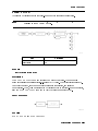
Surveillance Receiver
ABCDE
HP Part No. 71910-90002
Printed in USA
December 1996
Edition A.0.0
Notice
The information contained in this document is subject to change without notice.
Hewlett-Packard makes no warranty of any kind with regard to this material, including,
but not limited to, the implied warranties of merchantability and tness for a particular
purpose. Hewlett-Packard shall not be liable for errors contained herein or for incidental or
consequential damages in connection with the furnishing, performance, or use of this material.
Restricted Rights Legend.
Use, duplication, or disclosure by the U.S. Government is subject to restrictions as set forth
in subparagraph (c) (1) (ii) of the Rights in Technical Data and Computer Software clause
at DFARS 252.227-7013 for DOD agencies, and subparagraphs (c) (1) and (c) (2) of the
Commercial Computer Software Restricted Rights clause at FAR 52.227-19 for other agencies.
This instrument has been designed and tested in accordance with IEC Publication 348, Safety
Requirements for Electronic Measuring Apparatus , and has been supplied in a safe condition.
The instruction documentation contains information and warnings which must be followed by
the user to ensure safe operation and to maintain the instrument in a safe condition.
c Copyright Hewlett-Packard Company 1994{1996
All Rights Reserved. Reproduction, adaptation, or translation without prior written
permission is prohibited, except as allowed under the copyright laws.
1400 Fountaingrove Parkway, Santa Rosa, CA 95403-1799, USA
Safety
WARNING
No operator serviceable parts inside. Refer servicing to qualified personnel. To
prevent electrical shock, do not remove covers.
WARNING
For continued protection against fire hazard, replace line fuse only with same
type and ratings (type 6.3A/250V). The use of other fuses or materials is
prohibited.
CAUTION
WARNING
Always use the three-prong ac power cord supplied with this instrument.
Failure to ensure adequate earth grounding by not using this cord may cause
instrument damage.
This is a Safety Class 1 Product (provided with a protective earthing ground
incorporated in the power cord.) The mains plug shall only be inserted in a
socket outlet provided with a protective earth contact. Any interruption of the
protective conductor inside or outside of the instrument is likely to make the
instrument dangerous. Intentional interruption is prohibited.
CAUTION
This instrument is designed for use in Installation Category II and Pollution
Degree 2 per IEC 1010 and 664 respectively.
When installing the instrument in a cabinet, the
convection into and out of the instrument must not be restricted. The ambient
temperature (outside the cabinet) must be less than the maximum operating
temperature of the instrument by 4 C for every 100 watts dissipated in the
cabinet. If the total power dissipated in the cabinet is greater than 800 watts,
then forced convection must be used.
CAUTION
Ventilation Requirements:
WARNING
If this instrument is not used as specified, the protection provided by the
equipment could be impaired. This instrument must be used in a normal
condition (in which all means for protection are intact) only.
iii
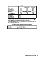
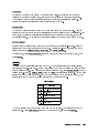
Surveillance with the HP 71910A
The HP 71910A Wide-Bandwidth Surveillance Receiver provides both signal search and signal
collection capability from 100 Hz to 26.5 GHz. It is optimized for surveillance and signal
monitoring applications. The HP 71910A can be operated in either of the following two
instrument modes:
Spectrum analyzer operation for signal searches
Maximum resolution BW
3 MHz
Wide-bandwidth receiver operation for signal collection
IF BW
10 to 100 MHz
:::::::::::::::::::::::::::::::::::::::::::::::::
:::::::::::::::::::::::::::::::::::::::::::::::::::::::::::
Note
When you use the wide-bandwidth surveillance receiver, remember that in
spectrum analyzer mode the maximum resolution bandwidth is 3 MHz; it is
not a 100 MHz bandwidth spectrum analyzer.
The receiver's IF and video outputs can be examined by oscilloscopes, demodulators,
digitizers, FFT baseband analyzers, and other instruments.
HP 71910A Wide-Bandwidth Surveillance Receiver
iv
HP 71910A Option 011
When rst turned on, the wide-bandwidth surveillance receiver operates as a spectrum
analyzer. This allows you to view signals across a large frequency range. Once you've located
a signal, switch to the xed-tuned receiver mode to downconvert the signal.
The downconverted signal is available at the rear panel for processing and analyzing by
external devices. The Option 011 version of the instrument is primarily used as a collection
receiver; it has very limited spectrum analyzer capability due to linear detection and 3 MHz
maximum peak detection bandwidth. (Option 013 adds an HP 70902A to provide a more
complete spectrum analyzer.)
IF outputs are available at the rear panel
In receiver mode, the downconverted signal is available at the instrument's rear panel. The
standard rear-panel output is centered at 321.4 MHz. Option 001 and 002 instruments provide
additional 70 MHz and 140 MHz IF signals respectively. Refer to Chapter 3 for examples of
processing these signals.
v
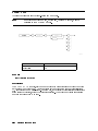
Demodulated outputs are available at the front panel
The front-panel VIDEO connector provides AM and pulse demodulation. Option 004 provides
additional I/Q outputs and Option 005 provides an additional FM output. Refer to Chapter 3
for examples of processing these signals.
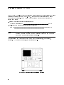
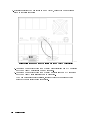
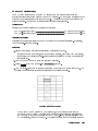
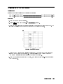
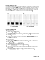
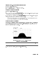
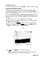
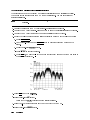
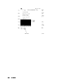
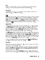
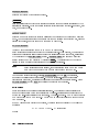
Option 004 instruments (together with an external oscilloscope in XY mode), provide a
convenient method of identifying modulation formats such as 8 PSK, 16 QAM, and 64 QAM.
With typical receivers, the constellations \spin" due to the oset in frequency between the
receiver and the signal. This makes format identication very dicult. But, because of the
wide-bandwidth surveillance receiver's 1 Hz frequency tuning, this spinning movement can be
slowed to the point where it is almost stopped.
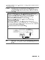
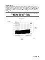
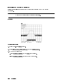
256 QAM Constellation Displayed on Oscilloscope
vi
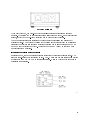
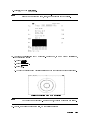
Switch between operating mode with the press of a button
Press 4USER5 and then RX_MODE for use as a wide-bandwidth surveillance receiver.
Press 4MENU5 for use as a spectrum analyzer.
This is the default state when the instrument is rst turned on.
Press 4DISPLAY5 to access functions for controlling the display.
You will seldom need to use this key. For information on functions accessed with this key,
refer to the HP 70004A DISPLAY Operating Manual .
Press 4INSTR5 to switch between multiple instrument windows.
Multiple instrument windows must rst be congured as shown in Chapter 3.
NNNNNNNNNNNNNNNNNNNNNNN
vii
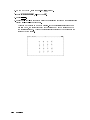
Changing measurement parameters is easy
Use the front-panel knob, step keys, or numeric keypad to enter new measurements settings.
For example, press the 4CENTER5 key to change the displayed center frequency. After changing
the setting, pressing the 4HOLD5 key disables the keypad, knob, and step keys until another
function is selected.
Use the 45 (backspace) key to speed your navigation through softkey menus. When pressed,
the previous softkey menu is displayed. Also, use this key to backspace over numbers entered
using the data-entry keypad.
Conventions
The following key conventions are used in this guide:
4Front-panel key5
Text shown like this represents a key physically located on the receiver.
Text shown like this represents a softkey. (The softkeys are located next to
Softkey
the softkey labels, and the softkey labels are the annotation on the right or
left side of the spectrum analyzer display.)
Screen Text Text printed in this typeface indicates text displayed on the instrument's
screen.
NNNNNNNNNNNNNNNNNNNNNNN
viii
L
Instrument Markings
The instruction documentation symbol. The product is marked with this symbol when
it is necessary for the user to refer to the instructions in the documentation.
\CE" The CE mark is a registered trademark of the European Community. (If accompanied
by a year, it is when the design was proven.)
\ISM1-A" This is a symbol of an Industrial Scientic and Medical Group 1 Class A product.
\CSA" The CSA mark is a registered trademark of the Canadian Standards Association.
denotes a hazard. It calls attention to a procedure that, if not
correctly performed or adhered to, could result in damage to or destruction of
the instrument. Do not proceed beyond a caution note until the indicated
conditions are fully understood and met.
CAUTION
Caution
WARNING
Warning
denotes a hazard. It calls attention to a procedure which, if not
correctly performed or adhered to, could result in injury or loss of life. Do
not proceed beyond a
warning
note until the indicated conditions are fully
understood and met.
ix
Assistance
Product maintenance agreements and other customer assistance agreements are available for
Hewlett-Packard products. For any assistance, contact your nearest Hewlett-Packard Sales
and Service Oce.
Regulatory Information
Regulatory information is located in Chapter 5, \Specications and Characteristics."
Certification
Hewlett-Packard Company certies that this product met its published specications at the
time of shipment from the factory. Hewlett-Packard further certies that its calibration
measurements are traceable to the United States National Institute of Standards and
Technology, to the extent allowed by the Institute's calibration facility, and to the calibration
facilities of other International Standards Organization members.
x
Warranty
This Hewlett-Packard instrument product is warranted against defects in material and
workmanship for a period of one year from date of shipment. During the warranty period,
Hewlett-Packard Company will, at its option, either repair or replace products which prove to
be defective.
For warranty service or repair, this product must be returned to a service facility designated
by Hewlett-Packard. Buyer shall prepay shipping charges to Hewlett-Packard and
Hewlett-Packard shall pay shipping charges to return the product to Buyer. However, Buyer
shall pay all shipping charges, duties, and taxes for products returned to Hewlett-Packard
from another country.
Hewlett-Packard warrants that its software and rmware designated by Hewlett-Packard for
use with an instrument will execute its programming instructions when properly installed on
that instrument. Hewlett-Packard does not warrant that the operation of the instrument, or
software, or rmware will be uninterrupted or error-free.
Limitation of Warranty
The foregoing warranty shall not apply to defects resulting from improper or inadequate
maintenance by Buyer, Buyer-supplied software or interfacing, unauthorized modication or
misuse, operation outside of the environmental specications for the product, or improper
site preparation or maintenance.
NO OTHER WARRANTY IS EXPRESSED OR IMPLIED. HEWLETT-PACKARD
SPECIFICALLY DISCLAIMS THE IMPLIED WARRANTIES OF MERCHANTABILITY
AND FITNESS FOR A PARTICULAR PURPOSE.
Exclusive Remedies
THE REMEDIES PROVIDED HEREIN ARE BUYER'S SOLE AND EXCLUSIVE
REMEDIES. HEWLETT-PACKARD SHALL NOT BE LIABLE FOR ANY DIRECT,
INDIRECT, SPECIAL, INCIDENTAL, OR CONSEQUENTIAL DAMAGES, WHETHER
BASED ON CONTRACT, TORT, OR ANY OTHER LEGAL THEORY.
xi
xii
Contents
1. Getting Started
To install the receiver . . . . . . . . . .
To install an Option 011 receiver . . . . .
To install an HP 70911A into an HP 71209A
To install an HP 70620B preamp . . . . .
Maintaining the Receiver . . . . . . . .
To clean the HP 70004A's screen . . . .
To change the mainframe's fuse . . . . .
To change the custom keypad . . . . .
To locate a module's serial number . . .
Reinstalling the Receiver Personality . . .
To install from the memory card . . . .
To install from a 3.5-inch diskette drive .
To install in an Option 011 instrument .
Returning the Receiver for Service . . . .
To return a receiver for service . . . . .
.
.
.
.
.
.
.
.
.
.
.
.
.
.
.
.
.
.
.
.
.
.
.
.
.
.
.
.
.
.
.
.
.
.
.
.
.
.
.
.
.
.
.
.
.
.
.
.
.
.
.
.
.
.
.
.
.
.
.
.
.
.
.
.
.
.
.
.
.
.
.
.
.
.
.
.
.
.
.
.
.
.
.
.
.
.
.
.
.
.
.
.
.
.
.
.
.
.
.
.
.
.
.
.
.
.
.
.
.
.
.
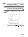
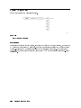
.
.
.
.
.
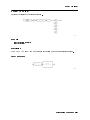
.
.
.
.
.
.
.
.
.
.
.
.
.
.
.
.
.
.
.
.
.
.
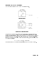
.
.
.
.
.
.
.
.
.
.
.
.
.
.
.
.
.
.
.
.
.
.
.
.
.
.
.
.
.
.
.
.
.
.
.
.
.
.
.
.
.
.
.
.
.
.
.
.
.
.
.
.
.
.
.
.
.
.
.
.
.
.
.
.
.
.
.
.
.
.
.
.
.
.
.
.
.
.
.
.
.
.
.
.
.
.
.
1-2
1-12
1-14
1-25
1-28
1-28
1-28
1-29
1-30
1-31
1-32
1-33
1-34
1-35
1-35
Calibrating the HP 71910A . . . . . . . . . . .
To perform a calibration . . . . . . . . . . . .
To perform a calibration with HP 70620B preamp .
Searching for Signals (spectrum analyzer mode) . . .
Locating Signals . . . . . . . . . . . . . . .
To change the frequency range . . . . . . . .
To return to full span . . . . . . . . . . . .
To change the reference level and amplitude scale
To change the amplitude units . . . . . . . .
Using Markers . . . . . . . . . . . . . . . .
To view a signal using markers . . . . . . . .
Resolving Signals . . . . . . . . . . . . . . .
To resolve closely spaced signals . . . . . . .
Reducing Displayed Noise . . . . . . . . . . .
To reduce the displayed noise . . . . . . . . .
Controlling the Sweep . . . . . . . . . . . . .
To change the sweep time . . . . . . . . . .
To set continuous or single sweeps . . . . . . .
Changing Center-Frequency Step Size . . . . . .
To change the center frequency step size . . . .
Collecting Signals (receiver mode) . . . . . . . . .
Changing to Receiver Mode . . . . . . . . . .
.
.
.
.
.
.
.
.
.
.
.
.
.
.
.
.
.
.
.
.
.
.
.
.
.
.
.
.
.
.
.
.
.
.
.
.
.
.
.
.
.
.
.
.
.
.
.
.
.
.
.
.
.
.
.
.
.
.
.
.
.
.
.
.
.
.
.
.
.
.
.
.
.
.
.
.
.
.
.
.
.
.
.
.
.
.
.
.
.
.
.
.
.
.
.
.
.
.
.
.
.
.
.
.
.
.
.
.
.
.
.
.
.
.
.
.
.
.
.
.
.
.
.
.
.
.
.
.
.
.
.
.
.
.
.
.
.
.
.
.
.
.
.
.
.
.
.
.
.
.
.
.
.
.
.
.
.
.
.
.
.
.
.
.
.
.
.
.
.
.
.
.
.
.
.
.
.
.
.
.
.
.
.
.
.
.
.
.
.
.
.
.
.
.
.
.
.
.
.
.
.
.
.
.
.
.
.
.
.
.
.
.
.
.
.
.
.
.
.
.
.
.
.
.
.
.
.
.
.
.
.
.
.
.
.
.
.
.
.
.
.
.
3-3
3-3
3-3
3-4
3-5
3-6
3-7
3-7
3-7
3-8
3-8
3-10
3-10
3-11
3-11
3-12
3-12
3-12
3-13
3-13
3-14
3-16
2. System Verication of Operation
3. Operating
Contents-1
To switch to receiver mode . . . . . . . . . . . . . .
To select a new signal . . . . . . . . . . . . . . . .
To return to spectrum analyzer mode . . . . . . . . .
Selecting IF Outputs and Channel Filters . . . . . . . .
To select an IF output . . . . . . . . . . . . . . . .
To adjust the IF and video bandwidth . . . . . . . . .
To change the IF-to-video bandwidth ratio . . . . . . .
To increase the 321.4 MHz bandwidth (preselector bypass)
To adjust the IF gain and RF attenuation . . . . . . .
To select an Option 007 channel lter . . . . . . . . .
Demodulating Signals . . . . . . . . . . . . . . . . .
To demodulate the signal . . . . . . . . . . . . . .
To adjust IQ gain, oset, and quadrature . . . . . . .
Viewing the Signal's Average Amplitude Level . . . . . .
To view the average amplitude . . . . . . . . . . . .
Measurement Examples . . . . . . . . . . . . . . . .
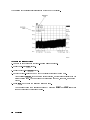
To search for and collect a pulsed RF signal . . . . . .
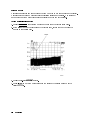
To characterize a wide-bandwidth FM signal . . . . . .
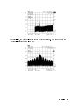
To characterize a wide-bandwidth digital transmission . .
Manually Collecting Signals . . . . . . . . . . . . . . .
Using Manual Mode . . . . . . . . . . . . . . . . . .
To manually enter collection receiver mode . . . . . . .
To search for and collect a pulsed RF signal . . . . . . .
Using a Preamplier . . . . . . . . . . . . . . . . . . .
To use the HP 70620B preamp . . . . . . . . . . . . .
To turn o the preamp in receiver mode . . . . . . . . .
Extending the Frequency Range with External Mixers . . . .
Controlling System Conguration . . . . . . . . . . . . .
To save a receiver state . . . . . . . . . . . . . . . .
To recall or delete a receiver state . . . . . . . . . . . .
To view two instrument windows . . . . . . . . . . . .
To blank the display . . . . . . . . . . . . . . . . .
To write a title on the screen . . . . . . . . . . . . . .
Block Diagrams . . . . . . . . . . . . . . . . . . . . .
If You Have a Problem . . . . . . . . . . . . . . . . .
If UNCOR is displayed . . . . . . . . . . . . . . . .
If UNCAL and Usable RBW limited is displayed . . . . .
If UNCAL and Usable VBW limited is displayed . . . . .
If Possible compression is displayed . . . . . . . . . . .
If the PREAMP On O softkey doesn't work . . . . . . .
If there is a frequency shift in an HP 70911A output . . .
Contents-2
.
.
.
.
.
.
.
.
.
.
.
.
.
.
.
.
.
.
.
.
.
.
.
.
.
.
.
.
.
.
.
.
.
.
.
.
.
.
.
.
.
.
.
.
.
.
.
.
.
.
.
.
.
.
.
.
.
.
.
.
.
.
.
.
.
.
.
.
.
.
.
.
.
.
.
.
.
.
.
.
.
.
.
.
.
.
.
.
.
.
.
.
.
.
.
.
.
.
.
.
.
.
.
.
.
.
.
.
.
.
.
.
.
.
.
.
.
.
.
.
.
.
.
.
.
.
.
.
.
.
.
.
.
.
.
.
.
.
.
.
.
.
.
.
.
.
.
.
.
.
.
.
.
.
.
.
.
.
.
.
.
.
.
.
.
.
.
.
.
.
.
.
.
.
.
.
.
.
.
.
.
.
.
.
.
.
.
.
.
.
.
.
.
.
.
.
.
.
.
.
.
.
.
.
.
.
.
.
.
.
.
.
.
.
.
.
.
.
.
.
.
.
.
.
.
.
.
.
.
.
.
.
.
.
.
.
.
.
.
.
.
.
.
.
.
.
.
.
.
.
.
.
.
.
.
.
.
.
.
.
.
.
.
.
.
.
.
.
.
.
.
.
.
.
.
.
.
.
.
.
.
.
.
.
.
.
.
3-16
3-18
3-18
3-19
3-22
3-22
3-22
3-23
3-23
3-23
3-25
3-27
3-27
3-28
3-28
3-29
3-29
3-34
3-38
3-41
3-43
3-45
3-46
3-49
3-50
3-50
3-51
3-52
3-53
3-55
3-56
3-56
3-57
3-59
3-62
3-63
3-64
3-65
3-66
3-67
3-68
4. Programming
Getting Started . . . . . . . . . . . . . . . . . . . . . .
To connect the equipment . . . . . . . . . . . . . . . .
HP BASIC Programming Example . . . . . . . . . . . . .
Communicating with the Receiver . . . . . . . . . . . . . .
Initial Commands . . . . . . . . . . . . . . . . . . . .
Executing Remote Commands . . . . . . . . . . . . . .
Local and Remote Control . . . . . . . . . . . . . . .
Transfering Data to the Computer . . . . . . . . . . . . .
Monitoring System Operation . . . . . . . . . . . . . . .
Interrupt Process . . . . . . . . . . . . . . . . . . . .
Receiver Status Byte . . . . . . . . . . . . . . . . .
The Service-Request Mask . . . . . . . . . . . . . . .
Monitoring System Operation without Using Service Requests
5. Specications and Characteristics
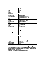
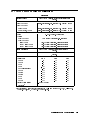
Denitions of Terms . . . . . . . . . . . .
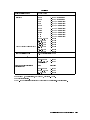
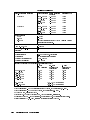
HP 71910A Collection Receiver Specications
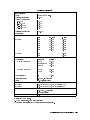
HP 71910A Search Receiver Specications . .
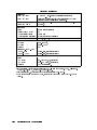
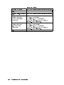
General Specications . . . . . . . . . . .
Physical Dimensions of Mainframes . . . . .
Regulatory Information . . . . . . . . . .
Notice for Germany: Noise Declaration . .
.
.
.
.
.
.
.
.
.
.
.
.
.
.
.
.
.
.
.
.
.
.
.
.
.
.
.
.
.
.
.
.
.
.
.
.
.
.
.
.
.
.
.
.
.
.
.
.
.
.
.
.
.
.
.
.
.
.
.
.
.
.
.
.
.
.
.
.
.
.
.
.
.
.
.
.
.
.
4-2
4-3
4-4
4-5
4-5
4-5
4-6
4-7
4-8
4-8
4-8
4-9
4-10
.
.
.
.
.
.
.
.
.
.
.
.
.
.
.
.
.
.
.
.
.
.
.
.
.
.
.
.
.
.
.
.
.
.
.
.
.
.
.
.
.
.
.
.
.
.
.
.
.
.
.
.
.
.
.
.
.
.
.
.
.
.
.
.
.
.
.
.
.
.
.
.
.
.
.
.
.
.
.
.
.
.
.
.
.
.
.
.
.
.
.
.
.
.
.
.
.
.
5-2
5-3
5-9
5-15
5-16
5-17
5-18
.
.
.
.
.
.
.
.
.
.
.
.
.
.
.
.
.
.
.
.
.
.
.
.
.
.
.
.
.
.
.
.
.
.
.
.
.
.
.
.
.
.
.
.
.
.
.
.
.
.
.
.
.
.
.
.
.
.
.
.
.
.
.
.
.
.
.
.
.
.
.
.
.
.
.
.
.
.
.
.
.
.
.
.
.
.
.
.
.
.
.
.
.
.
.
.
.
.
.
.
.
.
.
.
.
.
.
.
.
.
.
.
.
.
.
.
.
.
.
.
.
.
.
.
.
.
.
.
.
.
.
.
.
.
.
.
.
.
.
.
.
.
.
.
.
.
.
.
.
.
.
.
.
.
.
.
.
.
.
.
.
.
.
.
.
.
.
.
.
.
.
.
.
.
.
.
.
.
.
.
.
.
.
.
.
.
.
.
.
.
.
.
.
.
.
.
.
.
.
.
.
.
.
.
.
.
.
.
.
.
.
.
.
.
.
.
.
.
.
.
.
.
.
.
.
.
.
.
.
.
.
.
.
.
.
.
.
.
.
.
.
.
.
.
.
.
.
.
.
.
.
.
.
.
.
.
.
.
.
.
.
.
.
.
.
.
.
.
.
.
.
.
.
.
.
.
.
.
.
.
.
.
.
.
.
.
.
.
.
.
.
.
.
.
.
.
.
.
.
.
.
.
.
.
.
.
.
.
7-2
7-2
7-2
7-2
7-2
7-2
7-2
7-2
7-2
7-3
7-3
7-3
7-3
7-3
7-3
7-3
7-3
7-4
7-4
7-4
7-4
7-4
6. Menu Maps
7. Dictionary Reference
Alphabetical Listing . .
1.25 MHz . . . . .
5 MHz . . . . . . .
10 MHz . . . . . .
20 MHz . . . . . .
36 MHz . . . . . .
70 MHz . . . . . .
70 MHz OUT . . .
140 MHz OUT . . .
300 MHz IN . . . .
300 MHz OUT . . .
321.4 MHz IN . . .
321.4 MHz OPT IN .
321.4 MHz OPT OUT
321.4 MHz OUT . .
70911 OPTIONS . .
45 . . . . . . . .
485 495 . . . . . . .
415 . . . . . . . .
A UNITS AutoMan .
AM . . . . . . . .
BYPASS . . . . . .
NNNNNNNNNNNNNNNNNNNNNNNNNN
NNNNNNNNNNNNNNNNN
NNNNNNNNNNNNNNNNNNNN
NNNNNNNNNNNNNNNNNNNN
NNNNNNNNNNNNNNNNNNNN
NNNNNNNNNNNNNNNNNNNN
NNNNNNNNNNNNNNNNNNNNNNNNNNNNNNNNNNNNNNNNN
NNNNNNNNNNNNNNNNNNNNNNNNNNNNNNNNNNNNNNNNNNNNNNN
NNNNNNNN
NNNNNNNNNNNNNNNNNNNN
.
.
.
.
.
.
.
.
.
.
.
.
.
.
.
.
.
.
.
.
.
.
.
.
.
.
.
.
.
.
.
.
.
.
.
.
.
.
.
.
.
.
.
.
.
.
.
.
.
.
.
.
.
.
.
.
.
.
.
.
.
.
.
.
.
.
.
.
.
.
.
.
.
.
.
.
.
.
.
.
.
.
.
.
.
.
.
.
.
.
.
.
.
.
.
.
.
.
.
.
.
.
.
.
.
.
.
.
.
.
.
.
.
.
.
.
.
.
.
.
.
.
.
.
.
.
.
.
.
.
.
.
.
.
.
.
.
.
.
.
.
.
.
.
.
.
.
.
.
.
.
.
.
.
.
.
.
.
.
.
.
.
.
.
.
.
.
.
.
.
.
.
.
.
.
.
.
.
.
.
.
.
.
.
.
.
.
.
.
.
.
.
.
.
.
.
.
.
.
.
.
.
.
.
.
.
.
.
.
.
.
.
.
.
.
.
.
.
.
.
Contents-3
. . . . . . . . .
4CENTER5 . . . . . . .
CENTER . . . . . . .
CF STEP AutoMan . .
channel filters . .
dBm . . . . . . . . .
dBmV . . . . . . . .
dBuV . . . . . . . .
DEL RX STATE . . . .
Demod . . . . . . . .
DISPLAY On Off . . .
FM . . . . . . . . .
FM NB . . . . . . . .
FM WB . . . . . . . .
Freq . . . . . . . .
FULL SPAN . . . . .
Gain . . . . . . . .
Help On Off . . . .
4HOLD5 . . . . . . . .
HP-MSIB CARD . . . .
HPIB DISK . . . . .
I . . . . . . . . . .
I GAIN . . . . . . .
I OFFSET . . . . . .
IF BW . . . . . . . .
IF GAIN AutoMan . .
4INSTR5 . . . . . . . .
4INSTR PRESET5
. . . .
INTRNL MEMORY . . .
IQ . . . . . . . . .
LAST STATE . . . . .
4MENU5 . . . . . . . .
Misc . . . . . . . .
NARROW SPAN . . . .
NB VID IN . . . . .
4NEXT PEAK5
. . . . .
4NORMAL5 . . . . . . .
4PEAK SEARCH5 . . . . .
4PLOT5 . . . . . . . .
PREAMP On Off . . .
PRESEL On Off . . .
4PRINT5 . . . . . . . .
PULSE . . . . . . . .
NNNNNNNN
BW
NNNNNNNNNNNNNNNNNNNN
NNNNNNNNNNNNNNNNNNNNNNNNNNNNNNNNNNNNNNNNNNNNNNN
NNNNNNNNNNNNNNNNNNNNNNNNNNNNNNNNNNNNNNNNNNNNNNN
NNNNNNNNNNN
NNNNNNNNNNNNNN
NNNNNNNNNNNNNN
NNNNNNNNNNNNNNNNNNNNNNNNNNNNNNNNNNNNNN
NNNNNNNNNNNNNNNNN
NNNNNNNNNNNNNNNNNNNNNNNNNNNNNNNNNNNNNNNNNNNN
NNNNNNNNNNNNNNNNN
NNNNNNNNNNNNNNNNN
NNNNNNNNNNNNNN
NNNNNNNNNNNNNNNNNNNNNNNNNNNNN
NNNNNNNNNNNNNN
NNNNNNNNNNNNNNNNNNNNNNNNNNNNNNNNNNN
NNNNNNNNNNNNNNNNNNNNNNNNNNNNNNNNNNNNNN
NNNNNNNNNNNNNNNNNNNNNNNNNNNNN
NNNNNNNNNNNNNNNNNNNN
NNNNNNNNNNNNNNNNNNNNNNNNNN
NNNNNNNNNNNNNNNNN
NNNNNNNNNNNNNNNNNNNNNNNNNNNNNNNNNNNNNNNNNNNNNNN
NNNNNNNNNNNNNNNNNNNNNNNNNNNNNNNNNNNNNNNNN
NNNNNNNN
NNNNNNNNNNNNNNNNNNNNNNNNNNNNNNNN
NNNNNNNNNNNNNN
NNNNNNNNNNNNNNNNNNNNNNNNNNNNNNNNNNN
NNNNNNNNNNNNNNNNNNNNNNNNNNNNNNNNNNNNNNNNN
NNNNNNNNNNNNNNNNNNNNNNNNNNNNNNNNNNNNNNNNN
NNNNNNNNNNNNNNNNN
Contents-4
.
.
.
.
.
.
.
.
.
.
.
.
.
.
.
.
.
.
.
.
.
.
.
.
.
.
.
.
.
.
.
.
.
.
.
.
.
.
.
.
.
.
.
.
.
.
.
.
.
.
.
.
.
.
.
.
.
.
.
.
.
.
.
.
.
.
.
.
.
.
.
.
.
.
.
.
.
.
.
.
.
.
.
.
.
.
.
.
.
.
.
.
.
.
.
.
.
.
.
.
.
.
.
.
.
.
.
.
.
.
.
.
.
.
.
.
.
.
.
.
.
.
.
.
.
.
.
.
.
.
.
.
.
.
.
.
.
.
.
.
.
.
.
.
.
.
.
.
.
.
.
.
.
.
.
.
.
.
.
.
.
.
.
.
.
.
.
.
.
.
.
.
.
.
.
.
.
.
.
.
.
.
.
.
.
.
.
.
.
.
.
.
.
.
.
.
.
.
.
.
.
.
.
.
.
.
.
.
.
.
.
.
.
.
.
.
.
.
.
.
.
.
.
.
.
.
.
.
.
.
.
.
.
.
.
.
.
.
.
.
.
.
.
.
.
.
.
.
.
.
.
.
.
.
.
.
.
.
.
.
.
.
.
.
.
.
.
.
.
.
.
.
.
.
.
.
.
.
.
.
.
.
.
.
.
.
.
.
.
.
.
.
.
.
.
.
.
.
.
.
.
.
.
.
.
.
.
.
.
.
.
.
.
.
.
.
.
.
.
.
.
.
.
.
.
.
.
.
.
.
.
.
.
.
.
.
.
.
.
.
.
.
.
.
.
.
.
.
.
.
.
.
.
.
.
.
.
.
.
.
.
.
.
.
.
.
.
.
.
.
.
.
.
.
.
.
.
.
.
.
.
.
.
.
.
.
.
.
.
.
.
.
.
.
.
.
.
.
.
.
.
.
.
.
.
.
.
.
.
.
.
.
.
.
.
.
.
.
.
.
.
.
.
.
.
.
.
.
.
.
.
.
.
.
.
.
.
.
.
.
.
.
.
.
.
.
.
.
.
.
.
.
.
.
.
.
.
.
.
.
.
.
.
.
.
.
.
.
.
.
.
.
.
.
.
.
.
.
.
.
.
.
.
.
.
.
.
.
.
.
.
.
.
.
.
.
.
.
.
.
.
.
.
.
.
.
.
.
.
.
.
.
.
.
.
.
.
.
.
.
.
.
.
.
.
.
.
.
.
.
.
.
.
.
.
.
.
.
.
.
.
.
.
.
.
.
.
.
.
.
.
.
.
.
.
.
.
.
.
.
.
.
.
.
.
.
.
.
.
.
.
.
.
.
.
.
.
.
.
.
.
.
.
.
.
.
.
.
.
.
.
.
.
.
.
.
.
.
.
.
.
.
.
.
.
.
.
.
.
.
.
.
.
.
.
.
.
.
.
.
.
.
.
.
.
.
.
.
.
.
.
.
.
.
.
.
.
.
.
.
.
.
.
.
.
.
.
.
.
.
.
.
.
.
.
.
.
.
.
.
.
.
.
.
.
.
.
.
.
.
.
.
.
.
.
.
.
.
.
.
.
.
.
.
.
.
.
.
.
.
.
.
.
.
.
.
.
.
.
.
.
.
.
.
.
.
.
.
.
.
.
.
.
.
.
.
.
.
.
.
.
.
.
.
.
.
.
.
.
.
.
.
.
.
.
.
.
.
.
.
.
.
.
.
.
.
.
.
.
.
.
.
.
.
.
.
.
.
.
.
.
.
.
.
.
.
.
.
.
.
.
.
.
.
.
.
.
.
.
.
.
.
.
.
.
.
.
.
.
.
.
.
.
.
.
.
.
.
.
.
.
.
.
.
.
.
.
.
.
.
.
.
.
.
.
.
.
.
.
.
.
.
.
.
.
.
.
.
.
.
.
.
.
.
.
.
.
.
.
.
.
.
.
.
.
.
.
.
.
.
.
.
.
.
.
.
.
.
.
.
.
.
.
.
.
.
.
.
.
.
.
.
.
.
.
.
.
.
.
.
.
.
.
.
.
.
.
.
.
.
.
.
.
.
.
.
.
.
.
.
.
.
.
.
.
.
.
.
.
.
.
.
.
.
.
.
.
.
.
.
.
.
.
.
.
.
.
.
.
.
.
.
.
.
.
.
.
.
.
.
.
.
.
.
.
.
.
.
.
.
.
.
.
.
.
.
.
.
.
.
.
.
.
.
.
.
.
.
.
.
.
.
.
.
.
.
.
.
.
.
.
.
.
.
.
.
.
.
.
7-4
7-4
7-5
7-5
7-5
7-5
7-5
7-5
7-5
7-5
7-6
7-6
7-6
7-6
7-6
7-6
7-7
7-7
7-7
7-7
7-7
7-8
7-8
7-8
7-8
7-9
7-9
7-9
7-10
7-10
7-10
7-10
7-10
7-10
7-10
7-11
7-11
7-11
7-11
7-11
7-11
7-12
7-12
Q . . . . . .
Q GAIN . . .
Q OFFSET . .
QUADRATURE .
.
.
.
.
RCL RX STATE .
4RECALL5 . . . .
.
.
.
.
.
.
.
.
.
.
.
.
.
.
.
.
.
.
.
.
.
.
.
.
.
.
.
.
.
.
.
.
.
.
.
.
.
.
.
.
.
.
.
.
.
.
.
.
.
.
.
.
.
.
.
.
.
.
.
.
.
.
.
.
.
.
.
.
.
.
.
.
.
.
.
.
.
.
.
.
.
.
.
.
.
.
.
.
.
.
.
.
.
.
.
.
.
.
.
.
.
.
.
.
.
.
.
.
.
.
.
.
.
.
.
.
.
.
.
.
.
.
.
.
.
.
.
.
.
.
.
.
.
.
.
.
.
.
.
.
.
.
.
.
.
.
.
.
.
.
.
.
.
.
.
.
.
.
.
.
.
.
.
.
.
.
.
.
.
.
.
.
.
.
.
.
.
.
.
.
.
.
.
.
.
.
.
.
.
.
.
.
.
.
.
.
.
.
.
.
.
.
.
.
.
.
.
.
.
.
.
.
.
.
.
.
.
.
.
.
.
.
.
.
.
.
.
.
.
.
.
.
.
.
.
.
.
.
.
.
.
.
.
.
.
.
.
.
.
.
.
.
.
.
.
.
.
.
.
.
.
.
.
.
.
.
.
.
.
.
.
.
.
.
.
.
.
.
.
.
.
.
.
.
.
.
.
.
.
.
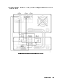
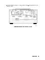
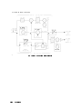
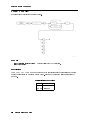
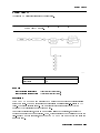
.
.
.
.
.
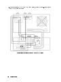
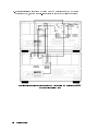
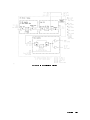
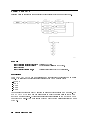
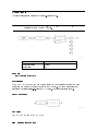
.
.
.
.
.
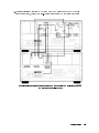
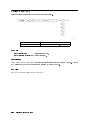
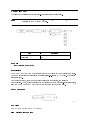
.
.
.
.
.
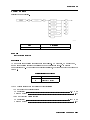
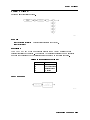
.
.
.
.
.
.
.
.
.
.
.
.
.
.
.
.
.
.
.
.
.
.
.
.
.
.
.
.
.
.
.
.
.
.
.
.
.
.
.
.
.
.
.
.
.
.
.
.
.
.
.
.
.
.
.
.
.
.
.
.
.
.
.
.
.
.
.
.
.
.
.
.
.
.
.
.
.
.
.
.
.
.
.
.
.
.
.
.
.
.
.
.
.
.
.
.
.
.
.
.
.
.
.
.
.
.
.
.
.
.
.
.
.
.
.
.
.
.
.
.
.
.
.
.
.
.
.
.
.
.
.
.
.
.
.
.
.
.
.
.
.
.
.
.
.
.
.
.
.
.
.
.
.
.
.
.
.
.
.
.
.
.
.
.
.
.
.
.
.
.
.
.
.
.
.
.
.
.
.
.
.
.
.
.
.
.
.
.
.
.
.
.
.
.
.
.
.
.
.
.
.
.
.
.
.
.
.
.
.
.
.
.
.
.
.
.
.
.
.
.
.
.
.
.
.
.
.
.
.
.
.
.
.
.
.
.
.
.
.
.
.
.
.
.
.
.
.
.
.
.
.
.
.
.
.
.
.
.
.
.
.
.
.
.
.
.
.
.
.
.
.
.
.
.
.
.
.
.
.
.
.
.
.
.
.
.
.
.
.
.
.
.
.
.
.
.
.
.
.
.
.
.
.
.
.
.
.
.
.
.
.
.
.
.
.
.
.
.
.
.
.
.
.
.
.
.
.
.
.
.
.
.
.
.
.
.
.
.
.
.
.
.
.
.
.
.
.
.
.
.
.
.
.
.
.
.
.
.
.
.
.
.
.
.
.
.
.
.
.
.
.
.
.
.
.
.
.
.
.
.
.
.
.
.
.
.
.
.
.
.
.
.
.
.
.
.
.
.
.
.
.
.
.
.
.
.
.
.
7-12
7-12
7-13
7-13
7-13
7-13
7-14
7-14
7-14
7-14
7-14
7-15
7-15
7-15
7-16
7-16
7-16
7-16
7-16
7-16
7-17
7-17
7-17
7-17
7-17
7-17
7-17
7-18
7-18
7-18
7-18
Syntax Conventions . . . .
Softkeys Versus Commands
RXRMT CHANFILT . . .
RXRMT CHANPATH . . .
RXRMT DELETERX . . .
RXRMT DEMOD . . . .
RXRMT FMOFF . . . . .
RXRMT IFGAIN . . . . .
RXRMT IGAIN . . . . .
RXRMT INIT . . . . . .
RXRMT IOFFSET . . . .
RXRMT OPTIONS? . . .
RXRMT QGAIN . . . . .
.
.
.
.
.
.
.
.
.
.
.
.
.
.
.
.
.
.
.
.
.
.
.
.
.
.
.
.
.
.
.
.
.
.
.
.
.
.
.
.
.
.
.
.
.
.
.
.
.
.
.
.
.
.
.
.
.
.
.
.
.
.
.
.
.
.
.
.
.
.
.
.
.
.
.
.
.
.
.
.
.
.
.
.
.
.
.
.
.
.
.
.
.
.
.
.
.
.
.
.
.
.
.
.
.
.
.
.
.
.
.
.
.
.
.
.
.
.
.
.
.
.
.
.
.
.
.
.
.
.
.
.
.
.
.
.
.
.
.
.
.
.
.
.
.
.
.
.
.
.
.
.
.
.
.
.
.
.
.
.
.
.
.
.
.
.
.
.
.
.
.
.
.
.
.
.
.
.
.
.
.
.
.
.
.
.
.
.
.
.
.
.
.
.
.
.
.
.
.
.
.
.
.
.
.
.
.
.
.
.
.
.
.
.
.
.
.
.
.
.
.
.
.
.
.
.
.
.
.
.
.
.
.
.
.
.
.
.
.
.
.
.
.
.
.
.
.
.
.
.
.
.
.
.
.
.
.
.
.
.
.
.
.
.
.
.
.
.
.
.
.
.
.
.
.
.
.
.
.
.
.
.
.
.
.
.
8-2
8-4
8-6
8-8
8-10
8-11
8-13
8-15
8-16
8-17
8-18
8-19
8-20
NNNNNNNNNNNNNNNNNNNN
NNNNNNNNNNNNNNNNNNNNNNNNNN
NNNNNNNNNNNNNNNNNNNNNNNNNNNNNNNN
NNNNNNNNNNNNNNNNNNNNNNNNNNNNNNNNNNNNNN
NNNNNNNNNNNNNNNNNNNNNNNNNNNNNNNNNNNNNNNNNNNNNNN
RECEIVR VERSION
.
.
.
.
.
.
REF LEVEL5 . . . .
4
NNNNNNNNNNNNNNNNNNNNNNNNNNNNNNNNNNNNNNNNN
Return to S/A
RF ATTN AutoMan
NNNNNNNNNNNNNNNNNNNNNNNNNNNNNNNNNNNNNNNNNNNNNNN
.
RF/IF Gain: . . .
save & recall .
SAVE RX STATE .
SIG LVL On Off .
4SIGNAL TRACK5 . .
4SPAN5 . . . . . .
SPAN . . . . . .
4START FREQ5 . . .
. . .
4STOP FREQ5
temp compens . .
TITLE . . . . . .
units menu . . .
4USER5 . . . . . .
VBW/IFB RATIO .
VID BW AutoMan .
VID OUT TO L.O.
VIDEO . . . . .
VOLT . . . . . .
WATT . . . . . .
WB VID IN . . .
WB VID OUT . .
NNNNNNNNNNNNNNNNNNNNNNNNNNNNNNNNNNNNNNNNN
NNNNNNNNNNNNNNNNNNNNNNNNNNNNNNNNNNNNNNNNN
NNNNNNNNNNNNNNNNNNNNNNNNNNNNNNNNNNNNNNNNNNNN
NNNNNNNNNNNNNN
NNNNNNNNNNNNNNNNNNNNNNNNNNNNNNNNNNNNNN
NNNNNNNNNNNNNNNNN
NNNNNNNNNNNNNNNNNNNNNNNNNNNNNNNN
NNNNNNNNNNNNNNNNNNNNNNNNNNNNNNNNNNNNNNNNN
NNNNNNNNNNNNNNNNNNNNNNNNNNNNNNNNNNNNNNNNNNNN
NNNNNNNNNNNNNN
NNNNNNNNNNNNNN
.
.
.
.
.
.
.
.
.
.
.
.
.
.
.
.
.
.
.
.
.
.
.
.
.
.
.
.
.
.
.
8. Programming Commands
.
.
.
.
.
.
.
.
.
.
.
.
.
.
.
.
.
.
.
.
.
.
.
.
.
.
.
.
.
.
.
Contents-5
RXRMT QOFFSET .
RXRMT QUAD . . .
RXRMT RECALLRX .
RXRMT SAVERX . .
RXRMT TEMPCOMP
RXRMT VERSION? .
.
.
.
.
.
.
.
.
.
.
.
.
.
.
.
.
.
.
.
.
.
.
.
.
.
.
.
.
.
.
.
.
.
.
.
.
.
.
.
.
.
.
.
.
.
.
.
.
.
.
.
.
.
.
.
.
.
.
.
.
.
.
.
.
.
.
.
.
.
.
.
.
.
.
.
.
.
.
.
.
.
.
.
.
.
.
.
.
.
.
.
.
.
.
.
.
.
.
.
.
.
.
.
.
.
.
.
.
.
.
.
.
.
.
.
.
.
.
.
.
.
.
.
.
.
.
.
.
.
.
.
.
.
.
.
.
.
.
.
.
.
.
.
.
8-21
8-22
8-24
8-25
8-26
8-27
Error Message Descriptions . . . . . . . . . . . . . . . . . . . . . .
Troubleshooting Features . . . . . . . . . . . . . . . . . . . . . . .
9-2
9-6
9. Error Messages
10. Tables and Charts
11. Conguring and Addressing
Modular Measurement System Terms . . . . . . . .
Functional Terms . . . . . . . . . . . . . . . .
Element . . . . . . . . . . . . . . . . . . .
Master . . . . . . . . . . . . . . . . . . .
Sub-master . . . . . . . . . . . . . . . . . .
Slave . . . . . . . . . . . . . . . . . . . .
Independent element . . . . . . . . . . . . .
Instrument . . . . . . . . . . . . . . . . . .
Structural Terms . . . . . . . . . . . . . . . .
Mainframe . . . . . . . . . . . . . . . . . .
Module . . . . . . . . . . . . . . . . . . .
Stand-Alone Instrument . . . . . . . . . . . .
Address Map Protocol . . . . . . . . . . . . . . .
Address Matrix . . . . . . . . . . . . . . . . .
Display-Response Area . . . . . . . . . . . . .
HP-IB Access . . . . . . . . . . . . . . . . .
Addressing Elements . . . . . . . . . . . . . . .
Master Elements . . . . . . . . . . . . . . . .
Sub-Master Elements . . . . . . . . . . . . . .
Slave Elements . . . . . . . . . . . . . . . . .
Slave Area Boundaries . . . . . . . . . . . . . .
Independent Elements . . . . . . . . . . . . . .
Addressing Order Requirements . . . . . . . . . .
Default Addressing for Congured HP 70000 Systems
Addressing Criteria . . . . . . . . . . . . . . .
HP 70900B local oscillator source . . . . . . . .
HP 70902A IF section . . . . . . . . . . . . .
HP 70700A digitizer . . . . . . . . . . . . . .
HP 70911A ultra-wide bandwidth IF section . . .
HP 70903A IF section . . . . . . . . . . . . .
HP 70907B . . . . . . . . . . . . . . . . . .
RF section . . . . . . . . . . . . . . . . . .
HP 70600A preselector/HP 70601A preselector . .
HP 70300A RF tracking generator . . . . . . .
HP 70301A microwave tracking generator . . . .
HP 70310A precision frequency reference . . . . .
HP 70621A or HP 70620B preampliers . . . . .
Contents-6
.
.
.
.
.
.
.
.
.
.
.
.
.
.
.
.
.
.
.
.
.
.
.
.
.
.
.
.
.
.
.
.
.
.
.
.
.
.
.
.
.
.
.
.
.
.
.
.
.
.
.
.
.
.
.
.
.
.
.
.
.
.
.
.
.
.
.
.
.
.
.
.
.
.
.
.
.
.
.
.
.
.
.
.
.
.
.
.
.
.
.
.
.
.
.
.
.
.
.
.
.
.
.
.
.
.
.
.
.
.
.
.
.
.
.
.
.
.
.
.
.
.
.
.
.
.
.
.
.
.
.
.
.
.
.
.
.
.
.
.
.
.
.
.
.
.
.
.
.
.
.
.
.
.
.
.
.
.
.
.
.
.
.
.
.
.
.
.
.
.
.
.
.
.
.
.
.
.
.
.
.
.
.
.
.
.
.
.
.
.
.
.
.
.
.
.
.
.
.
.
.
.
.
.
.
.
.
.
.
.
.
.
.
.
.
.
.
.
.
.
.
.
.
.
.
.
.
.
.
.
.
.
.
.
.
.
.
.
.
.
.
.
.
.
.
.
.
.
.
.
.
.
.
.
.
.
.
.
.
.
.
.
.
.
.
.
.
.
.
.
.
.
.
.
.
.
.
.
.
.
.
.
.
.
.
.
.
.
.
.
.
.
.
.
.
.
.
.
.
.
.
.
.
.
.
.
.
.
.
.
.
.
.
.
.
.
.
.
.
.
.
.
.
.
.
.
.
.
.
.
.
.
.
.
.
.
.
.
.
.
.
.
.
.
.
.
.
.
.
.
.
.
.
.
.
.
.
.
.
.
.
.
.
.
.
.
.
.
.
.
11-2
11-2
11-2
11-2
11-2
11-2
11-2
11-2
11-2
11-2
11-2
11-3
11-4
11-4
11-5
11-5
11-6
11-6
11-6
11-7
11-7
11-8
11-9
11-9
11-9
11-9
11-9
11-10
11-10
11-10
11-10
11-10
11-10
11-10
11-10
11-10
11-10
Row Addressing Priority . .
Address Switches . . . . . .
Master Address Switches . .
HP-IB ON/OFF . . . .
SW1/MEM . . . . . .
MAS/SLA . . . . . . .
NRML/TEST . . . . .
COLUMNs 1|5 . . . .
ROWs 1|3 . . . . . .
Slave Address Switches . .
Rows 1|3 . . . . . . .
Columns 1|5 . . . . .
Display Address Switches .
HP-IB ON/OFF . . . .
A1|A5 . . . . . . . .
TALK ONLY . . . . . .
SYSTEM CONTROLLER
TEST MODE . . . . .
.
.
.
.
.
.
.
.
.
.
.
.
.
.
.
.
.
.
.
.
.
.
.
.
.
.
.
.
.
.
.
.
.
.
.
.
.
.
.
.
.
.
.
.
.
.
.
.
.
.
.
.
.
.
.
.
.
.
.
.
.
.
.
.
.
.
.
.
.
.
.
.
.
.
.
.
.
.
.
.
.
.
.
.
.
.
.
.
.
.
.
.
.
.
.
.
.
.
.
.
.
.
.
.
.
.
.
.
.
.
.
.
.
.
.
.
.
.
.
.
.
.
.
.
.
.
.
.
.
.
.
.
.
.
.
.
.
.
.
.
.
.
.
.
.
.
.
.
.
.
.
.
.
.
.
.
.
.
.
.
.
.
.
.
.
.
.
.
.
.
.
.
.
.
.
.
.
.
.
.
.
.
.
.
.
.
.
.
.
.
.
.
.
.
.
.
.
.
.
.
.
.
.
.
.
.
.
.
.
.
.
.
.
.
.
.
.
.
.
.
.
.
.
.
.
.
.
.
.
.
.
.
.
.
.
.
.
.
.
.
.
.
.
.
.
.
.
.
.
.
.
.
.
.
.
.
.
.
.
.
.
.
.
.
.
.
.
.
.
.
.
.
.
.
.
.
.
.
.
.
.
.
.
.
.
.
.
.
.
.
.
.
.
.
.
.
.
.
.
.
.
.
.
.
.
.
.
.
.
.
.
.
.
.
.
.
.
.
.
.
.
.
.
.
.
.
.
.
.
.
.
.
.
.
.
.
.
.
.
.
.
.
.
.
.
.
.
.
.
.
.
.
.
.
.
.
.
.
.
.
.
.
.
.
.
.
.
.
.
.
.
.
.
.
.
.
.
.
11-11
11-12
11-12
11-13
11-13
11-13
11-13
11-13
11-13
11-14
11-14
11-14
11-14
11-14
11-14
11-15
11-15
11-15
Index
Contents-7
Tables
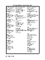
10-1. Hewlett-Packard Sales and Service Oces . . . . . . . . . . . . . . .
Contents-8
10-4
1
Getting Started
This chapter shows you how to install and maintain the HP 71910A and its various options.
In addition, there is a procedure for installing an HP 70911A wide bandwidth IF module into
an existing HP 71209A Option 001 spectrum analyzer.
No special tools are required except for the procedure \To install an HP 70911A in your
HP 71209A." This procedure requires an 8 mm ball driver. Be careful to observe all notes,
cautions, and warnings in the procedures.
Contents
To install the receiver
To install an Option 011 receiver
To install an HP 70911A into an HP 71209A
To install an HP 70620B preamp
1-2
1-12
1-14
1-25
::::::::::::::::::::::::::::::::::::::::::::::::::::::::::::::::::
::::::::::::::::::::::::::::::::::::::::::::::::::::::
::::::::::::::::::::::::::::::::::::::::::
::::::::::::::::::::::::::::::::::::::::::::::::::::::
Maintaining the Receiver
To clean the HP 70004A's screen
To change the mainframe's fuse
To change the custom keypad
To locate a module's serial number
:::::::::::::::::::::::::::::::::::::::::::::::::::::::::::::
:::::::::::::::::::::::::::::::::::::::::::::::::::
::::::::::::::::::::::::::::::::::::::::::::::::::::
::::::::::::::::::::::::::::::::::::::::::::::::::::::
:::::::::::::::::::::::::::::::::::::::::::::::::
Reinstalling the Receiver Personality
To install from the memory card
To install from a 3.5-inch diskette drive
To install in an Option 011 instrument
::::::::::::::::::::::::::::::::::::::::::::::::::
:::::::::::::::::::::::::::::::::::::::::::::::::::
::::::::::::::::::::::::::::::::::::::::::::
:::::::::::::::::::::::::::::::::::::::::::::
1-28
1-28
1-28
1-29
1-30
1-31
1-32
1-33
1-34
Returning the Receiver for Service
1-35
To return a receiver for service
1-35
The following installation procedure applies to both the HP 71910A wide
bandwidth surveillance receiver and the HP 71910P wide bandwidth
surveillance receiver. In a \P" system, the HP 70207A PC Display for MMS
replaces the HP 70004A color display.
There are no specication changes between the \P" and \A" systems, only
module placement and rear-panel cabling are dierent.
Refer to the HP 70207A User's Guide for complete installation instructions of
the HP 70207A PC Display for MMS, the MSIB interface card, and the MSIB
Y-cable that is used with a \P" system.
::::::::::::::::::::::::::::::::::::::::::::::::::::
:::::::::::::::::::::::::::::::::::::::::::::::::::::
Note
Getting Started
1-1
To install the receiver
1. Inspect the shipping container or cushioning material for damage.
If there is damage or a defect, save the packing materials, le a claim with the carrier,
then contact the nearest Hewlett-Packard sales and service oce for immediate repair
or replacement.
2. Make sure the instrument's line-voltage selectors are set to the same voltage as the power
source.
CAUTION
Note
WARNING
Before turning the instrument on, be sure the LINE VOLTAGE SELECTOR is set
to the correct voltage for the power source. Failure to do this may cause
damage (a blown fuse) to the system when the power cable is plugged in.
Option 400 instruments for 400 Hz operation come with an external in-line
isolation transformer for use with the HP 70001A mainframe. The isolation
transformer protects the user from shock hazard. The in-line isolation
transformer must be removed for 60 Hz power-source operation. Failure to
remove the in-line transformer may result in a blown fuse. The HP 70004A
display/mainframe does not require an option to operate on 400 Hz.
Do not operate a 400 Hz option receiver on a 400 Hz power line without the
attached in-line isolation transformer for the HP 70001A mainframe. Failure to
follow this precaution can result in personal injury.
1-2
Getting Started
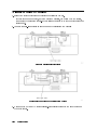
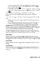
3. If you're installing a standard HP 71910A, connect the rear-panel cables as shown in the
following gure:
Rear-Panel Connections for the Standard HP 71910A
Getting Started
1-3
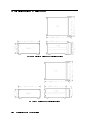
4. If you're installing an HP 71910A that has an option, connect the rear-panel cables as
shown in the following gure:
Rear-Panel Connections for the HP 71910A with Options
1-4
Getting Started
5. If you're installing a standard HP 71910P, connect the rear-panel cables as shown in the
following gure:
Rear-Panel Connections for the Standard HP 71910P
Getting Started
1-5
6. If you're installing a standard HP 71910P with two mainframes and an HP 70902A
IF section added, connect the rear-panel cables as shown in the following gure:
Rear-Panel Connections for the Standard HP 71910P with Two Mainframes and an
HP 70902A IF Section Added
1-6
Getting Started
7. If you're installing a standard HP 71910P with two mainframes and an HP 70620B
preamplier added, connect the rear-panel cables as shown in the following gure:
Rear-Panel Connections for the Standard HP 71910P with Two Mainframes and an
HP 70620B Preamplifier Added
Getting Started
1-7
8. If you're connecting the MSIB cables on an HP 71910A, connect the MSIB cables as
shown in the following gure:
MSIB Cabling from the HP 70001A Mainframe to the HP 70004A Color Display
a. Connect an MSIB cable between the HP 70004A color display's MSIB OUT connector
and the HP 70001A mainframe's MSIB IN connector.
b. Connect an MSIB cable between the HP 70001A mainframe's MSIB OUT connector
and the HP 70004A color display's MSIB IN connector.
The MSIB cables are connected serially, coupling the input of one element to the
output of the next until the loop is completed.
1-8
Getting Started
9. If you're connecting the MSIB Y-Cable on an HP 71910P, connect the cables as shown in
the following gure:
CAUTION
Care should be taken when connecting the MSIB Y-cable to the
MSIB interface card. Damage can occur if the MSIB Y-cable connection is
not properly aligned. Ensure power is not applied while making or removing
connections.
a. Remove the protective cap from the MSIB Y-cable and inspect the pins for damage or
misalignment. Do not install MSIB Y-cable if pins are bent or damaged. If necessary, obtain
service from Hewlett-Packard. Refer to \Returning the Receiver for Service".
b. Align the MSIB Y-cable to the MSIB interface card's MSIB connector (1).
Do not force the connectors together! (See the above caution.)
c. Tighten the captive-screws on the MSIB Y-cable to the MSIB interface card.
Do not over tighten the screws!
d. Connect the two free-ends of the MSIB Y-cable (that are not connected to the
MSIB interface card) to the HP 70001A mainframe's IN and OUT MSIB connectors (2).
The MSIB cables are connected serially, coupling the input of one HP 70001A mainframe to
the output of the next until a loop is completed.
e. Connect the ac line cord to your computer and display.
Note
Refer to the HP 70207A User's Guide for complete installation instructions of
the HP 70207A PC Display for MMS, the MSIB interface card, and the MSIB
Y-cable.
Getting Started
1-9
10. Connect the power cables to both instrument mainframes rst, then plug the cables into
the power outlet.
11. Set the HP 70001A mainframe's 4 5 LINE switch to ON, and listen to verify that the
ventilation fan starts up.
12. If an HP 70004A color display is being used in your system (such as the HP 71910A), set
the 4 5 LINE switch to ON, and listen to verify that the ventilation fan starts up.
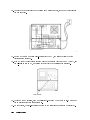
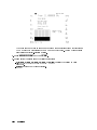
13. Except on the IF sections, each module's front-panel ACT LED should be lit. Only one of
the IF sections will have its ACT light on.
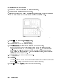
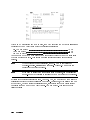
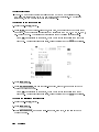
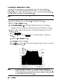
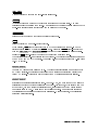
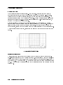
14. On the display, the left-side softkeys shown in the following gure should be displayed.
1-10
Getting Started
If the receiver menu softkeys do not appear after power-up, the display window
probably is not assigned to the receiver. To assign it, perform the following steps:
a. Press the 4DISPLAY5 key on the display's front panel to access the main menu for the
display.
b. Press the NEXT INSTR softkey until the receiver is selected for independent
operation.
c. Press the 4MENU5 key to display the seven softkeys for stand-alone operation of the
receiver.
NNNNNNNNNNNNNNNNNNNNNNNNNNNNNNNN
Getting Started
1-11
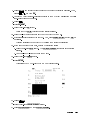
To install an Option 011 receiver
1. Inspect the shipping container or cushioning material for damage.
If there is damage or a defect, save the packing materials, le a claim with the carrier,
then contact the nearest Hewlett-Packard sales and service oce for immediate repair or
replacement.
2. Connect the rear-panel cables as shown in one of the following two gures:
Standard Rear-Panel Connections
Rear-Panel Connections for Receiver with Options
3. Make sure the HP 70001A mainframe's line-voltage selector is set to the same voltage as
the power source.
1-12
Getting Started
CAUTION
Note
WARNING
Before turning the instrument on, be sure the LINE VOLTAGE SELECTOR is set
to the correct voltage for the power source. Failure to do this may cause
damage (a blown fuse) to the system when the power cable is plugged in.
Option 400 instruments for 400 Hz operation come with an external in-line
isolation transformer for use with the HP 70001A mainframe. The isolation
transformer protects the user from shock hazard. The in-line isolation
transformer must be removed for 60 Hz power-source operation. Failure to
remove the in-line transformer may result in a blown fuse.
Do not operate a 400 Hz option receiver on a 400 Hz power line without the
attached in-line isolation transformer for the HP 70001A mainframe. Failure to
follow this precaution can result in personal injury.
4. Connect the power cable to the HP 70001A mainframe rst, then plug the cable into the
power outlet.
5. Set the HP 70001A mainframe's 4 5 LINE switch to ON, and listen to verify that the
ventilation fan starts up.
6. Check to see that each module's front-panel ACT LED lights.
Getting Started
1-13
To install an HP 70911A into an HP 71209A
This procedure shows you how to install an HP 70911A module into an already existing HP
71209A Option 001 spectrum analyzer. Option 001 spectrum analyzers have an HP 70910A
wide-bandwidth RF module instead of the standard HP 70909A RF module.
Older HP 71209A Option 001 spectrum analyzers may need to be modied before you can
install the HP 70911A ultra-wide bandwidth section which includes options. This is explained
in the following paragraphs.
HP 70001A mainframe upgrade
If the HP 70001A mainframe has a serial number of 3327A05741 or earlier, an upgrade kit
must be installed that increases the power and airow capability. The serial number is located
by opening the HP 70001A's front-panel door to expose the hex-lock screws that are used for
installing modules. The serial number label is located behind this door on the inside of the
right frame section.
WARNING
In order to provide proper cooling for the HP 70911A module which includes
options, the HP 70001A mainframe must have a serial number higher than
3327A05741. If the HP 70001A serial number is 3327A05741 or below, contact
your local Hewlett-Packard sales and service office for information on installing
an upgrade kit. HP 70911A modules that do not include option cards will not
require the retrofit kit.
HP 70900B LO upgrade
The HP 70900B local oscillator module must have rmware 940120 or later and include the 1
MByte memory option. To view the rmware date code, do the following steps:
1. Press 4MENU5.
2. Press the left-side Misc softkey.
3. Press MORE 1 of 3 and then service .
4. Press ROM VERSION .
When upgrading an existing HP 71209A Option 001, order the HP 70911A Option 099 or
098 to obtain the LO rmware and memory upgrade. An HP 71910A system already includes
these items. To determine which option (098 or 099) is required, do the following steps:
1. Press 4MENU5.
2. Press the left-side State softkey.
3. Press MORE 1 of 4 , MORE 2 of 4 , and then show states .
4. Press EXTEND STATE .
5. Find the CPU: heading that is displayed on the screen.
6. If the entry reads 68000, the HP 70911A Option 098 is required. If the entry reads 68020,
the HP 70911A Option 099 is required.
NNNNNNNNNNNNNN
NNNNNNNNNNNNNNNNNNNNNNNNNNNNNNNNNNN
NNNNNNNNNNNNNNNNNNNNNNN
NNNNNNNNNNNNNNNNNNNNNNNNNNNNNNNNNNN
NNNNNNNNNNNNNNNNN
NNNNNNNNNNNNNNNNNNNNNNNNNNNNNNNNNNN
NNNNNNNNNNNNNNNNNNNNNNNNNNNNNNNNNNNNNN
1-14
Getting Started
NNNNNNNNNNNNNNNNNNNNNNNNNNNNNNNNNNN
NNNNNNNNNNNNNNNNNNNNNNNNNNNNNNNNNNN
HP 70910A RF section upgrade
The HP 71910A includes an HP 70910A RF section with rmware enhancements for
moderately faster tuning than older HP 70910A RF sections. HP 70910A's with serial number
3409A00170 and later include this newer rmware. The newer rmware is not necessary for
proper operation. Contact an HP service center for upgrade information.
Tools needed
Install the module requires one of the following drivers:
8 mm hex-ball driver (long)
8 mm hex-ball driver (short)
::::::::::::::::::::::::::::::::::::
:::::::::::::::::::::::::::::::::::
HP part number 8710-1307
HP part number 8710-1651
Antistatic precautions
Electrical components are easily damaged by small amounts of static electricity. If possible,
work at a static-free work station.
Procedure
1. Inspect the shipping container or cushioning material for damage.
If there is damage or a defect, save the packing materials, le a claim with the carrier,
then contact the nearest Hewlett-Packard sales and service oce for immediate repair
or replacement.
2. Turn on your HP 71209A Option 001 spectrum analyzer.
3. Press 4DISPLAY5 and then the left-side Address Map softkey.
4. Turn the front-panel knob to scroll the address map so that the modules are shown. The
address map should look like the one displayed in the following gure.
NNNNNNNNNNNNNNNNNNNNNNNNNNNNNNNNNNN
Address Map of HP 71209A
The HP 70911A has a default MMS address of 3,18 which places it between the
HP 70903A and HP 70902A modules in the above gure. If this space is unavailable,
you may need to change the address of the HP 70911A. For a general discussion of
MMS addressing, refer to Chapter 11. The following gure shows the address switches
Getting Started
1-15
on the HP 70911A module. The switches are set to the default MMS address of ROW 3
and COLUMN 18.
5. Turn o the ac line power to the HP 71209A, and remove the two line-power cords from
the mainframes.
1-16
Getting Started
6. Open the HP 70001A mainframe's front-panel door to expose the hex-lock screw.
7. Using an 8 mm hex-ball driver, turn the hex-lock bolts counterclockwise to unlock and
remove the two blank panels shown in the following gure.
8. Install the new HP 70911A module next to the HP 70310A.
Getting Started
1-17
1-18
Getting Started
9. If you're installing a standard HP 70911A module, connect the rear-panel cables as shown
in the following gure.
Rear-Panel Connections for Standard Configuration
Note
If you have an HP 71910P conguration, refer to the section, \To install the
receiver", which is located at the beginning of this chapter.
Getting Started
1-19
10. If you're installing an Option 001/002 HP 70911A module, connect the rear-panel cables
as shown in the following gure.
Rear-Panel Connections for Option 001/002
1-20
Getting Started
11. Connect the power cables to both instrument mainframes rst, then plug the cables into
the power outlet.
12. Set the HP 70001A mainframe's 4 5 LINE switch to ON, and listen to verify that the
ventilation fan starts up.
13. If an HP 70004A color display is being used in your system (such as the HP 71910A), set
the 4 5 LINE switch to ON, and listen to verify that the ventilation fan starts up.
14. Check to see that each module's front-panel ACT LED lights. When two IF sections are in
the system, only the one that is selected will have its ACT light on.
15. If an ERR LED remains on, check the address map as described in the following steps.
a. Press 4DISPLAY5.
b. Press the left-side Address Map softkey.
c. Turn the front-panel knob to scroll the address map so that it looks similar the one
shown in the following gure. Make sure that the order of the modules is such that the
ROW addresses (highest to lowest) are as shown in the following gure. For example,
the HP 70911A must be \above" the HP 70902A and \below" the HP 70903A. The
location of the empty ROW addresses is not important.
NNNNNNNNNNNNNNNNNNNNNNNNNNNNNNNNNNN
Getting Started
1-21
Example of a Correct Address Map
16. Press the 4DISPLAY5 key on the display's front panel to access the main menu for the
display.
17. Press the NEXT INSTR softkey until the left-side softkeys shown in the following gure are
displayed.
NNNNNNNNNNNNNNNNNNNNNNNNNNNNNNNN
18. Press the 4MENU5 key to display the seven softkeys for stand-alone operation of the
receiver.
19. Locate the memory card containing the receiver personality.
20. Locate the arrow printed on one end of the card.
1-22
Getting Started
21. Insert the card into the HP 70004A display's front-panel card slot. Match the card's
arrow with the arrow printed above the card slot.
22. Press 4MENU5 and then the left-side Misc softkey.
23. Press MORE 1 of 3 and then catalog & MSI .
24. Press HP-MSIB CARD to display all les contained on the memory card.
NNNNNNNNNNNNNN
NNNNNNNNNNNNNNNNNNNNNNNNNNNNNNNNNNN
NNNNNNNNNNNNNNNNNNNNNNNNNNNNNNNNNNNNNNNNN
NNNNNNNNNNNNNNNNNNNNNNNNNNNNNNNNNNNNNN
If 2053 Storage device error is displayed, either the card is missing, the card's
write-protect switch is in the SAFE position, or the card's HP-MSIB address is listed
incorrectly. The HP-MSIB address for the card is the same address as the display's
HP-IB address and is normally set to 4. If the address is not correct, enter the correct
address using the numeric keypad.
25. Press LOAD FILE , and enter 1 for the le number.
26. Press ENTER .
NNNNNNNNNNNNNNNNNNNNNNNNNNNNN
NNNNNNNNNNNNNNNNN
The front-panel LED next to the card slot lights indicating that the les are being
copied into the 4USER5 menu. This process takes approximately 60 seconds.
27. Press 4USER5 and then RX_MODE to start the receiver personality.
28. The left-side softkeys, shown in the following gure, should be visible.
NNNNNNNNNNNNNNNNNNNNNNN
Getting Started
1-23
1-24
Getting Started
To install an HP 70620B preamp
Tools needed
Install the module requires one of the following drivers:
8 mm hex-ball driver (long)
8 mm hex-ball driver (short)
::::::::::::::::::::::::::::::::::::
:::::::::::::::::::::::::::::::::::
HP part number 8710-1307
HP part number 8710-1651
Procedure
1. Turn on your HP 71910A receiver.
2. Press 4DISPLAY5 and then the left-side Address Map softkey.
3. Turn the front-panel knob to scroll the address map so that the modules are shown. The
address map should look like the one displayed in the following gure.
NNNNNNNNNNNNNNNNNNNNNNNNNNNNNNNNNNN
Address Map of HP 71910A
4. Locate the HP 70620B preamplier's address switch. Make sure that the switches are
set to a value of ROW 6 and COLUMN 19. This will position the HP 70620B below any
HP 70310A precision frequency reference that might be present.
5. Turn o the ac line power to the HP 71209A, and remove the two line-power cords from
the mainframes.
Getting Started
1-25
6. Open the HP 70001A mainframe's front-panel door to expose the hex-lock screw.
7. Using an 8 mm hex-ball driver, turn the hex-lock bolt to remove the blank panel that is
located to the right of the HP 70910A RF section.
8. Install the HP 70620B in the empty slot.
9. Connect a cable between the HP 70620B's front-panel RF INPUT connector and the
HP 70910A's front-pane RF OUTPUT connector.
10. Set the HP 70001A mainframe's 4 5 LINE switch to ON.
11. Set the HP 70004A mainframe's 4 5 LINE switch to ON.
12. If an ERR LED remains on, check the address map as described in the following steps.
a. Press 4DISPLAY5.
b. Press the left-side Address Map softkey.
c. Turn the front-panel knob to scroll the address map so that it looks similar the one
shown in the following gure. Your receiver may not have an HP 70310A precision
frequency reference. Make sure that the order of the modules is such that the ROW
addresses (highest to lowest) are as shown in the following gure. The location of the
empty ROW addresses is not important.
NNNNNNNNNNNNNNNNNNNNNNNNNNNNNNNNNNN
Example of a Correct Address Map
13. Press the 4DISPLAY5 key on the display's front panel to access the main menu for the
display.
14. Press the NEXT INSTR softkey until the left-side softkeys shown in the following gure are
displayed.
NNNNNNNNNNNNNNNNNNNNNNNNNNNNNNNN
1-26
Getting Started
15. Calibrate the two available RF INPUTs using the calibration procedure listed in
\Calibrating the HP 71910A" in Chapter 3. The procedure is entitled \To perform a
partial calibration with HP 70620B preamp."
Getting Started
1-27
Maintaining the Receiver
The following procedures will help you to maintain the appearance and operation of the HP
71910A Wide-Bandwidth Surveillance Receiver.
To clean the HP 70004A's screen
Use a thin-lm cleaner and abrasion-free cleaning tissue or soft cloth to clean the display.
An example of a proper thin-lm cleaner is the Hewlett-Packard Display Cleaner (HP
part number 8500-2163).
CAUTION
Do not use hands or paper towels to clean the display's screen. These abrasive
materials may scratch the screen coating.
To change the mainframe's fuse
This procedure applies to either the HP 70001A mainframe or HP 70004A display/mainframe.
1. Turn o the ac line power to the receiver, and remove the line-power cables from the power
outlet.
2. Remove the line-power cable from the connector located on the mainframe's rear panel.
The fuse holder is located is the line-power cable connector.
3. Use a small at-blade screwdriver to prey out the fuse holder as shown in the following
gure.
4. Check the fuse for damage. As shown in the gure, a spare fuse is included in the assembly.
The metric 6.3A fuse (HP part number 2110-0703) can be used with both 120V and
230V power sources.
1-28
Getting Started
To change the custom keypad
The custom keypad snaps into the HP 70004A mainframe's front panel. This keypad gives
you quick access to common instrument functions.
In the unlikely event that you need to change the keypad, perform the following step:
Push the tip of a small at-bladed screwdriver straight into the removal hole, and the
keypad will pop out.
CAUTION
Be sure to insert the screwdriver straight into the removal hole; do not pry the
custom keypad out.
Getting Started
1-29
To locate a module's serial number
A two-part serial number appears on the mylar label attached to the front frame of the
modules. The rst four digits and the letter are the serial number prex; the last ve
digits, the sux. Identical receivers have the same prex, which changes only for signicant
modication. The sux is dierent for each receiver.
1. Open the front-panel door to expose the hex-lock screw.
2. The serial number label is attached to the module's front frame.
1-30
Getting Started
Reinstalling the Receiver Personality
In the unlikely event that the receiver personality becomes corrupted or is deleted from
memory, this section shows how to reinstall it into the HP 71910A. To determine if the
receiver personality is installed, press 4USER5 and then RX_MODE . The receiver softkey menus
should appear on the display.
NNNNNNNNNNNNNNNNNNNNNNN
Receiver Softkey Menu
Backup copies of the receiver personality are provided in the following forms:
Memory card.
3.5-inch diskette (HP-LIF format).
For standard HP 71910A systems, copy the receiver personality from the memory card. If
your HP 71910A is an Option 011 (without HP 70004A display), you must copy the programs
from an external HP-IB disk drive. The diskette containing the receiver personality uses the
LIF format.
Getting Started
1-31
To install from the memory card
1. Locate the memory card containing the receiver personality.
2. Locate the arrow printed on one end of the card.
3. Insert the card into the HP 70004A display's front-panel card slot. Match the card's arrow
with the arrow printed above the card slot as shown in the following gure.
4. Press 4MENU5 and then the left-side Misc softkey.
5. Press MORE 1 of 3 and then catalog & MSI .
6. Press HP-MSIB CARD to display all les contained on the memory card.
If 2053 Storage device error is displayed, either the card is missing, the card's
write-protect switch is in the SAFE position, or the card's HP-MSIB address is listed
incorrectly. The HP-MSIB address for the card is the same address as the display's
HP-IB address and is normally set to 4. If the address is not correct, enter the correct
address using the numeric keypad.
7. Press LOAD FILE , and enter 1 for the le number.
8. Press ENTER .
The front-panel LED next to the card slot lights indicating that the les are being copied
into the 4USER5 menu. This process takes approximately 60 seconds.
9. Press 4USER5 and then RX_MODE to start the receiver personality.
NNNNNNNNNNNNNN
NNNNNNNNNNNNNNNNNNNNNNNNNNNNNNNNNNN
NNNNNNNNNNNNNNNNNNNNNNNNNNNNNNNNNNNNNNNNN
NNNNNNNNNNNNNNNNNNNNNNNNNNNNNNNNNNNNNN
NNNNNNNNNNNNNNNNNNNNNNNNNNNNN
NNNNNNNNNNNNNNNNN
NNNNNNNNNNNNNNNNNNNNNNN
1-32
Getting Started
To install from a 3.5-inch diskette drive
This procedure reinstalls the personality into a standard HP 71910A system. If you have an
Option 011 system, perform the next procedure in this section. The disk drive must be a 3.5
inch, CS80-compatible drive, such as an HP 9122.
1. Connect a 3.5-inch diskette drive to the HP 70004A display or HP 70001A mainframe.
Use an HP-IB cable.
2. Insert the diskette containing the receiver personality into the diskette drive.
3. Press 4MENU5.
4. Press the left-side Misc softkey.
5. Press MORE 1 of 3 and then catalog & MSI .
NNNNNNNNNNNNNN
NNNNNNNNNNNNNNNNNNNNNNNNNNNNNNNNNNN
NNNNNNNNNNNNNNNNNNNNNNNNNNNNNNNNNNNNNNNNN
6. Press HP DISK , and use the numeric keypad to enter the diskette drive's address.
The default address is 0, unit 0, and volume 0. New addresses are entered in the form
A.UV , where:
A is a digit from 1 to 30, representing the drive's HP-IB address.
U is a digit from 0 to 9, representing the unit number. The unit number is typically
0 or 1 and refers to an individual disk drive slot.
V is a digit from 0 to 9, representing the volume number. Volume numbers are used
for hard disk drives. So, for reading diskettes, the volume number should be 0.
For example, entering 3.00 indicates an address of 3, a unit number of 0 and a volume
number of 0. This accesses a diskette in the left drive of an external diskette drive at
HP-IB address 3.
7. Press the ENTER softkey.
If 2053 Storage device error is displayed, either a diskette is not in the drive, or the
drive's code is incorrectly entered.
8. Press LOAD FILE , and enter a 1 for the le number.
9. Press ENTER to reinstall the le.
NNNNNNNNNNNNNNNNNNNNNNN
NNNNNNNNNNNNNNNNN
NNNNNNNNNNNNNNNNNNNNNNNNNNNNN
NNNNNNNNNNNNNNNNN
The front-panel LED next to the card slot lights indicating that the les are being
copied into the 4USER5 menu. This process takes approximately 60 seconds.
10. Press 4USER5 to and then RX_MODE to start the receiver personality.
NNNNNNNNNNNNNNNNNNNNNNN
Getting Started
1-33
To install in an Option 011 instrument
This procedure reinstalls the personality into an Option 011 instrument. It requires the use
of a computer and an HP-IB disk drive. The disk drive must be a 3.5 inch, CS80-compatible
drive, such as an HP 9122.
In order to use this procedure, you must rst write a program that sends a string to the
HP 70900B instructing it to load the personality. The string includes a \wait" command that
delays the loading of the personality for 20 seconds. This pause gives you time to move the
HP-IB cable from the computer to the disk drive. If you need more time, increase this wait
value in the command WAIT 20.
1. Write a program that sends the following string to the HP 70900B module. (The HP-IB
address of the HP 70900B is equal to the HP-MSIB column address of the HP 70900B.)
MSI HPIB,0.1; WAIT 20; LOAD /RX/;
2.
3.
4.
5.
6.
In the string, the digit 0 represents the disk drive's HP-IB address. The digit 1
represents the individual disk drive slot. This number is typically 0 or 1.
Use an HP-IB cable to connect the computer to the HP 70001A mainframe. Do not
connect the disk drive to the HP 70001A mainframe or computer.
Insert the diskette with the personality into the disk drive.
Run the program that you wrote in step 1 of this procedure. You have 20 seconds to
complete the next step.
Disconnect the HP-IB cable from the computer, and connect it to the disk drive. The disk
drive should now be connected to the HP 70001A mainframe.
Wait for the personality to load into the HP 70900B.
1-34
Getting Started
Returning the Receiver for Service
Repackaging a receiver requires original shipping containers and materials or their equivalents.
Hewlett-Packard oces can provide packaging materials identical to the original materials.
Refer to Table 10-1 for the Hewlett-Packard sales and service oce nearest you.
CAUTION
Packaging materials not specied can result in instrument damage. Never
use styrene pellets to package electronic instruments. The pellets do not
adequately cushion the instrument, do not prevent all instrument movement,
and can generate static electricity.
To return a receiver for service
1. Fill out a blue repair card (located at the end of this chapter) and attach it to the
instrument. Send a copy of any noted error messages or other helpful performance data. If
a blue repair card is not available, include at least the following information:
a. Type of service required
b. Description of the problem and whether it is constant or intermittent
c. Name and telephone number of technical contact person
d. Return address
e. Model number of returned instrument
f. Full serial number of returned instrument
g. List of any accessories returned with instrument
2. To help prevent damage during transit, pack the instrument in the factory packaging
materials. Original shipping materials or equivalents are best; however, the following
instructions result in acceptable packaging.
a. Wrap the instrument in anti-static plastic to reduce the possibility of ESD damage.
b. For instruments that weigh less than 54 kg (120 lb), use a double-walled, corrugated
cardboard carton of 159 kg (350 lb) test strength. The carton must be both large
enough and strong enough to accommodate the instrument. Allow at least three to four
inches on all sides of the instrument for packing material.
c. Surround the equipment with three to four inches of packing material to protect the
module and to prevent movement in the carton. If packing foam is not available,
the best alternative is S.D.-240 Air CapTM from Sealed Air Corporation, Hayward,
California 94545. Air Cap is plastic sheeting lled with 1-1/4 inch air bubbles. Use
pink anti-static Air Cap. Wrapping the instrument several times in this material should
provide sucient protection and also prevent movement in the carton.
3. Seal the carton with strong nylon adhesive tape.
4. Mark the carton FRAGILE, HANDLE WITH CARE.
5. Retain copies of all shipping papers.
Getting Started
1-35
1-36
Getting Started
2
System Verification of Operation
Use automated tests to verify operation
The operation verication tests for the HP 71910A are automated tests that are designed to
give a high condence level in the operation of the receiver in a reasonable time. For complete
information on requirements, loading, and running the verication test software, refer to the
HP 70000 Modular Spectrum Analyzer Installation and Verication Manual .
Verify performance once every three years
It is recommended that a complete performance verication be performed once every three
years. This can be accomplished by either returning the receiver to Hewlett-Packard or by
purchasing the HP 11990A System Performance Tests software.
System Verification of Operation
2-1
2-2
System Verification of Operation
3
Operating
This chapter shows how to perform measurements using the HP 71910A. Measurements
generally involve the following two steps:
1. Use the instrument's spectrum analyzer features to search for a signal.
2. Switch the HP 71910A to receiver mode to downconvert the signal for signal collection.
Entering receiver mode replaces the standard spectrum analyzer softkey menus with new
receiver menus. Refer to Chapter 6 for diagrams of the receiver menus. Diagrams of the
spectrum analyzer menus are located in the HP 70000 Modular Spectrum Analyzer Operating
Manual .
Contents
Calibrating the HP 71910A
To perform a calibration
To perform a calibration with HP 70620B preamp
Searching for Signals (spectrum analyzer mode)
Locating Signals
To change the frequency range
To return to full span
To change the reference level and amplitude scale
To change the amplitude units
Using Markers
To view a signal using markers
Resolving Signals
To resolve closely spaced signals
Reducing Displayed Noise
To reduce the displayed noise
Controlling the Sweep
To change the sweep time
To set continuous or single sweeps
Changing Center-Frequency Step Size
To change the center frequency step size
Collecting Signals (receiver mode)
Changing to Receiver Mode
To switch to receiver mode
To select a new signal
To return to spectrum analyzer mode
Selecting IF Outputs and Channel Filters
To select an IF output
To adjust the IF and video bandwidth
To change the IF-to-video bandwidth ratio
To increase the 321.4 MHz bandwidth
3-3
3-3
3-3
3-5
3-6
3-7
3-8
3-8
3-8
3-9
3-9
3-11
3-11
3-12
3-12
3-13
3-13
3-13
3-14
3-14
3-15
3-17
3-17
3-19
3-19
3-20
3-23
3-23
3-23
::::::::::::::::::::::::::::::::::::::::::::::::::::::::::::
::::::::::::::::::::::::::::::::::::::::::::::::::::::::::::
:::::::::::::::::::::::::::::::::::
::::::::::::::::::::::::::::::::::::::::
::::::::::::::::::::::::::::::::::::::::::::::::::::::::::::::::::::
:::::::::::::::::::::::::::::::::::::::::::::::::::
::::::::::::::::::::::::::::::::::::::::::::::::::::::::::::
::::::::::::::::::::::::::::::::
:::::::::::::::::::::::::::::::::::::::::::::::::::
::::::::::::::::::::::::::::::::::::::::::::::::::::::::::::::::::::::
:::::::::::::::::::::::::::::::::::::::::::::::::::
::::::::::::::::::::::::::::::::::::::::::::::::::::::::::::::::::
::::::::::::::::::::::::::::::::::::::::::::::::
::::::::::::::::::::::::::::::::::::::::::::::::::::::::::
:::::::::::::::::::::::::::::::::::::::::::::::::::
:::::::::::::::::::::::::::::::::::::::::::::::::::::::::::::
:::::::::::::::::::::::::::::::::::::::::::::::::::::::
::::::::::::::::::::::::::::::::::::::::::::::
::::::::::::::::::::::::::::::::::::::::::::::
::::::::::::::::::::::::::::::::::::::::
::::::::::::::::::::::::::::::::::::::::::::::::::::
::::::::::::::::::::::::::::::::::::::::::::::::::::::::
:::::::::::::::::::::::::::::::::::::::::::::::::::::
::::::::::::::::::::::::::::::::::::::::::::::::::::::::::
:::::::::::::::::::::::::::::::::::::::::::
::::::::::::::::::::::::::::::::::::::::::
::::::::::::::::::::::::::::::::::::::::::::::::::::::::::
::::::::::::::::::::::::::::::::::::::::::
::::::::::::::::::::::::::::::::::::::
Operating
3-1
(preselector bypass)
To adjust the IF gain and RF attenuation
To select an Option 007 channel lter
Demodulating Signals
To demodulate the signal
To adjust IQ gain, oset, and quadrature
Viewing the Signal's Average Amplitude Level
To view the average amplitude
Measurement Examples
To search for and collect a pulsed RF signal
To characterize a wide-bandwidth FM signal
To characterize a wide-bandwidth digital transmission
Manually Collecting Signals
Using Manual Mode
To manually enter collection receiver mode
To search for and collect a pulsed RF signal
Using a Preamplier
To use the HP 70620B preamp
To turn o the preamp in receiver mode
Extending the Frequency Range with External Mixers
Controlling System Conguration
To save a receiver state
To recall or delete a receiver state
To view two instrument windows
To blank the display
To write a title on the screen
Block Diagrams
If You Have a Problem
If UNCOR is displayed
If UNCAL and Usable RBW limited is displayed
If UNCAL and Usable VBW limited is displayed
If Possible compression is displayed
If the PREAMP On O softkey doesn't work
If there is a frequency shift in an HP 70911A output
::::::::::::::::::::::::::::::::::::::::::::::::::::::::::
:::::::::::::::::::::::::::::::::::::::
:::::::::::::::::::::::::::::::::::::::::::
::::::::::::::::::::::::::::::::::::::::::::::::::::::::::::::
:::::::::::::::::::::::::::::::::::::::::::::::::::::::
:::::::::::::::::::::::::::::::::::::::
:::::::::::::::::::::::::::::::::::::
::::::::::::::::::::::::::::::::::::::::::::::::::
::::::::::::::::::::::::::::::::::::::::::::::::::::::::::::
:::::::::::::::::::::::::::::::::::::
::::::::::::::::::::::::::::::::::::
:::::::::::::::::::::::::::
:::::::::::::::::::::::::::::::::::::::::::::::::::::::::::
:::::::::::::::::::::::::::::::::::::::::::::::::::::::::::::::
::::::::::::::::::::::::::::::::::::::
::::::::::::::::::::::::::::::::::::::::
::::::::::::::::::::::::::::::::::::::::::::::::::::::::::::::::::
:::::::::::::::::::::::::::::::::::::::::::::::::::::
:::::::::::::::::::::::::::::::::::::::::::
:::::::::::::::::::::::::::::::::
:::::::::::::::::::::::::::::::::::::::::::::::::::::
::::::::::::::::::::::::::::::::::::::::::::::::::::::::::::
::::::::::::::::::::::::::::::::::::::::::::::::::
:::::::::::::::::::::::::::::::::::::::::::::::::::
:::::::::::::::::::::::::::::::::::::::::::::::::::::::::::::::
::::::::::::::::::::::::::::::::::::::::::::::::::::::
::::::::::::::::::::::::::::::::::::::::::::::::::::::::::::::::::::::
:::::::::::::::::::::::::::::::::::::::::::::::::::::::::::::::
::::::::::::::::::::::::::::::::::::::::::::::::::::::::::::
:::::::::::::::::::::::::::::::::::
:::::::::::::::::::::::::::::::::::
::::::::::::::::::::::::::::::::::::::::::::::::
::::::::::::::::::::::::::::::::::::::
:::::::::::::::::::::::::::::::
3-2
Operating
3-24
3-24
3-24
3-26
3-28
3-28
3-30
3-30
3-31
3-31
3-36
3-41
3-44
3-46
3-47
3-49
3-52
3-53
3-53
3-54
3-55
3-56
3-58
3-59
3-59
3-60
3-62
3-65
3-66
3-67
3-68
3-69
3-70
3-71
Calibrating the HP 71910A
The built-in calibration routine described in this section ensures maximum frequency
and amplitude accuracy as specied in Chapter 5 of this manual. The calibration routine
determines amplitude and frequency error factors for a number of parameters. For example, a
temperature compensation routine is included which decreases temperature induced errors on
the HP 70911A. Calibration only requires a few minutes to run.
To perform a calibration
1. Connect the HP 70900B module's front-panel CALIBRATOR to the HP 70910A RF section's
front-panel RF INPUT connector.
2. Press 4MENU5.
3. Press the left-side Amptd softkey.
4. Press CAL ALL .
NNNNNNNNNNNNNNNNN
NNNNNNNNNNNNNNNNNNNNNNN
The calibration takes three or four minutes to complete.
To perform a calibration with HP 70620B preamp
This procedure calibrates the instrument for both RF INPUT connectors. One input connector
is on the HP 70910A RF section and one input is on the HP 70620B preamp.
1. Connect the HP 70900B module's front-panel CALIBRATOR to the HP 70910A RF section's
front-panel RF INPUT connector.
2. Press 4MENU5.
3. Press the left-side State softkey.
4. Press select input and then IN 2 RF 70910A to select the HP 70910A's RF INPUT
connector.
5. Press the left-side Amptd softkey.
6. Press CAL ALL . The calibration takes three or four minutes to complete.
NNNNNNNNNNNNNNNNN
NNNNNNNNNNNNNNNNNNNNNNNNNNNNNNNNNNNNNN
NNNNNNNNNNNNNNNNNNNNNNNNNNNNNNNNNNNNNNNNNNNN
NNNNNNNNNNNNNNNNN
NNNNNNNNNNNNNNNNNNNNNNN
7. When the calibration is nished, disconnect the cable from the HP 70910A RF section's
front-panel RF INPUT connector, and connect the cable to the HP 70620B preamplier's RF
INPUT connector.
8. Press the left-side State softkey.
9. Press select input and then IN 1 70620B to select HP 70620B preamplier's RF
INPUT connector.
10. Press the left-side Amptd softkey.
11. Press CAL ALL . The calibration takes three or four minutes to complete.
NNNNNNNNNNNNNNNNN
NNNNNNNNNNNNNNNNNNNNNNNNNNNNNNNNNNNNNN
NNNNNNNNNNNNNNNNNNNNNNNNNNNNNNNNNNN
NNNNNNNNNNNNNNNNN
NNNNNNNNNNNNNNNNNNNNNNN
Operating
3-3
Searching for Signals (spectrum analyzer mode)
This section shows you two methods of searching for signals using the spectrum analyzer
functions. With the rst method, signals are located by changing the displayed frequency
and amplitude range. The second method makes use of powerful marker functions. If your
wide-bandwidth surveillance receiver is an Option 011 single mainframe conguration, this
search capability will only be available through programming via the HP-IB bus.
Additional spectrum analyzer capabilities are described in the HP 70900B User's Guide for
HP 70900B Instruments and includes explanations of the following features:
Three separate color traces.
Smart marker features including next peak, signal track, and marker pause.
Oversweep capability for faster sweeps.
Limit lines and audible beeps for detecting signals above a threshold.
Three dimensional waterfall displays for time varying signals.
Note
Note
3-4
Operating
If at any time you want to return the instrument to its start-up condition,
press the front-panel 4IP5 key. This resets all operating parameters without
having to turn the power o.
Do not select a resolution bandwidth wider than 3 MHz while searching for
signals. If you do, the instrument will not operate as a normal spectrum
analyzer. For example, since only linear detection is used for IF bandwidths
of 10 MHz to 100 MHz, displayed dynamic range will limit its use for signal
searches. For more information, refer to \Manually Collecting Signals" in this
chapter.
Locating Signals
Locating a signal is as easy as setting the frequency range and amplitude scale. When the
receiver is rst turned on, the frequency range is set to the full 100 Hz to 26.5 GHz span. Use
the Freq menu to change the frequency range. Use the Amptd menu to change the reference
level and scale. By selecting the softkeys on these two menus, you can view and search for
signals.
NNNNNNNNNNNNNN
Note
NNNNNNNNNNNNNNNNN
In addition to using the softkey menus, don't forget the corresponding
front-panel keys. For example, to set the frequency range and reference level
use 4CENTER5, 4SPAN5, 4START5, 4STOP5, and 4REF LEVEL5.
Operating
3-5
The position of the reference level is located at the top of the display.
To change the frequency range
1. Connect an input signal to the front-panel RF INPUT connector.
2. Press the left-side Freq softkey.
3. Press the right-side CENTER softkey.
4. Rotate the front-panel knob and watch the displayed frequency range move.
After pressing CENTER , it becomes the active function, and its value is displayed in the
active function area. You can change the value using the knob, step keys, or numeric
keypad.
5. Press SPAN , and change the displayed frequency span.
You can also change the measurement range by using the START and STOP softkeys to
change the limits of the frequency range.
NNNNNNNNNNNNNN
NNNNNNNNNNNNNNNNNNNN
NNNNNNNNNNNNNNNNNNNN
NNNNNNNNNNNNNN
NNNNNNNNNNNNNNNNN
3-6
Operating
NNNNNNNNNNNNNN
To return to full span
1. Press the left-side Freq softkey.
2. Press FULL SPAN .
NNNNNNNNNNNNNN
NNNNNNNNNNNNNNNNNNNNNNNNNNNNN
To change the reference level and amplitude scale
1. Press the left-side Amptd softkey.
2. Press REF LVL , and change the reference level using the knob, step keys, or numeric
keypad.
3. Press LINEAR to select a linear scale, or press LOG dB/DIV to select a logarithmic scale.
Then, enter the scale using the knob, step keys, or numeric keypad.
NNNNNNNNNNNNNNNNN
NNNNNNNNNNNNNNNNNNNNNNN
NNNNNNNNNNNNNNNNNNNN
NNNNNNNNNNNNNNNNNNNNNNNNNNNNNNNN
To change the amplitude units
1. Press the left-side Amptd softkey.
2. Press units menu .
NNNNNNNNNNNNNNNNN
NNNNNNNNNNNNNNNNNNNNNNNNNNNNNNNN
Pressing A UNITS AutoMan allows the receiver to select the annotation automatically.
The Auto selection is the receiver's default setting.
NNNNNNNNNNNNNNNNNNNNNNNNNNNNNNNNNNNNNNNNNNNNNNN
NNNNNNNNNNNNNN
Pressing
Pressing
selects annotation in decibels relative to 1 mW.
WATT selects annotation in watts.
NNNNNNNNNNN
dBm
NNNNNNNNNNNNNN
Operating
3-7
Using Markers
Markers are small diamond shaped icons that can be moved to any trace point on the display.
Markers provide a fast and powerful tool for centering signals on the screen. The frequency
and amplitude of the marked trace point are displayed at the top of the screen.
To view a signal using markers
1. Press 4PEAK SEARCH5 to activate a marker and place it on the highest trace point.
2. If the signal you want to center is not the highest peak, rotate the knob to place the
marker at the desired peak.
3. Press the left-side markers softkey.
4. Press -> CF to move the marked signal to the center of the screen as shown in the
following gure.
NNNNNNNNNNNNNNNNNNNNNNN
NNNNNNNNNNNNNNNNN
3-8
Operating
5. Press 4SPAN5, and use the 495 key to reduce the frequency range. Here is an example of a
pulsed RF signal in a 500 MHz span.
Operating
3-9
Resolving Signals
Often, two signals are closely spaced in frequency. The ability to display such signals as two
distinct responses is determined by the instrument's resolution bandwidth setting. Normally,
the spectrum analyzer automatically selects the optimum resolution bandwidth based on
the selected frequency span. As the following gures show, a resolution bandwidth that is
too wide causes adjacent signals to appear as one. If a wide resolution bandwidth can hide
signals, why not always use the narrowest possible resolution bandwidth? The answer is that
as the resolution bandwidth is reduced, the sweep time increases and may slow down signal
searches. Manual resolution bandwidths are indicated by an asterisk (*RB) next to the screen
annotation.
Wide Resolution Bandwidth
Narrower Resolution Bandwidth
To resolve closely spaced signals
1. Press the left-side BW,Swp softkey.
2. Press RES BW AutoMan .
3. Press 495 to reduce the resolution bandwidth. Or, use the knob or numeric keypad to enter
a reduced resolution bandwidth.
4. To return to auto coupled resolution bandwidths, press the RES BW AutoMan softkey so
that Auto is underlined.
NNNNNNNNNNNNNNNNNNNN
NNNNNNNNNNNNNNNNNNNNNNNNNNNNNNNNNNNNNNNNNNNN
NNNNNNNNNNNNNNNNNNNNNNNNNNNNNNNNNNNNNNNNNNNNNNNNNN
NNNNNNNNNNNNNN
3-10
Operating
Reducing Displayed Noise
The displayed noise level (peak-to-peak noise variation) can be averaged by changing the video
bandwidth or by averaging successive traces. Changing the resolution bandwidth changes the
absolute level. Normally, the video bandwidth is coupled to the resolution bandwidth and is
automatically set. Manually entering a video bandwidth breaks this coupling. Manual video
bandwidths are indicated by an asterisk (*VB) next to the screen annotation.
3 KHz Video Filtering
10 Hz Video Filtering
To reduce the displayed noise
Via video bandwidth:
1. Press the left-side BW,Swp softkey.
2. Press VID BW AutoMan and use the knob, numeric keypad, or 495 key to reduce the video
bandwidth.
3. To return to auto coupled video bandwidths, press the VID BW AutoMan softkey so
that Auto is underlined.
Via video averaging:
1. Press the left-side Traces softkey to enter the Traces menu. Trace A must be in the
clear-write mode.
2. Press MORE 1 of 4 and then MORE 2 of 4 .
3. Press the VID AVG On Off softkey so that On is underlined.
4. Enter the number of sweeps to average the displayed trace. Or, use the default of 100
trace averages.
5. Press VID AVG On Off to Off and then On to restart averaging at any time.
NNNNNNNNNNNNNNNNNNNN
NNNNNNNNNNNNNNNNNNNNNNNNNNNNNNNNNNNNNNNNNNNN
NNNNNNNNNNNNNNNNNNNNNNNNNNNNNNNNNNNNNNNNNNNNNNNNNN
NNNNNNNNNNNNNN
NNNNNNNNNNNNNNNNNNNN
NNNNNNNNNNNNNNNNNNNNNNNNNNNNNNNNNNN
NNNNNNNNNNNNNNNNNNNNNNNNNNNNNNNNNNN
NNNNNNNNNNNNNNNNNNNNNNNNNNNNNNNNNNNNNNNNNNNN
NNNNNNNNNNNNNNNNNNNNNNNNNNNNNNNNNNNNNNNNNNNN
NNNNNNNNNNN
NNNNNNNN
NNNNNNNN
Operating
3-11
Controlling the Sweep
The sweep speed is automatically set by the receiver. In fact, the receiver always uses the
fastest sweep possible while still maintaining a calibrated display. Manually setting the sweep
time disrupts the coupling used to maintain a calibrated display. Whenever a sweep time is
selected that degrades accuracy, the uncalibrated warning, UNCAL, appears on the display.
To change the sweep time
1. Press the left-side BW,Swp softkey.
2. Use the knob, step keys, or numeric keypad to enter the desired sweep time.
3. To reestablish sweep time coupling, press SWPTIME AutoMan so that Auto is underlined.
NNNNNNNNNNNNNNNNNNNN
NNNNNNNNNNNNNNNNNNNNNNNNNNNNNNNNNNNNNNNNNNNNNNN
To set continuous or single sweeps
1. Press the left-side BW,Swp softkey.
2. Press one of the following softkeys:
CONT SWEEP to use continuous sweeping.
NNNNNNNNNNNNNNNNNNNN
NNNNNNNNNNNNNNNNNNNNNNNNNNNNNNNN
to sweep the measurement range once.
To repeat another single sweep, press SINGLE SWEEP again.
NNNNNNNNNNNNNNNNNNNNNNNNNNNNNNNNNNNNNN
SINGLE SWEEP
NNNNNNNNNNNNNNNNNNNNNNNNNNNNNNNNNNNNNN
3-12
Operating
NNNNNNNNNNNNNN
Changing Center-Frequency Step Size
When center frequency is the active function, pressing the 485 and 495 keys steps the center
frequency to a new value. The default step size is one tenth of the displayed frequency span.
You can change the size of the steps to meet your search needs. The value you enter does not
depend upon the displayed span; you can jump to frequencies that are not currently displayed.
To change the center frequency step size
1. Press the left-side Freq softkey.
2. Press the MORE 1 of 2 softkey.
3. Press FREQ STEP AutoMan and use the knob, step keys, or numeric keypad to enter a new
center frequency step size.
4. Press 4CENTER5 to activate the center frequency function.
5. Press 485 or 495 to step the center frequency.
NNNNNNNNNNNNNN
NNNNNNNNNNNNNNNNNNNNNNNNNNNNNNNNNNN
NNNNNNNNNNNNNNNNNNNNNNNNNNNNNNNNNNNNNNNNNNNNNNNNNNNNN
Operating
3-13
Collecting Signals (receiver mode)
This section shows you how to use the receiver mode. Entering receiver mode changes
instrument operation in the following manner:
Displays receiver menus.
Sets xed-tuned operation (zero span with the display showing amplitude versus time.)
Sets center frequency to the marker frequency or, if no marker is displayed, to the frequency
of the highest amplitude input signal.
Sets amplitude scale to linear.
Places reference level relative to the highest peak.
The reference level is set to the next highest multiple of 10 dB from the peak's value. For
example, if the signal peak measures 26 dBm, the reference level is set to 30 dBm.
Downconverts the signal for analysis.
Selects a 10 MHz or wider IF bandwidth.
Selects a 10 MHz or wider video bandwidth.
Selects AM demodulation.
Provides visual feedback that the signal is present (an amplitude versus time display). Only
linear detection (not logarithmic) is available when IF bandwidths are greater than or equal
to 10 MHz.
Press 4USER5 to enter receiver mode.
3-14
Operating
Note
Note
Receiver mode is actually a special program called a \personality" or
\downloadable program." Personalities provides new menus and features and
are accessed through the front-panel 4USER5 key. You can even write your own
personalities. To learn how to create your own personalities, refer to the HP
70900B Programmer's Guide for HP 70900B Instruments .
Due to harmonic mixing process utilized in the receiver, the signals at the IF,
FM, and IQ outputs will be inverted when the receiver is tuned to frequencies
of 12.8 GHz and below. The \minus" mixing mode is used for this tuning
range. The \plus" mixing mode is used when the receiver is tuned from 12.6
to 26.5 GHz, so no inversion occurs for this range.
In receiver mode, online help is available for each softkey. To access online help, press the
left-side Help On Off softkey so that On is underlined. Then, press a softkey to learn about
its application.
NNNNNNNNNNNNNNNNNNNNNNNNNNNNNNNNNNN
NNNNNNNN
NNNNNNNNNNNNNNNNNNNNNNNNNNNNNNNNNNNNNNNNNNN
Online Help for
Note
IF GAIN AutoMan
Softkey
The receiver mode is accessed with the 4USER5 key. In addition, it is possible to
use many of the keys found under the 4MENU5 key, such as markers. However,
to access certain functions, such as CAL ALL , rst exit the receiver mode, and
use the spectrum analyzer functions found in the 4MENU5 key area.
NNNNNNNNNNNNNNNNNNNNNNN
Operating
3-15
Changing to Receiver Mode
The procedures in this section show you how to switch between receiver and spectrum
analyzer modes. In receiver mode, a small display shows the input signal's amplitude versus
time. Use this display to quickly conrm that the signal is present and that the receiver
is properly tuned. For convenience, this xed-tuned display can be changed to the normal
spectrum analyzer display. This allows you to select another signal for down conversion
without leaving receiver mode. Because a linear amplitude scale is used (and a linear
detector), the displayed dynamic range is limited.
To switch to receiver mode
1. Press 4USER5 and then RX_MODE .
If there are no markers shown on the screen, the instrument automatically tunes to the
highest displayed peak.
If a marker is on, the instrument tunes to the signal at the marked frequency.
NNNNNNNNNNNNNNNNNNNNNNN
NNNNNNNNNNNNNNNNNNNNN
The
RX_MODE
Softkey
2. Once the receiver is x-tuned to the desired signal, the downconverted IF signal is available
at the HP 70911A module's rear panel for processing.
The standard rear-panel IF output is centered at 321.4 MHz. Option 001 and 002
provide additional 70 MHz and 140 MHz IF signals respectively. For more information
on IF outputs including Option 007 channel lters, refer to the next section in this
chapter.
3-16
Operating
The receiver personality menus.
3. To demodulate the downconverted signal, perform the following steps:
a. Press the left-side Demod softkey, and then press the softkey that corresponds to the
type of demodulation desired.
AM and PULSE demodulation formats are standard on the HP 71910A. Option 004
and 005 provide additional I/Q and FM formats respectively.
b. Connect the appropriate external test equipment to the front-panel demodulation
output connector. AM and pulse are accessed via the VIDEO output. FM and I/Q are
clearly marked if those options are present.
NNNNNNNNNNNNNNNNN
NNNNNNNN
Note
NNNNNNNNNNNNNNNNN
The demodulated outputs are always \on" at the front-panel connectors,
regardless of whether they are selected by the Demod softkey. The softkey
is necessary to toggle between AM and pulse modes which share the same
VIDEO connector. The softkey also toggles between FM wideband and FM
narrowband which share the same FM connector. The softkey also oers
certain adjustments to the FM and IQ modes as described in this chapter.
NNNNNNNNNNNNNNNNN
Operating
3-17
To select a new signal
1. Press SPAN .
2. Use the front-panel knob, step keys, or numeric keypad to change the displayed frequency
span.
3. Press the left-side Freq softkey.
4. Press CENTER , and use the front-panel knob, step keys, or numeric keypad to enter a new
receiver frequency.
5. To return to xed-tuned operation, press SPAN and enter a span of 0 Hz.
NNNNNNNNNNNNNN
NNNNNNNNNNNNNN
NNNNNNNNNNNNNNNNNNNN
NNNNNNNNNNNNNN
To return to spectrum analyzer mode
Press the left-side Return to S/A softkey, and select one of the following to return to the
search receiver mode:
LAST STATE to return the spectrum analyzer to the state it was in before the personality
was started.
FULL SPAN to return the spectrum analyzer to its widest frequency span. (100 Hz | 26.5
GHz Instrument Preset condition.)
NARROW SPAN to return the spectrum analyzer to a frequency span wide enough to
display the input signal. (The span is set to a value of ten times the IF bandwidth. The
IF bandwidth is not changed.)
NNNNNNNNNNNNNNNNNNNNNNNNNNNNNNNNNNNNNNNNN
NNNNNNNNNNNNNNNNNNNNNNNNNNNNNNNN
NNNNNNNNNNNNNNNNNNNNNNNNNNNNN
NNNNNNNNNNNNNNNNNNNNNNNNNNNNNNNNNNN
3-18
Operating
Selecting IF Outputs and Channel Filters
The IF outputs are available at the HP 70911A module's rear panel.
Standard IF Outputs
Option 001 and Option 002 IF Outputs
The level of the IF signal can be adjusted to the requirements of the external equipment by
applying RF attenuation or IF gain. Up to 65 dB of attenuation is available in 5 dB steps.
The amount of gain applied to the input signal is displayed on the screen as RF/IF Gain. This
represents the gain from the front-panel RF INPUT connector to the Option 001 rear-panel 70
MHz output connector. Without an HP 70620B preamplier present, the RF/IF Gain is dened
by the following equation:
0
=
For more information on how this gain is calculated, refer to \RF/IF Gain" in Chapter 7.
RF =I F Gain
I F gain
RF attenuation
Operating
3-19
With 0 dB RF attenuation and 0 dB IF gain, the RF/IF gain from the HP 70910A's RF INPUT
connector to the HP 70911A's IF output connectors is as follows:
+5 dB
321.4 MHz IF output
0 dB
70 MHz IF output
010 dB
140 MHz IF output
You can apply up to 70 dB of IF gain in 10 dB steps using the step keys or 1 dB steps using
the knob or data entry keys. This gain is manually applied; there is no automatic gain
control.
When Option 001 or 002 is installed, the 321.4 MHz IF is available at
the rear-panel 321.4 MHz OPT OUT connector. This 321.4 MHz output has
degraded IF bandwidth accuracy.
:::::::::::::::::::::::::::::::::::::::::::::::::::::::
::::::::::::::::::::::::::::::::::::::::::::::::::::::::::::
::::::::::::::::::::::::::::::::::::::::::::::::::::::::
Note
Note
If you need to preserve the phase information of a signal, use an oscilloscope
or deep-memory IF digitizer to process the 70 MHz IF output of the receiver.
If you're downconverting signals between 2.7 and 26.5 GHz, you must turn o the microwave
preselector to obtain the widest possible IF bandwidth. For example, if you select a 100 MHz
IF bandwidth, but the microwave preselector is on, the eective bandwidth will be limited
to greater than 36 MHz at the HP 70911A's 321.4 MHz IF output. This is shown in the
following table:
3-20
Operating
Approximate Widest Bandwidth of HP 70911A IF Outputs
Frequency
100 Hz|2.9 GHz
2.7|26.5 GHz
preselector on
preselector o
321.4 MHz 70 MHz 140 MHz
Output Output1 Output2
>48 MHz
40 MHz >48 MHz
>36 MHz3 >36 MHz >36 MHz
100 MHz
40 MHz
70 MHz
1 Option 001
2 Option 002
3 The preselector's bandwidth increases at higher
frequencies and is nearly 60 MHz at a center frequency
of 20 GHz.
Operating
3-21
To select an IF output
The 321.4 MHz IF output is always available at the HP 70911A module's rear panel.
On Option 001 instruments, the 70 MHz IF output is always available. On Option 002
instruments, the 140 MHz IF output is always available.
To adjust the IF and video bandwidth
1. Press the left-side BW softkey.
2. Press IF BW , and use the front-panel knob, step keys, or numeric keypad to change the IF
bandwidth. The IF lters are adjustable in 10% increments (10 MHz, 11.1 MHz, 12.2 MHz,
etc.) using the knob. The lters are synchronously tuned (Gaussian approximation).
When Man is underlined in the softkey, the IF bandwidth is uncoupling from the video
bandwidth. To recouple these parameters, press the softkey so that Auto is underlined.
NNNNNNNN
NNNNNNNNNNNNNNNNN
NNNNNNNNNNN
NNNNNNNNNNNNNN
3. Press MORE 1 of 2 .
4. Press VID BW AutoMan , and use the front-panel knob, step keys, or numeric keypad to
change the video bandwidth.
When Man is underlined in the softkey, the IF bandwidth is uncoupling from the IF
bandwidth. To recouple these parameters, press the softkey so that Auto is underlined.
NNNNNNNNNNNNNNNNNNNNNNNNNNNNNNNNNNN
NNNNNNNNNNNNNNNNNNNNNNNNNNNNNNNNNNNNNNNNNNNN
NNNNNNNNNNN
NNNNNNNNNNNNNN
To change the IF-to-video bandwidth ratio
1. Press the left-side BW softkey.
2. Press MORE 1 of 2 .
3. Press VBW/IFB RATIO , and use the front-panel knob, step keys, or numeric keypad to
change the ratio.
NNNNNNNN
NNNNNNNNNNNNNNNNNNNNNNNNNNNNNNNNNNN
NNNNNNNNNNNNNNNNNNNNNNNNNNNNNNNNNNNNNNNNN
3-22
Operating
To increase the 321.4 MHz bandwidth (preselector bypass)
1. Press the left-side BW softkey.
2. Press PRESEL On Off so that
NNNNNNNN
NNNNNNNNNNNNNNNNNNNNNNNNNNNNNNNNNNNNNNNNN
NNNNNNNNNNN
Off
is underlined.
To adjust the IF gain and RF attenuation
1. Press the left-side Gain softkey.
2. To adjust the IF gain, press IF GAIN AutoMan , and use the front-panel knob, step keys, or
numeric keypad to change the displayed value.
3. To adjust the RF attenuation, press RF ATTN AutoMan , and use the front-panel knob, step
keys, or numeric keypad to change the displayed value.
The amount of gain applied to the input signal from the RF input connector to the 70
MHz IF output is displayed on the screen as RF/IF Gain.
NNNNNNNNNNNNNN
NNNNNNNNNNNNNNNNNNNNNNNNNNNNNNNNNNNNNNNNNNNNNNN
NNNNNNNNNNNNNNNNNNNNNNNNNNNNNNNNNNNNNNNNNNNNNNN
To select an Option 007 channel filter
With Option 007 installed, Chebyshev channel lters can be switched into the Option 001 70
MHz IF path. These lters provide bandwidths of 1.25, 5, 10, 20, and 36 MHz. The following
gure shows the shape of the 5 MHz channel lter. It was created by viewing the 70 MHz
output on a separate spectrum analyzer.
Option 007 5 MHz Channel Filter
Note
This procedure requires that Option 007 be installed in the HP 71910A.
1. With Option 007 installed, press the left-side
NNNNNNNN
BW
softkey.
Operating
3-23
The gure shown above is an example of a custom channel lter option which includes a
15 MHz bandwidth lter instead of a 20 MHz bandwidth lter. Custom channel lters
are available as factory-installed options.
2. Press channel filters and then 70 MHz .
3. Press a softkey to select one of the following choices:
1.25 MHz , 5 MHz , 10 MHz , 20 MHz , or 36 MHz to select the desired IF lter
bandwidth.
BYPASS to prevent any channel ltering.
NNNNNNNNNNNNNNNNNNNNNNNNNNNNNNNNNNNNNNNNNNNNNNN
NNNNNNNNNNNNNNNNNNNNNNNNNN
NNNNNNNNNNNNNNNNNNNN
3-24
Operating
NNNNNNNNNNNNNNNNN
NNNNNNNNNNNNNNNNNNNNNNN
NNNNNNNNNNNNNNNNNNNN
NNNNNNNNNNNNNNNNNNNN
NNNNNNNNNNNNNNNNNNNN
Demodulating Signals
The video outputs are available on the HP 70911A module's front panel. The default
demodulation is AM. When the receiver mode is started, any amplitude modulation
information present on the signal is demodulated and made available at the HP 70911A
module's front-panel VIDEO connector.
Standard Video Output
If you have an Option 004 or Option 005 receiver, the following outputs are available:
Analog IQ (Option 004)
FM (Option 005)
Optional Outputs
Operating
3-25
Two FM discriminator gains are available
Option 005 provides FM discriminators selections for 10 MHz and 40 MHz deviation.
The discriminator is based on a delay line design. Modulation frequencies up to half the
bandwidth can be demodulated (up to 12 MHz maximum). For example, with a deviation of
10 MHz, a modulation frequency of 5 MHz can be processed.
Use analog IQ for constellation displays
Option 004 analog IQ demodulation is useful for applications requiring constellation displays.
You'll need a two-channel oscilloscope in X-Y mode to display a constellation. Because each
output has a bandwidth of 50 MHz, the overall bandwidth is 100 MHz.
You can adjust the gain, oset, and quadrature of the IQ outputs. The oset should be
adjusted to zero volts for each output. Quadrature adjusts the phase dierence between the
outputs to 90 and, along with gain, is used to optimize the shape of constellations that are
displayed on an oscilloscope.
If maximum bandwidth is important
In situations where maximum bandwidth is important, the IQ demodulation oers an
advantage over using 70 MHz or 140 MHz down conversion as shown in the following table.
Bandwidth Comparison
Bandwidth
Option 001 70 MHz IF
Option 002 140 MHz IF
Option 004 Analog IQ
3-26
Operating
40 MHz
70 MHz
100 MHz
To demodulate the signal
1. Press the left-side Demod softkey.
2. Select from one of the following demodulation formats:
AM selects AM demodulation of the downconverted signal. The demodulated output is
available at the front-panel VIDEO connector. (video bandwidth = 0.3 x IF bandwidth.)
PULSE selects pulse demodulation of the IF signal. The demodulated output is available
at the front-panel VIDEO connector. (Video bandwidth is set to 100 MHz.)
FM WB selects wide-bandwidth FM demodulation of the IF signal. This softkey is
only available on Option 005 instruments. The demodulated output is available at
the front-panel FM connector. (FM peak-to-peak deviation of 40 MHz or less can be
demodulated.)
FM NB selects narrow-bandwidth FM demodulation of the IF signal. This softkey is
only available on Option 005 instruments. The demodulated output is available at
the front-panel FM connector. (FM peak-to-peak deviation of 10 MHz or less can be
demodulated.)
IQ selects analog IQ processing of the IF signal. This softkey is only available on Option
004 instruments. The output is available at the front-panel I and Q connectors.
The oset and gain of the I and Q channels can be independently adjusted as
described in \To adjust IQ gain and oset" in this section.
NNNNNNNNNNNNNNNNN
NNNNNNNN
NNNNNNNNNNNNNNNNN
NNNNNNNNNNNNNNNNN
NNNNNNNNNNNNNNNNN
NNNNNNNN
To adjust IQ gain, offset, and quadrature
1. Connect an oscilloscope or voltmeter to the front-panel I and Q outputs so that they can be
monitored.
2. Press the left-side Demod softkey.
3. Press the IQ softkey.
NNNNNNNNNNNNNNNNN
NNNNNNNN
4. Press I GAIN or Q GAIN and rotate the front-panel knob to adjust the gain of each output
so that they are equal.
The displayed gain setting is a unitless digital-to-analog (DAC) value between 0 and
4095.
5. Press I OFFSET or Q OFFSET , and rotate the front-panel knob to adjust the oset of each
output to zero volts.
The displayed oset setting is a unitless digital-to-analog (DAC) value between 0 and
4095.
6. Press QUADRATURE and rotate the front-panel knob to optimize the shape of the displayed
constellation,.
The displayed oset setting is a unitless digital-to-analog (DAC) value between 0 and
4095.
NNNNNNNNNNNNNNNNNNNN
NNNNNNNNNNNNNNNNNNNN
NNNNNNNNNNNNNNNNNNNNNNNNNN
NNNNNNNNNNNNNNNNNNNNNNNNNN
NNNNNNNNNNNNNNNNNNNNNNNNNNNNNNNN
Operating
3-27
Viewing the Signal's Average Amplitude Level
You can display the signal's average amplitude level in receiver mode. The average is
computed at the end of every sweep and is shown in either linear or logarithmic units. You
can select the units that are used.
To view the average amplitude
1. Press the left-side Gain softkey.
2. Press units menu .
3. Press the softkey corresponding to the desired units.
To return to the default units, press A UNITS AutoMan so that
4. Press prev menu .
5. Press SIG LVL On Off to display the average amplitude value.
NNNNNNNNNNNNNN
NNNNNNNNNNNNNNNNNNNNNNNNNNNNNNNN
NNNNNNNNNNNNNNNNNNNNNNNNNNNNNNNNNNNNNNNNNNNNNNN
NNNNNNNNNNNNNN
Auto
is underlined.
NNNNNNNNNNNNNNNNNNNNNNNNNNNNN
NNNNNNNNNNNNNNNNNNNNNNNNNNNNNNNNNNNNNNNNNNNN
Note
3-28
Pulse modulated signals having narrow pulse widths (and corresponding large
desensitization) will have lower average level readings than actual due to the
peak detector bandwidth of the digitizing hardware used to display the signal.
Operating
Measurement Examples
The following measurement examples provide step-by-step instructions on using the receiver.
To search for and collect a pulsed RF signal
This procedure shows how to search for and collect (demodulate) a pulsed RF signal.
The demodulated video signal is viewed on an HP 70703A Digitizing Oscilloscope. (The
HP 70703A is sold separately and is not included in with the HP 71910A.) Of course, you can
substitute any suitable oscilloscope.
The HP 70703A oscilloscope's 8 bit, 20 Ms/s digitizer is useful for signals which are greater
than 100 MHz in bandwidth and are repetitive in nature. Because the oscilloscope is an MMS
product both its display and that of the spectrum analyzer can be viewed simultaneously on
the screen.
1. Connect the signal to the HP 71910A's front-panel RF INPUT connector.
2. Connect the HP 70911A's front-panel VIDEO connector to the HP 70703A oscilloscope's
front-panel channel 1 connector.
3. On the HP 71910A, press 4PEAK SEARCH5 to position a marker on the highest signal.
4. If this is not the desired signal, use the 4NEXT PEAK5 key. Or, press Marker and use the
front-panel knob to place a marker on the signal of interest.
NNNNNNNNNNNNNNNNNNNN
5. Press 4USER5 and then RX_MODE to start the receiver personality.
Receiver mode will perform a peak search if no marker has been turned on. It then
centers the signal and x tunes the local oscillator (zero span).
NNNNNNNNNNNNNNNNNNNNNNN
Operating
3-29
6. Press the left-side
NNNNNNNN
BW
softkey.
Notice that the IF BW function is automatically selected.
Press the 4"5 key twice to set the IF bandwidth to 100 MHz.
If the signal's center frequency is above 2.7 GHz, press PRESEL On Off so that Off is
underlined.
This step increases the bandwidth by turning o the microwave preselector
If you need to adjust the IF gain, perform the following steps:
a. Press the left-side Gain softkey. The IF GAIN AutoMan function is automatically
selected.
b. Use the 4#5 and 4"5 keys to change the IF gain to a value suitable for the signal level.
Press the left-side Demod softkey and then press PULSE .
This sets the video bandwidth equal to 100 MHz bandwidth. With the default AM
demodulation, the video bandwidth is equal to approximately one third the value of the
IF bandwidth.
Press 4DISPLAY5.
Press the left-side Config Display softkey.
NNNNNNNNNNNNNNNNN
7.
8.
9.
NNNNNNNNNNNNNNNNNNNNNNNNNNNNNNNNNNNNNNNNN
NNNNNNNNNNNNNN
10.
NNNNNNNNNNN
NNNNNNNNNNNNNNNNNNNNNNNNNNNNNNNNNNNNNNNNNNNNNNN
NNNNNNNNNNNNNNNNN
NNNNNNNNNNNNNNNNN
11.
12.
13. Press build window and then STACK 2 WINDOWS .
Notice that when two windows are displayed, the receiver's small frequency-versus-time
screen is removed.
NNNNNNNNNNNNNNNNNNNNNNNNNNNNNNNNNNNNNNNNNNNN
NNNNNNNNNNNNNNNNNNNNNNNNNNNNNNNNNNNNNN
3-30
Operating
NNNNNNNNNNNNNNNNNNNNNNNNNNNNNNNNNNNNNNNNNNNNNNN
14. Press 4INSTR5.
15. Press left-side 70703A softkey to select the oscilloscope as the active instrument window.
The oscilloscope's softkeys now appear.
NNNNNNNNNNNNNNNNNNNN
16. Press 4USER5 to display additional oscilloscope softkeys.
17. Press AUTO SCALE .
NNNNNNNNNNNNNNNNNNNNNNNNNNNNNNNN
Operating
3-31
18. If the sweep time needs to be adjusted, perform the following steps:
a. Press the 4USER5 key.
b. Press SEC/DIV , and change the sweep time as needed.
c. Press the 4MENU5 key.
19. Press the 4MENU5 key so that the left-side Trigger softkey is displayed.
20. Use the front-panel knob to adjust the trigger level for a stable display.
NNNNNNNNNNNNNNNNNNNNNNN
NNNNNNNNNNNNNNNNNNNNNNN
21. Press the left-side Measure softkey.
22. Press more 1 of 4 , and select the desired measurements.
NNNNNNNNNNNNNNNNNNNNNNN
NNNNNNNNNNNNNNNNNNNNNNNNNNNNNNNNNNN
23. Press 4INSTR5 and then
3-32
Operating
NNNNNNNNNNNNNNNNNNNN
70900B
to return to the receiver menus.
24. To search for another pulse signal to downconvert, do the following steps:
a. Press 4USER5 to view the receiver personality's menus.
b. Press Return to S/A .
c. Press FULL SPAN .
NNNNNNNNNNNNNNNNNNNNNNNNNNNNNNNNNNNNNNNNN
NNNNNNNNNNNNNNNNNNNNNNNNNNNNN
Note
Since the receiver is no longer in zero span (x tuned), the oscilloscope display
will appear random.
Operating
3-33
To characterize a wide-bandwidth FM signal
This procedure demonstrates how to characterize frequency chirp that is present on a
radar pulse. The demodulated video signal is viewed on an MMS HP 70703A Digitizing
Oscilloscope. The HP 70703A is not part of the HP 71910A and must be ordered separately.
Of course, you can substitute any suitable oscilloscope.
Note
In order to perform this task, the HP 71910A must have Option 005 installed.
1. Connect the signal to the HP 71910A's front-panel RF INPUT connector.
2. Press the left-side BW,Swp softkey.
3. Press SWPTIME AutoMan , 415, and then s to increase the sweep time to 1 second.
Increasing the sweep time allows the spectral lobes of the radar signal to be viewed.
4. Repeat the following steps until a main lobe of the signal is displayed as shown in the
following gure:
a. Press 4PEAK SEARCH5.
b. Use the front-panel knob or 4NEXT PEAK5 key to place the displayed marker on the
signal.
c. Press the left-side Marker softkey.
d. Press -> CF to center the signal.
e. Press 4SPAN5, and use the 4#5 key to reduce the frequency span so that the main lobes of
the signal are displayed.
NNNNNNNNNNNNNNNNNNNN
NNNNNNNNNNNNNNNNNNNNNNNNNNNNNNNNNNNNNNNNNNNNNNN
NNNNN
NNNNNNNNNNNNNNNNNNNN
NNNNNNNNNNNNNNNNN
Note
3-34
Because the displayed spectrum may have several peak amplitudes, the
receiver personality may not be able to identify the correct center frequency.
To avoid this, the following steps manually place the spectrum analyzer in zero
span before entering the receiver mode.
Operating
5. Press 4CENTER5 and rotate the front panel knob to center the displayed response. Then,
press 4SPAN5, 405, and then Hz .
6. Connect HP 70911A's front-panel FM connector to the HP 70703A oscilloscope module's
front-panel channel 1 connector.
7. Press 4USER5.
8. Press RX_MODE .
9. Press the left-side BW softkey.
NNNNNNNN
NNNNNNNNNNNNNNNNNNNNNNN
NNNNNNNN
Notice that the IF BW function is automatically selected.
Press the 4"5 key several times to set the IF bandwidth to 100 MHz.
If the signal's center frequency is above 2.7 GHz, press PRESEL On Off so that Off is
underlined.
This step increases the bandwidth by bypassing the microwave preselector
If you need to adjust the IF gain, perform the following steps:
a. Press the left-side Gain softkey. The IF GAIN AutoMan function is automatically
selected.
b. Use the 4#5 and 4"5 keys to change the IF gain.
Press the left-side Demod softkey.
NNNNNNNNNNNNNNNNN
10.
11.
12.
NNNNNNNNNNNNNNNNNNNNNNNNNNNNNNNNNNNNNNNNN
NNNNNNNNNNNNNN
NNNNNNNNNNN
NNNNNNNNNNNNNNNNNNNNNNNNNNNNNNNNNNNNNNNNNNNNNNN
13.
14. Press FM WB .
This selects the FM wide-bandwidth (40 MHz) discriminator.
NNNNNNNNNNNNNNNNN
NNNNNNNNNNNNNNNNN
15. Press 4DISPLAY5.
16. Press the left-side Config Display softkey.
17. Press build window and then STACK 2 WINDOWS .
NNNNNNNNNNNNNNNNNNNNNNNNNNNNNNNNNNNNNNNNNNNN
NNNNNNNNNNNNNNNNNNNNNNNNNNNNNNNNNNNNNN
NNNNNNNNNNNNNNNNNNNNNNNNNNNNNNNNNNNNNNNNNNNNNNN
Operating
3-35
18.
19.
Notice that when two windows are displayed, the receiver's small frequency versus time
screen is not displayed.
Press 4INSTR5.
Press left-side 70703A softkey to select the oscilloscope as the active instrument window.
The oscilloscope's softkeys now appear.
Press 4USER5 to display additional oscilloscope softkeys.
Press AUTO SCALE .
NNNNNNNNNNNNNNNNNNNN
20.
21.
22. Press the 4MENU5 key so that the left-side
NNNNNNNNNNNNNNNNNNNNNNNNNNNNNNNN
NNNNNNNNNNNNNNNNNNNNNNN
Trigger
softkey is displayed.
You may need to press Trigger several times.
23. Use the front-panel knob to adjust the trigger level for a stable display.
NNNNNNNNNNNNNNNNNNNNNNN
Note
Due to the harmonic mixing process utilized in the receiver, frequency chirps
may appear backwards. That is, negative sloped chirps may display showing
positive slope and visa versa. This phenomena occurs in frequency bands
where a minus mixing mode is used (100 Hz | 12.8 GHz). Because the HP
71910A's FM demodulator has a maximum bandwidth of 40 MHz, frequency
chirps having a wider bandwidth will appear distorted.
24. If the sweep time needs to be adjusted, perform the following steps:
a. Press the 4USER5 key.
b. Press SEC/DIV and then use the 4#5 and 4"5 keys to change the sweep time.
c. Press the 4MENU5 key.
25. Press the left-side Measure softkey, and use the right-side menus to perform various
measurements.
26. Press more 1 of 4 , and select the desired measurements.
NNNNNNNNNNNNNNNNNNNNNNN
NNNNNNNNNNNNNNNNNNNNNNN
NNNNNNNNNNNNNNNNNNNNNNNNNNNNNNNNNNN
3-36
Operating
Note
The HP 70703A oscilloscope display shows amplitude versus time. To obtain
frequency versus time, you must perform an appropriate calibration.
27. Press 4INSTR5 and then 70900B to return to the receiver menus.
28. To search for another pulse signal to downconvert, do the following steps:
a. Press 4USER5.
b. Press Return to S/A .
c. Press FULL SPAN .
NNNNNNNNNNNNNNNNNNNN
NNNNNNNNNNNNNNNNNNNNNNNNNNNNNNNNNNNNNNNNN
NNNNNNNNNNNNNNNNNNNNNNNNNNNNN
Operating
3-37
To characterize a wide-bandwidth digital transmission
This procedure shows how to display modulation constellations on an oscilloscope display.
The gures in this procedure are of an HP 54602A oscilloscope. You can substitute any
suitable oscilloscope.
Note
1.
2.
3.
4.
In order to perform this procedure, the HP 71910A must have Option 004
installed.
Connect the signal to the HP 71910A's front-panel RF INPUT connector.
Connect the HP 70911A's front-panel I output to one of the oscilloscope's input channels.
Connect the HP 70911A's Q output to another oscilloscope input channel.
Repeat the following steps until the signal is displayed as shown in the following gure:
a. Press 4PEAK SEARCH5.
b. Use the front-panel knob or 4NEXT PEAK5 key to place the displayed marker on the
signal.
c. Press the left-side Marker softkey.
d. Press -> CF to center the signal.
e. Press 4SPAN5, and use the 4#5 key to reduce the frequency span so that the main lobes of
the signal are displayed.
NNNNNNNNNNNNNNNNNNNN
NNNNNNNNNNNNNNNNN
5. Press 4USER5 and then RX_MODE .
6. Press the left-side BW softkey.
Notice that the IF BW function is automatically selected.
7. Press the 4"5 key several times to set the IF bandwidth to 100 MHz.
8. Press the left-side Demod softkey.
NNNNNNNNNNNNNNNNNNNNNNN
NNNNNNNN
NNNNNNNNNNNNNNNNN
NNNNNNNNNNNNNNNNN
3-38
Operating
9. Press
Note
NNNNNNNN
IQ
and then
prev menu .
NNNNNNNNNNNNNNNNNNNNNNNNNNNNN
The IQ output signals are always present. Pressing IQ displays a menu that
allows you to adjust the gain, oset, and quadrature of the channels.
10. Congure the oscilloscope for XY operation. For example, on an HP 54602A oscilloscope,
do the following steps:
a. Press 4Autoscale5.
b. Press 4Main Delayed5.
c. Press XY .
d. Adjust the horizontal and vertical positions so that the displayed pattern is centered.
NNNNNNNN
Oscilloscope Display of 16 QAM Modulation
Note
The constellation spins because the input signal and the receiver are not tuned
to the exact same frequency. In other words, their time bases are not locked.
11. To stop, or at least minimize the spin, do the following steps:
Operating
3-39
a.
b.
c.
d.
3-40
On the HP 71910A, press the left-side
NNNNNNNNNNNNNN
Freq
softkey.
Press CF STEP AutoMan , 415, and then Hz .
Press 4CENTER5.
Press the 4"5 or 4#5 key repeatedly until the constellation pattern on the oscilloscope's
display reaches its slowest spin rate.
This step may require 10 or 20 key presses. If the constellation's spinning does
not slow down, the center frequency of the receiver may not be close enough to
the carrier's frequency. Change the receiver's center frequency to be closer to the
frequency of the carrier.
NNNNNNNNNNNNNNNNNNNNNNNNNNNNNNNNNNNNNNNNNNNNNNN
Operating
NNNNNNNN
Manually Collecting Signals
If the receiver personality becomes erased and a backup media is not available, manual
operation without the personality is possible. This section describes manual operation.
Chapter 1 contains a procedure for reinstalling the receiver personality.
Disadvantage of manually collecting signals
The disadvantage of manually collecting signals is that you loose the following capabilities
that are only available from the receiver menus:
Ability to use Option 007 70 MHz IF channel lters.
Access to the Option 005 FM discriminator selection.
Ability to adjust Option 005 FM oset.
Ability to adjust Option 004 IQ gain, oset, and quadrature.
Display of average signal level.
Access to the temperature compensation routine.
Ability to change IF gain in 1 dB steps.
Operating
3-41
Spectrum analyzer operation
As long as the resolution bandwidth (IF bandwidth) is 3 MHz or less, the spectrum analyzer
operates normally. However, when a resolution bandwidth of 10 MHz or greater is selected,
spectrum analyzer operation works within the following limitations:
Logarithmic amplitude detection is no longer available.
This limits the displayed dynamic range to approximately 35 dB. Although a linear
detector is employed, signals are displayed using a logarithmic display format.
Widest peak detection bandwidth is 3 MHz.
Fastest digitizer rate in HP 70900B module is 80 kHz
Reduced Dynamic Range (IF BW
10 MHz)
Use IF bandwidths less than or equal to 3 MHz to search for a signal. Then, when you've
found the signal, manually switch to zero span and increase the bandwidth.
3-42
Operating
Using Manual Mode
3 MHz Spectrum Analyzer
Although you can use the spectrum analyzer with resolution bandwidths selected above 3
MHz, this does not give you a wider bandwidth spectrum analyzer. For example, selecting
a 100 MHz resolution bandwidth does not produce a 100 MHz spectrum analyzer. One
limitation is that the instrument has no logarithmic ampliers with bandwidths greater than 3
MHz. However, display can still show a logarithmic scale that is limited to 35 dB of dynamic
range.
Increasing Available Bandwidth
If you're downconverting signals between 2.7 and 26.5 GHz, you must turn o the microwave
preselector to obtain the widest possible IF bandwidth. For example, if you select a 100 MHz
IF bandwidth, but the microwave preselector is on, the eective bandwidth will be limited to
36 MHz. This is shown in the following table:
HP 70911A 321.4 MHz IF Ouput
Frequency
100 Hz|2.9 GHz
2.7|26.5 GHz
preselector on
preselector o
Approximate Widest Bandwidth
>48 MHz
>36 MHz1
100 MHz
1 The preselector's bandwidth increases at higher frequencies and is nearly 60 MHz at a
20 GHz center frequency.
Demodulating AM signal
When demodulating AM signals, be sure that the video bandwidth is set no more that one
third the value of the resolution bandwidth.
Operating
3-43
Warning Messages
The following error messages can appear when using manual signal collection.
Possible compression: IF step gain is in manual mode and is set to a value that may
overload the spectrum analyzer's IF circuits.
UNCAL: Indicates one of the following problems exists:
An IF bandwidth is selected that is wider than the available bandwidth of the
instrument's RF front end. Refer to the table shown above. For example, this message
appears if a 100 MHz bandwidth is selected while the preselector is on.
A video bandwidth wider than 3 MHz is selected. This is because the bandwidth is being
limited by a digitizer which is used to display the signal on the screen. Its peak detector
bandwidth is approximately 3 MHz.
UNCOR: An IF bandwidth is set greater than 40 MHz. This occurs because the amplitude
calibration data is not applied for bandwidths wider than 40 MHz. It is applied to
bandwidths up to 30 MHz and is interpolated for bandwidths between 30 MHz and 40 MHz.
usable RBW limited: Indicates that an IF bandwidth is selected that is wider than the
available bandwidth of the instrument's RF front end. Refer to the table shown above. For
example, this message appears if a 100 MHz bandwidth is selected while the preselector is
on.
3-44
Operating
To manually enter collection receiver mode
1. Press the left-side BW, Swp softkey.
2. Press RES BW AutoMan , and enter an IF bandwidth of 3 MHz or less.
3. Use the normal spectrum analyzer functions to locate a signal.
4. Press the left-side Marker softkey.
5. Press MKR NRM On Off so that On is underlined.
6. Place a marker on the signal's peak.
7. Press SIG TRK On Off so that On is underlined.
8. Press 4SPAN5, and enter a value of 10 MHz.
Automatically tracks a CW signal and keeps it centered as the span is reduced.
9. Press SIG TRK On Off so that Off is underlined.
10. Press 4SPAN5, and enter a value of 0 Hz.
11. Maximum bandwidth is achieved when the spectrum analyzer's microwave preselector is
bypassed. To bypass the preselector, perform the following steps:
a. Press the left-side Freq softkey.
b. Press MORE 1 of 3 and then preselect .
c. Press PRESEL On Off so that Off is underlined.
NNNNNNNNNNNNNNNNNNNNNNN
NNNNNNNNNNNNNNNNNNNNNNNNNNNNNNNNNNNNNNNNNNNN
NNNNNNNNNNNNNNNNNNNN
NNNNNNNNNNNNNNNNNNNNNNNNNNNNNNNNNNNNNNNNNNNN
NNNNNNNN
NNNNNNNNNNNNNNNNNNNNNNNNNNNNNNNNNNNNNNNNNNNN
NNNNNNNN
NNNNNNNNNNNNNNNNNNNNNNNNNNNNNNNNNNNNNNNNNNNN
NNNNNNNNNNN
NNNNNNNNNNNNNN
NNNNNNNNNNNNNNNNNNNNNNNNNNNNNNNNNNN
NNNNNNNNNNNNNNNNNNNNNNNNNNNNN
NNNNNNNNNNNNNNNNNNNNNNNNNNNNNNNNNNNNNNNNN
NNNNNNNNNNN
12. Press the left-side BW, Swp softkey.
13. Press RES BW AutoMan , and enter an IF bandwidth greater than 3 MHz.
14. Signals are displayed using a logarithmic scale. To switch to a linear scale, perform the
following steps:
a. Press the left-side Amptd softkey.
b. Press LINEAR .
15. To select the IF gain, perform the following steps:
a. Press the left-side Amptd softkey.
b. Press MORE 1 of 4 , MORE 2 of 4 , and then MORE 3 of 4 .
NNNNNNNNNNNNNNNNNNNNNNN
NNNNNNNNNNNNNNNNNNNNNNNNNNNNNNNNNNNNNNNNNNNN
NNNNNNNNNNNNNNNNN
NNNNNNNNNNNNNNNNNNNN
NNNNNNNNNNNNNNNNN
NNNNNNNNNNNNNNNNNNNNNNNNNNNNNNNNNNN
NNNNNNNNNNNNNNNNNNNNNNNNNNNNNNNNNNN
NNNNNNNNNNNNNNNNNNNNNNNNNNNNNNNNNNN
c. Press STP GAIN AutoMan , and change the amount of step gain that is applied.
16. The downconverted signal is now available at the HP 70911A module's rear-panel 321.4
MHz OUT connector.
NNNNNNNNNNNNNNNNNNNNNNNNNNNNNNNNNNNNNNNNNNNNNNNNNN
Operating
3-45
To search for and collect a pulsed RF signal
1. Connect the signal to the HP 71910A's front-panel RF INPUT connector.
2. On the HP 71910A, press 4PEAK SEARCH5, and position the marker on the signal's peak.
3. Press SIG TRK On Off so that On is underlined.
4. Press 4SPAN5, and enter a value of 10 MHz.
Automatically tracks signal and keep it centered as the span is reduced.
5. Press SIG TRK On Off so that Off is underlined.
6. Press 4SPAN5, and enter a value of 0 Hz.
7. Press the left-side BW,Swp softkey.
8. Press RES BW AutoMan , and enter a 100 MHz resolution bandwidth.
NNNNNNNNNNNNNNNNNNNNNNNNNNNNNNNNNNNNNNNNNNNN
NNNNNNNN
NNNNNNNNNNNNNNNNNNNNNNNNNNNNNNNNNNNNNNNNNNNN
NNNNNNNNNNN
NNNNNNNNNNNNNNNNNNNN
NNNNNNNNNNNNNNNNNNNNNNNNNNNNNNNNNNNNNNNNNNNN
Note
3-46
The resolution bandwidth function is the IF bandwidth.
The UNCOR and UNCAL messages appear on the display indicating that
the displayed video is not corrected. UNCOR indicates that the resolution
bandwidth is set to a value whose center frequency is not corrected by the
calibration routine. UNCAL indicates that the video bandwidth is set wider
than 3 MHz or that the resolution bandwidth is limited by the preselector
lter.
Operating
UNCOR
and
UNCAL
Messages
9. If the center frequency of the signal being downconverted is above 2.7 GHz, you can
increase the available bandwidth by bypassing the preselector. Perform the following
steps:
a. Press the left-side State softkey.
b. Press preselect .
c. Press PRESEL On Off so that Off is underlined.
NNNNNNNNNNNNNNNNN
NNNNNNNNNNNNNNNNNNNNNNNNNNNNN
NNNNNNNNNNNNNNNNNNNNNNNNNNNNNNNNNNNNNNNNN
NNNNNNNNNNN
10. If you need to change the IF gain, perform the following steps:
a. Press the left-side Amptd softkey.
b. Press MORE 1 of 4 , MORE 2 of 4 , and then MORE 3 of 4 .
NNNNNNNNNNNNNNNNN
NNNNNNNNNNNNNNNNNNNNNNNNNNNNNNNNNNN
NNNNNNNNNNNNNNNNNNNNNNNNNNNNNNNNNNN
NNNNNNNNNNNNNNNNNNNNNNNNNNNNNNNNNNN
c. Press STPGAIN AutoMan and use the 4"5 and 4#5 keys to change the step gain.
11. The following output signals are available for characterizing:
IF signals at the HP 70911A module's rear panel.
AM and pulse demodulation signals at the HP 70911A module's front-panel VIDEO
connector.
On Option 004 instruments, analog IQ signals are available at the HP 70911A module's
front-panel I and Q connectors.
On Option 005 instruments, FM demodulation is available at the HP 70911A module's
front-panel FM connector.
NNNNNNNNNNNNNNNNNNNNNNNNNNNNNNNNNNNNNNNNNNNNNNN
Operating
3-47
HP 70703A Oscilloscope Display of
Note
3-48
VIDEO
Output
Refer to \Controlling System Conguration" in this chapter for information on
how to simultaneously display two instruments as shown in the above gure.
Operating
Using a Preamplifier
An HP 70620B or HP 70621A preamplier provides approximately 30 dB of gain to the input
signal. (The actual gain varies slightly with the center frequency setting.) In receiver mode,
the actual preamp gain is shown in the RF/IF Gain annotation; it is the numerical value that
is surrounded by brackets and is shown in the following gure as [33.3]. Remember that the
RF/IF Gain value represents the amount of signal gain from the preamplier's front-panel RF
INPUT connector to the HP 70911A's rear-panel 70 MHz connector. This is displayed as 8.3 dB
in the following gure.
The RF/IF Gain value is calculated as shown in the following equation:
=
+
0
RF =I F Gain
preamp gain
I F gain
RF attenuation
The RF/IF Gain Annotation
The HP 70620B preamp can be switched on or o. When the preamp is turned o, there
is a slight loss (approximately 1 dB) through the preamp. This loss is displayed with the
RF/IF Gain values as a negative value. Before switching to receiver mode, be sure to set the
reference level so that the signal is at the top of the display.
Note
Compression occurs whenever signals that are 030 dBm or greater are
input to the preamplier. Because this compression occurs before the RF
attenuator, changing the RF attenuation or reference level values will not solve
this problem.
Operating
3-49
To use the HP 70620B preamp
1.
2.
3.
4.
5.
Install the HP 70620B into the mainframe as described in Chapter 1.
Perform a front-panel calibration as described in this chapter's rst section.
Press 4MENU5 and then the left-side State softkey.
NNNNNNNNNNNNNNNNN
Press
Press
6. Press
7. Press
8. Press
NNNNNNNNNNNNNNNNNNNNNNNNNNNNNNNNNNNNNN
select input
NNNNNNNNNNNNNNNNNNNNNNNNNNNNNNNNNNN
IN 1 70620B
to select HP 70620B preamplier's RF INPUT.
prev menu .
NNNNNNNNNNNNNNNNNNNNNNNNNNNNN
and then preamp control .
Off so that On is underlined.
NNNNNNNNNNNNNNNNNNNNNNNNNNNNNNNNNNN
MORE 1 of 4
NNNNNNNNNNNNNNNNNNNNNNNNNNNNNNNNNNNNNNNNN
PREAMP On
NNNNNNNNNNNNNNNNNNNNNNNNNNNNNNNNNNNNNNNNNNNN
NNNNNNNN
To turn off the preamp in receiver mode
Note
Note
operate unless the HP 70620B's RF
is accomplished using the 4MENU5 menus
as described in \To use the HP 70620B preamp" above.
The
PREAMP On Off softkey does not
INPUT connector is rst selected. This
NNNNNNNNNNNNNNNNNNNNNNNNNNNNNNNNNNNNNNNNN
If the reference level is approximately 040 dBm or higher, turning the
preamplier on adds more RF attenuation to the HP 70910A RF section.
1. Press the left-side Gain softkey.
2. Press PREAMP On Off so that Off is underlined.
NNNNNNNNNNNNNN
NNNNNNNNNNNNNNNNNNNNNNNNNNNNNNNNNNNNNNNNN
3-50
Operating
NNNNNNNNNNN
Extending the Frequency Range with External Mixers
By adding an HP 11974 series preselected millimeter mixer, the HP 71910A receiver can be
tuned to signals that are above 26.5 GHz. These mixers extend operation up to 75 GHz. The
following table shows the HP 11974 mixers with their frequency ranges.
External Mixers
Mixer
Frequency Range
HP 11974A
HP 11974Q
HP 11974U
HP 11974V
26.5|40 GHz
33|50 GHz
40|60 GHz
50|75 GHz
Normally, only one external mixer can be connected to the HP 71910A. To add more external
mixers, you must install an HP 70907B external mixer interface module. Refer to the HP
70900B User's Guide for HP 70900B Instruments for more information on external mixer
operation.
Operating
3-51
Controlling System Configuration
This section provides instructions for system conguration tasks that include saving receiver
states, blanking the screen, and writing titles on the display. You can also simultaneously
display several MMS instrument screens on the HP 70004A display.
Receiver states greatly reduce the time required to set up measurements. Simply congure the
receiver for a particular measurement that you repeatedly perform, then save the settings as a
receiver state. Whenever this state is recalled, the previous receiver settings are restored.
At times you may want to blank the screen for security reasons. This can be accomplished
from within the receiver mode.
Writing titles on the screen is easy using the title feature. Titles are especially useful when
identifying plotter and printer copies. Because the titles are part of the annotation, be sure
that the annotation is visible before attempting to create a title. Annotation is turned on or
o with the normal spectrum analyzer menus.
3-52
Operating
To save a receiver state
During this procedure, you'll be asked to enter a name for the saved receiver state. If you
have a HIL accessory keyboard, entering the text is much easier. The keyboard plugs into an
HP-HIL connector on the front-panel of HP 70004A displays. The keyboard and associated
cable have the following part numbers:
HIL keyboard
HP 46021A
keyboard cable
46020-60001
1. Press 4USER5 and then RX_MODE to start the receiver collection personality.
2. Press the left-side Misc softkey.
:::::::::::::::::::::::::::::::::::::::::::::::::::::::::
:::::::::::::::::::::::::::::::::::::::::::::::::::::::
NNNNNNNNNNNNNNNNNNNNNNN
NNNNNNNNNNNNNN
3. Press MORE 1 of 3 .
4. Press save & recall .
5. Press one of the following softkeys to select the memory where the receiver state will be
stored:
INTRNL MEMORY indicates the instrument's internal memory.
NNNNNNNNNNNNNNNNNNNNNNNNNNNNNNNNNNN
NNNNNNNNNNNNNNNNNNNNNNNNNNNNNNNNNNNNNNNNN
NNNNNNNNNNNNNNNNNNNNNNNNNNNNNNNNNNNNNNNNN
HP-MSIB CARD indicates a memory card in the optical spectrum analyzer's front-panel
card slot.
Remember to insert the card before pressing HP-MSIB CARD . If 2053 Storage
device error is displayed, either the card is missing, the card's write-protect switch
is in the SAFE position, or the card's HP-MSIB address is incorrectly listed. The
HP-MSIB address for the card is the same address as the display's HP-IB address and
is normally set to 4. If the address is not correct, enter the correct address using the
numeric keypad.
HPIB DISK indicates an external HP-IB disk drive. Refer to Chapter 1 for information
on connecting the disk drive.
6. Enter a title for the receiver state. If you do not have a keyboard, use the following
instructions to create the title text:
Turn the front-panel knob to select a character.
Press the 495 and 485 keys (beneath the front-panel knob) to move the command-entry
cursor.
Press SELECT CHAR to enter a character at the character-select cursor.
Press the numeric keypad to enter numbers or a minus sign.
Press SPACE to add a space character.
The INSERT or . . . softkey determines the action of the SELECT CHAR softkey.
Choices are INSERT a character, REPLACE an existing character, or DELETE a
character.
Use the CLEAR TO END softkey to remove characters from the command-entry cursor to
the end of the command.
The space character is located after the Z character on the display.
NNNNNNNNNNNNNNNNNNNNNNNNNNNNNNNNNNNNNN
NNNNNNNNNNNNNNNNNNNNNNNNNNNNNNNNNNNNNN
NNNNNNNNNNNNNNNNNNNNNNNNNNNNN
NNNNNNNNNNNNNNNNNNNNNNNNNNNNNNNNNNN
NNNNNNNNNNNNNNNNN
NNNNNNNNNNNNNNNNNNNNNNNNNNNNNNNNNNNNNNNNNNNNNNN
NNNNNNNNNNNNNNNNNNNNNNNNNNNNNNNNNNN
NNNNNNNNNNNNNNNNNNNNNNNNNNNNNNNNNNNNNN
Operating
3-53
7. Press the ENTER LINE softkey to place the title on the screen.
8. Press prev menu .
9. Press SAVE RX STATE , and use the numeric keypad to enter a number for the le.
NNNNNNNNNNNNNNNNNNNNNNNNNNNNNNNN
NNNNNNNNNNNNNNNNNNNNNNNNNNNNN
NNNNNNNNNNNNNNNNNNNNNNNNNNNNNNNNNNNNNNNNN
3-54
Operating
To recall or delete a receiver state
1. Press 4USER5 and then RX_MODE to start the receiver collection personality.
2. Press the left-side Misc softkey.
NNNNNNNNNNNNNNNNNNNNNNN
NNNNNNNNNNNNNN
3. Press MORE 1 of 3 .
4. Press save & recall .
5. Press a softkey to select the memory where the receiver state will be stored:
INTRNL MEMORY indicates the instrument's internal memory.
HP-MSIB CARD indicates a memory card in the optical spectrum analyzer's front-panel
card slot.
Remember to insert the card before pressing HP-MSIB CARD . If 2053 Storage
device error is displayed, either the card is missing, the card's write-protect switch
is in the SAFE position, or the card's HP-MSIB address is incorrectly listed. The
HP-MSIB address for the card is the same address as the display's HP-IB address and
is normally set to 4. If the address is not correct, enter the correct address using the
numeric keypad.
HPIB DISK indicates an external HP-IB disk drive. Refer to Chapter 1 for information
on connecting the disk drive.
6. Perform one of the following tasks:
To recall a receiver state, press RCL RX STATE , and enter the number that identies the
le.
To delete a receiver state, press DEL RX STATE , and enter the number that identies the
le. Then, press ENTER .
NNNNNNNNNNNNNNNNNNNNNNNNNNNNNNNNNNN
NNNNNNNNNNNNNNNNNNNNNNNNNNNNNNNNNNNNNNNNN
NNNNNNNNNNNNNNNNNNNNNNNNNNNNNNNNNNNNNNNNN
NNNNNNNNNNNNNNNNNNNNNNNNNNNNNNNNNNNNNN
NNNNNNNNNNNNNNNNNNNNNNNNNNNNNNNNNNNNNN
NNNNNNNNNNNNNNNNNNNNNNNNNNNNN
NNNNNNNNNNNNNNNNNNNNNNNNNNNNNNNNNNNNNN
NNNNNNNNNNNNNNNNNNNNNNNNNNNNNNNNNNNNNN
NNNNNNNNNNNNNNNNN
Operating
3-55
To view two instrument windows
This procedure display's two instrument windows on the HP 70004A's display. This is
especially useful if you are using your HP 71910A with an HP 70703A Digitizing Oscilloscope.
1. Press the 4DISPLAY5 key.
2. Press the left-side Config Display softkey.
3. Press build window and then STACK 2 WINDOWS .
4. Press 4INSTR5.
5. Press the left-side softkey that is next to the instrument window that you want to select.
For example, to select the HP 71910A, press 70900B . To select the HP 70703A, press
70703A . The instrument's softkeys will now appear.
6. To switch control to the next instrument window, press 4INSTR5 and then the appropriate
softkey.
NNNNNNNNNNNNNNNNNNNNNNNNNNNNNNNNNNNNNNNNNNNN
NNNNNNNNNNNNNNNNNNNNNNNNNNNNNNNNNNNNNN
NNNNNNNNNNNNNNNNNNNNNNNNNNNNNNNNNNNNNNNNNNNNNNN
NNNNNNNNNNNNNNNNNNNN
NNNNNNNNNNNNNNNNNNNN
To blank the display
1. Press the left-side Misc softkey.
2. Press DISPLAY On Off so that On is underlined.
NNNNNNNNNNNNNN
NNNNNNNNNNNNNNNNNNNNNNNNNNNNNNNNNNNNNNNNNNNN
3-56
Operating
NNNNNNNN
To write a title on the screen
Note
If you have a HIL keyboard, entering the text is much easier. The keyboard
plugs into an HP-HIL connector on the front-panel of HP 70004A displays.
The keyboard and associated cable have the following part numbers:
HIL keyboard
HP 46021A
keyboard cable
46020-60001
:::::::::::::::::::::::::::::::::::::::::
::::::::::::::::::::::::::::::::::::::::
1. Press the left-side Misc softkey to enter the Miscellaneous menu.
2. Press save & recall .
3. Press the TITLE softkey to enter the Title menu.
4. Use the following instructions to create the title text:
Turn the front-panel knob to select a character.
Press the 495 and 485 keys (beneath the front-panel knob) to move the command-entry
cursor.
Press SELECT CHAR to enter a character at the character-select cursor.
Press the numeric keypad to enter numbers or a minus sign.
Press SPACE to add a space character.
The INSERT or . . . softkey determines the action of the SELECT CHAR softkey.
Choices are INSERT a character, REPLACE an existing character, or DELETE a
character.
Use the CLEAR TO END softkey to remove characters from the command-entry cursor to
the end of the command.
The space character is located after the Z character on the display.
5. Press the ENTER LINE softkey to place the title on the screen.
NNNNNNNNNNNNNN
NNNNNNNNNNNNNNNNNNNNNNNNNNNNNNNNNNNNNNNNN
NNNNNNNNNNNNNNNNN
NNNNNNNNNNNNNNNNNNNNNNNNNNNNNNNNNNN
NNNNNNNNNNNNNNNNN
NNNNNNNNNNNNNNNNNNNNNNNNNNNNNNNNNNNNNNNNNNNNNNN
NNNNNNNNNNNNNNNNNNNNNNNNNNNNNNNNNNN
NNNNNNNNNNNNNNNNNNNNNNNNNNNNNNNNNNNNNN
NNNNNNNNNNNNNNNNNNNNNNNNNNNNNNNN
Operating
3-57
3-58
Operating
Block Diagrams
HP 71910A System Block Diagram
Operating
3-59
HP 70910A RF Section Block Diagram
3-60
Operating
HP 70911A IF Module Block Diagram
Operating
3-61
If You Have a Problem
Your wide-bandwidth surveillance receiver is built to provide dependable operation. It is
unlikely you will experience a problem, but in the event something goes wrong, this section
provides solutions to common problems.
Error messages can be displayed for a variety of reasons. Most messages indicate a harmless
situation. For example, they may simply indicate that you attempted to enter a value that
was out of a particular function's range. However, if an error message remains after pressing
several keys, it may indicate a more serious problem. Refer to Chapter 9 for a list of error
messages.
3-62
Operating
If UNCOR is displayed
UNCOR
indicates that the displayed amplitude data is not corrected.
Note
The information provided in this section refers to operating the HP 71910A in
manual mode versus using the receiver personality.
Symptoms
To solve this problem
Ignore this message when collecting signals.
This message refers to displayed data. UNCOR is displayed when the HP 71910A is in manual
mode and the resolution bandwidth is set to a value greater than 40 MHz. This is because the
calibration routine does not correct for bandwidths that are wider than 40 MHz.
The display shown above shows the 30 dB amplitude range of the linear
detector. A logarithmic amplier is not present for IF bandwidths of 10 MHz
to 100 MHz. Use resolution bandwidths of 3 MHz or less for signal searches
since a logarithmic amplier is present for those bandwidths.
Note
Operating
3-63
If UNCAL and Usable RBW limited is displayed
UNCAL and Usable RBW limited is displayed indicates
that the RF module is limiting the
available bandwidth.
The information provided in this section refers to operating the HP 71910A in
manual mode versus using the receiver personality.
Note
Symptoms
To solve this problem
If the signal is in the microwave bands (2.7 GHz to 26.5 GHz), and the preselector is on, the
maximum bandwidth is limited to greater than 36 MHz. Turn the preselector o (bypass
mode) using the procedure contained in this section.
If the signal is in the RF bands (100 Hz to 2.9 GHz) the maximum bandwidth is
approximately 48 MHz. There is no bypass for this frequency range. So, UNCAL will appear.
To bypass the preselector
When the preselector is on, its bandwidth depends on the center frequency. The bandwidth
increases as the frequency increases. At 20 GHz, the bandwidth is greater than 50 MHz.
1. On the HP 71910A, press the left-side State softkey.
2. Press preselect .
3. Press PRESEL On Off so that Off is underlined.
NNNNNNNNNNNNNNNNN
NNNNNNNNNNNNNNNNNNNNNNNNNNNNN
NNNNNNNNNNNNNNNNNNNNNNNNNNNNNNNNNNNNNNNNN
3-64
Operating
NNNNNNNNNNN
If UNCAL and Usable VBW limited is displayed
This message only refers to displayed data and not the HP 71910A's IF, VIDEO, FM, or IQ
outputs. The message appears when the video bandwidth is set greater than the 3 MHz video
bandwidth limit of the HP 70900B module's peak detector.
Note
The information provided in this section refers to operating the HP 71910A in
manual mode versus using the receiver personality.
Symptoms
To solve this problem
Ignore this message when collecting signals. Realize that the spectrum analyzer's display
is uncalibrated. This is particularly true for signals such as pulsed RF which result in
desensitized amplitude displays.
Operating
3-65
If Possible compression is displayed
Possible compression
compressed.
indicates that the signal is overdriving the IF and is being
The information provided in this section refers to operating the HP 71910A in
manual mode versus using the receiver personality.
Note
Symptoms
To solve this problem
1. Press the left-side Amptd softkey.
2. Press MORE 1 of 4 , MORE 2 of 4 , and then MORE 3 of 4 .
3. Do one of the following:
Press STPGAIN AutoMan so that Auto is underlined.
Press STPGAIN AutoMan and reduce the IF step gain.
NNNNNNNNNNNNNNNNN
NNNNNNNNNNNNNNNNNNNNNNNNNNNNNNNNNNN
NNNNNNNNNNNNNNNNNNNNNNNNNNNNNNNNNNN
NNNNNNNNNNNNNNNNNNNNNNNNNNNNNNNNNNNNNNNNNNNNNNN
NNNNNNNNNNNNNNNNNNNNNNNNNNNNNNNNNNNNNNNNNNNNNNN
3-66
Operating
NNNNNNNNNNNNNNNNNNNNNNNNNNNNNNNNNNN
NNNNNNNNNNNNNN
If the PREAMP On Off softkey doesn't work
The information provided in this section refers to operating the HP 71910A
with an HP 70620B or HP 70621A preamplier.
Note
Symptoms
Pressing the PREAMP
and Off conditions.
NNNNNNNNNNNNNNNNNNNNNNNNNNNNNNNNNNNNNNNNN
On Off
NNNNNNNNNNN
softkey does not toggle the softkey highlighting between the
NNNNNNNN
On
To solve this problem
The preamplier's RF INPUT connector must rst be selected.
1. Press 4MENU5 and then the left-side State softkey.
2. Press select input .
NNNNNNNNNNNNNNNNN
NNNNNNNNNNNNNNNNNNNNNNNNNNNNNNNNNNNNNN
CAUTION
The following step presets the receiver's state which causes many of the
measurement settings to change.
3. Press IN 1 70620B to select HP 70620B preamplier's RF INPUT.
4. If you are using the receiver personality, perform the following steps:
a. Press 4USER5.
b. Press the left-side Gain softkey.
c. Press PREAMP On Off to turn the HP 70620B preamp on or o.
5. If you are not using the receiver personality, perform the following steps:
a. Press the left-side State softkey.
b. Press MORE 1 of 4 and then preamp control .
c. Press PREAMP On Off to turn the HP 70620B preamp on or o.
NNNNNNNNNNNNNNNNNNNNNNNNNNNNNNNNNNN
NNNNNNNNNNNNNN
NNNNNNNNNNNNNNNNNNNNNNNNNNNNNNNNNNNNNNNNN
NNNNNNNNNNNNNNNNN
NNNNNNNNNNNNNNNNNNNNNNNNNNNNNNNNNNN
NNNNNNNNNNNNNNNNNNNNNNNNNNNNNNNNNNNNNNNNNNNN
NNNNNNNNNNNNNNNNNNNNNNNNNNNNNNNNNNNNNNNNN
Operating
3-67
If there is a frequency shift in an HP 70911A output
Symptoms
An HP 70911A IF, FM, or IQ output is frequency shifted.
A displayed constellation spins when resolution bandwidth of 3 MHz or lower is selected.
When simultaneously analyzing an IF output of one of the spectrum analyzer IF modules (
HP 70902A or HP 70903A) and an IF, FM, or IQ output from the HP 70911A ultra-wide
bandwidth IF module, you may notice a slight frequency shift in the output of the HP 70911A
outputs. This occurs when a resolution bandwidth of 3 MHz or lower is selected and when the
calibration has been run (that is, no UNCOR message appears on the screen). For example,
this frequency shift may be evident when viewing a constellation display using the analog
IQ outputs of the HP 70911A. The constellation may be xed (not rotating) when an IF
bandwidth of 10 MHz or greater is selected. However, when a resolution bandwidth of 3 MHz
or lower is selected, the constellation starts spinning. The frequency shift only occurs when
bandwidths of 3 MHz or lower are selected.
To solve this problem
1. Press 4MENU5.
2. Press the left-side Amptd softkey.
3. Press MORE 1 of 4 , cal menu , and then
4. Press RBW FRQ so that it is o.
NNNNNNNNNNNNNNNNN
NNNNNNNNNNNNNNNNNNNNNNNNNNNNNNNNNNN
NNNNNNNNNNNNNNNNNNNNNNNNNN
cal enable .
NNNNNNNNNNNNNNNNNNNNNNNNNNNNNNNN
NNNNNNNNNNNNNNNNNNNNNNN
The UNCOR screen annotation will appear as long as the
3-68
Operating
NNNNNNNNNNNNNNNNNNNNNNN
RBW FRQ
is o.
4
Programming
This chapter describes operation via a remote computer. The topics covered in this chapter
are listed below:
Contents
Getting Started
HP BASIC Programming Example
Communicating with the Receiver
Transferring Data to the Computer
Monitoring System Operation
::::::::::::::::::::::::::::::::::::::::::::::::::::::::::::::::::::::::
:::::::::::::::::::::::::::::::::::::::::::::::::::::
::::::::::::::::::::::::::::::::::::::::::::::::::::::
::::::::::::::::::::::::::::::::::::::::::::::::::::
::::::::::::::::::::::::::::::::::::::::::::::::::::::::::
Programming
4-2
4-4
4-5
4-7
4-8
4-1
Getting Started
The HP 71910A Wide Bandwidth Surveillance Receiver has a rich set of programming
commands. These commands are divided into two groups: those that control spectrum
analyzer features and those that control features provided by the receiver personality. To learn
about the spectrum analyzer commands, refer to the HP 70900B Programmer's Guide for HP
70900B Instruments . To learn about receiver personality commands, refer to Chapter 8 in this
book.
Use the spectrum analyzer commands for signal searches and the receiver commands for
signal collection. For example, perform basic spectrum analyzer search tasks such as setting
the start and stop frequencies and using markers to search for signals. Then, use the receiver
personality commands to perform collection tasks such as selecting signal demodulation (AM,
PULSE, FM narrowband, FM wideband, and IQ) and Option 007 IF channel lters.
The spectrum analyzer commands and the receiver personality commands are both sent to the
HP-IB address of the HP 70900B module. This address is equal to the column address of the
HP 70900B module which has a default value of 18.
Initialize the personality
Before using any receiver personality commands, initialize the personality by sending the
RXRMT INIT command. It is recommended that the personality not be running when sending
the RXRMT INIT command or using the any of the remote commands documented in this
chapter; these commands execute faster if the personality is not manually running. This is
due to the time required to update the display.
Note
Before you can use any of the receiver personality commands, you must
initialize the personality by sending the RXRMT INIT command.
Important spectrum analyzer commands
The following is a list of commands documented in the HP 70900B Programmer's Guide for
that are specic to receiver operation:
CPLDET: Controls the coupling between the logarithmic scale (LG command), linear scale
(LN command) and the detector used for trace data (See DETSEL below).
DETSEL: Selects the hardware detector used for trace data (logarithmic or linear).
PC: Perform preselector centering.
PCDELTA: Adjust the delta value for performing preselector centering.
PRSENABLE: Turns the preselector on and o.
SG: Controls the step gain in the signal path.
SS: Sets the center frequency step size.
HP 70900B Instruments
4-2
Programming
To connect the equipment
The following procedure describes how to connect your equipment for remote operation.
1. Connect the computer, MMS mainframe, and other peripherals with HP-IB cables.
2. After the HP-IB cables are installed, reset all instruments connected to the bus. If you are
not sure how to reset a device, switch its line power o, then on, to reset it.
3. Check the column address of the HP 70900B module on the address map. Use this value as
the HP-IB address to send receiver commands.
To view the address map, press the 4DISPLAY5 key on the display front-panel, then press
the Address Map softkey.
NNNNNNNNNNNNNNNNNNNNNNNNNNNNNNNNNNN
Programming
4-3
HP BASIC Programming Example
The following HP BASIC example illustrates some simple techniques used to search for a
signal, initialize the receiver personality, and collect the data.
1 ASSIGN @Rx to 718
Assign the HP 70900B's HP-IB address.
2 CLEAR @Rx
3 OUTPUT @Rx;"IP;"
Preset the instrument.
4 OUTPUT @Rx;"SNGLS;"
Select single sweeps.
5 OUTPUT @Rx;"FA1GHZ;FB2GHZ;"
Set frequency range.
6 OUTPUT @Rx;"TS;"
Take a single sweep.
7 OUTPUT @Rx;"MKPK HI;MKCF;"
Move highest peak to center of screen.
8 OUTPUT @Rx;"RXRMT INIT;"
Initialize receiver personality.
9 OUTPUT @Rx;"RXRMT CHANPATH 70E6,5E6;" Select Option 007 5 MHz lter in 70 MHz IF path.
10 OUTPUT @Rx;"RXRMT DEMOD FM;"
Select FM demodulation.
11 OUTPUT @Rx;"RXRMT SAVERX 1;"
Save receiver settings for later recall.
4-4
Programming
Communicating with the Receiver
This section develops some fundamental techniques for controlling and obtaining reliable
measurement results using HP BASIC. It is important to understand how messages are
communicated to the receiver; therefore, enter and output statements and command syntax
discussed in this chapter should be understood before proceeding. HP BASIC is used for all
examples in this manual.
Initial Commands
Programs should begin with a series of HP BASIC statements and receiver commands that
form a good starting point for measurements. The following example shows how to initialize
the receiver.
10
20
30
ASSIGN @Rx to 718
CLEAR @Rx
OUTPUT @Rx;"IP;"
The ASSIGN statement creates an I/O path name and assigns that name to an I/O device. In
the example above, the I/O path name is @Rx. It is assigned to the device at interface select
code 7 (the HP-IB interface), and at HP-IB address 18.
Using the ASSIGN statement in a program makes it easier to change the address of the
receiver. In applications where speed is important, using ASSIGN can also improve program
performance.
CLEAR is an HP BASIC statement that clears the input buer, the output buer, and the
command parser of the specied instrument, so that it is ready for operation. This command
may be used to clear devices on the bus singly or in unison. It is often desirable to clear only
one instrument so that other instruments on the bus are not aected.
To clear only the receiver, CLEAR @Rx should be used.
To clear all devices at select code 7, CLEAR 7 must be used.
IP, the instrument preset command, presets all of the parameters of the spectrum analyzer
and is a good starting point for all measurement processes.
Executing Remote Commands
The computer communicates with the receiver on the Hewlett-Packard Interface Bus (HP-IB),
using HP BASIC OUTPUT and ENTER statements. An OUTPUT statement tells the computer
to send a message to the receiver (HP 70900B LO module). For example, executing the
statement below selects the receiver's AM demodulation:
OUTPUT 718;"RXRMT DEMOD,AM;"
An ENTER statement used in conjunction with a receiver query returns information to the
computer. To return the demodulation selection to the computer, rst form a query by adding
a question mark (?) to the command:
OUTPUT 718;"RXRMT DEMOD?;"
Next, the ENTER statement is used to assign the returned value to a variable in the computer:
The returned value above is placed in the variable named \demod". The variable may be
printed, stored, or used for other computer functions.
ENTER 718; demod$
Programming
4-5
Local and Remote Control
Whenever the receiver is remotely addressed, the display front-panel softkeys are disabled and
blanked. Pressing the 4LOCAL5 key or executing the HP BASIC statement LOCAL reactivates
operation of the softkeys.
The front-panel indicators on the HP 71910A receiver light under the following conditions
when the HP-IB interface is used:
When the receiver is addressed, the RMT indicator lights.
When the receiver receives information, the LSN indicator lights.
When the receiver sends information, the TLK indicator lights.
When a measurement event (for example, end of the sweep) has occurred and the receiver is
requesting computer attention, the SRQ indicator lights (provided that the service-request
mask is set to allow SRQ on end-of-sweep).
4-6
Programming
Transfering Data to the Computer
The receiver returns information as decimal values in fundamental units shown in the
following table. The receiver also applies these units to data received from the computer
which do not explicitly specify units.
Units for Returned Data
Measured
Data
Fundamental Unit
Amplitude
dBm, watt
Power
dBm, watt
Ratio
dB
Responsivity
volt/watt
Use the AUNITS (amplitude units) command is used to select the desired unit. The AUNITS
command can either specify a single unit to be used for all power and amplitude information,
or it can be set to automatically select the units, based on certain measurement settings.
Refer to the description of the AUNITS command in the HP 70900B Programmer's Guide for
HP 70900B Instruments for more information.
Programming
4-7
Monitoring System Operation
The programming techniques discussed so far describe communication between the receiver
and the computer, where the sequence of all data transfer is controlled by a computer
program. This section describes how the receiver can interrupt computer operation upon
attaining a particular state.
The interrupting process is called a service request. Service requests have many applications.
They facilitate economical use of computer-processing time when the receiver is part of a
large measurement system. For example, after the computer initiates a receiver measurement,
the computer can make calculations or control other devices via HP-IB while the receiver
is measuring. When the receiver is through, it signals the computer with a service request.
The computer's service-request subprogram then determines what the computer will do next.
Service requests can also be used to report errors.
Interrupt Process
The interrupt process begins when the receiver \requests" attention by setting the HP-IB
service-request line (SRQ) true. The computer must be programmed to respond to this event.
Typically, the computer is programmed to interrupt normal program execution and call a
user-specied subroutine when the service request occurs. This subroutine must determine
which instrument(s) on HP-IB caused the service request. Then, it may be necessary to
call another subroutine which determines why a particular instrument requested service
(since there may be more than one possible cause). Finally, a subroutine(s) will be called to
respond to the indicated event(s). Note that more than one instrument may request service
simultaneously, and each instrument may have more than one event to report. These steps are
summarized below.
1. Computer monitors HP-IB service request line (SRQ).
2. Receiver requests service by setting the SRQ line true.
3. Computer branches to routine that determines the instrument(s) that caused the SRQ.
4. Computer branches to routine that determines why a particular instrument is requesting
service.
5. Computer branches to routine to process a specic event in a particular instrument.
Some of the routines above may be omitted, if only one instrument has been instructed to use
the SRQ line, or if a particular instrument has been instructed to use the SRQ line for only
one event.
Several system-level statements are required to make the computer responsive to service
requests. The HP BASIC statement, ENABLE INTR (enable interrupt), tells the computer to
monitor the service-request line. The on-interrupt statement, ON INTR, species where the
computer program will branch when a service request occurs. If more than one instrument
could cause the service request, or if an instrument can cause a service request for more than
one reason, the serial-poll statement, SPOLL, is used. The serial-poll statement is always
required to clear the service request being generated by the instrument.
Receiver Status Byte
The status byte indicates the status or occurrence of certain receiver functions. The status
byte contains eight bits, numbered 0|7 with bit 0 being the least signicant bit.
4-8
Programming
Bits 0, 1, 2, 3, 4, 5, and 7 represent specic conditions or events. These bits are referred to as
condition bits and event bits. Condition bits reect a condition in the receiver which may be
present or absent at any given moment. Event bits reect the occurrence of a transition or
event within the receiver.
Bit 6 is set by the receiver to indicate whether or not it is requesting service.
When the receiver is instructed not to use the service request line on HP-IB, the status bits
always reect the current condition of the receiver. In this situation, the event bits in the
status byte should not be used. Event bits are only true at the exact instant of a transition in
the receiver and as such are not reliable when service requests are disabled.
When the receiver is instructed to generate service requests for one or more conditions or
events, the status bits reect the current condition of the receiver until a service request is
generated. Then, the bits which are generating the service request are held true until the
status byte is read out of the receiver (by the HP BASIC SPOLL system-level statement), by
the STB? command, or until an HP-IB DEVICE CLEAR (HP BASIC CLEAR system-level
statement) is received. These actions clear the status byte to once again reect the current
conditions and events within the receiver.
The Service-Request Mask
The service-request mode is enabled and controlled by the request-service-condition
command, RQS. It denes a service-request mask that species which of the status-byte
bits may generate a service request. Below, RQS species the ERROR-PRESENT and
COMMAND-COMPLETE states (bits 5 and 4) for service requests.
Selects bit 5 and 4 (32+16) to enable service request mode for ERROR-PRESENT and
COMMAND-COMPLETE.
OUTPUT @Rx;"RQS 48;"
Also selects bits 5 and 4 as above, but is somewhat easier to read.
OUTPUT @Rx;"RQS ";DVAL("00110000",2)
Once RQS is executed, the receiver requests service by setting the SRQ line true when the
desired conditions or events occur.
Receiver Status Byte
Bit
Decimal
Number Equivalent
Receiver
State
Description
Bit
Type
|
7
128
OUT OF RANGE
6
64
RQS
Set when service request is being generated.
5
32
ERROR-PRESENT
Set when error register contains an error.
4
16
COMMAND-COMPLETE Set at completion of command execution.
3
8
ZEROING
2
4
Not Used
1
2
MESSAGE
0
1
Not Used
Set when messages are displayed.
condition
event
condition
Programming
4-9
Monitoring System Operation without Using Service Requests
The STB command may be used to monitor the value of the status byte at any time.
Executing STB? returns the decimal equivalent of the status byte to the computer. Executing
STB is similar to conducting a serial poll of the status byte. When STB is executed, the
status-byte is updated to reect current receiver conditions.
4-10
Programming
5
Specifications and Characteristics
The specications in this chapter are divided into two sections. These cover both the
search and collection capabilities of the HP 71910A wide bandwidth receiver. Collection
specications and characteristics refer to the 321.4 MHz IF and video outputs of the
HP 70911A IF module (IF bandwidths from 10 to 100 MHz). Search specications refer to
displayed and reported signals when the receiver is used as a spectrum analyzer (resolution
bandwidths of 3 MHz and below).
All specications apply after the following conditions are met:
The instrument's temperature has been stabilized after one-hour continuous operation (0 to
55 C).
Calibration routine has been run. Refer to Chapter 3.
The microwave preselector peak function has been executed. Refer to the spectrum
analyzer's documentation for information on the microwave preselector peak function.
A 50
termination is present on the HP 70911A's rear panel 321.4 MHz OUT connector
(321.4 MHz OPT OUT connector on option instruments).
Where specications are subject to minimization with error correction routines, corrected
limits are given unless noted.
Contents
Denitions of Terms
HP 71910A Collection Receiver Specications
HP 71910A Search Receiver Specications
General Specications
Physical Dimensions of Mainframes
Regulatory Information
5-2
5-3
5-9
5-15
5-16
5-17
:::::::::::::::::::::::::::::::::::::::::::::::::::::::::::::::::::
::::::::::::::::::::::::::::::::::::::::::
::::::::::::::::::::::::::::::::::::::::::::::
::::::::::::::::::::::::::::::::::::::::::::::::::::::::::::::::
:::::::::::::::::::::::::::::::::::::::::::::::::::
:::::::::::::::::::::::::::::::::::::::::::::::::::::::::::::::
Note
For specications of a particular \P" system, refer to the corresponding \A"
system. There are no specication changes between the \P" and \A" systems,
only module placement and rear-panel cabling are dierent.
Specifications and Characteristics
5-1
Definitions of Terms
The distinction between specications, characteristics , typical performance, and nominal
values is described as follows:
Specications describe warranted performance over the temperature range 0 to 55C
(unless otherwise noted).
Characteristics provide useful, but nonwarranted information about the functions and
performance of the instrument. Characteristics are printed in italics .
Typical Performance , where listed, is nonwarranted, but indicates performance which most
units will exhibit.
Nominal Value is an expected, but nonwarranted, value of the parameter.
5-2
Specifications and Characteristics
HP 71910A Collection Receiver Specifications
Frequency
Frequency Range
Standard
100 Hz|26.5 GHz
With HP 11974 preselected mixers 100 Hz|75 GHz
With HP 11970 mixers
100 Hz|110 GHz
Tunning Resolution
1 Hz
Frequency Reference Accuracy
w/HP 70310A (standard)
< 1 x 1007 /year
<5 x 10010 /day
<7 x 10010
Aging
Aging (7-day average)
Temperature Drift
w/o HP 70310A (Option 110)
<3 x 1006 /year
<1 x 1005
IF Bandwidth (03 dB, 5-pole synchronously tuned)
Range
Accuracy (321.4 MHz IF Output)
Accuracy (Video Output)
Selectivity (060 dB/03 dB)
Selectivity (060 dB/03 dB)
10 MHz|100 MHz in 10% increments1
615%
620%
<12:1
Range
Accuracy (characteristic)
10 kHz|30 MHz and > 100 MHz (1, 3, 10 sequence)
Video Bandwidth
<8:1 with preselector (characteristic)
630% (10 kHz to 30 MHz)
1 RF/IF bandwidth may be limited by HP 70910A preselector (>36 MHz) or low-band lter (>48 MHz).
Gain
RF/IF Gain
+5 dB (characteristic)
RF Attenuation
RF Preamplier Gain
IF Gain
IF Step Gain Accuracy
0 to 65 dB in 5 dB steps
0 to 55C
20 to 30C
1
+28 dB (characteristic)
0 to 70 dB in 1 dB steps
(requires Option 016 or 017)
60.75 dB, 10 to 40 dB
61.0 dB, 50 to 70 dB
60.25 dB, 10 to 40 dB
60.30 dB, 50 to 60 dB
60.75 dB, 70 dB
1 At 321.4 MHz Out (assumes 0 dB RF ATTEN and 0 dB IF Gain). RF/IF Gain is 05 dB at 70 MHz IF
Output (Option 001), 014 dB at 140 MHz IF Output (Option 002), and +5 dB for 70 MHz IF channel
lter output (Option 007).
Specifications and Characteristics
5-3
Dynamic Range
Third-Order Intercept
Standard
20 MHz|2.9 GHz
2.7 GHz|6.2 GHz
6.0 GHz|26.5 GHz
9 dBm
4 dBm
2 dBm
1 dB Gain Compression (characteristic)
Standard
05 dBm
Option 016 or 0171 (characteristic)
Preamp Bypass
Preamp On
11 dBm
6 dBm
4 dBm
016 dBm
021 dBm
023 dBm
Option 016 or 0171
Preamp Bypass
Preamp On
05 dBm
033 dBm
70 dB
70 dB
56 dB
70 dB
One-Tone Spurious-Free Dynamic Range2 (characteristic)
10 MHz|12.0 GHz
12.0 GHz|26.5 GHz
Image Rejection3
67 dB
70 dB
Image Frequency Center Frequency
Internally Generated Spurs4
Linear Detector Dynamic
Range5
642.8 MHz
642.8 MHz
642.8 MHz
100 kHz|2.9 GHz
2.7|18.0 GHz
18.0|26.5 GHz
060 dBm (characteristic)
Rejection
085 dBc
070 dBc
060 dBc
30 dB (characteristic)
1 Use preamp bypass characteristics below 100 kHz for Option 016 and below 1 GHz for Option 017. Noise
gure, TOI, and dynamic range with preamplier on are measured with 5 dB RF attenuation. 1 dB gain
compression with preamplier on is measured with 10 dB attenuation.
2 Normalized to 1 MHz IF bandwidth. Values given for 0 dB step gain. Varies with step gain.
3 For RF input levels <0 dBm, input attenuation >10 dB.
4 300 MHz residual generated in low band of HP 70910A module. Appears 21.4 MHz away from IF center
frequency. Applies only to center frequency <2.9 GHz and IF bandwidth >30 MHz.
5 Refers to dynamic range of video output of HP 70911A. Assumes IF Gain set properly.
5-4
Specifications and Characteristics
Noise
Noise Figure
Standard
1 MHz|12.8 GHz
12.6 GHz|22.0 GHz
22.0 GHz|26.5 GHz
Phase Noise
10 kHz carrier oset
32 dB
39 dB
43 dB
N=1
<0108
Option 016 or 0171
Preamp Bypass
Preamp On
13 dB
18 dB
21 dB
<0102
<096
Noise Sideband2 (dBc/Hz)
N=2
Phase Jitter, SSB, 100 Hz|25 MHz (characteristic)
10 MHz|6.2 GHz
6.0 GHz|12.8 GHz
12.6 GHz|26.5 GHz
33 dB
41 dB
46 dB
N=4
0.2 RMS
0.4 RMS
0.8 RMS
1 Use preamp bypass characteristics below 100 kHz for Option 016 and below 1 GHz for Option 017.
Noise gure, TOI, and dynamic range with preamplier on are measured with 5 dB RF attenuation. 1
dB gain compression with preamplier on is measured with 10 dB attenuation.
2 N is the harmonic mixing number, N=10 from 100 kHz to 6.2 GHz, N=20 from 6.0 GHz to 12.8 GHz,
and N=4+ from 12.6 GHz to 26.5 GHz.
HP 70900B LO Section Inputs and Outputs Characteristics
300 MHz Calibrator Output
Connector
Output Power
BNC (f), 50
(nominal)
010 dBm 60.3 dB (specied)
Specifications and Characteristics
5-5
HP 70910A Wide Bandwidth RF Section Inputs and Outputs Characteristics
RF Input1
Connector
VSWR (>10 dB attenuation)
0|6.2 GHz
6.0 GHz|26.5 GHz
VSWR (<10 dB attenuation)
LO emissions (>10 dB attenuation)
0|2.9 GHz
2.7 GHz|26.5 GHz
RF Bandwidth2
0|2.9 GHz
2.7 GHz|26.5 GHz
Maximum Safe Input Level (specication)
dc
ac (attenuation = 0)
ac (attenuation 10 dB)
Pulse
321.4 MHz External Mixer IF Input1
Connector
Return Loss
Maximum safe Input Level (spec.)
Noise Figure
SHI
TOI
Tune and Span Output1
Connector
Voltage Range
Tuning Sensitivity
RF input chosen
External mixer
First LO Output1
Connector
Frequency Range
Output Power (specication)
Minimum
Maximum
APC 3.5, 50
(nominal)
<1.4:1
<2.0:1
<3.0:1
Preselector On
Preselector Bypass
Preselector On
Preselector Bypass
<0100 dBm
<0100 dBm
>48 MHz
>36 MHz
<080 dBm
<050 dBm
>48 MHz
>200 MHz
60 Volts
+15 dBm
+30 dBm
100W, 10s (attenuation 50 dB)
SMA (f), 50
(nominal)
14 dB from 271.4 to 371.4 MHz
ac: 0 dBm, dc: 63V
<7.0 dB
>(+30 0 conversion loss) dBm
>(+10 0 conversion loss) dBm
BNC (f), >10 k
load impedance
0 to +13.25V
0.5 V/GHz RF frequency
1.5 V/GHz LO frequency
SMB (f), 50
VSWR <2.1:1
3.0 to 6.6 GHz
25 C 65 C
0 C|55 C
14.5 dBm
17.0 dBm
14.0 dBm
17.5 dBm
1 Characteristics except where noted.
2 Measured at RF Section 321.4 MHz IF Output. For access, user must disconnect from HP 70911A 321.4
MHz IF Input.
5-6
Specifications and Characteristics
HP 70911A Ultra-Wide Bandwidth IF Section Inputs and Outputs
Video Output1
Characteristics
Connector
Bandwidth (03 dB)
Level
VSWR
Risetime
As selected by IF and video BW 2
0|1 Volts
<1.5:1
Connector4
Bandwidth (03 dB)
Group Delay Variation5
Rear panel SMB (m), 50
(nominal)
IF Bandwidth, as selected2
321.4 MHz Out1 , 3
VSWR
321.4 MHz Option Output1, 3
BNC (f), 50
(nominal)
<10 ns
5 ns, (preselector bypassed) 0 to 55 C
3 ns, (preselector bypassed) 20 to 30 C
<2.0:1
Connector
Bandwidth (03 dB)
VSWR
Rear panel SMB (m), 50
(nominal)
IF bandwidth, as selected2
Connector
Level
Bandwidth (03 dB)
Quadrature Error
I/Q Gain Imbalance
Total Harmonic Distortion
Spurious Emissions
Rise Time (10|90%)
Residual dc Oset
VSWR
BNC (f), 50
(nominal)
<2.0:1
I and Q Video Outputs (Option 004)1 , 3
60.5V
50 MHz (each channel)
6
1.25 dB
<1% (<040 dBc)
<070 dBc (non-harmonic)
10 ns
625 mV
<1.5:1
FM Video Output (Option 005)1 , 3
Connector
Level
VSWR
Pk-Pk Deviation
10 MHz
40 MHz
Modulation Frequency
Spurious Emissions
BNC (f), 50
(nominal)
60.5V
<1.5:1
FM Sensitivity
0.1V/MHz
0.025V/MHz
12 MHz (maximum)
035 dBm
Linearity
60.5%
60.15%
1 Characteristics except where noted.
2 Maximum IF bandwidth equals 100 MHz for center frequencies between 2.7 GHz and 26.5 GHz and
preselector in bypass. Preselector limits bandwidth to >36 MHz. For center frequency less than 2.9
GHz, HP 70910A lter limits bandwidth to >48 MHz. (A special option is available for wider lter.)
3 IF and demod outputs are inverted for center frequency <12.8 GHz due to \minus" harmonic mixing.
4 For access, disconnect from 321.4 MHz OPT IN.
5 Maximum peak-to-peak variation over 80% of the selected IF bandwidth.
Specifications and Characteristics
5-7
HP 70911A Ultra-Wide Bandwidth IF Section Inputs and Outputs
Characteristics (continued)
70 and 140 MHz IF Outputs1, 2 , 3
Connector
VSWR
Rear panel SMB (m), 50
(nominal)
<1.5:1 (70 MHz); <2.0:1 (140 MHz)
IF Frequency
70 MHz
140 MHz
Bandwidth (03 dB)
Preselector On
Preselector Bypass
Group Delay Variation4
Preselector On
Preselector Bypass
Amplitude Variation4
Symbol Error Rate5
Noise Power Ratio6
36 MHz
40 MHz
36 MHz
70 MHz
25 ns
25 ns
25 ns
25 ns
2.0 dB
4.5 dB
1 x 1006 for Eb /N0 >25 dB
>40 dB, asymptotic
70 MHz IF Channel Filters7
Five switchable channel lters. 6-pole, 0.1 dB ripple Chebyshev.
03 dB IF bandwidths are 1.25, 5, 10, 20, and 36 MHz.
Custom Channel Filters8
Up to ve lters, installed and tested by HP.
1 Characteristics except where noted.
2 IF and demod outputs are inverted for center frequency <12.8 GHz due to \minus" harmonic mixing.
3 Requires Options 001 and 002, respectively.
4 Maximum peak-to-peak variation over 80% of the IF output bandwidth.
5 Measured with 64 QAM signal at 150 Mbits/s with 2 GHz < center frequency < 12 GHz.
6 For 2700 channel loading in a 36 MHz band with 2 GHz < center frequency < 12 GHz.
7 Requires Options 001 and 007.
8 Requires Options 001 or Option 002 and special option.
5-8
Specifications and Characteristics
HP 71910A Search Receiver Specifications
Frequency
Frequency Range
Frequency Readout Accuracy1
Span 10 MHz x N
Span >10 MHz x N
Sweep 20 ms
10 ms sweep < 20 ms
Frequency Span1
Range
Accuracy
Span 10 MHz x N
Span >10 MHz x N
sweep 50 ms
50 ms > sweep 20 ms
20 ms > sweep 10 ms
Tuning Resolution
Frequency Reference Accuracy
Spectral Purity
Carrier Oset
100 Hz
300 Hz
1 kHz
3 kHz
10 kHz (specication)
30 kHz
100 kHz
300 kHz
1 MHz
3 MHz
10 MHz
Line and System Related
Sidebands1
See HP 71910A Collection Receiver Specications in this
chapter.
6[(freq. readout)(freq. ref. accuracy)+1.0% of span + 10 Hz]
6[(freq. readout)(freq. ref. accuracy)+1.5% of span + 10 Hz]
6[(freq. readout)(freq. ref. accuracy) +2.5% of span + 10 Hz]
0|26.5 GHz in 0.5% increments
6[1% of span + (span)(freq. ref. accuracy)]
6[1.5% of span+(span)(freq. reference accuracy)]
6[2.5% of span+(span)(freq. reference accuracy)]
6[4.0% of span+(span)(freq. reference accuracy)]
See HP 71910A Collection Receiver specications in this
chapter.
See HP 71910A Collection Receiver Specications in this
chapter.
Noise Sideband1 (dBc/Hz)(characteristic)
N=4
N=2
N=1
085
088
094
0104
<0108
0111
0115
0123
0135
0145
0153
<065 dBc + 20 log N
079
082
088
098
<0102
0105
0109
0117
0129
0139
0147
073
076
082
0 92
<096
099
0103
0111
0123
0133
0141
1 In the equations, N is the harmonic mixing number, N=10 from 100 kHz to 6.2 GHz, N=20 from 6.0
GHz to 12.8 GHz, and N=4+ from 12.6 GHz to 26.5 GHz.
Specifications and Characteristics
5-9
Frequency (continued)
Residual FM1
Span > 10 MHz x N
Span < 10 MHz x N
Frequency Drift1
(Span >10 MHz x N)
Sweep Time
Range
Accuracy with HP 70700A
Swept frequency spans
Fixed frequency (zero span)
Trigger
IF Resolution Bandwidth
HP 70902A
HP 70903A
Accuracy
Selectivity (060 dB/03 dB)
10 Hz|3 kHz
10 kHz|3 MHz
<N x 25 kHzp-p
in 0.1s (100 kHz measurement bandwidth)
Determined by phase noise. See Phase Noise section of HP 71910A
Collection Receiver Specications in this chapter.
61 kHz/s, during sweep. Not cumulative from sweep to sweep.
6150 kHz/C
10 ms to 1000s (continuous)
62%
15 ms to 355s
80 s to 355s with 800 point trace
free run, line, video, and external
10 Hz|300 kHz2
100 kHz|3 MHz2
620%
<12:1 (5-pole, synchronously tuned)
<16:1 (4-pole, synchronously tuned)
Video Bandwidth
Range
HP 70902A
HP 70903A
Accuracy3
3 Hz|300 kHz (1, 3, 10 sequence)
300 Hz|3 MHz (1, 3, 10 sequence)
620% (characteristic).
1 In the equations, N is the harmonic mixing number, N=10 from 100 kHz to 6.2 GHz, N=20 from 6.0
GHz to 12.8 GHz, and N=4+ from 12.6 GHz to 26.5 GHz.
2 Bandwidths are in 1, 3, 10 sequence and 10% increments except 3 kHz|10 kHz.
3 When set to maximum (300 kHz or 3 MHz), bandwidth is >300 kHz (HP 70902A) or >4.5 MHz (HP
70903A).
5-10
Specifications and Characteristics
Amplitude
Total Amplitude Range
Displayed Average Noise Level
0138 to +30 dBm
Frequency
DANL
Gain Compression Level2
100 Hz
<092 dBm (characteristic)
300 Hz
<095 dBm (characteristic)
1 kHz
<0101 dBm (characteristic)
3 kHz
<0111 dBm (characteristic)
10 kHz
<0118 dBm (characteristic)
30 kHz
<0118 dBm (characteristic)
100 kHz
<0122 dBm (characteristic)
300 kHz
<0130 dBm (characteristic)
1 MHz
<0139 dBm (characteristic)
3 MHz
<0139 dBm (characteristic)
10 MHz|2.0 GHz <0138 dBm
2.0|12.8 GHz
<0137 dBm
12.6|22.0 GHz
<0130 dBm
<0128 dBm
22.0|26.5 GHz
<0155 dBm
1.0|12.8 GHz
<0150 dBm
12.6|22.0 GHz
<0148 dBm
22.0|26.5 GHz
0.5 dB for signal levels 0 dBm
Spurious Responses3
Band
Response
Second Harmonic Distortion
(preselector on)
Band
Response
100 Hz|20 MHz
20 MHz|2.9 GHz
2.9|26.5 GHz
<060 dBc
<075 dBc
<0100 dBc
Standard1
With HP 70620B (Option 016/017)
<060 dBc
100 Hz|10 MHz
10 MHz|26.5 GHz <070 dBc
(preselector ON)
1 10 Hz Res BW, 0 dB attenuation, 3 Hz Video BW, Ref Level <075 dBm.
2 10 dB input attenuation.
3 For <030 dBm total signal power at the RF input with 10 dB attenuation. Exceptions noted.
Specifications and Characteristics
5-11
Amplitude (continued)
Third-Order Intermodulation
Center Frequency Intermodulation
Products
Equivalent TOI
HP 70902A1
100 Hz|20 MHz
20 MHz|2.9 GHz
2.7|6.2 GHz
6.0|26.5 GHz
<064 dBc
<078 dBc
<068 dBc
<064 dBc
+2 dBm
+9 dBm
+4 dBm
+2 dBm
HP 70903A2
100 Hz|20 MHz
20 MHz|2.9 GHz
2.7|6.2 GHz
6.0|26.5 GHz
<054 dBc
<068 dBc
<058 dBc
<054 dBc
+2 dBm
+9 dBm
+4 dBm
+2 dBm
Image Responses3
6 MHz
42.8 MHz
642.8 MHz
<085 dBc
<085 dBc
See Image Rejection section of HP 71910A Collection Receiver
specications in this chapter.
Residual Responses (0 dB attenuation, input terminated)
10 MHz|26.5 GHz
<0100 dBm
<070 dBc
Scale (logarithmic)
Scale (linear)
Reference Level (logarithmic)
Reference Level (linear)
0.01|20 dB/div in 0.5% increments
10% of reference level per division
+30 to 0140 dBm
7.07V to 22 nV
Multiple and Out-of-Band
Responses4
Display Range (10 divisions)
Frequency Response (10 dB attenuation, preselector peaked)
20|30 C
0|55 C
Referenced to
Peak Variation
Calibrator5
100 Hz|2.9 GHz
2.7|6.2 GHz
6.0|12.8 GHz
12.6|22.0 GHz
22.0|26.5 GHz
61.5 dB
62.0 dB
62.0 dB
62.0 dB
62.5 dB
2.7|22 GHz6
22.0|26.5 GHz6
62.0 dB
62.0 dB
62.0 dB
62.0 dB
62.5 dB
+2.0,
+2.5,
0|55 C
Referenced to
Calibrator5
62.0 dB
63.0 dB
63.0 dB
63.5 dB
64.0 dB
03.0 dB (characteristic)
03.5 dB (characteristic)
1 For two signals each 020 dBm total signal power at RF input, 10 dB attenuation, 20|30 C.
2 For two signals each 015 dBm at the RF input, 10 dB attenuation, 20|30C.
3 RF input 0 dBm, attenuation 10 dB.
4 For inputs 26.5 GHz and RF levels 0 dBm, 10 dB attenuation, preselector on.
5 Referenced to 300 MHz, 010 dBm calibrator. Does not include 60.3 dB calibrator amplitude error.
6 Preset preselector DAC, 20|30C, referenced to calibrator for spans 100 MHz.
5-12
Specifications and Characteristics
Amplitude (continued)
Input Attenuator
Range
Switching Repeatability
Accuracy1 (characteristic)
0|2.9 GHz
2.9|12.7 GHz
12.7|19.9 GHz
19.9|26.5 GHz
0 to 65 dB in 5 dB steps.
60.2 dB
Preselector Bypass Switch
Repeatability
<60.2
IF Gain Accuracy
HP 70902A
HP 70903A
Scale Fidelity
Log (corrected)
HP 70902A (0 to 90 dB)
HP 70903A (0 to 75 dB)
61.2 dB
62.3 dB
62.8 dB
64.8 dB
dB
Gain
10 dB
20 dB
30 dB
40 dB
50 dB
60 dB
20|30 C
60.2 dB
60.2 dB
60.2 dB
60.2 dB
60.2 dB
60.4 dB
60.2 dB
60.2 dB
60.3 dB
60.5 dB
60.6 dB
60.8 dB
60.1 dB
60.3 dB
10 dB
20 dB
Bandwidth
0|55 C
Fidelity
<30 Hz
30 Hz to 100 kHz
>100 kHz
60.7 dB
60.5 dB
60.7 dB
1 MHz
1 MHz
60.5 dB
60.7 dB
Log (uncorrected)
Incremental Fidelity
Linear
all
63.0 dB
0.1 dB/dB, all bandwidths
67.5% of reference level
HP 70902A
HP 70903A
60.05 dB/ C at 300 MHz, 100 Hz Resolution BW 3
60.05 dB/ C at 300 MHz, 300 kHz resolution BW 3
Amplitude Temperature Drift (characteristic)2
Resolution Bandwidth Switching Repeatability
Marker Resolution
60.2 dB in 1, 3, 10 sequence
63 dB (uncorrected)
60.03 dB
1 Referenced to 10 dB setting.
2 010 dBm reference level, 10 dB input attenuation
3 Accumulated error is eliminated by running internal correction routine.
Specifications and Characteristics
5-13
Inputs and Outputs
HP 70900B LO Section
See HP 71910A Collection Receiver Specications in this chapter.
HP 70910A Wide Band RF
See HP 71910A Collection Receiver Specications in this chapter.
section
HP 70911A Ultra-Wideband IF See HP 71910A Collection Receiver Specications in this chapter.
section
HP 70902A IF section
Auxiliary Video Output
3 MHz IF Output (linear)
Output Level
HP 70903A IF section
Auxiliary Video Output
21.4 MHz IF Output
Output Level
HP-IB Codes
5-14
BNC (f), 0|1V, 1k
(nominal)
BNC (f), 50
<1.5:1 VSWR (characteristic)
015 dBm (nominal) with 010 dBm at RF input, 0 dB
attenuation, 010 dBm reference level.
BNC (f), 0|1V, 100
(nominal)
BNC (f), 50
<1.5:1 VSWR (characteristic)
015 dBm (nominal) with 010 dBm at RF input, 0 dB
attenuation, 010 dBm reference level.
SH1 AH1 T6 L4 SR1 RL1 DC1 PP0 DT1 E2 C1
Specifications and Characteristics
General Specifications
HP 71910A System Components
HP 70001A mainframe
HP 70004A display/mainframe
HP 70900B Option 512 local oscillator (2 slots)
HP 70310A precision frequency reference (1 slot)
HP 70902A IF section (1 slot)
HP 70903A IF section (1 slot)
HP 70910A wide bandwidth RF section (2 slots)
HP 70911A ultra-wide bandwidth IF section (2 slots)
Environmental Temperature
Operational
Storage
Humidity
0 to 55C
040 to +75C
Operational
0 to 95% relative humidity at 45C
EMC: Conducted and radiated interference is in compliance with CISPR pub 11, FTZ
526/1979, and MIL-STD 461B, RE02/part 7.
Power Requirements (characteristic)
HP 71910A
HP 70900B
HP 70902A
HP 70903A
HP 70910A
HP 70911A
HP 70310A
HP 70001A
HP 70004A
Weight (nominal)
HP 71910A standard
404W
57.2W
22W
18.7W
39.6W
36W standard; 50W full card cage
20.9W
42W1
137W1
55.6 kg (122.3 lbs.)
Dimensions
HP 70001A mainframe
height
width
length
HP 70004A display/mainframe
height
width
length
Calibration Cycle
177 mm (7 in.)
426 mm (16.75 in.)
526 mm (20.7 in.)
222 mm (8.7 in.)
426 mm (16.75 in.)
526 mm (20.7 in.)
3 years recommended
1 Accounts for power supply eciency in standard conguration.
Specifications and Characteristics
5-15
Physical Dimensions of Mainframes
HP 70004A Display/Mainframe Physical Dimensions
HP 70001A Mainframe Physical Dimensions
5-16
Specifications and Characteristics
Regulatory Information
Specifications and Characteristics
5-17
Notice for Germany: Noise Declaration
LpA 70 dB
am Arbeitsplatz (operator position)
normaler Betrieb (normal position)
nach DIN 45635 T. 19 (per ISO 7779)
<
5-18
Specifications and Characteristics
6
Menu Maps
This chapter contains a menu map for the receiver personality. The menu map graphically
represents all top-level menus and their associated lower-level softkeys. To view these softkeys
on the HP 71910A, press 4USER5 and then RX_MODE . Refer to the HP 70000 Modular Spectrum
Analyzer Operating Manual for menu maps of the spectrum analyzer softkeys; these softkeys
are displayed when the receiver is rst turned on and when 4MENU5 is pressed.
NNNNNNNNNNNNNNNNNNNNNNN
Menu Maps
6-1
Receiver Personality Softkeys (1 of 2)
6-2
Menu Maps
Receiver Personality Softkeys (2 of 2)
Menu Maps
6-3
6-4
Menu Maps
7
Dictionary Reference
This chapter contains a description of the following items:
Receiver personality softkeys.
Front-panel keys
HP 70911A module front and rear panel connectors.
Refer to the HP 70000 Modular Spectrum Analyzer Operating Manual for information on the
following items:
Softkeys accessed by pressing 4MENU5.
Front and rear panel connectors not listed in this chapter.
For information on softkeys available through the 4DISPLAY5 key, refer to the HP 70004A Color
Display User's Guide (when using the HP 71910A) or the HP 70207A User's Guide (when
using the HP 71910P).
Dictionary Reference
7-1
Alphabetical Listing
WWWWWWWWWWWWWWWWWWWWWWWWWWWW
1.25 MHz
Selects the Option 007 1.25 MHz Chebyshev channel lter. This lter is used with the Option
001 70 MHz IF path. This softkey is displayed only on Option 007 instruments.
WWWWWWWWWWWWWWWWWW
5 MHz
Selects the Option 007 5 MHz Chebyshev channel lter. This lter is used with the Option
001 70 MHz IF path. This softkey is displayed only on Option 007 instruments.
WWWWWWWWWWWWWWWWWWWWW
10 MHz
Selects the Option 007 10 MHz Chebyshev channel lter. This lter is used with the Option
001 70 MHz IF path. This softkey is displayed only on Option 007 instruments.
WWWWWWWWWWWWWWWWWWWWW
20 MHz
Selects the Option 007 20 MHz Chebyshev channel lter. This lter is used with the Option
001 70 MHz IF path. This softkey is displayed only on Option 007 instruments.
WWWWWWWWWWWWWWWWWWWWW
36 MHz
Selects the Option 007 36 MHz Chebyshev channel lter. This lter is used with the Option
001 70 MHz IF path. This softkey is displayed only on Option 007 instruments.
WWWWWWWWWWWWWWWWWWWWW
70 MHz
Selects the 70 MHz IF channel lter path. Because the 70 MHz IF channel lters are only
available in Option 007 instruments, this softkey only appears if the Option 007 is installed.
Pressing this softkey displays a menu that is used for selecting the channel lters.
70 MHz OUT
Rear-panel connector on the HP 70911A Option 001 modules. This IF output is available for
characterization by an external device such as an oscilloscope or demodulator. If Option 007
is installed, channel lters are available for switching into the 70 MHz path. Refer to Chapter
3 for information on how to select and use channel lters.
140 MHz OUT
Rear-panel connector on HP 70911A Option 002 modules. This IF output is available for
characterization by an external device such as an oscilloscope or demodulator.
7-2
Dictionary Reference
300 MHz IN
Rear-panel connector on the HP 70911A Option 001 or Option 002 modules. Connect this
input to a 300 MHz OUT connector on the HP 70900B local oscillator module.
300 MHz OUT
Rear-panel connector on the HP 70911A Option 001 or Option 002 modules. This signal
originates on the HP 70900B local oscillator module.
321.4 MHz IN
Rear-panel connector on the HP 70911A module. This connection receives the 321.4 MHz IF
output of the HP 70910A wide bandwidth RF module.
321.4 MHz OPT IN
Rear-panel connector on the HP 70911A Option 001 or Option 002 modules. This input is
connected to the rear-panel 321.4 MHz OUT connector.
321.4 MHz OPT OUT
Rear-panel connector on the HP 70911A Option 001 or Option 002 modules. This output
is the IF signal input to the 321.4 MHz OPT IN connector. It can be input into an external
device such as an oscilloscope for characterization. This 321.4 MHz IF output has degraded
IF bandwidth uncertainty when compared to the 321.4 MHz OUT connector on standard
instruments.
321.4 MHz OUT
Rear-panel connector on the HP 70911A module. With standard instruments, this IF output
can be input into an external device such as an oscilloscope for characterization. On Option
001 and Option 002 instruments, this output connects to the 321.4 MHz OPT IN connector.
WWWWWWWWWWWWWWWWWWWWWWWWWWWWWWWWWWWWWWWWWWWW
70911 OPTIONS
Lists, on the display, all options that are installed in the HP 70911A wide-bandwidth IF
module.
45
Use the 45 (backspace) key to backspace the cursor while entering text and to display
previous softkey menus (in the 4MENU5 menus).
Dictionary Reference
7-3
485 495
The step keys increase or decrease active parameter values. For example, if frequency span is
the active parameter, pressing 485 increases the span; pressing 495 decreases the span.
1
Displays delta markers, which display the frequency and amplitude dierences between two
signals.
4 5
WWWWWWWWWWWWWWWWWWWWWWWWWWWWWWWWWWWWWWWWWWWWWWWWWW
A UNITS AutoMan
Selects the displayed amplitude units. In the default condition, Auto is underlined and the
receiver personality automatically selects the appropriate units. When Man underlined, you
can choose from dB, volts, and watts .
NNNNNNNNNNNNNN
NNNNNNNNNNN
WWWWWWWWW
AM
Selects demodulation of amplitude modulated signals. This is the default demodulation
selected when the receiver mode is started. The ratio between the IF and video bandwidths is
set to 0.3. The video bandwidth is only applied to the displayed signal and does not aect the
downconverted signal that is available at the rear-panel outputs.
WWWWWWWWWWWWWWWWWWWWW
BYPASS
Selects the Option 007 bypass path which switches the Chebyshev channel lters out of the IF
signal path. This softkey is displayed only on Option 007 instruments.
WWWWWWWWW
BW
Displays a menu for changing the IF and video bandwidths, enabling a custom lter, or
updating the video to-IF-bandwidth ratio.
CENTER5
Species the frequency displayed at the center of the screen when the instrument is in search
mode. In collection mode (zero span) use this key to specify the x-tuned frequency. When
activated, the frequency at center screen can be changed using the front-panel knob, step
keys, or numeric keypad. When the receiver mode is rst entered, the center frequency is
automatically set to the marker position. If no marker is present, the receiver sets the center
frequency to the value of the signal having the highest peak.
4
7-4
Dictionary Reference
WWWWWWWWWWWWWWWWWWWWW
CENTER
Refer to 4CENTER5.
WWWWWWWWWWWWWWWWWWWWWWWWWWWWWWWWWWWWWWWWWWWWWWWWWW
CF STEP AutoMan
Changes the center-frequency step size. This is the change in center frequency that occurs
when the 485 and 495 step keys are pressed. The default step size is 10 percent of the
frequency span. This is the applied value whenever the CF STEP AutoMan softkey is set to
automatic. To change the step size, press CF STEP AutoMan and enter a value. Available step
sizes vary with the span setting.
NNNNNNNNNNNNNNNNNNNNNNNNNNNNNNNNNNNNNNNNNNNNNNNNNN
NNNNNNNNNNNNNNNNNNNNNNNNNNNNNNNNNNNNNNNNNNNNNNN
WWWWWWWWWWWWWWWWWWWWWWWWWWWWWWWWWWWWWWWWWWWWWWWWWW
channel filters
Allows you to select channel lters on Option 007 instruments. After pressing this softkey, a
menu is displayed for choosing IF ltering bandwidths of 1.25, 5, 10, 20, and 36 MHz. You
can also select a bypass path which has a 40 MHz bandwidth.
WWWWWWWWWWWW
dBm
Displays the average value of the signal in decibels relative to 1 milliwatt.
WWWWWWWWWWWWWWW
dBmV
Displays the average value of the signal in decibels relative to 1 millivolt.
WWWWWWWWWWWWWWW
dBuV
Displays the average value of the signal in decibels relative to 1 microvolt.
WWWWWWWWWWWWWWWWWWWWWWWWWWWWWWWWWWWWWWWWW
DEL RX STATE
Deletes a receiver state le that has been previously saved using the
NNNNNNNNNNNNNNNNNNNNNNNNNNNNNNNNNNNNNNNNN
SAVE RX STATE
softkey.
WWWWWWWWWWWWWWWWWW
Demod
Displays a menu for selecting the type of demodulation used. Choices are: AM, pulse,
FM narrowband or wideband (Option 005), or I/Q (Option 004). The default is AM
demodulation.
With Option 005, the FM wideband and narrowband discriminator oset DACS can be
adjusted. With Option 004, the gain and oset of both I and Q outputs can be adjusted. The
quadrature is also adjustable.
Dictionary Reference
7-5
WWWWWWWWWWWWWWWWWWWWWWWWWWWWWWWWWWWWWWWWWWWWWWW
DISPLAY On Off
Use this softkey to turn o the display of traces and the graticule. This softkey does not aect
the display when the instrument is returned to \search" mode.
FM
Front-panel output connector on the HP 70911A Option 005 modules. This FM discriminator
connector provides either a narrowband (10 MHz frequency deviation) or wideband (40 MHz
frequency deviation) output. Use the receiver personality's FM NB and FM WB softkeys to
make the selection. Modulation frequencies up to half the bandwidth can be demodulated.
For example, with a deviation of 10 MHz, a modulation frequency of 5 MHz can be processed.
The maximum modulation frequency is 12 MHz.
NNNNNNNNNNNNNNNNN
NNNNNNNNNNNNNNNNN
WWWWWWWWWWWWWWWWWW
FM NB
Selects the FM narrowband discriminator. The FM discriminator has the following values:
(Refer to Chapter 5, \Specications and Characteristics" for more information.)
0.1V/MHz
Sensitivity
65 MHz
Maximum input deviation
60.5V
Maximum output
:::::::::::::::::::::::::::::::::::::::::::::::::::::::::::::::::::::
::::::::::::::::::::::::::::::::::::::::::::::::::::::::
:::::::::::::::::::::::::::::::::::::::::::::::::::::::::::::::::::
WWWWWWWWWWWWWWWWWW
FM WB
Selects the FM wideband discriminator. The FM discriminator has the following values:
(Refer to Chapter 5, \Specications and Characteristics" for more information.)
0.025V/MHz
Sensitivity
620 MHz
Maximum input deviation
60.5V
Maximum output
:::::::::::::::::::::::::::::::::::::::::::::::::::::::::::::::::::
:::::::::::::::::::::::::::::::::::::::::::::::::::::::
:::::::::::::::::::::::::::::::::::::::::::::::::::::::::::::::::::
WWWWWWWWWWWWWWW
Freq
Displays a menu for changing the measurement frequency and the span. Upon entering
receiver mode, the frequency is automatically set to the value of any active marker. If there
is no active marker, the frequency is set to the highest peak. As a default, the receiver is
xed-tuned with a span of zero hertz.
WWWWWWWWWWWWWWWWWWWWWWWWWWWWWWW
FULL SPAN
Press this softkey to exit the receiver personality. The spectrum analyzer is restored to the
following settings:
swept
Tuning:
full span
Frequency Span:
Resolution Bandwidth:
3 MHz
:::::::::::::::::::::::::::::::::::::::::::::::::::::::::::::::::::::::::::::
:::::::::::::::::::::::::::::::::::::::::::::::::::::::::::::::::
:::::::::::::::::::::::::::::::::::::::::::::::::::::::::::::
7-6
Dictionary Reference
WWWWWWWWWWWWWWW
Gain
Displays a menu for controlling IF gain, RF input attenuation, and signal averaging, In
addition, you can select the amplitude units displayed for signal averaging.
WWWWWWWWWWWWWWWWWWWWWWWWWWWWWWWWWWWWW
Help On Off
Turns online help on and o. When on, pressing any softkey displays a denition of the
softkey's function. The function is not invoked.
HOLD5
Deactivates an active function to prevent accidental setting changes. In addition to protecting
against accidental changes, 4HOLD5 removes the active function readout from the display and
turns o the inverse video of an active softkey. For example, if the receiver personality's
CENTER softkey has just been set to 1 GHz, CENTER remains the active function. So if the
knob is turned or the step keys are accidentally pressed, the center frequency changes to a new
value. Pressing 4HOLD5 protects the center frequency from knob or step key changes.
4
NNNNNNNNNNNNNNNNNNNN
NNNNNNNNNNNNNNNNNNNN
WWWWWWWWWWWWWWWWWWWWWWWWWWWWWWWWWWWWWWWWW
HP-MSIB CARD
Accesses various types of external memory that are available through an HP-MSIB device.
The HP-MSIB CARD softkey is used to select an HP-MSIB address. The type of external
memory that is accessed must rst be selected using the mass storage functions of the
HP-MSIB device. For example, the HP-MSIB CARD softkey can be used to access articles in
a memory card on an HP 70004A color display. Be sure that access to the memory card is
selected, using the mass storage softkeys for the HP 70004A color display.
The HP-MSIB CARD softkey can access a disk drive through an HP-IB port that is connected
to another HP-MSIB device or display. Be sure that access to the HP-IB port is selected using
the mass storage softkeys for the HP-MSIB device. The HP-MSIB CARD softkey selects the
HP-MSIB address of an HP-MSIB device. The default device address is the HP-MSIB address
of the display (for example, an HP 70004A color display) that is connected to the analyzer.
The number that HP-MSIB CARD species is the column address.
To look up the HP-MSIB address of a device or display, press 4DISPLAY5, address map . Use
the front-panel knob to locate the desired device address.
NNNNNNNNNNNNNNNNNNNNNNNNNNNNNNNNNNNNNN
NNNNNNNNNNNNNNNNNNNNNNNNNNNNNNNNNNNNNN
NNNNNNNNNNNNNNNNNNNNNNNNNNNNNNNNNNNNNN
NNNNNNNNNNNNNNNNNNNNNNNNNNNNNNNNNNNNNN
NNNNNNNNNNNNNNNNNNNNNNNNNNNNNNNNNNNNNN
NNNNNNNNNNNNNNNNNNNNNNNNNNNNNNNNNNN
WWWWWWWWWWWWWWWWWWWWWWWWWWWWWWW
HPIB DISK
Selects external memory that is accessed on an HP-IB device (for example, a disk drive) that
is connected to the receiver's HP-IB port.
The receiver's HP-IB port is located on the display (HP 70004A color display) or mainframe
(70001A) that contains the local-oscillator module (70900B). HP-IB protocol does not allow
more than one controller on HP-IB. When using the receiver as a controller, disconnect any
external controller from the HP-IB.
When storing data on a disk drive, use HPIB DISK to specify the HP-IB address, unit, and
volume number of the disk drive. The default selection is HP-IB address 0, unit 0, volume 0.
NNNNNNNNNNNNNNNNNNNNNNNNNNNNN
Dictionary Reference
7-7
To enter new values, press HPIB DISK , and enter numbers in the following sequence. The rst
number is for the HP-IB address. The second number is for unit. The third number is for
volume. The second and third numbers are preceded by a period. For example,
HPIB DISK 1 ENTER selects HP-IB address 1, unit 0, volume 0.
HPIB DISK 0.1 ENTER selects address 0, unit 1, volume 0.
NNNNNNNNNNNNNNNNNNNNNNNNNNNNN
NNNNNNNNNNNNNNNNNNNNNNNNNNNNN
NNNNNNNNNNNNNNNNNNNNNNNNNNNNN
NNNNNNNNNNNNNNNNNNNNNNNNNNNNN
HPIB DISK
NNNNNNNNNNNNNNNNN
NNNNNNNNNNNNNNNNN
1.01
NNNNNNNNNNNNNNNNN
ENTER
selects address 1, unit 0, volume 1.
Ranges of Entered Values
Parameter
HP-IB address
unit number
volume number
Value Range
0 { 30
0{9
0{9
I
Front-panel output connector on the HP 70911A Option 004 modules. The I and Q connectors
provide an analog IQ output for applications requiring constellation displays. Connect a
two-channel oscilloscope in X-Y mode to these connectors. Use the I GAIN and I OFFSET
softkeys to adjust the gain and dc oset of this channel. Use the QUADRATURE softkey to
adjust the phase between the I and Q outputs to 90.
NNNNNNNNNNNNNNNNNNNN
NNNNNNNNNNNNNNNNNNNNNNNNNN
NNNNNNNNNNNNNNNNNNNNNNNNNNNNNNNN
WWWWWWWWWWWWWWWWWWWWW
I GAIN
Sets the gain of the analog I channel. Because this output is only available on Option 004
instruments, this softkey only appears if this option is installed. The analog IQ outputs are
useful for applications that require constellation displays. The adjustment values are unitless
numbers that range from 0 to 4095.
WWWWWWWWWWWWWWWWWWWWWWWWWWWW
I OFFSET
Adjusts the dc oset of the analog I channel to zero volts. Because this output is only
available on Option 004 instruments, this softkey only appears if this option is installed.
The analog IQ outputs are useful for applications that require constellation displays. The
adjustment values are unitless numbers that range from 0 to 4095.
WWWWWWWWWWWWWWWWWW
IF BW
Species the width of the IF bandwidth. The default IF bandwidth is 10 MHz. If you use the
SPAN softkey to change the receiver from zero span, the IF bandwidth changes to a value that
is optimized for the current span.
NNNNNNNNNNNNNN
7-8
Dictionary Reference
WWWWWWWWWWWWWWWWWWWWWWWWWWWWWWWWWWWWWWWWWWWWWWWWWW
IF GAIN AutoMan
Sets the amount of IF gain applied to the signal. When Auto is underlined, the receiver
automatically selects the proper value. When Man is underlined, you can manually change the
IF gain.
INSTR5
Assigns the HP 70004A display's front-panel keys to selected master modules. HP 70004A
displays can display up to 4 windows with each window showing the display of a master
module. (HP 70900B is an example of master module.) For example, suppose you had an
MMS mainframe with an HP 70703A oscilloscope master module installed. After connecting
the MMS mainframe to the HP 70004A display, you could display the screen of both
analyzers on the HP 70004A display in separate windows. The 4INSTR5 key allows you to move
front-panel key control between each master module in the system. Refer to the display's
operation manual for information on building and displaying windows.
When the 4INSTR5 key is pressed, the display draws colored borders around the currently
dened windows. Window location, pen number, and the normal colors assigned to those
windows are dened in the following table.
4
INSTR Key Window Assignments
Window Location
1
2
3
4
Lower Left
Upper Left
Upper Right
Lower Right
Pen Normal Color
Number
2
3
4
5
Yellow
Cyan
Pink
Green
Next to each displayed window is a softkey containing the rst seven characters in the
instrument's model number on the rst line, and the module's HP-MSIB address (row,
column) on the second. This softkey is displayed in reverse video in the same color as the
associated window border. Press the softkey, and the keyboard is oered to that window's
master module. If the module accepts the keyboard, it displays its menu keys as if the 4MENU5
key had been pressed.
INSTR PRESET5
Resets the instrument to a known preset state.
Pressing 4INSTR PRESET5 aborts any current operations, resets the instrument to a known
preset state, and clears the HP-IB output queue. This function will not modify the HP-IB or
HP-MSIB interfaces, the display's address map, or calibration data.
4
Dictionary Reference
7-9
WWWWWWWWWWWWWWWWWWWWWWWWWWWWWWWWWWWWWWWWWWWW
INTRNL MEMORY
Sets the location for saving or recalling les to internal memory. Internal memory is located in
the HP 70900B.
WWWWWWWWW
IQ
Selects the optional IQ outputs. The analog IQ outputs are useful for applications that
require constellation displays. For example, connect these outputs to a two-channel
oscilloscope in X-Y mode to identify modulation formats such as QPSK, 8 PSK, 16 QAM, and
64 QAM. Both I and Q output signals have a bandwidth of 50 MHz (combined bandwidth of
100 MHz).
If Option 004 is installed, pressing this softkey presents a menus for adjusting the gain and dc
oset of each output.
WWWWWWWWWWWWWWWWWWWWWWWWWWWWWWWWWW
LAST STATE
Press this softkey to exit the receiver personality. The spectrum analyzer is restored to the
settings used before the receiver personality was invoked.
MENU5
Displays the softkeys for the search receiver mode (HP 71209A spectrum analyzer). If the
4DISPLAY5 front-panel key is pressed, softkey menus dedicated to controlling display functions
are displayed. Press the 4MENU5 key to return to spectrum analyzer menus.
4
WWWWWWWWWWWWWWW
Misc
Displays a menu of miscellaneous receiver functions. These include turning the graticule
display o or on, saving or recalling receiver states, and displaying any installed HP 70911A
options.
WWWWWWWWWWWWWWWWWWWWWWWWWWWWWWWWWWWWW
NARROW SPAN
Press this softkey to exit the receiver personality. The spectrum analyzer is restored to the
following settings:
swept at current center frequency
Tuning:
10 times the IF bandwidth
Frequency Span:
:::::::::::::::::::::::::::::::::::::::::::::::::
:::::::::::::::::::::::::::::::::::::::::::::::
NB VID IN
Rear-panel connector on the HP 70911A module. This input video signal comes from the HP
70903A IF module's rear-panel VIDEO OUT connector.
7-10
Dictionary Reference
NEXT PEAK5
Moves a displayed marker to the next-highest signal peak.
4
NORMAL5
Activates a frequency marker at the center of the screen on the active trace. The data
controls are used to position the marker. An annotation in the active function area and in the
upper-right corner indicate the frequency and amplitude of the marker.
4
PEAK SEARCH5
Places an active marker on the highest amplitude trace point.
4
PLOT5
Plots the display on a Hewlett-Packard plotter.
When pressed, 4PLOT5 sends vector plot data (HPGL graphics format) over HP-IB to the
plotter specied in the HP 70004A's 4DISPLAY5 menu. Press the 4DISPLAY5 front-panel key and
then the Hard Copy and plotter address softkeys to change the default plotter address.
Press the 4MENU5 front-panel key to return to the spectrum analyzer menus.
The plotter's default HP-IB address is set to address 5. The default plotter limits are those of
the HP 7470A and HP 7475A plotters. These allow 0.5 inch margins on standard A-size paper
(8.5 by 11 inches).
4
NNNNNNNNNNNNNNNNNNNNNNNNNNNNN
NNNNNNNNNNNNNNNNNNNNNNNNNNNNNNNNNNNNNNNNNNNNNNN
WWWWWWWWWWWWWWWWWWWWWWWWWWWWWWWWWWWWWWWWWWWW
PREAMP On Off
Turns an HP 70620B preamplier on or o. The preamplier is installed as an option to the
HP 71910A receiver. It provides approximately 30 dB of signal amplication before the HP
70910A RF section. This softkey only appears if the HP 70620B's RF INPUT is selected.
WWWWWWWWWWWWWWWWWWWWWWWWWWWWWWWWWWWWWWWWWWWW
PRESEL On Off
If you're downconverting signals between 2.7 and 26.5 GHz, you must turn o the microwave
preselector to obtain the widest possible IF bandwidth. For example, if you select a 100 MHz
IF bandwidth, but the microwave preselector is on, the eective bandwidth will be limited
to approximately 40 MHz. This is shown in the following table. One advantage of leaving
the preselector on is a slight improvement in sensitivity. More importantly, the preselector
prevents multiple responses.
Dictionary Reference
7-11
Available Bandwidth of HP 70911A 321.4 MHz IF Output
Frequency Mode Approximate Bandwidth
100 Hz|2.9 GHz >48 MHz1
2.7|26.5 GHz
preselected on
preselector o
>36 MHz2
100 MHz
1 This bandwidth is due to a lter in the RF path
and not to the Microwave preselector.
2 The preselector's bandwidth increases at higher
frequencies and is nearly 60 MHz at a 20 GHz
center frequency.
PRINT5
Prints the display on a Hewlett-Packard graphics printer. When pressed, 4PRINT5 sends raster
print data over HP-IB to the printer specied in the 4DISPLAY5 menu. Select printer types
by pressing the 4DISPLAY5 front-panel key and then the Hard Copy and printer config
softkeys. Press the 4DISPLAY5 front-panel key and then the Hard Copy and printer address
softkeys to change the default printer address. The printer's default HP-IB address is set to
address 1. Press the 4MENU5 front-panel key to return to the spectrum analyzer menus.
The print data is formatted in the HP-PCL (printer command language) graphics format.
4
NNNNNNNNNNNNNNNNNNNNNNNNNNNNN
NNNNNNNNNNNNNNNNNNNNNNNNNNNNNNNNNNNNNNNNNNNN
NNNNNNNNNNNNNNNNNNNNNNNNNNNNN
NNNNNNNNNNNNNNNNNNNNNNNNNNNNNNNNNNNNNNNNNNNNNNN
WWWWWWWWWWWWWWWWWW
PULSE
Selects demodulation of pulse-modulated signals. The video bandwidth is set to a value
that is greater than 100 MHz. Because the video bandwidth is only applied to the displayed
signal, its value does not aect the downconverted signal that is available at the rear-panel IF
outputs. It does aect the signal available at the front-panel VIDEO output.
Q
Front-panel output connector on the HP 70911A Option 004 modules. The I and Q connectors
provide an analog IQ output for applications requiring constellation displays. Connect a
two-channel oscilloscope in X-Y mode to these connectors. Use the Q GAIN and Q OFFSET
softkeys to adjust the gain and dc oset of this channel. Use the QUADRATURE softkey to
adjust the phase between the I and Q outputs to 90.
NNNNNNNNNNNNNNNNNNNN
NNNNNNNNNNNNNNNNNNNNNNNNNN
NNNNNNNNNNNNNNNNNNNNNNNNNNNNNNNN
WWWWWWWWWWWWWWWWWWWWW
Q GAIN
Sets the gain of the analog Q channel. Because this output is only available on Option 004
instruments, this softkey only appears if this option is installed. The analog IQ outputs are
useful for applications that require constellation displays. The adjustment values are unitless
numbers that range from 0 to 4095.
7-12
Dictionary Reference
WWWWWWWWWWWWWWWWWWWWWWWWWWWW
Q OFFSET
Adjusts the dc oset of the analog Q channel to zero volts. Because this output is only
available on Option 004 instruments, this softkey only appears if this option is installed.
The analog IQ outputs are useful for applications that require constellation displays. The
adjustment values are unitless numbers that range from 0 to 4095.
WWWWWWWWWWWWWWWWWWWWWWWWWWWWWWWWWW
QUADRATURE
Adjusts the phase dierence between the Option 004 analog I/Q outputs to 90. Use this
adjustment to optimize the shape of constellations that are displayed on an oscilloscope. For
example, if the displayed constellation is elliptical in shape instead of circular, adjust the
quadrature setting. The adjustment values are unitless numbers that range from 0 to 4095.
WWWWWWWWWWWWWWWWWWWWWWWWWWWWWWWWWWWWWWWWW
RCL RX STATE
Recongures the receiver into a state that has been saved in a receiver-state le. Files are
recalled from the currently selected user memory. To select user-memory, select one of the
following softkeys: HP-MSIB CARD , HPIB DISK , or INTRNL MEMORY .
To recall a le, press RCL RX STATE , enter the le number using the numeric keypad, then
press ENTER .
NNNNNNNNNNNNNNNNNNNNNNNNNNNNNNNNNNNNNN
NNNNNNNNNNNNNNNNNNNNNNNNNNNNN
NNNNNNNNNNNNNNNNNNNNNNNNNNNNNNNNNNNNNNNNN
NNNNNNNNNNNNNNNNNNNNNNNNNNNNNNNNNNNNNN
NNNNNNNNNNNNNNNNN
RECALL5
Accesses a menu for recalling les from memory. You can recall instrument states, traces,
limit lines, and user-menu les. To load a le, press the key for the desired le type, and then
enter the le number. If you do not remember the le's number, press recall from to view a
catalog of user-memory. recall from opens the Misc menu's catalog softkeys. You can also
select user memory from this menu. Each le in the catalog has an identifying prex, which
distinguishes one type of le (and its contents) from the other le types.
4
NNNNNNNNNNNNNNNNNNNNNNNNNNNNNNNNNNN
NNNNNNNNNNNNNNNNNNNNNNNNNNNNNNNNNNN
NNNNNNNNNNNNNN
File Prefixes
Prex
File Type
d
down-loadable program
l
limit-line
s
instrument state
t
trace
u
user menu
A number is listed to the left of each FILE name in the catalog. Use this entry number to
recall the le. Press LOAD FILE , followed by the entry number, then press ENTER .
NNNNNNNNNNNNNNNNNNNNNNNNNNNNN
NNNNNNNNNNNNNNNNN
Dictionary Reference
7-13
WWWWWWWWWWWWWWWWWWWWWWWWWWWWWWWWWWWWWWWWWWWWWWWWWW
RECEIVR VERSION
Displays the version of the receiver program.
REF LEVEL5
Sets the reference level which is the absolute amplitude power or voltage represented by the
screen's top graticule. Enter the desired reference level value using the front-panel knob, step
keys, or numeric keypad.
4
WWWWWWWWWWWWWWWWWWWWWWWWWWWWWWWWWWWWWWWWWWWW
Return to S/A
Displays a menu for exiting the receiver personality and returning to the spectrum analyzer
mode. You can recall the state the analyzer was in upon entering the receiver mode, issue an
instrument preset, or set the span to 10 times the IF bandwidth.
WWWWWWWWWWWWWWWWWWWWWWWWWWWWWWWWWWWWWWWWWWWWWWWWWW
RF ATTN AutoMan
Varies RF input attenuation from 0 to 65 dB in 5 dB increments.
Input attenuation is normally coupled to the reference level. When coupled, the attenuator
changes as the reference level changes to limit the signal level to the rst mixer, as specied
by the setting of the MAX MXR LEVEL softkey. ( MAX MXR LEVEL is a spectrum analyzer
softkey located in a menu displayed by pressing 4MENU5.) The signal level to the mixer is
limited to avoid amplitude inaccuracies and damage to the receiver.
NNNNNNNNNNNNNNNNNNNNNNNNNNNNNNNNNNNNNNNNN
NNNNNNNNNNNNNNNNNNNNNNNNNNNNNNNNNNNNNNNNN
Because an RF or microwave spectrum analyzer can be damaged easily when
input attenuation is not present, input attenuation below 10 dB can be set
only with the numeric keypad or a remote programming command.
Note
To change the attenuation level, press RF ATTN AutoMan so that Man is underlined,
and enter the desired level of attenuation. When the reference-level and attenuation
functions are uncoupled, an asterisk appears next to ATTEN on the analyzer display. Press
RF ATTN AutoMan so that Auto is underlined to recouple the functions.
NNNNNNNNNNNNNNNNNNNNNNNNNNNNNNNNNNNNNNNNNNNNNNN
NNNNNNNNNNNNNNNNNNNNNNNNNNNNNNNNNNNNNNNNNNNNNNN
NNNNNNNNNNN
NNNNNNNNNNNNNN
RF/IF Gain:
Parameter displayed on receiver personality's screen. The displayed value represents the
amount of gain applied to the input signal from the front-panel RF INPUT connector to the
Option 001 rear-panel 70 MHz output connector. The rear-panel 321.4 MHz IF output level is
5 dB higher than the 70 MHz output. The 140 MHz IF output level is 10 dB lower than the
70 MHz output.
If an HP 70620B preamplier is not present, the RF/IF Gain is expressed by the following
equation:
=
0
where:
RF =I F Gain
7-14
Dictionary Reference
I F gain
RF attenuation
IF gain (implemented in the HP 70911A ultra wide-bandwidth IF section) is a value
from 0 to 70 dB. IF gain can be set from the receiver personality or from the Amptd
softkey accessed by pressing 4MENU5.
RF attenuation (implemented in the HP 70910A RF section) is a value from 0 to 65 dB.
It is set within the receiver personality or from the Amptd softkey accessed by pressing
4MENU5.
IF gain steps are in 10 dB increments. RF attenuation is in 5 dB increments.
If an HP 70620B preamplier is present, the RF/IF Gain is expressed by the following
equation:
=
0
+
0
where:
preamplier gain is nominally 28 dB. However, at some frequencies, it is a more and at
others is less.
preamplier correction factor is the oset value from 28 dB of preamplier gain. The
maximum correction factor is generally 6 dB but is usually around 1 dB or 2 dB.
Note that when you turn the preamplier on, the RF attenuator is automatically set to a
value roughly enough to compensate for the preamplier gain. The RF attenuation may
change from 10 dB to 35 dB or 45 dB when the preamplier is turned on; this helps to protect
the mixer accidental damage. If the level is safe enough, you can then reduce RF attenuation
to 10 dB to actually realize the preamplier's benet of a lower noise oor.
The receiver personality only sets the correct values of RF/IF gain for the HP 70910A and
HP 70909A RF sections and not the HP 70908A. The HP 70908A RF section does not have a
programmable gain amplier and therefore the equation would not be the same.
NNNNNNNNNNNNNNNNN
NNNNNNNNNNNNNNNNN
RF =I F Gain
I F gain
RF attenuation
preamplif ier gain
preamplif ier correction
WWWWWWWWWWWWWWWWWWWWWWWWWWWWWWWWWWWWWWWWWWWW
save & recall
Displays a menu for saving and recalling receiver-state les. State les record the current
setting of the instrument. When recalled, these les restore the receiver to the saved settings.
Receiver-state les can be saved to internal memory, a memory card, or an HP-IB disk drive.
WWWWWWWWWWWWWWWWWWWWWWWWWWWWWWWWWWWWWWWWWWWW
SAVE RX STATE
Saves the receiver's current state in a le. Recalling the le restores the receiver to the saved
settings.
WWWWWWWWWWWWWWWWWWWWWWWWWWWWWWWWWWWWWWWWWWWWWWW
SIG LVL On Off
Turns on or o a display of the signal's average amplitude level. The average is computed at
the end of every sweep. Use the units menu softkey to select the amplitude units that are
displayed.
NNNNNNNNNNNNNNNNNNNNNNNNNNNNNNNN
Dictionary Reference
7-15
SIGNAL TRACK5
Allows the receiver in search mode to automatically maintain drifting signals at the center
of the screen. As the signal drifts, the spectrum analyzer is returned to bring the signal and
marker to the center of the screen. This allows real-time monitoring of the change.
4
SPAN5
Changes the total display frequency range symmetrically about the center frequency.
4
WWWWWWWWWWWWWWW
SPAN
This receiver personality softkey allows you to temporary view the spectrum without leaving
the personality. The receiver mode's default frequency span is 0 Hz. After pressing this
softkey, use the front-panel knob, step keys, or numeric keypad to enter the desired frequency
span. To return to xed-tuned operation, enter a span of 0 Hz.
When the span is changed from 0 Hz and the IF BW AutoMan softkey is set to Auto, the IF
bandwidth is coupled to the span and may change.
NNNNNNNNNNNNNNNNNNNNNNNNNNNNNNNNNNNNNNNNN
START FREQ5
Sets the start frequency at the left side of the display. Use the 4START FREQ5 and 4STOP FREQ5
keys to dene the frequency measurement range of the horizontal axis. The measurement
range of the horizontal axis can also be set using the 4CENTER5 and 4SPAN5 keys.
4
STOP FREQ5
Sets the stop frequency at the right side of the display. Use the 4START FREQ5 and 4STOP FREQ5
keys to dene the frequency measurement range of the horizontal axis. The measurement
range of the horizontal axis can also be set using the 4CENTER5 and 4SPAN5 keys.
4
WWWWWWWWWWWWWWWWWWWWWWWWWWWWWWWWWWWWWWWWW
temp compens
Displays a menu with instructions on how to run the HP 70911A temperature compensation
routine. This routine decreases temperature induced errors, improves the delity of the video
detector, and reduces DC osets on the internal FM assembly. Running this routine requires
that you rst connect the front-panel 300 MHz CALIBRATOR output to the RF INPUT connector.
Run this routine whenever the ambient air temperature has changed by 5C or more since the
last front-panel calibration. This routine is automatically performed as part of the front-panel
calibration as described in Chapter 3 of this manual.
Do not run this temperature compensation routine if you have manually adjusted the FM
oset as part of the customer calibration.
7-16
Dictionary Reference
WWWWWWWWWWWWWWWWWW
TITLE
Allows you to write a short description before saving the current state in a le.
WWWWWWWWWWWWWWWWWWWWWWWWWWWWWWWWWW
units menu
Displays a menu for selecting the amplitude units used for the displayed average signal level.
To view the average signal level, turn SIG LVL On Off so that On is underlined. Normally,
the receiver personality automatically selects the units.
NNNNNNNNNNNNNNNNNNNNNNNNNNNNNNNNNNNNNNNNNNNN
NNNNNNNN
USER5
Front-panel key that presents the 4USER5 menu. The 4USER5 menu displays softkeys for any
advanced measurement program. For example, the receiver personality is accessed through
this menu by pressing RX_MODE .
4
NNNNNNNNNNNNNNNNNNNNNNN
WWWWWWWWWWWWWWWWWWWWWWWWWWWWWWWWWWWWWWWWWWWW
VBW/IFB RATIO
Species the ratio between the video and IF bandwidths that is maintained when their
settings are coupled. The default value is 0.3.
) (0 5)
=(
The ratio can be set between 100100 and 10+100.
video bandwidth
resolution bandwidth
:
WWWWWWWWWWWWWWWWWWWWWWWWWWWWWWWWWWWWWWWWWWWWWWW
VID BW AutoMan
Species the width of the video-bandwidth lter and controls the coupling between the
IF bandwidth and video-bandwidth lter settings. With Auto underlined, the receiver
automatically selects a bandwidth based on the video-to-IF bandwidth ratio of 0.3. Use the
VBW/IFB RATIO softkey to change the default video-to-IF bandwidth ratio. When Man is
underlined, the video bandwidth is decoupled from the IF bandwidth and can be manually
set.
NNNNNNNNNNNNNN
NNNNNNNNNNNNNNNNNNNNNNNNNNNNNNNNNNNNNNNNN
NNNNNNNNNNN
VID OUT TO L.O.
Rear-panel connector on the HP 70911A module. This video output signal goes to the HP
70900B's rear-panel VIDEO IN connector.
VIDEO
Front-panel connector on the HP 70911A module. This output provides the 10 kHz to 100
MHz wide-bandwidth video signal.
Dictionary Reference
7-17
WWWWWWWWWWWWWWW
VOLT
Displays the average value of the signal in volts.
WWWWWWWWWWWWWWW
WATT
Displays the average value of the signal in watts.
WB VID IN
Rear-panel connector on the HP 70911A module. This input signal connects to the rear-panel
WB VID OUT connector.
WB VID OUT
Rear-panel connector on the HP 70911A module. This output signal goes to the rear-panel WB
VID IN connector.
7-18
Dictionary Reference
8
Programming Commands
This chapter documents the commands that are used to control the receiver personality.
When these commands are combined with the commands documented in the HP 70000
Modular Spectrum Analyzer Programming Manual , you have all the commands that are used
to program the instrument.
Both the receiver personality commands and the HP 70900B commands are sent to the
address of the HP 70900B module as described in Chapter 4 of this manual.
Contents
Syntax Conventions
Softkeys Versus Commands
RXRMT CHANFILT
RXRMT CHANPATH
RXRMT DELETERX
RXRMT DEMOD
RXRMT FMOFF
RXRMT IFGAIN
RXRMT IGAIN
RXRMT INIT
RXRMT IOFFSET
RXRMT OPTIONS?
RXRMT QGAIN
RXRMT QOFFSET
RXRMT QUAD
RXRMT RECALLRX
RXRMT SAVERX
RXRMT TEMPCOMP
RXRMT VERSION?
8-2
8-4
8-6
8-7
8-8
8-9
8-11
8-12
8-13
8-14
8-15
8-16
8-17
8-18
8-19
8-21
8-22
8-23
8-24
::::::::::::::::::::::::::::::::::::::::::::::::::::::::::::::::::::
::::::::::::::::::::::::::::::::::::::::::::::::::::::::::::
::::::::::::::::::::::::::::::::::::::::::::::::::::::::::::::::::
:::::::::::::::::::::::::::::::::::::::::::::::::::::::::::::::::
:::::::::::::::::::::::::::::::::::::::::::::::::::::::::::::::::
:::::::::::::::::::::::::::::::::::::::::::::::::::::::::::::::::::::
::::::::::::::::::::::::::::::::::::::::::::::::::::::::::::::::::::
::::::::::::::::::::::::::::::::::::::::::::::::::::::::::::::::::::
::::::::::::::::::::::::::::::::::::::::::::::::::::::::::::::::::::::
::::::::::::::::::::::::::::::::::::::::::::::::::::::::::::::::::::::::
:::::::::::::::::::::::::::::::::::::::::::::::::::::::::::::::::::
:::::::::::::::::::::::::::::::::::::::::::::::::::::::::::::::::
:::::::::::::::::::::::::::::::::::::::::::::::::::::::::::::::::::::
::::::::::::::::::::::::::::::::::::::::::::::::::::::::::::::::::
::::::::::::::::::::::::::::::::::::::::::::::::::::::::::::::::::::::
::::::::::::::::::::::::::::::::::::::::::::::::::::::::::::::::
:::::::::::::::::::::::::::::::::::::::::::::::::::::::::::::::::::
:::::::::::::::::::::::::::::::::::::::::::::::::::::::::::::::
:::::::::::::::::::::::::::::::::::::::::::::::::::::::::::::::::
Programming Commands
8-1
Syntax Conventions
Documented with each command is a syntax diagram, a program example, and a complete
description. Command syntax is represented pictorially as shown in the following gure.
Characters enclosed by an oval are commands and their arguments and must be entered
exactly as shown .
Characters enclosed by a circle are separators or terminators and must be entered as shown.
Syntax-diagram elements are connected by solid and dotted lines. Any combination of
elements generated by following the lines in the proper direction is correct syntactically.
Solid-line paths are recommended.
The following two tables dene the syntax diagram elements used in this manual.
Terminators, Separators, and Commonly Used Arguments
Item
Description
Comma. ASCII-decimal number 44.
Semicolon. ASCII-decimal number 59.
Space. ASCII-decimal number 32.
Carriage return. ASCII-decimal number 13.
Line feed. ASCII-decimal number 10.
Down. Change function value by step increment. Simulates press of 495 key.
Up. Change function value by step increment. Simulates press of 485 key.
Enter parameter. Suspend program operation until number is entered with front-panel controls
(step keys, knob, or numeric keypad.) Pressing ACCEPT VALUE enters the number and resumes
program operation.
? Query. Returns current value of function to computer.
TRA Select trace A for operation.
TRB Select trace B for operation.
TRC Select trace C for operation.
,
;
SP
CR
LF
DN
UP
EP
8-2
Programming Commands
FFFFFFFFFFFFFFFFFFFFFFFFFFFF
Syntax Conventions
Syntax Diagram Elements
Syntax Component
Denition/Range
character
SP * - < = > @ ^ f j g ~ ! " # $ % & ' ( ) + , . / 0 1 2 3 4 5 6 7 8 9 : ; A B C D E F G H
I J K L M N O P Q R S T U V W X Y Z [ n ] ? `j a b c d e f g h i j k l m n o p q r s t u v
wxyz
compatible function
data byte
data byte & EOI
delimiter
Any spectrum-analyzer command in this chapter that operates on other functions.
8-bit byte containing numeric or character data.
8-bit byte containing numeric or character data sent with end-or-identify (EOI) condition,
where the EOI control line on HP-IB is asserted to indicate the end of the transmission.
~jn@=<>/^$%! 0': "&
Matching characters that mark the beginning and end of a character string, or a list of
user-dened functions or analyzer commands.
To avoid misinterpretation, choose delimiting characters that are not also within the string
they delimit.
digit
number
0123456789
Expressed as integer, decimal, or in exponential (E) form.
Real Number Range:
6 1.797,693,134,862,315 2 10308 , including 0.
Up to 15 signicant gures allowed.
Numbers may be as small as 6 2.225,073,858,507,202 2 10-308
Integer Number Range:
output termination
units
032,768 through +32,767
Line feed (LF ) with end-or-identify (EOI) condition. ASCII code 10 (line feed) is sent via
HP-IB, with the end-or-identify control line on HP-IB set to indicate the end of the
transmission.
Represent standard scientic units.
Amplitude Units:
DB, DBM, MW, NW, PW, UW, W
Current Units:
A, MA, UA
Frequency Units:
HZ, KHZ, MHZ, GHZ, KZ, MZ, GZ
Time Units:
S, MS, US, SC
Wavelength Units:
ANG, KM, NM, UM, PM
Programming Commands
8-3
Syntax Conventions
Softkeys Versus Commands
Softkeys versus Commands
Softkey
Equivalent
Programming Command
Denition
1.25 MHz
RXRMT CHANPATH
Selects the 1.25 MHz channel lter on an option board.
5 MHz
RXRMT CHANPATH
Selects the 5 MHz channel lter on an option board.
10 MHz
RXRMT CHANPATH
Selects the 10 MHz channel lter on an option board.
20 MHz
RXRMT CHANPATH
Selects the 20 MHz channel lter on an option board.
36 MHz
RXRMT CHANPATH
Selects the 36 MHz channel lter on an option board.
70 MHz
RXRMT CHANFILT,70E6?
Returns a list of available lters for the 70 MHz option board.
140 MHz
RXRMT CHANFILT,140E6?
Returns a list of available lters for the 140 MHz option board.
70911 OPTIONS
RXRMT OPTIONS?
Returns a list of installed options.
A UNITS AutoMan
AM
AUNITS
RXRMT DEMOD,AM
Selects units for amplitude annotation and data.
Selects demodulation of amplitude modulated signals.
1
BW
CENTER
CF
Displays a menu for changing bandwidth values.
1
Activates the center frequency tuning.
channel lters
RXRMT CHANFILT?
Displays menu for selecting channel IF lters.
CF STEP AutoMan
SS
Sets the center frequency step size.
dBm
AUNITS DBM
1
1
Displays the average value of the signal in decibels relative to 1 milliwatt.
dBuV
AUNITS DBMV1
AUNITS DBUV1
Displays the average value of the signal in decibels relative to 1 microvolt.
DEL RX STATE
RXRMT DELETERX
????????????????????????
dBmV
Demod
Displays the average value of the signal in decibels relative to 1 millivolt.
Deletes a receiver state le that has been previously saved using the
save rx state softkey.
1
Displays a menu for selecting the type of demodulation used.
Use this softkey to turn o the display of traces and the graticule.
DISPLAY On O
GRAT OFF;TRDSP TRA,OFF
FM NB
RXRMT DEMOD,FMNB;RXRMT Selects the FM narrowband discriminator, and adjusts the FM narrowband
FMOFF,NB,2048
discriminator's oset DAC.
FM WB
RXRMT DEMOD,FMWB;RXRMT Selects the FM wideband discriminator, and adjusts the FM narrowband
FMOFF,WB,2048
discriminator's oset DAC.
Freq
FULL SPAN
Displays a menu for changing the measurement frequency and the span.
IP1
Restores spectrum analyzer mode with full span.
Gain
Displays a menu for controlling receiver gain, attenuation, amplitude units
Help On O
HP-MSIB CARD
HPIB DISK
I GAIN
MSI CARD1
MSI HPIB1
RXRMT IGAIN
Turns online help on and o.
Accesses various types of external memory available via HP-MSIB.
Selects external memory accessed via HP-IB
Adjusts signal gain applied to front-panel I output (Option 004).
I OFFSET
RXRMT IOFFSET
Adjusts dc oset at front-panel I output (Option 004).
IF GAIN AutoMan
RXRMT IFGAIN
Sets the amount of IF gain applied to the signal.
IF BW
RB
Species the width of the IF bandwidth.
INTRNL MEMORY
MSI INT
1
1
Species saving les to internal memory.
1 Refer to the HP 70000 Modular Spectrum Analyzer Programming Manual for HP 70900B Local-Oscillator-Controlled
Modules .
8-4
Programming Commands
Softkeys Versus Commands
Softkeys versus Commands (continued)
Softkey
IQ
LAST STATE
Equivalent
Programming Command
RXRMT DEMOD,IQ
LOAD \SA s 0"1
Misc
1
Denition
Selects demodulation of IQ modulated signals.
Restores last used spectrum analyzer settings.
Displays a menu of miscellaneous receiver functions.
NARROW SPAN
MPY SP,10,RB;
PRESEL On O
PSENABLE
Turns preselector on and o.
PULSE
Q GAIN
RXRMT DEMOD,PULSE
RXRMT QGAIN
Selects demodulation of pulse-modulated signals.
Adjusts signal gain applied to front-panel Q output (Option 004).
1
Restores spectrum analyzer mode with narrow span.
Q OFFSET
RXRMT QOFFSET
Adjusts dc oset at front-panel Q output (Option 004).
QUAD RATURE
RXRMT QUAD
Adjusts the phase between the front-panel I and Q outputs.
RCL RX STATE
RXRMT RECALLRX
Recongures the receiver into a state that has been saved in a receiver-state
le.
RECEIVER VERSION
RXRMT VERSION?
Displays the date code of the receiver program.
Return to S/A
Displays menu to restore spectrum analyzer mode.
RF ATTN AutoMan
AT1
RX MODE
RXRMT INIT
Initializes receiver mode but does not display receiver menus.
SAVE RX STATE
RXRMT SAVERX
Saves the receiver's current state in a le.
Varies RF input attenuation
save & recall
Displays a menu for saving and recalling receiver-state les.
save rx state
SIG LVL On O
Displays a set of instructions for saving the RX state in a le.
1
SPAN
SP
Changes frequency span.
temp compens
RXRMT TEMPCOMP
Performs a temperature compensation routine.
TITLE
TITLE1
units menu
AUNITS
Displays a menu for selecting the average amplitude units.
VBW/IFB RATIO
VBR
Species the coupling ratio between the video and IF bandwidths.
1
1
VID BW AutoMan
VB1
VOLT
AUNITS V
WATT
1
AUNITS W1
Allows you to write titles on the screen in an area reserved for titles.
Changes video bandwidth.
Displays the average value of the signal in volts.
Displays the average value of the signal in watts.
1 Refer to the HP 70000 Modular Spectrum Analyzer Programming Manual for HP 70900B Local-Oscillator-Controlled
Modules .
Programming Commands
8-5
Softkeys Versus Commands
RXRMT CHANFILT
Queries a list of available channel IF lters.
Example
OUTPUT 718;"RXRMT CHANFILT 70E6?;"
ENTER 718; FILTERS$
Query the lters in the 70 MHz lter path.
Description
The RXRMT CHANFILT command returns to the controller a list of all optional IF boards
or all channel lters on a specic option board. Items in the returned list are separated by
commas.
Required Instrument Options
IF Path Required Option
70 MHz Option 001
140 MHz Option 002
8-6
Programming Commands
RXRMT CHANFILT
Query Response
Programming Commands
8-7
RXRMT CHANPATH
Selects a lter or queries the channel lter that is currently active on an option board.
Example
OUTPUT 718;"RXRMT CHANPATH 140E6,5E6;"
OUTPUT 718;"RXRMT CHANPATH 140E6?;"
ENTER 718; Path$
OUTPUT 718;RXRMT CHANPATH 70E6,0;
Select the 5 MHz lter.
Query the selected lter in the 140 MHz path.
Select the through path on the 70 MHz option board.
Description
The RXRMT CHANPATH command selects an IF channel lter that is loaded on an option
board. The following channel lters are available in the 70 MHz option path:
1.25 MHz
5 MHz
10 MHz
20 MHz
36 MHz
You can select a \through" path by sending an argument that species a 0 MHz lter. The
RXRMT CHANPATH command can also be used to query the active lter on the 70 MHz
or 140 MHz option boards. (These options are lter cards installed in the HP 70911A wide
bandwidth IF module.) You must specify which IF path that the lter is located: 70 MHz or
140 MHz.
8-8
Programming Commands
RXRMT CHANPATH
Query Response
See Also
RXRMT CHANFILT
Programming Commands
8-9
RXRMT DELETERX
Deletes a receiver state le that has been previously saved.
Item
number
Description
An integer between 1 and 999.
Example
OUTPUT 718;"MSI INT;"
OUTPUT 718;"RXRMT DELETERX 7;"
Selects internal memory.
Deletes le number 7.
Description
The RXRMT DELETERX command erases a receiver state le from default memory. Use the
HP 70900B's MSI command to select the location of default memory.
See Also
RXRMT RECALLRX and RXRMT SAVERX
8-10
Programming Commands
RXRMT DEMOD
RXRMT DEMOD
Selects the demodulation.
Item
Preset State
Description
AM
Example
OUTPUT 718;"RXRMT DEMOD IQ;"
Description
AM and pulse demodulation formats are always available. FM wideband, FM narrowband,
and IQ demodulation require the options shown in the following table. The default
demodulation is AM. When pulse demodulation is selected, the video bandwidth is changed to
100 MHz.
Required Instrument Options
Demodulation
I/Q
FM
Required Option
Option 004 Analog I/Q output
Option 005 FM output
The FM discriminators have the following characteristics:
65 MHz Narrowband discriminator:
FM Sensitivity
Maximum output
620 MHz Wideband discriminator:
FM Sensitivity
Maximum output
::::::::::::::::::::::::::::::::::::::::::::::::::::::::::::::
0.1 V/MHz
60.5V
::::::::::::::::::::::::::::::::::::::::::::::::::::::::::::::::
::::::::::::::::::::::::::::::::::::::::::::::::::::::::::::
0.025 V/MHz
60.5V
::::::::::::::::::::::::::::::::::::::::::::::::::::::::::::::::
Programming Commands
8-11
RXRMT DEMOD
Query Response
8-12
Programming Commands
RXRMT FMOFF
RXRMT FMOFF
Adjusts the FM discriminator's output to zero volts.
In order to use this command, Option 005, FM output, must be installed in
the HP 70911A module.
Note
Item
Adjustment range
Preset value
Description
0 to 4095
2048
Example
OUTPUT 718;"RXRMT DEMOD FMNB;"
OUTPUT 718;"RXRMT FMOFF NB 2092;"
Select narrowband discriminator.
Adjust discriminator's dc output.
Description
The RXRMT FMOFF command adjusts the FM narrowband or wideband discriminator's
output to 0 volts. The command's argument represents a unitless digital-to-analog (DAC)
value. The default settings is 2048. You must specify either the narrowband (NB) or
wideband (WB) discriminator with this command.
To adjust the discriminator, input an unmodulated signal to the receiver, and select FM
wideband or narrowband demodulation. Then, while monitoring the dc voltage output at the
front-panel FM output connector, send the RXRMT FMOFF command to vary the value for
an output of 0V.
Programming Commands
8-13
RXRMT FMOFF
Query Response
8-14
Programming Commands
RXRMT IFGAIN
RXRMT IFGAIN
Adjusts the amount of IF gain applied to the signal.
Item
Adjustment range
Preset value
Description
The range of values allowed for this
command are signal path, and thus
hardware, dependent.
Step-gain value minus the HP 70911A
calibration attenuation.
Example
OUTPUT 718;"RXRMT IFGAIN 20;"
Select 20 dB of gain.
Description
The RXRMT IFGAIN command is used to query or select the amount of IF gain applied to
the signal. When AUTO is selected, the receiver automatically selects the proper value.
Query Response
Programming Commands
8-15
RXRMT IGAIN
Adjusts the signal gain applied at the front-panel I output.
In order to use this command, Option 004, Analog I/Q output, must be
installed in the HP 70911A module.
Note
Item
Adjustment range
Preset value
Description
0 to 4095
2048
Example
OUTPUT 718;"RXRMT IGAIN 2074;"
Description
The RXRMT IGAIN command can be used during IQ demodulation to adjust the gain
present on the I output to equal the gain on the Q output. The command's argument
represents a unitless digital-to-analog (DAC) value. The default settings is 2048.
Query Response
See Also
RXRMT DEMOD and RXRMT QGAIN
8-16
Programming Commands
RXRMT INIT
RXRMT INIT
Starts and initializes receiver program.
Example
OUTPUT 718;"RXRMT INIT;"
Description
The RXRMT INIT command starts the receiver program and initializes it. It must always be
the rst command that you send to the receiver program. You do not have to manually start
the program (by pressing 4USER5 and then RX_MODE ) before sending this command. In fact,
your programs will run faster if you do not manually start the program. This is due to the
time that is required to update the display.
If you want the receiver program displayed while under remote control, manually start the
program, and then continue controlling the program remotely.
If the program is exited at any time, this command must be used to reinitialize the program
before any receiver commands can be sent again.
NNNNNNNNNNNNNNNNNNNNNNN
Note
Always send this command before sending any other programming commands
that are documented in this book.
Programming Commands
8-17
RXRMT IOFFSET
Adjusts the dc voltage oset at the front-panel I connector to zero volts.
In order to use this command, Option 004, Analog I/Q output, must be
installed in the HP 70911A module.
Note
Item
Adjustment range
Preset value
Description
0 to 4095
2048
Example
OUTPUT 718;"RXRMT IOFFSET 2095;"
Description
The RXRMT IOFFSET command adjusts the I output during IQ demodulation to 0 volts.
The command's argument represents a unitless digital-to-analog (DAC) value. The default
settings is 2048.
To adjust the output, input an unmodulated signal to the receiver, and select IQ
demodulation. Then, while monitoring the dc voltage output at the front-panel I connector,
send the RXRMT IOFFSET command to vary the value for an output of 0V.
Query Response
See Also
RXRMT DEMOD and RXRMT QOFFSET
8-18
Programming Commands
RXRMT OPTIONS?
RXRMT OPTIONS?
Returns a list of installed options.
Example
OUTPUT 718;"RXRMT OPTIONS?;"
ENTER 718;Options$;
Query the option numbers in the HP 70911A.
Description
The RXRMT OPTIONS? command returns a list of the HP 70911A options that are
currently installed in the system. The returned ASCII string consists of comma separated
numbers that correspond to the descriptions that are shown in the following table.
Option Numbers Returned by OPTIONS?
ASCII Number
001
002
004
005
Description
70 MHz IF output
140 MHz IF output
Analog IQ output
FM output
Query Response
Programming Commands
8-19
RXRMT QGAIN
Adjusts the signal gain applied at the front-panel Q output.
In order to use this command, Option 004, Analog I/Q output, must be
installed in the HP 70911A module.
Note
Item
Adjustment range
Preset value
Description
0 to 4095
2048
Example
OUTPUT 718;"RXRMT QGAIN 2010;"
Description
The RXRMT QGAIN command can be used during IQ demodulation to adjust the gain
present on the Q output to equal the gain on the I output. The command's argument
represents a unitless digital-to-analog (DAC) value. The default settings is 2048.
Query Response
See Also
RXRMT DEMOD and RXRMT IGAIN
8-20
Programming Commands
RXRMT QOFFSET
RXRMT QOFFSET
Adjusts the dc voltage oset at the front-panel Q output connector to zero volts.
In order to use this command, Option 004, Analog I/Q output, must be
installed in the HP 70911A module.
Note
Item
Adjustment range
Preset value
Description
0 to 4095
2048
Example
OUTPUT 718;"RXRMT QOFFSET 2095;"
Description
The RXRMT QOFFSET command adjusts the Q output to 0 volts. The command's
argument represents a unitless digital-to-analog (DAC) value. The default settings is 2048.
To adjust the output, input an unmodulated signal to the receiver, and select IQ
demodulation. Then, while monitoring the dc voltage output at the front-panel Q connector,
send the RXRMT QOFFSET command to vary the value for an output of 0V.
Query Response
See Also
RXRMT DEMOD and RXRMT IOFFSET
Programming Commands
8-21
RXRMT QUAD
Adjusts the phase between the front-panel I and Q outputs.
In order to use this command, Option 004, Analog I/Q output, must be
installed in the HP 70911A module.
Note
Item
Adjustment range
Preset value
Description
0 to 4095
2048
Example
OUTPUT 718;"RXRMT QUAD 1080;"
Description
The RXRMT QUAD (quadrature) command adjusts the phase dierence between the Option
004 analog I/Q outputs to 90. Use this adjustment to optimize the shape of constellations
that are displayed on an oscilloscope. For example, if the displayed constellation is elliptical in
shape instead of circular, adjust the quadrature setting. The adjustment values are unitless
numbers that range from 0 to 4095.
8-22
Programming Commands
RXRMT QUAD
Query Response
See Also
RXRMT DEMOD
Programming Commands
8-23
RXRMT RECALLRX
Recongures the receiver into a state that has been saved in a receiver-state le.
Item
number
Description
An integer between 1 and 999.
Example
OUTPUT 718;"MSI INT;"
OUTPUT 718;"RXRMT RECALLRX 8;"
Selects internal memory.
Recalls le number 8.
Description
The RXRMT RECALLRX command recalls a receiver state le from default memory. Use
the HP 70900B's MSI command to select the location of default memory.
See Also
RXRMT SAVERX and RXRMT DELETERX
8-24
Programming Commands
RXRMT SAVERX
RXRMT SAVERX
Writes a receiver state to a le.
Item
number
Description
An integer between 1 and 999.
Example
OUTPUT 718;"MSI INT;"
OUTPUT 718;"RXRMT SAVERX 2;"
Selects internal memory.
Saves state in le number 2.
Description
The RXRMT SAVERX command saves a receiver state le from internal memory to default
memory. Use the HP 70900B's MSI command to select the location of default memory.
See Also
RXRMT RECALLRX and RXRMT DELETERX
Programming Commands
8-25
RXRMT TEMPCOMP
Runs a temperature compensation routine.
Example
OUTPUT 718;"RXRMT TEMPCOMP;"
Description
Decreases temperature induced errors, improves the delity of the video detector, and reduces
DC osets on the internal FM assembly. Running this routine requires that you rst connect
the front-panel 300 MHz CALIBRATOR output to the RF INPUT connector. Run this routine
whenever the ambient air temperature has changed by 5 C or more since the last front-panel
calibration.
8-26
Programming Commands
RXRMT VERSION?
RXRMT VERSION?
Returns the version of the receiver program.
Example
OUTPUT 718;"RXRMT VERSION?;"
ENTER 718;STRING$;
Description
The RXRMT VERSION? command returns the version number of the receiver program.
Query Response
Programming Commands
8-27
9
Error Messages
This chapter provides a list of receiver specic error messages and troubleshooting
information. For denitions of general error messages not found in this manual, refer to the
HP 70000 Modular Spectrum Analyzer Installation and Verication Manual .
Error messages can be the result of incorrect operating procedures, illegal programming
commands, or hardware failures. Normally, the instrument removes error messages from the
screen as soon as the error conditions are corrected. If you have a computer, error messages
can also be retrieved via HP-IB by executing the ERR? programming command. Refer to the
HP 70000 Modular Spectrum Analyzer Programming Manual for information on the ERR?
command and programming.
Contents
Error Message Descriptions
Troubleshooting Features
::::::::::::::::::::::::::::::::::::::::::::::::::::::::::::
::::::::::::::::::::::::::::::::::::::::::::::::::::::::::::::
Note
9-2
9-6
For complete troubleshooting instructions related to the HP 70207A
PC Display for MMS, the MSIB interface card, and the MSIB Y-cable, refer to
the HP 70207A User's Guide .
Error Messages
9-1
Error Message Descriptions
For a complete listing of HP 71910A error messages, refer to the HP 70000 Modular Spectrum
Analyzer Programmer's Guide for HP 70900B Local-Oscillator-Controlled Modules .
3100 Can't get fstring nameg
Part of the receiver personality is missing. Try reloading the personality. Or, contact an
HP service representative.
3101 Enter # >=0 & <=4095
The parameter used must be between 0 and 4095.
3102 Can't alloc fstring nameg
Memory is not available for the requested allocation.
3103 Not enough parameters
A receiver personality command is missing an argument.
3104 Bad handle size
The size of a data allocation is not what is should be. Contact an HP service
representative.
3105 Can't nd 70911
An HP 70911A module is not present in the system.
3106 FM Discr not present
Option 005 FM output is not installed in the HP 70911A module. You must install
Option 005 before using any of the following programming commands:
RXRMT FMNB
RXRMT FMWB
RXRMT FMOFF
3107 Invalid input param
An illegal input parameter was send with a receiver personality command.
3108 Enter integer > 0
An illegal attempt was made to enter an integer less than zero.
3109 Can't write fstring nameg
The receiver personality cannot create the receiver-state le specied by the RXRMT
command. Check to see if memory is available to write the le.
SAVERX
3110 Can't read fstring nameg
The receiver-state le specied in the RXRMT RECALLRX command cannot be read.
3111 Can't open fstring nameg
The receiver state le specied in the RXRMT RECALLRX command cannot be located.
Either the le does not exist or default memory is not properly selected. Use the HP
70900B's MSI command to select default memory. Use the HP 70900B's DSPTEXT CAT?
command to catalog the contents of the selected default memory.
9-2
Error Messages
3112 Enter integer < 1000
An illegal attempt was made to enter an integer greater than 1000.
3113 Wrong 70900 rmware
The rmware revision of the HP 70900A local oscillator module does not support the
receiver personality commands.
3114 No channel lters
No channel lters have been detected by the system. Check that the RXRMT INIT
command has been executed which will nd any channel lters that are present.
3116 IQ optn not present
Option 004 Analog I/Q output is not installed in the HP 70911A. An attempt was made
to use an Option 004 feature without the required hardware.
3117 Unsupported scrn siz
The screen size is too small to properly display the HP 71910A Receiver personality.
3118 Screen too small
The screen size is too small to display the graticule and trace.
3119 Signal too low
The highest peak is too low to perform the desired function.
3120 Signal too high
The highest peak is too high to perform the desired function.
3121 Wrong 70900 rmware
The rmware revision of the HP 70911A wide-bandwidth IF module does not support the
selected function.
3194 Send-only keyword
An illegal attempt was made to query data from the receiver personality. The errant
programming command can not be used to query data; look for an improper ? character.
3195 Query-only keyword
A programming command has been sent to the receiver personality which is missing a ?
character. This command can only be used to query data.
3196 Missing Rx parm
An incomplete programming command was sent to the receiver personality. Check the
commands with the denitions given in Chapter 8 to determine the missing parameter.
3197 Missing parameter
An incomplete programming command was sent to the receiver personality. Check the
commands with the denitions given in the HP 70900A Programmer's Guide for HP
70900B Instruments .
Error Messages
9-3
3198 Parm out of range
An attempt was made to set a parameter outside its allowable range.
3199 Illegal Rx keyword
An incorrect programming command was sent to the receiver personality. Check for
typographical errors. Make sure that each receiver personality command is preceded
by RXRMT. Refer to Chapter 8 for a complete description of each receiver personality
command.
6020 Sys Oset > 100mV
During a calibration, the oset voltage at the HP 70911A's rear panel VID OUT TO
LO connector is greater than 100 mV. A linear detector calibration is not performed.
The calibration measures the oset voltage. If the oset is greater than 100 mV, the
calibration is stopped.
6021 Sys Oset Corr > 60
Could not correct for oset at the HP 70911A's rear panel VID OUT TO LO connector.
6022 FM Oset > 250mV
The oset voltage at the HP 70911A's front panel FM connector is too high. If the oset is
greater than 250 mV, the calibration stops.
6023 FM Oset Corr > 200
Could not correct for oset at the HP 70911A's front panel FM connector.
7080 70MHz LO Unlocked
The 70 MHz downconverter's LO is unlocked. Check that the 300 MHz input signal is
present.
7081 140MHz LO Unlocked
The 140MHz downconverter's LO is unlocked. Check that the 300 MHz input signal is
present.
7082 160MHz LO Unlocked
The 160MHz downconverter's LO is unlocked. Check that the 300 MHz input signal is
present.
7083 LO Board Unlocked
The IQ's LO is unlocked. Check that the 300 MHz input signal is present.
7084 Filter Not Present
The channel lter board is broken or is not installed.
7085 Table Not Pres
A programming error occurred during alignment where an attempt was made to write the
wrong alignment data table.
7086 Align Data
A programming error occurred during alignment where an attempt was made to write the
wrong alignment data table.
9-4
Error Messages
7087 Duplicate Table
A programming error occurred during alignment. Alignment data table not identical.
7088 CAP STRING
A programming error occurred during alignment. The cap string was not input.
7089 EAROM full error
A programming error occurred during alignment.
Error Messages
9-5
Troubleshooting Features
The receiver has two types of front-panel status indicators. The ERR (error) indicators
indicates a fault of some kind. The ACT (active) indicator shows that the receiver is active,
controlled, or accessed. In addition, four indicators ag HP-IB activities:
RMT (remote)
LSN (listen)
TLK (talk)
SRQ (service request)
A fault in a receiver lights the ERR indicator. The ERR indicator goes out when the fault
condition is cleared and is reported. A fault in the receiver also causes the appearance of the
E indicator on the display.
An ERR indicator ashing slowly at about 1 Hz means the receiver cannot communicate on
the HP-MSIB. The module is probably defective if the ERR (Error) indicator is ashing in
this manner.
When the address map cursor is at the address of an element, the element's active indicator
lights. It is thus possible to determine an element's address by scrolling through the map.
9-6
Error Messages
10
Tables and Charts
Contents
Instrument Options
Accessories Supplied with the Product
Line-power Cables
Hewlett-Packard Sales and Service Oces
:::::::::::::::::::::::::::::::::::::::::::::::::::::::::::::::::::
::::::::::::::::::::::::::::::::::::::::::::::::
::::::::::::::::::::::::::::::::::::::::::::::::::::::::::::::::::::
:::::::::::::::::::::::::::::::::::::::::::::
Tables and Charts
10-2
10-2
10-3
10-4
10-1
Instrument Options
Option
001
002
004
005
007
011
012
013
014
015
016
017
100
101
110
121
122
200
205
400
660
810
0B1
0B3
AX4
AXE
Description
70 MHz IF output
140 MHz IF output
Analog IQ output
FM output
70 MHz IF channel lters (requires Option 001)
Single mainframe conguration (deletes HP 70004A, 70902A, and 70903A)
Option 011 plus HP 70310A
Option 011 plus HP 70902A
Option 011 plus HP 70903A
Option 011 plus HP 70500A real-time controller
Option 011 plus HP 70620B Option 001 preamplier (100 kHz - 26.5 GHz)
Option 011 plus HP 70620B preamplier (1 GHz - 26.5 GHz)
Delete HP 70902A IF from standard conguration
Delete HP 70903A IF from standard conguration
Delete HP 70310A IF from standard conguration
Add distribution amplier to HP 70310A
Delete oven from HP 70310A
Delete HP 70004A display/mainframe
Substitute HP 70205A display
Add 400 Hz power line frequency operation to HP 70001A mainframe
Adds HP 8566B programming manual
Rack mount slide kit for both HP 70001A mainframe and HP 70004A display/mainframe
Extra user manual set
Service manual and software
Rack ange kit to mount HP 70001A mainframe and HP 70004A display/mainframe without handles.
Rack ange kit to mount HP 70001A mainframe and HP 70004A display/mainframe with handles.
Accessories Supplied with the Product
10-2
Accessory
Qty
HP Part
Number
Receiver Personality 3.5-inch diskette
Receiver Personality ROM card
1
1
70911-10001
70911-10002
Tables and Charts
Line-power Cables
Tables and Charts
10-3
Table 10-1. Hewlett-Packard Sales and Service Offices
US FIELD OPERATIONS
HEADQUARTERS
Hewlett-Packard Company
19320 Pruneridge Avenue
Cupertino, CA 95014, USA
(800) 752-0900
EUROPEAN OPERATIONS
HEADQUARTERS
Hewlett-Packard S.A.
150, Route du Nant-d'Avril
1217 Meyrin 2/Geneva
Switzerland
(41 22) 780.8111
California
Hewlett-Packard Co.
France
1421 South Manhattan Ave. Hewlett-Packard France
Fullerton, CA 92631
1 Avenue Du Canada
(714) 999-6700
Zone D'Activite De Courtaboeuf
F-91947 Les Ulis Cedex
Hewlett-Packard Co.
France
301 E. Evelyn
(33 1) 69 82 60 60
Mountain View, CA 94041
(415) 694-2000
Germany
Hewlett-Packard GmbH
Hewlett-Packard-Strasse
Colorado
61352 Bad Homburg
Hewlett-Packard Co.
Germany
24 Inverness Place, East
(+49 6172) 16-0
Englewood, CO 80112
(303) 649-5000
Great Britain
Hewlett-Packard Ltd.
Georgia
Eskdale Road, Winnersh Triangle
Hewlett-Packard Co.
Wokingham, Berkshire RG11 5DZ
2124 Barrett Park Drive
England
Kennesaw, GA 30144
(44 734) 696622
(404) 955-1500
Illinois
Hewlett-Packard Co.
5201 Tollview Drive
Rolling Meadows, IL 60008
(708) 342-2000
New Jersey
Hewlett-Packard Co.
150 Green Pond Road
Rockaway, NJ 07866
(201) 586-5400
Texas
Hewlett-Packard Co.
930 E. Campbell Rd.
Richardson, TX 75081
(214) 231-6101
10-4
Tables and Charts
INTERCON OPERATIONS
HEADQUARTERS
Hewlett-Packard Company
3495 Deer Creek Rd.
Palo Alto, California 94304-1316
(415) 857-5027
Australia
Hewlett-Packard Australia Ltd.
31-41 Joseph Street (P.O. Box 221)
Blackburn, Victoria 3130
(61 3) 895-2895
Canada
Hewlett-Packard (Canada) Ltd.
17500 South Service Road
Trans-Canada Highway
Kirkland, Quebec H9J 2X8
Canada
(514) 697-4232
Japan
Yokogawa-Hewlett-Packard Ltd.
1-27-15 Yabe, Sagamihara
Kanagawa 229, Japan
(81 427) 59-1311
China
China Hewlett-Packard, Co.
38 Bei San Huan X1 Road
Shuang Yu Shu
Hai Dian District
Beijing, China
(86 1) 256-6888
Singapore
Hewlett-Packard Singapore
Pte. Ltd.
Alexandra P.O. Box 87
Singapore 9115
(65) 271-9444
Taiwan
Hewlett-Packard Taiwan
8th Floor, H-P Building
337 Fu Hsing North Road
Taipei, Taiwan
(886 2) 712-0404
11
Configuring and Addressing
This chapter presents a basic addressing principles for HP 70000 Series modular systems. It
does not contain installation information for the HP 71910A wide-bandwidth surveillance
receiver. Refer to Chapter 1 for installation information.
The factory ships HP 70000 Series modular systems with all system components installed
and addressed. All cables, however, are subject to removal for shipment. An element in an
HP 70000 modular measurement system is a system component able to communicate with
other modules over HP-MSIB. Element addresses must adhere to the set of rules dened in
this section. HP-MSIB addressing is dierent from HP-IB addressing, and is explained in this
chapter. Correct addressing requires an understanding of the concepts in this chapter.
Contents
Modular Measurement System Terms
Address Map Protocol
Addressing Elements
Addressing Order Requirements
Address Switches
11-2
11-4
11-6
11-9
11-13
:::::::::::::::::::::::::::::::::::::::::::::::::
::::::::::::::::::::::::::::::::::::::::::::::::::::::::::::::::
:::::::::::::::::::::::::::::::::::::::::::::::::::::::::::::::::
:::::::::::::::::::::::::::::::::::::::::::::::::::::::
::::::::::::::::::::::::::::::::::::::::::::::::::::::::::::::::::::
Configuring and Addressing
11-1
Modular Measurement System Terms
Understanding the following terms is essential to understanding HP-MSIB addressing and the
structural relationship of modular measurement system devices.
Functional Terms
The devices of a modular system may be combined in such a way to allow them to
communicate and operate as an instrument. The following terms identify the interrelationship
among devices within a modular instrument.
Element
Any device that communicates over the HP-MSIB (for example, HP 70902A IF section). In
contrast, the HP 70001A mainframe controls all HP-MSIB communication, but does not
communicate over the HP-MSIB and therefore is not an element.
Master
An element that controls other elements.
Sub-master
An element that simultaneously controls other elements and is controlled by another element.
Slave
An element that is controlled by another element.
Independent element
An element that is neither a master nor a slave (for example, HP 70004A color display).
Instrument
A module, or group of modules, that performs an independent function (for example, HP
71910A receiver).
Structural Terms
Modular systems consist of hardware structures dedicated to specic functions. The structural
terms used in reference to these functions are described below.
Mainframe
A housing for modules which also provides power, cooling, interconnection for HP-MSIB
and HP-IB, and HP-MSIB communications control for up to eight 1/8-width modules. The
HP 70004A color display also provides the same functions for up to four 1/8-width modules.
Module
Modules are devices that plug into an HP 70001A mainframe or HP 70004A color display.
Modules cannot function without these independent elements.
11-2
Configuring and Addressing
Stand-Alone Instrument
An HP-MSIB element capable of performing its functions without a mainframe or HP 70004A
color display.
Configuring and Addressing
11-3
Address Map Protocol
Protocol for master, sub-master, slave, and independent element addressing is explained in
this section. The factors governing proper system communication and system function are
based on adherence to the addressing protocol of modular spectrum analyzers.
By denition, a master is an element addressed to control another element, or is the
controlling element of a system. Slave elements are addressed within the area a master
controls, called the slave area. Independent elements are addressed so that they are neither
masters nor slaves, though they may have functions that appear to control other elements.
For example, the graphics display front panel keys are used to select LO functions, but the LO
is not a slave to the display.
Address Matrix
The address matrix is a graphic representation of assigned and available HP-MSIB addresses.
The address assigned to each element appears on the matrix and indicates the relationship
among master, sub-master, slave, and independent elements. Module function, access to
HP-IB communication, and error reporting are all based on the location of the module address
on the matrix. See the following gure. The 8-row by 32-column matrix implies that 256
addresses are available; however, there are actually 255 legal addresses plus an illegal address
at row 0, column 31.
Address Matrix
Each element must have a unique 8-bit binary HP-MSIB address correctly placed on the
address matrix. The three most signicant bits (MSB) determine the row address; the ve
least signicant bits (LSB), the column address. This manual refers to the decimal equivalent
of a binary address.
Decimal Equivalent of Binary Address
Row Column
MSB LSB
11-4
Configuring and Addressing
Binary
010
11000
Decimal
2
24
Display-Response Area
A display-response area exists at row 0. The display's REPORT ERRORS menu key function
can only access a module addressed at row 0. A display must be assigned to an instrument
before communication between the two is initiated. This can be done automatically or
manually. The automatic assignment function ( SELECT INSTRUMENT menu key) searches the
display-response area (row 0) when it assigns itself to an instrument. The display can be
assigned to a module at any other row, but this assignment must be done manually using the
ASSIGN KEYBOARD and ASSIGN WINDOW menu keys.
NNNNNNNNNNNNNNNNNNNNNNNNNNNNNNNNNNNNNNNNN
NNNNNNNNNNNNNNNNNNNNNNNNNNNNNNNNNNNNNNNNNNNNNNNNNNNNN
NNNNNNNNNNNNNNNNNNNNNNNNNNNNNNNNNNNNNNNNNNNNNNN
Note
NNNNNNNNNNNNNNNNNNNNNNNNNNNNNNNNNNNNNNNNN
To be addressed at row 0, a module must be designed to interface with the
display and report errors. If a module that does not have these capabilities is
addressed at row 0, the system will cease to communicate.
HP-IB Access
The HP-IB access area is at row 0 of the address matrix. Address row 0, column 31, however,
is an illegal address location for any element. Modules that have been designed for HP-IB
access are able to use HP-IB only if their addresses are in the HP-IB access area (row 0,
columns 0 through 30).
Note
Address row 0, column 31 is an illegal address for any element.
Configuring and Addressing
11-5
Addressing Elements
Master Elements
The address switches set an element's HP-MSIB address. If the element is a master or
an independent element, the column switches also determine the default HP-IB address.
(Displays do not have row address switches, so they are always set to row address 0.) A
master is typically placed at any legal row 0 address. This row address location allows error
reporting and access to HP-IB. If neither error reporting nor HP-IB access are required, a
master may be placed at any legal address.
Modules controlled by another module are called slaves. To be controlled by a master,
slave modules must be addressed within the slave area dened by that master. Refer to the
following gure for examples of modules in a slave area. For proper system function and
communication, slaves must be addressed within the boundaries set by the dening elements.
A dening element is any element, residing to the right and in the same row or lower than a
master.
Master/Slave Address Matrix
Sub-Master Elements
A sub-master is an element that can function as both master and slave at the same time.
Sub-masters are located at a row address other than 0, are controlled by another master, and
control a slave area of their own. For example, the following gure illustrates sub-master M2
at address 3, 24. M2 is a slave to M1. M2 also has a slave area that lies within the slave area
of M1. M1 does not communicate directly with M2 slaves; it can only communicate with them
through M2.
11-6
Configuring and Addressing
Sub-Master Address Matrix
Slave Elements
For an instrument to function properly, the master must determine the slave area it controls
on the address matrix. Master modules establish their slave area by determining the
location of the dening element on the address matrix. The dening element establishes the
boundaries of the slave area. Any module located within this area is a slave to the master
module.
The HP-MSIB address requirements of a dening element are as follows:
The column address of a dening element must be greater than the column address of the
master. In the previous Master/Slave Address Matrix gure, for the master addressed in
column 23, the dening element must be addressed in column 24 or above. In the previous
Sub-Master Address Matrix gure, for M2 addressed in column 24, the dening element
must be addressed in column 25 or above.
The row address of a dening element must be equal to or less than the row address of a
master. In the Master/Slave Address Matrix gure the address of the master at row 0 has
a dening element addressed at row 0. The Sub-Master Address Matrix gure shows two
masters, M1 and M2. The dening element for M1 is located at row 0 and the dening
element for M2 is located at row 3.
Slave Area Boundaries
The master determines its slave-area boundaries by rst searching upward in its own column
starting in the master's row, then in each higher column starting in the master's row. The
search stops at the boundary column or, if there is no dening element, after searching column
31.
After a master locates the dening element of its slave area, the slave area boundaries are set
by using the following criteria:
The column address of the master is the left-hand boundary of the slave area. In the
Master/Slave Address Matrix gure, the left-hand boundary is column 23.
The right-hand boundary of the slave area is equal to one less than the column address of
the dening element. For the master at column 23 in the Master/Slave Address Matrix
gure, the right-hand boundary is at column 28. If there is no dening element, the
right-hand boundary of the slave area extends through column 31.
Configuring and Addressing
11-7
The lower boundary of the slave area is one row greater than the row address of the master.
For the master in row 0 in the Master/Slave Address Matrix gure, the lower boundary is at
row 1.
The upper boundary of the slave area is the top row of the matrix (row 7).
If a new module is added to the area labeled \No Element Present" in the Master/Slave
Address Matrix gure, this module becomes the new dening element and the right-hand
boundary moves toward the master.
Independent Elements
An independent element, such as a display, is neither a master nor a slave. Displays are
considered independent elements and separate instruments. Because they do not have row
address switches, displays automatically are at row address 0. The typical address for a
display is row 0, column 4.
11-8
Configuring and Addressing
Addressing Order Requirements
HP-MSIB addresses are set by switches located on each module. The address consists of
two parts: a row number and a column number. A module's address can be determined by
viewing the address map or selecting the conguration screen.
Measurement systems are composed of more than one module. When this is true, the modules
will assume master/slave relationships to simplify the user interface. Each master has specic
slave addressing requirements and expectations.
The HP 70900B local oscillator source is the master of many possible spectrum analyzer
system congurations. It will automatically congure itself into a system with the slaves that
it nds available in its slave area on the address map. It searches for these slaves with a
specic pattern and expects to nd them in a certain order.
The HP 70900B local oscillator source searches the address map by starting in the column
where it is addressed and looking for a module in the row directly above it. It continues to
look up that column row by row until it reaches the top. It then moves to the next column
to the right. Again, it begins its search at the row above its own location, searching up the
column to the top. It continues this process until it has searched its entire slave area. In this
way it identies the slave modules that it will congure into a system. For a more detailed
description of how a master's slave area is dened, refer to \Address Map Protocol" in this
chapter.
Default Addressing for Configured HP 70000 Systems
Default addresses have been set up to allow for current and future addressing considerations.
The use of these default addresses will permit adding additional modules to a system with a
minimum of address manipulation. Individual modules shipped from the factory will have
their HP-MSIB address set as dened in the default address map.
Addressing Criteria
Each module, or type of module, has addressing criteria that impact address selection. The
descriptions below are written as if the modules are in the same column; however, this is not
a requirement as long as their relative position is maintained with respect to the HP 70900B
local oscillator source search pattern.
HP 70900B local oscillator source
A single HP 70900B local oscillator source master module may control up to 16 slave modules.
HP 70902A IF section
The HP 70902A IF section, if present, must be closest to the local oscillator (that is, the
HP 70902A IF section should be immediately above the HP 70900B local oscillator source in
the address map. It must be the rst module that the HP 70900B local oscillator source nds
when it searches the slave area.)
Configuring and Addressing
11-9
HP 70700A digitizer
When the HP 70700A digitizer is present and used as a slave to the HP 70900B local oscillator
source, it should be addressed above the HP 70902A IF section (if present). It should also be
addressed below the HP 70903A IF section (if present).
HP 70911A ultra-wide bandwidth IF section
When both HP 70902A and HP 70903A IF sections are present, the HP 70911A must be
placed at a column address that is between these two modules.
HP 70903A IF section
The HP 70903A IF section, if present, should be above the HP 70902A IF section. It should
be the next module that the HP 70900B local oscillator source nds when it searches the
slave area. If the HP 70902A IF section is not present, the HP 70903A IF section should be
above the local oscillator. If all three of the previously mentioned modules are present when
the HP 70900B local oscillator source searches the slave area, it should nd the HP 70902A
IF section, then the HP 70700A digitizer, and then the HP 70903A IF section.
HP 70907B
An HP 70907B should be addressed immediately below the RF section. Multiple external
mixer interface modules should follow each other in the addressing order.
RF section
Only one RF Section may be used with a single HP 70900B local oscillator source. The RF
section should be immediately above the IF sections or external mixer interface module.
HP 70600A preselector/HP 70601A preselector
The HP 70600A preselector/HP 70601A preselector, if present, should be immediately above
the HP 70905B or HP 70906B. It should normally be the next module that the HP 70900B
local oscillator source nds after the RF section when it searches the slave area.
HP 70300A RF tracking generator
The HP 70300A RF tracking generator should be addressed just above an HP 70301A
microwave tracking generator, if one is present.
HP 70301A microwave tracking generator
The HP 70301A microwave tracking generator should be addressed just below an HP 70300A
RF tracking generator, if one is present.
HP 70310A precision frequency reference
The HP 70310A precision frequency reference may be addressed anywhere.
HP 70621A or HP 70620B preamplifiers
The preampliers should be addressed above the module that it is providing preamplication
for. Multiple preamplier modules may be used in the same system. When the HP 70900B
local oscillator source searches its slave area, each preamplier must be found above the
module (for example, RF section, preselector, preamplier) that its output is connected to.
11-10
Configuring and Addressing
Row Addressing Priority
The row addressing priority for systems is shown below. Notice that this order is a relative
row-address ranking only. The individual modules do not require consecutive row addresses
(that is, there can be empty rows between modules). Also, note that all modules need not be
in the same column. They need only fall in the slave area of the master module.
Highest Row
HP 70620B or HP 70621A preamplier (only if preamplifying the lightwave section's
input signal)
HP 70310A precision frequency reference
HP 70300A RF tracking generator
HP 70301A microwave tracking generator
HP 70620B or HP 70621A preamplier (if preamplifying the preselector's or the RF
section's input signal)
HP 70600A preselector or HP 70601A preselector
HP 70904A RF section, HP 70905A RF section, HP 70905B RF section HP 70906A
RF section, HP 70906B RF section HP 70908A RF section, HP 70909A RF section,
HP 70910A RF section (one only)
HP 70907B (several allowed)
HP 70903A IF section
HP 70911A WB IF section
HP 70700A digitizer
HP 70902A IF section
HP 70900B local oscillator source (Row 0)
Lowest Row
HP-MSIB addresses must be unique. Setting two HP 70000 elements to the
same address will create an error and make the local system bus (HP-MSIB)
inoperative. If the cursor cannot be moved about within the address map after
a module has been readdressed, check to see if two modules have the same row
and column address.
Note
Configuring and Addressing
11-11
Address Switches
The row and column address switches set the HP-MSIB address of a module; the column
address switch also sets the HP-IB address for masters and independent elements.
To establish proper system function and HP-MSIB communication, each module has an
address switch that is set to a binary, 8-bit HP-MSIB address. Each element in a system
must be assigned a unique address. The row address of the HP-MSIB address is determined
by three address bits, and the column address is determined by ve address bits. Each system
has 8 row and 32 column addresses. Address row 0, column 31 is an illegal address; therefore,
255 HP-MSIB addresses are available. The decimal equivalents of the binary row and column
addresses are referred to throughout this manual. For example, see the table below.
Row
Column
Binary
010
11000
Decimal
2
24
The following three sections describe the address switch functions for each of the elements and
independent elements available.
Master Address Switches
Slave Address Switches
Display Address Switches
The address switches may be found on the top, side, or rear of the modules, and at the rear of
the HP 70004A color display and HP 70206A system graphics display. The location of address
switches is dened in each element's installation and verication manual.
Master Address Switches
The HP-MSIB column address is the same as the default HP-IB address of a master. It is
dened by the position of the column address switches.
The HP-IB address of any master (for example, HP 70900B local oscillator source) can, under
certain conditions, be set from the front panel of a display. At power-up, this address will
override the actual address switch settings. For additional information on how to set the
HP-IB address from the front panel, refer to HP 70000 Modular Spectrum Analyzer Operating
Manual .
The following gure is an illustration of address switches found on an HP 70900B local
oscillator source.
11-12
Configuring and Addressing
HP 70900B Address Switch
HP-IB ON/OFF
With this switch set to o, the HP 70900B local oscillator source is switched o the HP-IB
and uses only the HP-MSIB for communication.
SW1/MEM
In the SW1 position, the HP-IB address is determined exclusively by the column address
switches. In the MEM position, the HP-IB address is determined by HP 70900B local
oscillator source memory and can be set from the front panel of the display. The HP 70900B
local oscillator source is normally shipped with this switch in the MEM position.
MAS/SLA
With this set to the MAS position, the HP 70900B local oscillator source can function as a
master or sub-master; with it set to the SLA position, the HP 70900B local oscillator source is
a slave.
NRML/TEST
This switch should be set to NRML for normal operation. The TEST position is used for a
hard reset and during production.
COLUMNs 1|5
These set the HP-MSIB column address, which is also the default HP-IB address.
ROWs 1|3
These set the HP-MSIB row address.
Configuring and Addressing
11-13
Slave Address Switches
The following gure is an illustration of typical address switches found on a slave element.
Slave Element Address Switches
Rows 1|3
These switches set the HP-MSIB row address.
Columns 1|5
These switches set the HP-MSIB column address.
Display Address Switches
A system graphics display is an example of an independent element. It may be assigned both
HP-MSIB and HP-IB addresses. The following gures illustrate the address switches of the
HP 70004A color display. For more information on HP-MSIB and HP-IB addressing, refer to
\Address Map Protocol".
HP 70004A Address Switches
HP-IB ON/OFF
This switches the display on or o the HP-IB without disrupting instrument operation.
A1|A5
These address switches set the HP-MSIB column address, which is also the default HP-IB
address. (This HP-IB address is overridden when the HP-IB address is set from the front
panel.)
11-14
Configuring and Addressing
TALK ONLY
When this is set to 1 (on) the display can talk on HP-IB without requiring a reply, since some
plotters cannot reply. This switch is set to 0 (o) for normal operation.
SYSTEM CONTROLLER
When this is set to 1 (on), the display functions as a system controller on HP-IB. This switch
is set to 0 (o) at the factory.
TEST MODE
When this is set to 1 (on), the display goes into a special test mode at power-up. This switch
is set to 0 (o) for normal operation.
Configuring and Addressing
11-15
Index
1
10 MHz softkey, 3-24, 7-2
1.25 MHz softkey, 3-24, 7-2
140 MHz IF
connector, 3-16, 3-23
maximum bandwidth, 3-26
140 MHz OUT connector, 7-2
16 QAM Modulation, 3-39
321.4 MHz OPT OUT connector, 3-20, 7-3
321.4 MHz OUT connector, 7-3
36 MHz softkey, 3-24, 7-2
5
5 MHz softkey, 3-24, 7-2
6
20 MHz softkey, 3-24, 7-2
6021 Sys Oset Corr > 60 , 9-4
6022 FM Oset > 250mV, 9-4
6023 FM Oset Corr > 200 , 9-4
3
7
2
300 MHz IN connector, 7-3
300 MHz OUT connector, 7-3
3100 Can't get, 9-2
3101 Enter # >=0 & <=4095, 9-2
3102 Can't alloc, 9-2
3103 Not enough parameters, 9-2
3104 Bad handle size, 9-2
3105 Can't nd 70911, 9-2
3106 FM Discr not present, 9-2
3107 Invalid input param, 9-2
3108 Enter integer > 0, 9-2
3109 Can't write, 9-2
3110 Can't read, 9-2
3111 Can't open, 9-2
3112 Enter integer < 1000, 9-3
3113 Wrong 70900 rmware, 9-3
3114 No channel lters, 9-3
3116 IQ optn not present, 9-3
3117 Unsupported scrn siz, 9-3
3118 Screen too small, 9-3
3119 Signal too low, 9-3
3120 Signal too high, 9-3
3121 Wrong 70900 rmware, 9-3
3194 Send-only keyword, 9-3
3195 Query-only keyword, 9-3
3196 Missing Rx parm, 9-3
3197 Missing parameter, 9-3
3198 Parm out of range, 9-4
3199 Illegal Rx keyword, 9-4
321.4 MHz IF connector, 3-16, 3-20
321.4 MHz IN connector, 7-3
321.4 MHz OPT IN connector, 7-3
7080 70MHz LO Unlocked, 9-4
7081 140MHz LO Unlocked , 9-4
7082 160MHz LO Unlocked , 9-4
7083 LO Board Unlocked, 9-4
7084 Filter Not Present , 9-4
7085 Table Not Pres, 9-4
7086 Align Data, 9-4
7087 Duplicate Table, 9-5
7088 CAP STRING, 9-5
7089 EAROM full error , 9-5
70911 OPTIONS softkey, 7-3
70 MHz IF
and maximum bandwidth, 3-26
connector, 3-23
output, 3-16
70 MHz OUT connector, 7-2
70 MHz softkey, 7-2
8
8 mm hex-ball driver, 1-15, 1-25
A
A1|A5, switches, 11-14
access area, HP-IB, 11-5
accessories, 10-2
active function, 3-6
active status indicator, 9-6
ACT status indicator, 9-6
addressing
binary and decimal equivalent, 11-5
elements, 11-6
HP 70621A preamplier, 11-10
Index-1
HP 70900B local oscillator source, 11-9
HP 70902A IF section, 11-9
HP 70903A IF section, 11-10
HP 70907B, 11-10
HP 70910A RF section, 1-16
HP 70911A ultra wide-bandwidth IF section,
1-16
HP-IB external device, 7-7
least signicant bits, 11-4
most signicant bits, 11-4
of display, 11-6
order requirements, 11-9
override, 11-12
RF section, 11-10
switches, 11-6
addressing criteria
HP 70910A RF section, 1-16
HP 70911A ultra wide-bandwidth IF section,
1-16
address map, 1-16, 1-21, 1-26
cursor, 9-6
protocol, 11-4
address matrix, 11-4
master/slave, 11-6
sub-master, 11-7
address switches
column address, 11-12
HP 70004A, 11-14
HP 70900B local oscillator source, 11-13
master, 11-12
row address, 11-12
slave element, 11-14
AM connector, 3-25
amplitude
detection, 3-42
IF signal, 3-20
reference level, 7-14
scale, 3-5, 3-7, 3-16
units, 3-7, 3-28, 7-4
Amptd softkey, 3-5
AM softkey, 3-17, 3-27, 7-4
analog IQ demodulation, 3-26
analyzer command, 8-3
antistatic precautions, 1-15
ASSIGN KEYBOARD, display menu key, 11-5
ASSIGN statements, 4-5
ASSIGN WINDOW, display menu key, 11-5
assistance, x
A status indicator, 9-6
attenuation
RF, 3-20, 7-14
attenuator
coupled to reference level, 7-14
inability to set to 0 dB, 7-14
RF, 7-14
Index-2
A UNITS AutoMan softkey, 3-7, 3-28, 7-4
AUNITS command, 4-7
average amplitude level, 3-28
B
45,
viii, 7-3
bandwidth
maximum, iv
maximum available, 3-43
search receiver mode, 3-4
binary address, decimal equivalent, 11-5
blanking
annotation, 3-52
graticules, 3-52
block diagrams, 3-59
build window softkey, 3-56
BW softkey, 3-22, 3-23, 7-4
BYPASS softkey, 3-24, 7-4
C
cables
keyboard, 3-53
line-power, 10-3
calibration, 3-3
full, 2-1
CALIBRATOR connector, 3-3
caution symbol, ix
CE instrument marking, ix
4CENTER5, 3-5, 7-4
center frequency
jumps in, 3-13
step size, 3-13
CENTER softkey, 3-6, 7-5
certication, x
CF STEP AutoMan softkey, 3-40, 7-5
channel lters, 3-19
softkey, 3-24, 7-5
chirp, frequency, 3-34
CLEAR statements, 4-5
CLEAR TO END softkey, 3-53, 3-57
collecting signals, 3-14
manually, 3-45
color traces, 3-4
COLUMNs 1|5, switches, 11-13
commands
HP 70900B, 4-2
receiver personality, 4-2
required rst, 8-17
versus softkeys, 8-4
communication, receiver, 4-5
compatible function, 8-3
Cong Display softkey, 3-56
connector
FM, 7-6
constellation, 3-38, 3-68
diagrams, vi
minimizing spinning eect, 3-39
CONT SWEEP softkey, 3-12
CSA instrument marking, ix
custom lters, 3-23
custom keypad, changing, 1-29
D
data byte & EOI, 8-3
data transfer, 4-7
dBm softkey, 3-7, 7-5
dBmV softkey, 7-5
dBuV softkey, 7-5
decimal equivalent, binary address, 11-5
default
addressing, 11-9
HP-IB address, 11-6, 11-13
denition
analyzer command, 8-3
compatible function, 8-3
data byte & EOI, 8-3
dening element, 11-7
delimiter, 8-3
independent elements, 11-4, 11-8
master, 11-4
number, 8-3
output termination, 8-3
slave, 11-4, 11-6
slave area, 11-7
sub-master, 11-4, 11-6
units, 8-3
DELETE or . . . softkey, 3-53, 3-57
delimiter, 8-3
DEL RX STATE softkey, 3-55, 7-5
Demod softkey, 3-17, 3-27, 7-5
demodulating a signal, 3-25
demodulation, 3-27
default, 3-25
formats, 3-17
IQ, 3-26
options, 8-11
selecting remotely, 8-11
discriminators, 3-26
disk drive
addressing, 1-33
type, 1-33
display
A1|A5, switches, 11-14
address switches, 11-14
blanking for security, 3-56
cleaner, 1-28
HP 70004A windows, 3-52, 3-56
HP-IB ON/OFF, switches, 11-14
limits with manual collection, 3-43
receiver mode, 3-16
response area, 11-5
selecting memory card or HP-IB disk, 7-7
SYSTEM CONTROLLER, switches, 11-15
TALK ONLY, switches, 11-15
TEST MODE, switches, 11-15
4DISPLAY5, vii, 3-56
displayed dynamic range, 3-16
displayed noise, 3-11
reducing, 3-11
display menu key
ASSIGN KEYBOARD, 11-5
ASSIGN WINDOW, 11-5
REPORT ERRORS, 11-5
SELECT INSTRUMENT, 11-5
DISPLAY On O softkey, 7-6
display-response area
automatic assignment, 11-5
manual assignment, 11-5
495, 7-4
downconverting, 3-14
2.7 to 26.5 GHz, 3-20
dynamic range, 3-16, 3-42
E
element, MMS term, 11-1, 11-2
ENTER LINE softkey, 3-54, 3-57
ENTER statements, 4-5
error message, 3-44, 9-2
ERR command, 9-1
Possible compression, 3-44, 3-66
reporting, 9-6
UNCAL, 3-44, 3-64, 3-65
UNCOR, 3-44, 3-63
usable RBW limited, 3-44
Usable RBW limited is displayed, 3-64
Usable VBW limited is displayed, 3-65
ERR status indicator, 9-6
E status indicator, 9-6
examples, 3-29
pulsed RF signal, 3-29, 3-46
wide-bandwidth digital transmission, 3-38
wide-bandwidth FM signal, 3-34
EXTEND STATE softkey, 1-14
external mixers, 3-51
F
le recall, 7-13
rmware date code, HP 70900B, 1-14
xed-tuned operation, 3-14
FM
connector, 3-27, 7-6
discriminators, 3-26
signals, 3-34
FM NB softkey, 3-27, 7-6
Index-3
FM WB softkey, 3-27, 7-6
Freq softkey, 3-5, 3-18, 7-6
frequency
center, 7-4, 7-5
changing, 3-6
changing in personality, 3-18
chirp, 3-34
extended range, 3-7
menu, 3-5
range, 3-5
range, extending, 3-51
resolution, 3-10
returning to full span, 3-7
span, 7-16
start, 7-16
stop, 7-16
frequency shift, 3-68
front-panel
45 , 7-3
4CENTER5, 7-4
495, 7-4
FM connector, 7-6
4HOLD5, 7-7
HP-HIL connector, 3-53, 3-57
I connector, 7-8
4INSTR5, 7-9
LSN indicators, 4-6
4MENU5, 7-10
4PLOT5, 7-11
4PRINT5, 7-12
Q connector, 7-12
4REF LEVEL5, 7-14
RMT indicators, 4-6
SRQ indicators, 4-6
4START FREQ5, 7-16
4STOP FREQ5, 7-16
TLK indicators, 4-6
485, 7-4
VIDEO connector, 7-17
FULL SPAN softkey, 3-7, 3-18, 7-6
functional terms, 11-2
fundamental units, 4-7
fuse, changing, 1-28
G
gain
analog IQ, 3-26
IF, 3-20
RF to IF, 3-20, 7-14
Gain softkey, 3-23, 3-28, 7-7
H
hard reset, TEST position, 11-13
Help On O softkey, 3-15, 7-7
highest peak, 7-11
4HOLD5, viii, 7-7
How to
connect the MSIB Y-Cable, 1-9
HP 11974 mixers, 3-51
HP 11990A System Performance Tests, 2-1
HP 54602A oscilloscope, 3-38
HP 70001A mainframe
physical dimensions, 5-16
HP 70004A display/mainframe, 3-56
address switches, 11-14
cleaning the screen, 1-28
external HP-MSIB device, 7-7
memory card or HP-IB disk, 7-7
physical dimensions, 5-16
HP 70620B preamp, 3-49
HP 70620B preamplier, 7-11, 7-14
HP 70703A oscilloscope, 3-29
HP 70900B local oscillator source
address switches, 11-13
COLUMNs 1|5, switches, 11-13
HP-IB ON/OFF, switches, 11-13
MAS/SLA, switches, 11-13
NRML/TEST, switches, 11-13
ROWs 1|3, switches, 11-13
SW1/MEM, switches, 11-13
HP 70911A module's rear panel, 3-19
HP 71209A, upgrading, 1-14
HP DISK softkey, 1-33
HP-HIL keyboard, 3-53, 3-57
HP-IB
addressing external device, 7-7
HP 71910A address, 4-3
status indicator, 9-6
HPIB DISK softkey, 1-33, 3-53, 7-7, 7-13, 7-15
HP-IB ON/OFF, switches, 11-14
HP-LIF format, 1-31
HP-MSIB
accessing HP-IB disk, 7-7
accessing memory of an external device, 7-7
default device address, 7-7
row address, setting, 11-13
selecting memory card or HP-IB disk, 7-7
HP-MSIB CARD softkey, 3-53, 3-55, 7-7, 7-13,
7-15
I
I
connector, 3-27
front panel connector, 7-8
IF
Index-4
available frequencies, 3-16
bandwidth, 3-14, 3-22
digitizer, 3-20
lters, 8-8
gain, 3-20, 3-22, 3-23
outputs, 3-19
video bandwidth ratio, 3-22
IF BW softkey, 3-22, 7-8
IF gain, 3-19
IF GAIN AutoMan softkey, 3-23, 7-9
I GAIN softkey, 7-8
illegal address, 11-5
IN 1 70620B softkey, 3-50, 3-67
independent element
addressing, 11-4
denition, 11-4
independent, MMS term, 11-2
initial commands, 4-5
initializing
receiver personality, 4-2
receiver program, 8-17
INSERT or . . . softkey, 3-53, 3-57
installing
into HP 71209A Option 001, 1-14
Option 011, 1-12
receiver personality, 1-31
standard instrument, 1-2
4INSTR5, 3-56, 7-9
4INSTR PRESET5, 7-9
instrument
MMS term, 11-2
preset, 3-4, 4-5, 7-9
returning to spectrum analyzer mode, 3-18
switching between modes, 3-16
windows, 3-56
interrupt process, 4-8
INTRNL MEMORY softkey, 3-53, 3-55, 7-10,
7-13, 7-15
I/O error status indicator, 9-6
I OFFSET softkey, 3-27, 7-8
4IP5, 3-4
IQ
demodulation, 3-26
gain and oset, 3-27
softkey, 3-27, 7-10
ISM1-A instrument marking, ix
ISO/IEC, 5-17
K
keyboard, 3-53, 3-57
L
LAST STATE softkey, 3-18, 7-10
least signicant bits, 11-4
legal addresses, 11-4
limit lines, 3-4
LINEAR softkey, 3-7
line-power cables, 10-3
local control, 4-6
LOCAL key, 4-6
locating signals, 3-5
LOG dB/DIV softkey, 3-7
LSN status indicator, 9-6
M
mainframe, MMS term, 11-2
maintaining the receiver, 1-28
markers
activating normal markers, 7-11
disabling all markers, 7-11
entering receiver mode, 3-16
moving signals, 3-8
positioning, 7-11
to next highest peak, 7-11
MAS/SLA, switches, 11-13
master
address switches, 11-12
denition, 11-4
elements, 11-6
function as a slave, 11-13
function as a sub-master, 11-13
MMS term, 11-2
master/slave address matrix, 11-6
measurement examples, 3-29
digital transmission, 3-38
pulsed RF signals, 3-29
pulsed RF signals in manual mode, 3-46
memory
recalling les, 7-13
selecting an HP-IB disk, 7-7
selecting external memory, 7-7
selecting internal memory, 7-10
selecting storage device, 7-7
4MENU5, vii, 7-10
menu map, 6-2
messages
error, 9-1
microwave preselector, 3-43, 7-11
bandwidth, 3-20
bypassing, 3-64
Misc softkey, 7-10
MMS term
element, 11-2
independent, 11-2
instrument, 11-2
Index-5
mainframe, 11-2
master, 11-2
module, 11-2
slave, 11-2
stand-alone instrument, 11-3
sub-master, 11-2
modulation identication, vi
module
MMS term, 11-2
monitoring system operation, 4-8, 4-10
most signicant bits, 11-4
MSIB Y-cable
connecting to an MMS mainframe, 1-9
N
NARROW SPAN softkey, 3-18, 7-10
NB VID IN connector, 7-10
4NEXT PEAK5, 7-11
No Element Present, in address map, 11-8
noise declaration, 5-18
4NORMAL5, 7-11
NRML/TEST, switches, 11-13
number, 8-3
O
oset, analog IQ, 3-26
operation, 3-14
modes, iv
verication, 2-1
Option 001, 3-16, 3-23, 7-2
Option 002, 3-16, 3-23
Option 004, 3-17, 3-25, 3-26, 3-27, 8-16, 8-18,
8-20, 8-21, 8-22
Option 005, 3-17, 3-25, 3-26, 3-27, 8-13
Option 007, 3-16, 3-20, 3-23, 7-2
Option 011, 1-12
options, 10-2
OUTPUT statements, 4-5
output termination, 8-3
P
PEAK SEARCH5, 3-9, 7-11
performance tests, 2-1
personality, 3-15
downconverting without, 3-41
exiting, 3-18
phase information, 3-20
phase information, preserving , 3-20
physical dimensions
HP 70001A mainframe, 5-16
HP 70004A display/mainframe, 5-16
4PLOT5, 7-11
Possible compression error message, 3-44, 3-66
preamplier, using, 7-11
4
Index-6
PREAMP On O softkey, 3-50, 3-67, 7-11
preselector, turning o, 3-23
PRESEL On O softkey, 3-23, 3-30
preset instrument, 7-9
4PRINT5, 7-12
problems
ashing ERR indicator, 9-6
programming
commands, 4-2, 8-6
example, 4-4
fundamentals, 4-1
\P" system congurations, 1-5
pulsed RF
demodulating, 3-29
downconverting, 3-46
PULSE softkey, 3-17, 3-27, 7-12
Q
Q
connector, 3-27
front panel connector, 7-12
Q GAIN softkey, 7-12
Q OFFSET softkey, 3-27, 7-13
quadrature, 3-26
QUADRATURE softkey, 3-27, 7-13
R
*RB annotation, 3-10
RCL RX STATE softkey, 3-55, 7-13
rear-panel connections
option, 1-4
Option 011, 1-12
Option 011 and Option 001/002, 1-12
standard conguration, 1-3
rear panel, HP 70911A, 3-19
4RECALL5, 7-13
receiver
description, 1-1
mode, 3-14
Option 011, 3-4
personality, 3-16
remote control, 4-5
status byte, 4-8
receiver personality
reinstalling, 1-31
receiver state, 3-52
deleting, 3-55
recalling, 3-55
saving, 3-53
RECEIVR VERSION softkey, 7-14
reference level, 3-5, 3-14
changing, 3-7
setting, 7-14
4REF LEVEL5, 3-5, 7-14
4REF LVL5, 3-9
REF LVL softkey, 3-7
regulatory information, x, 5-17
remote control, 4-6
ASSIGN statements, 4-5
CLEAR statements, 4-5
ENTER statements, 4-5
OUTPUT statements, 4-5
query, 4-5
setup procedure, 4-3
repackaging for service, 1-35
REPLACE or . . . softkey, 3-53, 3-57
REPORT ERRORS, display menu key, 11-5
reporting errors, 11-5
RES BW AutoMan softkey, 3-10
resetting instrument parameters, 3-4
resolution bandwidth, 3-4
decreasing, 3-10
manual mode, 3-10
returning for service, 1-35
Return to S/A softkey, 3-18, 7-14
RF attenuation, 3-20, 3-23, 7-14
RF ATTN AutoMan softkey, 3-23, 7-14
RF/IF Gain, 3-20, 7-14
RF INPUT connector, 3-3
RMT status indicator, 9-6
row addressing priority, 11-11
ROWs 1|3, switches, 11-13
RX MODE softkey, vii, 3-16
RXRMT CHANFILT command, 8-6
RXRMT CHANPATH command, 8-8
RXRMT DELETERX command, 8-10
RXRMT DEMOD command, 8-11
RXRMT FMOFF command, 8-13
RXRMT IFGAIN command, 8-15
RXRMT IGAIN command, 8-16
RXRMT INIT command, 8-17
RXRMT IOFFSET command, 8-18
RXRMT OPTIONS? command, 8-19
RXRMT QGAIN command, 8-20
RXRMT QOFFSET command, 8-21
RXRMT QUAD command, 8-22
RXRMT RECALLRX command, 8-24
RXRMT SAVERX command, 8-25
RXRMT TEMPCOMP command, 8-26
RXRMT VERSION? command, 8-27
S
safety symbols, ix
save & recall softkey, 3-53, 7-15
SAVE RX STATE softkey, 3-54, 7-15
saving receiver state, 3-53
screen
blanking for security, 3-52
cleaning, 1-28
titles, 3-57
searching for signals, 3-4
SELECT CHAR softkey, 3-53, 3-57
selecting IF lters, 8-8
SELECT INSTRUMENT, display menu key,
11-5
SENS AutoMan softkey, 3-11
serial number, locating, 1-30
service, 1-35
foam inserts, 1-35
repackaging, 1-35
return to factory, 1-35
service requests, 4-8
setting
HP-MSIB row address, 11-13
slave area boundaries, 11-7
setup procedure for remote control, 4-3
SIG LVL On O softkey, 3-28, 7-15
signal
collecting, 3-14
collecting manually, 3-41
level, 3-20
searching for, 3-4
4SIGNAL TRACK5, 7-16
single sweeps, 3-12
SINGLE SWEEP softkey, 3-12
slave
address switches, 11-14
area boundaries, 11-7
area of master, 11-11
denition, 11-4
element address switches, 11-14
elements, 11-7
MMS term, 11-2
slave conguration, 11-9
softkey
descriptions, 7-2
map, 6-2
SPACE softkey, 3-53, 3-57
4SPAN5, 3-5, 3-9, 7-16
SPAN softkey, 3-18, 7-16
specication
collection receiver, 5-3
search receiver, 5-9
spectrum analyzer
bandwidth, 3-42
commands, 4-2
mode, 3-4
spinning constellations, 3-39, 3-68
SRQ status indicator, 9-6
STACK 2 WINDOWS softkey, 3-56
stand-alone instrument, MMS term, 11-3
stand-alone operation, 1-1
4START5, 3-5
4START FREQ5, 7-16
static precautions, 1-15
Index-7
status indicators, 9-6
A, 9-6
ACT, 9-6
active, 9-6
E, 9-6
ERR, 9-6
HP-IB, 9-6
I/O error, 9-6
LSN, 9-6
RMT, 9-6
SRQ, 9-6
TLK, 9-6
STB command, 4-10
stepping the center frequency, 3-13
step size, center frequency, 3-13
4STOP5, 3-5
4STOP FREQ5, 7-16
sub-master
address matrix, 11-7
denition, 11-4
elements, 11-6
function as a master, 11-13
MMS term, 11-2
sweep
controlling, 3-12
sweep time, 3-12
switches
A1|A5, 11-14
COLUMNs 1|5, 11-13
HP-IB ON/OFF, 11-13, 11-14
MAS/SLA, 11-13
NRML/TEST, 11-13
ROWs 1|3, 11-13
SW1/MEM, 11-13
SYSTEM CONTROLLER, 11-15
TALK ONLY, 11-15
TEST MODE, 11-15
SWPTIME AutoMan softkey, 3-12
syntax
argument, 8-2
terminator, 8-2
Sys Oset > 100mV , 9-4
SYSTEM CONTROLLER, switches, 11-15
system operation monitoring, 4-8
T
TALK ONLY, switches, 11-15
temp compens softkey, 7-16
temperature compensation, 3-3
terminators, 8-2
TEST MODE, switches, 11-15
TEST position, hard reset, 11-13
three dimensional waterfall display, 3-4
titles, 3-52, 3-57
TITLE softkey, 3-57, 7-17
Index-8
TLK status indicator, 9-6
trace data units, 8-3
troubleshooting, 9-1
HP 70207A PC Display for MMS, 9-1
MSIB interface card, 9-1
MSIB Y-cable, 9-1
U
1 7-4
UNCAL error message, 3-12, 3-44, 3-64, 3-65
UNCOR, error message, 3-68
UNCOR error message, 3-44, 3-63
units, 8-3
dBm, 3-7
watts, 3-7
units menu softkey, 3-7, 3-28, 7-17
485, 7-4
upgrading an HP 71209A, 1-14
Usable RBW limited error message, 3-44, 3-64
Usable VBW limited error message, 3-65
4USER5, 3-16, 7-17
4USER5 , 3-15
4 5,
V
variable, 8-3
*VB annotation, 3-11
VBW/IFB RATIO softkey, 3-22, 7-17
ventilation requirements, iii
VID AVG On O softkey, 3-11
VID BW AutoMan softkey, 3-11, 3-22, 7-17
video bandwidth, 3-14, 3-22
ltering, 3-11
manual mode, 3-11
video bandwidth to resolution bandwidth ratio,
7-17
VIDEO connector, 3-27, 7-17
VID OUT TO L.O. connector, 7-17
VOLT softkey, 7-18
W
WARN 16003, 3-64
WARN 16004, 3-65
WARN 16007, 3-66
warning symbol, ix
warranty, xi
WATT softkey, 3-7, 7-18
WB VID IN connector, 7-18
WB VID OUT connector, 7-18
wide-bandwidth
digital transmissions, 3-38
FM signal, 3-34
Z
zero span operation, 3-14